

Page 1
OWNER’S MANUAL
USB 3-4
USB 1-2
MIC MIC MIC MIC MIC MIC
ONYX MIC PRE ONYX MIC PRE ONYX MIC PRE ONYX MIC PRE ONYX MIC PRE ONYX MIC PRE ONYX MIC PRE ONYX MIC PRE
BAL/
BAL/
BAL/
BAL/
BAL/
UNBAL
UNBAL
UNBAL
BAL/
UNBAL
UNBAL
UNBAL
LINE IN 8LINE IN 7LINE IN 6LINE IN 5LINE IN 4LINE IN 3
G
A
C
I
I
N
M
LEVEL
SET
U +60
GAIN
USB 3-4
G
A
C
I
I
N
M
U +60
GAIN
USB 1-2
MUTE
MUTEMUTE MUTE
MUTE MUTE MUTE
MIC
MIC
MIC
MIC
MIC
MICMICMIC
ONYX MIC PRE
USB 3-4
G
G
A
A
C
C
I
I
I
I
N
N
M
M
LEVEL
LEVEL
SET
SET
U +60
U +60
GAIN
GAIN
ONYX MIC PRE
LINE IN 3
ONYX MIC PRE
ONYX MIC PRE
BAL/
BAL/
BAL/
UNBAL
UNBAL
UNBAL
LINE IN 5
LINE IN 4
ONYX MIC PRE
LINE IN 6
MIC
ONYX MIC PRE
ONYX MIC PRE
BAL/
BAL/
BAL/
UNBAL
UNBAL
UNBAL
LINE IN 8
LINE IN 7
MUTE MUTE MUTE MUTE MUTE MUTE MUTE MUTE
MIC
MIC
MIC
MIC
ONYX MIC PRE
LINE IN 11
MIC
ONYX MIC PRE
ONYX MIC PRE
BAL/
BAL/
UNBAL
UNBAL
LINE IN 12
LINE IN 13
ONYX MIC PRE
LINE IN 9
ONYX MIC PRE
BAL/
BAL/
UNBAL
UNBAL
LINE IN 10
MIC
MIC
ONYX MIC PRE
ONYX MIC PRE
BAL/
BAL/
UNBAL
UNBAL
LINE IN 14
G
A
C
I
I
N
M
U +60
GAIN
USB 3-4
G
G
A
A
C
C
I
I
I
I
N
N
M
M
LEVEL
LEVEL
LEVEL
SET
SET
SET
U +60
U +60
GAIN
GAIN
USB 1-2
BLEND
TO PHONES/
CONTROL RM
MIC
MIC
ONYX MIC PRE
ONYX MIC PRE
USB 3-4
U
G
G
A
A
C
C
I
I
I
I
N
N
M
M
LEVEL
LEVEL
LEVEL
SET
SET
SET
U +60
U +60
-20 +20
GAIN
GAIN
GAIN
LINE IN 4LINE IN 3
MUTE MUTE MUTE MUTE MUTE MUTE MUTE MUTE MUTE MUTE MUTE MUTE
MIC
MIC
MIC
ONYX MIC PRE
ONYX MIC PRE
ONYX MIC PRE
BAL/
BAL/
BAL/
UNBAL
UNBAL
LINE IN 3
UNBAL
LINE IN 4
LINE IN 5
MUTE MUTE MUTE MUTE MUTE MUTE MUTE MUTE MUTE MUTE MUTE MUTE MUTE MUTE MUTE MUTEMUTE MUTE MUTE MUTE MUTE MUTE MUTE MUTEMUTE MUTE
ONYX MIC PRE
LINE IN 6
USB 1-2
BLEND
TO PHONES/
CONTROL ROOM
MIC
MIC
MIC
MIC
MIC
MIC
ONYX MIC PRE
ONYX MIC PRE
ONYX MIC PRE
BAL/
BAL/
BAL/
UNBAL
LINE IN 7
BAL/
UNBAL
UNBAL
UNBAL
LINE IN 8
LINE IN 9
ONYX MIC PRE
LINE IN 10
MIC
ONYX MIC PRE
ONYX MIC PRE
BAL/
BAL/
BAL/
UNBAL
UNBAL
UNBAL
LINE IN 11
LINE IN 12
MUTE MUTE MUTE MUTE MUTE MUTE MUTE MUTE MUTE MUTE MUTE MUTE MUTE MUTE MUTE MUTEMUTE MUTE
MIC
MIC
MIC
MIC
MIC
MIC
MIC
MIC
MIC
MIC
MIC
MIC
ONYX MIC PRE
LINE IN 13
ONYX MIC PRE
ONYX MIC PRE
ONYX MIC PRE
ONYX MIC PRE
ONYX MIC PRE
ONYX MIC PRE
ONYX MIC PRE
ONYX MIC PRE
ONYX MIC PRE
BAL/
BAL/
BAL/
BAL/
BAL/
BAL/
BAL/
BAL/
BAL/
UNBAL
UNBAL
UNBAL
UNBAL
UNBAL
UNBAL
LINE IN 14
LINE IN 15
LINE IN 16
LINE IN 17
UNBAL
LINE IN 18
LINE IN 19
LINE IN 20
BAL/
UNBAL
UNBAL
UNBAL
LINE IN 21
LINE IN 22
ONYX MIC PRE
MIC
ONYX MIC PRE
ONYX MIC PRE
G
G
G
A
A
C
C
C
I
I
I
I
I
N
N
M
M
M
LEVEL
LEVEL
SET
SET
U +60
U +60
U +60
GAIN
GAIN
GAIN
USB 3-4
A
I
N
LEVEL
SET
USB 1-2
BLEND
TO PHONES/
CONTROL ROOM
TO PHONES/
CONTROL ROOM
USB 1-2
BLEND
Page 2
Important Safety Instructions
1. Read these instructions.
2. Keep these instructions.
3. Heed all warnings.
4. Follow all instructions.
5. Do not use this apparatus near water.
6. Clean only with a dry cloth.
7. Do not block any ventilation openings. Install in accordance with the manufacturer’s
instructions.
8. Do not install near any heat sources such as radiators, heat registers, stoves, or other
apparatus (including amplifiers) that produce heat.
9. No naked flame sources, such as lighted candles, should be placed on the apparatus.
10. Do not defeat the safety purpose of the polarized or grounding-type plug. A polarized
plug has two blades with one wider than the other. A grounding-type plug has two
blades and a third grounding prong. The wide blade or the third prong are provided
for your safety. If the provided plug does not fit into your outlet, consult an electrician
for replacement of the obsolete outlet.
11. Protect the power cord from being walked on or pinched particularly at plugs,
convenience receptacles, and the point where they exit from the apparatus.
12. Only use attachments/accessories specified by the manufacturer.
13. Use only with a cart, stand, tripod, bracket, or table specified
by the manufacturer, or sold with the apparatus. When a cart
is used, use caution when moving the cart/apparatus
combination to avoid injury from tip-over.
14. Unplug this apparatus during lightning storms or when unused
for long periods of time.
15. Refer all servicing to qualified service personnel. Servicing
is required when the apparatus has been damaged in any way,
such as power-supply cord or plug is damaged, liquid has been
spilled or objects have fallen into the apparatus, the apparatus has been exposed
to rain or moisture, does not operate normally, or has been dropped.
16. This apparatus shall not be exposed to dripping or splashing, and no object filled
with liquids, such as vases or beer glasses, shall be placed on the apparatus.
17. Do not overload wall outlets and extension cords as this can result in a risk of fire
ProFXv3 Professional Effects Mixer with USB
or electric shock.
CAUTION
RISK OF ELECTRIC SHOCK! DO NOT OPEN!
CAUTION: TO REDUCE THE RISK OF ELECTRIC SHOCK DO NOT
REMOVE COVER (OR BACK). NO USER-SERVICEABLE PARTS INSIDE.
REFER SERVICING TO QUALIFIED PERSONNEL.
The lightning flash with arrowhead symbol within an equilateral
triangle is intended to alert the user to the prescence of uninsulated
“dangerous voltage” within the product’s enclosure, that may be of
significant magnitude to constitute a risk of electric shock to persons.
The exclamation point within an equilateral triangle is intended
to alert the user of the prescence of important operating and
maintaining (servicing) instructions in the literature accompanying
the appliance.
18. This apparatus has been designed with Class-I construction and must be connected
to a mains socket outlet with a protective earthing connection (the third grounding
prong).
19. This apparatus has been equipped with a rocker-style AC mains power switch. This
switch is located on the rear panel and should remain readily accessible to the user.
20. The MAINS plug or an appliance coupler is used as the disconnect device,
so the disconnect device shall remain readily operable.
21. The use of apparatus is in tropical and/or moderate climates.
WARNING — To reduce the risk of fire or electric shock, do not
expose this apparatus to rain or moisture.
Laite on liitettävä suojakoskettimilla varustettuun pistorasiaan.
Apparatet må tilkoples jordet stikkontakt.
Apparaten skall anslutas till jordat uttag.
PORTABLE CART
WARNING
22. NOTE: This equipment has been tested and found to comply with the limits for a Class
B digital device, pursuant to part 5 of the FCC Rules. These limits are designed
to provide reasonable protection against harmful interference in a residential
installation. This equipment generates, uses, and can radiate radio frequency
energy and, if not installed and used in accordance with the instructions, may
cause harmful interference to radio communications. However, there is no
guarantee that interference will not occur in a particular installation.
If this equipment does cause harmful interference to radio or television reception,
which can be determined by turning the equipment o and on, the user is encouraged
to try to correct the interference by one or more of the following measures:
• Reorient or relocate the receiving antenna.
• Increase the separation between the equipment and the receiver.
• Connect the equipment into an outlet on a circuit dierent from
that to which the receiver is connected.
• Consult the dealer or an experienced radio/TV technician for help.
CAUTION: Changes or modifications to this device not expressly approved by LOUD
Audio, LLC could void the user’s authority to operate the equipment under FCC rules.
23. This device complies with FCC radiation exposure limits set forth for an uncontrolled
environment. This device should be installed and operated with minimum distance
20cm between the radiator & your body.
24. This apparatus does not exceed the Class A/Class B (whichever is applicable) limits
for radio noise emissions from digital apparatus as set out in the radio interference
regulations of the Canadian Department of Communications.
ATTENTION
— Le présent appareil numérique n’émet pas de bruits radioélectriques
dépassant las limites applicables aux appareils numériques de class A/de class B
(selon le cas) prescrites dans le réglement sur le brouillage radioélectrique édicté
par les ministere des communications du Canada.
25. This device complies with Industry Canada’s licence-exempt RSSs.
Operation is subject to the following two conditions:
() this device may not cause interference, and
(2) this device must accept any interference, including interference that may cause
undesired operation of the device.
Le présent appareil est conforme aux CNR d’Industrie Canada applicables aux
appareils radio exempts de licence. L’exploitation est autorisée aux deux conditions
suivantes:
() l’appareil ne doit pas produire de brouillage, et
(2) l’utilisateur de l’appareil doit accepter tout brouillage radioélectrique subi,
même si le brouillage est susceptible d’en compromettre le fonctionnement.
26. Exposure to extremely high noise levels may cause permanent hearing loss.
Individuals vary considerably in susceptibility to noise-induced hearing loss,
but nearly everyone will lose some hearing if exposed to suciently intense
noise for a period of time. The U.S. Government’s Occupational Safety and Health
Administration (OSHA) has specified the permissible noise level exposures shown
in the following chart.
According to OSHA, any exposure in excess of these permissible limits could result
in some hearing loss. To ensure against potentially dangerous exposure to high sound
pressure levels, it is recommended that all persons exposed to equipment capable
of producing high sound pressure levels use hearing protectors while the equipment
is in operation. Ear plugs or protectors in the ear canals or over the ears must
be worn when operating the equipment in order to prevent permanent hearing loss
if exposure is in excess of the limits set forth here:
Duration, per
day in hours
8 90 Duo in small club
6 92
4 95 Subway Train
3 97
2 00 Very loud classical music
.5 02
05 Chaz screaming at Troy about deadlines
0.5 0
0.25 or less 5 Loudest parts at a rock concert
Sound Level dBA,
Slow Response
Typical Example
Correct disposal of this product: This symbol indicates that this product should not be disposed of with your household waste, according to the WEEE directive
(202/9/EU) and your national law. This product should be handed over to an authorized collection site for recycling waste electrical and electronic equipment
(EEE). Improper handling of this type of waste could have a possible negative impact on the environment and human health due to potentially hazardous
substances that are generally associated with EEE. At the same time, your cooperation in the correct disposal of this product will contribute to the eective
usage of natural resources. For more information about where you can drop o your waste equipment for recycling, please contact your local city oce, waste
authority, or your household waste disposal service.
2
ProFXv3 Professional Effects Mixer with USB
Page 3

Contents Features
Owner’s Manual
Important Safety Instructions ...................................................... 2
Contents / Features ....................................................................... 3
Introduction / Getting Started ...................................................... 4
Hookup Diagrams .......................................................................... 5
ProFXv3 Rear Panel Features ....................................................... 7
. Power Connection .............................................................. 7
2. Power Switch ..................................................................... 7
3. USB Input / Output ............................................................ 7
4. Main Outputs ..................................................................... 8
ProFXv3 Front Panel Features ......................................................9
5. XLR and /4" Combo Inputs [Chs. and 2] ...................... 9
6. Line / Hi-Z Switches [Chs. and 2] ..................................9
7. Mic Ins .............................................................................. 0
8. Line Ins ............................................................................. 0
9. Stereo Line Inputs ........................................................... 0
0. /8" Stereo Input ............................................................ 0
. Insert Jacks .....................................................................
2. Low Cut Switches ...........................................................
3. Gain Knobs and Level Set LEDs .....................................
4. Compressor Knobs .........................................................2
5. Hi EQ Knobs .....................................................................3
6. Mid EQ Knobs ..................................................................3
7. Mid Freq Knobs ................................................................3
8. Mid EQ Knobs ..................................................................3
9. Low EQ Knobs .................................................................3
20. Aux Mon Knobs ..............................................................4
2. Pre-Fader Switches ........................................................4
22. Aux FX Knobs ..................................................................4
FX Switches (Chs. -2) [ProFX6v3] ...................................4
Stereo Pan Switch (Chs. -2) [ProFX6v3] .........................4
23. Pan Knobs .......................................................................4
24. Mute Switches ................................................................5
25. Assign Switches .............................................................5
26. PFL Solo Switches ..........................................................5
27. Channel Faders ...............................................................5
28. USB Switch .....................................................................5
29. Aux Out / Mon Send ...................................................... 6
30. FX Send .......................................................................... 6
3. FX Footswitch ................................................................. 6
32. Sub Out Jacks ................................................................7
33. Control Room Out Jacks ................................................7
34. Phones Out Jack ............................................................7
35. Pencil Sharpener ............................................................7
36. 48V Phantom Power Switch ......................................... 8
37. Power LED ...................................................................... 8
38. Main Meters .................................................................. 8
39. Rude Solo LED ............................................................... 8
40. Aux Master Knobs ......................................................... 9
4. FX to Mon Knobs ............................................................ 9
42. Preset Selector .............................................................. 9
43. Preset Display ............................................................... 9
44. FX Mute Switch and LED .............................................. 9
45. Theremin ........................................................................20
46. Blend Knob.....................................................................20
47. To Phones / Control Room Switch ................................20
48. Control Room Knob .......................................................20
49. Phones Knob ..................................................................20
50. Break Switch and LED ..................................................20
5. Break Switch and LED ....................................................2
52. FX to Sub Switches ........................................................2
53. Sub -4 Faders ................................................................2
54. Sub Assign Switches ......................................................2
55. Main Mix Fader ...............................................................2
Appendix A: Service Information ................................................ 22
Appendix B: Technical Information ............................................24
ProFXv3 Dimensions ...........................................................26
ProFXv3 Block Diagrams ....................................................30
ProFXv3 Track Sheets .........................................................35
Appendix C: Table of Eects Presets .........................................40
Mix / Record / Create
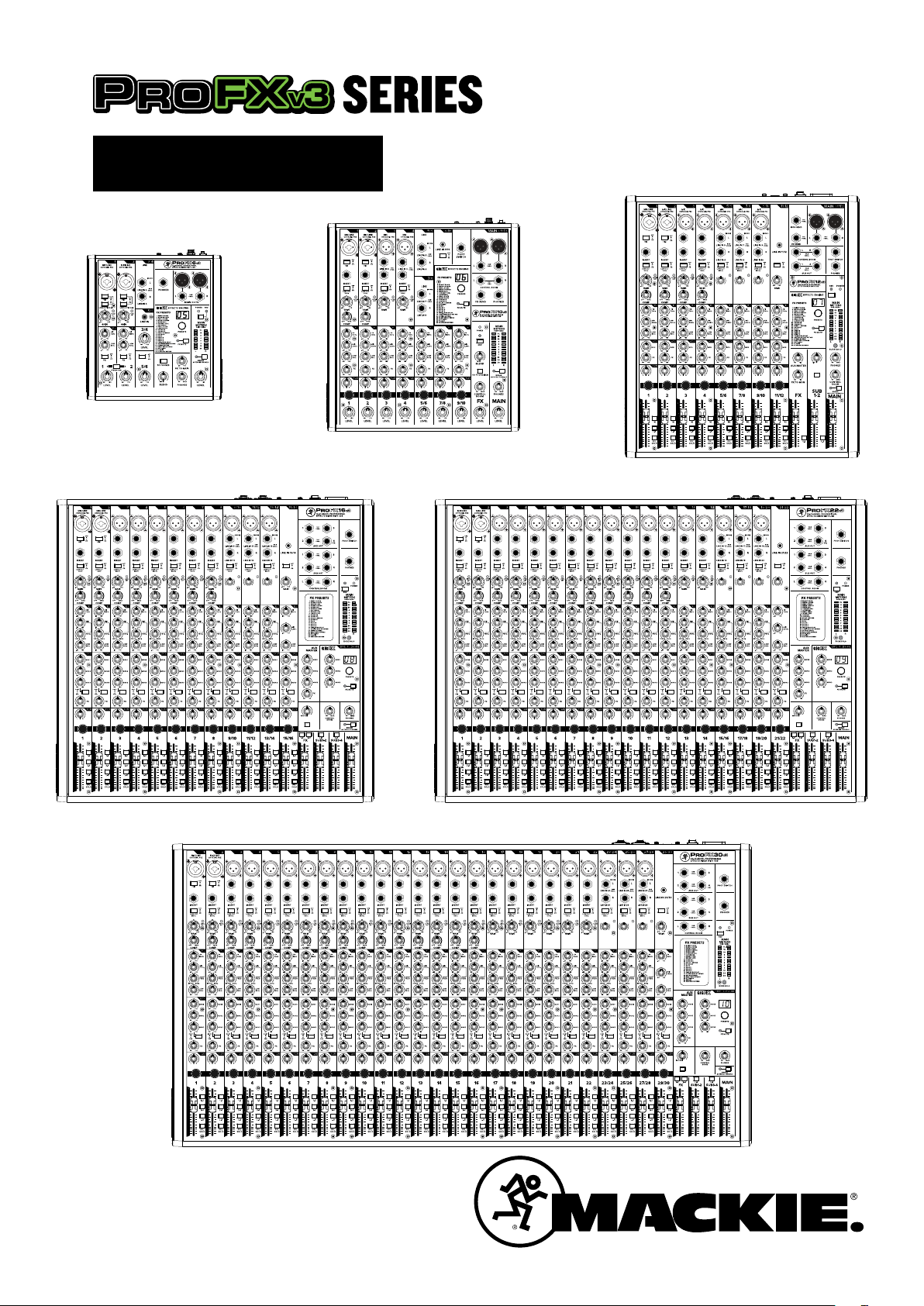
• We’ve taken our most popular mixer series
and given it major upgrades that will take
your sound quality to the next level
• Perfect for live sound, home recording, content
creation, and live streaming
• With models available in 6, 0, 2, 6, 22,
and 30 channels, you can get the perfect mixer
for your application or go big and be ready when
the need comes
Renowned Onyx Mic Preamps
• With up to 60 dB of gain and ultra-low noise,
ProFXv3 mixers allow you to sound better than ever
• Perfect for microphones popular with content
creators that require high-gain preamps
High-Resolution GigFX™ Eects Engine
• With 24 dierent FX options, from reverbs
to delays, adding some drama to your sound is
easy easy… easy….. easy…….. easy (Delay, get it?)
24-Bit / 92kHz 2x4 USB Recording Interface
• Lay down your tracks in incredible 24-Bit / 92kHz
quality for the cleanest recordings possible
• 2x4 USB I/O allows you to create two custom mixes
on your computer to send back into your ProFXv3
mixer, great for situations when you need
to monitor specific tracks during playback
in addition to the full mix
Eortless Latency-Free Monitoring
• With a single knob, you can blend between
monitoring your computer’s output and a direct
feed from the mixer
• Great for recording overdubs alongside
a pre-recorded track
Single-Knob Compression *
• Keep your input levels in check and get maximum
channel headroom with the quick turn of a knob
• Great for giving vocals the finishing touch in live,
recording, and even streaming applications
Record and Produce Like a Pro
• ProTools® | First and Waveform™ OEM professional
sofware and plugin packages included
• The Musician Collection for ProTools | First
includes 23 plugins like BBD Delay, Eleven Lite,
304 EQ, and 304C Compressor
• The DAW Essentials™ Bundle for Waveform™ OEM
includes 6 powerful plugins like Equaliser,
Compressor, Reverber8, and Limiter
Signature Rugged Design
• Legendary Built-Like-A-Tank™ design
• Solid steel chassis protects your investment
• Tough ABS side protection
Accessories
• Protective dust cover (sold separately) *
• Protective bag (sold separately) **
Limited Warranty ..........................................................................4
Like us
Follow us
Part No. SW278 Rev. A 09/9
©2019 LOUD Audio, LLC. All Rights Reserved.
* Not available for ProFX6v3
** Not available for ProFX30v3
Watch our dang videos
Owner’s Manual
3
Page 4

Getting StartedIntroduction
Mackie ProFXv3 Series Eects Mixers with USB
are the ultimate aordable solution for live sound,
home recording, and content creators available
in 6, 0, 2, 6, 22, and 30 channels.
Now with our renowned Onyx™ mic preamps that oer 60 dB
of headroom, everything from gain hungry mics to guitars
will sound better than ever. And you can keep it all in check
with easy single-knob compression.
The new GigFX™ eects engine oers 24 built-in FX
for even more options for adding the finishing touch.
Record your tracks in 24-Bit/92kHz quality with 2x4 USB
I/O with zero-latency hardware monitoring for easy overdubs.
Both ProTools® | First and Waveform™ OEM recording
sofware/plugin packages are included.
How to Use This Manual:
Afer this introduction, a getting started guide will help
ProFXv3 Professional Effects Mixer with USB
you get things set up fast. The hookup diagrams show
some typical setups, while the remaining sections provide
details of the ProFXv3 Series mixers.
The following steps will help you set up the ProFXv3 mixer
quickly.
. Turn down all knobs except the channel EQ and pan knobs,
and set all the faders fully down.
2. Set all channel EQ knobs and pan knobs at their center detent.
3. Set all buttons to the “out” position.
4. Connect cords from the main outs to powered speakers
(or to an amplifier connected to passive speakers).
5. Plug in the mixer’s power cord to a live AC outlet and turn
on the mixer.
6. If you have powered speakers, turn them on. Otherwise, hook
up your passive speakers to your amp with speaker cables,
and turn it on. Adjust your powered speaker or amplifier level
controls to however the manufacturer recommends.
7. Plug signal sources into the mixer, such as:
• Microphones plugged into the mic inputs.
Engage phantom power if your mics need it.
• Line-level sources such as keyboards, drum machines,
or CD players plugged into the line-level inputs.
This icon marks information that is critically
important or unique to ProFXv3. For your own
good, read and remember them.
This icon leads you to in-depth explanations
of features and practical tips. They usually
have some valuable nuggets of information.
This icon draws attention to certain features
and functions relating to the usage of ProFXv3.
Things to Remember:
• Never listen to loud music for prolonged periods.
Please see the Safety Instructions on page 2
for information on hearing protection.
• Save the shipping box and packing materials! You may
need them someday. Besides, the cats will love playing
in them and jumping out at you unexpectedly. Remember
to pretend like you are surprised!
• Save your sales receipt in a safe place.
8. Be sure that the volume of the input is the same as it would
be during normal use.
9. Turn the channel's gain knob clockwise until the level set LED
begins to illuminate.
0. Engage the channel’s L-R assign switch (ProFX2v3 /
ProFX6v3 / ProFX22v3 / ProFX30v3) and turn up
that channel’s fader to the “U” (unity gain) position.
. Slowly bring up the main fader to a comfortable listening
level.
2. Repeat steps 7 to 0 for the other channels.
Please write the serial numbers here for future reference
(i.e., insurance claims, tech support, return authorization,
make dad proud, etc.)
Purchased at:
Date of purchase:
4
ProFXv3 Professional Effects Mixer with USB
Page 5
Hookup Diagrams
USB 3-4
ONYX MIC PRE ONYX MIC PRE ONYX MIC PRE ONYX MIC PRE ONYX MIC PRE ONYX MIC PRE ONYX MIC PRE ONYX MIC PRE
MIC MIC MIC MIC MIC MIC
ONYX MIC PRE
MICMICMIC
LINE IN 8LINE IN 7LINE IN 6LINE IN 5LINE IN 4LINE IN 3
BAL/
UNBAL
BAL/
UNBAL
BAL/
UNBAL
BAL/
UNBAL
BAL/
UNBAL
BAL/
UNBAL
LEVEL
SET
GAIN
LEVEL
SET
GAIN
LEVEL
SET
GAIN
U +60
M
I
C
G
A
I
N
U +60
M
I
C
G
A
I
N
U +60
M
I
C
G
A
I
N
USB 1-2
TO PHONES/
CONTROL ROOM
BLEND
MUTE MUTE MUTE MUTE MUTE MUTE MUTE MUTE MUTE MUTE MUTE MUTE
Owner’s Manual
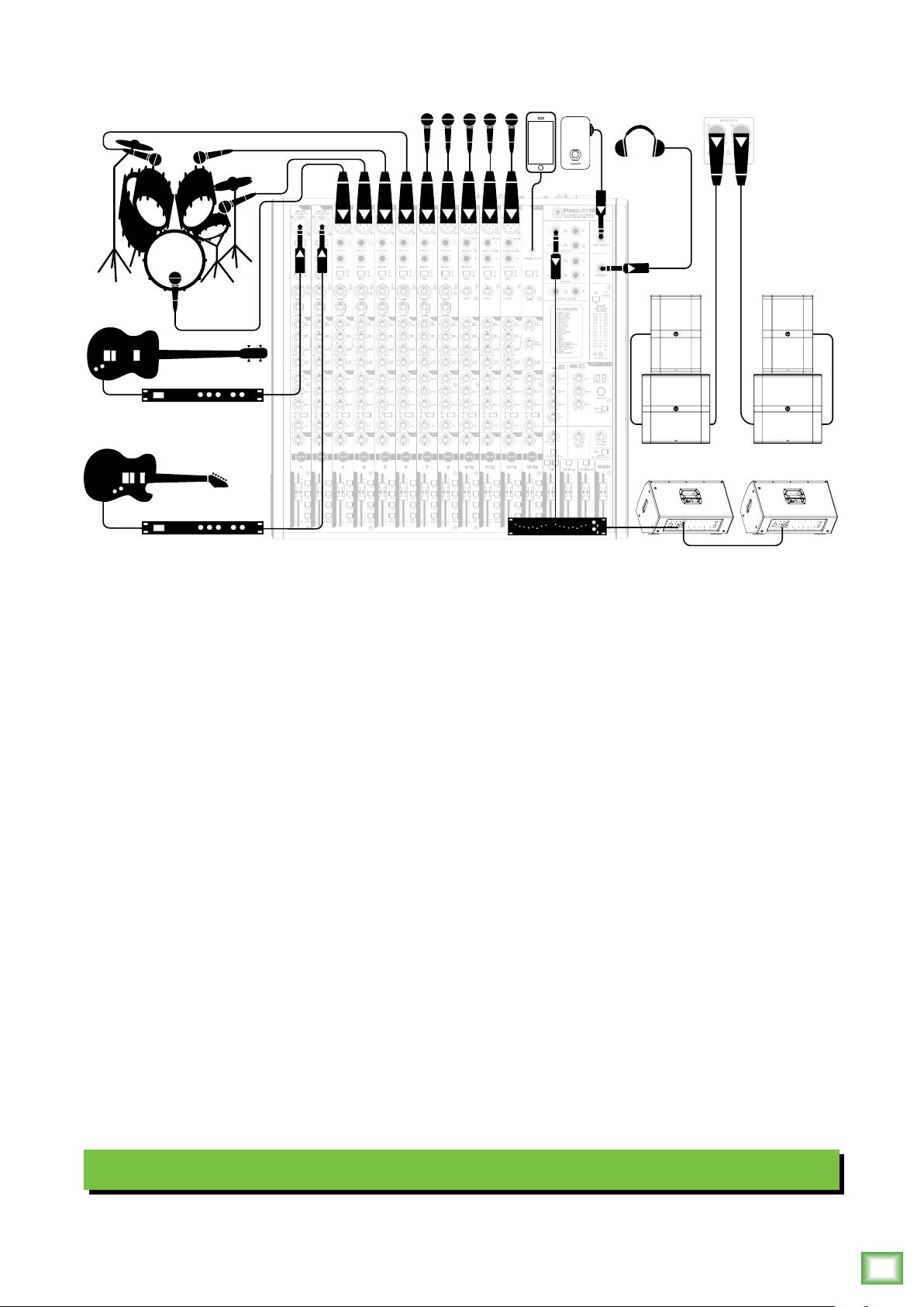
This diagram shows a bass and guitar attached to the channel and 2 line-level inputs, each
via a mono eects processor. The Hi-Z switch is engaged on both channels. A mic'd up drum
kit utilizes the next four channels of the mixer. Microphones are connected to the following five
channels and will handle lead and background vocal duties. A phone is connected to the last
channel on the board, the /8" stereo input.
DRM8S powered subwoofers are connected to the lef and right main outputs. Those are then
connected to a pair of DRM25 loudspeakers to complete the PA. Two DRM22 loudspeakers
are also set up as stage monitors and connect to the mixer's aux (monitor) output via a graphic
EQ. The aux mon controls of each channel allow you to create a stage monitor mix as desired.
Headphones are used for monitoring and a footswitch allows you to mute/unmute the internal
eects as desired.
It's not shown, but a laptop may connect to the USB port on the rear panel of the mixer.
It allows the main mix of the performance to be recorded to a DAW, as well as playback
from the computer to the main mix.
Typical Live Sound System
Owner’s Manual
5
Page 6
Hookup Diagrams Continued...
USB 3-4
ONYX MIC PRE ONYX MIC PRE ONYX MIC PRE ONYX MIC PRE ONYX MIC PRE ONYX MIC PRE ONYX MIC PRE ONYX MIC PRE
MIC MIC MIC MIC MIC MIC
ONYX MIC PRE
MICMICMIC
LINE IN 8LINE IN 7LINE IN 6LINE IN 5LINE IN 4LINE IN 3
BAL/
UNBAL
BAL/
UNBAL
BAL/
UNBAL
BAL/
UNBAL
BAL/
UNBAL
BAL/
UNBAL
LEVEL
SET
GAIN
LEVEL
SET
GAIN
LEVEL
SET
GAIN
U +60
M
I
C
G
A
I
N
U +60
M
I
C
G
A
I
N
U +60
M
I
C
G
A
I
N
USB 1-2
TO PHONES/
CONTROL ROOM
BLEND
MUTE MUTE MUTE MUTE MUTE MUTE MUTE MUTE MUTE MUTE MUTE MUTE
ProFXv3 Professional Effects Mixer with USB
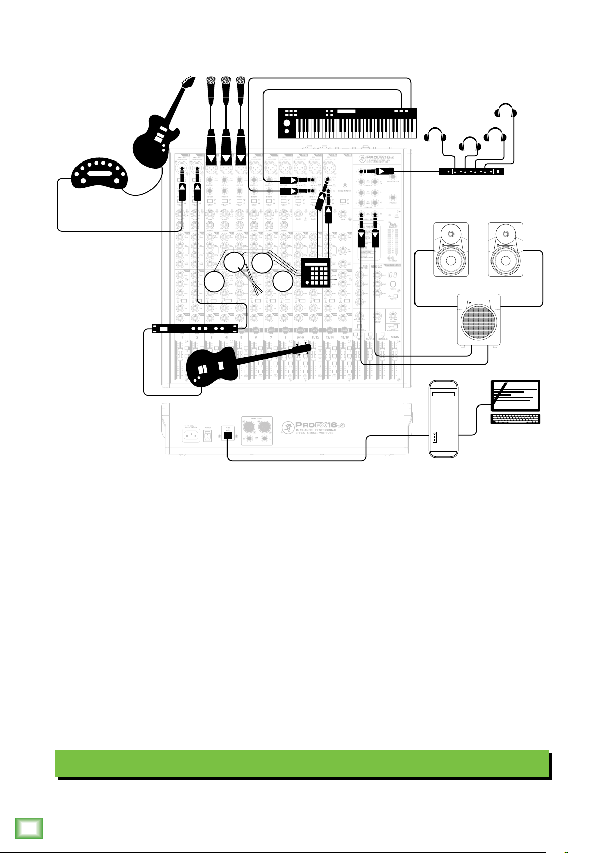
Like the previous hookup diagram, this one also starts with a bass and guitar attached
to the channel and 2 line-level inputs, each via a mono eects processor. The Hi-Z switch
is engaged on both channels. Microphones are attached to channels 3, 4 and 5, a keyboard
to stereo channels /2 and an electronic drum kit to stereo channels 3/4.
MR Series powered reference subwoofers and monitors are connected to the lef and right
control room outputs for careful and accurate monitoring of the performance. Headphones
connected to aux out via a headphone amp are available for the talent to utilize when tracking.
A desktop computer connects to the USB port to record the main mix to the DAW, as well
as play back from the DAW.
6
ProFXv3 Professional Effects Mixer with USB
Typical Recording System
Page 7
ProFXv3 Rear Panel Features
POWER
≥2.0 A
ON
ProFX6v3 • ProFX10v3
ProFX12v3
1 2 3
12 VDC IN
12 3
POWER
ON
USB
USB
MAIN OUTS
POWER USB
ON
4
BAL/
UNBAL
R
1 2 3
ProFX16v3 • ProFX22v3 • ProFX30v3
Owner’s Manual
L
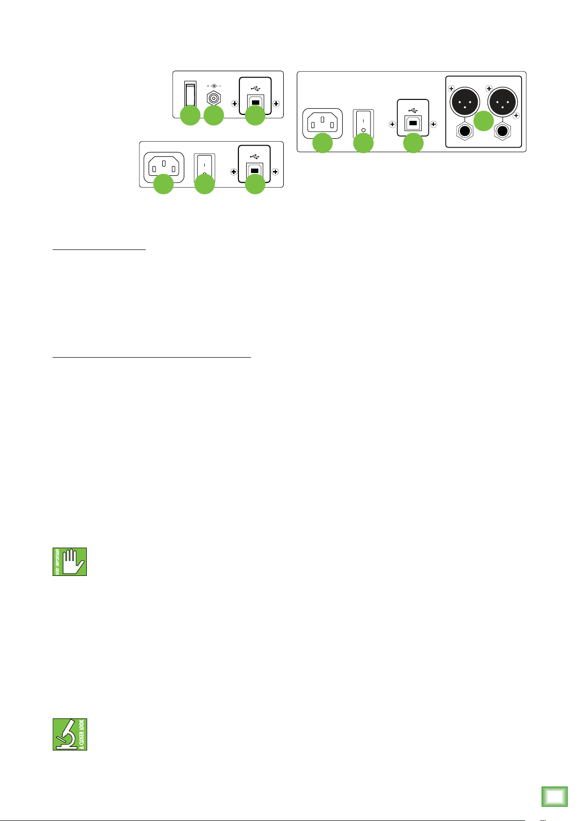
. Power Connection
ProFX6v3, ProFX0v3:
A locking barrel connector resides at one
end of the line cord. Attach it to the power
connector on the mixer and rotate the ring
clockwise to lock. Do not over-tighten!
Screw until there is resistance, then stop.
Connect the other end into a live grounded
AC outlet.
ProFX2v3, ProFX6v3, ProFX22v3, ProFX30v3:
This is a standard 3-prong IEC power
connector. Connect the detachable line
cord (included in the box with your mixer)
to the power receptacle, and plug the other
end of the line cord into an AC outlet.
ProFXv3 Series mixers have a universal power
supply that accepts any AC voltage ranging from
00 VAC to 240 VAC. No need for voltage select
switches. It will work virtually anywhere in the world.
That’s why we call it a “Planet-Earth” power supply!
It is less susceptible to voltage sags or spikes,
compared to conventional power supplies,
and provides greater electromagnetic isolation
and better protection against AC line noise.
3. USB Input / Output
The built-in USB interface allows for some powerful
and flexible routing. It is a 2x4, 24-bit / 192 kHz
high-resolution interface allowing you to record
a stereo signal to the computer via USB, and/or return
two independent audio streams of stereo playback
from a computer.
The USB routing capabilities are as follows:
USB input TO the mixer – playback:
() A USB 3-4 switch is located on the last stereo
channel – the one with the /8" input – of each mixer,
so one may route computer output (such as Spotify®,
Apple Music®, Pandora®, YouTube®, etc.) down the last
stereo channel of the board. This stereo signal may
then be EQ’d, sent to auxiliaries (i.e. to feed monitors,
headphones or eects) and is routable to mains
and/or subgroups via the fader routing features that
are available on all other channels. In short, this signal
may be sent to nearly any desired output or pair of
outputs. Additionally, the associated gain knob adjusts
the USB input level to the mixer to achieve an optimal
signal level.
Disconnecting the plug’s ground pin is
dangerous. Don’t do it.
2. Power Switch
Press the top of this rocker switch inwards to turn
on the mixer. The front panel power LED will glow
with happiness...or at least it will if you have the mixer
plugged into a suitable live AC mains supply.
Press the bottom of this switch to turn the mixer
o. It will not work at this point, but makes a handy
paperweight.
As a general guide, you should turn
on the mixer first, before any external
power amplifiers or powered speakers,
and turn it o last. This will reduce the possibility
of any turn-on, or turn-o thumps in your speakers.
(2) A USB -2 blend knob and To Phones / Control
Room switch is located near the lower-right side
of each mixer so one may route the computer’s DAW
output (such as Pro Tools®, Tracktion®, Cubase®,
Reaper®, etc.) to the mixer and blend that signal
with the live inputs of the mixer in the headphones
for latency-free monitoring.
USB output FROM the mixer – recording, etc:
It is possible to record the main mix to take home
a copy of the live show. These levels are pre-main fader.
Therefore, levels may be mixed up or down in the DAW
later depending on the needs of the recording versus
the live show. The end result is that fade-ins and/or
fade-outs made during the show do not aect recorded
levels.
Owner’s Manual
7
Page 8
4. Main Outputs
The main outputs provide a line-level signal
that represents the end of the mixer chain, where
the fully mixed stereo signal enters the real world.
Connect these to the lef and right inputs of your
main power amplifiers, powered speakers, or
serial eects processor (like a graphic equalizer
or compressor/limiter).
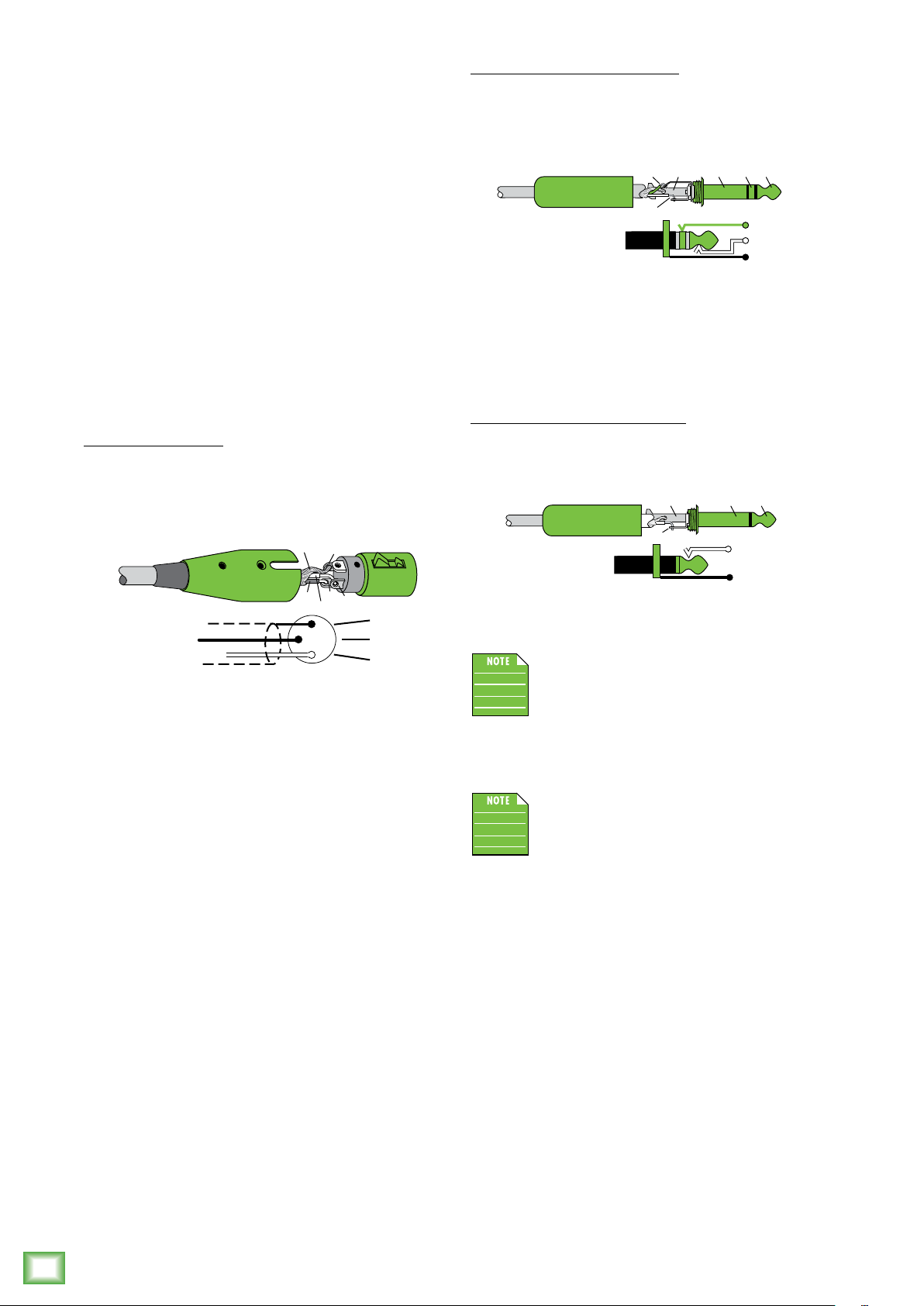
The male XLR connectors provide a balanced
line-level signal and is wired as follows, according
to standards specified by the AES (Audio Engineering
Society):
XLR Balanced Wiring:
Pin = Shield (ground)
Pin 2 = Positive (+ or hot)
Pin 3 = Negative (– or cold)
SHIELD
1
ProFXv3 Professional Effects Mixer with USB
3
COLD
2
HOT
1
3
2
SHIELD
COLD
HOT
/4" TRS Balanced Mono Wiring:
Sleeve = Shield
Tip = Hot (+)
Ring = Cold (–)
TIPSLEEVE
SLEEVERING
TIP
RING
RING
TIP
SLEEVE
To connect unbalanced lines to these outputs,
use a /4" mono (TS) phone plug, wired as follows:
/4" TS Unbalanced Mono Wiring:
Sleeve = Shield
Tip = Hot (+)
SLEEVE
TIP
TIPSLEEVE
TIP
SLEEVE
The main outputs are located on the front
panel of the ProFX6v3, ProFX0v3 and
ProFX2v3 and on the rear panel of the
ProFX6v3, ProFX22v3 and ProFX30v3.
In addition to accepting balanced XLR connectors,
the main outputs may also accept /4" connectors
driven by balanced or unbalanced sources.
To connect balanced lines to these outputs, use
a /4" Tip-Ring-Sleeve (TRS) plug. “TRS” stands
for Tip-Ring-Sleeve, the three connection points
available on a stereo /4" or balanced phone jack
or plug. TRS jacks and plugs are used for balanced
signals and are wired as follows:
The XLR outputs are 6 dB hotter than
the TRS outputs. When the meters read “0”,
the TRS outputs are at 0 dBu.
8
ProFXv3 Professional Effects Mixer with USB
Page 9
ProFXv3 Front Panel Features
2
Connections and Channel Strip
MIC
ONYX MIC PRE
5 7
MIC
ONYX MIC PRE
MIC
ONYX MIC PRE
Owner’s Manual
Phantom Power
Most modern professional condenser mics require
48V phantom power, which lets the mixer send
low-current DC voltage to the mic’s electronics
through the same wires that carry audio. (Semi-pro
condenser mics ofen have batteries to accomplish
the same thing.) “Phantom” owes its name to an ability
to be “unseen” by dynamic mics (Shure SM57/SM58,
for instance), which don’t need external power and
aren’t aected by it anyway.
The ProFXv3 mixer’s phantom power is
globally controlled by the phantom power
switch (meaning that phantom power for
all mic inputs is turned on and o together.)
Never plug single-ended (unbalanced)
micro phones or ribbon microphones into
the mic input jacks if phantom power is on.
Do not plug instrument outputs into the mic input jacks
with phantom power on unless you know for certain it
is safe to do so.
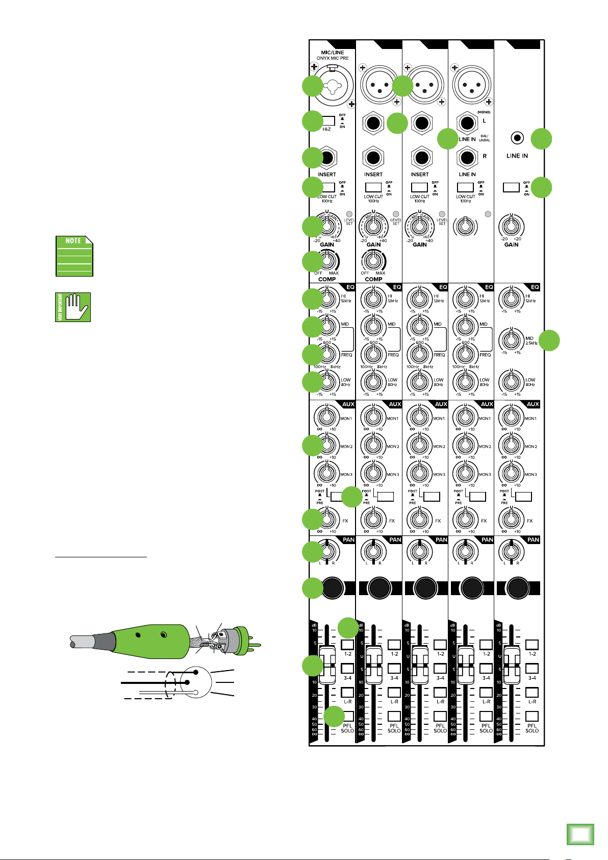
The vertical channel strips look very similar between
each model and have only a few dierences between
them. Each channel works independently, and just
controls the signals plugged into the inputs directly
above them.
6
11
12
13
14
15
16
17
19
LINE IN
BAL/
UNBAL
8
LINE IN
BAL/
UNBAL
9 10
USB 3-4
G
A
C
I
I
N
M
LEVEL
SET
U +60
GAIN
28
18
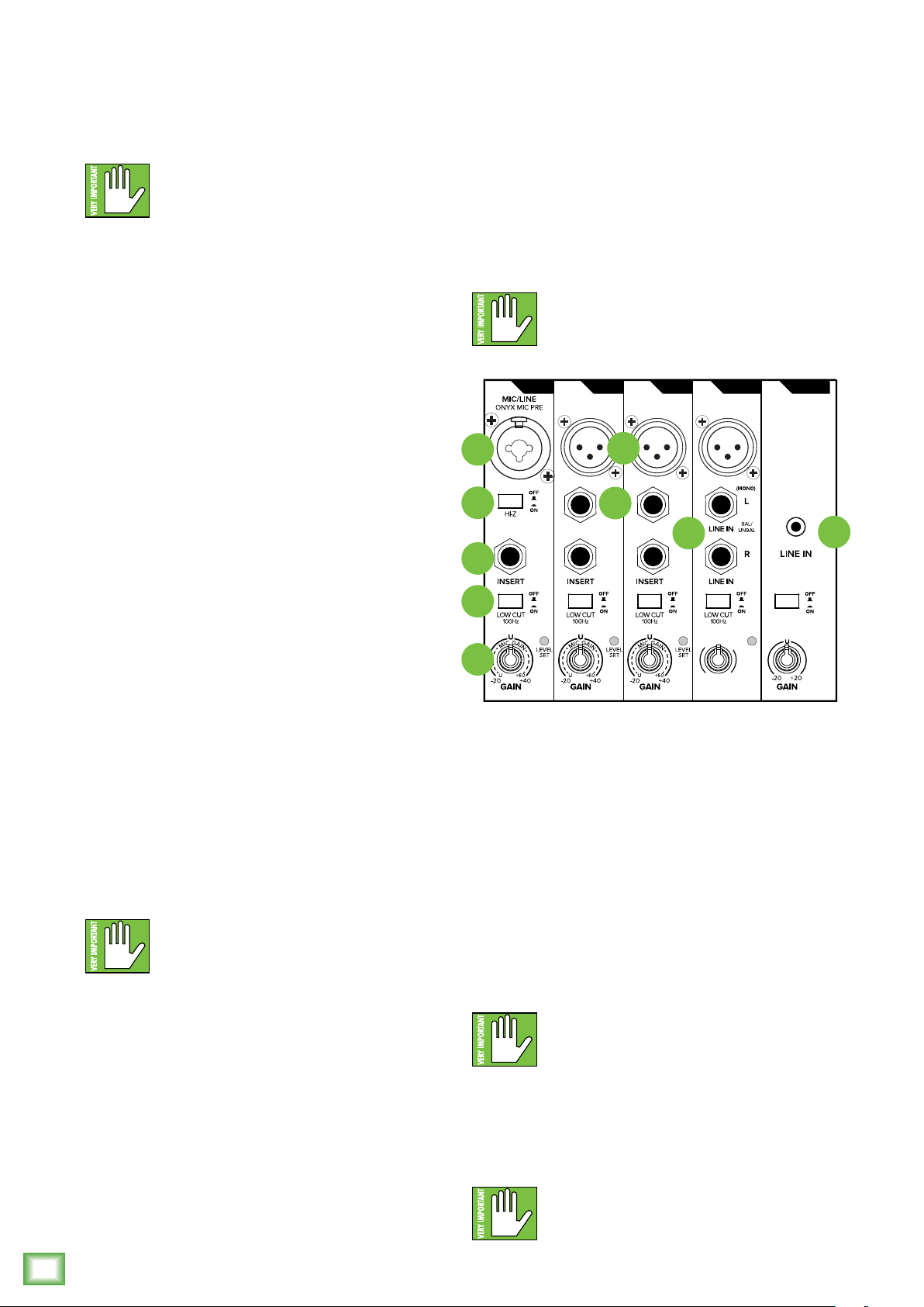
5. XLR and /4" Combo Inputs [Chs. and 2]
Input channels and 2 on all ProFXv3 models
may accept a balanced mic or line-level signal using
an XLR connector. They are wired as follows, according
to standards specified by the AES (Audio Engineering
Society).
XLR Balanced Wiring:
Pin = Shield (ground)
Pin 2 = Positive (+ or hot)
Pin 3 = Negative (– or cold)
SHIELD
HOT
1
3
COLD
1
3
2
Both channels may also accept /4" line-level
signals driven by balanced or unbalanced sources.
Additionally, both channels may accept Hi-Z sources
(such as guitars) via the /4" input without the need
for a separate DI box. Don't forget to engage the Hi-Z
switch, though!
SHIELD
COLD
HOT
20
21
22
23
MUTE MUTE MUTE MUTE MUTE
24
25
27
26
Owner’s Manual
9
Page 10
To connect balanced lines to these inputs,
use a /4" Tip-Ring-Sleeve (TRS) plug. To connect
unbalanced lines to these inputs, use a /4" mono (TS)
phone plug. Wiring diagrams for both connectors
are presented on page 8.
NEVER connect the output of an amplifier
directly to a ProFXv3’s input jack. This could
damage the input circuitry and we wouldn’t
want that now, would we?
8. Line Ins
These /4" jacks share circuitry (but not phantom
power) with the mic preamps, and can be driven by
balanced or unbalanced sources at almost any level.
You can use these inputs for virtually any signal you’ll
come across.
To connect balanced lines to these inputs, use a /4"
Tip-Ring-Sleeve (TRS) plug. To connect unbalanced
lines to these inputs, use a /4" mono (TS) phone plug.
Wiring diagrams for both connectors are presented on
page 8.
6. Line / Hi-Z Switch [Chs. and 2]
To connect a guitar directly to the mixer without
using a DI Box, press this switch in first; then connect
the output from the guitar to the channel’s /4" TRS
input. The input impedance is optimized for direct
connection and high-frequency fidelity is assured.
In the out position, the channel’s /4" TRS input
becomes a line input just like the other mono line
inputs.
To use guitars or other instruments on other
channels, you will need to use an external DI box first.
Without the DI box – or if this switch is not pressed
in – guitars may sound dull and muddy.
ProFXv3 Professional Effects Mixer with USB
7. Mic Ins
This is a female XLR connector that accepts a
balanced mic or line level input from almost any type
of source. These Onyx mic preamps feature higher
fidelity and headroom rivaling any standalone mic
preamp on the market today. These circuits are
excellent at rejecting hum and noise.
Professional ribbon, dynamic, and condenser
mics all sound excellent through these inputs.
The mic / line inputs will handle any kind of level
you can toss at them, without overloading.
Wiring diagrams for these XLR connectors
are presented on the previous page.
NEVER connect the output of an amplifier
directly to a ProFXv3’s input jack. This could
damage the input circuitry and we wouldn’t
want that now, would we?
NEVER connect the output of an amplifier
directly to a ProFXv3’s input jack. This could
damage the input circuitry and we wouldn’t
want that now, would we?
5
6
MIC
ONYX MIC PRE
LINE IN
BAL/
UNBAL
7
8
MIC
ONYX MIC PRE
LINE IN
BAL/
UNBAL
9
MIC
ONYX MIC PRE
11
12
G
A
C
I
I
M
13
9. Stereo Line Inputs
The stereo line inputs are designed for /4" TRS
balanced or /4" TS unbalanced signals. They may
accept any line-level instrument, eects device, CD
player, etc.
If you are connecting a mono source, use the lef
(mono) input, and the mono signals will appear
on both sides of the main mix.
To connect balanced lines to these inputs, use a /4"
Tip-Ring-Sleeve (TRS) plug. To connect unbalanced
lines to these inputs, use a /4" mono (TS) phone plug.
Wiring diagrams for both connectors are presented on
page 8.
U +60
GAIN
USB 3-4
N
LEVEL
SET
10
10
NEVER connect the output of an amplifier
directly to a ProFXv3’s input jack. This could
damage the input circuitry and we wouldn’t
want that now, would we?
0. /8" Stereo Input
This stereo input may accept an /8" line-level signal
from a phone, MP3 player, or other signal source.
Last one! NEVER connect the output of an
amplifier directly to a ProFXv3’s input jack.
This could damage the input circuitry and
we wouldn’t want that now, would we?
ProFXv3 Professional Effects Mixer with USB
Page 11
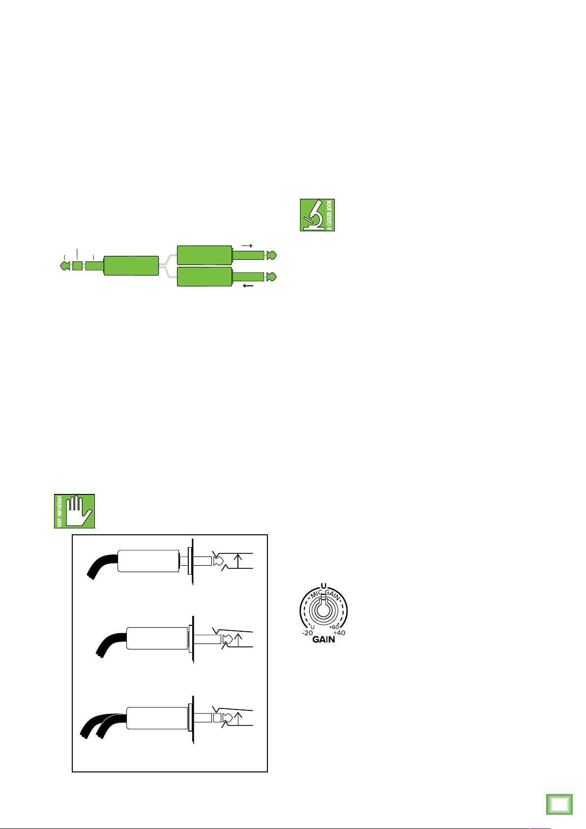
. Insert Jacks
tip
This plug connects to one of
the mixer’s channel insert jacks.
ring
tip
ring
sleeve
SEND to processor
RETURN from processor
(TRS plug)
Direct out with no signal interruption to master.
Insert only to first “click.”
Channel Insert jack
Channel Insert jack
Channel Insert jack
Direct out with signal interruption to master.
Insert all the way in to the second “click.”
For use as an eects loop.
(TIP = SEND to eect, RING = RETURN from eect.)
MONO PLUG
MONO PLUG
STEREO
PLUG
These unbalanced /4" jacks are for connecting
serial eects processors such as compressors,
equalizers, de-essers, or filters.
Owner’s Manual
2. Low Cut Switches
All channels with a mic input have a low-cut switch
(ofen referred to as a high-pass filter) that cuts bass
frequencies below 00 Hz at a rate of 8 dB per octave.
The insert point is afer the gain control and low
cut filter, but before the channel’s EQ and level.
The channel signal can go out of the insert jack
to an external device, be processed and come back
in on the same insert jack.
To do this requires a standard insert cable that must
be wired thusly:
Tip = send (output to eects device)
Ring = return (input from eects device)
Sleeve = common ground
Insert jacks may be used as channel direct outputs;
post-gain, and pre-EQ. If you insert a TS (mono) /4"
plug only partially (to the first click) into an insert jack,
the plug will not activate the jack switch and will not
open the insert loop in the circuit (thereby allowing
the channel signal to continue on its merry way through
the mixer).
This allows you to tap out the channel signal without
interrupting normal operation.
If you push the /4" TS plug in to the second click,
you will open the jack switch and create a direct out,
which does interrupt the signal in that channel.
See illustration below.
Do not overload or short-circuit the signal
you are tapping from the mixer. That will
aect the internal signal.
We recommend that you use low-cut on every
microphone application except kick drum, bass guitar,
or bassy synth patches. These aside, there isn’t much
down there that you want to hear, and filtering it
out makes the low stu you do want much more crisp
and tasty. Not only that, but low-cut can help reduce
the possibility of feedback in live situations, and it
helps to conserve amplifier power.
Another way to consider low-cut’s function
is that it actually adds flexibility during live
performances. With the addition of low-cut,
you can safely use low equalization on vocals.
Many times, bass shelving EQ can really benefit voices.
Trouble is, adding low EQ also boosts stage rumble,
mic handling clunks and breath pops from way-down
low. Applying low-cut removes all those problems,
so you can add low EQ without blowing the woofers.
“U” like Unity gain
ProFXv3 Series mixers have a “U” symbol on almost
every level control. It stands for “unity gain,” meaning
no change in signal level. The labels on the controls
are measured in decibels (dB), so you’ll know what
you’re doing level-wise if you choose to change a
control’s settings.
3. Gain Knobs and Level Set LEDs
If you haven’t already, please read the "Getting
Started" section on page 4. Setting the gain correctly
will ensure that the preamplifier’s gain is not too high,
where distortion could occur, and not too low, where
the quieter, exquisitely-delicate passages might be lost
in background noise.
The gain knobs – in conjunction with the level set
LEDs – adjust the input sensitivity of the mic and line
inputs. This allows signals from the outside world
to be adjusted to run through each channel at optimal
internal operating levels.
For mono channels (mic input with
a mono line input), the gain knob
adjusts the input sensitivity of the
mic and line inputs.
If the signal originates through the mic XLR jack,
there will be 0 dB of gain with the knob fully down,
ramping to 60 dB of gain fully up.
Through the /4" mono line inputs, there is –20 dB
of attenuation fully down and 40 dB of gain fully up,
with unity gain “U” at 2:00.
This 20 dB of attenuation can be very handy when
you are inserting a hot signal, or when you want to add
EQ gain, or both. Without this “virtual pad,” there is
more chance of channel clipping.
Owner’s Manual
11
Page 12
GAIN
I
C
G
A
I
N
M
For hybrid channels (mic input and stereo
line input), the gain control just aects
U +60
the microphone input.
Hybrid Channels:
• ProFX6v3 – Channels 3/4 (no gain knob)
• ProFX0v3 – Channels 5/6 – 7/8 (no gain knobs)
• ProFX2v3 – Channels 5/6 – 9/0
• ProFX6v3 – Channels 9/0 – 3/4
• ProFX22v3 – Channels 5/6 – 9/20
• ProFX30v3 – Channels 23/24 – 27/28
The gain control on the /8" stereo input
channel has 20 dB of gain and 20 dB
of attenuation.
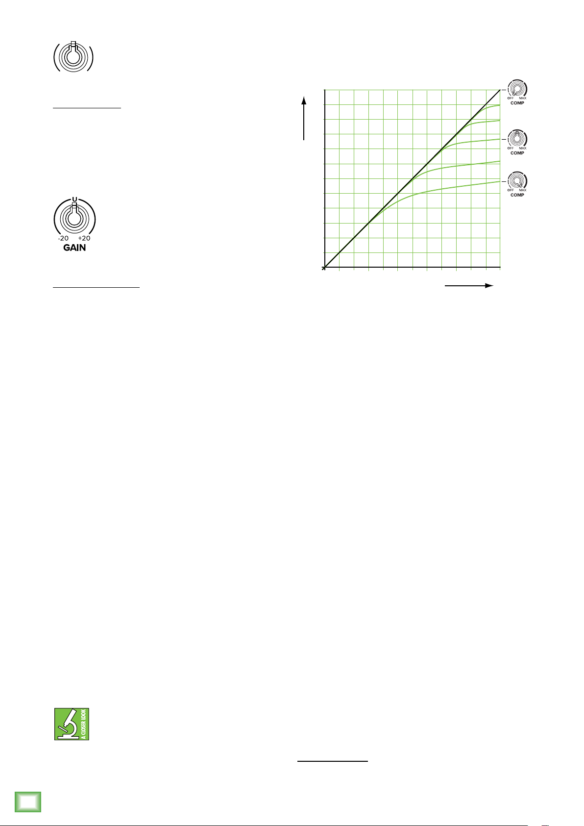
The compression ratio is fixed at around 6:, with a
sof knee response. The threshold can be adjusted
clockwise from o (no compression) to 0 dBu (max).
+20
+15
+10
+5
SLOPE 6:1
+0
OUTPUT SIGNAL STRENGTH dBu
-5
SLOPE 1:1
SOFT KNEE
1/8" Stereo Channels:
• ProFX6v3 – Channels 5/6 (no gain knob)
• ProFX0v3 – Channels 9/0 (no gain knobs)
• ProFX2v3 – Channels /2
• ProFX6v3 – Channels 5/6
• ProFX22v3 – Channels 2/22
• ProFX30v3 – Channels 29/30
ProFXv3 Professional Effects Mixer with USB
Next to every gain knob – except the /8" stereo input
gain knob – lies a level set LED. These LEDs are used
with the gain control to set the channel preamplifier
gain just right for each source. If one or more channels
are distorting, check the level set LEDs. If they are on
continuously, turn down the gain.
4. Compressor Knobs
The following channels of each ProFXv3 mixer has
an in-line compressor circuit with a variable threshold.
• ProFX6v3 – No compressor knobs
• ProFX0v3 – Channels – 2
• ProFX2v3 – Channels – 4
• ProFX6v3 – Channels – 8
• ProFX22v3 – Channels – 2
• ProFX30v3 – Channels – 6
This is very useful for compression of vocals,
and snare drums, for example, so you might consider
connecting your vocal and drum mics to these
channels, rather than one of the other channels.
When the incoming signal exceeds the threshold
level set by this knob, the signal level is automatically
compressed. This reduces the dynamic range and
reduces the chance of distortion due to overloading
the input signals.
constant volume level for the signal. It helps sources,
such as vocals, “sit” properly in the mix; it is very useful
for live sound.
Dynamic range is the dierence in level
between the quietest and loudest parts of a
song. A compressor “squeezes” the dynamic
range, resulting in an overall steadier, more
-10
+5 +10 +15
INPUT SIGNAL STRENGTH dBu
+20-10 -5 +0
As an example, suppose the threshold is set to
maximum. An incoming signal reaches the threshold of
0 dBu. As it increases beyond the threshold, it becomes
compressed at a ratio of 6:. This means that even if
the input further increases by 6 dB, the actual output
only increases by dB. This compresses the output
signal, so there is more protection to your system
from distortion and overload due to poor microphone
technique (say it ain't so) and general pops, bangs and
heavy metal screaming. The sof knee means that the
compression slowly ramps up to 6: from the threshold.
It does not jump abruptly to 6:, as this would be hard
knee compression, and harder on the ears too.
The graph above shows the input signal level
going into the compressor, versus the output level
coming out of it. It is the typical graph to view when
compressors are discussed, and is just the kind
of thing our engineers like to discuss during the
company Christmas party.
If the compressor is o, then the input = output. For
example, an input signal level of +5 dBu results in an
output level of +5 dBu. The diagonal line from lower lef
to upper right represents x = y, that is, input = output.
At the maximum compression, the threshold
is set at 0 dBu, and the input to output relationship
is represented by the lower curve. If the input is –5 dBu
(that is, below the threshold), the output is –5 dBu.
As the input reaches 0 dBu, the output is a bit less
than 0 dBu. If the input is +5 dBu, the output is about
+2 dBu. If the input reaches +0 dBu, then the output
is +3 dBu. Notice the shapely curve of the sof knee
between the diagonal slope of x = y and the compressor
slope of 6: (the compression ratio).
My High School math teacher, Mr. Marvin, thought that graphs might come
in handy for me one day. Finally!
12
ProFXv3 Professional Effects Mixer with USB
Page 13
The other green curves represent in-between
+15
+
–
–
+15
+
–
20 Hz 100 Hz 1 kHz 10 k 20 k
–
+15
+
–
–
+
–
20 Hz 100 Hz 1 kHz 10 k 20 k
–
positions of the compressor knob, with higher
thresholds before compression begins.
Outboard compressors ofen have controls such as
compression ratio, threshold, sof knee/hard knee,
attack time, and release time. These last two aect how
quickly the compressor kicks in when the input exceeds
the threshold, and how quickly it is released afer it
drops below the threshold. In this compressor, these
parameters are specially chosen to give you the best
overall performance.
Adjust the threshold carefully, so your dynamic range
is still lovely, without distortion or overload during the
performance. Run through a few practice screams and
high-notes, and adjust the compression as required.
Channel Equalization (EQ)
All ProFXv3 mixers – except for the ProFX6v3 – have
3-band EQ with shelving hi, peaking mid with adjustable
mid frequency [ProFX6v3, ProFX22v3, ProFX30v3]
and shelving low.
The ProFX6v3 has 2-band EQ: shelving hi
and shelving low.
Shelving means that the circuitry boosts or cuts all
frequencies past the specified frequency. For example,
the low EQ boosts bass frequencies below 80 Hz and
continuing down to the lowest note you never heard.
Peaking means that certain frequencies form a “hill”
around the center frequency.
With too much EQ, you can really upset
things. We’ve designed a lot of boost
and cut into each equalizer circuit because
we know that everyone will occasionally
need that. But if you max the EQ on every channel, you’ll
get mix mush. Equalize subtly and use the lef sides
of the knobs (cut), as well as the right (boost).
If you find yourself repeatedly using a lot of boost
or cut, consider altering the sound source, such
as placing a mic dierently, trying a dierent kind
of mic, a dierent vocalist, changing the strings,
or gargling.
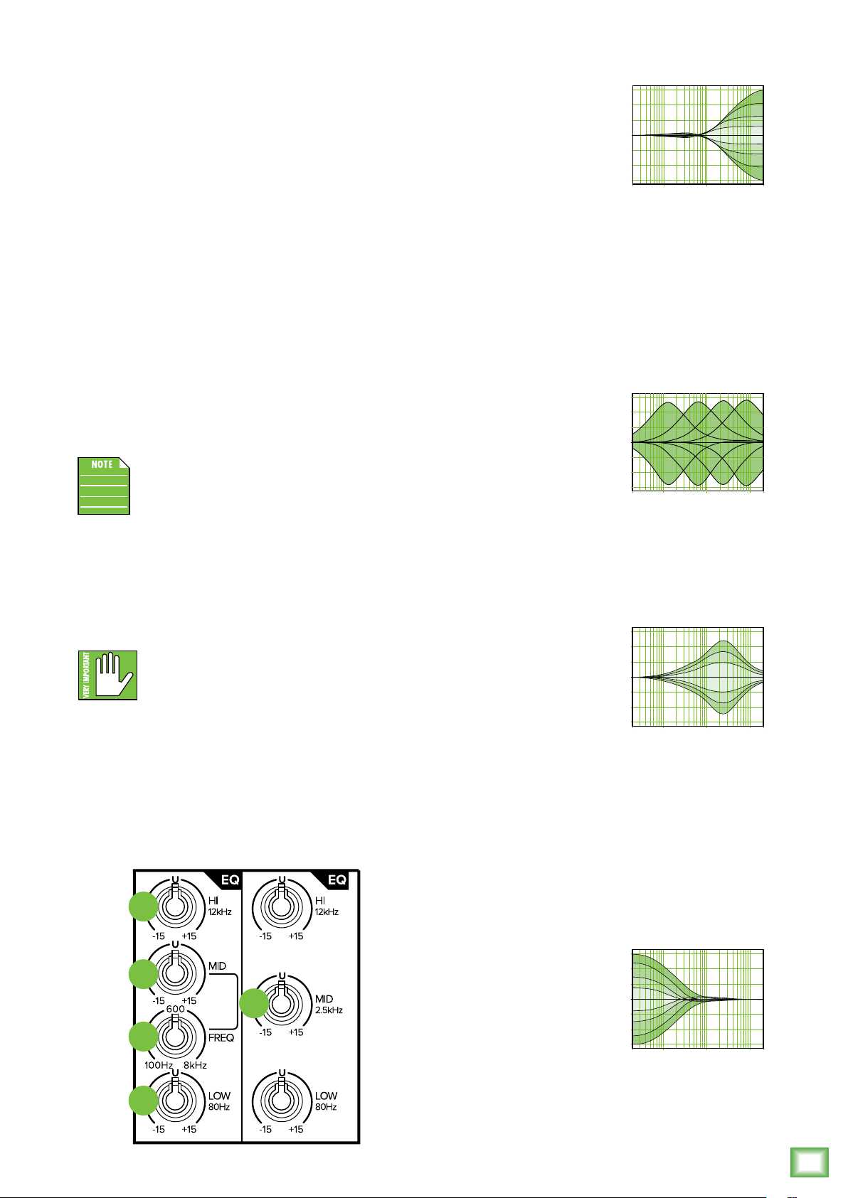
5. Hi EQ Knobs
The hi EQ provides up
to 5 dB of boost or cut above
2 kHz, and it is also flat
(no boost or cut) at the
detent. Use it to add sizzle
to cymbals, an overall sense
of transparency, or an edge
10
+5
0
–5
10
15
to keyboards, vocals, guitar
and bacon frying. Turn it down
a little to reduce sibilance
or to mask tape hiss.
6. Mid EQ Knobs
7. Freq Knobs
[ProFX6v3, ProFX22v3, ProFX30v3]
The ProFX6v3, ProFX22v3
and ProFX30v3 mixers employ
a semi-parametric mid-sweep
EQ. The gain (up to 5 dB
of boost or cut) is set via
the mid EQ, and then “aimed”
at a specific frequency, from
10
+5
0
–5
10
15
00 Hz to 8 kHz, via the freq
control.
8. Mid EQ Knobs
Short for “midrange,” this
knob provides up to 5 dB
of boost or cut, centered
at 2.5 kHz, also flat
at the center detent.
Midrange EQ is ofen thought
of as the most dynamic,
because the frequencies
that define any particular
sound are almost always
found in this range. You can
create many interesting and
useful EQ changes by turning
this knob down as well as up.
10
+5
0
–5
10
15
Owner’s Manual
15
16
17
19
18
9. Low EQ Knobs
The low EQ provides up
to 5 dB of boost or cut below
80 Hz. The circuit is flat
at the center detent position.
This frequency represents
the punch in bass drums,
bass guitar, fat synth patches,
and some really serious male
singers who eat raw beef
for breakfast.
+15
10
+5
0
–5
10
15
Owner’s Manual
13
Page 14

20. Aux Mon Knobs
These knobs tap a portion of each channel's signal
to set up a nice monitor mix feeding stage monitors,
independent of the main mix. Adjust these controls
on each channel until the band is happy with the stage
monitor mix.
The controls are o when fully turned down, deliver
unity gain at the center detent, and can provide up
to 0 dB of gain turned fully up.
The pan, mute and channel fader do not aect
the monitor output, but the other channel controls will.
The aux mon is pre-fader.
The overall output level may be adjusted with the aux
master mon controls. Internal FX may also be added
to the monitor mix with the GigFX master mon knobs.
2. Pre-Fader Switches
Aux sends -2 are always
pre-fader, designed for stage
monitor applications. Aux send 3
may be set to pre- or post-fader,
so they may be used for monitors
or eects.
ProFXv3 Professional Effects Mixer with USB
Pre-fader: with the pre switch
engaged (pressed in, not
commited to marriage), aux 3
delivers signals post-insert,
post-low cut, post EQ, post-mute
and pre-fader. Any changes made
to the channel controls, except
the fader, will aect the aux send
signal.
Post-fader: with the pre switch
disengaged (up), aux 3 delivers
signals post-insert, post-low cut,
post-mute, post-EQ and
post-fader. Any changes made
to the channel controls will aect
the aux send signal.
20
22
23
The FX signal reaching the internal FX processor
and the FX send output jack is the sum (mix) of all
the channels whose aux FX control is set to more than
minimum.
The overall output level may be adjusted with the aux
master FX knob. FX are then added to the main mix
and subs -4 by raising the level of the FX fader.
FX Switches (Chs. –2) [ProFX6v3]
With this switch out, no FX are added to the mix.
With this switch in, the channel is assigned to the FX
send post-channel level knob.
ProFX6v3
Stereo Pan Switch (Chs. –2) [ProFX6v3]
With this switch out, each mono channel feeds
both the lef and right sides of the main mix equally.
For example:
• Playing a mono source: If you talk into a microphone
connected to input , your sweet tones will be heard
in both the lef and right loudspeakers.
21
• Overdubbing a mono source: if you are
monitoring directly through the headphones,
you can hear the overdub signal in both ears
while you are playing.
With this switch pressed in, channel will play only
in the lef side of the main mix, and channel 2 will play
in the right side. For example:
• Recording a stereo source: If you have a stereo
microphone connected to the mic inputs, or if you
are playing a stereo source into the line inputs,
each side of the source can be recorded discretely
onto a recorder connected to the main outputs.
14
22. Aux FX Knobs
These knobs tap a portion of each channel’s signal to
set up a nice FX mix feeding the internal FX processor,
and to feed external processors via the FX send.
The controls are o when fully turned down, deliver
unity gain at the center detent, and can provide up
to 0 dB of gain turned fully up.
The mute, channel fader and other channel controls
aect the FX output, but pan does not. The aux FX is
post-fader.
ProFXv3 Professional Effects Mixer with USB
The pan switch does not aect the other channels.
23. Pan Knobs
This control allows you to adjust how much of
the channel signal is sent to the lef versus the right
outputs.
The pan control employs a design called “Constant
Loudness.” If you have a channel panned hard lef
(or right) and then pan to the center, the signal is
attenuated about 3 dB to maintain the same apparent
loudness. Otherwise, it would make the sound appear
much louder when panned center.
Page 15

24. Mute Switches
Mute switches do just what they sound like they do.
They turn o the signal by “routing” it into oblivion.
Engaging a channel’s mute switch (almost) provides
the same results as turning the fader all the way down
(a pre-aux send is not aected by the channel fader,
but it is by the mute switch).
Any channel assignments to the main mix, subgroup
-2 or subgroup 3-4 will be interrupted and all of the
aux sends will be silenced (both pre- and post-fader).
The channel insert will continue to provide a
signal when a channel is muted. The mute button will
illuminate when a channel's mute switch is engaged.
Mute switches are available on all ProFXv3
mixers except the ProFX6v3.
25. Assign Switches
[ProFX2v3, ProFX6v3,
ProFX22v3, ProFX30v3]
Alongside each channel fader are buttons referred
to as channel assignment switches. Used in conjunction
with the channel’s pan knob, they are used to determine
the destination of the channel’s signal.
With the pan knob at the center detent, the lef
and right sides receive equal signal levels (main
mix L/R, sub -2 and sub 3-4). To feed only one
side or the other, turn the pan knob accordingly.
If you are doing a mixdown
to a 2-track, for example,
simply engage the main mix
switch on each channel that
you want to hear, and they will
be sent to the main mix bus.
If you want to create a group
of certain channels, engage
either the -2 or 3-4 switches
instead of the main mix,
and they will be sent to
the appropriate subgroup
faders. From there, the groups
may be sent back to the main
mix (using the group assign
switches above the group
faders), allowing you to use
the group faders as a master
control for those channels.
If you are creating new
tracks or bouncing existing
ones, you will also use the -2
and 3-4 switches, but not
the main mix switch. Here you
do not want the groups sent
back into the main mix bus, but sent out,
via the sub out jacks, to your multitrack inputs.
24
27
MUTE
25
26
26. PFL Solo Switches
[ProFX2v3, ProFX6v3,
ProFX22v3, ProFX30v3]
When a channel’s solo switch is engaged, any existing
selection is replaced by the solo signal, appearing
at the control room outputs, phones and at the lef
meter. The audible solo levels are then controlled
by the CR and phones knobs. The solo levels appearing
on the meters are not controlled by the CR and phones
knob – you would not want that, anyway. What you
do want to see is the actual channel level on the meters
regardless of how loud the control room and phones
output levels might be.
PFL means Pre-Fader Listen (post-EQ). With the PFL
Solo switch engaged, solo will not be aected by a
channel's mute switch position.
Remember, PFL taps the channel signal before
the fader. If you have a channel’s fader set
way below “U” (unity gain), solo will not know
that and will send a unity gain signal to the CR outs,
phones output and meter display, which may raise some
eyebrows.
27. Channel Faders
This is the last control in a channel’s signal path, and
it adjusts the level of each channel onto the main mix.
The “U” mark indicates unity gain, meaning no increase
or decrease of signal level. All the way up provides an
additional 0 dB, should you need to boost a section of
a song. If you find that the overall level is too quiet or
too loud with the level near unity, check that the gain
control is set correctly.
The “Channel Faders” on the ProFX6v3
and ProFX10v3 are actually "Channel Knobs".
But they behave similarly.
28. USB Switch
When engaged, this switch
overrides the /8" input and allows
the USB return – stereo playback
of iTunes® or a DAW via the USB
connection, for example – to flow
through the signal path instead. Like any other input,
this signal may also be EQ’d, sent to an aux bus,
or mixed in with the other signals and assigned
to subgroups or main outs.
USB 3-4
Owner’s Manual
Owner’s Manual
15
Page 16

Additional Inputs and Outputs
29
31
30. FX Send
[ProFX0v3, ProFX2v3, ProFX6v3,
ProFX22v3, ProFX30v3]
This /4" TRS line-level output may be used to feed
an external eects processor (FX), such as a nice
sound eect or delay unit. The output from this jack
is an exact copy of what goes into the internal FX
processor, being the careful mix of all channels whose
aux FX control is turned to more than minimum.
30
32
33
PENCIL SHARPENER
29. Aux Out / Mon Send
[ProFX2v3, ProFX6v3,
ProFXv3 Professional Effects Mixer with USB
ProFX22v3, ProFX30v3]
Stage monitors allow the talented musicians
in the band to hear themselves clearly on stage.
This can be a good thing! The monitor mix may be
carefully adjusted in level using the aux mon controls.
These tap a portion of each channel's signal to provide
a /4" TRS output here to feed external stage monitors.
These could either be passive stage monitors powered
by an external amplifier, or powered stage monitors
with their own built-in amplifier.
The monitor signal is the sum (mix) of all
the channels whose aux mon control is set to more
than minimum. If they want “more me and less Brian,”
you may turn up their channel's aux mon control,
and turn down Brian’s.
34
35
(The processed output of the internal FX does
not come out of this output, but is added internally
to the main mix or monitor mix.)
The overall output level may be adjusted with the aux
master FX knob. (This knob also aects the level going
into the internal FX.)
The output is “post-fader,” so any changes
to the channel faders will also aect the level
going to the external processor.
The processed output from the eects processor
is usually returned to a spare channel, and you may
carefully mix the original unprocessed channel (dry)
and the processed channel (wet). Altering the original
channel fader increases both the wet and dry
signals and keeps them at the same delicate ratio.
For example, the reverb remains at the same level
relative to the original.
3. FX Footswitch
[ProFX0v3, ProFX2v3, ProFX6v3,
ProFX22v3, ProFX30v3]
This /4" TRS connector is where to connect your
favorite footswitch. This allows you to easily mute
or un-mute the internal eects at will. Any one-button
on/o footswitch will work.
If the internal FX have already been muted
with the internal FX mute switch, then the footswitch
has no eect.
16
The overall output level may be adjusted with
the aux master mon knob. Additionally, you could
add an external graphic EQ between this output
and your powered monitors. This will allow you
to adjust the EQ, and minimize the chance of feedback
from nearby microphones.
The monitor output is not aected by the main
mix fader or the channel faders. This allows you
to set up the monitor mix and level just right, and not
have it change when a channel fader or the main mix
fader is adjusted. This is known as “pre-fader.”
There is one mon send jack on the ProFX2v3
and three aux out jacks on the ProFX6v3,
ProFX22v3 and ProFX30v3.
ProFXv3 Professional Effects Mixer with USB
Main Outputs
The main outputs are located on the front
panel of the ProFX6v3, ProFX0v3 and ProFX2v3
and on the rear panel of the ProFX6v3, ProFX22v3
and ProFX30v3. Please check out page 8 for more
information about the main outputs.
Page 17

32. Sub Out Jacks
[ProFX2v3, ProFX6v3,
ProFX22v3, ProFX30v3]
These /4" jacks are usually patched to the inputs
of a multitrack deck or to secondary amplifiers in
a complex installation.
There are two sub out jacks on the ProFX2v3
and four sub out jacks on the ProFX6v3,
ProFX22v3 and ProFX30v3.
33. Control Room Out Jacks
[ProFX0v3, ProFX2v3, ProFX6v3,
ProFX22v3, ProFX30v3]
These /4" jacks are usually patched to the inputs
of a control room amplifier or a headphone distribution
amplifier.
The control room outputs may also be used for other
applications. The sound quality is just as impeccable
as the main outputs. It may be used as an additional
main mix output and this one will have its own level
control. However, be aware that if a solo switch
is engaged, the mix will be interrupted:
When a channel’s solo switch is engaged, any
existing selection is replaced by the solo
signal, appearing at the control room outputs,
phones and at the lef meter. The audible solo
levels are then controlled by the control room knob.
The solo levels appearing on the meters are not
controlled by the control room knob – you would
not want that, anyway. What you do want to see
is the actual channel level on the meters regardless
of how loud the control room output level might be.
Owner’s Manual
34. Phones Jack
This /4" TRS connector supplies the output to stereo
headphones.
The phones volume is controlled with the phones
knob located above the main mix fader (except
for the ProFX6v3, in which case it’s directly
to the lef of the main mix knob).
Whenever a solo switch is engaged, you will only hear
the soloed channel(s) in the headphones. This gives
you the opportunity to audition the channels before
they are added to the main mix. (Solo signals reaching
the headphones are not aected by the channel level or
main level, therefore turn down the phones level first,
as soloed channels may be loud.)
The phones output follows standard conventions:
Tip = Lef channel
Ring = Right channel
Sleeve = Common ground
WARNING: The headphone amp is loud
and can cause permanent hearing damage.
Even intermediate levels may be painfully
loud with some headphones. BE CAREFUL! Always
turn the phones level control all the way down before
connecting headphones or pressing a solo switch,
or doing anything new that may aect the headphone
volume. Then turn it up slowly as you listen carefully.
The signal leaving the phones jack may
also accept a post-blend mix of the inputs
and USB return if the “To Phones / Control
Room” switch is engaged. More information about
this switch (and the “Blend” knob) may be found
on page 20.
The signal leaving the CR outs may
also accept a post-blend mix of the inputs
and USB return if the “To Phones / Control
Room” switch is engaged. More information about
this switch (and the “Blend” knob) may be found
on page 20. Because there are no control room outputs
on the ProFX6v3, there is a “To Phones” only switch.
35. Pencil Sharpener
Need to take notes during a recording or live
performance, but the pencil needs to be sharpened?
This works like any ’ol electric pencil sharpener. Place
your pencil in here to sharpen it and start writing notes!
Owner’s Manual
17
Page 18

48V Phantom Power, Power LED, Main Meters and Rude Solo!
36. 48V Phantom Power Switch
Most modern professional condenser mics require
48V phantom power, which lets the mixer send
low-current DC voltage to the mic’s electronics through
the same wires that carry audio. (Semi-pro condenser
mics ofen have batteries to accomplish the same
thing.) “Phantom” owes its name to an ability
to be “unseen” by dynamic mics (Shure SM57/SM58,
for instance), which don’t need external power
and aren’t aected by it anyway.
Press this switch in if your microphone requires
phantom power. (Always check the position
of this switch before connecting microphones.)
The accompanying LED will illuminate red to indicate
that phantom power is active. This is a global switch
that aects all mic channels’ XLR jacks at once.
Never plug single-ended (unbalanced)
micro phones, or ribbon mics into
the mic input jacks if phantom power
is on. Do not plug instrument outputs
into the mic XLR input jacks with phantom power
on unless you know for certain it is safe to do so.
Be sure the main mix fader is turned down when
connecting microphones to the mic inputs when
ProFXv3 Professional Effects Mixer with USB
phantom power is turned on to prevent pops from
getting through to the speakers.
37
36
37. Power LED
This LED will illuminate green when the mixer is
turned on, as a reminder of how on it really is. If it is
not on, then it is o, and the mixer becomes a rather
nice weight for keeping your morning newspaper from
blowing away in the wind.
If it does not turn on, make sure the power cord is
correctly inserted at both ends, the local AC mains
supply is active, and the power switch is on.
38. Main Meters
These peak meters are made up of two columns
of twelve LEDs, with three colors to indicate dierent
ranges of signal level, trac light style. They range
from –30 at the bottom, to 0 in the middle, to OL at
the top.
When a channel is soloed [ProFX2v3, ProFX6v3,
ProFX22v3, ProFX30v3], the right meter shows
no reading, and the lef meter shows the level
of that channel’s signal level, pre-fader.
You can get a good mix with peaks flashing anywhere
between –20 and +0 dB on the meters. Most amplifiers
clip at about +0 dBu, and some recorders aren’t so
forgiving either. For best real-world results, try to keep
your peaks between “0” and “+6.” Remember, audio
meters are just tools to help assure you that your levels
are “in the ballpark.” You don’t have to stare at them
(unless you want to).
38
39
The meters on the ProFX6v3 are slightly
dierent. It has only eight LEDs and they
range from –24 to OL. Here you can get
a good mix with peaks flashing anywhere
between –2 and +8 dB on the meters.
39. Rude Solo LED
[ProFX2v3, ProFX6v3,
ProFX22v3, ProFX30v3]
This large LED flashes red when one or more solo
switches are engaged. This acts as a reminder that
what you hear in the control room and headphones
is the soloed channel(s). If you forget that you are
in solo mode, you can easily be tricked into thinking
that something is wrong with your mixer. Hence,
the rude solo light. Please forgive its rudeness,
it is only trying to help, and wants to be your friend.
Because there are no solo switches
on the ProFX6v3 and ProFX0v3,
there are no Rude Solo LEDs, either.
18
ProFXv3 Professional Effects Mixer with USB
Page 19

Aux Masters and Internal FX
41 42
40
43
44
Owner’s Manual
42. Preset Selector
Rotate this endless control to select one of the 24
preset eects. When the rotation stops, that preset
number will flash for 0 seconds. Push the control
in prior to that in order to select the preset or let
it revert back to the previously selected preset.
The current preset number is shown in the display.
The dierent presets are shown in the table below
and on the mixer’s silkscreen near the main meters.
Further details of each preset are explained in Appendix
C on page 40. Only one preset may be selected at
a time.
50
THEREMIN
100
FREQUENCY AMPLITUDE
45
0HIGHLOW
40. Aux Master Knobs
[ProFX2v3, ProFX6v3,
ProFX22v3, ProFX30v3]
These provide overall control over the aux mon
and aux FX levels just before they are delivered
to the aux mon and aux FX outputs, as well
as internal FX in the case of the FX master.
Auxiliary is usually the control you turn up when
the lead singer glares at you, points at his stage
monitor, and sticks his thumb up in the air. (It would
follow that if the singer stuck his thumb down, you’d
turn the knob down, but that never happens.)
The ProFX2v3 has a single aux master
and no aux FX master.
Bright Room 3 Doubler
2 Warm Lounge 4 Echo
3 Small Stage 5 Delay (Fast)
4 Warm Theater 6 Delay 2 (Medium)
5 Warm Hall 7 Delay 3 (Slow)
6 Concert Hall 8 Ping-Pong Delay
7 Cathedral 9 Overdrive / Distortion
8 Small Plate 20 Spring Reverb
9 Large Plate 2 Early Reflections
0 Chorus 22 Auto-Wah
Chorus 2 23 Flange
2 Delay + Reverb 24 Slapback Reverb
43. Preset Display
This display shows the number of the currently
selected eects preset, as shown in the list of presets
above. Rotate the preset selector knob right or lef
to change a preset. When the mixer is turned on,
the FX section will load up the last-used preset.
4. FX to Mon Knobs
[ProFX2v3, ProFX6v3,
ProFX22v3, ProFX30v3]
These knobs route the eects output to the monitors.
Use the mon controls to provide eects to monitors.
Slowly add eects to the monitors by turning the mon
knobs clockwise. Use the aux master knobs (described
above) to monitor the amount sent.
The ProFX2v3 has a single FX to mon knob.
44. FX Mute Switch and LED
When engaged, the internal eects processor
is muted, and its output will not appear on the main mix
or monitor mix. The adjacent mute LED will illuminate
as a reminder that the eects are muted. When power
is first applied to the mixer, this LED will illuminate
and the FX will be muted for about 5 seconds while
the little FX gerbils inside settle down.
If this switch is not engaged, then the internal eects
are set free and may be added as required to the main
mix and/or monitor mix.
If this switch is not engaged, then the internal
eects may be muted or un-muted with a footswitch
[all ProFXv3 mixers except the ProFX6v3].
Owner’s Manual
19
Page 20

45. Theremin
A theremin is more of an instrument than an eect.
That said, it fits really well here in the FX section.
Additionally, theremins can be expensive, take up
a bit of space and can be unwieldy. But not here... just
a simple two knob “theremin” built right into the mixer!
47. To Phones / Control Room Switch
By default, the control room and phones jacks
output the 2-track LR mix (or soloed channels,
if any are engaged). Push this switch in if you want
to interrupt this signal and hear the blended signals
instead.
The two knobs are frequency and amplitude.
Frequency is another word for “pitch”. The frequency
is at its lowest when the knob is fully counter-clockwise
and at its highest when fully clockwise. Amplitude
is another word for “volume”. The amplitude is at
its lowest when the knob is fully counter-clockwise
and at its highest when fully clockwise.
Don’t fret if your mixer doesn’t come with
built-in Theremin knobs. They do not exist...
yet. No doubt that would be a cool feature,
but perhaps on our next mixer series...
Blend, Control Room and Phones
ProFXv3 Professional Effects Mixer with USB
46. Blend Knob
the /8" input) and USB -2 Return to be delivered
to the main outputs (and phones and control room
if the adjacent switch is engaged, see below).
As an added bonus, this is all at zero-latency!
a pre-recorded track, for example.
46 48 49
USB 1-2
BLEND
TO PHONES/
CONTROL ROOM
The blend knob adjusts the level of all inputs (except
Use this knob while recording overdubs alongside
Knob position (L, C, R):
Because there are no control room outputs
on the ProFX6v3, there is a “To Phones” only
switch.
48. Control Room Knob
This knob is used to adjust the volume at the control
room outputs, from (o) to maximum gain (max).
Make sure that this knob is fully o [counter-clockwise] before selecting or adding a new source.
Because there are no control room outputs
on the ProFX6v3, there is no control room
knob, either.
49. Phones Knob
This knob is used to adjust the volume at the phones
output from (o) to maximum gain (max). Make sure
that this knob is fully o [counter-clockwise] before
selecting or adding a new source.
WARNING: The headphone amp is loud,
5047
loud with some headphones. BE CAREFUL! Always
turn this control all the way down before connecting
headphones, or pressing a solo switch, or doing
anything new that may aect the headphone volume.
Then turn it up slowly as you listen carefully.
and can cause permanent hearing damage.
Even intermediate levels may be painfully
50. Break Switch and LED
This important “take-a-break” switch quickly mutes
all the microphones and line-level inputs to the main
outs, cr outs and phones when the band is between
sets. This will prevent protestors or rogue karaoke
singers from storming the stage at the interval.
20
• Full Lef – Inputs = Full Volume
USB Return = No Volume
• Center – Inputs and USB Return = Equal Volume
• Full Right – Inputs = No Volume
USB Return = Full Volume
ProFXv3 Professional Effects Mixer with USB
The monitor send and FX send are not aected.
If there is no sound coming out of the system,
be sure to check this switch first.
It is possible to play audio coming in from
the computer via the USB inputs. For example,
a soothing CD may be played while the band is o stage.
The adjacent break LED will illuminate as a reminder
that the channels are muted.
Page 21

FX, Sub and Main Faders and Switches!
Owner’s Manual
5. FX Knob / Fader
Stereo signals come through this FX fader – FX knob
on the ProFX6v3 and ProFX0v3 – and continue on
to the main mix fader. They contain the eects’ “wet”
signals and are mixed together with the channels’ “dry”
original signals. Turned fully up, it provides 0 dB
of additional gain, the “U” mark is unity gain,
and fully down is o.
52. FX to Subs Switches
[ProFX2v3, ProFX6v3,
ProFX22v3, ProFX30v3]
Fancy yourself adding FX to the sub groups
in addition to the main mix? Simply engage
the switch to route FX to subs -2 and/or subs 3-4.
Because the ProFX2v3 has a single sub
group (-2), it also has a single FX-to-sub
(-2) assign switch.
52
54
54. Subs Assign Switches
[ProFX2v3, ProFX6v3,
ProFX22v3, ProFX30v3]
One popular use of the subs is to use them as master
faders for a group of channels on their way to the main
mix fader. Let us say you have a drum kit hogging up
seven channels and you are going to want to control
their group volume more conveniently. You do not
want to try that with seven hands or seven fingers,
so just unassign these channels from the main mix
and reassign them to sub -2 and engage the main mix
L-R switch located above the fader. Now you may ride
the entire drum mix with a single fader – sub -2.
Because the ProFX2v3 has a single sub -2
fader, it also has a single sub-to-L-R assign
switch.
55. Main Mix Fader
This stereo fader allows you to adjust the levels
of the main mix signals sent to the XLR and /4"
main line-level outputs.
51
53
55
53. Sub -4 Faders
[ProFX2v3, ProFX6v3,
ProFX22v3, ProFX30v3]
As you might expect, these faders control the levels
of the signals sent to the sub out jacks. All channels
that are assigned to subs, not muted, and not turned
fully down will appear at the sub outs.
The sub signal is o when its fader is fully down,
the “U” marking is unity gain, and fully up provides
0 dB additional gain. Each sub fader works as a stereo
pair; sub and 2 on a single fader, for example, to easily
maintain the lef/right balance.
This gives you the ultimate feeling of power and
control over the sound levels sent to your audience.
Adjust this control carefully, with your good eye on
the meters to check against overloading, and your
good ear to the levels to make sure your audience
(if any) is happy.
The main mix signals are o with the fader fully
down, the “U” marking is unity gain, and fully up
provides 0 dB of additional gain. This additional
gain will typically never be needed, but once again,
it’s nice to know that it’s there. The fader is stereo,
as it aects both the lef and right of the main mix
equally. This is the ideal control to slowly bring down
at the end of a song (or quickly in the middle of a song
if the need ever arises).
This control does not aect the aux / mon send
or FX send outputs.
The “Main Mix Fader” on the ProFX6v3
and ProFX0v3 is actually a “Main Mix
Knob”. But they behave similarly.
The ProFX2v3 has a single sub -2 fader,
no sub 3-4 fader.
Owner’s Manual
21
Page 22

Appendix A: Service Information
Bad Channel
If you think your mixer has a problem, please check
out the following troubleshooting tips and do your best
to confirm the problem. Visit the Support section of our
website (www.mackie.com) where you will find lots of
useful information such as FAQs, documentation and
any updated PC drivers etc. You may find the answer to
the problem without having to send your mixer away.
Troubleshooting
No Power
• Our favorite question: Is it plugged in?
Make sure the AC outlet is live [check
with a tester or lamp].
• Our next favorite question: Is the power
switch on? If not, try turning it on.
• Make sure the line cord is securely seated
in the line cord socket and plugged all
the way into the AC outlet.
ProFXv3 Professional Effects Mixer with USB
• Is the power LED on the top panel
illuminated? If not, make sure the AC outlet
is live. If so, refer to “No sound” below.
• The internal AC line fuse may be blown.
This is not a user serviceable part.
If you suspect the AC line fuse is blown,
please see the “Repair” section next.
• Try the same source signal in another
channel, set up exactly like the suspect
channel.
• Is phantom power required for your
microphone?
No sound
• Is the level knob for the input source turned
all the way down? Verify that all the volume
controls in the system are properly
adjusted. Look at the level set LEDs
and meters to ensure that the mixer
is receiving a signal.
• Is the signal source working? Make sure
the connecting cables are in good repair
and securely connected at both ends.
Make sure the master volume level
is turned up suciently to drive the inputs
of the speaker.
• Make sure the input source is not muted
or has a processor loop engaged. If you find
something like this, make sure the level
is turned down before disengaging
the oending switch.
• Is the main level turned up?
• Are the EQs set to reasonable levels?
• Are any aux returns maxed out?
Hum
• Try disconnecting the cable connected
to the input jack. If the noise disappears,
it could be a “ground loop,” rather than
a problem with the mixer.
Try some of the following troubleshooting ideas:
• Use balanced connections throughout your
system for the best noise rejection.
• Whenever possible, plug all the audio
equipment’s line cords into outlets which
share a common ground. The distance
between the outlets and the common
ground should be as short as possible.
• Unplug anything from the other line-level
outputs, such as monitor out, just in case
one of the external pieces has a problem.
• Make sure that you are not overdriving
the amplifiers. Check the loudspeaker
average load impedance is not less than
the minimum the amplifier can handle.
Check the speaker wiring.
Noise
• Turn the channel gains down, one by one.
If the sound disappears, it’s either that
channel or whatever is plugged into it,
so unplug whatever that is. If the noise
disappears, it’s from your whatever.
• Make sure none of the signal cables are
routed near AC cables, power transformers,
or other EMI-inducing devices.
• Is there a light dimmer or other SCR-based
device on the same AC circuit as the mixer?
Use an AC line filter or plug it into
a dierent AC circuit.
22
ProFXv3 Professional Effects Mixer with USB
Page 23

ASIO Blues?
Owner’s Manual
Microphone Stand
• There is a lot of great information here,
including ASIO driver downloads, FAQs,
troubleshooting, a forum and more!
Please review before calling Technical
Support:
o http://www.asio4all.org/
Other Issues
• Please email or call Technical Support
if you are having any other issue not listed
here:
o mackie.com/support-contact
o -800-898-32
Repair
The bottom panels of the ProFX6v3 and ProFX0v3
have three non-threaded holes that allow it to be
fitted with an optional microphone stand adapter.
This lets you support the mixer on a standard mic
stand, and adjust its height and level to whatever
suits your strangely-complex set of preferences.
For warranty service, refer to the warranty
information on page 4.
Non-warranty service is available at a factoryauthorized service center. To locate the nearest service
center, visit www.mackie.com/support/service-locator.
Service for ProFXv3 Series mixers living outside
the United States can be obtained through local
dealers or distributors.
If you do not have access to our website, you can
call our Tech Support department at -800-898-32,
Monday-Friday during normal business hours, Pacific
Time, to explain the problem. Tech Support will tell
you where the nearest factory-authorized service
center is located in your area.
. Order the Atlas AD-B mic stand adapter
available from many a fine music store.
(It is made and distributed by Atlas Sound.)
2. Use three Trilobular thread rolling screws
6-32 x /4" long to secure the adapter
to the bottom of the mixer [see below].
Do not use screws longer than /4" as these
could damage the circuit boards. Do not use
screws shorter than /4" or the adapter will
not be securely fixed to the mixer.
Owner’s Manual
23
Page 24

Appendix B: Technical Information
ProFXv3 Specifications
Noise Characteristics
Equivalent Input Noise (EIN)
(50 Ω Source Impedance, 20 Hz to 20 kHz)
Mic in to Insert Send out, max gain –26 dBu
Residual Output Noise
All outputs, master levels o, all channel levels o –95 dBu
All outputs, master levels unity, one channel level unity
–85 dBu
Frequency Response
Mic input to any output (gain at unity, +0 dB / – dB )
20 Hz to 30 kHz
Distortion (THD+N)
(22 Hz to 80 kHz bandwidth)
Mic in to Main Out (+4 dBu output) <0.03%
ProFXv3 Professional Effects Mixer with USB
Attenuation and Crosstalk
Adjacent Inputs @ kHz –90 dB
Inputs to Outputs @ kHz –80 dB
Fader O @ kHz –75 dB
Mute Switch / Break Switch Mute @ 1 kHz –90 dB
Common Mode Rejection Ratio (CMRR)
Mic in to Main out, max gain, kHz 70 dB
Maximum Levels
All inputs +22 dBu
Main Mix XLR +28 dBu
All other outputs +22 dBu
Impedances
Mic in 3.3 kΩ
Channel Insert Return 0 kΩ
All other inputs ≥20 kΩ
Phones out 25 Ω
All other outputs 20 Ω Unbalanced,
240 Ω Balanced
1
ProFX6v3, ProFX0v3, ProFX2v3
2
ProFX6v3, ProFX22v3, ProFX30v3
–28 dBu
–80 dBu
<0.0%2
–00 dB2
Equalization
ProFX6v3
Low ±5 dB @ 80 Hz
High ±5 dB @ 2 kHz
2
Low Cut Filter 8 dB/octave @ 00 Hz
ProFX0v3 • ProFX2v3
Low ±5 dB @ 80 Hz
Mid ±15 dB @ 2.5 kHz
High ±5 dB @ 2 kHz
2
Low Cut Filter 8 dB/octave @ 00 Hz
ProFX6v3 • ProFX22v3 • ProFX30v3
All Channels (except /8" stereo channel)
Low ±5 dB @ 80 Hz
Mid ±5 dB
00 Hz – 8 kHz
High ±5 dB @ 2 kHz
Low Cut Filter 8 dB/octave @ 00 Hz
/8" Stereo Channel
Low ±5 dB @ 80 Hz
Mid ±5 dB @ 2.5 kHz
High ±5 dB @ 2 kHz
Maximum Voltage Gain (EQ Flat)
Mic Input Channel to
Insert Output 60 dB
/4" Main Output 80 dB
XLR Main Output 86 dB
/4" Sub Output 80 dB
Aux Output (Pre-Fader) 80 dB
Aux Output (Post-Fader) 90 dB
FX Send 90 dB
FX Send [ProFX0v3] 80 dB
USB Output 70 dB
Mono Line Input Channel to
Insert Output 40 dB
/4" Main Output 60 dB
XLR Main Output 66 dB
/4" Sub Output 60 dB
Aux Output (Pre-Fader) 60 dB
Aux Output (Post-Fader) 70 dB
FX Send 70 dB
FX Send [ProFX0v3] 60 dB
USB Output 50 dB
Stereo Line Input Channel to
/4" Main Output 20 dB
XLR Main Output 26 dB
/4" Sub Output 20 dB
Aux Output (Pre-Fader) 20 dB
Aux Output (Post-Fader) 30 dB
FX Send 30 dB
FX Send [ProFX0v3] 20 dB
USB Output 0 dB
/8" Input to
/4" Main Output 40 dB
XLR Main Output 46 dB
/4" Sub Output 40 dB
Aux Output (Pre-Fader) 40 dB
Aux Output (Post-Fader) 50 dB
FX Send 50 dB
FX Send [ProFX0v3] 40 dB
USB Output 30 dB
USB Input to
XLR Main Output 46 dB
24
ProFXv3 Professional Effects Mixer with USB
Page 25

ProFXv3 Specifications continued...
Owner’s Manual
Digital Eects
Number of Presets 24
Favorite Preset 25 [drats!]
Meters
Main L/R Mix
ProFX6v3 – Two columns of 8 segments each:
OL, +4, +8, +4, 0 (0 dBu), –4, –2, –24
All other ProFXv3 mixers – Two columns of 2 segments each:
OL, +5, +0, +6, +3, 0 (0 dBu), –2, –4, –7, –0, –20, –30
USB
Format USB 2.0
I/O Stereo Input,
2 Stereo Outputs
A/D/A 24 bit, 44. kHz, 48 kHz,
96 kHz, 92 kHz
Phantom Power
48 VDC to all Mic channels simultaneously
ProFX6v3
Height 4.3 in / 09 mm
Width 7.7 in / 450 mm
Depth 7. in / 434 mm
Weight 5.2 lb / 6.9 kg
ProFX22v3
Height 4.3 in / 09 mm
Width 24. in / 62 mm
Depth 7. in / 434 mm
Weight 9.8 lb / 9.0 kg
ProFX30v3
Height 4.3 in / 09 mm
Width 32.3 in / 820 mm
Depth 7. in / 434 mm
Weight 26.5 lb / 2.0 kg
Options
ProFX6v3
Carry Bag P/N 20579
ProFX0v3
Carry Bag P/N 205720
Dust Cover P/N 205726
AC Power Requirements
Power Consumption 30 watts (ProFX2v3)
40 watts (ProFX6v3)
45 watts (ProFX22v3)
50 watts (ProFX30v3)
Universal AC Power Supply 00 – 240 VAC, 50 – 60 Hz
Power Connector
ProFX6v3, ProFX0v3 2VDC @ 2A Class I Hard-Wired
Wall Mount Adapter
ProFX2v3, ProFX6v3,
ProFX22v3, ProFX30v3 3 Pin IEC Line Cord
Physical Dimensions and Weight
ProFX6v3
Height 2.8 in / 7 mm
Width 7.5 in / 9 mm
Depth 8.4 in / 23 mm
Weight 2.6 lb / .2 kg
ProFX0v3
Height 3.2 in / 8 mm
Width 0.7 in / 272 mm
Depth .9 in / 302 mm
Weight 4.9 lb / 2.2 kg
ProFX2v3
Carry Bag P/N 20572
Dust Cover P/N 205727
Rack Ear Kit P/N 205623
ProFX6v3
Carry Bag P/N 205722
Dust Cover P/N 205728
Rack Ear Kit P/N 205634
ProFX22v3
Carry Bag P/N 205723
Dust Cover P/N 205729
ProFX30v3
Dust Cover P/N 205730
LOUD Audio, LLC is always striving to improve our products
by incorporating new and improved materials, components,
and manufacturing methods. Therefore, we reserve the right
to change these specifications at any time without notice.
The “Running Man” is a registered trademark of LOUD Audio, LLC.
All other brand names mentioned are trademarks or registered
trademarks of their respective holders, and are hereby
acknowledged.
ProFX2v3
Height 3.9 in / 99 mm
Width 3.0 in / 330 mm
Depth 4.8 in / 376 mm
Weight 7.9 lb / 3.6 kg
Please check our website for any updates to this manual:
www.mackie.com.
©209 LOUD Audio, LLC. All Rights Reserved.
Owner’s Manual
25
Page 26

ProFX6v3 Dimensions
WEIGHT
2.6 lb
1.2 kg
2.9 in
74 mm
8.4 in
213 mm
7.5 in / 191 mm
ProFXv3 Professional Effects Mixer with USB
ProFX10v3 Dimensions
WEIGHT
4.9 lb
2.2 kg
302 mm
11.9 in
MIC/LINE
MIC/LINE
ONYX MIC PRE
OFF
ON
HI-Z
INSERT
OFF
ON
LOW CUT
100Hz
U
G
A
C
I
I
N
M
LEVEL
U +60
+40-20
GAIN
OFF MAX
COMP
HI
12kHz
-15U+15
U
MID
2.5kHz
+15
-15
U
LOW
80Hz
+15
-15
U
FX FX FX FX FX FX FX
+10
L R L R L R L R L R L R L R
1
U
+10
∞
LEVEL
MIC
ONYX MIC PRE ONYX MIC PRE ONYX MIC PRE
OFF
ON
HI-Z
LINE IN 3
INSERT
INSERT
OFF
ON
LOW CUT
LOW CUT
100Hz
100Hz
U
U
G
G
A
A
C
C
I
I
I
I
N
M
M
LEVEL
SET
SET
U +60
U +60
+40-20
GAIN
GAIN
OFF MAX
COMP
HI
12kHz
-15U+15
-15U+15
U
U
MID
2.5kHz
+15
+15
-15
-15
U
U
LOW
80Hz
+15
+15
-15
-15
U
U
+10
+10
2
3
U
U
+10
∞
∞
LEVEL
LEVEL
UNBAL
OFF
ON
N
+40-20
HI
12kHz
MID
2.5kHz
LOW
80Hz
+10
LINE
MIC
(MONO)
L
LINE IN 9/10
OFF
BAL/
LINE IN 5
UNBAL
ON
USB 3-4
R
BAL/
BAL/
LINE IN 4
LINE IN 6
UNBAL
INSERT
OFF
1
BRIGHT ROOM
LINE
2
WARM LOUNGE
3
SMALL STAGE
(MONO)
ON
4
LOW CUT
100Hz
U
G
A
C
I
I
N
M
LEVEL
SET
U +60
+40-20
GAIN
-15U+15
-15U+15
U
+15
-15
U
+10
4
U
+10
∞
LEVEL
WARM THEATER
5
WARM HALL
6
CONCERT HALL
L
7
CATHEDRAL
8
SMALL PLATE
9
LARGE PLATE
LEVEL
BAL/
10
CHORUS 1
SET
UNBAL
LINE IN 7
11
CHORUS 2
12
DELAY + REVERB
13
DOUBLER
14
ECHO
15
DELAY 1
R
16
DELAY 2
17
DELAY 3
18
PING-PONG DELAY
OVERDRIVE/DISTORTION
19
LINE IN 8
SPRING REVERB
20
EARLY REFLECTIONS
21
AUTO-WAH
22
FLANGE
23
SLAPBACK REVERB
24
HI
HI
12kHz
MID
2.5kHz
LOW
80Hz
HI
12kHz
12kHz
-15U+15
-15U+15
U
U
MID
MID
2.5kHz
2.5kHz
+15
+15
-15
-15
U
U
LOW
LOW
80Hz
80Hz
+15
+15
-15
-15
U
U
+10
+10
5/6
7/8
U
U
+10
+10
∞
∞
LEVEL
LEVEL
-15U+15
-15
-15
FOOT
SWITCH
FX MUTE
9/10
∞
LEVEL
U
U
U
HI
12kHz
MID
2.5kHz
+15
LOW
80Hz
+15
+10
U
+10
BAL/
UNBAL
L
L R
BAL/
UNBAL
CONTROL ROOM
FX SEND PHONES
MAIN
METERS
0dB=0dBu
48V
1-8 USB 1-2
BLEND
L R
TO PHONES/CR
MUTES ALL CHANNELS
MAX MAX
PHONESCONTROL
ROOM
FX MAIN
U
+10
∞
∞
LEVEL
LEVEL
3.3 in
84 mm
R
OL
15
10
6
3
0
2
4
7
10
20
30
BREAK
U
+10
26
10.7 in / 272 mm
ProFXv3 Professional Effects Mixer with USB
Page 27

ProFX12v3 Dimensions
Owner’s Manual
4.0 in
102 mm
WEIGHT
7.9 lb
3.6 kg
14.8 in
376 mm
MIC/LINE
MIC/LINE
ONYX MIC PRE
ONYX MIC PRE
OFF
OFF
ON
ON
HI-Z
HI-Z
INSERT
INSERT
INSERT
OFF
OFF
ON
ON
LOW CUT
LOW CUT
LOW CUT
100Hz
100Hz
U
U
G
G
A
A
C
C
I
I
I
I
N
N
M
M
LEVEL
LEVEL
SET
SET
U +60
U +60
U +60
+40-20
+40-20
GAIN
GAIN
OFF MAX
OFF MAX
OFF MAX
COMP
COMP
COMP
HI
HI
12kHz
12kHz
-15U+15
-15U+15
-15U+15
U
U
MID
MID
2.5kHz
2.5kHz
-15
-15
-15
+15
+15
U
U
LOW
LOW
80Hz
80Hz
-15
-15
-15
+15
+15
U
U
MON
MON
+10
+10
U
U
FX FX FX FX FX FX FX
+10
+10
L R
L R
L R
1
2
1-2
1-2
L-R
L-R
PFL
PFL
SOLO
SOLO
MIC
MIC
ONYX MIC PRE
ONYX MIC PRE ONYX MIC PRE ONYX MIC PRE ONYX MIC PRE
BAL/
BAL/
UNBAL
UNBAL
LINE IN 5LINE IN 4LINE IN 3
LINE IN 6
INSERT
OFF
OFF
ON
ON
LOW CUT
LOW CUT
100Hz
100Hz
100Hz
U
U
G
G
A
A
I
C
C
I
I
M
I
I
N
N
M
M
LEVEL
LEVEL
SET
SET
U +60
U +60
+40-20
+40-20
GAIN
GAIN
GAIN
OFF MAX
COMP
HI
HI
12kHz
12kHz
-15U+15
-15U+15
U
U
U
MID
MID
2.5kHz
2.5kHz
-15
-15
+15
+15
U
U
U
LOW
LOW
80Hz
80Hz
-15
-15
+15
+15
U
U
U
MON
MON
+10
+10
U
U
U
+10
+10
L R
L R
3
4
5/6
1-2
1-2
L-R
L-R
PFL
PFL
SOLO
SOLO
MIC MIC MIC
(MONO)
L
BAL/
UNBAL
R
OFF
ON
C
G
A
I
N
LEVEL
SET
HI
12kHz
MID
2.5kHz
+15
LOW
80Hz
+15
MON
+10
+10
1-2
L-R
PFL
SOLO
13.0 in / 330 mm
(MONO)
L
BAL/
LINE IN 7
UNBAL
R
LINE IN 8 LINE IN 10
OFF
ON
LOW CUT
100Hz
C
G
I
M
A
I
N
LEVEL
SET
U +60
GAIN
HI
12kHz
-15U+15
U
MID
2.5kHz
-15
+15
U
LOW
80Hz
-15
+15
U
MON
+10
U
+10
L R
7/8
1-2
L-R
PFL
SOLO
BAL/
UNBAL
MON SEND
(MONO)
L
BAL/
LINE IN 9
UNBAL
LINE IN 11/12
R
OFF
OFF
ON
ON
USB 3-4
LOW CUT
100Hz
U
C
G
I
M
A
I
N
LEVEL
SET
U +60
-20 +20
GAIN
GAIN
U
HI
HI
12kHz
12kHz
-15U+15
+15
-15
U
U
MID
MID
2.5kHz
2.5kHz
-15
-15
+15
+15
U
U
LOW
LOW
80Hz
80Hz
-15
-15
+15
+15
U
U
MON
MON
+10
+10
U
U
FX
+10
+10
L R
L R
9/10
11/12
1-2
L-R
PFL
SOLO
SOLO
BAL/
BAL/
L R
UNBAL
UNBAL
FX SEND
L R
BAL/
UNBAL
FOOT SWITCH
CONTROL ROOM
2
1
BAL/
UNBAL
PHONES
SUB OUT
48V POWER
MAIN
METERS
0dB=0dBu
BRIGHT ROOM
1
WARM LOUNGE
2
3
4
5
6
7
8
9
10
11
12
13
14
15
16
17
18
19
20
21
22
23
24
AUX MASTER
FX TO MON
1-2
L-R
SMALL STAGE
WARM THEATER
WARM HALL
CONCERT HALL
CATHEDRAL
SMALL PLATE
LARGE PLATE
CHORUS 1
CHORUS 2
DELAY + REVERB
DOUBLER
ECHO
DELAY 1
DELAY 2
DELAY 3
PING-PONG DELAY
OVERDRIVE/DISTORTION
SPRING REVERB
EARLY REFLECTIONS
AUTO-WAH
FLANGE
SLAPBACK REVERB
U
+10
U
+10
FX
OL
15
10
6
PRESETS
3
0
2
4
7
FX MUTE
10
20
30
L R
RUDE SOLO
MAX
1-10 USB 1-2
PHONES
BLEND
MAX
TO PHONES/
CONTROL
CONTROL RM
ROOM
BREAK
SUB
MUTES ALL CHANNELS
1-2
MAIN
L-RPFL
1-2
ProFX16v3 Dimensions
MIC/LINE
ONYX MIC PRE
OFF
ON
HI-Z
INSERT
OFF
ON
LOW CUT
100Hz
U
G
A
C
I
I
N
M
LEVEL
SET
U +60
+40-20
GAIN
OFF MAX
OFF MAX
COMP
HI
12kHz
-15U+15
U
MID
-15
WEIGHT
15.2 lb
6.9 kg
17. 1 in
434 mm
+15
600
FREQ
100Hz 8kHz
100Hz 8kHz
U
LOW
80Hz
-15
+15
U
MON 1
+10
U
MON 2
+10
U
MON 3
+10
POST
POST
PRE
U
FX FX FX FX FX FX FX FX FX FX FX FX
+10
1
1-2
3-4
L-R
PFL
SOLO
MIC/LINE
MIC
MIC
MIC
MIC
MIC
ONYX MIC PRE ONYX MIC PRE ONYX MIC PRE ONYX MIC PRE ONYX MIC PRE ONYX MIC PRE ONYX MIC PRE ONYX MIC PRE ONYX MIC PRE ONYX MIC PRE
OFF
BAL/
BAL/
BAL/
UNBAL
UNBAL
ON
HI-Z
INSERT
INSERT
OFF
ON
LOW CUT
LOW CUT
100Hz
100Hz
U
G
A
C
C
I
I
I
N
M
M
LEVEL
SET
U +60
U +60
+40-20
GAIN
GAIN
OFF MAX
COMP
COMP
HI
12kHz
-15U+15
-15U+15
U
MID
-15
-15
+15
600
600
FREQ
100Hz 8kHz
U
LOW
80Hz
-15
-15
+15
U
MON 1
+10
U
MON 2
+10
U
MON 3
+10
POST
PRE
PRE
U
+10
2
1-2
3-4
L-R
PFL
SOLO
UNBAL
INSERT
INSERT
OFF
OFF
OFF
ON
ON
ON
LOW CUT
LOW CUT
100Hz
100Hz
U
U
U
G
G
G
A
A
A
C
C
I
I
I
I
I
N
N
N
M
M
LEVEL
LEVEL
LEVEL
SET
SET
SET
U +60
U +60
+40-20
+40-20
+40-20
GAIN
GAIN
OFF MAX
OFF MAX
COMP
COMP
HI
HI
HI
12kHz
12kHz
12kHz
-15U+15
-15U+15
U
U
U
MID
MID
MID
-15
-15
+15
+15
+15
600
600
FREQ
FREQ
FREQ
100Hz 8kHz
100Hz 8kHz
U
LOW
80Hz
+15
U
MON 1
+10
U
MON 2
+10
U
MON 3
+10
U
+10
3
SOLO
100Hz 8kHz
U
U
LOW
LOW
80Hz
80Hz
-15
-15
+15
+15
U
U
MON 1
MON 1
+10
+10
U
U
MON 2
MON 2
+10
+10
U
U
MON 3
MON 3
+10
+10
POST
POST
PRE
PRE
U
U
+10
+10
4
5
1-2
1-2
1-2
3-4
3-4
3-4
L-R
L-R
L-R
PFL
PFL
PFL
SOLO
SOLO
MIC
BAL/
UNBAL
INSERT
INSERT
OFF
ON
LOW CUT
LOW CUT
100Hz
100Hz
U
G
A
C
I
I
I
N
M
M
LEVEL
SET
U +60
U +60
+40-20
GAIN
GAIN
OFF MAX
OFF MAX
COMP
COMP
HI
12kHz
-15U+15
-15U+15
U
MID
-15
-15
+15
600
FREQ
100Hz 8kHz
U
LOW
80Hz
-15
-15
+15
U
MON 1
+10
U
MON 2
+10
U
MON 3
+10
POST
POST
PRE
PRE
U
+10
6
1-2
3-4
L-R
PFL
SOLO
(MONO) (MONO) (MONO)
BAL/
BAL/
L
L
UNBAL
UNBAL
BAL/
BAL/
LINE IN 13
LINE IN 11
LINE IN 9LINE IN 8LINE IN 7LINE IN 6LINE IN 5LINE IN 4LINE IN 3
UNBAL
UNBAL
R
R
LINE IN 14
LINE IN 12
LINE IN 10
INSERT
OFF
OFF
OFF
ON
LOW CUT
100Hz
U
G
A
C
C
I
I
N
M
LEVEL
SET
U +60
+40-20
GAIN
OFF MAX
COMP
HI
12kHz
-15U+15
U
MID
-15
+15
600
600
FREQ
100Hz 8kHz
U
LOW
80Hz
-15
+15
U
MON 1
+10
U
MON 2
+10
U
MON 3
+10
POST
PRE
U
+10
7
1-2
3-4
L-R
PFL
SOLO
OFF
ON
ON
ON
LOW CUT
LOW CUT
100Hz
100Hz
U
G
C
C
I
I
G
G
A
M
M
A
A
I
N
I
I
N
N
LEVEL
LEVEL
LEVEL
SET
SET
SET
U +60
U +60
+40-20
GAIN
GAIN
U
HI
HI
HI
12kHz
12kHz
12kHz
-15U+15
+15
-15
U
U
U
MID
MID
MID
-15
-15
+15
+15
+15
600
600
FREQ
FREQ
FREQ
100Hz 8kHz
100Hz 8kHz
U
LOW
80Hz
+15
U
MON 1
+10
U
MON 2
+10
U
MON 3
+10
U
+10
8
PFL
SOLO
100Hz 8kHz
U
U
LOW
LOW
80Hz
80Hz
-15
-15
+15
+15
U
U
MON 1
MON 1
+10
+10
U
U
MON 2
MON 2
+10
+10
U
U
MON 3
MON 3
+10
+10
POST
POST
POST
PRE
PRE
U
U
+10
+10
9/10
11/12
1-2
1-2
1-2
3-4
3-4
3-4
L-R
L-R
L-R
PFL
PFL
SOLO
SOLO
17.7 in / 450 mm
4.4 in
112 mm
MICMICMIC
BAL/
1 3
UNBAL
L
BAL/
FOOT SWITCH
2 4
UNBAL
OFF
ON
HI
12kHz
MID
2.5kHz
LOW
80Hz
MON 1
MON 2
MON 3
INPUTS USB 1-2
CONTROL ROOM
1-2
3-4
L-R
PFL
SOLO
AUX OUT
BAL/
1
UNBAL
BAL/
2 4
UNBAL
SUB OUT
BAL/
L
UNBAL
CONTROL ROOM
BRIGHT ROOM
1
WARM LOUNGE
2
SMALL STAGE
3
WARM THEATER
4
WARM HALL
5
CONCERT HALL
6
CATHEDRAL
7
SMALL PLATE
8
LARGE PLATE
9
CHORUS 1
10
CHORUS 2
11
DELAY + REVERB
12
DOUBLER
13
ECHO
14
DELAY 1
15
DELAY 2
16
DELAY 3
17
PING-PONG DELAY
18
OVERDRIVE/DISTORTION
19
SPRING REVERB
20
EARLY REFLECTIONS
21
22
AUTO-WAH
23
FLANGE
24
SLAPBACK REVERB
AUX
MASTER
U
MON 1
+10
U
MON 2
+10
U
MON 3
+10
U
FX
+10
BLEND PHONESCONTROL
1-2
3-4 L-R L-R
SUB1-2FX
FX
3
R
U
+10
U
+10
U
+10
MAX MAX
ROOM
SUB3-4
PHONES
POWER
48V
MAIN
METERS
0dB=0dBu
OL
15
10
6
3
0
2
4
7
10
20
30
L R
RUDE SOLO
MON 1
MON 2
PRESETS
MON 3
FX MUTE
MAX
BREAKTO PHONES/
MUTES ALL CHANNELS
MAIN
BAL/
UNBAL
LINE IN 15/16
R
OFF
ON
LOW CUT
USB 3-4
100Hz
U
C
I
G
M
A
I
N
LEVEL
SET
U +60
-20 +20
GAIN
GAIN
HI
12kHz
-15U+15
-15U+15
U
MID
-15
+15
600
-15U+15
FREQ
U
U
LOW
80Hz
-15
-15
+15
+15
U
U
MON 1
+10
+10
U
U
MON 2
+10
+10
U
U
MON 3
+10
+10
POST
PRE
PRE
U
U
+10
+10
L RL RL RL RL RL RL RL RL RL RL RL R
13/14
15/16
1-2
3-4
L-R
PFL
SOLO
Owner’s Manual
27
Page 28

ProFX22v3 Dimensions
WEIGHT
19.8 lb
9.0 kg
MIC/LINE
MIC/LINE
ONYX MIC PRE
ONYX MIC PRE ONYX MIC PRE
OFF
OFF
ON
ON
HI-Z
HI-Z
INSERT
INSERT
OFF
OFF
ON
ON
LOW CUT
LOW CUT
100Hz
100Hz
U
U
G
G
LEVEL
LEVEL
A
A
C
C
I
I
I
I
N
N
SET
SET
M
M
U +60
U +60
+40-20
+40-20
GAIN
GAIN
COMP
COMP
HI
HI
12kHz
12kHz
-15U+15
-15U+15
U
U
MID
MID
-15
-15
+15
+15
600
600
FREQ
FREQ
100Hz 8kHz
100Hz 8kHz
U
U
LOW
LOW
80Hz
17.1 in
434 mm
ProFXv3 Professional Effects Mixer with USB
80Hz
-15
-15
+15
+15
U
U
MON 1
MON 1
+10
+10
U
U
MON 2
MON 2
+10
+10
U
U
MON 3
MON 3
+10
+10
POST
POST
PRE
PRE
U
U
FX FX FX FX FX FX FX FX FX FX FX FX FX FX FX FX FX FX
+10
+10
1
2
1-2
1-2
3-4
3-4
L-R
L-R
PFL
PFL
SOLO
SOLO
4.4 in
112 mm
MIC
MIC
MIC
MIC
MIC
MIC
MIC
MIC
MIC
MIC
MIC
MIC
MIC
MIC
ONYX MIC PRE
ONYX MIC PRE
ONYX MIC PRE
ONYX MIC PRE
ONYX MIC PRE
ONYX MIC PRE
ONYX MIC PRE
ONYX MIC PRE
ONYX MIC PRE
ONYX MIC PRE
ONYX MIC PRE
BAL/
BAL/
BAL/
BAL/
BAL/
BAL/
BAL/
BAL/
BAL/
BAL/
BAL/
BAL/
UNBAL
UNBAL
LINE IN 4
LINE IN 3
INSERT
INSERT
OFF
OFF
ON
ON
LOW CUT
LOW CUT
100Hz
100Hz
U
U
G
G
LEVEL
LEVEL
A
A
C
C
I
I
I
I
N
N
SET
SET
M
M
U +60
U +60
+40-20
+40-20
GAIN
GAIN
COMP
COMP
HI
HI
12kHz
12kHz
-15U+15
-15U+15
U
U
MID
MID
-15
-15
+15
+15
600
600
FREQ
FREQ
100Hz 8kHz
100Hz 8kHz
U
U
LOW
LOW
80Hz
80Hz
-15
-15
+15
+15
U
U
MON 1
MON 1
+10
+10
U
U
MON 2
MON 2
+10
+10
U
U
MON 3
MON 3
+10
+10
POST
POST
PRE
PRE
U
U
+10
+10
3
4
1-2
1-2
3-4
3-4
L-R
L-R
PFL
PFL
SOLO
SOLO
UNBAL
UNBAL
UNBAL
LINE IN 7
LINE IN 6
LINE IN 5
INSERT
INSERT
INSERT
OFF
OFF
OFF
ON
ON
ON
LOW CUT
LOW CUT
LOW CUT
100Hz
100Hz
100Hz
U
U
U
G
G
G
LEVEL
LEVEL
LEVEL
A
A
A
C
C
C
I
I
I
I
I
I
N
N
N
SET
SET
SET
M
M
M
U +60
U +60
U +60
+40-20
+40-20
+40-20
GAIN
GAIN
GAIN
COMP
COMP
COMP
HI
HI
HI
12kHz
12kHz
12kHz
-15U+15
-15U+15
-15U+15
U
U
U
MID
MID
MID
-15
-15
-15
+15
+15
+15
600
600
600
FREQ
FREQ
FREQ
100Hz 8kHz
100Hz 8kHz
100Hz 8kHz
U
U
U
LOW
LOW
LOW
80Hz
80Hz
80Hz
-15
-15
-15
+15
+15
+15
U
U
U
MON 1
MON 1
MON 1
+10
+10
+10
U
U
U
MON 2
MON 2
MON 2
+10
+10
+10
U
U
U
MON 3
MON 3
MON 3
+10
+10
+10
POST
POST
POST
PRE
PRE
PRE
U
U
U
+10
+10
+10
5
6
7
1-2
1-2
1-2
3-4
3-4
3-4
L-R
L-R
L-R
PFL
PFL
PFL
SOLO
SOLO
SOLO
UNBAL
UNBAL
UNBAL
LINE IN 10
LINE IN 9
LINE IN 8
INSERT
INSERT
INSERT
OFF
OFF
OFF
ON
ON
ON
LOW CUT
LOW CUT
LOW CUT
100Hz
100Hz
100Hz
U
U
U
G
G
G
LEVEL
LEVEL
LEVEL
A
A
A
C
C
C
I
I
I
I
I
I
N
N
N
SET
SET
SET
M
M
M
U +60
U +60
U +60
+40-20
+40-20
+40-20
GAIN
GAIN
GAIN
COMP
COMP
COMP
HI
HI
HI
12kHz
12kHz
12kHz
-15U+15
-15U+15
-15U+15
U
U
U
MID
MID
MID
-15
-15
-15
+15
+15
+15
600
600
600
FREQ
FREQ
FREQ
100Hz 8kHz
100Hz 8kHz
100Hz 8kHz
U
U
U
LOW
LOW
LOW
80Hz
80Hz
80Hz
-15
-15
-15
+15
+15
+15
U
U
U
MON 1
MON 1
MON 1
+10
+10
+10
U
U
U
MON 2
MON 2
MON 2
+10
+10
+10
U
U
U
MON 3
MON 3
MON 3
+10
+10
+10
POST
POST
POST
PRE
PRE
PRE
U
U
U
+10
+10
+10
L R
L R
8
9
10
1-2
1-2
1-2
3-4
3-4
3-4
L-R
L-R
L-R
PFL
PFL
PFL
SOLO
SOLO
SOLO
UNBAL
UNBAL
UNBAL
UNBAL
LINE IN 13
LINE IN 12
LINE IN 11
INSERT
INSERT
INSERT
INSERT
OFF
OFF
OFF
ON
LOW CUT
100Hz
U
G
LEVEL
A
C
I
I
N
SET
M
U +60
+40-20
GAIN
COMP
HI
12kHz
-15U+15
U
MID
-15
+15
600
FREQ
100Hz 8kHz
U
LOW
80Hz
-15
+15
U
MON 1
+10
U
MON 2
+10
U
MON 3
+10
POST
PRE
U
+10
L R
11
1-2
3-4
L-R
PFL
SOLO
OFF
ON
ON
ON
LOW CUT
LOW CUT
LOW CUT
100Hz
100Hz
100Hz
U
U
U
G
G
G
LEVEL
LEVEL
LEVEL
A
A
A
C
C
C
I
I
I
I
I
I
N
N
N
SET
SET
M
M
M
U +60
U +60
U +60
+40-20
+40-20
+40-20
GAIN
GAIN
GAIN
OFF MAX
OFF MAXOFF MAXOFF MAXOFF MAXOFF MAXOFF MAXOFF MAXOFF MAXOFF MAXOFF MAXOFF MAXOFF MAX
COMP
HI
HI
HI
12kHz
12kHz
12kHz
-15U+15
-15U+15
-15U+15
U
U
U
MID
MID
MID
-15
-15
-15
+15
+15
+15
600
600
600
FREQ
FREQ
FREQ
100Hz 8kHz
100Hz 8kHz
100Hz 8kHz
U
U
U
LOW
LOW
LOW
80Hz
80Hz
80Hz
-15
-15
-15
+15
+15
+15
U
U
U
MON 1
MON 1
MON 1
+10
+10
+10
U
U
U
MON 2
MON 2
MON 2
+10
+10
+10
U
U
U
MON 3
MON 3
MON 3
+10
+10
+10
POST
POST
POST
PRE
PRE
PRE
U
U
U
+10
+10
+10
L R
L R
L R
12
13
14
1-2
1-2
3-4
3-4
3-4
L-R
L-R
L-R
PFL
PFL
PFL
SOLO
SOLO
SOLO
ONYX MIC PRE
LINE IN 15LINE IN 14
LINE IN 16
LOW CUT
100Hz
G
C
I
A
M
I
SET
U +60
GAIN
-15U+15
U
-15
+15
600
100Hz 8kHz
U
-15
+15
U
+10
U
+10
U
+10
POST
PRE
U
+10
15/16
1-2
ONYX MIC PRE
(MONO) (MONO) (MONO)
L
L
BAL/
BAL/
LINE IN 17
UNBAL
UNBAL
R
R
LINE IN 18
OFF
OFF
ON
ON
LOW CUT
100Hz
G
LEVEL
LEVEL
C
I
A
M
I
N
N
SET
SET
U +60
GAIN
U
HI
HI
12kHz
12kHz
+15
-15
U
MID
MID
-15
+15
600
FREQ
FREQ
100Hz 8kHz
U
LOW
LOW
80Hz
80Hz
-15
+15
U
MON 1
MON 1
+10
U
MON 2
MON 2
+10
U
MON 3
MON 3
+10
POST
PRE
U
+10
17/18
1-2
1-2
3-4
3-4
L-R
L-R
PFL
PFL
SOLO
SOLO
MIC
ONYX MIC PRE
LINE IN 19
LINE IN 20
LOW CUT
100Hz
M
U +60
GAIN
-15U+15
-15
100Hz 8kHz
-15
POST
PRE
19/20
BAL/
1 3
UNBAL
L
BAL/
FOOT SWITCH
2 4
UNBAL
USB 3-4
U
GAIN
U
+15
U
+10
U
+10
U
+10
U
+10
L RL RL RL RL RL RL RL RL RL RL RL R
21/22
1
OFF
2 4
ON
L R
HI
12kHz
MID
2.5kHz
LOW
80Hz
MON 1
MON 2
MON 3
INPUTS USB 1-2
TO PHONES/
CONTROL ROOM
1-2
1-2
3-4
L-R
PFL
SOLO
AUX OUT
BAL/
UNBAL
BAL/
UNBAL
SUB OUT
BAL/
UNBAL
CONTROL ROOM
BRIGHT ROOM
1
WARM LOUNGE
2
SMALL STAGE
3
WARM THEATER
4
WARM HALL
5
CONCERT HALL
6
CATHEDRAL
7
SMALL PLATE
8
LARGE PLATE
9
CHORUS 1
10
CHORUS 2
11
DELAY + REVERB
12
DOUBLER
13
ECHO
14
DELAY 1
15
DELAY 2
16
DELAY 3
17
PING-PONG DELAY
18
OVERDRIVE/DISTORTION
19
SPRING REVERB
20
EARLY REFLECTIONS
21
AUTO-WAH
22
FLANGE
23
SLAPBACK REVERB
24
AUX
MASTER
U
MON 1
+10
U
MON 2
+10
U
MON 3
+10
U
FX
+10
BLEND
3-4 L-R L-R
SUB1-2FX
CONTROL
ROOM
FX
3
U
MON 1
+10
U
MON 2
+10
U
MON 3
+10
MAX MAX
SUB3-4
48V
METERS
L R
RUDE SOLO
MUTES ALL CHANNELS
PHONES
POWER
MAIN
0dB=0dBu
OL
15
10
6
3
0
2
4
7
10
20
30
PRESETS
FX MUTE
PHONES
BREAK
MAIN
BAL/
UNBAL
LINE IN 21/22
R
OFF
ON
G
LEVEL
C
I
A
I
N
SET
-20 +20
HI
12kHz
-15U+15
U
MID
+15
600
-15U+15
FREQ
U
LOW
80Hz
-15
+15
U
MON 1
+10
U
MON 2
+10
U
MON 3
+10
POST
PRE
U
+10
1-2
3-4
L-R
PFL
SOLO
24.1 in
612 mm
28
ProFXv3 Professional Effects Mixer with USB
Page 29

ProFX30v3 Dimensions
MIC/LINE
MIC/LINE
MIC
MIC
MIC
MIC
MIC
MIC
MIC
MIC
ONYX MIC PRE
ONYX MIC PRE
ONYX MIC PRE
BAL/
BAL/
BAL/
UNBAL
UNBAL
UNBAL
LINE IN 8
LINE IN 9
LINE IN 10
INSERT
INSERT
INSERT
OFF
OFF
ON
ON
LOW CUT
LOW CUT
LOW CUT
100Hz
100Hz
100Hz
U
U
U
G
G
G
LEVEL
LEVEL
LEVEL
A
A
A
C
C
C
I
I
I
I
I
I
N
N
N
SET
SET
SET
M
M
M
U +60
U +60
U +60
+40-20
+40-20
+40-20
GAIN
GAIN
GAIN
OFF MAX
OFF MAX
OFF MAX
COMP
COMP
COMP
HI
HI
12kHz
12kHz
-15U+15
-15U+15
-15U+15
U
U
U
MID
MID
+15
+15
+15
-15
-15
-15
600
600
600
FREQ
FREQ
100Hz 8kHz
100Hz 8kHz
100Hz 8kHz
U
U
U
LOW
LOW
80Hz
80Hz
+15
+15
+15
-15
-15
-15
U
U
U
MON 1
MON 1
+10
+10
+10
U
U
U
MON 2
MON 2
+10
+10
+10
U
U
U
MON 3
MON 3
+10
+10
+10
POST
POST
POST
PRE
PRE
PRE
U
U
U
+10
+10
+10
L R
L R
8
9
10
1-2
1-2
1-2
3-4
3-4
3-4
L-R
L-R
L-R
PFL
PFL
PFL
SOLO
SOLO
17.1 in
434 mm
ONYX MIC PRE
ONYX MIC PRE ONYX MIC PRE
ONYX MIC PRE
ONYX MIC PRE
ONYX MIC PRE
ONYX MIC PRE
OFF
OFF
BAL/
BAL/
BAL/
UNBAL
ON
ON
HI-Z
HI-Z
LINE IN 3
INSERT
INSERT
INSERT
OFF
OFF
OFF
ON
ON
ON
LOW CUT
LOW CUT
LOW CUT
100Hz
100Hz
U
U
U
G
G
G
LEVEL
LEVEL
LEVEL
A
A
A
C
C
C
I
I
I
I
I
I
N
N
N
SET
SET
SET
M
M
M
U +60
U +60
U +60
+40-20
+40-20
+40-20
GAIN
GAIN
GAIN
OFF MAX
OFF MAX
OFF MAX
COMP
COMP
COMP
HI
HI
HI
12kHz
12kHz
12kHz
-15U+15
-15U+15
-15U+15
U
U
U
MID
MID
MID
+15
+15
+15
-15
-15
-15
600
600
600
FREQ
FREQ
FREQ
100Hz 8kHz
100Hz 8kHz
100Hz 8kHz
U
U
U
LOW
LOW
LOW
80Hz
80Hz
80Hz
+15
+15
+15
-15
-15
-15
U
U
U
MON 1
MON 1
MON 1
+10
+10
+10
U
U
U
MON 2
MON 2
MON 2
+10
+10
+10
U
U
U
MON 3
MON 3
MON 3
+10
+10
+10
POST
POST
POST
PRE
PRE
PRE
U
U
U
FX FX FX FX FX FX FX FX FX FX FX FX FX FX FX FX FX FX FX FX FX FX FX FX FX FX
+10
+10
+10
1
2
3
1-2
1-2
1-2
3-4
3-4
3-4
L-R
L-R
L-R
PFL
PFL
PFL
SOLO
SOLO
SOLO
BAL/
UNBAL
UNBAL
UNBAL
LINE IN 4
LINE IN 5
LINE IN 6
INSERT
LOW CUT
100Hz
U
G
A
C
I
M
U +60
GAIN
OFF MAX
COMP
-15U+15
U
+15
-15
600
100Hz 8kHz
U
+15
-15
U
+10
U
+10
U
+10
POST
PRE
U
+10
4
LINE IN 7
INSERT
INSERT
INSERT
OFF
OFF
OFF
ON
LEVEL
I
N
SET
+40-20
HI
12kHz
MID
FREQ
LOW
80Hz
MON 1
MON 2
MON 3
1-2
3-4
L-R
PFL
SOLO
OFF
ON
ON
ON
LOW CUT
LOW CUT
LOW CUT
100Hz
100Hz
100Hz
U
U
U
G
G
G
LEVEL
LEVEL
A
A
A
C
C
C
I
I
I
I
I
I
N
N
N
SET
SET
M
M
M
U +60
U +60
U +60
+40-20
+40-20
+40-20
GAIN
GAIN
GAIN
OFF MAX
OFF MAX
OFF MAX
COMP
COMP
COMP
HI
HI
HI
12kHz
12kHz
12kHz
-15U+15
-15U+15
-15U+15
U
U
U
MID
MID
MID
+15
+15
+15
-15
-15
-15
600
600
600
FREQ
FREQ
FREQ
100Hz 8kHz
100Hz 8kHz
100Hz 8kHz
U
U
U
LOW
LOW
LOW
80Hz
80Hz
80Hz
+15
+15
+15
-15
-15
-15
U
U
U
MON 1
MON 1
MON 1
+10
+10
+10
U
U
U
MON 2
MON 2
MON 2
+10
+10
+10
U
U
U
MON 3
MON 3
MON 3
+10
+10
+10
POST
POST
POST
PRE
PRE
PRE
U
U
U
+10
+10
+10
5
6
7
1-2
1-2
3-4
3-4
L-R
L-R
PFL
PFL
SOLO
SOLO
SOLO
Owner’s Manual
WEIGHT
26.5 lb
12.0 kg
4.4 in
112 mm
MIC
MIC
MIC
MIC
MIC
MIC
MIC
MIC
MIC
MIC
MIC
MIC
MIC
MIC
ONYX MIC PRE
ONYX MIC PRE
ONYX MIC PRE
ONYX MIC PRE
ONYX MIC PRE
ONYX MIC PRE
ONYX MIC PRE
ONYX MIC PRE
ONYX MIC PRE
ONYX MIC PRE
ONYX MIC PRE
ONYX MIC PRE
BAL/
BAL/
BAL/
BAL/
BAL/
BAL/
BAL/
BAL/
BAL/
BAL/
BAL/
UNBAL
UNBAL
UNBAL
UNBAL
UNBAL
UNBAL
UNBAL
UNBAL
LINE IN 11
LINE IN 12
LINE IN 13
LINE IN 14
INSERT
INSERT
OFF
OFF
ON
ON
LOW CUT
LOW CUT
100Hz
100Hz
U
U
G
G
LEVEL
LEVEL
A
C
C
I
I
I
N
SET
SET
M
M
U +60
U +60
+40-20
GAIN
GAIN
OFF MAX
OFF MAX
COMP
COMP
HI
HI
12kHz
12kHz
-15U+15
-15U+15
U
U
MID
MID
+15
-15
-15
600
600
FREQ
FREQ
100Hz 8kHz
100Hz 8kHz
U
U
LOW
LOW
80Hz
80Hz
+15
-15
-15
U
U
MON 1
MON 1
+10
U
U
MON 2
MON 2
+10
U
U
MON 3
MON 3
+10
POST
POST
PRE
PRE
U
U
+10
L R
L R
11
1-2
1-2
3-4
3-4
L-R
L-R
PFL
PFL
SOLO
SOLO
LINE IN 15
INSERT
INSERT
INSERT
OFF
OFF
OFF
ON
LEVEL
A
I
N
SET
+40-20
HI
12kHz
MID
+15
FREQ
LOW
80Hz
+15
MON 1
+10
MON 2
+10
MON 3
+10
+10
12
1-2
3-4
L-R
PFL
SOLO
OFF
ON
ON
ON
LOW CUT
LOW CUT
LOW CUT
100Hz
100Hz
100Hz
U
U
U
G
G
G
LEVEL
LEVEL
LEVEL
A
A
A
C
C
C
I
I
I
I
I
I
N
N
N
SET
SET
SET
M
M
M
U +60
U +60
U +60
+40-20
+40-20
+40-20
GAIN
GAIN
GAIN
OFF MAX
OFF MAX
OFF MAX
COMP
COMP
COMP
HI
HI
HI
12kHz
12kHz
12kHz
-15U+15
-15U+15
-15U+15
U
U
U
MID
MID
MID
+15
+15
+15
-15
-15
-15
600
600
600
FREQ
FREQ
FREQ
100Hz 8kHz
100Hz 8kHz
100Hz 8kHz
U
U
U
LOW
LOW
LOW
80Hz
80Hz
80Hz
+15
+15
+15
-15
-15
-15
U
U
U
MON 1
MON 1
MON 1
+10
+10
+10
U
U
U
MON 2
MON 2
MON 2
+10
+10
+10
U
U
U
MON 3
MON 3
MON 3
+10
+10
+10
POST
POST
POST
PRE
PRE
PRE
U
U
U
+10
+10
+10
L R
L R
L R
13
14
15
1-2
1-2
1-2
3-4
3-4
3-4
L-R
L-R
L-R
PFL
PFL
PFL
SOLO
SOLO
SOLO
UNBAL
LINE IN 16
LINE IN 17
LINE IN 18
INSERT
INSERT
INSERT
OFF
OFF
OFF
ON
ON
ON
LOW CUT
LOW CUT
LOW CUT
100Hz
100Hz
100Hz 100Hz
U
U
U
G
G
G
LEVEL
LEVEL
LEVEL
A
A
A
C
C
C
I
I
I
I
I
I
N
N
N
SET
SET
SET
M
M
M
U +60
U +60
U +60
+40-20
+40-20
+40-20
GAIN
GAIN
GAIN
OFF MAX
COMP
HI
HI
HI
12kHz
12kHz
12kHz
-15U+15
-15U+15
-15U+15
U
U
U
MID
MID
MID
+15
+15
+15
-15
-15
-15
600
600
600
FREQ
FREQ
FREQ
100Hz 8kHz
100Hz 8kHz
100Hz 8kHz
U
U
U
LOW
LOW
LOW
80Hz
80Hz
80Hz
+15
+15
+15
-15
-15
-15
U
U
U
MON 1
MON 1
MON 1
+10
+10
+10
U
U
U
MON 2
MON 2
MON 2
+10
+10
+10
U
U
U
MON 3
MON 3
MON 3
+10
+10
+10
POST
POST
POST
PRE
PRE
PRE
U
U
U
+10
+10
+10
L R
L R
L R
16
17
18
1-2
1-2
1-2
3-4
3-4
3-4
L-R
L-R
L-R
PFL
PFL
PFL
SOLO
SOLO
SOLO
BAL/
UNBAL
UNBAL
UNBAL
LINE IN 19
INSERT
OFF
ON
LOW CUT
U
G
LEVEL
A
C
I
I
N
SET
M
U +60
+40-20
GAIN
HI
12kHz
-15U+15
U
MID
+15
-15
600
FREQ
100Hz 8kHz
U
LOW
80Hz
+15
-15
U
MON 1
+10
U
MON 2
+10
U
MON 3
+10
POST
PRE
U
+10
L R
19
1-2
3-4
L-R
PFL
SOLO
UNBAL
LINE IN 20
LINE IN 21
LINE IN 22
INSERT
INSERT
INSERT
OFF
OFF
OFF
ON
ON
ON
LOW CUT
LOW CUT
LOW CUT
100Hz
100Hz
100Hz
U
U
U
G
G
G
LEVEL
LEVEL
A
A
A
C
C
C
I
I
I
I
I
I
N
N
N
SET
SET
M
M
M
U +60
U +60
U +60
+40-20
+40-20
+40-20
GAIN
GAIN
GAIN
HI
HI
HI
12kHz
12kHz
12kHz
-15U+15
-15U+15
-15U+15
U
U
U
MID
MID
MID
+15
+15
+15
-15
-15
-15
600
600
600
FREQ
FREQ
FREQ
100Hz 8kHz
100Hz 8kHz
100Hz 8kHz
U
U
U
LOW
LOW
LOW
80Hz
80Hz
80Hz
+15
+15
+15
-15
-15
-15
U
U
U
MON 1
MON 1
MON 1
+10
+10
+10
U
U
U
MON 2
MON 2
MON 2
+10
+10
+10
U
U
U
MON 3
MON 3
MON 3
+10
+10
+10
POST
POST
POST
PRE
PRE
PRE
U
U
U
+10
+10
+10
L R
L R
L R
20
21
22
1-2
1-2
3-4
3-4
L-R
L-R
PFL
PFL
SOLO
SOLO
SOLO
ONYX MIC PRE
BAL/
LINE IN 23
LINE IN 24
LOW CUT
100Hz
G
LEVEL
C
I
A
M
SET
U +60
GAIN
-15U+15
U
+15
-15
600
100Hz 8kHz
U
+15
-15
U
+10
U
+10
U
+10
POST
PRE
U
+10
23/24
1-2
3-4
L-R
PFL
ONYX MIC PRE
(MONO) (MONO) (MONO)
L
L
BAL/
BAL/
LINE IN 25
UNBAL
UNBAL
R
R
LINE IN 26
OFF
OFF
ON
ON
LOW CUT
100Hz
G
LEVEL
LEVEL
C
I
A
M
I
I
N
N
SET
SET
U +60
GAIN
U
HI
HI
12kHz
12kHz
+15
-15
U
MID
MID
+15
-15
600
FREQ
FREQ
100Hz 8kHz
U
LOW
LOW
80Hz
80Hz
+15
-15
U
MON 1
MON 1
+10
U
MON 2
MON 2
+10
U
MON 3
MON 3
+10
POST
PRE
U
+10
25/26
1-2
1-2
3-4
3-4
L-R
L-R
PFL
PFL
SOLO
SOLO
MIC
ONYX MIC PRE
LINE IN 27
LINE IN 28
LOW CUT
100Hz
M
U +60
GAIN
-15U+15
-15
600
100Hz 8kHz
-15
POST
PRE
27/28
BAL/
1 3
UNBAL
L
BAL/
FOOT SWITCH
2 4
UNBAL
U
GAIN
U
U
U
U
U
OFF
ON
HI
12kHz
MID
2.5kHz
LOW
80Hz
+15
MON 1
+10
MON 2
+10
MON 3
+10
+10
SOLO
1
2 4
L R
INPUTS USB 1-2
BLEND
TO PHONES/
CONTROL ROOM
1-2
1-2
3-4
L-R
PFL
AUX OUT
BAL/
UNBAL
BAL/
UNBAL
SUB OUT
BAL/
UNBAL
CONTROL ROOM
BRIGHT ROOM
1
WARM LOUNGE
2
SMALL STAGE
3
WARM THEATER
4
WARM HALL
5
CONCERT HALL
6
CATHEDRAL
7
SMALL PLATE
8
LARGE PLATE
9
CHORUS 1
10
CHORUS 2
11
DELAY + REVERB
12
DOUBLER
13
ECHO
14
DELAY 1
15
DELAY 2
16
DELAY 3
17
PING-PONG DELAY
18
OVERDRIVE/DISTORTION
19
SPRING REVERB
20
EARLY REFLECTIONS
21
AUTO-WAH
22
FLANGE
23
SLAPBACK REVERB
24
AUX
MASTER
U
MON 1
+10
U
MON 2
+10
U
MON 3
+10
U
FX
+10
3-4 L-R L-R
SUB1-2FX
U
+10
U
+10
U
+10
MAX MAX
ROOM
SUB3-4
FX
3
PHONES
POWER
48V
MAIN
METERS
0dB=0dBu
OL
15
10
6
3
0
2
4
7
10
20
30
L R
RUDE SOLO
MON 1
MON 2
PRESETS
MON 3
FX MUTE
PHONESCONTROL
BREAK
MUTES ALL CHANNELS
MAIN
BAL/
UNBAL
LINE IN 29/30
R
OFF
ON
USB 3-4
G
LEVEL
C
I
A
I
N
SET
-20 +20
HI
12kHz
-15U+15
U
MID
+15
-15U+15
FREQ
U
LOW
80Hz
+15
-15
U
MON 1
+10
U
MON 2
+10
U
MON 3
+10
POST
PRE
U
+10
L RL RL RL RL RL RL RL RL RL RL RL R
29/30
1-2
3-4
L-R
PFL
SOLO
32.3 in
820 mm
Owner’s Manual
29
Page 30

ProFX6v3 Block Diagram
Main Output
Left
Right
PHONES
43152
Main LEVEL
USB_IN_R
USB_IN_L
BREAK
Mutcs all channcls
DIRECT MON
FX
Main R
Main L
ProFXv3 Professional Effects Mixer with USB
43152
Preset Select
FX
Preset Selecter
PHONES LEVEL
Main Meters
OFF
ON
OFF
ON
VCC
PAN
OFF
ON
STEREO
FX
OFF
ON
DIRECT MON
TO PHONES /CR
DIRECT MON BLEND
USB1
OFF
ON
USB2
CH1-4
FX
In
FX LEVEL
Display
FX module
Out L
Out R
FX ByPass
OFF
ON
Logic
FX MUTE
VCC
USB AUDIO
up to 192k/24bit
Out
In
USB1
USB IN R
USB IN L
FX
Main R
Main L
Power Led
Note:Switch are shown in the default (out) position
USB2
USB3
USB4
DIRECT MON
GND
VCC
CH LEVEL
2-Band EQ
Lo Hi
80 12k
OFF
ON
Level set
(To All Mics)
Phantom Power
OFF
ON
Switch/LED
Global 48v
48V
low cut in
100Hz
low cut
Mic: 0 to +60dB
Line: -20 to +40dB
Gain
Line
Hi-Z
Phantom Power
Line
Mic
Combo
Mono Channel
1CH
CH LEVEL
2-Band EQ
Lo HI
80 12k
OFF
ON
Level set
Phantom Power
Mic/Line/Line-Hi-Z
low cut in
100Hz
low cut
Mic: 0 to +60dB
Line: -20 to +40dB
Gain
Line
Hi-Z
Line
Mic
Combo
CH LEVEL
"4/1 SRTlecnahC oeretS
Mic/Line/Line-Hi-Z
Mono Channel
2CH
LINE IN 3
CH LEVEL
L (MONO)
LINE IN 4
CH LEVEL
Select
43152
5/6
R
LINE IN
USB3
USB4
Stereo Chancel TRS 1/8"
-15V
+15V
POWER SWITCH
POWER JACK
+48V
DC TO DC POWER BOARD
123
POWER Adapter
AC 100-240V
+5V
GND
30
ProFXv3 Professional Effects Mixer with USB
Page 31

Owner’s Manual
4
ProFX10v3 Block Diagram
Control Room
Out
Left
43152
4
FX Send
315
2
Main Meters
Main Output
Left
2
315
43152
Right
Right
315
4
2
CR LEVEL
43152
Phones
Preset Select
In
Out L
PHONES LEVEL
Display
FX
Preset Select
FX module
Out R
Footswitch
4
3
152
OFF
ON
Logic
FX Bypass
FX MUTE
Main LEVEL
DIRECT MON TO PHONES/CR
USB in R
USB in L
Break switch
DIRECT MON
FX
Main R
Main L
PAN
CH LEVEL
INSERT
Mid
2.5k
43152
Level set
Phantom Power
OFF
ON
Global 48v
Switch/LED
(To All Mics)
Lo Hi
80 12k
COMP
low cut in
100Hz
low cut
Gain
CH FX
Mute Switch/LED
3-Band EQ
Level set
Line: -20 to +40dB
Mic: 0 to +60dB
Hi-Z
Line
DIRECT MON BLEND
USB2
USB1
CH 1-8
PAN
CH LEVEL
Mid
2.5k
Lo Hi
INSERT
2
4
315
80 12k
low cut in
100Hz
low cut
Gain
CH FX
PAN
CH LEVEL
Mute Switch/LED
3-Band EQ
Mid
2.5k
Lo Hi
80 12k
Line: -20 to +40dB
Mic: 0 to +60dB
FX LEVEL
CH FX
3-Band EQ
PAN
CH LEVEL
Mute Switch/LED
Mid
2.5k
Lo Hi
80 12k
select
USB AUDIO
up to 192k/24bit
In
Out
USB3
USB4
USB_in_L
USB2
USB_in_R
USB1
CH FX
Power Led
+15V
Mute Switch/LED
3-Band EQ
Note: Switch are shown in the default (out) position.
DIRECT MON
FX
Main R
Main L
-15V
+48V
+5V
GND
DC TO DC POWER BOARD
POWER SWITCH
123
POWER JACK
Phantom Power
Line
Mic
Combo
1-2CH
Mono Channel
Mic/Line/Line-Hi-Z
Phantom Power
Line
Mic
XLR
Mono Channel
3-4CH
Mic /Line
TRS
2
43152
4
315
5-8CH
Stereo Channel
L
TRS 1/4"
R
43152
USB3
Stereo Channel
9-10CH
USB4
TRS 1/8"
Owner’s Manual
POWER ADAPTER
AC 100-240V
31
Page 32

ProFX12v3 Block Diagram
D
Left
Right
Main Output
SUB2
SUB1-2 OUT
SUB1
Control Room
Out
Left
MON SEND
Right
Out
Phones
FX SEND
3
152
4
ProFXv3 Professional Effects Mixer with USB
SOLO
DIRECT_MON
MON1
FX
2
SUB
1
R
Main
L
SOLO
1
43152
FADER
USB_in_L
Main
USB_in_R
Break switch
L/R
SUB1_2
CH FX
PAN
5
4
3
2
4
FADER
SUB1-2
VCC
MON1
SOLO
4
3
43152
315
2
SUB1/2 TO L/R
L/R
PAN
152
DIRECT MON
TO PHONES/CR
AUX MASTER
LEVEL
DIRECT MON
BLEND
USB1
SUB1_2
CH FX
MON1
43152
CR LEVEL
RUDE SOLO LED
PFL_L
USB2
CH 1-10
SOLO
2
4
Main Meters
PFL SOLO Logic
PFL_R
SUB1_2
L/R
PAN
43152
315
PHONES LEVEL
CH FX
MON1
Preset Select
FX
Preset Select
In
Out L
Out R
FX module
FX FADER
FX TO SUB1_2
L/R
SUB1_2
SOLO
PAN
Footswitch
4
3
152
Display
FX MUTE
OFF
ON
VCC
Logic
FX Bypass
USB AUDIO
up to 192k/24bit
In
Out
FX TO MON1
CH FX
USB_in_R
USB3
USB4
USB1
USB2
USB_in_L
Note: Switch are shown in the default (out) position.
SOLO
IRECT_MON
MON1
FX
2
SUB
1
R
Main
L
MON1
Power Led
VCC
CH FADER
VCC
INSERT
Mid
2
4
315
Level set
(To All Mics)
Phantom Power
OFF
ON
Switch/LED
Global 48v
2.5k
Lo Hi
80 12k
COMP
low cut In
OFF
ON
100Hz
low cut
Gain
Phantom Power
Mute Switch/LED
INSERT
3-Band EQ
Mic:0t o +60dB
Line: -20 to +40dB
4
2
315
Level set
Line
Hi-Z
Phantom Power
Line
Mono Channel
Mic
Combo
1-2CH
Mic/Line/Line-Hi-Z
CH FADER
VCC
Mute Switch/LED
Mid
2.5k
Lo Hi
low cut
Gain
3-Band EQ
80 12k
COMP
low cut In
OFF
ON
100Hz
Mic:0 to +60dB
Level set
low cut
GAIN
Line
Mono Channel
3-4CH
Mic
XLR
Mic/Line
TRS
CH FADER
Mute Switch/LED
VCC
Mid
Mid
2.5k
Lo Hi
80 12k
OFF
ON
low cut In
100Hz
Mic:0t o +60dB
5-10CH
Stereo Channel
2.5k
3-Band EQ
Lo Hi
80 12k
4
3
15243
152
L
TRS 1/4"
R
CH FADER
-15V
+48V
+5V
GND
+15V
Mute Switch/LED
VCC
Mid
Mid
2.5k
Lo Hi
80 12k
Gain
select
4
11-12CH
Stereo Channel
2.5k
3-Band EQ
Lo Hi
80 12k
Line: -20 to +20dB
OFF
ON
2
315
USB3
USB4
TRS 1/8"
POWER BOARD
POWER SWITCH
G
AC MALE
AC IN
AC 100-240V
32
ProFXv3 Professional Effects Mixer with USB
Page 33

ProFX16v3 • ProFX22v3 • ProFX30v3 Block Diagram
Break switch
VCC
DIRECT MON
USB in L
USB in R
Note: Switch are shown in the default (out) position.
USB2
USB1
SUB1/2
FADER
SUB3-4
FADER
MON3 LEVEL
MON2 LEVEL
MON1 LEVEL
FX TO SUB1/2
FX TO SUB3/4
FX TO MON1
FX TO MON2
FX TO MON3
BLEND
Main
FADER
INPUTS
Owner’s Manual
Mono Channel
PROFX16v3
3-8CH
Mic/Line
PROFX22v3
3-14CH
Mic/Line
PROFX30v3
3-22CH
Mic/Line
Stereo Channel
PROFX16v3
9-14CH
Mic/Line
PROFX22v3
15-20CH
Mic/Line
PROFX30v3
23-28CH
Mic/Line
Stereo Channel
PROFX16v3
15-16CH
Line
PROFX22v3
21-22CH
Line
PROFX30v3
29-30CH
Line
AC IN
AC 100-240V
Combo
Mic
Line
Mono Channel
1-2CH
Mic/Line/Line-Hi-Z
XLR
Mic
Line
TRS
Mic:0 to +60dB
4
5
2
L
3
1
Mono
4
5
2
R
3
1
TRS 1/4"
4
5
2
3
1
TRS 1/8"
USB3
USB4
AC MALE
Phantom Power
Phantom Power
G
GAIN
Global 48v
Switch/LED
OFF
ON
low cut
100Hz
select
Phantom Power
Gain
Line
Hi-Z
Gain
low cut In
OFF
ON
(To All Mics)
Mic: 0 to +60dB
Line: -20 to +40dB
Mic: 0 to +60dB
Line: -20 to +40dB
OFF
ON
-20 to +20dB
Level set
low cut
100Hz
OFF
ON
low cut in
Level set
low cut
100Hz
OFF
ON
low cut In
PROFX22v3 only CH3-12 include COMP
PROFX30v3 only CH3-16 include COMP
Gain
POWER SWITCH
Lo Hi
80 12k
Lo Hi
80 12k
COMP
COMP
Level set
Lo Hi
80 12k
Lo Hi
80 12k
Mid
2.5k
Mid
2.5k
3-Band EQ
POWER BOARD
4
5
2
3
1
Lo Hi
80 12k
4
5
2
3
1
Lo Hi
80 12k
Mid
100Hz~8K
Mid
100Hz~8K
3-Band EQ
Mid
100Hz~8K
3-Band EQ
Mid
100Hz~8K
3-Band EQ
VCC
VCC
INSERT
VCC
Mute Switch/LED
INSERT
VCC
Mute Switch/LED
Mute Switch/LED
Mute Switch/LED
+15V
-15V
+48V
+5V
GND
CH FADER
CH FADER
CH FADER
CH FADER
VCC
POST
PRE
POST
PRE
PAN
PAN
PAN
POST
PRE
PAN
POST
PRE
Power Led
SOLO
CH FX
MON3
MON1
MON2
CH FX
MON3
MON1
MON2
SOLO
SOLO
L/R
SUB1/2
SUB3/4
SOLO
L/R
SUB1/2
SUB3/4
L/R
SUB1/2
SUB3/4
L/R
SUB1/2
SUB3/4
MON3
CH FX
MON3
MON1
MON2
CH FX
MON1
MON2
Main
L
R
L
R
Main
SUB
1
2
34FX123DIRECT MON
1
234
SUB
FX
MON
1
2
MON
3
SOLO
SOLO
DIRECT_MON
Owner’s Manual
33
Page 34

ProFX16v3 • ProFX22v3 • ProFX30v3 Block Diagram
L
Main
L
R
Main
4
5
SUB
1
2
34FX123DIRECT MON
1
234
SUB
MON
SOLO
USB in L
USB in R
Break switch
Main
FADER
VCC
SUB1/2
FADER
SUB1/2 TO L/R
SUB3-4
FADER
SUB3/4 TO L/R
MON1 LEVEL
MON2 LEVEL
MON3 LEVEL
DIRECT MON
FX LEVEL
USB in L
USB in R
USB1
USB2
USB3
USB4
TO PHONES/CR
PFL_L
PFL_R
In
USB AUDIO
up to 192k/24bit
Out
RUDE SOLO LED
PFL SOLO Logic
FX FADER
Main Meters
CR LEVEL
PHONES LEVEL
FX Bypass
Logic
VCC
Out L
FX module
Out R
OFF
ON
FX MUTE
In
DIRECT MON
USB1
USB2
INPUTS
1
3
2
FX
SOLO
MON
DIRECT_MON
BLEND
FX TO SUB1/2
FX TO SUB3/4
FX TO MON1
FX TO MON2
FX TO MON3
Note: Switch are shown in the default (out) position.
R
ProFXv3 Professional Effects Mixer with USB
2
3
1
4
5
2
3
1
4
5
2
3
1
4
5
2
3
1
4
5
2
3
1
4
5
2
3
1
4
5
2
3
1
4
5
2
3
1
4
5
2
3
1
4
5
2
3
1
4
5
2
3
1
4
5
2
3
1
4
5
2
3
1
Preset Select
FX
Preset Select
Display
4
5
2
3
1
Footswitch
Left
Main Output
Right
SUB1
SUB1/2 OUT
SUB2
SUB3
SUB3/4 OUT
SUB4
AUX1 OUT
AUX2 OUT
AUX3 OUT
Left
Control Room
Out
Right
Phones
Out
AUX4/FX
OUT
34
ProFXv3 Professional Effects Mixer with USB
Page 35

ProFX6v3 Track Sheet
Owner’s Manual
USB 3-4
USB 1-2
Owner’s Manual
35
Page 36

ProFX10v3 Track Sheet
USB 3-4
ProFXv3 Professional Effects Mixer with USB
MUTE
MUTEMUTE MUTE
USB 1-2
MUTE MUTE MUTE
36
ProFXv3 Professional Effects Mixer with USB
Page 37

ProFX12v3 Track Sheet
LINE IN 4LINE IN 3
G
C
I
M
U +60
GAIN
Owner’s Manual
USB 3-4
G
LEVEL
SET
C
I
M
U +60
GAIN
A
I
N
A
I
N
LEVEL
G
A
C
I
I
N
M
U +60
GAIN
LEVEL
SET
SET
MUTE MUTE MUTE MUTE MUTE MUTE MUTE MUTE
USB 1-2
BLEND
TO PHONES/
CONTROL RM
Owner’s Manual
37
Page 38

ProFX16v3 • ProFX22v3 • ProFX30v3 Track Sheet
ONYX MIC PRE
MIC
ONYX MIC PRE
MIC
ONYX MIC PRE
LINE IN 16
BAL/
UNBAL
LINE IN 17
BAL/
UNBAL
LINE IN 18
MUTE MUTE
MUTE MUTE MUTE MUTE MUTE MUTE MUTEMUTE MUTE
ProFXv3 Professional Effects Mixer with USB
MIC
ONYX MIC PRE
LINE IN 3
UNBAL
BAL/
MIC
ONYX MIC PRE
LINE IN 4
UNBAL
BAL/
MIC
ONYX MIC PRE
LINE IN 5
UNBAL
BAL/
MIC
ONYX MIC PRE
LINE IN 6
UNBAL
BAL/
MIC
ONYX MIC PRE
LINE IN 7
UNBAL
BAL/
MIC
ONYX MIC PRE
LINE IN 8
UNBAL
BAL/
MIC
ONYX MIC PRE
LINE IN 9
UNBAL
BAL/
MIC
ONYX MIC PRE
LINE IN 10
UNBAL
BAL/
MIC
ONYX MIC PRE
LINE IN 11
UNBAL
BAL/
MIC
ONYX MIC PRE
LINE IN 12
UNBAL
BAL/
MIC
ONYX MIC PRE
LINE IN 13
UNBAL
BAL/
MIC
ONYX MIC PRE
LINE IN 14
MIC
ONYX MIC PRE
BAL/
UNBAL
LINE IN 15
BAL/
UNBAL
MUTE MUTE MUTE MUTE MUTE MUTE MUTE MUTE MUTE MUTE MUTE MUTE MUTE MUTE
MUTE
38
ProFXv3 Professional Effects Mixer with USB
Page 39

ProFX16v3 • ProFX22v3 • ProFX30v3 Track Sheet
Owner’s Manual
MIC
ONYX MIC PRE
LINE IN 16
UNBAL
BAL/
MIC
ONYX MIC PRE
LINE IN 17
UNBAL
BAL/
MIC
ONYX MIC PRE
LINE IN 18
UNBAL
BAL/
MIC
ONYX MIC PRE
LINE IN 19
UNBAL
BAL/
MIC
ONYX MIC PRE
LINE IN 20
UNBAL
BAL/
MIC
ONYX MIC PRE
LINE IN 21
UNBAL
BAL/
MIC
ONYX MIC PRE
LINE IN 22
UNBAL
BAL/
MIC
ONYX MIC PRE
G
A
C
I
I
N
M
U +60
GAIN
LEVEL
SET
MIC
ONYX MIC PRE
G
A
C
I
I
N
M
U +60
GAIN
LEVEL
SET
MIC
ONYX MIC PRE
G
A
C
I
I
N
M
U +60
GAIN
LEVEL
USB 3-4
SET
MUTE MUTE MUTE MUTE MUTE MUTE MUTEMUTE MUTE
MUTE MUTE
USB 1-2
BLEND
TO PHONES/
CONTROL ROOM
Owner’s Manual
39
Page 40

Appendix C: Table of Eects Presets
No. Title
0 Bright Room
02 Warm Lounge
03 Small Stage
04 Warm Theater
05 Warm Hall
06 Concert Hall
07 Cathedral
0809Small Plate
Large Plate
0Chorus
Chorus 2
ProFXv3 Professional Effects Mixer with USB
2 Delay + Reverb
3 Doubler
4 Echo
5
DLY (Fast)
6
DLY 2 (Med)
7
DLY 3 (Slow)
8 Ping-Pong Delay
9 Overdrive / Distortion
20 Spring Reverb
2 Early Reflections
22 Auto-Wah
23 Flange
24 Slapback Reverb
Description Example of its use
This room has a bright tone with lots of scattered reflections
to simulate harder, more reflective surfaces.
This preset features a medium sized room sound, with just
enough enhancement of the lower mids to produce a warm tone.
This preset simulates the sound of a small concert stage,
with a medium reverb time and reverberant space.
This reverb has a warm bodied tone and medium long reverb
time to simulate the live acoustics of a theater space.
This reverb simulates the sound of a spacious, yet cozy, heavily
draped and carpeted concert hall with an especially warm tone.
This hall reverb is characterized by its large, spacious sound,
long pre-delay, and vibrant tone.
This reverb emulates the extremely long tails, dense diusion
and long pre-delays and reflections that would be found
in a very large, stone walled house of worship.
These presets emulate vintage mechanical reverberation that
was generated with a metal plate. Its sound is characterized
by lots of early reflections and no pre-delay.
These presets provide a sof, ethereal sweeping eect that
is useful for thickening and for making a particular sound
pop out of the mix.
Don’t choose delay, don’t choose reverb! Get the best of both
worlds with eects preset #2!
This eect simulates the sound of a vocal or instrument being
recorded twice (double-tracked) on a multi-track recorder.
A single-repeat echo, not as fast as the Doubler. This eect
provides a single, relatively rapid delay of the original signal,
with the added warmth that vintage tape-based echo units
provided.
These three presets provide delay with delay times of fast,
medium and slow.
The ping-pong delay works by producing a bouncing sound as
the delayed signal bounces from lef to right, with the feedback
routed to the opposite channels.
This eect increases the gain, resulting in a “fuzzy” – overdriven
/ distorted – tone.
A spring reverb uses a transducer at one end of a spring
and a pickup at the other end to create and capture vibrations
in a metal spring. The longer the spring, the longer the decay
time of the reverberation.
Early reflection is the sound that appears afer one or two
reflections from the venue's walls, ceilings and floor.
This eect adjusts a peaking filter that amplifies a specific
frequency, thereby cutting o all other frequencies.
Like a guitar player's wah pedal... but automatic!
The flange eect is a modulated delay with feedback
(and shorter delay times than a chorus), which creates
the characteristic “whooshing” sound ofen used to describe
the flange sound.
This eect provides a single, relatively rapid delay of the original
signal with no feedback.
Useful on vocals that require a brighter reverb to cut
through the mix, or for giving acoustic instruments
a livelier vibe.
Useful for vocals on songs that require a larger,
more “wet” sound, or for giving dimension to bright
horns without adding harshness.
Useful for vocals or guitars in fast paced,
high-energy songs that call for a “live” sounding
reverberation.
Perfect for vocals, drums, acoustic and electric
guitars, keyboards and more.
Perfect for adding natural concert hall ambience
to close-mic’ed orchestral instruments.
Adds life to acoustic instruments and vocals
from solos to full-on symphonies and choirs.
Gives amazing depth to choirs, wind instruments,
organs and sof acoustic guitars.
Perfect for thickening percussive instruments,
such as a snare drum, or tight vocal arrangements.
Perfect for enhancement of electric and acoustic
guitar and bass, or to add a dramatic eect to vocals,
particularly group harmonies and choirs.
Useful for bands that employ the alternative rock,
shoegaze and/or experimental rock sound.
Provides a vibe that is similar to chorus without
the subtle swirl.
Also known as Slap Back Echo, use it to make a vocal
or guitar stand out in the mix without extra volume.
These work best with full, up-beat music like rock
where the delay needs to cut through the mix.
A guitarist may choose the ping-pong delay to create
an interesting – and steady – delay.
Useful in many situations, but typically used
with guitar, bass, piano / keyboard.
Spring reverbs are typically used on guitar amplifiers
or organs in a rock band format.
Because of its "quickness", the early reflections
FX is a great way to create a stereo sound from
a mono source.
Mostly used on guitars, bass and piano... but feel free
to experiment!
Check out Heart’s “Barracuda”!
Slapback reverb is generally used to mimic vocals –
and sometimes drums – on ’50s-era rock ’n roll.
40
ProFXv3 Professional Effects Mixer with USB
Page 41

Limited Warranty
Please keep your sales receipt in a safe place.
This Limited Product Warranty (“Product Warranty”) is provided by LOUD Audio, LLC (“LOUD”) and is applicable to products
purchased in the United States or Canada through a LOUD-authorized reseller or dealer. The Product Warranty will not extend
to anyone other than the original purchaser of the product (hereinafer, “Customer,” “you” or “your”).
For products purchased outside the U.S. or Canada, please visit www.mackie.com to find contact information for your local
distributor, and information on any warranty coverage provided by the distributor in your local market.
LOUD warrants to Customer that the product will be free from defects in materials and workmanship under normal
use during the Warranty Period. If the product fails to conform to the warranty then LOUD or its authorized service
representative will at its option, either repair or replace any such nonconforming product, provided that Customer gives
notice of the noncompliance within the Warranty Period to the Company at: www.mackie.com or by calling LOUD technical
support at .800.898.32 (toll-free in the U.S. and Canada) during normal business hours Pacific Time, excluding weekends
or LOUD holidays. Please retain the original dated sales receipt as evidence of the date of purchase. You will need it to obtain
any warranty service.
For full terms and conditions, as well as the specific duration of the Warranty for this product, please visit www.mackie.com.
Owner’s Manual
The Product Warranty, together with your invoice or receipt, and the terms and conditions located at www.mackie.com
constitutes the entire agreement, and supersedes any and all prior agreements between LOUD and Customer related
to the subject matter hereof. No amendment, modification or waiver of any of the provisions of this Product Warranty
will be valid unless set forth in a written instrument signed by the party to be bound thereby.
Need help with the mixer?
• Visit www.mackie.com/support to find: FAQs, manuals, addendums, and other documents.
• Email us at: www.mackie.com/support-contact
• Telephone 1-800-898-3211 to speak with one of our splendid technical support chaps
(Monday through Friday, normal business hours, Pacific Time).
Owner’s Manual
41
Page 42

9820 North Creek Parkway #20
Bothell, WA 980 • USA
Phone: 425.487.4333
Toll-free: 800.898.32
Fax: 425.487.4337
www.mackie.com
 Loading...