

Page 1
Page 2

Any Software whether on disk, in read-only memory, or on any other media, and related
The Software contains copyrighted material, trade secrets and other propri-
this license, or allow a third party to do so. You may not modify, network, rent, lease, loan, distribute, create
transmission.
You acknowledge and agree that Mackie Designs may not offer any technical support in the use of
the Software.
This License is effective until terminated. You may terminate this License at any time by de-
without notice from Mackie Designs if you fail to comply with any provisions of this License. Upon termination
you must destroy the Software and related documentation and all copies thereof.
You agree and certify that neither the Software nor any other technical data re-
If you are acquiring the Software on behalf of any unit or agency of the United States
if the Software is supplied to the Department of Defense (DOD), the Software is classi ed as “Commercial
tion as that term is de ned in Clause 252.227-701(c)(1) of the DFARS; and
if the Software is supplied to any unit or agency of the United States Government other than DOD, the
Mackie Designs warrants the disks on which
the Software is recorded to be free from defects in materials and workmanship under normal use for a period of
tire liability and your exclusive remedy will be the replacement of the defective disk when it is returned postage
the purchase receipt. Mackie Designs will have no responsibility to replace a disk damaged by accident, abuse or
WARE MEDIA, INCLUDING, BUT NOT LIMITED TO, ANY IMPLIED WARRANTIES ON THE DISKS, SUCH
AS THE IMPLIED WARRANTIES OF MERCHANTABILITY OR FITNESS FOR A PARTICULAR PURPOSE OR
WHICH VARY FROM STATE TO STATE AND FROM COUNTRY TO COUNTRY.
User’s Guide
Page 3

You expressly acknowledge and agree that use of the Software is at
your sole risk. The Software and related documentation are provided “AS IS” and without warranty of any kind.
THE USE OR THE RESULTS OF THE USE OF THE SOFTWARE OR RELATED DOCUMENTATION IN TERMS
TION OR ADVICE GIVEN BY MACKIE DESIGNS OR A MACKIE DESIGNS AUTHORIZED REPRESENTATIVE
UNDER NO CIRCUMSTANCES INCLUDING NEGLIGENCE, SHALL MACKIE DE-
THAT RESULT FROM THE USE OR INABILITY TO USE THE SOFTWARE OR RELATED DOCUMENTATION,
This License shall be governed by and construed in accordance with the
This License constitutes the entire agreement between the parties with respect to the
be binding unless in writing and signed by a duly authorized representative of Mackie Designs.
All Rights Reserved.
User’s Guide
Page 4
Iconography
trademarks of their respective holders, and are hereby acknowledged.
This icon identi es a description of how to perform an action with the mouse.
This icon will lead you to some further explanations of features and practical tips.
This icon marks information that is very important, so please make sure you have a
This icon does not appear in this guide.
OCEAN
LINER
Any future revisions of this guide will be available for viewing and downloading
User’s Guide
Page 5

Mackie Designs Plug-in Software License --------------------- 2
Introduction
---------------------------------------------------------6
Using Pro Audio Lab------------------------------------------------9
The Status Screen ------------------------------------------------9
The Analysis Screens -------------------------------------------10
The Generation Screens----------------------------------------19
Plug-In Con guration and Routing --------------------------- 27
Automation and Snapshot Control ---------------------------- 31
FX Routing ----------------------------------------------------------32
User’s Guide
Page 6

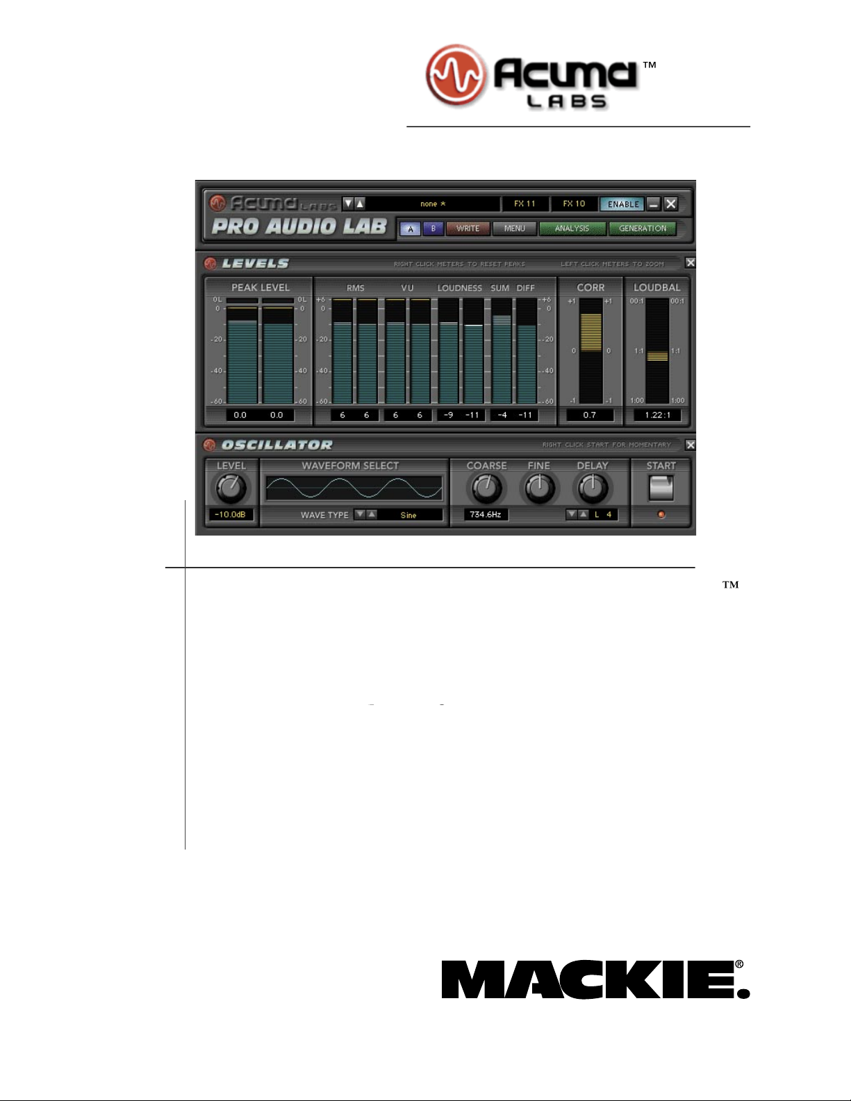
Thank you for purchasing Acuma Labs’ Pro Audio Lab. This is a precision audio
with editable frequencies and burst times. Last but not least, Pro Audio Lab provides
you with “dead-on” tuning references (down to semi-tones and cents) for guitar, bass,
capo, and 5 string bass.”
About Acuma Labs
Acuma Labs develops real-time embedded systems for professional audio applica-
tions to create high-quality products for the music and pro-audio industries. Acuma
The Mackie UFX card provides robust processing power for computation-heavy
About the D8B UFX Card
User’s Guide
Page 7
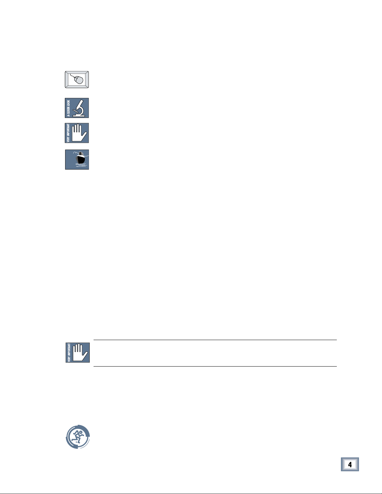
About Pro Audio Lab
Main Screen (with Levels and Oscillator open)
The main screen is an overview of the primary analysis meters and tone generation
Analysis and Generation, are located at the top of the screen and each has a pull-
As with all Mackie plug-ins, Pro Audio Lab can be routed as an “insert” or “auxil-
the effects return bank. Inserting is primarily used on the Master Outputs for concise
We will assume you have successfully installed a Mackie UFX card and Mackie Real
Time OS 3.0 software or greater. If you have encountered problems with the instal-
The plug-in is available from our website: www.mackie.com. Carefully follow the in-
Requirements
Obtaining the Plug-In
User’s Guide
Page 8
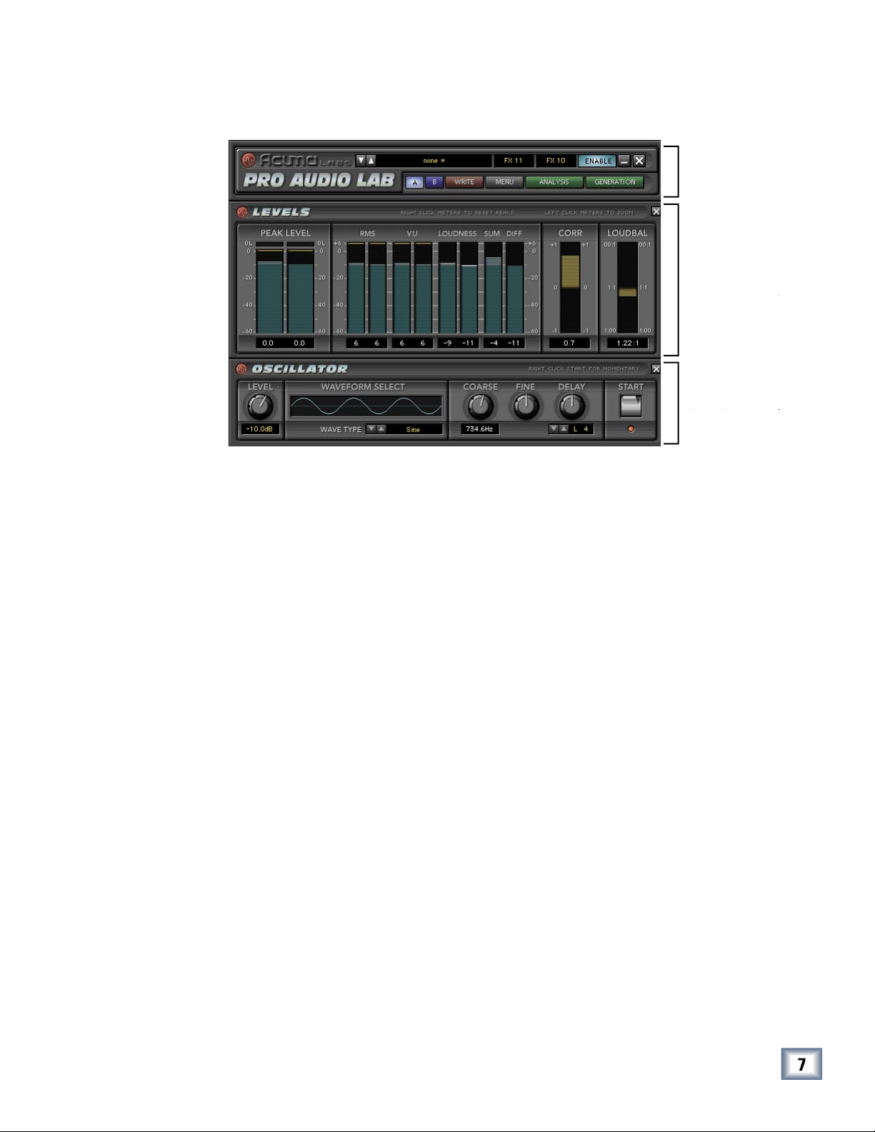
Unlock Procedure
bottom of the Licensing window, which is accessed from the Setup screen.
The 12-digit ESN is made from numbers 0–9 and letters A–F. It is unique to
the D8B processor, and is not the same as the serial number on the rear of
the control surface or CPU chassis.
You will also need your plug-in’s serial number.
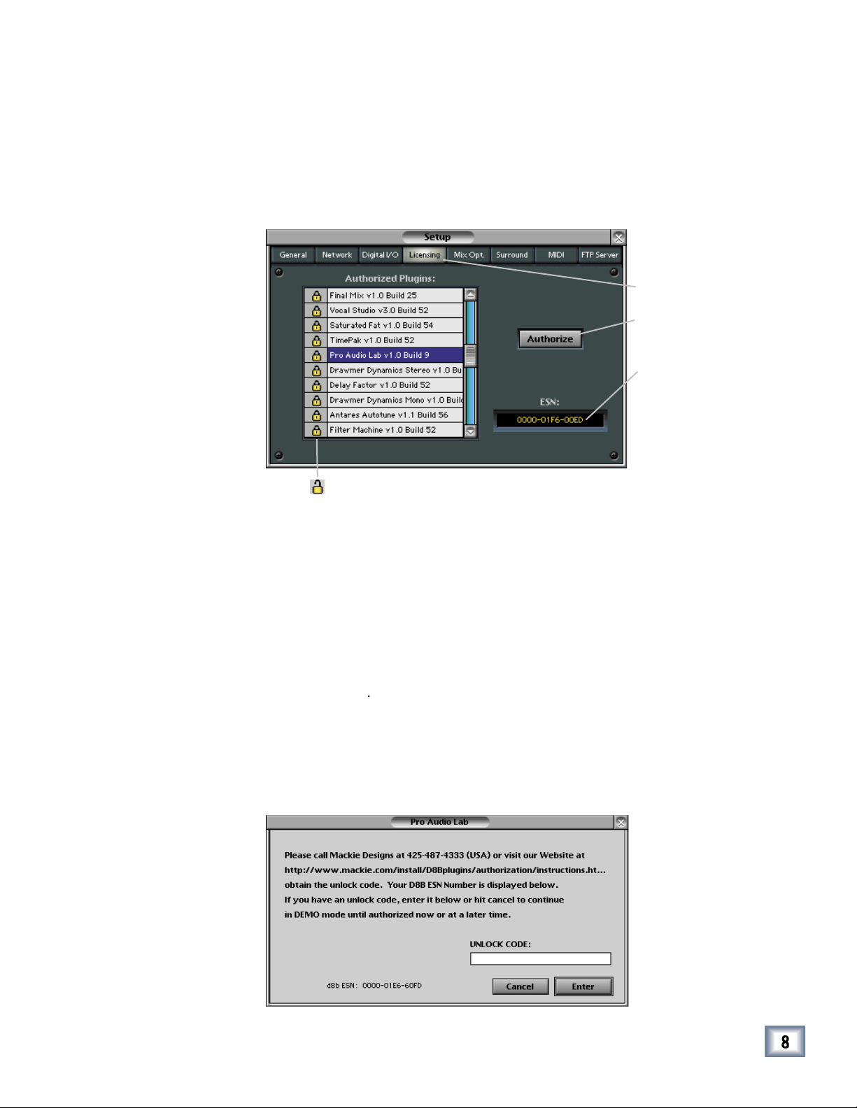
To obtain the unlock code, have the ESN and plug-in serial number ready.
Then you have two options:
• Log on to the Mackie plug-in authorization web page:
or
• Telephone Mackie Tech Support at 800-258-6883.
When you have obtained an unlock code, open the D8B Setup window, and
With your plug-in highlighted in the Licensing window, click
Authorize
your newly expanded console.
http://www.mackie.com/D8Bauthorize.htm
User’s Guide
Page 9
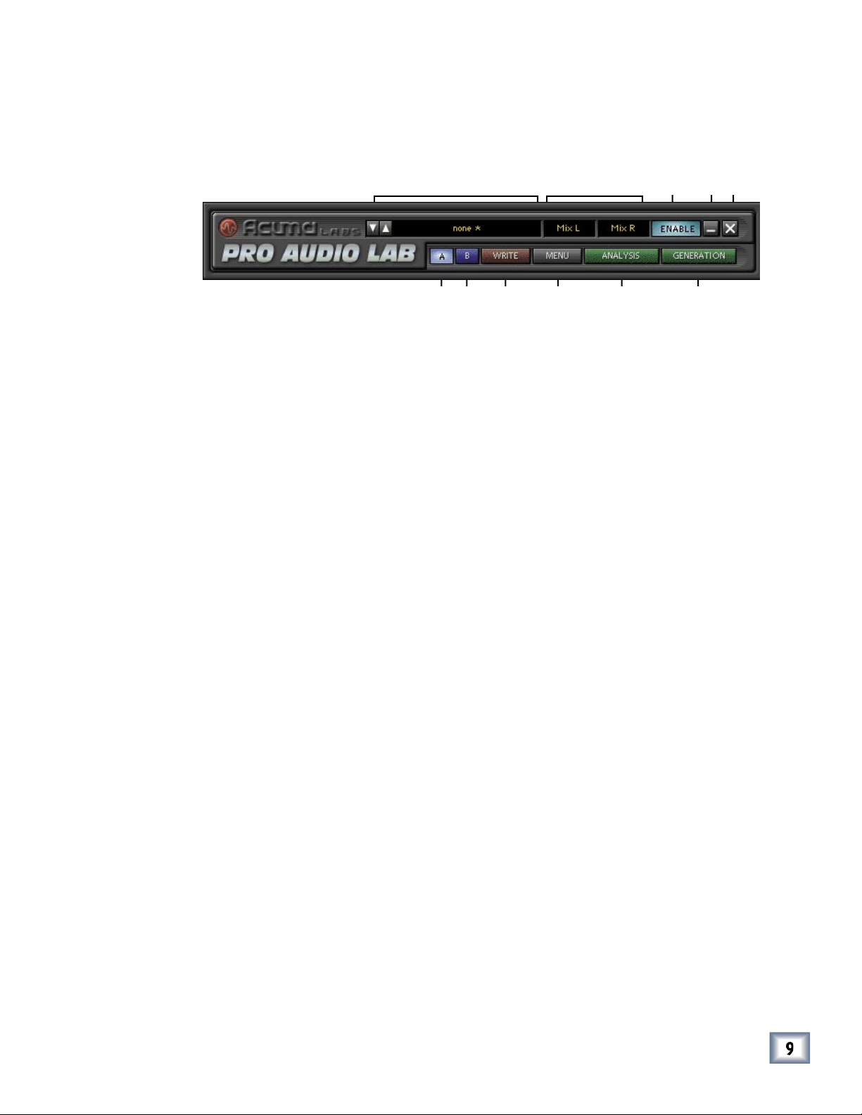
The Status Screen
Toggle the up/down arrows to select Factory Presets, or create your own and save
them to User Presets.
This switches Pro Audio Lab from the inactive state to active.
These buttons minimize Pro Audio Lab to a simpli ed version for better viewing of
the D8B screen. To switch from one screen to another, simply toggle between the
buttons to expand and shrink. Selecting X will hide Pro Audio Lab.
Write Button:
Write enables the D8B’s automation so that all of the changes that you make to the
be turned on in the automation section of the D8B (and automation must be out of
This drop-down menu enables familiar functions such as undo, redo, load, save, re-
Analysis:
The Analysis button opens a drop-down menu that lets you select from Levels,
The Generation button opens a drop-down menu that lets you select from a variety of
User’s Guide
Page 10
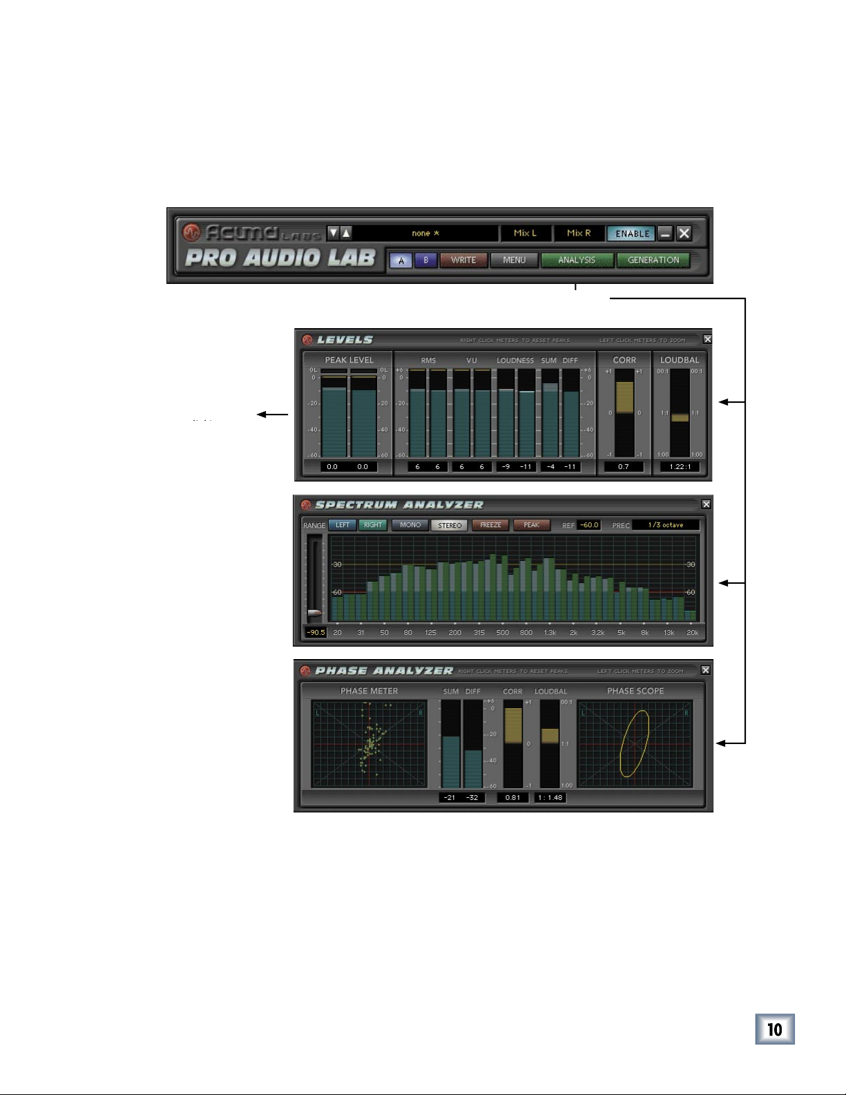
The Analysis Screens
The Levels, Spectrum Analysis, and Phase Analysis options are selected from the
Analysis drop-down menu found in the Status Screen. Only one option can be open at
User’s Guide
Page 11
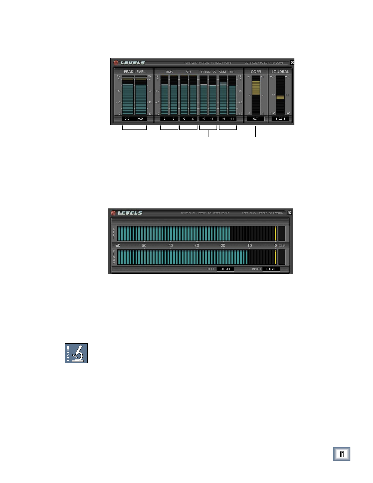
The Levels Screen
ter. Peak Level does not demonstrate the loudness of your program. The difference
between Peak and VU meters can be as much as 12 dB or 4x the apparent volume.
VU metering for the best results. The Overload Clip light responds to a single sample
User’s Guide
Page 12

with a reference signal. Neither a peak, nor an average, RMS is derived by squaring
then taking the square root of that value. Thus, RMS is a mathematical measure-
that is very helpful in describing the energy of a waveform in RMS values. RMS
wave such that a digital peak-to-peak signal (0 dBFS) will report 0 dB.
Peak to Peak
RMS
RMS = Peak / 2 = Peak x 0.0707
Peak = RMS x 2 = RMS x 1.414
User’s Guide
Page 13

VU Meter (Volume Unit Meter)
VU Meters (expanded view)
the levels of your program. There is often a 12 dB difference between peak level and
the level indicated by the VU meters. A VU meter is designed to have a relatively
the equal loudness contour graph. This type of audio measurement is very useful in
to the left/right of a stereo channel. For example, say you have two matching guitar
User’s Guide
Page 14

When using this application on the left and right masters, remember to turn off
the enable button in the Pro Audio Lab GUI to disable the Tone Generation, as you
There is no absolute measurement for how the ear hears frequency response and
Very Important:
With every 3 dB increase in output, double the ampli er and
The Sum and Difference meters analyze the sum of two input channels, and the dif-
when a stereo pair is summed to mono.
User’s Guide
Page 15

This clear and easy-to-read display is designed to help you understand the complex
the signals are perfectly in phase). 0 means that the two signals are not correlated.
This shows the A-weighted VU level relationship between two signals. The meter
User’s Guide
Page 16

Spectrum Analyzer
bands (1/6th octave) are supported in mono mode, and up to 31 bands (1/3rd octave)
The analyzer range enables you to adjust the viewing range of your signal between
–96 dB to –30 dB.
The mono button enables a mono view.
The freeze button will freeze the current frame to let you take a closer look at your
When the Peak button is enabled, each band’s meter displays its own peak, present-
that can be set anywhere from –60 dB to 0 dB. Use this to maintain a relativity refer-
User’s Guide
Page 17

This offers precision viewing ranges from 1 octave to 1/6 octave with additional
views in between. Click on the Precision window to open a drop-down menu to
The spectrum analyzer display has a rather soothing and mesmorizing effect,
which may trigger sleep and vivid dream sequences in certain pet hamsters and
We recommend that any furry animals in your studio are turned away
User’s Guide
Page 18

Phase Analyzer
The Phase Meter displays an X/Y plot of a set of raw Left and Right audio samples.
This results in a ‘swarm of bees’ type of display that is useful in visually determin-
A highly
correlated signal such as mono will display all the points in a vertical line.
correlated signal such as mono will display all the points in a vertical line.
A highly correlated signal such as mono, with a phase inversion on one side, will dis-
the left and right will display the points in a ‘random’ fashion. All other signals will
be a combination of these, where the power balance, correlation, and phase deter-
The Phase Scope represents a summary of what can be seen visually on the Phase
the determination of the phase relationships between the left and right channels.
User’s Guide
Page 19

The Generation Screens
Tone Generator options are selected from the Generation drop-down menu found in
the Status Screen. This is where you will nd a wide variety of oscillators and tuners
to suit any task. Only one option can be open at a time.
User’s Guide
Page 20

Noise Generator
This noise generator produces white and pink noise, and has independent burst/
This ratio refers to the percentage of burst vs. pause that is applied to the generated
This refers to the combined length of the burst and the pause. This increment can be
White noise is un ltered, unaltered thermal noise just like you hear when you turn
your ampli er all the way up to listen to the noise oor.
User’s Guide
Page 21

Slate Tone Generator
The familiar three-step oscillated tone sequences (like we used to hear at the be-
Tone Duration
Tone duration refers to the amount of tone vs. pause (no sound). These tones have
by grabbing the tone/ pause bar with your mouse.
The Burst/Pause Ratio refers to the percentage of burst compared to pause that is
between 0 seconds (off) and 100 seconds (full). To adjust the ratio, use your mouse
to select the up/down arrows, or scroll the numbers in the small window, or grab the
blue bar graphic and move it left or right.
Total Time (tone sequence)
Total Time refers to the combined length of tone and pause. Pause can be assigned
to any interval between 0 seconds (off) and 60 seconds. Use the mouse to select total
time using the up or down arrows or to scroll the digits.
Tone Select
This lets you choose the frequency of each tone from 16 Hz to 20.0 kHz. Choose
try standards, or customize your own. You can enable or disable individual tones by
User’s Guide
Page 22

The Oscillator
The oscillator has many uses in sound testing, as it can zero in on a speci c fre-
very apparent changes in tone quality.
Waveform Type
This lets you select the type of waveform to generate as your audio signal. The oscil-
three ‘square’ waveforms. The default is a sine wave, but you can select other wave-
With a range of 15.6 Hz to 20.2 kHz, the Course control enables you to “ball-park” a
Tip:
A good way to approach this is to set your Fine control to its default (control/
You can offset your signal, one sample at a time, by adjusting the Oscillator Delay to
to adjust the Delay knob or use the up/down arrows. This is useful for identifying
Tip:
Using the Delay feature in Pro Audio Lab does not adjust the delay in your signal.
tone burst for as long as you hold down the button.
User’s Guide
Page 23

The Piano Tuning Reference
The piano tuning reference is a very convenient tool which is useful for many studio
This one-octave keyboard lets you use your mouse to select the note or key to use as
Wave Select
This offers two separate waveforms that can be used as the tuning source tone. The
the addition of harmonics can often assist in tuning instruments such as bass or the
This offers a +/– semi-tone pitch shift to accommodate alternate instrument tunings.
window.
This raises or lowers a selected semi-tone up to + or – 50 cents. The default is zero.
A cent is a unit of a pitch interval equivalent to 1/100th of the semi-tone.)
User’s Guide
Page 24

The Guitar Tuning Reference
This offers an easy way to make sure your guitar player is in tune. It’s always a good
Tuning
This displays a (viewing only) preference of a pitched semi-tone, as it appears in the
This offers adjusted string tones for a selected capo position. The tuning (0 to +12)
Wave Select
This offers two separate waveforms that can be used as the tuning source tone. The
This offers a +/– semi-tone pitch shift to accommodate alternate instrument tunings.
This raises or lowers a selected semi-tone up to + or – 50 cents. The default is zero.
A cent is a unit of a pitch interval equivalent to 1/100th of the semi-tone.)
User’s Guide
Page 25

The Bass Tuning Reference
This offers an easy way to make sure that your bass player is in tune. It’s always a
Type
bass guitars have alternate tunings to accommodate alternate string con gurations.
The String Select plays the appropriate tones for the selected tunings.
This displays a (viewing only) preference of a pitched semi–tone, as it appears in the
the frets on the guitar neck
Wave Select
This offers two separate waveform options that can be used as the tuning source
tone. The squiggly line icon is a sine wave with three harmonics, the sine wave sym-
bol is a pure sine wave tone. It may be easier for some to tune to a pure sign wave
while the addition of harmonics can often assist in tuning instruments such as bass
This offers a +/– semi-tone pitch shift to accommodate alternate instrument tunings.
Adjusting this control will raise or lower your tone up to + or – 50 cents. The default
A cent is a unit of a pitch interval equivalent to 1/100th of the semi-tone.)
User’s Guide
Page 26

The A440 Tuning Reference
The A440 is the accepted standard tuning reference. It’s handy to have access to this
Wave Select
This offers two separate waveforms that can be used as the tuning source tone. The
A frequency range can be ne-tuned to zero on a reference tone by adjusting from
A cent is a unit of a pitch interval equivalent to 1/100th of the semi-tone.)
User’s Guide
Page 27

Con guring the Plug-In
After installing your UFX card, unlocking the plug-in, and booting up the D8B, all you
The following instructions are general for most plug-ins. Please note that the graph-
that contains the UFX card to which you want to assign the plug-in.
column, click a button and set it to mono or stereo, depending
column, select the plug-in from the drop-down menu. It
A plug-in can also be loaded from the Setup section on the console.
Assigning the Plug-in to a UFX Card
User’s Guide
Page 28

Assigning an Input Source to the Plug-in
button to select an input source. In the
The
ber and whether the effect output is mono or
The default state for all FX
A plug-in can also receive its input from a channel pre- or post-DSP insert,
the main stereo left and right bus, or Bus 1-8. When a plug-in is inserted in
this manner, its output is routed directly back into the channel.
you to daisy-chain two or more plug-ins in series.
To combine two or more plug-ins:
Assign the Destination (output) for the rst plug-in to its default FX
Assign the Input Source for the second plug-in to the FX Return that
the rst plug-in is routed to (Input Source/Plugin Chain/FX 1-16).
button to select where the plug-in’s output
from the associated plug-in drop-down assignment
in the Alert dialog box.
Warning:
Deactivating a plug-in erases all automation data for the plug-in.
Assigning a Destination for the Plug-in
Deactivating the Plug-in
User’s Guide
Page 29

Saving, Loading, and Resetting a Preset
To Save a Preset:
button.
to overwrite the le currently
to save to a new le name.
The Save Preset File As dialog box appears.
4. A default name for the preset is automatically displayed, such as Preset#1.
(default hard drive) or
to complete the operation.
To Load a Preset:
to choose the memory
button.
3. Select
to open a le. The Load Preset
4. Click
the le is on the internal
if
the le is on a
want to load.
to load the
User’s Guide
Page 30

To Reset the Plug-in:
button.
To Cut Plug-in Settings:
button.
The current settings are temporarily stored in the clipboard
The plug-in also reverts to its default state (it is reset).
To Copy Plug-in Settings:
button.
The current settings are temporarily stored in the clipboard
To Paste Plug-in Settings:
button.
The current settings are replaced with the settings in the clipboard memory. Settings
User’s Guide
Page 31

Automation and Snapshot Control
To write automation on a loaded plug-in:
AUTO TOUCH
button, then choose
the plug-in you wish to view from the page drop-down menu. This displays a list of
Parameters can be controlled from either the GUI plug-in graphic parameters (using
To automate the loading of a plug-in preset:
Plug-in settings are recalled as part of a console Snapshot, but may also
be recalled as Presets (patches). If you are recalling snapshots and presets, be aware that
Dynamic Real Time
Event Based
User’s Guide
Page 32

FX Routing
A pre- or post-DSP channel
When a channel insert point is selected, the plug-in output returns to the channel by
A plug-in channel insert assignment can be made from the Plugin Con guration win-
This assignment can also be made from the control surface and VFD by holding the
The Plug-in Con guration Window
User’s Guide
Page 33

Input Source
button and select an Aux input source. In
the example below, we have chosen the Aux 4 Bus.
AUX 4
control to adjust the input level to the plug-in.
Select an aux send before using the V-pot or GUI Control Pot on the mixer
You will see the plug-in’s input meter become active as you raise the mixer input
be accomplished from the console or GUI.
User’s Guide
Page 34

Pre-Fader and Post-Fader Auxiliary Sends
yellow bar.
buttons below the Aux knobs toggles be-
tween pre- and post-fader operation. Yellow indicates pre-fader, otherwise the aux is
User’s Guide
Page 35

The FX Return Channel
(49-72) and bring up faders one
with these channels.
on the keyboard).
User’s Guide
Page 36

Acuma Pro Audio Lab
 Loading...