

Page 1
OPT•24OPT•24
OPT•24
OPT•24OPT•24
Installation Guide
24-Channel 24-bit ADAT Optical I/O Card for the HDR24/96 and MDR24/96
Page 2
Important Safety Instructions
Introduction
1. Read instuctions — Read, understand and follow all safety and
operating instructions before using this Mackie product.
2. Retain Instructions — Keep these safety and operating
OPT•24
instructions for future reference.
3. Heed Warnings — Follow all warnings on this Mackie product
and in these operating instructions.
4. Disconnect the power source to the HDR24/96 before installing
the OPT•24 I/O Card.
5. Servicing — Do not attempt to service this Mackie product. All
servicing should be referred to the Mackie Service Department.
ATTENTION: The installation of this option requires opening the
HDR24/96 and handling sensitive electronic components. Anti-static
precautions
the unit. Damage caused to the unit due to improper installation or
handling of these components
If you do not feel capable of performing this installation, please
call Mackie Tech Support at 800-898-3211 to obtain a referral to
a service center that can perform the installation.
must
be taken in order to prevent potential damage to
will not be covered under warranty
Important: You must have
version 1.3 or higher of the
HDR24/96 or MDR24/96 OS in
order to use the OPT•24. Follow
the installation instructions with
the software upgrade to install
the new software.
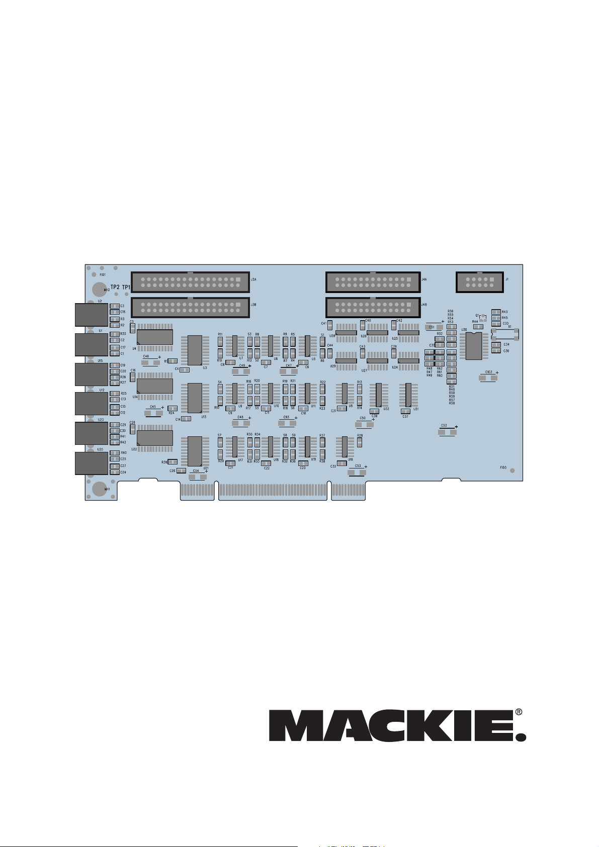
Thank you for choosing Mackie Designs for your
hard disk recording solution. The OPT•24 is a major
step forward in our continued support of the
HDR24/96 and MDR24/96 Hard Disk Recorders.
The OPT•24 provides 24 channels (8x3) of 24-bit
ADAT optical I/O. But what makes it especially
unique and valuable is that it doesn’t use any of the
three I/O slots provided for the analog and digital
I/O cards. Instead, it is installed in a PCI slot next to
the Sync card. Once installed, you have the added
flexibility of choosing between at least two different
input and output formats for your recorded audio.
For example, you can use three analog AIO•8 cards
to bring the audio into the HDR, and use the
OPT•24 to output the audio in 24-bit digital format.
Installing the OPT•24
.
Important: The OPT•24
contains static-sensitive
components. Anti-static
precautions must be taken before
opening the anti-static bag and
handling the OPT•24. Use an
anti-static wrist strap when performing this installation.
These are available at most computer supply stores.
The use of an anti-static mat is also recommended.
1) Turn off the Hard Disk Recorder and remove
the AC linecord from the socket on the rear
panel. We don’t want this to be a shocking
experience for you!
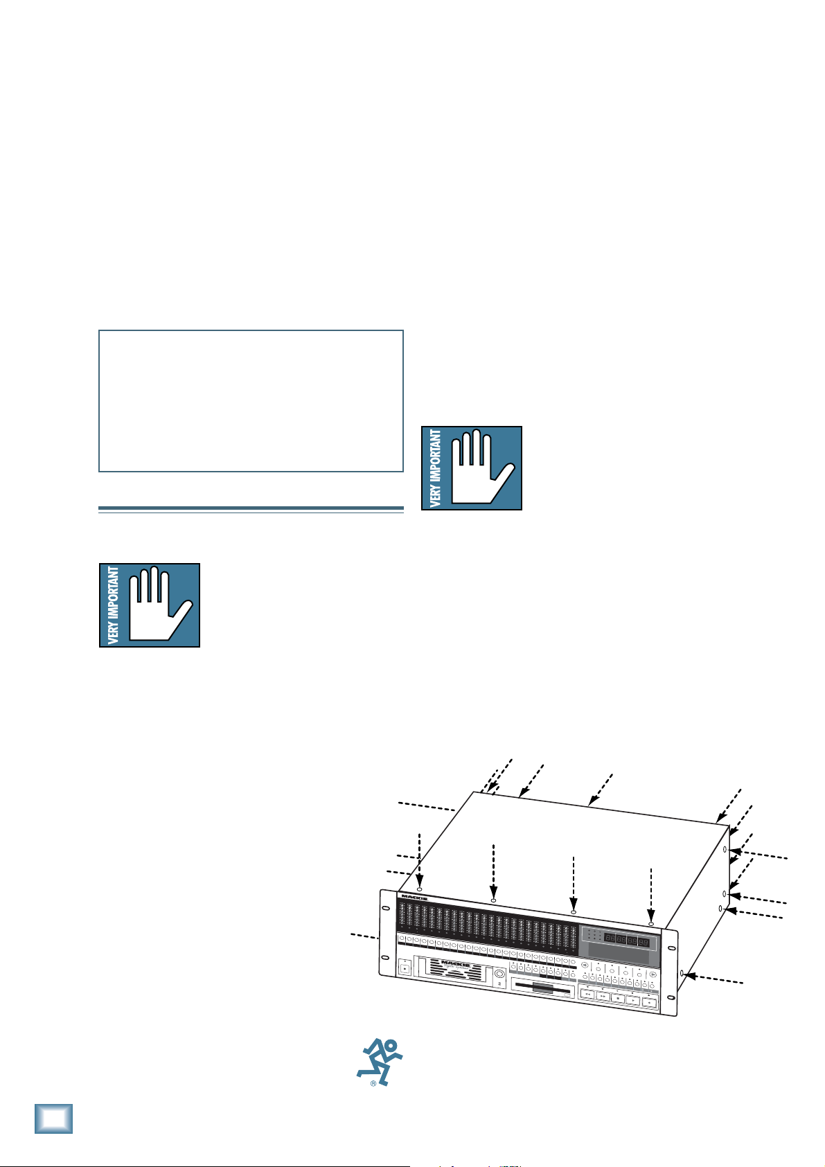
2) Remove 22 screws from the HDR24/96 cover
using a #2 Phillips screwdriver (4 screws
from the top panel, 4 screws from each side,
and 10 screws from the rear panel). These
screws are all one size.
2
4
T
R
A
C
K
/
2
4
B
I
O
L
2
4
7
1
0
1
5
2
0
2
5
3
0
3
5
4
0
5
0
21
R
E
CR
E
1
P
O
W
E
R
ON
Part No. 0002733 Rev. B 10/02
© 2002 Mackie Designs Inc. All rights reserved.
Printed in the U.S.A.
2
OPT•24
T
D
I
O
L
2
4
7
1
0
1
5
2
0
2
5
3
0
3
5
4
0
5
0
C
G
I
T
A
L
O
L
2
4
7
1
0
1
5
2
0
2
5
3
0
3
5
4
0
5
0
3
4
R
E
C
R
E
32
4
A
U
D
I
O
L
2
4
7
1
0
1
5
2
0
2
5
3
0
3
5
4
0
5
0
5
C
R
E
5
O
H
A
O
L
2
4
7
1
0
1
5
2
0
2
5
3
0
3
5
4
0
5
0
6
C
R
E
C
6
R
D
D
O
L
2
4
7
1
0
1
5
2
0
2
5
3
0
3
5
4
0
5
0
R
E
7
I
S
K
R
O
L
2
4
7
1
0
1
5
2
0
2
5
3
0
3
5
4
0
5
0
87
C
R
E
8
E
C
O
R
O
L
2
4
7
1
0
1
5
2
0
2
5
3
0
3
5
4
0
5
0
9
C
R
E
C
9
D
E
R
/
O
L
2
4
7
1
0
1
5
2
0
2
5
3
0
3
5
4
0
5
0
1
0
R
E
C
1
0
E
D
I
T
O
L
2
4
7
1
0
1
5
2
0
2
5
3
0
3
5
4
0
5
0
1
R
E
1
O
R
O
L
O
L
2
O
L
2
O
L
4
2
O
L
4
2
O
L
7
4
2
O
L
7
4
2
1
0
1
0
1
5
1
5
2
0
2
0
2
5
2
5
3
0
3
0
3
5
3
5
4
0
4
0
5
0
5
0
1
1
2
1
C
R
E
C
R
E
1
2
1
O
L
7
4
2
O
L
7
4
2
1
0
7
4
2
1
0
7
4
1
5
1
0
7
4
1
5
1
0
7
2
0
1
5
1
0
7
2
0
1
5
1
0
2
5
2
0
1
5
1
0
2
5
2
0
1
5
3
0
2
5
2
0
1
5
3
0
2
5
2
0
3
5
3
0
2
5
2
0
3
5
3
0
2
5
4
0
3
5
3
0
2
5
4
0
3
5
3
0
5
0
4
0
3
5
3
0
5
0
4
0
3
5
5
0
4
0
3
5
5
0
4
0
5
0
4
0
5
0
5
3
C
31
0
4
1
51
1
6
1
7
1
8
9
2
R
E
C
01
R
E
CR
E
C
R
E
CR
1
514
E
C
1
6
R
E
C
1
7
R
E
C
1
8
1
9
2
0
L
O
C
1
L
O
C
2
S
T
O
R
L
E
O
O
P
R
1
E
–
C
2
S
A
F
E
H
O
L
2
4
7
1
0
1
5
2
0
2
5
3
0
3
5
4
0
5
0
2
R
2
A
I
N
P
D
O
L
2
4
7
1
0
1
5
2
0
2
5
3
0
3
5
4
0
5
0
1
2
E
C
R
1
L
L
A
U
T
IN
R
2
O
L
2
4
7
1
0
1
5
2
0
2
5
3
0
3
5
4
0
5
0
2
E
C
R
E
22
2
U
T
O
A
U
P
U
T
T
A
K
4
HIGH RESOLUTION AUDIO
/
9
O
L
2
4
7
1
0
1
5
2
0
2
5
3
0
3
5
4
0
5
0
3
2
42
C
R
E
C
3
2
4
T
O
T
C
O
D
E
C
H
A
S
E
6
44.1/48/96K SAMPLE RATES
4
H
4
.
O
1
k
U
R
S
4
8
k
M
9
6
IN
k
U
T
E
S
S
E
C
O
V
A
R
I
E
R
R
O
R
PLA
D
E
D
E
L
E
T
E
L
A
S
TP
T
R
REWIND
N
D
1
6
T
A
C
S
B
IT
2
4
C
C
L
PRO
AVAIL
S
E
L
E
K
R
O
FAST FWD
F
R
A
M
JECT:
RIVE
B
A
E
S
BARS
BEATS
TICKS
Lit
tl
e lo
: Pla
ve
ylist
:
1
C:I
ntern
: 01:
al
35:0
0
S
E
L
E
C
T
S
E
L
E
C
T
S
E
L
E
C
T
C
K
U
PD
IS
K
U
T
I
L
S
Y
S
T
E
M
D
I
G
II/
O
S
Y
N
C
D
E
C
I
N
C
STOP
PLAY
RECORD
B
IT
O
C
K
YLIST
C
T
J
E
C
T
3) Remove the cover by lifting it up at the back
and pulling up and away from the front of the
unit.
Page 3
4) Remove the blank cover plate for the ACC1 slot (next to the SYNC card) by removing 1 Phillipshead screw. Save the screw for installing the OPT•24.
4) Remove Screw and
ACC1 Slot Cover Plate
REAR PANEL
REAR PANEL
© 2000
MACKIE DESIGNS. ™
®
Installation Guide
FRONT PANEL
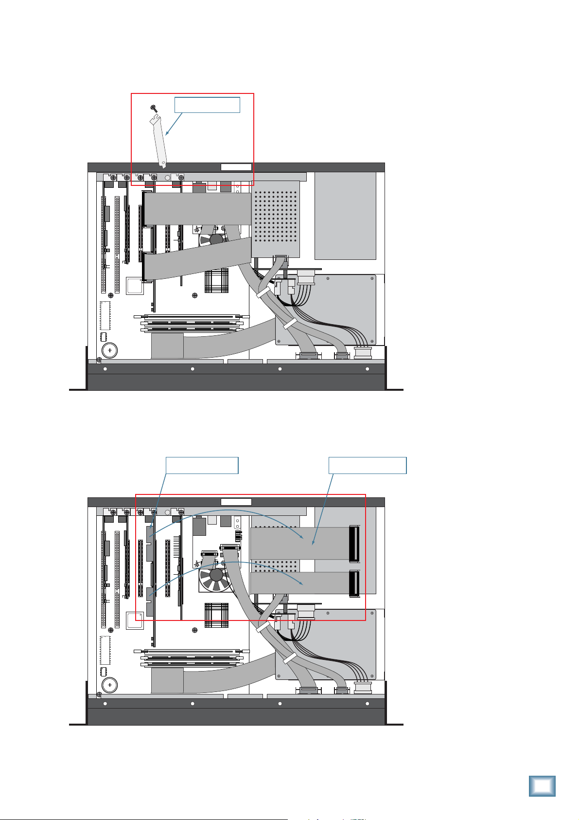
5) Unplug the 2 ribbon cables from the Sync card. Squeeze the tabs on the sides of the connectors and
gently wiggle from side to side to release them from their sockets.
5A) Unplug Ribbon Cables
from Sync Card
REAR PANEL
REAR PANEL
© 2000
MACKIE DESIGNS. ™
®
5B) Pull Ribbon Cables back
and out of the way
FRONT PANEL
Installation Guide
3
Page 4

6) Unplug both ends of the COM cable (040-383-00), located between the front panel Display board (A)
and the Card Cage board (B). Cable ties hold the COM cable in place. Leave the cable inside the
HDR24/96 in case the OPT•24 is ever removed and the COM cable needs to be reconnected.
OPT•24
7) Connect the 2 short/fat ribbon cables (supplied) to the 2 bottom connectors (J3B and J4B, furthest
from the edge) on the OPT•24. The connectors have a keying tab in the center so they can’t be
plugged in wrong. It doesn’t matter which end of the ribbon cables you connect to the OPT•24.
6) Remove the COM Cable
REAR PANEL
REAR PANEL
© 2000
MACKIE DESIGNS. ™
®
from the Display Board (A)
and the Card Cage Board (B)
B
040-383-00
A
FRONT PANEL
J3B J4B
8) Connect the 2 ribbon cables that you removed from the Sync card to the 2 top connectors (J3A and
J4A, closest to the edge) on the OPT•24. They will click in place when properly inserted.
8) Connect 2 Ribbon Cables
to OPT¥24 Board
REAR PANEL
REAR PANEL
OPT¥24 Board
© 2000
MACKIE DESIGNS. ™
®
4
OPT•24
FRONT PANEL
Page 5

9) Install the OPT•24 into the ACC1 PCI slot by carefully aligning the card’s gold-plated connector
edge to the PCI slot on the motherboard and pushing down gently but firmly until the card is fully
seated into the slot. It may help to gently rock the board front to back until the board is completely
seated.
Note: Make sure the loose connector ends are pointing up so they can be accessed for step 11.
Installation Guide
9) Install OPT•24 Board
into the ACC1 PCI slot
10) Install Screw into
the OPT•24 bracket
REAR PANEL
REAR PANEL
© 2000
MACKIE DESIGNS. ™
®
FRONT PANEL
10) Install the screw that you removed from the blank cover plate to secure the OPT•24 to the HDR chassis.
11) Connect the short ribbon cables from the OPT•24 card to the adjacent Sync card by folding them over the
top of the Sync card (see illustration below and on next page).
11) Connect the 2 short ribbon
cables to the Sync Card
REAR PANEL
REAR PANEL
© 2000
MACKIE DESIGNS. ™
®
FRONT PANEL
Installation Guide
5
Page 6

OPT•24
Front view of ribbon cable connections between the
Sync Card and the OPT•24
12) Install the supplied replacement COM cable.
a. Install the center connector to the Card Cage board.
b. Install the shorter end to the front panel Display board.
c. Install the longer end to the OPT•24 board.
OPT•24
SYNC CARD
REAR PANEL
REAR PANEL
VIDEO CARD
12a) Install the replacement COM Cable:
Center connector to Card Cage Board
© 2000
12c) Longer end to
OPT•24 Board
MACKIE DESIGNS. ™
®
FRONT PANEL
13) Replace the cover, reinstall the screws, and
you’re ready to go!
12b) Shorter end to Front
Panel Display Board
6
OPT•24
Page 7

Selecting the OPT•24 I/O
This is done in the same way that you setup and
configure the other I/O cards—in the Digital I/O
Setup window (or by pressing the Digi-I/O button on
the front panel).
Installation Guide
To select the OPT•24 from the front panel:
1. Press Digi-I/O to enter the Digital I/O Card
Setup screen.
DISK UTIL SYSTEM DIGI-I/O SYNC DEC
2. Select In. The Setup Tape Inputs screen
shows you the current settings for each of the
three I/O cards.
DIGITAL I/O Card Setup
Stat Rate
In Out Bits Convert
3. Press the Select button corresponding to each
I/O card and toggle the selection to the
desired input source.
4. The OPT•24 outputs are always active, so no
configuration is necessary for the outputs.
5. When done, press the Digi-I/O button to exit
the menu.
To select the OPT•24 from the screen
(HDR24/96 only):
1. Select Setup from the Windows menu and
click the Digital I/O icon. The Digital I/O
Setup dialog box shows you the current
settings for each of the three I/O cards.
2. Click the Input pulldown menu and select the
input source you want to use for each I/O
card.
IN 17-24
OUT 17-24
IN 9-16
OUT 9-16
IN 1-8
OUT 1-8
OPT•24 Inputs and Outputs
3. The OPT•24 outputs are always active, so no
configuration is necessary for the outputs.
“Mackie,” the “Running Man” figure, and “OPT•24”
are trademarks or registered trademarks of Mackie
Designs Inc. All other brand names mentioned are
trademarks or registered trademarks of their
respective holders, and are hereby acknowledged.
© 2002 Mackie Designs Inc.
All Rights Reserved.
Printed in the U.S.A.
Installation Guide
7
Page 8

16220 Wood-Red Rd. NE • Woodinville, WA 98072 • USA
US & Canada: 800/898-3211
Europe, Asia, Central & South America: 425/487-4333
Middle East & Africa: 31-20-654-4000
Fax: 425/487-4337 • www.mackie.com
E-mail: sales@mackie.com
 Loading...