

Mackie Onyx 24-4, Onyx 32-4 Owner's Manual

PREMIUM LIVE ANALOG MIXERS
80 Series
w/PERKINS EQ & ONYX MIC PREAMPS
OWNER’S MANUAL
Important Safety Instructions
1. Read these instructions.
2. Keep these instructions.
3. Heed all warnings.
4. Follow all instructions.
5. Do not use this apparatus near water.
6. Clean only with a dry cloth.
ONYX 4•Bus
7. Do not block any ventilation openings. Install in accordance with the
manufacturer’s instructions.
8. Do not install near any heat sources such as radiators, heat registers,
stoves, or other apparatus (including amplifiers) that produce heat.
9. Do not defeat the safety purpose of the polarized or grounding-type
plug. A polarized plug has two blades with one wider than the other.
A grounding-type plug has two blades and a third grounding prong.
The wide blade or the third prong are provided for your safety. If the
provided plug does not fit into your outlet, consult an electrician for
replacement of the obsolete outlet.
10.
Protect the power cord from being walked on or pinched particularly at
plugs, convenience receptacles, and the point where they exit from the
apparatus.
11.
Only use attachments/accessories specified by the manufacturer.
12.
Unplug this apparatus during lightning storms or when unused for long
periods of time.
13.
Refer all servicing to qualified service personnel. Servicing is required
when the apparatus has been damaged in any way, such as powersupply cord or plug is damaged, liquid has been spilled or objects have
fallen into the apparatus, the apparatus has been exposed to rain or
moisture, does not operate normally, or has been dropped.
14.
This apparatus shall not be exposed to dripping or splashing, and no
object filled with liquids, such as vases or beer glasses, shall be placed
on the apparatus.
15.
Do not overload wall outlets and extension cords as this can result in a
risk of fire or electric shock.
16.
This apparatus has been designed with Class-I construction and must
be connected to a mains socket outlet with a protective earthing connection (the third grounding prong).
CAUTION AVIS
RISK OF ELECTRIC SHOCK. DO NOT OPEN
RISQUE DE CHOC ELECTRIQUE. NE PAS OUVRIR
CAUTION: TO REDUCE THE RISK OF ELECTRIC SHOCK DO NOT REMOVE COVER (OR BACK)
NO USER-SERVICEABLE PARTS INSIDE. REFER SERVICING TO QUALIFIED PERSONNEL
ATTENTION: POUR EVITER LES RISQUES DE CHOC ELECTRIQUE, NE PAS ENLEVER LE COUVERCLE.
AVIS: POUR EVITER LES RISQUES D'INCENDIE OU D'ELECTROCUTION, N'EXPOSEZ PAS CET ARTICLE
AUCUN ENTRETIEN DE PIECES INTERIEURES PAR L'USAGER.
CONFIER L'ENTRETIEN AU PERSONNEL QUALIFIE.
A LA PLUIE OU A L'HUMIDITE
The lightning flash with arrowhead symbol within an equilateral triangle is
intended to alert the user to the presence of uninsulated "dangerous
voltage" within the product's enclosure, that may be of sufficient magnitude
to constitute a risk of electric shock to persons.
Le symbole éclair avec point de flèche à l'intérieur d'un triangle équilatéral
est utilisé pour alerter l'utilisateur de la présence à l'intérieur du coffret de
"voltage dangereux" non isolé d'ampleur suffisante pour constituer un risque
d'éléctrocution.
The exclamation point within an equilateral triangle is intended to alert the
user of the presence of important operating and maintenance (servicing)
instructions in the literature accompanying the appliance.
Le point d'exclamation à l'intérieur d'un triangle équilatéral est employé
pour alerter les utilisateurs de la présence d'instructions importantes pour le
fonctionnement et l'entretien (service) dans le livret d'instruction
accompagnant l'appareil.
17.
This apparatus has been equipped with a rocker-style AC mains power
switch. This switch is located on the rear panel and should remain
readily accessible to the user.
18.
The MAINS plug or an appliance coupler is used as the disconnect
device, so the disconnect device shall remain readily operable.
19. NOTE: This equipment has been tested and found to comply with
the limits for a Class B digital device, pursuant to part 15 of the FCC
Rules. These limits are designed to provide reasonable protection
against harmful interference in a residential installation. This equipment generates, uses, and can radiate radio frequency energy and, if
not installed and used in accordance with the instructions, may cause
harmful interference to radio communications. However, there is no
guarantee that interference will not occur in a particular installation. If
this equipment does cause harmful interference to radio or television
reception, which can be determined by turning the equipment off and
on, the user is encouraged to try to correct the interference by one or
more of the following measures:
• Reorientorrelocatethereceivingantenna.
• Increasetheseparationbetweentheequipmentandthereceiver.
• Connecttheequipmentintoanoutletonacircuitdifferentfrom
that to which the receiver is connected.
• Consultthedealeroranexperiencedradio/TVtechnicianforhelp.
CAUTION: Changes or modifications to this device not expressly
approved by LOUD Technologies Inc. could void the user's authority to
operate the equipment under FCC rules.
20. This apparatus does not exceed the Class A/Class B (whichever is
applicable)
limits for radio noise emissions from digital apparatus as
set out in the radio interference regulations of the Canadian Department
of Communications.
ATTENTION — Le présent appareil numérique n’émet pas de bruits
radioélectriques dépassant las limites applicables aux appareils
numériques de class A/de class B (selon le cas) prescrites dans le
réglement sur le brouillage radioélectrique édicté par les ministere des
communications du Canada.
21.
Exposure to extremely high noise levels may cause permanent hearing
loss. Individuals vary considerably in susceptibility to noise-induced
hearing loss, but nearly everyone will lose some hearing if exposed to
sufficiently intense noise for a period of time. The U.S. Government’s
Occupational Safety and Health Administration (OSHA) has specified
the permissible noise level exposures shown in the following chart.
According to OSHA, any exposure in excess of these permissible limits
could result in some hearing loss. To ensure against potentially dangerous exposure to high sound pressure levels, it is recommended that all
persons exposed to equipment capable of producing high sound pressure levels use hearing protectors while the equipment is in operation.
Ear plugs or protectors in the ear canals or over the ears must be worn
when operating the equipment in order to prevent permanent hearing
loss if exposure is in excess of the limits set forth here:
Duration,
per day in
hours
8 90
6 92
4 95
3 97
2 100
1.5 102
1 105
0.5 110
0.25 or less 115
Sound Level
dBA, Slow
Response
Typical Example
Duo in small club
Subway Train
Veryloudclassicalmusic
Greg and Ben screaming at Troy about deadlines
Loudest parts at a rock concert
Correct disposal of this product. This symbol indicates that this product should not be disposed of with your household waste, according to the WEEE Directive (2012/19/EU) and your national law. This product
should be handed over to an authorized collection site for recycling waste electrical and electronic equipment (EEE). Improper handling of this type of waste could have a possible negative impact on the environment and
human health due to potentially hazardous substances that are generally associated with EEE. At the same time, your cooperation in the correct disposal of this product will contribute to the effective usage of natural
resources. For more information about where you can drop off your waste equipment for recycling, please contact your local city office, waste authority, or your household waste disposal service.
2
ONYX 4•Bus

Table of Contents
Introduction ................................................................................................................4
Getting Started ..........................................................................................................5
Zero the Controls .......................................................................................................................................5
Connections .................................................................................................................................................5
Set the Levels ..............................................................................................................................................5
Instant Mixing .............................................................................................................................................5
Hookup Diagrams ..................................................................................................... 6
Onyx 4•Bus Features ...............................................................................................10
Mono Channel Strips ...............................................................................................................................10
Stereo Channel Strips .............................................................................................................................13
Matrix, Compressor, and Metering Section ...................................................................................... 15
Owner’s Manual
Phones/Monitor, Solo, Mono, and Talkback Section ....................................................................17
Auxiliary Section ......................................................................................................................................18
Group Section .......................................................................................................................................... 20
Rear Panel ...................................................................................................................................................21
Appendix A: Service Information ........................................................................25
Troubleshooting .......................................................................................................................................25
Repair .........................................................................................................................................................26
Appendix B: Connections ......................................................................................27
Appendix C: Technical Info .................................................................................. 30
Onyx 4•Bus Specifications ....................................................................................................................30
Onyx 4•Bus Dimensions .........................................................................................................................31
Onyx 4•Bus Block Diagram ....................................................................................................................32
Onyx 4•Bus Gain Structure Diagram ................................................................................................. 34
Onyx 4•Bus Limited Warranty .............................................................................35
Don’t forget to visit our website at www.mackie.com for more
information about this and other Mackie products.
Part No. SW0600 Rev. E 12/13
©2006-2013 LOUD Technologies Inc. All Rights Reserved.
Owner’s Manual
3

Introduction
HOW TO USE THIS MANUAL
Thank you for choosing a Mackie Onyx 4•Bus profes-
sional live mixing console. The Onyx 4•Bus mixers fea-
ture all-new analog circuitry and the latest technologies
for live sound reinforcement in a durable, road-worthy
package.
The Onyx 4•Bus mixing consoles replace the legend-
ary SR24•4 and SR32•4 VLZ PRO mixers. The new Onyx
ONYX 4•Bus
versions of these mixers maintain the same physical
size, channel count and features of the originals, while
adding a variety of new and improved features.
The Onyx 4•Bus consoles are equipped with our new
premium precision-engineered, studio-grade Onyx mic
preamps. Mackie is renowned for the high-quality mic
preamps used in our mixers, and the Onyx mic pre’s are
better than ever, with specifications rivaling expensive
stand-alone boutique mic preampliers.
Each mono channel strip features an individual phantom power switch, low-cut filter, mic input pad, pre-EQ
channel insert, and an all new four-band EQ design with
sweepable mids and EQ bypass switch.
All mono channels have six Aux sends, Pan, Mute, PFL
Solo, 100 mm Fader, Group and Main Mix assign, and
four signal-level indicators. In addition, balanced direct
outputs are provided on DB-25 connectors (eight channels per connector) for multitrack recording.
The master section features two Stereo Returns, six
Master Aux sends, four Group Masters, a 6x2 Matrix, a
Phones/Monitor section, and a Talkback section with
routing switches that allow you to communicate through
the Aux Sends and the L/R mix.
A new feature with the Onyx 4•Bus mixers is an analog
stereo compressor/limiter that can be inserted at the output of the L/R main mix, or the Group 1/2 or 3/4 outputs.
We know that many of you can’t wait to get your new
mixing console hooked up, and you’re probably not going
to read the manual rst (sigh!). So the next section is a
Quick-Start Guide to help you get the mixer set up fast
so you can start using it right away. Right after that are
the ever popular hook-up diagrams that show typical
mixer setups for live sound, recording and mixdown.
Then, when you have time, read the Features Descrip-
tion section. This describes every knob, button, and
connection point on the Onyx 4•Bus, roughly following
the signal flow through the mixer.
Throughout this section you’ll find illustrations with
each feature numbered. If you want to know more about
a feature, simply locate it on the appropriate illustration, notice the number attached to it, and find that
number in the nearby paragraphs.
This icon marks information that is
critically important or unique to the
Onyx 4•Bus. For your own good, read
them and remember them. They will
be on the final test.
This icon leads you to in-depth
explanations of features and practical tips. While not mandatory, they
usually have some valuable nugget of
information.
A PLUG FOR THE CONNECTOR SECTION
Appendix B is a section on connectors: XLR connectors, balanced connectors, unbalanced connectors, and
special hybrid connectors.
More resources on our website at www.mackie.com.
Please write your serial number here for future
reference (i.e., insurance claims, tech support,
return authorization, etc.)
Purchased at:
Date of purchase:
4
ONYX 4•Bus
Click on Support to nd answers to many of your questions. The FAQ (Frequently Asked Questions) section is
lled with answers to many of the questions our Techni-
cal Support staff has fielded over the years.
Check out the glossary for explanations of many of the
pro-audio terms used in our manuals.

Getting Started
READ THIS PAGE!!
Even if you’re one of those people
who never read manuals, all we ask
is that you read this page now before
you begin using the Onyx 4•Bus.
You’ll be glad you did!
Zero the Controls
1. Turn down the channel GAIN, AUX, and Fader controls, and center the channel EQ and PAN controls.
2. Set all push button switches to their “out” positions.
3. In the Master section, turn all the rotary knobs
“down,” the switches “out,” and the faders down.
4. Turn the POWER switch off.
Connections
If you already know how you want to connect the Onyx
4•Bus mixing console, go ahead and connect the inputs
and outputs the way you want them. If you just want to
get sound through the mixer, follow these steps:
1. Plug a microphone or other signal source into channel 1’s MIC or LINE input [73/74].
2. Plug in the detachable linecord, connect it to an AC
outlet, and turn on the Onyx 4•Bus’ POWER switch
[90].
3. Connect cables from the Onyx 4•Bus’ MAIN OUTS
[82] (XLR connectors or 1/4" TRS connectors on
the rear panel) to your amplifier or active speakers.
4. Hook up speakers to the amp and turn it on. If the
amplifier has level controls, set them however the
manufacturer recommends (usually all the way up).
output. Be sure that the volume of the input source
is the same as it would be during normal use. If it
isn’t, you might have to readjust these levels during
the middle of the set.
3. Adjust the channel’s GAIN [4] control so that the
LEDs on the Left MAIN MIX meter stay around “0”
and never go higher than “+10.”
4. If you’d like to apply some EQ, do so now and return
to step 3. Remember to push in the EQ IN/OUT
[11] switch or the EQ controls won’t do anything.
5. Disengage that channel’s PFL solo switch.
6. Repeat for each channel.
Instant Mixing
1. Leave the microphone plugged into channel 1 and
connect a keyboard, guitar or other instrument to
channel 2. Be sure to “Set the Levels” for channel 2
as described above.
To get sound out of the speakers, push in the MAIN
2.
MIX assign switch [17] next to the faders on chan-
1 and 2, turn up channel 1 and 2 faders [15] to
nels
the “U” mark and slowly turn up the MAIN MIX [72]
fader to a comfortable listening level.
3. Sing and play. You’re a star! Adjust the faders for
channels 1 and 2 to bring your voice and your
instrument up and down to create your own mix.
Other Nuggets of Wisdom
• For optimum sonic performance, the channel and
MAIN MIX faders should be set near the “U” (unity
gain) markings.
• Always turn the MAIN MIX faders, GROUP faders,
and MONITOR knob down before making connec-
tions to and from your Onyx 4•Bus.
• When you shut down your equipment, turn off the
amplifiers first. When powering up, turn on the
amplifiers last.
Owner’s Manual
Set the Levels
To set the channel GAIN controls, it’s not even necessary to hear what you’re doing at the outputs of the
mixer. If you want to listen while you work, plug headphones into the PHONES jack [46] on the front panel,
then set the PHONES knob [47] about one-quarter of
the way up and the SOLO LEVEL [49] about halfway up.
The following steps must be performed one channel at
a time.
1. Push in the channel’s PFL [18] solo switch.
2. Play something into the selected input. This could
be an instrument, a singing or speaking voice, or
a line input such as a CD player or tape recorder
• Never listen to loud music for prolonged periods.
Please see the Safety Instructions on page 2 for
information on hearing protection.
• Save the shipping box! You may need it someday,
and you don’t want to have to pay for another one.
That’s it for the “Getting Started” section. Next comes
the “Hookup” section that shows you some typical ways
that you might use the Onyx 4•Bus in real applications.
After that, take the grand tour of the mixer, with descriptions of every knob, button, input, and output. We
encourage you to take the time to read all of the feature
descriptions, but at least you know it’s there if you have
any questions.
Owner’s Manual
5
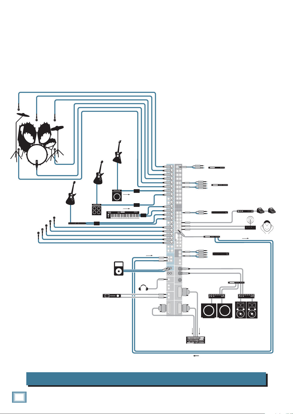
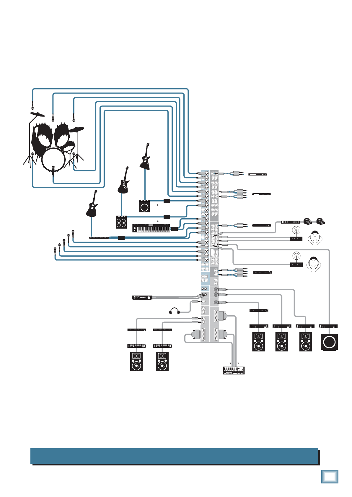
Hookup Diagrams
ONYX 4•Bus
Bass Guitar
This hookup diagram demonstrates how you can
make a live multitrack recording using the DIRECT
OUTs. The DIRECT OUTs provide an analog balanced
direct output for each channel, pre-EQ. The Matrix
outputs are used to create a stereo recording for
backup.
Aux Send 4 is used for stage monitors, and a graphic
EQ is connected to the Aux 4 Insert jack, serving as
a dedicated in-line EQ for the monitors.
5 and 6 are used to drive a stereo
IEM system. Aux
Aux Sends
Send 3 drives a stereo effects processor, whose stereo
signal is returned via the Stereo Returns jacks.
Vocal Mics
Electric Guitar
Electric Guitar
Stereo Guitar Effects
Guitar Amp
DI Box
Keyboard or Synth
Stereo Recorder
Bass Amp
MP3 Player
Line Out
Line Out
In (record)
DI Box
DI Box
DI Box
Headphones
1
2
3
4
5
6
7
8
9
10
11
12
13
14
15
16
17
18
19
20
21 22
23 24
L
1
R
L
L
L
R
A
B
1
2
3
4
5
6
7
8
9
10
11
CHANNEL INPUTS
12
13
14
15
16
17
18
19
20
STEREO RETURNS
L
2
R
IN-TAPE-OUT
R
R
PHONES
OUT
MONTIOR
OUT
MATRIX
OUT
DIRECT OUT
1-8
1
11
2
12
3
13
4
14
5
15
6
16
CHANNEL INSERTS
7
17
8
18
19
9
10
20
1
4
2
5
3
6
AUX SEND INSERTS
1
4
2
5
AUX SEND
3
6
1
3
INSERTS
2
4
GROUP OUT
1
3
2
4
GROUP OUTS
L
MAIN
R
INSERTS
L
OUT
MAIN
R
OUT
MAIN
OUT
MONO
17-24
DIRECT OUT
9-16
DIRECT OUT
Mono Compressor
In
Out
In
Stereo Compressor
Out
In
Out
In
Out
Multi Effect
Processor
In
Out
In
Out
Stereo Power
Amplifier
Mono EQ
Stereo EQ
Stereo Crossover
Stage Monitors
Mono Power
Amplifier
Stereo In-Ear Monitor
System (IEM)
Stereo Power
Amplifier
PA Speaker
Digital Multitrack
Hard Disk Recorder
Subwoofers
SELECT SELECT SELECT SELECT
Onyx 24•4 Live Club Mix and Multitrack Recording
6
ONYX 4•Bus
Bass Guitar
Owner’s Manual
Vocal Mics
Electric Guitar
Electric Guitar
Stereo Guitar Effects
Guitar Amp
DI Box
Bass Amp
Keyboard or Synth
Listen WedgeTalkback Mic
Line Out
Line Out
DI Box
DI Box
Mono Power
Amplifier
DI Box
Mono Compressor
1
1
1
11
2
2
2
12
3
3
3
13
4
4
14
4
5
5
5
15
6
6
6
16
7
CHANNEL INSERTS
7
7
17
8
8
8
18
9
19
9
9
10
10
20
10
11
11
CHANNEL INPUTS
12
12
1
4
13
13
2
5
14
14
3
6
AUX SEND INSERTS
15
1
4
15
16
2
5
16
AUX SEND
3
6
17
17
18
18
1
3
19
INSERTS
19
2
4
GROUP OUT
20
1
3
20
2
4
21 22
GROUP OUTS
23 24
L
STEREO RETURNS
MAIN
R
INSERTS
L
L
1
2
L
R
R
OUT
MAIN
R
IN-TAPE-OUT
R
L
OUT
MAIN
L
R
PHONES
OUT
OUT
MONO
MONTIOR
OUT
L
R
TALKBACK
17-24
MATRIX
OUT
MIC
A
DIRECT OUT
B
DIRECT OUT
1-8
9-16
DIRECT OUT
In
Out
In
Out
In
Out
In
Out
Stereo Compressor
Mono EQ
Mono Power
Amplifier
Mono Power
Amplifier
Stereo In-Ear Monitor
System (IEM)
Mono Power
Amplifier
Mono Power
Amplifier
Stage Monitor
Stage Monitor
Stage Monitor
Stage Monitor
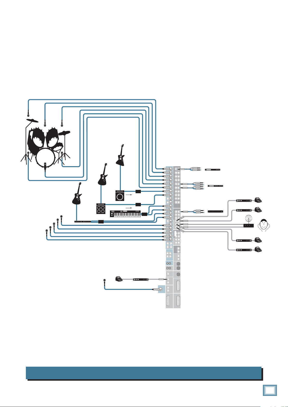
This drawing shows the exibility of the Onyx 4•Bus for creating different monitor
mixes. Auxes 1-4 provide separate monitor mixes for four floor wedges. Auxes 5-6
provide a stereo monitor mix for an in-ear monitor (IEM). The Aux Inserts can be
used for in-line graphic EQ for each monitor send. A listen wedge is connected to
the Monitor Out, allowing you to solo and listen to each monitor mix. The Talkback
Mic lets you talk to the talent through the monitors (Aux Sends).
Onyx 24•4 Stage Monitor Mix
Owner’s Manual
7
ONYX 4•Bus
Bass Guitar
Electric Guitar
Electric Guitar
Vocal Mics
Stereo Guitar Effects
Guitar Amp
Keyboard or Synth
DI Box
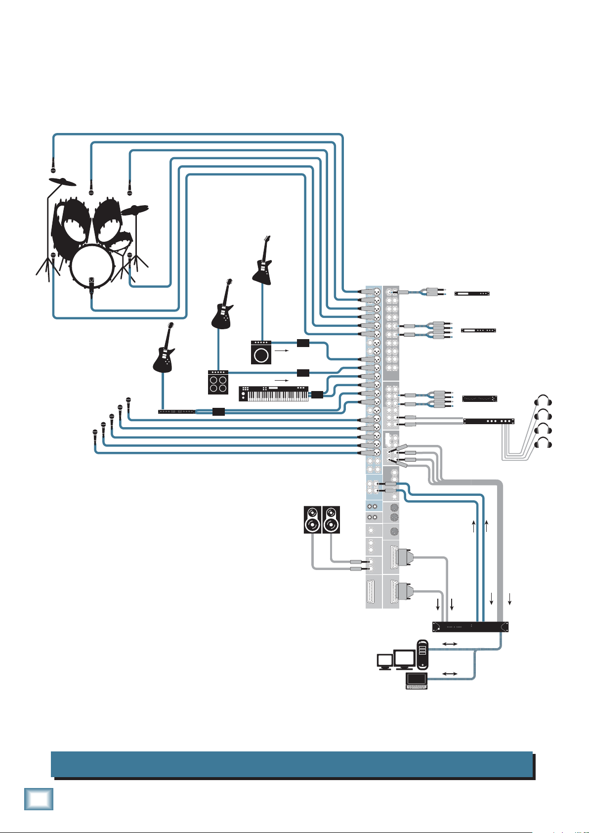
In this hookup diagram, the Direct Outs for channels 9-24
are connected to the analog audio interface for your DAW or
laptop for tracking. The drum microphones are subgrouped
to Groups 1-4 and routed to the analog audio interface for
recording.
A 2-track return is provided by the DAW (or laptop) to the
Stereo Returns on the Onyx 24•4 for playback of the master
mix.
Bass Amp
Line Out
Line Out
DI Box
DI Box
Studio Monitors
DI Box
Powered
for Studio
1
2
3
4
5
6
7
8
9
10
11
12
13
14
15
16
17
18
19
20
21 22
23 24
L
1
R
L
L
L
R
A
B
1
2
3
4
5
6
7
8
9
10
11
CHANNEL INPUTS
12
13
14
15
16
17
18
19
20
STEREO RETURNS
L
2
R
IN-TAPE-OUT
R
R
PHONES
OUT
MONTIOR
OUT
MATRIX
OUT
DIRECT OUT
1-8
1
11
2
12
3
13
4
14
5
15
6
16
CHANNEL INSERTS
7
17
8
18
19
9
10
20
1
4
2
5
3
6
AUX SEND INSERTS
1
4
2
5
AUX SEND
3
6
1
3
INSERTS
2
4
GROUP OUT
1
3
2
4
GROUP OUTS
L
MAIN
R
INSERTS
L
OUT
MAIN
R
OUT
MAIN
OUT
MONO
17-24
DIRECT OUT
9-16
DIRECT OUT
Mono Compressor
In
Out
In
Stereo Compressor
Out
In
Out
In
Out
In
Out
Headphone Distribution
Audio I/O for Workstation
To Desktop
or
Laptop Computer
Stereo EQ
Amp
Headphones
for Studio
Auxes 5-6 provide a stereo monitor mix for a headphone
distribution amplifier (Aux 5-6 Inserts are connected
to a stereo graphic EQ to provide equalization for the
headphone mixes).
Onyx 24•4 Computer Recording
8
ONYX 4•Bus
Vocal Mics
Hard Disk Recorder
Electric Guitar
Electric Guitar
Stereo Guitar Effects
Guitar Amp
DI Box
Mono EQ
Power Amp
Mono Mode
Bass Guitar
Bass Amp
Keyboard or Synth
Stereo Recorder
Line Out
Line Out
Mono EQ
Power Amp
Mono Mode
DI Box
DI Box
DI Box
Headphones
1
2
3
4
5
6
7
8
9
10
11
12
13
14
15
16
17
18
19
20
21 22
23 24
L
1
R
L
L
L
R
A
B
1
2
3
4
5
6
7
8
9
10
11
CHANNEL INPUTS
12
13
14
15
16
17
18
19
20
STEREO RETURNS
L
2
R
IN-TAPE-OUT
R
R
PHONES
OUT
MONTIOR
OUT
MATRIX
OUT
DIRECT OUT
1-8
1
11
2
12
3
13
4
14
5
15
6
16
CHANNEL INSERTS
7
17
8
18
19
9
10
20
1
4
2
5
3
6
AUX SEND INSERTS
1
4
2
5
AUX SEND
3
6
1
3
INSERTS
2
4
GROUP OUT
1
3
2
4
GROUP OUTS
L
MAIN
R
INSERTS
L
OUT
MAIN
R
OUT
MAIN
OUT
MONO
17-24
DIRECT OUT
9-16
DIRECT OUT
Mono Compressor
In
Out
In
Stereo Compressor
Out
In
Out
In
Out
In
Out
In
Out
Mono EQ
Power Amp
Mono Mode
Mono EQ
Stereo EQ
Power Amp
Mono Mode
Stage Monitors
Mono Power
Amplifier
Stereo In-Ear Monitor
System (IEM)
Assistive Listening
System
Power Amp
Mono Mode
Owner’s Manual
Power Amp
Mono Mode
Front Fill PA Speaker
SELECT
Balcony Seating Speaker
Nursery Zone Speaker
SELECT SELECT SELECT
Digital Multitrack
In a House of Worship application, the Onyx 4•Bus provides plenty of Aux Sends
for stage monitors, stereo in-ear monitoring, and assistive listening systems. The
MONO output is used to provide front-fill for the first few rows not covered by the
main PA speakers. A stereo graphic EQ is connected to the Main Inserts (the builtin compressor/limiter provides system limiting for the Main Mix). Aux 6 is used
as a subwoofer feed (a low-pass filter is built in to either the power amplifier or
subwoofer). The Matrix A and B outputs provide additional custom mixes for the
balcony and the nursery.
Onyx 24•4 House of Worship
Owner’s Manual
Left PA Speaker
Right PA Speaker
Subwoofer
9
Onyx 4•Bus Features
+10
Mono Channel Strips
The Onyx 24•4 has 20 mono channel strips and two
stereo channels, and the Onyx 32•4 has 28 mono channel
strips and two stereo channels. Each mono channel has a
ONYX 4•Bus
mic and line input connector and an insert jack for connecting an external signal processor.
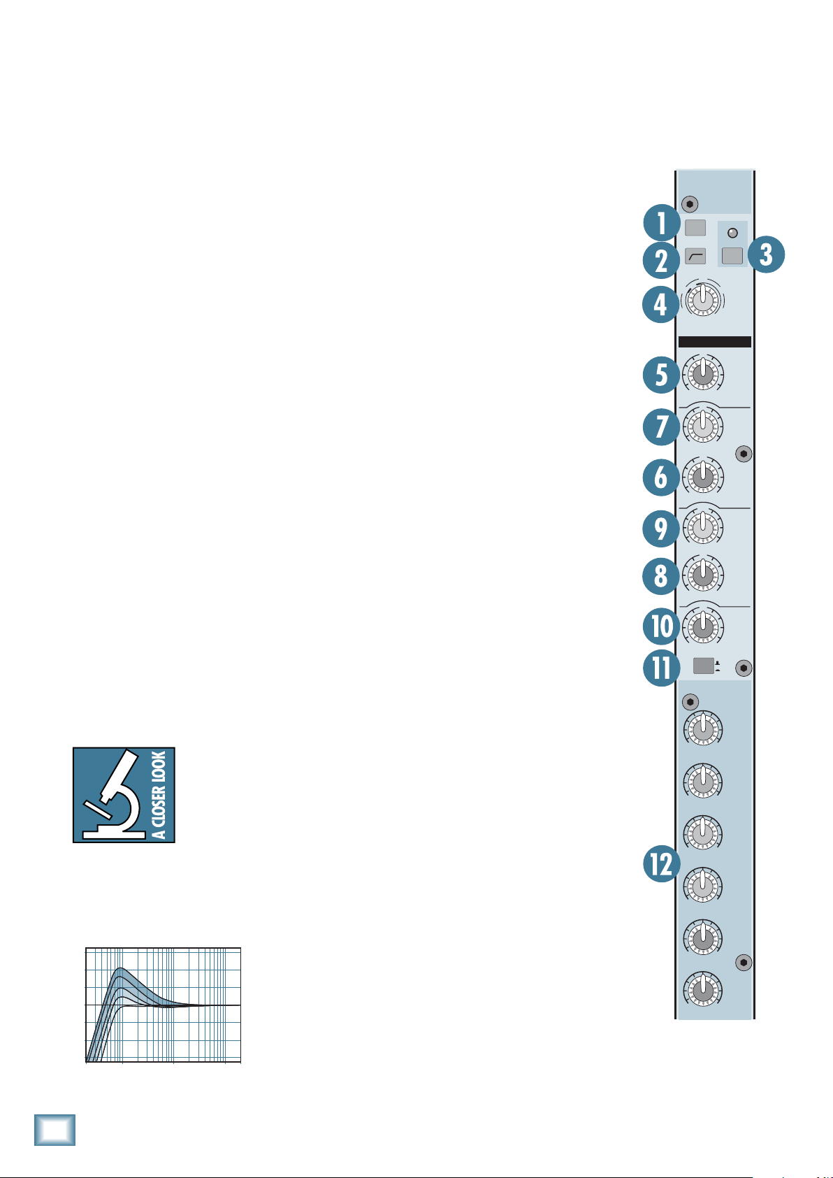
1. PAD Switch
In most cases, you will leave the PAD switch out. However, you may have a microphone that produces a higher
output signal than usual, which may require you to turn
the GAIN control way down.
the PAD switch to insert a 20 dB pad at the input to the
mic preamp, to prevent overloading the microphone preamp and provide better gain control.
2. Low-Cut Switch
The Low-Cut switch, often referred to as a high-pass
lter, cuts bass frequencies below 100 Hz at a rate of 18 dB
per octave.
We recommend that you use the Low-Cut switch on
every microphone application except kick drum, bass
guitar, bassy synth patches, or recordings of earth-
quakes. These aside, there isn’t much down there that
you want to hear, and filtering it out makes the low stuff
you do want much more crisp and tasty. Not only that,
but the Low-Cut switch can help reduce the possibility
If that is the case, push in
3. 48V Phantom Power Switch
Most professional condenser mi-
crophones require phantom power,
which is a low-current DC voltage
delivered to the microphone on
pins 2 and 3 of the XLR microphone
connector. Push in the 48V switch
if your microphone needs phantom
power. An LED lights just above the
switch to indicate that phantom
power is active on that channel.
Dynamic microphones, like
Shure’s SM57 and SM58, do not
require phantom power. However,
phantom power will not harm most
dynamic microphones should you
accidentally plug one in while the
phantom power is turned on. Be
careful with older ribbon microphones. Check the manual for your
microphone to find out for sure
whether or not phantom power can
damage it.
Note: Be sure the MAIN MIX fader
[72] is turned down when connecting microphones to the MIC Inputs,
especially when phantom power is
turned on, to prevent pops from getting through to the speakers.
20
U
-
PAD
U
20dB
GAIN
-
15
-
15
-
15
-
15
30
2k
400
EQ
U
U
U
U
+
40dB
+15
+15
+15
+15
8k 400
2k 1 00
48V 48V
40
60
HIGH
HIGH
LOW
OUT
IN
AUX
1
EQ
12kHz
FREQ
MID
FREQ
LOW
MID
80 Hz
of feedback in live situations and it helps to conserve
amplifier power.
Another way to use the Low-Cut switch
is in combination with the LOW EQ on
vocals during live performances.
Many
times, bass shelving EQ can really benefit voices. Trouble is, adding LOW EQ
also boosts stage rumble, mic handling
clunks, and breath pops. Low Cut removes all those problems so you can add LOW EQ without losing a woofer.
Here’s what the combination of LOW EQ and Low Cut
looks like in terms of frequency curves.
+15
4. GAIN Control
If you haven’t already, please read
“Set the Levels” on page 5.
The GAIN control adjusts the input
sensitivity of the mic and line inputs.
This allows the signal from the outside world to be adjusted to optimal
internal operating levels.
If the signal is plugged into the
XLR jack, there is 0 dB
(unity gain) with the knob turned
of gain
1
O O
MAX
2
O O
MAX
3
O O
MAX
4
O O
MAX
5
O O
MAX
all the way down, ramping up to 60
+5
0
–5
–10
–15
20Hz 100Hz 1kHz 10kHz 20kHz
Low Cut with Low EQ Boosted
dB of gain fully up (–20 dB to +40
dB with the PAD switch pushed in).
6
O O
MAX
When connected to the 1/4" jack, there is 20 dB of
attenuation all the way down, and 40 dB of gain fully up,
with a “U” (unity gain) mark at about 10:00.
10
ONYX 4•Bus
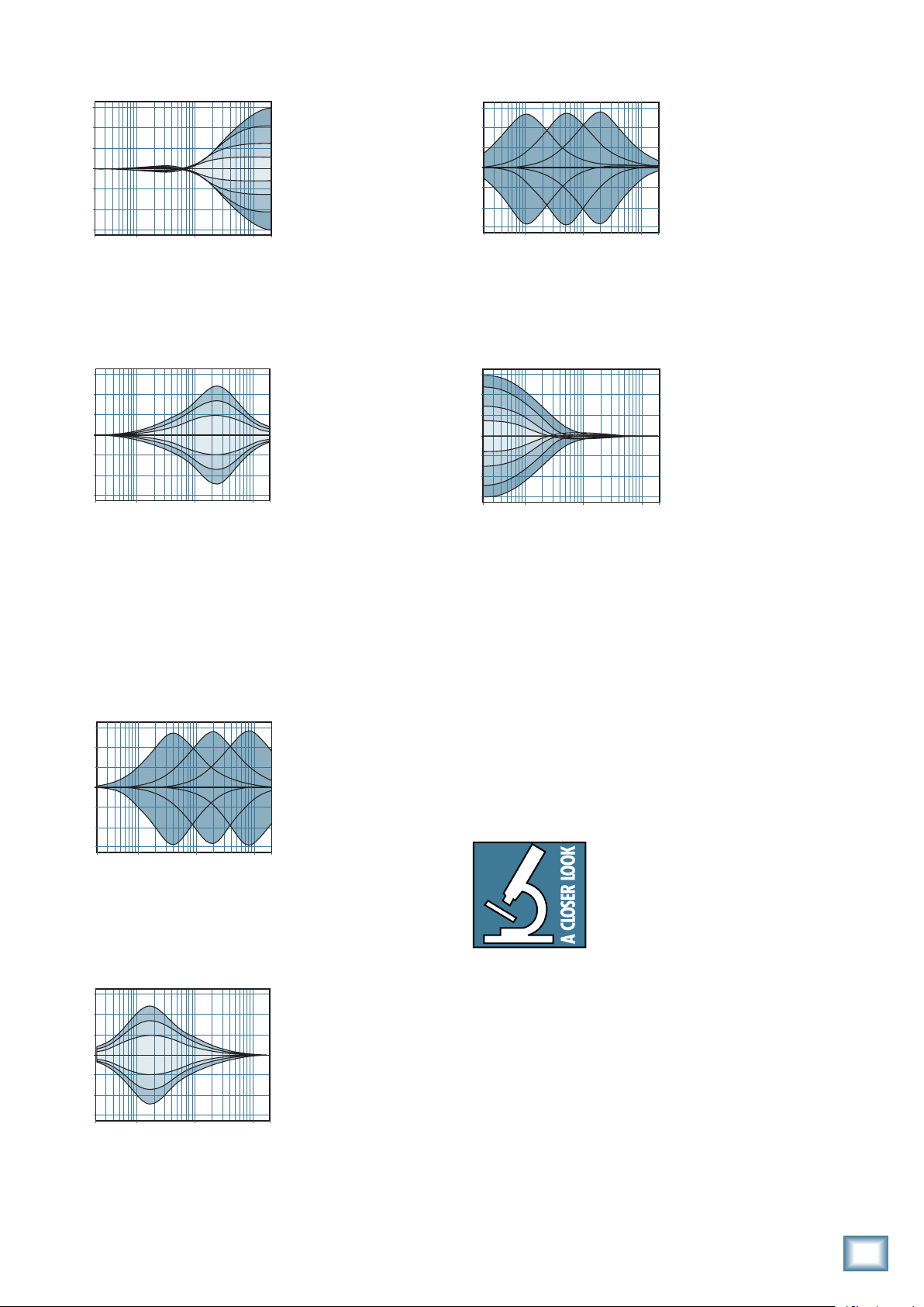
5. HIGH EQ
20Hz100
1k
10kHz20kHz
+10
20Hz 100Hz 1kHz 10kHz 20kHz
Owner’s Manual
9. LOW MID FREQ
+15
+10
+5
0
–5
–10
–15
20Hz100
High EQ
Hz
1k
Hz
10kHz20k
This control gives you
up to 15 dB boost or cut at
12 kHz, and is flat at the
center detent. Use it to
add sizzle to cymbals, and
an overall sense of transparency or edge to the
Hz
keyboards, vocals, guitar,
and bacon frying. Turn it
down a little to reduce sibilance, or to hide tape hiss.
6. HIGH MID EQ
+15
+10
+5
0
–5
–10
–15
20Hz100
Hz
1k
Hz
10kHz20k
High Mid EQ
the frequencies that dene any particular sound are
almost always found in this range. The HIGH MID EQ
range (400 Hz to 8 kHz) includes the female vocal range
as well as the fundamentals and harmonics for many
instruments.
Short for “midrange,”
this knob provides 15 dB
of boost or cut centered
at the frequency determined by its FREQ knob
(see HIGH MID FREQ
next). Midrange EQ is
Hz
often thought of as the
most dynamic because
+15
+10
+5
0
–5
–10
–15
Hz
Hz
Low Mid EQ Freq Sweep
This knob ranges from
100 Hz to 2 kHz and
determines the center
frequency for the LOW
MID EQ filter. This allows
you to zero in on the
precise narrow band of
frequencies you want to
have affected by the LOW
MID EQ.
10. LOW EQ
+15
+10
+5
0
–5
–10
–15
20
Hz
100
Hz
1k
Hz
10kHz20k
Low EQ
Note: Used in conjunction with the Low Cut switch,
you can boost the LOW EQ without injecting tons of
infrasonic debris into the mix.
This control gives you
up to 15 dB of boost or cut
at 80 Hz. The circuit is flat
(no boost or cut) at the
center detent position.
This frequency represents
the punch in bass drums,
Hz
bass guitar, fat synth
patches, and some really
serious male singers.
7. HIGH MID FREQ
+15
+10
+5
0
–5
–10
–15
High Mid EQ Freq Sweep
This knob ranges from
400 Hz to 8 kHz and
determines the center
frequency for the HIGH
MID EQ filter. This allows
you to zero in on the
precise narrow band of
frequencies you want
to have affected by the
HIGH MID EQ.
11. EQ IN/OUT Switch
This is a true hardware bypass of the Perkins EQ circuitry to insure that there is no coloration of the signal
if the EQ is not needed. When this button is out, the EQ
controls have no effect on the signal. You can use this
switch to make an A/B comparison between the EQ’d
signal and the signal without EQ.
We have completely redesigned the
EQ circuits in the Onyx Series of
mixers, based on the designs of Cal
Perkins, an industry-leader in audio
engineering for over three decades
8. LOW MID EQ
and long-time Mackie collaborator.
This “neo-classic” design provides the sweet musicality
+15
This is a second mid-
range EQ control that
+5
0
–5
–10
–15
20Hz100
Hz
Low Mid EQ
1k
Hz
provides 15 dB of boost
or cut centered at the
frequency determined by
its FREQ knob. It extends
down to 100 Hz, which
10kHz20k
Hz
includes the male vocal
range and the fundamen-
tals of some lower instruments (guitar, lower brass).
of the British EQ
boost and cut with optimum Q
(in other words, it gives you plenty of control and is
pleasing to the ear!).
The 4-band equalization has LOW shelving at 80 Hz,
LOW MID peaking, sweepable from 100 Hz to 2 kHz on
the mono channels, HIGH MID peaking, sweepable from
400 Hz to 8 kHz on the mono channels,
ing at 12 kHz. “Shelving” means that the circuitry boosts
or cuts all frequencies past the specied frequency. For
sound, while still maintaining 15 dB of
and minimum phase shift
and HIGH shelv-
example, rotating the LOW EQ knob 15 dB to the right
boosts bass frequencies below 80 Hz and
continuing on
Owner’s Manual
11
 Loading...