


STUDIO RECORDING PREAMP
with 192kHz FIREWIRE INTERFACE
OWNER’S MANUAL
Important Safety Instructions
instructions in the literature accompanying the appliance.
1. Read these instructions.
2. Keep these instructions.
3. Heed all warnings.
4. Follow all instructions.
5. Do not use this apparatus near water.
6. Clean only with dry cloth.
7. Do not block any ventilation openings. Install in accordance with the
ONYX 1200F
manufacturer’s instructions.
8. Do not install near any heat sources such as radiators, heat registers,
stoves, or other apparatus (including amplifiers) that produce heat.
9. Do not defeat the safety purpose of the polarized or grounding-type
plug. A polarized plug has two blades with one wider than the other.
A grounding-type plug has two blades and a third grounding prong.
The wide blade or the third prong are provided for your safety. If the
provided plug does not fit into your outlet, consult an electrician for
replacement of the obsolete outlet.
10.
Protect the power cord from being walked on or pinched particularly at
plugs, convenience receptacles, and the point where they exit from the
apparatus.
11.
Only use attachments/accessories specified by the manufacturer.
12.
Use only with a cart, stand, tripod, bracket, or
PORTABLE CART
table specified by the manufacturer, or sold with
the apparatus. When a cart is used, use caution
when moving the cart/apparatus combination to
avoid injury from tip-over.
13.
Unplug this apparatus during lightning storms or
when unused for long periods of time.
14.
Refer all servicing to qualified service personnel. Servicing is required
when the apparatus has been damaged in any way, such as powersupply cord or plug is damaged, liquid has been spilled or objects have
fallen into the apparatus, the apparatus has been exposed to rain or
moisture, does not operate normally, or has been dropped.
15.
This apparatus shall not be exposed to dripping or splashing, and no
object filled with liquids, such as vases, shall be placed on the apparatus.
16.
This apparatus has been designed with Class-I construction and must
be connected to a mains socket outlet with a protective earthing connection (the third grounding prong).
17.
This apparatus has been equipped with a single-pole, rocker-style AC
mains power switch. This switch is located on the front panel and
should remain readily accessible to the user.
CAUTION
RISK OF ELECTRIC SHOCK. DO NOT OPEN
CAUTION: TO REDUCE THE RISK OF ELECTRIC SHOCK DO NOT REMOVE COVER (OR BACK)
NO USER-SERVICEABLE PARTS INSIDE. REFER SERVICING TO QUALIFIED PERSONNEL
The lightning flash with arrowhead symbol within an equilateral triangle is
intended to alert the user to the presence of uninsulated "dangerous
voltage" within the product's enclosure, that may be of sufficient magnitude
to constitute a risk of electric shock to persons.
WARNING
18. NOTE: This equipment has been tested and found to comply with
the limits for a Class B digital device, pursuant to part 15 of the FCC
Rules. These limits are designed to provide reasonable protection
against harmful interference in a residential installation. This
equipment generates, uses, and can radiate radio frequency energy
and, if not installed and used in accordance with the instructions,
may cause harmful interference to radio communications. However,
there is no guarantee that interference will not occur in a particular
installation.
If this equipment does cause harmful interference to radio or
television reception, which can be determined by turning the
equipment off and on, the user is encouraged to try to correct the
interference by one or more of the following measures:
• Reorientorrelocatethereceivingantenna.
• Increasetheseparationbetweentheequipmentandthereceiver.
• Connecttheequipmentintoanoutletonacircuitdifferentfrom
that to which the receiver is connected.
• Consultthedealeroranexperiencedradio/TVtechnicianforhelp.
CAUTION: Changes or modifications to this device not expressly
approved by LOUD Technologies Inc. could void the user’s authority to
operate the equipment under FCC rules.
19. This apparatus does not exceed the Class A/Class B (whichever is
applicable)
set out in the radio interference regulations of the Canadian Department
limits for radio noise emissions from digital apparatus as
of Communications.
ATTENTION — Le présent appareil numérique n’émet pas de bruits
radioélectriques dépassant las limites applicables aux appareils numériques de
class A/de class B (selon le cas) prescrites dans le réglement sur le brouillage
radioélectrique édicté par les ministere des communications du Canada.
20.
Exposure to extremely high noise levels may cause permanent hearing
loss. Individuals vary considerably in susceptibility to noise-induced
hearing loss, but nearly everyone will lose some hearing if exposed to
sufficiently intense noise for a period of time. The U.S. Government’s
Occupational Safety and Health Administration (OSHA) has specified
the permissible noise level exposures shown in the following chart.
According to OSHA, any exposure in excess of these permissible limits
could result in some hearing loss. To ensure against potentially dangerous exposure to high sound pressure levels, it is recommended that all
persons exposed to equipment capable of producing high sound pressure levels use hearing protectors while the equipment is in operation.
Ear plugs or protectors in the ear canals or over the ears must be worn
when operating the equipment in order to prevent permanent hearing
loss if exposure is in excess of the limits set forth here.
Duration, per
day in hours
8 90 Duo in small club
6 92
4 95 Subway Train
3 97
2 100 Veryloudclassicalmusic
1.5 102
1 105 Fooyoung screaming at desTROYer about deadlines
0.5 110
0.25 or less 115 Loudest parts at a rock concert
Sound Level dBA,
Slow Response
Typical Example
WARNING — To reduce the risk of fire or electric shock, do not
expose this apparatus to rain or moisture.
The exclamation point within an equilateral triangle is intended to alert the
user of the presence of important operating and maintenance (servicing)
Correct Disposal of this product: This symbol indicates that this product should not be disposed of with your household waste, according to the WEEE Directive
(2002/96/EC) and your national law. This product should be handed over to an authorized collection site for recycling waste electrical and electronic equipment (EEE). Improper handling
of this type of waste could have a possible negative impact on the environment and human health due to potentially hazardous substances that are generally associated with EEE. At the
same time, your cooperation in the correct disposal of this product will contribute to the effective usage of natural resources. For more information about where you can drop off your waste
equipment for recycling, please contact your local city office, waste authority, or your household waste disposal service.
2
ONYX 1200F

Table of Contents
Introduction .................................................................................................................................5
Getting Started ........................................................................................................................... 7
Zero the Controls ....................................................................................................................................................................7
Connections ..............................................................................................................................................................................7
Set the Levels ...........................................................................................................................................................................7
Record to CD Using the DAW Mixer ..................................................................................................................................7
Record to CD Using the DSP Mixer ................................................................................................................................... 8
Standalone Mode .................................................................................................................................................................. 8
Hookup Diagrams ..................................................................................................................... 10
Onyx 1200F Features................................................................................................................. 14
Front Panel ..............................................................................................................................................................................14
1. Signal Level Indicators ..................................................................................................................................................14
2. 48V Phantom Power Switch ......................................................................................................................................14
3. LINE Switch......................................................................................................................................................................14
4. Channel GAIN ................................................................................................................................................................14
5. Instrument Input ...........................................................................................................................................................14
6. Instrument Switch ........................................................................................................................................................15
7. PHONES 1-4 Level ........................................................................................................................................................... 15
8. PHONES 1-4 Outputs .................................................................................................................................................... 15
9. CLOCK SOURCE Select and Indicators ....................................................................................................................15
10. METERING Select and Indicators ............................................................................................................................16
11. SAMPLE RATE Select and Indicators .......................................................................................................................16
12. FireWire Indicator .......................................................................................................................................................16
13. MIDI Indicators .............................................................................................................................................................16
14. TALK TO PHONES Level Control ..............................................................................................................................16
15. TALK TO PHONES On/Off Switch ..........................................................................................................................16
16. OUTPUTS 1-8 Level Control ......................................................................................................................................16
17. Output Level BYPASS ..................................................................................................................................................17
18. MONITOR Level Control ........................................................................................................................................... 17
19. MONITOR A/B Select Switch ..................................................................................................................................17
20. Power Switch ............................................................................................................................................................... 17
Owner’s Manual
Rear Panel ............................................................................................................................................................................... 17
21. MIC/Line Inputs ...........................................................................................................................................................17
22. INSERTS ..........................................................................................................................................................................17
23. TALKBACK MIC .............................................................................................................................................................18
Don’t forget to visit our website at www.mackie.com for more
information about this and other Mackie products.
Part No. SW0597 Rev. B 03/12
©2007-2012 LOUD Technologies Inc. All Rights Reserved.
Owner’s Manual
R
3

24. CONTROL RM MONITORS A/B .............................................................................................................................18
25. MIDI IN/OUT (1 and 2) ...............................................................................................................................................18
26. FIREWIRE ......................................................................................................................................................................18
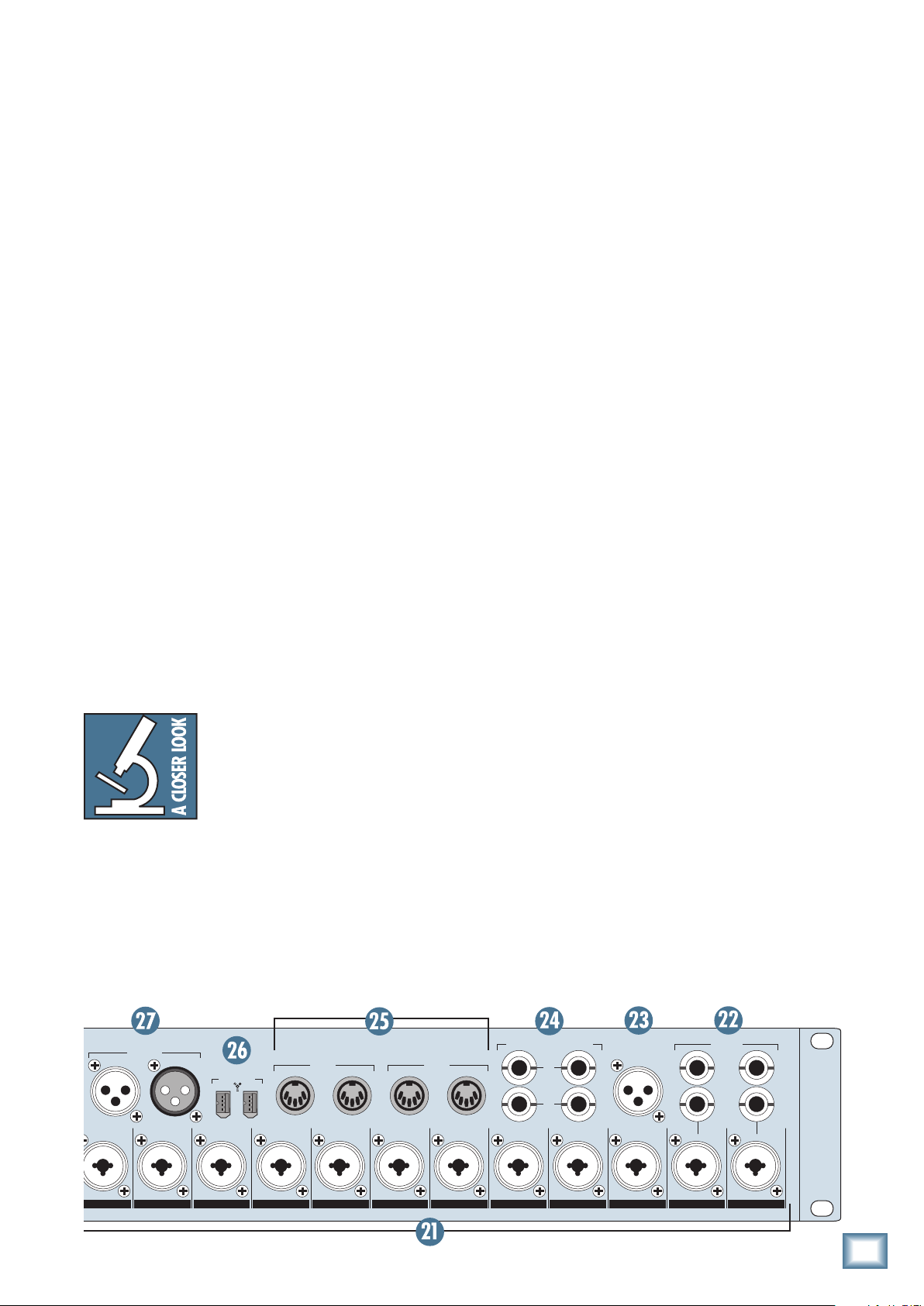
27. AES/EBU IN/OUT .......................................................................................................................................................19
28. S/PDIF IN/OUT ...........................................................................................................................................................19
29. ADAT IN/OUT (A/B) .................................................................................................................................................20
30. EXTERNAL WORD CLOCK IN/OUT.......................................................................................................................20
ONYX 1200F
31. 8 CHANNEL BALANCED LINE LEVEL OUTPUT ......................................................................................................21
32. MON A/B FOOTSWITCH .......................................................................................................................................... 21
33. TALKBACK FOOTSWITCH ..........................................................................................................................................21
34. AC Power Receptacle .................................................................................................................................................21
Onyx 1200F Console ..................................................................................................................21
Installing the Software ........................................................................................................................................................21
Computer Requirements ................................................................................................................................................. 21
A Note about Hard Drive Speed: ...................................................................................................................................21
Installing the Drivers and Onyx 1200F Console ....................................................................................................... 22
Macintosh OS X Audio MIDI Setup ..............................................................................................................................23
Installing Tracktion .......................................................................................................................................................... 24
Using the Onyx 1200F Console ......................................................................................................................................... 24
Settings ................................................................................................................................................................................ 25
Outputs ...............................................................................................................................................................................28
Standalone Mode .............................................................................................................................................................29
Appendix A: Service Information .........................................................................................30
Troubleshooting ................................................................................................................................................................... 30
Repair ....................................................................................................................................................................................... 31
Appendix B: Connections .......................................................................................................32
Appendix C: Technical Info ....................................................................................................34
Onyx 1200F Specifications .................................................................................................................................................. 34
Onyx 1200F Block Diagram ................................................................................................................................................. 36
Onyx 1200F Limited Warranty ..............................................................................................39
Please write your serial number here for future
reference (i.e., insurance claims, tech support,
return authorization, etc.)
Purchased at:
Date of purchase:
4
ONYX 1200F

Introduction
Onyx 1200F Input/Output Chart
Owner’s Manual
Thank you for choosing a Mackie Onyx 1200F professional audio interface for live or studio analog or digital
audio recording. The 1200F is equipped with twelve
of our Onyx Series precision-engineered studio-grade
microphone preamps, designed for the digital era and
offering the newest features and latest technologies for
live sound reinforcement and analog or digital studio
recording in a durable, road-worthy package. Its selection of analog and digital output options provides the
flexibility to connect in almost any application (including an HDR in standalone mode).
Mackie is renowned for the high-quality mic preamps
used in our mixers, and the Onyx mic pre’s are better
than ever, with specifications rivaling other stand-alone
boutique mic preamplifiers at twice the price.
Channels 1 and 2 have balanced send and return insert jacks for connecting to an external signal processor.
Channels 11 and 12 feature an unbalanced instrument
input jack and select switch, which lets you connect an
acoustic, electric, or bass guitar pickup directly to the
preamp, eliminating the need for an external direct box.
Channels 1-12 have Neutrik™ Combo input connectors, which allows you to use either a 1/4” TRS connector or an XLR connector. A 48V switch is provided for
each channel and applies phantom power to pins 2 and
3 of the channel’s XLR input connector.
Two pairs of balanced control room monitor outputs
are provided for connecting to powered monitors (or
power amplifier/monitor combination), and can be
sourced from the audio streams for any adjacent pair
of analog outputs, stereo headphone outputs, or the
S/PDIF or AES/EBU outputs.
Eight channels of analog balanced line outputs are
provided on a DB-25 connector. Two channels of digital
inputs and outputs are provided on two S/PDIF RCAtype connectors and two AES/EBU XLR connectors. Up to
30 input channels and 34 output channels of digital I/O
(at 44.1/48 kHz) are provided on the FireWire connectors (see chart below). There are two FireWire connec-
tors so the Onyx 1200F can be placed in a daisy-chain
FireWire connection. Two pairs of ADAT optical connectors are included, which provide up to 16 channels
of ADAT formatted digital I/O (16 channels at 44.1/48
kHz and 8 channels at 88.2/96 kHz). Two sets of MIDI
IN/OUT connectors are provided for sending and receiving MIDI information.
The Onyx 1200F is designed to be a transparent audio
interface for direct tracking to a DAW recording application on a PC or Mac. All 30 inputs are directly available
to the DAW application over the FireWire connection
(when operating at 44.1/48 kHz). The Console software
application allows you to route any input to any analog
or digital output on the 1200F, along with a pair of outputs from the DAW. This provides you with the choice of
direct monitoring, without going through the FireWire
connection and DAW software (zero latency), or monitoring through the DAW application.
You can provide a separate mix for each of the four
headphone outputs from any of the inputs and from two
of the outputs from the DAW. A talkback mic can be
routed to the four headphone outputs, operated from a
front panel button or a footswitch.
The Onyx 1200F Console Settings tab allows you to
choose the sample rate (44.1, 48, 88.2, 96, 176.4, or
192 kHz
) for the internal A/D and D/A converters. You
can select the clock source from an external clock connected to the external word clock (WordClk) input connector on the rear panel, from the S/PDIF or AES/EBU
input, from the ADAT 1 or ADAT 2 input, or from the
internal clock. You can turn the DSP Mixer on and off,
which allows you to operate the 1200F as a matrix mixer
with digital streams to a computer (DSP ON), or as a
standalone digital audio interface with digital streams
to and from a computer (DSP OFF). You can select
which inputs are routed to the Control Room outputs,
and whether the S/PDIF I/O is formatted for consumer
or professional status. You can adjust the buffer size
(latency), and select which I/O audio streams are active
on the FireWire connection.
Qty Inputs ASIO/Core Audio Stream
12 Mic/Line Inputs 1-12
8 Digital A Inputs 13-20
8 Digital B Inputs 21-28
2 S/PDIF/AES Inputs 29-30
30 Total Inputs
Note: The ASIO/Core Audio Stream assignments shown here apply when 44.1/48 kHz sample rate is selected.
At higher sample rates, the digital outputs are multiplexed using the S/MUX format, which reduces the number of
ASIO/Core Audio channels available for streaming. You can choose the inputs and outputs that are streamed to the DAW
at the higher sample rates in the Console’s Settings window.
Qty Outputs ASIO/Core Audio Stream
8 Analog Outputs 1-8
8 Digital A Outputs 9-16
8 Digital B Outputs 17-24
8 Headphone Outputs (4x2) 25-32
2 S/PDIF/AES Outputs 33-34
34 Total Outputs
Owner’s Manual
5

Onyx 1200F Features
HOW TO USE THIS MANUAL
• Premium30-inputx34-outputRecordingPreamp/
FireWire Audio Interface
• 12agshipOnyxmicpreampswithclass-leading
fidelity and dynamic range
• Mastering-gradeAKM®24-bit/192kHzA/DandD/A
converters
• DualFireWireportsfordaisychaininganddirect
ONYX 1200F
connection to Mac or PC
• 8balancedlineoutputsvia25-pinD-Subconnector
• 16x16ADATI/O@44.1/48kHz
(8x8@88.2/96kHz;disabled@176.4/192kHz)
• 4headphoneoutputswithvolumecontrolanddis-
crete stereo feeds
• PowerfulonboardDSPMatrixMixer:connectany
input to any output at near-zero latency
• Built-incontrolroomfunctions:A/BMonitor
Switching, Talkback, plus stereo and up to 7.1 surround output main volume control
• BalancedTRSsendandreturninsertjackson
Inputs 1 and 2
•
2x2 MIDI, plus Word Clock, AES/EBU and S/PDIF I/O
• Stand-alonemixerfunctionalityforeldandstudio
use without computer
We know that many of you can’t wait to get your
new preamp/FireWire interface hooked up, and you’re
probably not going to read the manual first (sigh!). So
the first section after this introduction is a Quick-Start
Guide called “Getting Started” to help you get the Onyx
1200F set up fast so you can start using it right away.
Right after that are the ever popular hook-up diagrams
that show typical setups for recording.
Then, when you have time, read the Features Description section. This describes every knob, button, and connection point on the Onyx 1200F, as well as the software
settings and controls.
Throughout this section you’ll find illustrations with
each feature numbered. If you want to know more about
a feature, simply locate it on the appropriate illustration, notice the number attached to it, and find that
number in the nearby paragraphs.
This icon marks information that is
critically important or unique to the
Onyx 1200F. For your own good, read
them and remember them. They will
be on the final test.
This icon leads you to in-depth
explanations of features and practical tips. While not mandatory, they
usually have some valuable nugget of
information.
•
Includes full version of Tracktion Music Production
Software for digital audio recording
A PLUG FOR THE CONNECTOR SECTION
AppendixBisasectiononconnectors:XLRconnectors, balanced connectors, unbalanced connectors, and
the insert connectors used on the Onyx 1200F.
More resources on our website at www.mackie.com.
THE GLOSSARY: A Haven of Non-Techiness for
the Neophyte
The “Glossary of Terms” is a fairly comprehensive
dictionary of pro-audio terms. If terms like “clipping,”
“noise floor,” or “unbalanced” leave you blank, refer to
this glossary for a quick explanation.
ARCANE MYSTERIES ILLUMINATED
“Arcane Mysteries” discusses some of the down ‘n’ dirty
practical realities of microphones, fixed installations,
grounding, and balanced versus unbalanced lines. It’s a
goldmine for the neophyte, and even the seasoned pro
might learn a thing or two.
6
ONYX 1200F

Getting Started
Owner’s Manual
READ THIS PAGE!!
Even if you’re one of those people
who never reads manuals, all we ask
is that you read this page now before
you begin using the Onyx 1200F.
You’ll be glad you did!
The Onyx 1200F can be used in standalone mode, or
connected to a computer with the FireWire connection.
Either way, you will want to install the Windows driv-
ers(aPCrequiresdriverstobeinstalled;aMachasthe
drivers built into the operating system) and the Onyx
1200F Console software on your computer first to get the
internal routing setup. Refer to page 21 for instructions
on installing the software.
Onceyou’veinstalledthesoftware,proceedasfollows:
Zero the Controls
1. Turn down the channel GAIN controls, and the
TALKTOPHONES,OUTPUTS1-8,MONITOR,and
PHONES level controls.
2. Set all push button switches to their “out” or “off”
positions.
5. Open the Onyx 1200F FireWire Console software
application.
6. Connect the S/PDIF output from the Onyx 1200F to
the S/PDIF input on a CD recorder or other S/PDIFcompatible recorder.
Set the Levels
To set the channel GAIN controls (on channels 1-12),
it’s not even necessary to hear what you’re doing at the
outputs of the preamplifier. The following steps must be
performed one channel at a time.
1. Play something into the selected input. This could
be an instrument, a singing or speaking voice, or
a line input such as a CD player or tape recorder
output. Be sure that the volume of the input source
is the same as it would be during normal use. If it
isn’t, you might have to readjust these levels later.
2. Adjust the channel’s GAIN control so that the
“–20” and “–10” LEDs light frequently or continuously, and the “OL” LED doesn’t light at all (or only
flashes occasionally).
3. Repeat for each channel.
3. Turn the POWER switch off.
Connections
This tutorial demonstrates how to mixdown up to
twelve input channels to a 2-track S/PDIF output, using
either the DSP mixer in the Onyx 1200F or your DAW
mixer, which can then be routed to a CD recorder
1. Plug a microphone into channel 1’s MIC input. You
can plug additional microphones or instruments
into channels 2-12.
2.
Connect the FireWire connector from the Onyx
to the FireWire connector on your computer.
1200F
Note: The Onyx 1200F is equipped with two 6-pin
FireWire connectors and comes with a 6-pin to
6-pin FireWire cable. If your computer has a 4-pin
FireWire connector, use the supplied 6-pin to 4-pin
FireWire adapter that came with your 1200F.
3. Plug in the detachable linecord, connect it to an
AC outlet, and turn on the Onyx 1200F’s POWER
switch.
4. If the microphone is a dynamic microphone, leave
the 48V switch out. If it’s a condenser microphone,
push in the 48V phantom power button to turn on
the phantom power for that channel.
:
Record to CD Using the DAW Mixer
This method routes the input signals directly to the
DAW via the FireWire connection, where each audio input signal is recorded on a separate track. Then you can
mixdown the tracks to two tracks that are routed back
to the Onyx 1200F and output on the S/PDIF output,
which is then routed to the CD recorder.
Select the Onyx 1200F as the sound device in your
1.
DAW application. Each DAW application has its own
method of doing this, so refer to your DAW application’s manual if you are not sure. In Tracktion, this
is done in “Audio Devices” under the “Settings” tab.
2. Assign the input signals from the 1200F to the tracks
in your DAW (if this isn’t done automatically). In
Tracktion, right-click on one of the Onyx 1200F
Audio Input icons and select “assign all inputs to
consecutive tracks” in the pop-up menu.
3. You should now see the signals from the Onyx 1200F
appearing on the meters in your DAW (make sure
each track is armed and ready to record). Start recording
clarity.
Note: The signals appearing at the inputs to the
DAW are not affected by the settings in the 1200F
and hear the Onyx 1200F in stunning crystal
Owner’s Manual
7

Console Output tabs. Each input on the Onyx 1200F
appears at its corresponding input in the DAW (see
Figure on the next page).
4. Now you can play back the recorded tracks and mix
them down to 2-track, which is routed back to the
Onyx 1200F S/PDIF outputs (and the CD recorder)
on DAW outputs 33 and 34.
Overdubbing
ONYX 1200F
Standalone Mode
1. Now you can use the Onyx 1200F in Standalone
mode by closing the 1200F Console and disconnecting the FireWire connection from your computer.
It retains the settings you made with the Console
Control Panel and you can take your Onyx 1200F on
location to make a stereo recording with your CD
recorder or other recording device connected to the
S/PDIF output.
You can expand on this method and overdub addition-
al tracks before mixing down to two tracks.
1. After you have recorded your initial tracks, you can
play them back from the DAW and monitor them on
one of the headphone outputs or the Control Room
outputs while recording additional instruments or
voices to the DAW.
2. When you have recorded all the tracks that you
want, mix them down to two tracks and route back
to the Onyx 1200F S/PDIF outputs (on DAW outputs
33 and 34) for recording to the CD recorder.
Record to CD Using the DSP Mixer
This method records directly to the CD recorder from
the S/PDIF output on the Onyx 1200F, without routing
the signals to the DAW.
Set the Console Control Panel
1. Select the “Settings” tab in the Console control
panel. Select 44.1 kHz sample rate, INT (internal)
clock source, and DSP Mixer On.
2. Select the “Headphones” button at the bottom of
the Console screen. Select the “Headphones 1”
tab at the top of the screen. Make sure the MUTE
buttons for Inputs 1-12 and the Master fader are
deselected and the faders are all the way up (0 dB).
Adjust the Pan controls to your preference. Use this
screen to setup your Headphone mix for monitoring.
3. Select the “Digital Outputs A” button at the bottom
of the Console screen and select “SPDIF/AES” at
the top of the screen (this is for the S/PDIF outputs). Set it the same way you did for Headphones
1 in step 2 above. This will give you the same mix in
your headphones that you are recording to CD.
4. Connect a pair of headphones to the Phones 1
output. Slowly turn up the Phones Level control
while music is playing and adjust for a comfortable
listening level.
5. Start recording and play your heart out.
In standalone mode, you can still use the front
Other Nuggets of Wisdom
• Youcanconnecttheanalogoutputsfromany
• AlwaysturntheOnyx1200Foffbeforemakingor
• Whenyoushutdownyourequipment,turnoffthe
• Neverlistentoloudmusicforprolongedperiods.
• Savetheshippingbox!Youmayneeditsomeday,
the “Hookup” section that shows you some typical ways
that you might use the Onyx 1200F in real applications.
After that, you can take the grand tour of the Onyx
1200F, with descriptions of every knob, button, input,
and output. We’ll also take a look at the Console software application in more detail. We encourage you to
take the time to read all of the feature descriptions, but
at least you know it’s there if you have any questions.
You can set up the Onyx 1200F as a
standalone rackmount mixer by adjusting the faders and pan controls for
all the inputs in the “Analog Outputs
1/2” tab in the Console Control Panel
and using the Control Room Monitor
outputs as the stereo output (the Control Room
Monitor Outputs mirror the analog outputs 1/2).
When you disconnect the FireWire connection between the 1200F and the computer, the settings are
retained. When you turn off the 1200F, the settings
are saved to the flash memory in the 1200F and
recalled the next time you turn it on.
panel gain knobs to control the relative volume for
each channel.
line-level source to the line inputs on the Onyx
1200F and use its high-quality analog-to-digital
converters to get your analog signals to your digital
recorder(s).
changing connections.
amplifiers first. When powering up, turn on the
amplifiers last.
Please see the Safety Instructions on page 2 for
information on hearing protection.
and you don’t want to have to pay for another one.
That’s it for the “Getting Started” section. Next comes
8
ONYX 1200F
Owner’s Manual
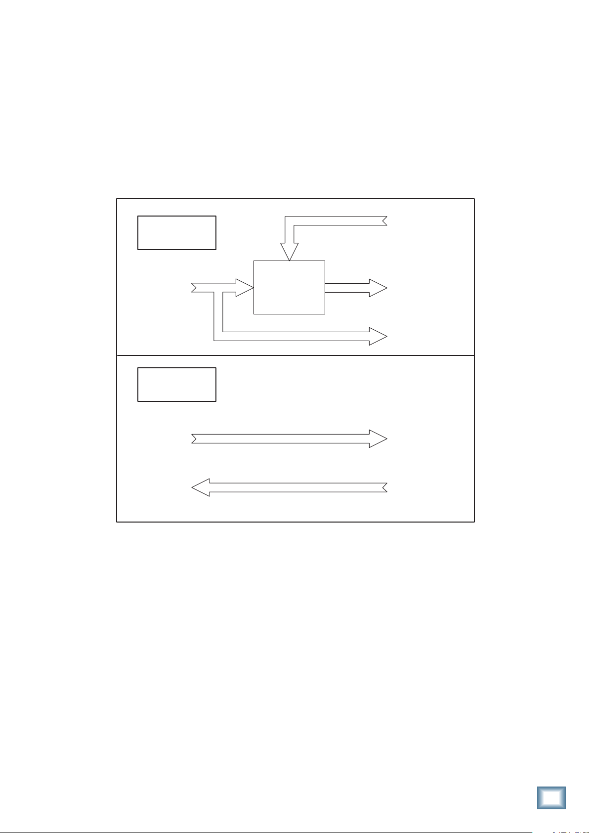
Onyx 1200F
DSP Mixer ON
Onyx 1200F
Inputs
Onyx 1200F
DSP Mixer OFF
Onyx 1200F
Inputs
Onyx 1200F
Audio Outputs
34
30
DSP Matrix
Mixer
30
30
34
34
FireWire
from DAW
Onyx 1200F
Audio Outputs
FireWire
to DAW
FireWire
to DAW
FireWire
from DAW
Onyx 1200F Signal Flow with DSP Mixer ON and OFF
Owner’s Manual
9
Hookup
Mackie Control
Mackie Control
Diagrams
ONYX 1200F
8 Microphones
to each
Onyx 800R
Onyx 800R
Onyx 800R
8 Inputs
8 Inputs
Headphones
for Talent
(from front panel)
WORD CLOCK
IN
~100-240 VAC
50-60Hz 45W
EXTERNAL
OUT
8 CHANNEL BALANCED
LINE LEVEL OUTPUT
ADAT
IN OUT
1
S/PDIF
IN
2
FOOTSWITCH
MON
A/B
TALK
BACK
C4 Pro
MACKIE CONTROL C4 PRO
FUNCTION MODIFIERSASSIGNMENT
1/3
2/2
MARKER
LOCK
3/1
SPOT ERASE
SPLIT
CHAN STRIP
TRACKSHIFT
OPTION
/ALT
FUNCTION
CONTROL
Universal Pro
MINUTES
HOURS
SECONDS
FRAMES
REC REC REC REC REC REC REC
dB
dB
dB
+
+
+
+
10
10
10
5
5
5
U
U
U
5
5
5
0
0
0
0
10
10
10
20
20
20
30
30
30
40
40
40
50
50
50
60
60
60
–
–
–
–
SMPTE
RUDE
SOLO
BEATS
ASSIGNMENT TICKSSUB DIVISIONBEATSBARS
87654321
VPOT ASSIGN
DISPLAY
NAME
SMPTE
TRACK
SEND
VALUE
BEATS
FUNCTION SELECT
PAN/
IN
PLUG
-
SURROUND
F1 F2 F3 F4 F5 F6 F7 F8
EQ INSTRUMENT
FADER BANKS
GLOBAL VIEW
BANK
MIDI
INPUTSAUDIO
AUDIO
AUXBUSSESOUTPUTS USER
TRACKS
TRACKS
INSTRUMENT
CHANNEL
MODIFIERS AUTOMATION UTILITIES
GLOBAL
FLIP
VIEW
SAVE
SHIFTOPTION READ/OFF
TRIM
UNDO
WRITE
MASTER
dB
dB
dB
dB
dB
+
+
+
10
10
10
10
10
CANCEL
ENTER
CONTROL
TOUCH
LATCH
ALT
/
GROUP
5
5
5
5
5
U
U
U
U
U
5
5
5
5
5
MARKER NUDGE
CYCLEDROP REPLACE CLICK
0
10
20
30
40
50
60
–
SOLO
0
0
10
10
10
10
FAST FWD PLAYSTOP RECORD
REWIND
20
20
20
20
30
30
30
30
FAST FWDPLAYSTOP RECORD
REWIND
40
40
40
40
50
50
50
50
60
60
60
60
–
–
SCRUB
ZOOM
Po wered
Studio Monitors B
Po wered
Studio Monitors A
MACKIE CONTROL UNIVERSAL PRO
87654321
REC
SIGNAL SIGNAL SIGNAL SIGNAL SIGNAL SIGNAL SIGNAL SIGNAL
dB
+
10
5
U
5
0
10
20
30
40
50
60
–
SLOT UP
PARAMETER
BANK
SINGLE
TRACK L
TRACK R
SLOT DOWN
Stereo Digital Reverb
AES/EBU
OUT IN
OUT
12 11 10 98765432 1
M
M
I
I
C
C
X
X
Y
Y
Y
P
P
R
R
N
N
O
N
E
E
O
O
X
FIREWIRE
M
I
C
MIDI 1
IN
M
I
C
X
Y
P
P
R
R
N
E
E
O
IN
OUT
M
M
I
I
C
C
X
X
Y
Y
P
P
R
R
N
N
E
O
O
CONTROL RM MONITORS
L21R
MIDI 2
OUT
M
M
I
I
C
C
X
X
Y
Y
P
R
N
N
E
E
O
O
TALKBACK
MIC
(48V)
A
B
M
M
I
C
X
P
R
E
X
Y
Y
P
R
N
N
E
O
O
M
I
I
C
C
X
Y
P
R
N
E
O
Mic 1
Compressor/Limiter
Talkback
Mic
INSERTS
(BALANCED)
SEND
RETURN
M
I
C
X
Y
P
P
R
R
N
E
E
O
Handheld
Switch
for
Talkback
Mics
External FireWire
Hard Drive
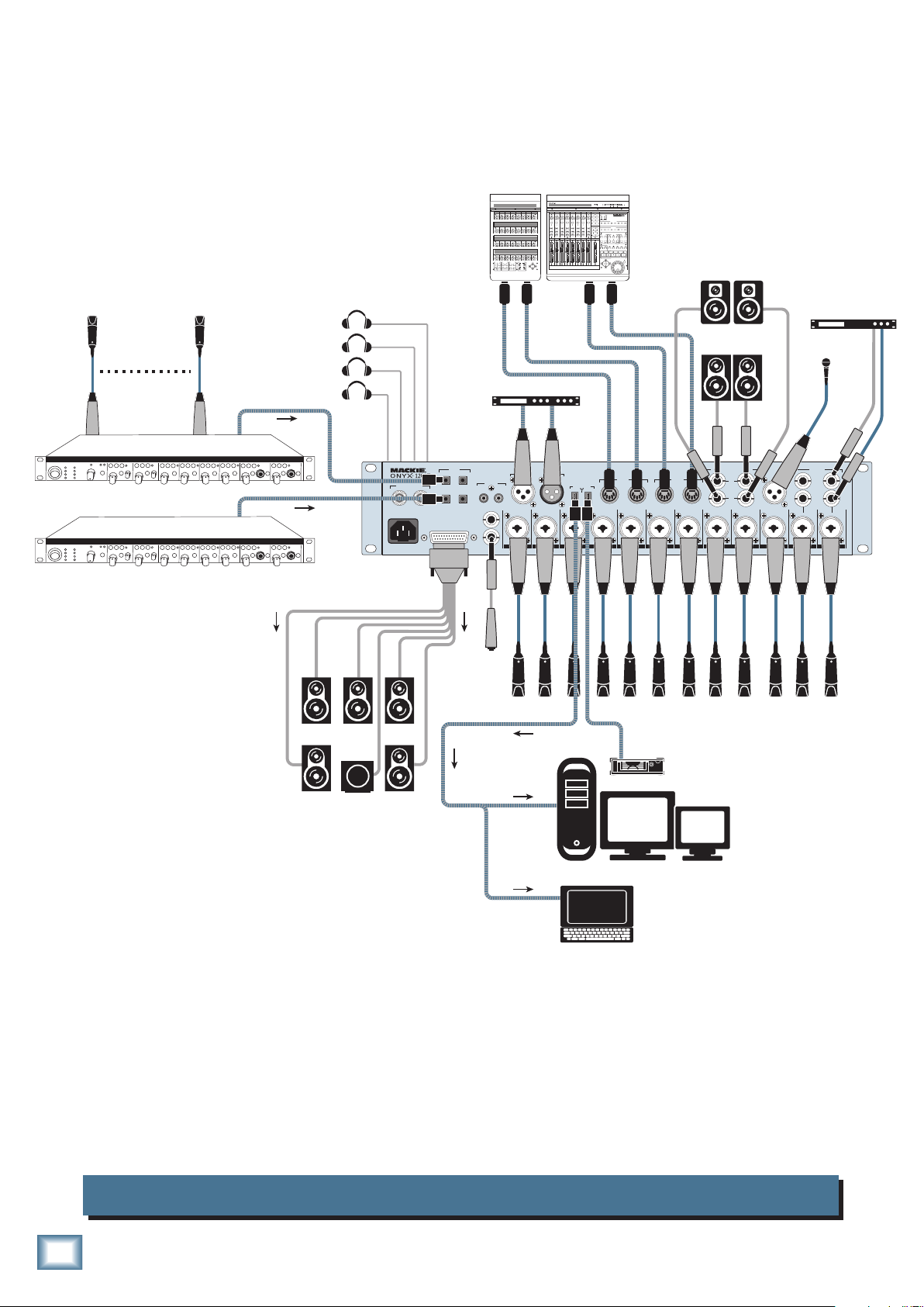
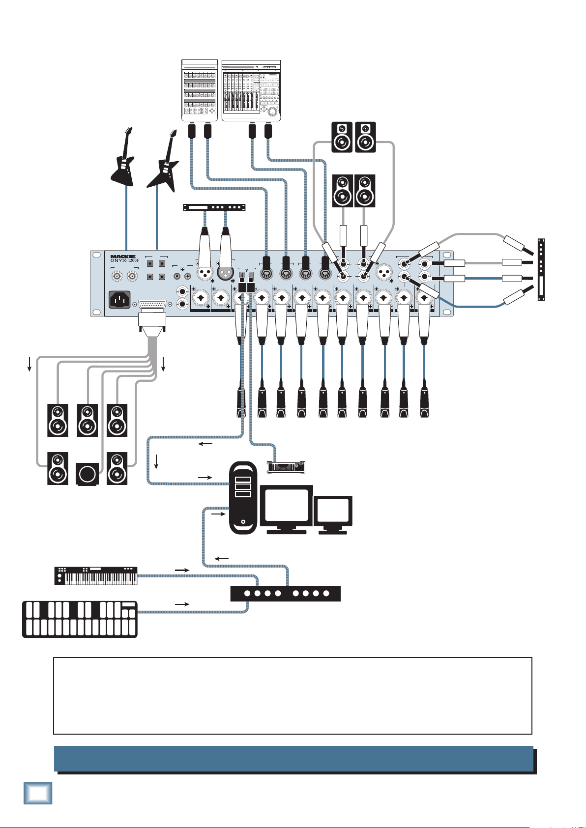
The FireWire connector on the Onyx 1200F can
be connected directly to a FireWire equipped
To Desktop
or
Laptop Computer
computer running a DAW application (Digital
Audio Workstation). In this example, there
are twelve microphones connected to the Onyx
1200F and 8 mics connected to each of the Onyx
800R microphone preamps feeding the ADAT inputs on the Onyx 1200F, for a total of 28 microphone feeds to the DAW.
Two different sets of studio monitor speakers are connected for control room monitoring. In addition,
five studio monitors and a subwoofer are connected to the line-level outputs for surround sound monitoring.
A stereo digital reverb is connected to the AES/EBU IN/OUT to add reverb to the vocals, and a compressor/
limiter
is connected to the channel 1 Insert Send/Return.
The four headphone outputs on the front of the 1200F are used for the musician’s monitors. Each headphone output is getting a separate, unique headphone mix from the DAW stereo aux sends. A Mackie
Control Universal and C4 are connected via the MIDI IN/OUTs, which controls the Tracktion software
installed on the computer. An external FireWire hard drive is connected to the second FireWire connection on the Onyx 1200F to serve as a dedicated memory storage device for the audio files.
10
Onyx 1200F Multitrack Recording with a DAW (Tracking)
ONYX 1200F
Owner’s Manual
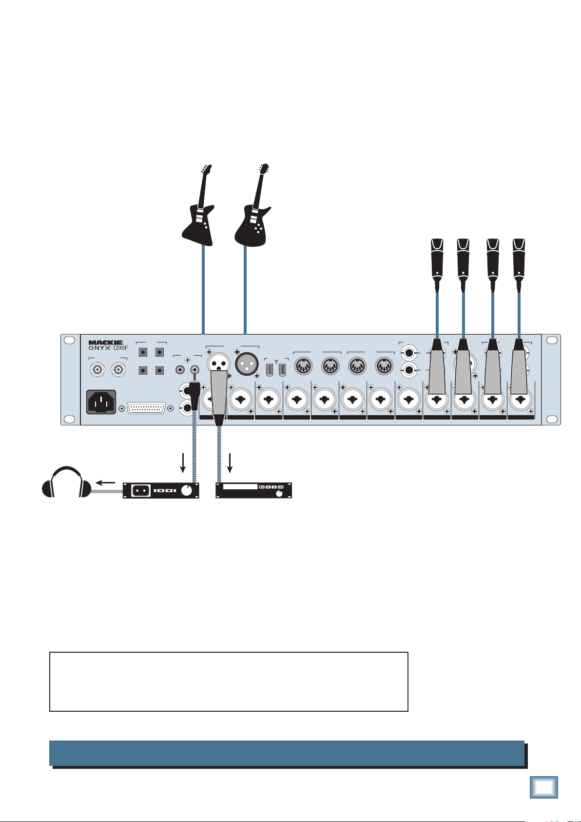
(to Instrument Input 11
EXTERNAL
WORD CLOCK
IN
~100-240 VAC
50-60Hz 45W
Headphones
For Engineer
(To Monitor Recording)
Bass Guitar
on Front Panel)
ADAT
IN OUT
OUT
1
2
8 CHANNEL BALANCED
LINE LEVEL OUTPUT
IN
FOOTSWITCH
MON
A/B
TALK
BACK
S/PDIF
Electric Guitar
(to Instrument Input 12
on Front Panel)
Mics
AES/EBU
OUT IN
OUT
12 11 10 9 8 7 6 5 4 3 2 1
M
I
C
X
X
Y
Y
P
R
N
N
E
O
O
FIREWIRE
M
M
I
I
C
C
X
Y
P
P
R
R
N
E
E
O
MIDI 1
IN
OUT
M
M
I
I
C
X
Y
N
O
C
X
Y
P
P
R
R
N
E
E
O
MIDI 2
IN
M
I
C
X
Y
P
R
N
E
O
O
OUT
M
I
C
X
Y
P
R
N
E
CONTROL RM MONITORS
L 2 1 R
A
B
M
I
C
X
Y
P
R
N
E
O
TALKBACK
MIC
(48V)
M
M
I
I
C
X
Y
N
O
C
X
Y
P
P
R
R
N
E
E
O
Y
N
O
Mics
M
I
C
X
P
R
INSERTS
(BALANCED)
SEND
RETURN
E
M
I
C
X
Y
P
R
N
E
O
Stereo DAT Recorder
(with S/PDIF Input)
Backup CD Recorder
(with AES/EBU Input)
This illustrates a simple direct to 2-track recording setup. You can
configure the Onyx 1200F beforehand with the desired sampling rate,
with the inputs routed to the S/PDIF output. The AES/EBU output on the
Onyx 1200F carries the same signal as the S/PDIF out, and is connected
to the AES/EBU input on a stereo CD recorder for backup
.
Onyx 1200F 2-Track Recording
Owner’s Manual
11
Bass and Electric Guitars
(to Instrument Inputs 11 and 12
on Front Panel)
Mackie Control
C4 Pro
MACKIE CONTROL C4 PRO
87654321
SLOT UP
PARAMETER
FUNCTION MODIFIERSASSIGNMENT
BANK
1/3
2/2
MARKER
TRACKSHIFT
LOCK
OPTION
3/1
SINGLE
TRACK L
TRACK R
/ALT
FUNCTION
CONTROL
SPOT ERASE
SPLIT
CHAN STRIP
SLOT DOWN
Mackie Control
Universal Pro
MACKIE CONTROL UNIVERSAL PRO
87654321
REC
REC REC REC REC REC REC REC
SIGNAL SIGNAL SIGNAL SIGNAL SIGNAL SIGNAL SIGNAL SIGNAL
dB
dB
dB
dB
dB
dB
dB
dB
+
+
+
+
+
+
+
+
10
10
10
10
10
10
10
10
5
5
5
5
5
5
5
5
U
U
U
U
U
U
U
U
5
5
5
5
5
5
5
5
0
0
0
0
0
0
0
0
10
10
10
10
10
10
10
10
20
20
20
20
20
20
20
20
30
30
30
30
30
30
30
30
40
40
40
40
40
40
40
40
50
50
50
50
50
50
50
50
60
60
60
60
60
60
60
60
–
–
–
–
–
–
–
–
ASSIGNMENT TICKSSUB DIVISIONBEATSBARS
VPOT ASSIGN
TRACK
PAN/
SURROUND
EQ INSTRUMENT
FADER BANKS
BANK
CHANNEL
FLIP
MASTER
SEND
PLUG
-
IN
GLOBAL
VIEW
dB
10
5
U
5
10
20
30
40
50
60
MINUTES
HOURS
SMPTE
BEATS
DISPLAY
SMPTE
NAME
BEATS
VALUE
FUNCTION SELECT
F1 F2 F3 F4 F5 F6 F7 F8
GLOBAL VIEW
AUDIO
MIDI
INPUTS AUDIO
TRACKS
TRACKS
INSTRUMENT
MODIFIERS AUTOMATION UTILITIES
SHIFTOPTION READ/OFF
WRITE
CONTROL
TOUCH
LATCH
/ALT
MARKER NUDGE
CYCLEDROP REPLACE CLICK
FAST FWD PLAYSTOP RECORD
REWIND
FAST FWDPLAYSTOP RECORD
REWIND
ZOOM
SECONDS
AUX BUSSES OUTPUTSUSER
FRAMES
RUDE
SOLO
SAVE
TRIM
UNDO
CANCEL
ENTER
GROUP
SOLO
SCRUB
Po wered
Studio Monitors B
ONYX 1200F
EXTERNAL
WORD CLOCK
IN
~100-240 VAC
50-60Hz 45W
OUT
ADAT
IN OUT
1
2
8 CHANNEL BALANCED
LINE LEVEL OUTPUT
Stereo Digital Reverb
AES/EBU
OUT IN
S/PDIF
OUT
IN
FOOTSWITCH
MON
A/B
TALK
BACK
12 11 10 987654321
M
I
C
X
Y
P
R
N
E
O
Po wered
Studio Monitors A
Out
FIREWIRE
CONTROL RM MONITORS
MIDI 1
IN
IN
OUT
MIDI 2
OUT
L21R
TALKBACK
A
B
M
M
I
C
X
Y
P
R
N
E
O
M
I
I
C
C
X
X
Y
Y
P
P
R
R
N
N
E
E
O
O
M
M
I
C
X
Y
P
R
N
E
O
M
M
M
I
I
C
C
X
X
Y
Y
P
P
R
R
N
N
E
E
O
O
I
I
C
C
X
X
Y
Y
P
P
R
R
N
N
E
E
O
O
O
INSERTS
(BALANCED)
MIC
(48V)
SEND
RETURN
M
M
M
I
C
X
Y
P
R
N
E
I
I
C
C
X
X
Y
Y
P
P
R
R
N
N
E
E
O
O
Out
In
Stereo Compressor
In
Mics
External FireWire
Hard Drive
To Desktop
Computer
USB
MIDI Keyboard Controller
MIDI
USB MIDI Interface
MIDI
MIDI Drum Controller
This illustrates the potential of the Onyx 1200F to do entire band recordings with a minimum of
physical gear or large recording spaces. Everything except the singers are “virtual!”
A USB MIDI
interface is used to connect an external MIDI keyboard controller and MIDI drum controller to
the computer running the DAW software, and a Mackie Control Universal connected to the MIDI
I/O on the Onyx 1200F to control the DAW
. The DAW is running an amp emulation plugin for the
guitars and virtual instrument plugins for the keyboard and drum controllers.
12
Onyx 1200F with DAW and External Controllers
ONYX 1200F

Owner’s Manual
Master
Master
Headphones
(from front panel)
EXTERNAL
WORD CLOCK
IN
~100-240 VAC
50-60Hz 45W
OUT
8 CHANNEL BALANCED
Video Deck 1
AES/EBU
S/PDIF
Converter
ADAT
IN OUT
1
2
LINE LEVEL OUTPUT
IN
FOOTSWITCH
MON
A/B
TALK
BACK
S/PDIF
Video Deck 2
AES/EBU
In/Out
AES/EBU
OUT IN
OUT
12 11 10 9 8 7 6 5 4 3 2 1
M
I
C
X
X
Y
Y
P
R
N
N
E
O
O
FIREWIRE
M
M
I
I
C
C
X
Y
P
P
R
R
N
E
E
O
MIDI 1
IN
OUT
M
M
I
I
C
X
Y
N
O
C
X
Y
P
P
R
R
N
E
E
O
MIDI 2
IN
M
I
C
X
Y
P
R
N
E
O
O
OUT
M
I
C
X
Y
P
R
N
E
CONTROL RM MONITORS
L 2 1 R
A
B
M
I
C
X
Y
P
R
N
E
O
TALKBACK
MIC
(48V)
M
M
I
I
C
X
Y
N
O
C
X
Y
P
P
R
R
N
E
E
O
External FireWire
Hard Drive
Video Deck Video Deck Video Deck
INSERTS
(BALANCED)
SEND
RETURN
M
M
I
I
C
X
Y
N
O
C
X
Y
P
P
R
R
N
E
E
O
To Desktop
or
Laptop Computer
This illustrates an audio/video application where several video decks are connected to the inputs on the Onyx 1200F, and use the Console control panel to route the audio to the two Master
Video decks from the S/PDIF (via a S/PDIF to AES/EBU converter) and AES/EBU digital audio
outputs from the 1200F. The AES/EBU digital audio outputs from the Master Video decks are
connected to the S/PDIF (again, through the converter) and AES/EBU inputs on the Onyx 1200F.
These can be individually selected in the Console Settings panel and routed to the DAW software
application on a laptop or desktop computer via the FireWire connection.
Onyx 1200F Audio/Video Application
Owner’s Manual
13

Onyx 1200F Features
OO
MAX
OO
MAX
OO
MAX
OO
1
PHONES
2 3 4
OO
MAX
O
CONTROL ROOM
OUTPUTS 1-8
176.4kHz
96kHz
88.2kHz 192kHz
MIDIINMIDI
OUT
RCE
ADAT-2 FWADAT-1
AES
S/PDIF
OUT-A
TALK TO
PHONES
ON
Front Panel
There are twelve mic/line inputs on the Onyx 1200F.
They all
Inputs
inserting an external signal processor into the signal
ONYX 1200F
path, and inputs 11 and 12 have an unbalanced 1/4"
share the same features with the exception that
1 and 2 have balanced send and return jacks for
input jack on the front panel for connecting unbalanced
high-impedance electric instruments directly to the
preamp without a direct box.
1. Signal Level Indicators
These LEDs indicate the channel’s signal level after
the GAIN control and the INSERT jack.
If you’ve followed the “Set the Levels” procedure on
page 6, the –20 and –10 LEDs should light frequently,
and the OL (Overload) LED should not light at all. If
the OL LED is blinking frequently, the signal is probably
distorted from overdriving the input. Either turn down
the GAIN control or turn down the signal at its source.
2. 48V Phantom Power Switch
Most professional condenser microphones require
phantom power, which is a low-current DC voltage
delivered to the microphone on pins 2 and 3 of the XLR
microphone connector. Push in the 48V button if your
microphone needs phantom power. An LED lights next
to the button to indicate that phantom power is active.
Dynamic microphones, like Shure’s SM57 and SM58,
do not require phantom power. However, phantom
power will not harm most dynamic microphones should
you accidentally plug one in while the phantom power is
turned on. Be careful with ribbon microphones. Check
the manual for your microphone to find out for sure
whether or not phantom power can damage it.
3. LINE Switch
Use this switch to select the proper gain for the Onyx
mic/line preamp. Normally, leave the LINE switch out,
since the gain control provides a wide range of control
over the input level.
However, if you have a particularly hot mic or linelevel signal, push in this switch to reduce the overall
gain by 20 dB.
4. Channel GAIN
The GAIN controls adjust the input sensitivity of the
mic and line inputs on channels 1-12. This allows the
signal from the outside world to be adjusted to optimal
internal operating levels.
With the LINE switch out, there is 0 dB of gain (unity
gain) with the knob turned all the way down, ramping
up to 60 dB of gain fully up.
With the LINE switch in, there is 20 dB of attenuation
all the way down, and 40 dB of gain fully up, with a “U”
(unitygain)markatabout10:00.
5. Instrument Input
Channels 11 and 12 each have a 1/4" TS connector that
accepts an unbalanced
from a high-impedance instrument like a guitar.
instrument-level input signal
14
OL
-10
-
20
-
40
48V
LINE
U
203040
U
60
-20dB
+40dB
GAIN
ONYX
MIC PRE
ONYX 1200F
STUDIO RECORDING PREAMP WITH 192kHz FIREWIRE I/O
LINE
OL
-10
-
20
-
40
48V
U
203040
60
U
+40dB
-20dB
GAIN
ONYX
MIC PRE
OL
-10
-
20
-
40
48V
U
203040
60
U
+40dB
-20dB
GAIN
ONYX
MIC PRE
48V
LINE
+40dB
MIC PRE
60
ONYX
OL
-10
-
20
-
40
LINE
U
203040
U
-20dB
GAIN
LINE
OL
-10
-
20
-
40
48V
U
203040
60
U
+40dB
-20dB
GAIN
ONYX
MIC PRE
48V
LINE
GAIN
+40dB
MIC PRE
60
ONYX
OL
-10
-
20
-
40
U
203040
U
-20dB
GAIN
OL
-10
-
20
-
40
U
203040
U
-20dB
GAIN
OL
21 3 4 5 6 7 8 9 10 11 12
-10
-
20
-
40
48V
LINE
U
203040
60
U
+40dB
-20dB
ONYX
MIC PRE
LINE
OL
-10
-
20
-
40
48V
U
203040
60
U
+40dB
-20dB
GAIN
ONYX
MIC PRE
LINE
OL
-10
-
20
-
40
48V
U
203040
60
U
+40dB
-20dB
GAIN
ONYX
MIC PRE
LINE
OL
-10
-
20
-
40
48V
U
203040
60
U
+40dB
-20dB
ONYX
MIC PRE
48V
LINE
GAIN
+40dB
MIC PRE
60
ONYX
OL
-10
-
20
-
40
48V
LINE
U
203040
U
-20dB
GAIN
CLOCK SOU
+40dB
ONYX
MIC PRE
60
METERING
SAMPLE RATE
UNBAL
UNBAL
INT WORD
IN-A OUT-D
44.1kHz
48kHz
11
12

6. Instrument Switch
Channels 11 and 12 have an extra button for switching
between the MIC/LINE and Instrument inputs. When
the button is out (MIC/LINE), the Neutrik Combo input
connector (XLR MIC input or the 1/4" LINE input)
is used, and the Instrument input [5] on the front
panel is disconnected. When the button is pushed in
(Instrument), the 1/4" Instrument input is used and
the Neutrik Combo inputs are disconnected. The input
stage of the Instrument inputs is specially designed for
the high-impedance pickups on electric guitars, basses,
acoustic guitar pickups, etc.
Plugging a guitar straight into a typical
line input can result in the loss of high
frequencies, causing an unnatural and
dull sound. Normally, you must use a
direct box between a guitar and the
input to a mixer or preamplifier, which serves to convert
the impedance of the guitar from high to low. The
Instrument inputs on channels 11 and 12 make the need
for a direct box unnecessary.
HOWEVER: The Instrument inputs are unbalanced, so
if you are running a long cord between the instrument
and the Onyx 1200F (say over 20 feet), it is best to use
a direct box with a balanced output to avoid picking up
noise over the length of the cord.
7. PHONES 1-4 Level
These four knobs adjust the signal level at the
PHONES Out jacks [8] on the front panel. They range
from off (∞) to maximum gain (MAX).
Having independent level control for each headphone
output means that in an overdub situation, for example,
the musician and the engineer can each adjust their
own headphone volume to taste.
When the DSP Mixer is turned on (in the Console’s
Owner’s Manual
Settings tab), each headphone output can have a separate and unique mix from any of the Onyx 1200F inputs
(including two audio streams from the DAW), using the
Console’s fader and pan controls.
When the DSP Mixer is turned off, only a pair of audio
streams from the DAW is fed to each headphone output.
You can create a stereo aux send in the DAW for each
headphone output, so each headphone output can still
have a separate and unique mix.
WARNING: The headphone amps are
designed to drive any standard headphones to a very loud level. We’re not
kidding! They can cause permanent
hearing damage. Even intermediate
levels may be painfully loud with some headphones.
BE CAREFUL! Always start with the PHONES level
turned all the way down before connecting headphones
tothePHONESjack.Keepitdownuntilyou’veputon
the headphones. Then turn it up slowly. Why? Always
remember:“Engineers who fry their ears, find themselves with short careers.”
9. CLOCK SOURCE Select and Indicators
When the Onyx 1200F is not connected to a computer
(Standalonemode),presstheCLOCKSOURCESelect
button to toggle the five clock source options. The five
LEDs indicate the clock source currently selected for
the Onyx 1200F. When the 1200F is connected to a computer via FireWire, the selection must be made in the
Onyx 1200F Console (on the PC or Mac).
Theveoptionsare:
INT: This is the default selection. The Onyx 1200F
runs on its own internal, extremely accurate, lowjitter clock. Select INT when using the 1200F as the
master clock in a system of digital devices, or if no
other clock source is available.
8. PHONES 1-4 Outputs
This is where you plug in your stereo headphones.
These are 1/4" TRS stereo jacks. Each PHONE jack has
its own individual level control [7].
OL
-10
-
20
-
40
48V
LINE
U
203040
U
-20dB
GAIN
12
+40dB
MIC PRE
CLOCK SOURCE
METERING
IN-A OUT-D OUT-A
SAMPLE RATE
11
UNBAL
60
ONYX
12
UNBAL
S/PDIF
ADAT-2 FWADAT-1INT WORD AES
MIDIINMIDI
OUT
176.4kHz44.1kHz 96kHz48kHz 88.2kHz 192kHz
1
OO
MAX
PHONES
2 3 4
OO
MAX
ON
OO
TALK TO
PHONES
OO
MAX
MAX
CONTROL ROOM
O
MAX
OUTPUTS 1-8
OO
MAX
A
B
WORD: The Onyx 1200F uses the clock signal that
appearsattheWORDCLOCKIN[30]connection
on the rear panel. Select WORD when you want the
1200F to be a slave in a system of digital devices.
AES/SPDIF: The Onyx 1200F uses the clock signal
embedded in the AES/EBU [27] or S/PDIF digital
input [28] signal.
ADAT-1: The Onyx 1200F uses the clock signal
that appears at the ADAT A digital optical
A/BBYPASS
OO
MONITOR
MAX
input [29] connection on the rear panel.
ADAT-2: The Onyx 1200F uses the clock signal
that appears at the ADAT B digital optical
ON
input [29] connection on the rear panel.
Tip: It’s always best to use the highest quality
clock as the master. Experimenting with different clock sources, and using your ears, is the
best way to determine which clock source to use.
Owner’s Manual
15

10. METERING Select and Indicators
12. FireWire Indicator
Press the METERING Select button to toggle the four
meter options. The three METERING LEDs, along with
the channel 12 meter, indicate the metering option currently selected for the Onyx 1200F.
Note: The METERING Select button works in both
Standalone Mode and when the Onyx 1200F is connected to a computer.
ONYX 1200F
Thefouroptionsare:
IN-A: With this setting, the front panel meters
display the levels for the 12 analog inputs, just after
the A/D converters. This allows you to visually confirm with each meter’s OL LED that the input signal
is not overloading that channel’s A/D converter.
OUT-D1: This setting displays the ADAT A digital
outputs on channels 1-8, and the 2-channel S/PDIF
and AES/EBU outputs on channels 9-10. Channel 11
is blank, and channel 12 has one LED lit to indicate
that ADAT A is being metered.
OUT-D2: This setting displays the ADAT B digital
outputs on channels 1-8, and the 2-channel S/PDIF
and AES/EBU outputs on channels 9-10. Channel
11 is blank, and channel 12 has two LEDs lit to
indicate that ADAT B is being metered.
OUT-A: This setting displays the analog outputs as
follows:
• Theeightanalogline-leveloutputson
channels 1-8.
• Themono-summedlevelsofthefouranalog
phones outputs on channels 9-12.
11. SAMPLE RATE Select and Indicators
Press the SAMPLE RATE Select button to toggle the
six sample rate options (44.1 kHz, 48 kHz, 88.2 kHz, 96
kHz, 176.4 kHz, 192 kHz). The six LEDs indicate the
sample rate currently selected for the Onyx 1200F. The
selection can also be made in the Onyx 1200F Console
(on the PC or Mac).
Note: The SAMPLE RATE Select button only works in
Standalone Mode. When the Onyx 1200F is connected to a
computer, make sure the sample rate setting in the Onyx
Console and the DAW application match.
I/O
LINE
OL
-10
-
20
-
40
48V
U
203040
60
U
+40dB
-20dB
GAIN
ONYX
MIC PRE
OL
-10
-
20
-
40
U
203040
U
-20dB
GAIN
OL
6 7 8 9 10 11 12
-10
-
20
-
40
48V
LINE
U
203040
60
U
+40dB
-20dB
GAIN
ONYX
MIC PRE
LINE
OL
-10
-
20
-
40
48V
U
203040
60
U
+40dB
-20dB
GAIN
ONYX
MIC PRE
LINE
OL
-10
-
20
-
40
48V
U
203040
60
U
+40dB
-20dB
GAIN
ONYX
MIC PRE
LINE
OL
-10
-
20
-
40
48V
+40dB
MIC PRE
60
ONYX
48V
LINE
U
203040
U
-20dB
GAIN
+40dB
MIC PRE
60
ONYX
OL
-10
-
20
-
40
48V
LINE
U
203040
U
+40dB
-20dB
GAIN
MIC PRE
This LED illuminates when a valid FireWire connec-
tion is made between the Onyx 1200F and a computer.
13. MIDI Indicators
The MIDI IN LED flashes whenever there is MIDI activity on the MIDI 1 and MIDI 2 IN connectors, and the
MIDI OUT LED flashes whenever there is MIDI activity
on the MIDI 1 and MIDI 2 OUT connectors.
14. TALK TO PHONES Level Control
The talkback feature allows the engineer to communicate with the talent through the PHONES [8] outputs,
usingamicrophoneconnectedtotheTALKBACKMIC
[23] connector on the rear panel.
Use this knob to control the level of the talkback
signal being routed to the PHONES outputs. You should
startwiththeTALKTOPHONESlevelcontrolturned
down, and then slowly turn it up until you get confirmation from whoever is listening to headphones that they
can hear you. Once you have set the level, you can leave
it there for the duration of the session (or the gig).
15. TALK TO PHONES On/Off Switch
This switch turns the talkback mic on and off. It is
a momentary switch, so you need to keep the button
pressed while you talk. When you let go of the button,
the talkback mic is off, and the indicating LED next to
the switch turns off. This feature is duplicated by the
TALKBACKFOOTSWITCH[33]ontherearpanel.
16. OUTPUTS 1-8 Level Control
Use this knob to adjust the signal level of the eight balanced line-level outputs on the DB-25 connector on the
rear panel. It ranges from off (∞) to unity gain (MAX).
Tip: This is handy when using the eight
line-level outputs for surround sound mixing because it gives you a single master volume control for all the surround outputs.
ON
OO
TALK TO
PHONES
OO
MAX
MAX
CONTROL ROOM
O
MAX
OUTPUTS 1-8
OO
MAX
A
B
OO
MONITOR
ON
CLOCK SOURCE
METERING
IN-A OUT-D OUT-A
SAMPLE RATE
11
UNBAL
60
ONYX
12
UNBAL
S/PDIF
ADAT-2 FWADAT-1INT WORD AES
MIDIINMIDI
OUT
176.4kHz44.1kHz 96kHz48kHz 88.2kHz 192kHz
1
OO
MAX
PHONES
2 3 4
OO
MAX
A/BBYPASS
MAX
16
ONYX 1200F
17. Output Level BYPASS
Owner’s Manual
Rear Panel
Turn the BYPASS switch on to remove the OUTPUT level
control from the signal path. This ensures that the signal
at the eight balanced line-level outputs is the same as the
DAW’s source channels. The indicating LED next to the
BYPASS switch lights when the bypass function is on. This
might be useful for sending a two-channel mix to a recorder, or for using these outputs (along with some line-level
inputs) as sends to a signal processor during mixdown.
18. MONITOR Level Control
Use this knob to adjust the signal level at the CONTROL RM MONITOR jacks on the rear panel. It adjusts
the signal for both the left and right Control Room Monitor outputs, ranging from off (∞) to unity gain (MAX).
Connect the CONTROL ROOM MONITOR outputs directly to the inputs of a pair of powered studio monitors.
No mixer required!
19. MONITOR A/B Select Switch
Use this button to select the CONTROL RM MONITOR A or CONTROL RM MONITOR B outputs [24]. The
LEDs next to the switch indicate whether Output A or
B is selected. The MONITOR Level Control [18] acts on
whichever Monitor output is selected.
Note: This function is duplicated with the MON A/B
FOOTSWITCH jack on the rear panel.
The rear panel is where you make all your analog and
digital audio connections to the Onyx 1200F (except for
the headphones and the high-impedance instrument
jacks on the front).
21. MIC/Line Inputs
These are Neutrik combo connectors, which accept
balanced microphone inputs from an XLR connector or
1/4"
balanced line-level inputs from a
TRS connector.
The microphone preamps feature our new Onyx design,
with higher fidelity and headroom rivaling any standalone mic preamp on the market today.
TheXLRinputsarewiredasfollows:
Pin 1 = Shield or ground
Pin 2 = Positive (+ or hot)
Pin 3 = Negative (– or cold)
The
1/4"
inputsarewiredasfollows:
Sleeve = Shield or ground
Tip = Positive (+ or hot)
Ring = Negative (– or cold)
22. INSERTS
These 1/4" TRS jacks provide a send and return point
for channels 1-2. Use the CHANNEL INSERT jacks to
connect serial effects devices such as compressors,
equalizers, de-essers, or filters to each individual channel.
When connecting two pairs of control
room monitors to the Onyx 1200F, it is
most effective to balance the sensitivity of the monitors so that they are
the same loudness when switching
The INSERT points are after the GAIN controls, and
just before the analog-to-digital converters. The SEND
output is low-impedance, capable of driving any device.
The RETURN is high-impedance and can be driven by
almost any device.
between the two pairs. Active monitors usually have a sensitivity control on the rear panel.
Passive monitors can be adjusted using the power
amplifier level controls.
Tip: Since the inserts are before the A/D converters, it’s
a good place to strap a compressor on an unruly singer
to avoid overloading the A/D converter without having
to turn down the GAIN control a whole bunch.
20. Power Switch
This is self-explanatory. When the POWER switch is
turned ON (up), power is supplied to the Onyx 1200F.
AES/EBU
OUT IN
FIREWIRE
12 11 10 9 8 7 6 5 4 3 2 1
M
I
C
X
Y
P
R
N
O
M
I
C
X
Y
P
R
N
E
O
M
I
C
X
Y
P
R
N
E
E
O
MIDI 1
IN
M
I
C
X
Y
P
R
N
E
O
OUT
M
I
C
X
Y
P
R
N
E
O
MIDI 2
IN
M
I
C
X
Y
P
R
N
E
O
OUT
M
X
Y
N
O
CONTROL RM MONITORS
L 2 1 R
I
C
X
Y
P
R
N
E
O
A
B
M
I
C
Y
P
R
N
E
O
TALKBACK
MIC
(48V)
M
I
C
X
P
R
M
I
C
X
Y
P
R
N
E
O
M
I
C
X
Y
P
R
N
E
E
O
INSERTS
(BALANCED)
SEND
RETURN
M
I
C
X
Y
P
R
N
E
O
Owner’s Manual
17

23. TALKBACK MIC
This is where you plug in your talkback microphone,
which you can use to communicate with the talent
through the headphone outputs. This female XLR connector has +48 VDC phantom power always applied, so
you can use dynamic or condenser microphones.
Note: Almost all dynamic microphones can be used with
phantom power, but you might want to check the docu-
ONYX 1200F
mentation that came with your microphone to be sure.
24. CONTROL RM MONITORS A/B
These 1/4" TRS jacks provide a balanced line-level
that can be used to provide a monitor mix to a
signal
pair of powered studio monitors, or an additional headphone mix to a headphone amplifier. The A and B stereo
outputs are identical, but they can only be used one at
a time (switched with the MONITOR A/B Select Switch
[19] or the MON A/B Footswitch [32]). This is useful
for comparing two different pairs of monitor speakers.
The screenshot below shows how the Onyx 1200F appears in the Settings/MIDI Devices tab in Tracktion as a
MIDI device.
On a Mac, it appears in the Audio MIDI Setup utility,
found in the Applications/Utilities folder.
The signal at the CONTROL RM MONITORS output
is the same as the BALANCED LINE-LEVEL OUTPUTs
1 and 2 by default. You can use the monitor outputs for
the DAW’s main stereo mix, while keeping outputs 3-8
free for other uses, such as sending to a personalized
monitoring system (when preferred over the built-in
headphone amp system).
Note: You can select any odd/even pair of analog outputs, any stereo headphone out, or the stereo S/PDIF_
AES/EBU output as the source for the Control Room
Monitors in the Console “Settings” window.
25. MIDI IN/OUT (1 and 2)
These are standard 5-pin DIN MIDI connectors for
sending and receiving MIDI commands. When a MIDI
controller is connected to the 1200F, it appears as a MIDI
device in the DAW software application. They can be used
for a MIDI fader controller, a MIDI keyboard or drum
pad, or any other computer-related MIDI equipment.
26. FIREWIRE
FireWire (a.k.a. IEEE 1394) is a high-speed serial
I/O interface for connecting digital devices, with more
than 30 times the bandwidth of USB 1.1. There are two
FireWire connections, so you can install the Onyx 1200F
in a daisy-chain fashion consisting of, for example, the
host computer, the Onyx 1200F, an external FireWire
hard drive, etc.
The FireWire interface provides up to 64 individual
streams of digital audio I/O at 48 kHz to your DAW software application.
30 in/34 out digital streams at 48 kHz
16 in/16 out digital streams at 96 kHz
8 in/8 out digital streams at 192 kHz
18
AES/EBU
OUT IN
FIREWIRE
12 11 10 9 8 7 6 5 4 3 2 1
M
I
C
X
Y
P
R
N
O
M
I
C
X
Y
P
R
N
E
O
M
I
C
X
Y
P
R
N
E
E
O
MIDI 1
IN
M
I
C
X
Y
P
R
N
E
O
OUT
M
I
C
X
Y
P
R
N
E
O
MIDI 2
IN
M
I
C
X
Y
P
R
N
E
O
OUT
M
X
Y
N
O
CONTROL RM MONITORS
L 2 1 R
I
C
Y
P
R
N
E
O
A
B
M
I
C
X
X
Y
P
R
N
E
O
TALKBACK
MIC
(48V)
M
I
C
P
R
M
I
C
X
Y
P
R
N
E
E
O
INSERTS
(BALANCED)
SEND
RETURN
M
I
C
X
Y
P
R
N
E
O
ONYX 1200F
M
I
C
X
Y
P
R
N
E
O

The twelve mic/line inputs, two S/PDIF or AES inputs,
eight digital A, and eight digital B inputs are routed
directly to the software application via the FireWire connection. These streams are not affected by the DSP Mixer
in the Onyx 1200F Console (see the Figure on page 9).
Owner’s Manual
28. S/PDIF IN/OUT
These are RCA connectors that send and receive two
channels of digital audio in the S/PDIF (Sony/Philips
Digital Interface) format.
The FireWire interface also provides a return from the
DAW for the eight analog outputs, two S/PDIF or AES
digital outputs, eight digital A (ADAT) outputs, eight
digital B (ADAT) outputs, and four stereo headphone
outputs, which can be routed back to their respective
outputs. You can use the control room outputs to monitor the stereo mix from the DAW application through
your control room monitor speakers.
The FireWire interface works with both PC and Mac.
As an added bonus, we include a free copy of Tracktion,
our multitrack recording and sequencing software application for PC and Mac.
Tip: If your laptop or desktop computer does not have
a FireWire connection, you can purchase a PCI or
PCMCIA FireWire card (or FireWire ExpressCard) and
install it in your computer easily and inexpensively.
27. AES/EBU IN/OUT
These are XLR connectors that send and receive two
channels of digital audio in the AES/EBU professional
digital format.
The S/PDIF inputs share the same
two digital streams with the AES/EBU
inputs. You can select which input to
use in the Settings tab in the Onyx
1200FConsole(DigitalInput:S/PDIF
coaxial or AES/EBU XLR). The S/PDIF
and AES/EBU outputs are always active and carry the
same stereo signal.
S/PDIF OUT transmits two-channels of digital audio,
which appear as outputs 33 and 34 in the DAW software
application.
S/PDIF IN receives two-channels of digital audio, and
appears as DAW inputs 29 and 30 in the Onyx 1200F
Console.
The S/PDIF I/O on the Onyx 1200F supports sample
rates up to 192 kHz.
Note: Transferring digital audio over a cable generates
EMI (electromagnetic interference) around the cable.
Use high-quality
connections
75-ohm
coaxial cable for the S/PDIF
to minimize the EMI noise radiated around
the cable.
AES/EBU OUT transmits two-channels of digital
audio, which appear as outputs 33 and 34 in the DAW
software application.
AES/EBU IN receives two-channels of digital audio,
and appears as DAW inputs 29 and 30 in the Onyx 1200F
Console.
The AES/EBU I/O on the Onyx 1200F supports sample
rates up to 192 kHz.
Note: The AES/EBU or S/PDIF inputs are selected in
the Console’s Settings window. Only one of these inputs
can be selected at a time.
The AES/EBU and S/PDIF outputs mirror each other
and are always active.
AES/EBU
IN
FOOTSWITCH
MON
A/B
S/PDIF
OUT
OUT IN
FIREWIRE
12 11 10 9 8 7 6 5 4 3 2 1
M
I
C
X
Y
P
R
N
O
M
I
C
X
Y
P
R
N
E
O
M
I
C
X
Y
P
R
N
E
E
O
MIDI 1
IN
M
I
C
X
Y
P
R
N
E
O
OUT
M
I
C
X
Y
P
R
N
E
O
Tip: A 75-ohm composite video cable can be used for a
S/PDIF connection.
In general, the shorter the cable length, the less
effect it has on the quality of the signal. The maximum
recommended length for a S/PDIF cable is limited to
meters (about 32 feet).
10
Note: Strictly speaking, S/PDIF is
limited to 20-bits because four bits
are reserved for “user bits.” However,
in the Onyx 1200F, the four user bits
are used for digital audio and 24-bits
are transmitted (this is an accepted
optional implementation of S/PDIF).
CONTROL RM MONITORS
OUT
M
I
C
X
P
R
E
L 2 1 R
A
B
M
I
C
X
Y
N
O
X
Y
P
R
N
E
O
MIDI 2
IN
M
I
C
X
Y
N
O
Y
P
R
N
E
O
TALKBACK
MIC
(48V)
M
I
C
P
R
M
I
C
X
Y
P
R
N
E
E
O
INSERTS
(BALANCED)
M
I
C
X
Y
P
R
N
E
O
SEND
RETURN
M
I
C
X
Y
P
R
N
E
O
TALK
BACK
Owner’s Manual
19

29. ADAT IN/OUT (A/B)
TALKBACK
MIC
(48V)
A
B
5 4 3 2 1
O
N
Y
X
M
I
C
P
R
E
O
N
Y
X
M
I
C
P
R
E
O
N
Y
X
M
I
C
P
R
E
O
N
Y
X
M
I
C
CONTROL RM MONITORS
L 2 1 R
These four Toslink connectors provide optical digital
inputs and outputs using the ADAT lightpipe format. At
higher sample rates, the signal is multiplexed using the
S/MUX format.
At 44.1 kHz, and 48 kHz sample rates: Sixteen channels
of inputs and outputs are provided (eight channels on
digital A and eight channels on digital B).
ONYX 1200F
TIP: If you are recording a live show, you can use the
second ADAT OUT to make a backup recording to a
separate, independent recorder, “just in case.”
At 88.2 kHz and 96 kHz sample rates: Four channels
are provided on the A connectors, and four channels are
provided on the B connectors, as specified by the S/MUX
II protocol for doubled sample rates.
Use 75 Ω coaxial cable when connecting a word clock
totheWORDCLOCKINjack.Ifthereismorethanone
device to connect to the word clock, either use a master
word clock distribution box (preferred), which distributes
the master word clock to multiple devices simultaneously,
orusetheWORDCLOCKOUTtofeedthesignalontothe
next device in the chain (see illustrations below).
TheWORDCLOCKOUTjackproducesthewordclock
signal for the selected clock source at the selected
sample rate.
The
last device in a word clock chain
must be terminated. If the last device
is not self-terminating (for example,
theWORDCLOCKINconnectoron
the Onyx 1200F has a built-in 75-ohm
termination), you can purchase a BNC 75-ohm terminator
for this purpose.
At 176.4 kHz and 192 kHz sample rates: The ADAT I/O
is disabled at these higher sample rates.
If you want to use the 88.2/96 kHz
sample rates, check your recording
device’s owner’s manual to make sure
the optical inputs support the S/MUX
format.
30. EXTERNAL WORD CLOCK IN/OUT
These BNC connectors send and receive word clock
signals.
ThisWORDCLOCKINconnectorreceiveswordclock
fromanotherdevicewhentheCLOCKSOURCEselector
on the front panel is set to WORD. Use this connector
when you want to slave the 1200F to an external master
word clock.
Note: Chaining the word clock out introduces delay down
the line. The more devices you have on the chain, the
more delay from the first to the last device. It can work in
some cases, but you really want all the devices to receive
a clock edge at the same time.
Word Clock
Distribution Amplifier
21 3 4 5 6 7 8 9 10 11 12
Onyx 1200F
Word Clock to Other Slaves
(The last device must be terminated)
EXTERNAL
WORD CLOCK
IN
OUT
20
EXTERNAL
WORD CLOCK
IN
~100-240 VAC
50-60Hz 45W
ONYX 1200F
OUT
ADAT
IN OUT
1
2
8 CHANNEL BALANCED
LINE LEVEL OUTPUT
IN
FOOTSWITCH
MON
A/B
TALK
BACK
S/PDIF
OUT
Word Clock
From Master
AES/EBU
OUT IN
FIREWIRE
12 11 10 9 8 7 6
M
I
C
X
Y
P
R
N
O
M
I
C
X
Y
P
R
N
E
O
M
I
C
X
Y
P
R
N
E
E
O
MIDI 1
IN
M
I
C
X
Y
P
R
N
E
O
OUT
M
I
C
X
Y
P
R
N
E
O
IN
M
I
C
X
Y
P
R
N
E
O
Word Clock
To Next
Device
MIDI 2
OUT
M
I
C
X
Y
P
R
N
E
O

31. 8 CHANNEL BALANCED LINE LEVEL
OUTPUT
This is a DB25 connector, which provides balanced
line-level analog outputs for channels 1-8. It uses the
TASCAM standard pin configuration for balanced analog
audio signals (the same standard used on the analog
cards for the Mackie DXB and Hard Disk Recorders),
and is designed to connect directly to a recorder’s analog inputs. The mix at each of these outputs is determined by the Onyx 1200F Console.
See Appendix B for a wiring diagram of this connector.
32. MON A/B FOOTSWITCH
Owner’s Manual
Onyx 1200F Console
The Onyx 1200F Console lets you make a number of
software changes in the operation of the Onyx 1200F
via the FireWire connection to your computer, as well
as providing access to the Matrix Mixer that allows you
to create individual mixes for each of the analog and
digital outputs, and four separate stereo mixes for the
four headphone outputs.
Installing the Software
The Onyx 1200F Console can be installed on a PC running Windows XP or a Macintosh running OS X.
This is an unbalanced 1/4" TS jack used to connect
either a momentary or latching two-pole footswitch.
The footswitch works the same as the front panel
MONITOR A/B Select Switch [19] to toggle monitor
outputs A and B. See Appendix B for a wiring diagram.
33. TALKBACK FOOTSWITCH
This is an unbalanced 1/4" TS jack used to connect a
normal two-pole momentary footswitch (or Switchcraft
ED900 “cable button”). The footswitch works the same
asthefrontpanelTALKBACKON/OFFSwitch[15]
to turn the talkback mic on and off. This allows the
engineer or producer to activate the talkback function
and communicate with the talent from anywhere in the
room. See Appendix B for a wiring diagram.
34. AC Power Receptacle
This is a standard 3-prong IEC power connector. Connect the detachable linecord (included in the box with
your Onyx 1200F) to the power receptacle, and plug the
other end of the linecord into an AC outlet. The Onyx
1200F has a universal power supply that can accept any
AC voltage ranging from 100 VAC to 240 VAC (50-60 Hz).
No need for voltage select switches. It will work virtually
anywhere in the world. That’s why we call it a “PlanetEarth” power supply! This also means that it is less
susceptible to voltage sags or spikes, providing greater
electromagnetic isolation and better protection against
AC line noise.
Note: Check our website periodically (www.mackie.com)
to see if there are newer versions of the Onyx 1200F
software or Console available to download.
Computer Requirements
These are the minimum computer requirements for
running the Onyx 1200F Console.
For the PC:
• MicrosoftWindowsXPSP2
• Pentium4,Celeron,orAthlonXPprocessor
• 256MBRAM
For the Mac:
• OSX10.3.9
• G4processor
• 256MBRAM
It is important to note that the processor speed,
amount of RAM installed, and the size and speed of your
hard drive all contribute to the overall performance of
your recording system.
A Note about Hard Drive Speed:
Most tower-style desktop computers
have hard drives that spin at 5400
rpm or faster, which is generally fast
enough to record 10 channels without
a problem. If you are experiencing
difficulty recording all 10 channels
at once, especially at 96 kHz or higher, you may need to
install a faster hard drive (i.e., 7200 rpm).
Most laptops come with 4200 rpm drives. This will work
fine if you are recording fewer tracks at lower sample
rates. However, if you are buying a laptop to use for recording the maximum number of tracks, specify a faster drive.
It may be possible to replace a 4200 rpm drive with a faster
one (preferably a 7200 rpm drive with an 8 MB cache), but
you should check with the manufacturer to make sure.
Owner’s Manual
21

Another option for either a desktop or laptop computer is to purchase an external FireWire-equipped hard
drive, again preferably a 7200 rpm drive with an 8 MB
cache. This can be connected to one of the FireWire connections on the Onyx 1200F, or directly to your computer,
and appears as an available drive to your computer.
Installing the Drivers and Onyx 1200F Console
When connecting the Onyx 1200F to a PC, it is neces-
ONYX 1200F
sary to first install the Onyx FireWire Windows drivers
and the Onyx 1200F Console. The Macintosh OS X 10.3.9
(and above) has FireWire drivers built-in, so it is not
necessary to install drivers on a Mac. However, you do
need to install the Onyx 1200F Console on a Mac.
For the PC:
6. When the installation is completed, the Onyx F
Series Windows Drivers Setup window indicates
that the “Setup was completed successfully.” Click
“Next” to continue.
1. Insert the CD provided with the Onyx 1200F into
your CD drive.
2. Click “Start > Run > Browse” and navigate to the
CDdrive.Double-clickthelenamed:
“SetupOnyxFSeries_xxx.exe” where xxx is the revision level of the installation.
3. Click“OK”intheRunwindow.
4. You may get a “Security Warning” about running the
installer. It’s okay. Click “Run.”
7. The “Install Complete” window opens. Click “Finish”
to complete the installation.
8. Connect the Onyx 1200F to your computer with the
FireWire cable that was included in the box and
turn it on.
9.
After a few seconds, the “Found New Hardware
Wizard” opens. Select “No, not this time” where it
asks to connect to Windows Update. Click "Next"
to continue.
5. The Onyx F Series Windows XP Installer window
opens. Click “Install” to continue.
22
ONYX 1200F

10. In the next window, select “Install the software
automatically (Recommended)” and click “Next” to
continue.
Owner’s Manual
For the Mac:
1. Insert the CD provided with the Onyx 1200F into
your CD drive.
2. Double-click the CD icon on your desktop and
locate the file named “Onyx Console.zip.”
3. Click-and-drag the file to your hard drive, to
whatever location you prefer (i.e., the Applications
folder).
4. Double-click the “Onyx Console.zip” file that you
just copied to your hard drive, and OS X automatically unzips the “Onyx Console” file and places it
in the same folder with the .zip file. (You can move
the .zip file to the Trash once the Onyx Console is
extracted from the .zip file.)
11. As the installation continues, you may see a warning that the software has not passed Windows Logo
testing. It’s okay. Click “Continue Anyway.”
12. When the installation has completed, the “Completing the Found New Hardware Wizard” window
opens. Click “Finish” to complete the process.
5. Connect the Onyx 1200F to your Macintosh with the
FireWire cable that was included in the box and
turn it on.
6. Open the Console and verify that the Console
control panel appears. This confirms that communication has been established between the console
software and the Onyx 1200F.
Note: The Onyx Console works with a Mac’s built-
in audio, so there are no drivers to install. All you
need to install is the Onyx Console. However, you
must use OS X version 10.3.9 or higher for the Onyx
Console to work properly.
Macintosh OS X Audio MIDI Setup
OS X has a dedicated setup utility for audio and
MIDI. You can use the Audio Setup utility to change the
default audio input and output and general system settings on your Macintosh.
1. Go to the Applications folder and open the Utilities
folder.
13. Open the Console (there is a shortcut on your desktop called “Onyx F Series Console”) and verify that
the Console control panel appears. This confirms
that communication has been established between
the console software and the 1200F.
Note: You can open the Console from Windows by
clicking “Start > Programs > Mackie Onyx F Series
> Onyx F Series Console.”
2. Double-click “Audio MIDI Setup.”
Owner’s Manual
23

3. Click the Audio Devices tab, and select Onyx 1200F
in the “Properties For” drop-down box.
ONYX 1200F
4. Here you can see the settings for the Onyx 1200F.
You can also choose to use the Onyx 1200F as your
default input or output, as well as designate it to be
used for system sound output.
“Tracktion Documentation” to your hard drive if you
like, to make it easier to access.
3. Double-click the file “TracktionSetup.exe”.
4. Follow the instructions in the Tracktion Installer to
complete the installation.
To install Tracktion on a Mac running OS X
(version 10.3.9 or later):
1. Insert the CD-R or DVD-R into the CD or DVD drive.
2.
Double-click the CD or DVD icon on the desktop and
double-click the file named “TracktionSetup.dmg”.
3.
A Tracktion window opens. Drag the Tracktion icon
from the Tracktion window into the Applications folder.
5. You’re ready to go with any Mac OS X Core Audio
host application (i.e., Tracktion, Logic, Cubase,
Nuendo, Live, Digital Performer, etc.).
The Onyx 1200F should now appear as a 30x34 audio
interface available for any DAW application that you
have installed on your computer.
Note: It is still necessary to select the Onyx 1200F as
the audio device in the DAW software application’s
“Settings” window.
Installing Tracktion
Your Onyx 1200F also came with
Tracktion, our easy-to-use multitrack recording and
sequencing software for the PC and Mac.
Note: After installing Tracktion, be sure to check our
website periodically for software updates
(www.mackie.com).
the full version of
4. Double-click the Tracktion file in the Applications
folder to open Tracktion.
Authorizing Tracktion
There is an authorization code on the sleeve of the
Tracktion CD-R or DVD-R that came with your Onyx
1200F. You can authorize the software from within
Tracktionorbygoingtohttp://my.mackie.com.
Using the Onyx 1200F Console
TheOnyx1200FConsoledoestwothings:
1) It lets you adjust master settings for the 1200F like
sample rate, etc., and 2) It lets you use the DSP Mixer
to create independent zero latency mixes for each of the
eight analog outputs, eight digital A outputs, eight digital
B outputs, two S/PDIF/AES outputs, and four stereo
headphone outputs.
There are six tabs along the top of the Onyx 1200F
Console and four buttons along the bottom. The buttons
on the bottom select the group of outputs affected by the
matrix mixer (analog outputs, digital outputs A, digital
outputs B, or headphones).
To install Tracktion on a PC running Windows XP:
1. Insert the CD-R or DVD-R into the CD or DVD drive.
2. Browse to the CD or DVD directory and open the
“Tracktion” folder. You can copy the folder called
24
ONYX 1200F
The first four tabs on the top change depending on
which group of outputs is selected, but each tab represents a pair of outputs. The SPDIF/AES and Settings tabs
remain the same regardless of which output group is
selected.

Note: The Onyx 1200F uses 24-bit converters and 24-bit
word lengths. This is fixed and cannot be changed. If
you want to use 16-bit word lengths for burning a CD,
most DAW applications will convert 24-bit words to
16-bit words by either using a dithering plug-in at the
output to dither the mix down to 16-bits as you create
a stereo file, or simply truncating (removing) the eight
least-significant bits (LSBs). However, it is best to keep
the bit depth at 24-bits until you are ready to burn the
audio to a CD to retain the highest quality digital audio.
Settings
Click the Settings tab to access and change the
sample rate, clock source, DSP Mixer, Digital Input
source, Consumer or Professional mode for S/PDIF,
Control Room Monitors output source, Buffer Samples,
and access the Stream Selection Matrix.
Clock Source
There are six choices for selecting a clock source.
• INT(Internal):Thisisthedefaultselection.The
Onyx 1200F operates using its own internal extremely accurate, low-jitter clock. Select INT when
you want the 1200F to serve as the master clock in
a system of digital devices.
• W.C.(WordClock):TheOnyx1200Foperatesus-
ing the clock from the device that is connected to
theWORDCLOCKIN[30]jackonthe1200Frear
panel. Select W.C. when you want the 1200F to be a
slave in a system of digital devices.
• S/PDIF:
input [28] signal.
• AES:
The Onyx 1200F syncs to the
input [27] signal.
The Onyx 1200F syncs to the
S/PDIF digital
AES/EBU digital
Owner’s Manual
Sample Rate
The Onyx 1200F can operate at the following sample
rates:44.1kHz,48kHz,88.2kHz,96kHz,176.4kHz,and
192 kHz. Click the desired sample rate or click and drag
the rotary dial to select the sample rate. The sample rate
LEDs on the front panel will indicate the selection in the
Console’s Settings window. Likewise, the Console’s Settings window will change to indicate the selection on the
Onyx 1200F front panel. You can also select the sample
rate in the DAW application.
Note: When the Onyx 1200F is connected to a computer
with a FireWire cable, you cannot change the sample
rate with the front panel Sample Rate select button.
Use the Sample Rate selector in the Console’s Settings
window.
• ADAT 1:
input [29] signal.
• ADAT 2:
input [29] signal.
Note: If there is no clock present at the selected
clock source, the clock source defaults to INT.
The Onyx 1200F syncs to the
The Onyx 1200F syncs to the
ADAT 1 digital
ADAT 2 digital
DSP Mixer
This turns the DSP Matrix Mixer on and off. Refer
to the figure on the next page for an illustration of the
signal routing with the DSP Mixer on and off.
• Off: When the DSP Mixer is turned off, the Onyx
1200F simply routes the 30 inputs to the DAW (via
the FireWire connection), and the 34 outputs from
Owner’s Manual
25

the DAW back to the Onyx 1200F outputs. All the
Onyx 1200F DAW Output Chart
Output tabs are unavailable and the matrix mixer
cannot be adjusted.
You might leave the DSP Mixer off if your computer
has a lot of processing power and you are not concerned about the low-latency contributed by routing
the audio through the DAW software application and
back to the Onyx 1200F for monitoring. Another scenario is if you are just using the 1200F as an audio
ONYX 1200F
interface to your computer.
• On: When the DSP Mixer is turned on, the Matrix
Mixer is enabled and the five Output tabs are active
and selectable. Each output tab controls the mix for
a pair of outputs (i.e., 1/2, 3/4, etc.). These mixes
are routed to the group of outputs selected by the
buttons on the bottom of the screen. Each mix is
comprised of the twelve analog inputs, eight digital
A inputs, eight digital B inputs, two S/PDIF or
AES/EBU inputs, and two channels returned from
the DAW.
Note: Each output tab has a different pair of DAW
channels available to combine with the mix (see
Onyx 1200F DAW Output Chart below).
The inputs to the Onyx 1200F are split off into two
directionsaftertheA/Dconverters:onepathgoes
to the DSP Mixer and the physical outputs on the
1200F, and the other path goes to the ASIO/Core
Audio inputs of the DAW over the FireWire connection. These are not affected by the DSP Mixer.
Analog Outputs DAW Output Channels
1/2 1/2
3/4 3/4
5/6 5/6
7/8 7/8
Digital Outputs A
1/2 9/10
3/4 11/12
5/6 13/14
7/8 15/16
Digital Outputs B
1/2 17/18
3/4 19/20
5/6 21/22
7/8 23/24
Headphones 1-4
1 25/26
2 27/28
3 29/30
4 31/32
SPDIF/AES 33/34
Note: When the DSP Mixer is turned on, each of
the Onyx 1200F Outputs has a different pair of
DAW Outputs that can be mixed into its output mix.
When the DSP Mixer is turned off,
the DAW Output Channels are automatically
routed directly to the Onyx 1200F outputs
indicated on this chart.
Another scenario is for overdubbing, where you
Digital Input
coaxial) or the AES/EBU digital input (AES/EBU XLR)
is used as a stereo digital input.
S/PDIF Format
monuse:AES/EBU(Professional)andS/PDIF(Consumer). The audio data is the same for either format,
just the non-audio data bits (subcode) are different.
work just fine for the S/PDIF connection. Occasionally, a
S/PDIF device may want to see the Professional subcode
and cause problems when using the Consumer setting.
If you find that the S/PDIF digital audio is not being
tranmitted or received correctly, try using the Professional setting.
Note: If connecting a device equipped with an AES/EBU
digital output to the S/PDIF input on the 1200F using an
AES/EBU-to-S/PDIF converter, set the S/PDIF format to
professional
Onyx 1200F
DSP Mixer ON
Onyx 1200F
Inputs
Onyx 1200F
DSP Mixer OFF
Onyx 1200F
Inputs
Onyx 1200F
Audio Outputs
This lets you use the DSP Mixer for tracking a band
and creating zero-latency headphone mixes for the
talent using the headphone outputs, or the analog
line outputs routed through a headphone distribution amplifier, while sending the tracks to the DAW
for recording.
are adding another track to some tracks already
recorded, which are routed from the DAW to the
1200F via the DAW Outputs.
This selects whether the S/PDIF digital input (S/PDIF
There are two standard digital audio formats in com-
In almost all cases, using the Consumer setting will
.
34
30
DSP Matrix
Mixer
30
30
34
34
FireWire
from DAW
Onyx 1200F
Audio Outputs
FireWire
to DAW
FireWire
to DAW
FireWire
from DAW
26
ONYX 1200F

Control Room
This lets you select which outputs are routed to the
Control Room Monitor outputs. You can select any odd/
even pair of analog outputs, any of the four headphone
outputs, or the S/PDIF/AES output.
This allows you to have a separate monitor mix in the
control room, differing from the headphone mixes for
the talent. Or you can listen to any of the headphone
mixes in the control room and make adjustments as
needed.
Note: The DAW software application’s ASIO control
Owner’s Manual
panel has priority over the Onyx 1200F Console.
The Macintosh version of the Onyx 1200F Console does
not have a control for the buffer size. This is adjusted in
the DAW software application only.
About
This opens a window that tells you what versions of
software and firmware are being used by the Onyx 1200F
and the Console Control Panel.
Buffer Samples (PC Version Only)
The buffer samples, or buffer size, is related to
latency, which describes the amount of time it takes
for audio to get in and out of your software application.
The lower the buffer size, the lower the latency, and the
faster audio can move through the software application
and back to the Onyx 1200F. However, a low buffer size
requires more resources from your computer, so you
need to find a happy balance between finding the lowest latency setting you can attain before the computer
begins to have trouble routing and recording audio (e.g.,
dropouts, pops, distorted audio).
Many DAW software applications have an ASIO control
panel. In Tracktion, it is in the “Audio Devices” window
in the “Settings” tab. Click the “Show ASIO control
panel” button to open the ASIO control panel for the
Onyx 1200F. The buffer size in the ASIO control panel
should be the same as the buffer size selected in the
Onyx 1200F Console.
Software and firmware updates are installed using an
installer that you can download from our website. Check
our website to see if newer versions of the software and
firmware are available to download. Better yet, make
sure you register your Onyx 1200F either online or with
the enclosed Product Registration Card, and we will
notify you by email when updates become available.
Stream Selection Matrix
The right side of the Settings window displays the
Active DAW Outputs and the Active DAW Inputs. These
are the audio streams that are transmitted between the
Onyx 1200F and your computer.
When 44.1/48 kHz sample rate is selected, all the
audio streams are available (30 inputs and 34 outputs).
When 88.2/96 kHz sample rate is selected, 16 inputs
and 16 outputs are available, so some of the inputs and
outputs become “greyed” out in the stream selection
matrix. You can modify the default settings by deselecting a pair of audio streams you don’t need and selecting
another pair.
Owner’s Manual
27
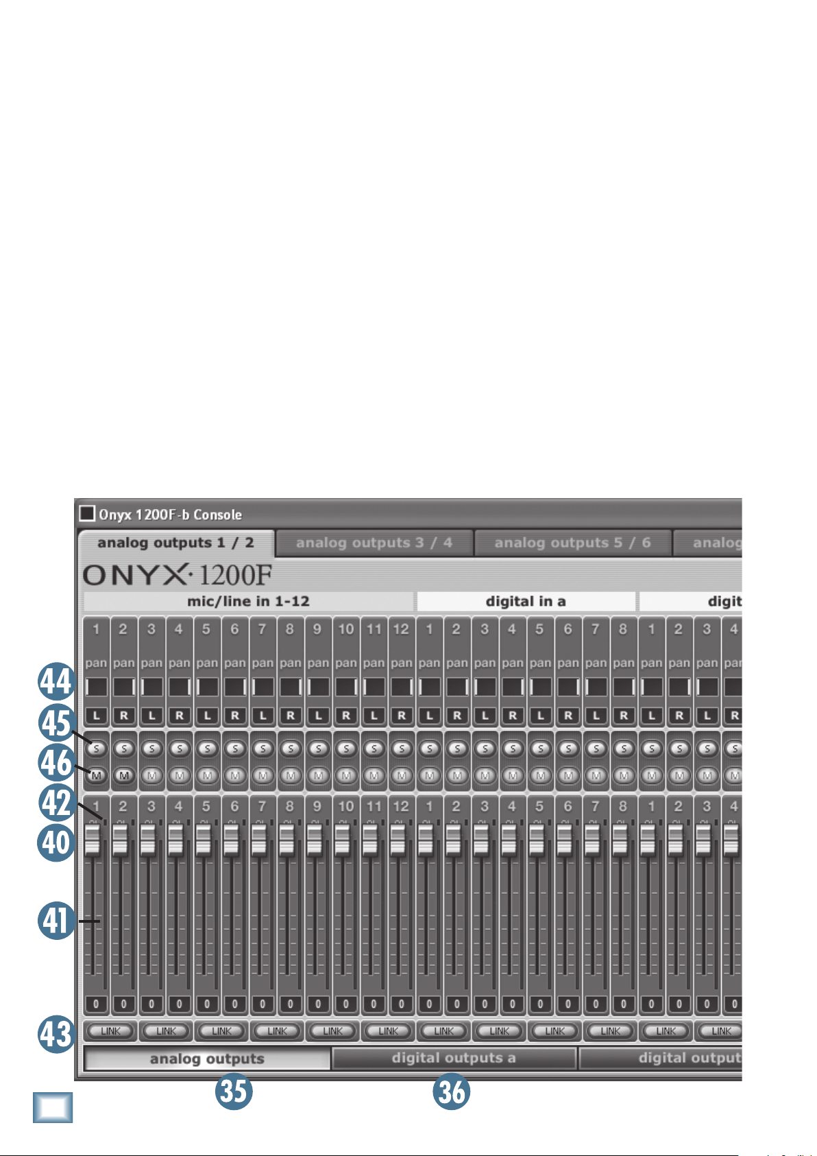
When 176.4/192 kHz sample rate is selected, 8 inputs
and 8 outputs are available. Again, you can modify the
default settings by deselecting one or more pairs of
audio streams and selecting other pairs. As soon as all of
the available audio streams are used up, the remaining
inputs and outputs are “greyed” out.
To summarize, since the audio stream count is reduced at the higher sample rates, the stream selection
matrix lets you decide which audio streams to use for
ONYX 1200F
your own application.
Outputs
Click one of the four buttons at the bottom of the Console window to select a group of outputs (analog outputs
[35], digital outputs a [36], digital outputs b [37], and
headphones [38]).
The tabs at the top of the Console window allow you
to create individual mixes for a pair of outputs related
to the group of outputs you have selected. Each pair of
outputs has its own tab, so make sure you have the correct one selected before making any changes.
Note: The mixes you create in the Console matrix
mixing section apply to the physical outputs on the Onyx
1200F (analog outputs 1-8, digital outputs a 1-8, digital
outputs b 1-8, and the SPDIF/AES output). The DAW
application receives inputs independent of the matrix
mixer via the FireWire connection.
Channel Strips
Each output matrix mixer has a channel strip for
each of the 30 inputs for creating an individual stereo
mix at the selected pair of outputs. In addition, a pair of
outputs from the DAW software application [39] can be
included in the mix. This is useful for overdubbing, when
you want to add another track to some tracks that have
already been recorded.
Each input has its own fader control [40], meter [41],
and overload (OL) indicator [42]. Typically, you want
the meters to average around the –10 mark. This allows
10 dB of headroom for peaks. If the signal has lots of
sharp peaks, you may need to reduce the average level a
bit to allow the peaks through without triggering the OL
indicator.
28
ONYX 1200F

ALINKbutton[43]allowsyoutolinkthefadersofadjacent channels (odd/even pair) so they move together
when using them as a stereo pair.
A pan control [44] allows you to pan the signal
leftandrightbetweenthepairofoutputs(left=odd;
right=even).
Each input has a SOLO button [45] and a MUTE button [46]. When a SOLO button is clicked, the Rude Solo
LED [47] blinks to remind you that a channel is soloed.
Soloing a channel allows you to hear just that channel
in the outputs. Muting a channel allows you to remove a
channel from the overall mix.
There is a Master Level control [48] for the two
outputs and a left and right meter [49] to indicate the
signal level at the outputs. Overload (OL) indicators
[50] let you know if you need to reduce the Main Mix
level control.
There are also indicators [51] that let you know when
Owner’s Manual
MIDI data is being transmitted on any of the MIDI ports
on the Onyx 1200F.
Standalone Mode
When the Console software application is closed, the
Onyx 1200F continues to operate with whatever settings
were present when the Console was closed. When the
Onyx 1200F is turned off, the current settings are saved
to its internal flash memory, and recalled when the
1200F is turned back on.
This allows you to setup the Onyx 1200F for a particular application, such as a 12-channel mic pre or a 12x2
mixer, and use it in that application without having it
connected to a computer.
Owner’s Manual
29

Appendix A: Service Information
If you think your Mackie product has a problem,
please check out the following troubleshooting tips and
do your best to confirm the problem. Visit the Support
section of our website (www.mackie.com/support)
where you will find lots of useful information such as
FAQs, documentation, and user forums. You may find
ONYX 1200F
the answer to the problem without having to send your
Mackie product away.
Troubleshooting
No Power
• Ourfavoritequestion:Isitpluggedin?
• Makesurethepowercordissecurelyseatedinthe
IEC socket [34] and plugged all the way into the
AC outlet.
• MakesuretheACoutletislive(checkwithatester
or lamp).
• IsthePOWER[20]switchon?Makesurethe
POWER switch on the front panel is in the ON position (up).
• AreanyLEDsonthefrontpanelilluminated?One
of the clock, metering, and sample rate LEDs
should be lit. If not, make sure the AC outlet is live.
• Areallthelightsoutinyourbuilding?Ifso,contact
your local power company to get power restored.
• IftherearenoLEDsilluminatedonthefrontpanel,
and you are certain that the AC outlet is live, it will
be
necessary to have your Onyx 1200F serviced. There
are no user serviceable parts inside. Refer to “Repair”
at the end of this section to find out how to proceed.
Bad Channel
• IstheinputGAINcontrol[4]forthechannel
turned up (channels 1-12)?
• Isthesignalsourceturnedup?Makesurethesignal
level from the selected input source is high enough
to light up some of the INPUT meter [1] LEDs for
that channel (channels 1-12).
•
If it is channel 11 or 12, make sure the Instrument
switch [6] is in the right position.
• Trythesamesourcesignalinanotherchannel,set
up exactly like the suspect channel.
Bad Output
• IftheDSPMixeristurnedonintheConsole,make
sure the output level control for the suspect output
30
ONYX 1200F
is turned up and the meters are indicating that a
signal is present.
• Ifanotheroutputisworkingcorrectly,tryswitching
the output connections between the working output
and the suspect output. If the working output stops
working, it could be a bad cable or the device to
which it is connected.
• Ifit’stheS/PDIFOUT[28],makesuretheS/PDIF
Format is set to Consumer in the Console Settings
window. If it is set to Consumer and is not working,
try using the Professional setting.
Bad Sound
• Istheinputconnectorpluggedcompletelyintothe
jack?
• Isitloudanddistorted?MakesuretheinputGAIN
control for the channel is set correctly. Reduce the
signal level on the input source if possible.
• AretheOnyx1200Fandthedevicetowhichitis
connected locked to the same clock? If the Onyx
1200F is operating on its own internal sample rate,
make sure the device to which it is connected is set
to external clock and is locking to the clock signal
eitherthroughtheWORDCLOCKOUT,ADATOUT,
or the S/PDIF connections. If the Onyx 1200F is set
to external Word Clock, make sure it is locked to
the external clock.
• Ifpossible,listentothesignalwithheadphones
plugged into the input source device. If it sounds
bad there, it’s not the Onyx causing the problem.
Noise/Hum
• Turndowneachchannel,onebyone.Ifthenoise
disappears, it’s coming from whatever is plugged
into that channel.
• Checkthesignalcablesbetweentheinputsources
and the Onyx. Disconnect them one by one. When
the noise goes away, you’ll know which input source
is causing the problem.
• Sometimesithelpstoplugalltheaudioequipment
into the same AC circuit so they share a common
ground.
No Audio into your Computer
• ConrmthattheOnyx1200Fisreceivingmicor
line-level input signals (the meters should indicate
signal is present in the Onyx 1200F Console).
• Makesurethecorrectaudiointerfaceisselectedin
the DAW. In Tracktion, this is selected in the Settings tab under Audio Devices.

• IftheOnyx1200Fseemstobeworkingneandyou
are using Tracktion, click Restart Device in the Settings tab under Audio Devices. Other DAW applications may have a similar button.
• InTracktion,besurethecorrectinputsareselected
and the tracks are armed.
• RestartyourOnyx1200Fandcomputer.
• ReinstallthedriversfromtheCD.
Glitchy/Distorted Audio into your Computer
• Increasethebuffersize.Thiscanbedoneinyour
DAW application.
Repair
For warranty repair or replacement, refer to the war-
ranty information on page 39.
Owner’s Manual
Non-warranty repair for Mackie products is available
at a factory-authorized service center. To locate your
nearest service center, visit www.mackie.com, click
“Support” and select “Locate a Service Center.” Service
for Mackie products living outside the United States can
be obtained through local dealers or distributors.
If you do not have access to our website, you can
call our Tech Support department at 1-800-898-3211,
Monday-Friday, 7 am to 5 pm Pacific Time, to explain the
problem. Tech Support will tell you where the nearest
factory-authorized service center is located in your area.
Need Help?
• Visit www.mackie.com and click Support to find:
FAQs (Frequently Asked Questions), manuals, addendums, and
user forums.
• Email us at: techmail@mackie.com.
• Telephone 1-800-898-3211 to speak with one of our splendid
technical support representatives (Monday through Friday,
from 7 AM to 5 PM PST).
Owner’s Manual
R
31
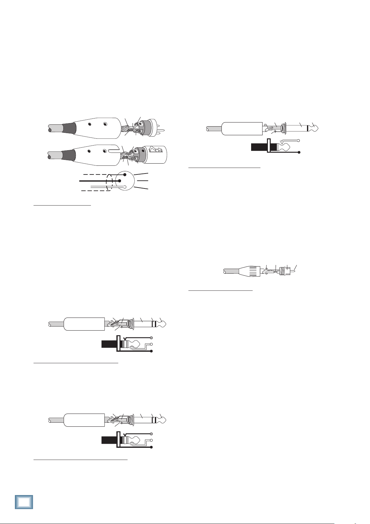
Appendix B: Connections
P
XLR Connectors
Inputs 1-12 accept 3-pin male XLR connectors on
the Neutrik combo inputs. They are wired as follows,
according to standards specified by the AES (Audio
Engineering Society).
ONYX 1200F
HOT
1
2
HOT
2
1
3
1
3
2
SHIELD
COLD
HOT
SHIELD
COLD
SHIELD
COLD
3
XLRBalancedWiring:
Pin 1 = Shield
Pin 2 = Hot (+)
Pin 3 = Cold (–)
1/4" TRS Phone Plugs and Jacks
1/4" TS Phone Plugs and Jacks
“TS” stands for Tip-Sleeve, the two connection points
available on a mono 1/4" phone jack or plug. They are
used for unbalanced signals like the high-impedance
instrument inputs on the Onyx 1200F.
TIP
SLEEVE
TIP
SLEEVE
TIP
SLEEVE
1/4"TSUnbalancedWiring:
Sleeve = Shield
Tip = Hot (+)
RCA Plugs and Jacks
RCA-type plugs (also known as phono plugs) and jacks
are often used in home stereo and video equipment, and
to make S/PDIF connections on consumer digital audio
devices. They are unbalanced and electrically equivalent to a 1/4" TS phone plug.
“TRS” stands for Tip-Ring-Sleeve, the three connection
points available on a stereo 1/4" or balanced phone
jack or plug. TRS jacks and plugs are used for balanced
signals and stereo headphones.
Balanced Mono
SLEEVERING
TIP
1/4"TRSBalancedMonoWiring:
Sleeve = Shield
Tip = Hot (+)
Ring = Cold (–)
SLEEVE
RING
TIP
RING
TIP
SLEEVE
Stereo Headphones
SLEEVERING
TIP
1/4"TRSStereoUnbalancedWiring:
Sleeve = Shield
Tip = Left
Ring = Right
SLEEVE
RING
TIP
RING
TIP
SLEEVE
RCAUnbalancedWiring:
Sleeve = Shield
Tip = Hot (+)
TI
SLEEVE
TIPSLEEVE
32
ONYX 1200F

Unbalancing a Line
Owner’s Manual
FireWire Connection
In most studio, stage, and sound reinforcement situations, there is a combination of balanced and unbalanced inputs and outputs on the various pieces of
equipment. This usually will not be a problem in making
connections.
• Whenconnectingabalancedoutputtoanunbalanced input, be sure the signal high (hot) connections are wired to each other, and that the balanced
signal low (cold) goes to the ground (earth)
connection at the unbalanced input. In most cases,
the balanced ground (earth) will also be connected
to the ground (earth) at the unbalanced input. If
there are ground-loop problems, this connection
may be left disconnected at the balanced end.
• Whenconnectinganunbalancedoutputtoabalanced input, be sure that the signal high (hot)
connections are wired to each other. The unbalanced ground (earth) connection should be wired
to the low (cold) and the ground (earth) connections of the balanced input. If there are ground-loop
problems, try disconnecting the unbalanced ground
(earth) connection from the balanced input ground
(earth) connection, leaving the unbalanced ground
connected to the balanced input low (cold) connection only.
The Onyx 1200F is equipped with two 6-pin FireWire
connectors and comes with a 6-pin to 6-pin FireWire
cable. This works with Macintosh laptops and desktops,
and most PC desktops with a built-in FireWire connector or with a PCI or PCMCIA FireWire card added.
Many laptops have a 4-pin FireWire connector. If this
is the case, you will need to purchase a 6-pin to 4-pin
FireWire adapter cable. These are readily available at
computer stores or online.
2 4 6
1 3 5
6-pin Male FireWire
6-pinFireWireWiring:
Pin 1 = Power
Pin 2 = Ground
Pin 3 = TPB–
Pin 4 = TPB+
Pin 5 = TPA–
Pin 6 = TPA+
1 2 3 4
4-pin Male FireWire
4-pinFireWireWiring:
Pin 1 = TPB–
Pin 2 = TPB+
Pin 3 = TPA–
Pin 4 = TPA+
In some cases, you may have to make up special
adapters to interconnect your equipment. For example,
you may need a balanced XLR female connected to an
unbalanced 1/4" TS phone plug. Many common adapters
can be found at your local electronics supply store.
Mults and “Y”s
A mult or “Y” connector allows you to route one output
to two or more inputs by simply providing parallel wiring connections. You can make “Y”s and mults for the
outputs of both unbalanced and balanced circuits.
Remember: Only mult or “Y” an output into several
inputs. If you need to combine several outputs into one
input, you must use a mixer, not a mult or a “Y.”
Y-Cord Splitter
Owner’s Manual
33

Appendix C: Technical Info
Onyx 1200F Specifications
Frequency Response
Mic Input to Control Room Output (Gain @ unity):
@48 kHz
ONYX 1200F
+0, –3 dB, 10 Hz to 23 kHz
@96 kHz
+0, –3 dB, 10 Hz to 45 kHz
@192 kHz
+0, –3 dB, 10 Hz to 75 kHz
Mic Input to Digital Output
(AES, 192 kHz sample rate, Gain @ unity):
+0, –1 dB, 10 Hz to 86 kHz
Mic Input to Digital Output
(AES, 192 kHz sample rate, Gain @ max):
+0, –3 dB, 15 Hz to 70 kHz
Hi-Z Instr Input to Digital Output
(AES, 192 kHz sample rate, Gain @ max):
+0, –1 dB, 10 Hz to 86 kHz
ADAT Input to ADAT Output (48 kHz sample rate):
+0, –0.01 dB, 17 Hz to 23 kHz
Digital AES Input to Headphones Output
(192 kHz sample rate):
+0, –1 dB, 10 Hz to 55 kHz
Distortion (THD + N)
Mic Input to Line Output (@ +4 dBu output):
1 kHz input
Mic/Line Input to Digital Output (AES, 48 kHz sample rate):
THD+N: < 0.004% @ 1 kHz, +12 dBu input,
gain at unity, 150Ω source
Hi-Z (Instr) Input to Digital Output (AES, 48 kHz sample rate):
THD+N: < 0.01% @ 1 kHz, 100 mV rms input,
gain at –5 dBFS, 150Ω source
Digital Input (AES) to Analog Outs, (48 kHz sample rate):
THD+N: < 0.004%, 10 Hz-22 kHz BW,
–5 dBFS input, +12 dBu output
THD+N: < 0.006%, 10 Hz to 22 kHz BW,
@ +12 dBu, preamp at unity gain
Dynamic Range
113 dB (Mic/Line In to Digital AES Out, A-weighted)
101 dB (Hi-Z Instr In to Digital AES Out, A-weighted)
103 dB
107 dB (Digital AES In to Control Room/Line Outs,
A-weighted)
(Digital AES In to Headphones Out, A-weighted)
Noise
Signal-to-Noise:
150Ω source, 10 Hz-22 kHz BW, Gain @ unity,
48 kHz sample rate)
150Ω source, 10 Hz-22 kHz BW, Gain @ unity,
48 kHz sample rate)
>90 dB (ref. +4 dBu, Mic In to Digital AES Out,
150Ω source, 10 Hz-22 kHz BW, Gain @ unity,
48 kHz sample rate)
output level set to +4 dBu, 48 kHz sample rate)
Equivalent Input Noise (E.I.N.), 20 Hz to 20 kHz BW,
150Ω source impedance:
Residual Noise:
–113 dBFS (Digital AES Out, 10 Hz-22 kHz BW,
48 kHz sample rate)
< –90 dBu (Control Room Out, Gain @ max,
10 Hz-22 kHz BW)
< –86 dBu (Headphones Out, Gain set to 0 dBu out
into 600Ω, 10 Hz-22 kHz BW, 48 kHz sample rate)
>81 dB (ref. +4 dBu, Mic In to Line Out,
>82 dB (ref. +4 dBu, Mic In to Control Room Out,
>88 dB
(Digital AES In to Analog Out, 10 Hz-22 kHz BW,
–129 dBu @ +60 dB gain (Mic In to Control Room Out)
Common Mode Rejection Ratio (CMRR)
Mic In: >60 dB @ 1 kHz, Gain @ maximum
Crosstalk
Mic Input to Control Room Output:
< –88 dB @ 1 kHz, +10 dBu signal on adjacent input,
unity gain, 150Ω source impedance
Mic Input to Digital AES Output:
< –76 dB @ 1 kHz, –50 dBu signal on adjacent input,
maximum gain, 150Ω source impedance
Mic Input to Digital AES Output:
unity gain, 150Ω source impedance
< –110 dB @ 1 kHz, +10 dBu signal on adjacent input,
Input Gain Control Range
Mic In: 0 dB to +60 dB
Line In: –20 dB to + 40 dB
Phantom Power
+48 VDC
Rated Output
Line: +4 dBu
Maximum Rated Output:
+21 dBu @ balanced line-level outputs
34
ONYX 1200F

Input Impedance
13.0 in/330 mm
17.5 in/445 mm
Mic Input: 2.4 kΩ balanced
Inst Input: 1 MΩ
Line: 30 kΩ balanced, 15 kΩ unbalanced
Output Impedance
Line: 150Ω balanced
Signal Level LEDs
–40 dB, –20 dB, –10 dB (normal operating level),
OL = 22 dBu
Sample Frequency Selections
44.1 kHz, 48 kHz, 88.2 kHz, 96 kHz,
176.4 kHz, 192 kHz
Analog Input Connectors
12 balanced XLR/TRS mic/line inputs
Two unbalanced 1/4" TS line/high-impedance
instrument inputs
One balanced XLR talkback mic input
Two balanced 1/4" TRS line-level insert returns
Analog Output Connectors
Eight balanced line-level outputs on DB-25
Four unbalanced 1/4" TRS stereo headphone outputs
Two balanced 1/4" TRS line-level insert sends
Four balanced 1/4" TRS control room line-level outputs
Digital Output Connectors
Owner’s Manual
One BNC connector for external word clock output
One RCA connector for S/PDIF output
One XLR-M connector for AES/EBU output
Two 5-pin DIN connectors for MIDI output
Two Toslink optical connectors for ADAT output
DSP
TMS320C6713 Floating-Point Digital Signal Processor
operating at 225 MHz, delivering up to 1350 million
floating-point operations per second (MFLOPS),
1800 million instructions per second (MIPS), and
450 million multiply-accumulate operations per
second (MMACS)
AC Power Requirements
Power Consumption: 45 watts
Universal AC Power Supply:
100 VAC – 240 VAC, 50-60 Hz
Physical Dimensions and Weight
Height: 3.50 in/89 mm
Width: 17.5 in/445 mm (main body of unit)
19.0 in/483 mm (with rack ears)
Depth: 14.5 in/368 mm (including front knobs and
rear BNC jack)
Weight: 13.8 lb/6.3 kg
Digital Input Connectors
One BNC connector for external word clock input
One RCA connector for S/PDIF input
One XLR-F connector for AES/EBU input
Two 5-pin DIN connectors for MIDI input
Two Toslink optical connectors for ADAT input
Two 6-pin FireWire input/output
14.5 in/368 mm
LOUD Technologies Inc. is always striving to improve our products by incorporating new and improved materials, components,
and manufacturing methods. Therefore, we reserve the right to
change these specifications at any time without notice.
“Mackie.”, “Onyx,” and the “Running Man” are registered
trademarks of LOUD Technologies Inc. All other brand names
mentioned are trademarks or registered trademarks of their
respective holders, and are hereby acknowledged.
©2007-2012 LOUD Technologies Inc. All Rights Reserved.
WEIGHT
13.8 lb/
6.3 kg
3.5 in/
89 mm
19.0 in/483 mm
2 1 3 4 5 6 7 8 9 10 11 12
(2 rack spaces)
Owner’s Manual
35

Onyx 1200F Block Diagram
OL
-10
-20
-30
OL
-10
-20
-30
OL
-10
-20
-30
OL
-10
-20
-30
MIDI IN
MIDI OUT
FIREWIRE IN
INT
CLOCK
SOURCE
CHANNEL 1
METERS
CHANNEL 2
CHANNEL 3
CHANNEL 4
WORD
AES
S/PDIF
ADAT-1
ADAT-2
OL
-10
-20
-30
OL
-10
-20
-30
OL
-10
-20
-30
OL
-10
-20
-30
CHANNEL 5
CHANNEL 6
CHANNEL 7
CHANNEL 8
OL
-10
-20
-30
OL
-10
-20
-30
OL
-10
-20
-30
OL
-10
-20
-30
CHANNEL 9
CHANNEL 10
CHANNEL 11
CHANNEL 12
IN-A
METERING
OUT-D1
OUT-D2
OUT-A
44.1kHz
SAMPLE
RATE
48kHz
88.2kHz
176.4kHz
192kHz
96kHz
Phantom
Talkback
Mic
2
3
1
48V
Talk To Phones
Level
+
-
Talkback
ON/OFF
V+
jumper
J24
ONYX 1200F
Ch 1-12
48V
Phantom
Channel 1-2
Mic
Line
48V
Phantom
Channel 3-10
Mic
Line
48V
Phantom
Channel 11-12
Mic
Line
Instrument
Insert
Mic
2
1
3
+
-
2
1
3
+
-
2
1
3
+
-
Line (–20 dB)
Mic
Line (–20 dB)
Mic
Line (–20 dB)
Gain
+
-
XDR
Preamp
Gain
+
-
XDR
Preamp
Mic/Line
Instrument
Mic: 0 to +60 dB
Line: –20 to +40 dB
Mic: 0 to +60 dB
Line: –20 to +40 dB
Gain
Mic: 0 to +60 dB
Line: –20 to +40 dB
+
-
XDR
Preamp
A/D Converter
24-bit/192 kHz
36
ONYX 1200F

Owner’s Manual
DSP
(a.k.a.
BRAIN)
Digital
Audio
Mixer/Router
30 input x
34 output
OL
-10
-20
-30
Firewire
I/O
S/PDIF
I/O
Ch 1-12
Decoder
OL
-10
-20
-30
OL
-10
-20
-30
OL
-10
-20
-30
MIDI IN
MIDI OUT
FIREWIRE IN
INT
CLOCK
SOURCE
CHANNEL 1
METERS
CHANNEL 2
CHANNEL 3
CHANNEL 4
WORD
AES
S/PDIF
ADAT-1
ADAT-2
OL
-10
-20
-30
OL
-10
-20
-30
OL
-10
-20
-30
OL
-10
-20
-30
CHANNEL 5
CHANNEL 6
CHANNEL 7
CHANNEL 8
OL
-10
-20
-30
OL
-10
-20
-30
OL
-10
-20
-30
OL
-10
-20
-30
CHANNEL 9
CHANNEL 10
CHANNEL 11
CHANNEL 12
IN-A
METERING
OUT-D1
OUT-D2
OUT-A
44.1kHz
SAMPLE
RATE
48kHz
88.2kHz
176.4kHz
192kHz
96kHz
Word Clock
I/O
MIDI 1
I/O
Firewire
I/O
AES/EBU
I/O
ADAT A
I/O
MIDI 2
I/O
Phones 1
Phones 1
Phones 2
Level
Control Rm Monitors A
Left
Right
Phones 2
Level
Mon A/B
Footswitch
Control Rm Monitors B
Left
Right
Conversion
Mon A/B
Logic
Phones 3
Phones 3
Phones 4
Level
Phones 4
Level
D/A
Conversion
ADAT B
I/O
Monitor
A/B
D/A
AB
Control Room
Level
V+
N/C
N/C
Phantom
Talkback
Mic
2
3
1
48V
Talk To Phones
Level
+
-
Talkback
ON/OFF
V+
N/C
Talkback
Footswitch
Talkback
Logic
jumper
J24
Bal Line Out 1
Bal Line Out 8
D/A
Conversion
Out 1-8
Outputs 1-8
Level
Out
1-8
Bypass
ON/OFF
Digital Level
Control
Phantom
CHANNEL 1
CHANNEL 2
CHANNEL 3
CHANNEL 4
CHANNEL 5
CHANNEL 6
CHANNEL 7
CHANNEL 8
CHANNEL 9
CHANNEL 10
CHANNEL 11
CHANNEL 12
METERING
48V
Talkback
Mic
CLOCK
SOURCE
SAMPLE
RATE
J24
jumper
1
METERS
OL
-10
-20
-30
OL
-10
-20
-30
OL
-10
-20
-30
OL
-10
-20
-30
OL
-10
-20
-30
OL
-10
-20
-30
OL
-10
-20
-30
OL
-10
-20
-30
OL
-10
-20
-30
OL
-10
-20
-30
OL
-10
-20
-30
OL
-10
-20
-30
INT
WORD
AES
S/PDIF
ADAT-1
ADAT-2
IN-A
OUT-D1
OUT-D2
OUT-A
44.1kHz
48kHz
88.2kHz
96kHz
176.4kHz
192kHz
MIDI IN
MIDI OUT
FIREWIRE IN
Talk To Phones
2
3
Talkback
ON/OFF
Level
+
-
V+
Decoder
N/C
Talkback
Logic
Ch 1-12
DSP
(a.k.a.
BRAIN)
Digital
Audio
Mixer/Router
30 input x
34 output
Out
1-8
Outputs 1-8
D/A
Conversion
Digital Level
Control
Level
D/A
Conversion
Monitor
Control Room
Level
A/B
Bypass
ON/OFF
AB
Mon A/B
Logic
Phones 1
Level
Phones 2
Level
Phones 3
Level
Phones 4
Level
N/C
N/C
D/A
Conversion
Firewire
I/O
Firewire
I/O
AES/EBU
I/O
S/PDIF
I/O
ADAT A
I/O
ADAT B
I/O
Word Clock
I/O
MIDI 1
I/O
MIDI 2
I/O
V+
Out 1-8
Left
Control Rm Monitors A
Right
Left
Control Rm Monitors B
Right
Mon A/B
Footswitch
Phones 1
Phones 2
Phones 3
Phones 4
Talkback
Footswitch
Bal Line Out 1
Bal Line Out 8
Owner’s Manual
37

B
A
CONTROL ROOM
ONYX 1200F
ADAT-2 FWADAT-1INT WORD AES
CLOCK SOURCE
STUDIO RECORDING PREAMP WITH 192kHz FIREWIRE I/O
A/BBYPASS
ON
S/PDIF
OL
OL
OL
OL
OL
OL
OL
OL
OL
OL
21 3 4 5 6 7 8 9 10 11 12
OL
OL
METERING
-10
-10
-10
-10
-10
-10
-10
-10
-10
-10
-10
-10
MIDI
MIDI
IN-A OUT-D OUT-A
RETURN
B
B
E
R
P
C
I
M
X
Y
N
O
E
R
P
C
I
M
X
Y
N
O
E
R
P
C
I
M
X
Y
N
O
E
R
P
C
I
M
X
Y
N
O
E
R
P
C
I
M
X
Y
N
O
E
R
P
C
I
M
X
Y
N
O
E
R
P
C
I
M
X
Y
N
O
E
R
P
C
I
M
X
Y
N
O
E
R
P
C
I
M
X
Y
N
O
E
R
P
C
I
M
X
Y
N
O
E
R
P
C
I
M
X
Y
N
O
12 11 10 9 8 7 6 5 4 3 2 1
E
R
P
C
I
M
X
Y
N
O
FOOTSWITCH
A/B
MON
~100-240 VAC
50-60Hz 45W
TALK
BACK
LINE LEVEL OUTPUT
8 CHANNEL BALANCED
MAX
OO
MAX
O
MAX
OO
OUT
IN
SAMPLE RATE
MONITOR
OUTPUTS 1-8
TALK TO
PHONES
176.4kHz44.1kHz 96kHz48kHz 88.2kHz 192kHz
PHONES
2 3 4
1
11
ON
SEND
(BALANCED)
INSERTS
(48V)
MIC
TALKBACK
A
CONTROL RM MONITORS
L 2 1 R
UNBAL
MAX
OO
MAX
OO
MAX
OO
MAX
OO
12
UNBAL
OUT
60
40
ONYX
+40dB
30
48V
LINE
20
-40-
U
20
40
30
48V
LINE
20
-40-
U
20
40
30
48V
LINE
20
-40-
U
20
40
30
48V
LINE
20
-40-
U
20
40
30
48V
LINE
20
-40-
U
20
40
30
48V
LINE
20
-40-
U
20
40
30
48V
LINE
20
-40-
U
20
40
30
48V
LINE
20
-40-
U
20
40
30
48V
LINE
20
-40-
U
20
40
30
48V
LINE
20
-40-
U
20
40
30
48V
LINE
20
-40-
U
20
40
30
48V
LINE
20
-40-
U
20
MIC PRE
GAIN
U
-20dB
60
ONYX
+40dB
MIC PRE
GAIN
U
-20dB
60
ONYX
MIC PRE
+40dB
GAIN
U
-20dB
60
ONYX
MIC PRE
+40dB
GAIN
U
-20dB
60
ONYX
MIC PRE
+40dB
GAIN
U
-20dB
60
ONYX
MIC PRE
+40dB
GAIN
U
-20dB
60
ONYX
MIC PRE
+40dB
GAIN
U
-20dB
60
ONYX
MIC PRE
+40dB
GAIN
U
-20dB
60
ONYX
MIC PRE
+40dB
GAIN
U
-20dB
60
ONYX
MIC PRE
+40dB
GAIN
U
-20dB
60
ONYX
MIC PRE
+40dB
GAIN
U
-20dB
60
ONYX
MIC PRE
+40dB
GAIN
U
-20dB
AES/EBU
ADAT
IN OUT
MIDI 2
IN
OUT
MIDI 1
IN
FIREWIRE
OUT IN
S/PDIF
A
EXTERNAL
WORD CLOCK
OUT
IN
OUT
IN
38
ONYX 1200F

Onyx 1200F Limited Warranty
Please keep your sales receipt in a safe place.
A. LOUD Technologies Inc. warrants all materials,
workmanship and proper operation of this product for a period
of one year from the original date of purchase. You may
purchase an additional 24-month Extended Warranty (for a
total of 36 months of coverage). Visit our website and follow
the “Product Registration” links for details (www.mackie.com).
If any defects are found in the materials or workmanship or
if the product fails to function properly during the applicable
warranty period, LOUD Technologies, at its option, will repair
or replace the product.
sold and delivered within the U.S. and Canada by LOUD
Technologies Inc. or its authorized dealers.
B. For faster processing (not to mention a free gift), register
online or mail in the product registration card.
C. Unauthorized service, repairs, or modification of Mackie
products will void this warranty. To obtain repairs or
replacement under warranty, you must have a copy of your
sales receipt from the authorized Mackie dealer where you
purchased the product. It is necessary to establish purchase
date and determine whether your Mackie product is within
the warranty period.
D. To obtain warranty repair or replacement:
1.
2.
3. Repair: When you call Mackie Technical Support,
•Packtheproductinitsoriginalshippingcarton.Also
•Shiptheproductinitsoriginalshippingcarton,
Note: Under the terms of the warranty, you must ship
Note: You must have a sales receipt from an authorized
Call Mackie Technical Support at 800/898-3211, 7 AM
to 5 PM Monday through Friday (Pacific Time) to get
authorization for repair or replacement. Alternately, go to
the Mackie website, click “Support” (www.mackie.com/
support), and follow the instructions for reporting a warranty
issue and submitting a request for an advance replacement.
Advance Replacement: Mackie will ship a replacement
unit to you along with an invoice for the suggested
retail price of the replacement unit. You must return the
defective unit immediately to cancel the invoice. If you do
not return the defective unit within 30 days, you must pay
the full amount stated in the invoice to satisfy your debt.
explain the problem and obtain a Service Request
Number. Have your Mackie product’s serial number
ready. You must have a Service Request
Number before you can obtain factoryauthorized service.
include a note explaining exactly how to duplicate the
problem, a copy of the sales receipt with price and date
showing, your daytime phone number and return street
address (no P.O. boxes or route numbers, please!), and
the Service Request Number. If we cannot duplicate the
problem or establish the starting date of your Limited
Warranty, we may, at our option, charge for service time
and parts.
freight prepaid to the authorized service center. Write
the Service Request Number in BIG PRINT on top of
the box. The address of your closest authorized service
center will be given to you by Technical Support, or it
may be obtained from our website. Once it’s repaired,
the authorized service center will ship it back by ground
shipping, pre-paid (if it qualified as a warranty repair).
or drop-off the unit to an authorized service center.
The return ground shipment is covered for those units
deemed by us to be under warranty.
Mackie dealer for your unit to be considered for
warranty repair.
This warranty applies only to equipment
IMPORTANT: Make sure that the Service Request
Number is plainly written on the shipping carton. No
receipt, no warranty service.
E. LOUD Technologies reserves the right to inspect any
products that may be the subject of any warranty claims before
repair or replacement is carried out. LOUD Technologies may,
at our option, require proof of the original date of purchase in
the form of a dated copy of the original dealer’s invoice or sales
receipt. Final determination of warranty coverage lies solely
with LOUD Technologies.
F. Any products returned to one of the LOUD Technologies
factory-authorized service centers, and deemed eligible
for repair or replacement under the terms of this warranty
will be repaired or replaced. LOUD Technologies and its
authorized service centers may use refurbished parts for repair
or replacement of any product. Products returned to LOUD
Technologies that do not meet the terms of this Warranty
will not be repaired unless payment is received for labor,
materials, return freight, and insurance. Products repaired
under warranty will be returned freight prepaid by LOUD
Technologies to any location within the boundaries of the USA
or Canada.
G. LOUD Technologies warrants all repairs performed
for 90 days or for the remainder of the warranty period.
This warranty does not extend to damage resulting from
improper installation, misuse, neglect or abuse, or to exterior
appearance. This warranty is recognized only if the inspection
seals and serial number on the unit have not been defaced or
removed.
H. LOUD Technologies assumes no responsibility for the
timeliness of repairs performed by an authorized service
center.
I. This warranty is extended to the original purchaser. This
warranty may be transferred to anyone who may subsequently
purchase this product within the applicable warranty period
for a nominal fee. A copy of the original sales receipt is
required to obtain warranty repairs or replacement.
J. This is your sole warranty. LOUD Technologies does not
authorize any third party, including any dealer or sales
representative, to assume any liability on behalf of LOUD
Technologies or to make any warranty for LOUD Technologies
Inc.
K. THE WARRANTY GIVEN ON THIS PAGE IS THE SOLE
WARRANTY GIVEN BY LOUD TECHNOLOGIES INC.
AND IS IN LIEU OF ALL OTHER WARRANTIES, EXPRESS
AND IMPLIED, INCLUDING THE WARRANTIES OF
MERCHANTABILITY AND FITNESS FOR A PARTICULAR
PURPOSE. THE WARRANTY GIVEN ON THIS PAGE SHALL BE
STRICTLY LIMITED IN DURATION TO ONE YEAR FROM THE
DATE OF ORIGINAL PURCHASE FROM AN AUTHORIZED
MACKIE DEALER. UPON EXPIRATION OF THE APPLICABLE
WARRANTY PERIOD, LOUD TECHNOLOGIES INC. SHALL
HAVE NO FURTHER WARRANTY OBLIGATION OF ANY
KIND. LOUD TECHNOLOGIES INC. SHALL NOT BE LIABLE
FOR ANY INCIDENTAL, SPECIAL, OR CONSEQUENTIAL
DAMAGES THAT MAY RESULT FROM ANY DEFECT IN THE
MACKIE PRODUCT OR ANY WARRANTY CLAIM. Some states
do not allow exclusion or limitation of incidental, special, or
consequential damages or a limitation on how long warranties
last, so some of the above limitations and exclusions may not
apply to you. This warranty provides specific legal rights and
you may have other rights which vary from state to state.
Owner’s Manual
Owner’s Manual
39

16220 Wood-Red Road NE • Woodinville, WA 98072 • USA
United States and Canada: 800.898.3211
Europe, Asia, Central and South America: 425.487.4333
Middle East and Africa: 31.20.654.4000
Fax: 425.487.4337 • www.mackie.com
E-mail: sales@mackie.com
 Loading...