

Page 1

MX2500 • MX3500
Professional Power Amplifiers
OWNER’S MANUAL
Page 2
Important Safety Instructions
1. Read these instructions.
2. Keep these instructions.
3. Heed all warnings.
4. Follow all instructions.
5. Do not use this apparatus near water.
6. Clean only with a dry cloth.
7. Do not block any ventilation openings. Install in accordance
with the manufacturer’s instructions.
8. Minimum distance (5 cm) around the apparatus for sucient ventilation.
The ventilation should not be impeded by covering the ventilation openings
with items, such as newspapers, table-cloths, curtains, etc.
9. Do not install near any heat sources such as radiators, heat registers,
stoves, or other apparatus (including amplifiers) that produce heat.
10. No naked flame sources, such as lighted candles, should be placed
on the apparatus.
11. Do not defeat the safety purpose of the polarized or grounding-type plug.
A polarized plug has two blades with one wider than the other. A grounding-type
plug has two blades and a third grounding prong. The wide blade or the third
prong are provided for your safety. If the provided plug does not fit into your
outlet, consult an electrician for replacement of the obsolete outlet.
12. Protect the power cord from being walked on or pinched particularly at plugs,
convenience receptacles, and the point where they exit from the apparatus.
13. Only use attachments/accessories specified by the manufacturer.
14. Use only with a cart, stand, tripod, bracket, or table
specified by the manufacturer, or sold with the apparatus.
When a cart is used, use caution when moving the cart/
apparatus combination to avoid injury from tip-over.
15. Unplug this apparatus during lightning storms or when
unused for long periods of time.
MX Series Professional Power Amplifiers
16. Refer all servicing to qualified service personnel. Servicing
is required when the apparatus has been damaged in any
way, such as power-supply cord or plug is damaged, liquid has been spilled or
objects have fallen into the apparatus, the apparatus has been exposed to rain
or moisture, does not operate normally, or has been dropped.
17. This apparatus shall not be exposed to dripping or splashing, and no object filled
with liquids, such as vases or beer glasses, shall be placed on the apparatus.
18. Do not overload wall outlets and extension cords as this can result in a risk
of fire or electric shock.
CAUTION
RISK OF ELECTRIC SHOCK! DO NOT OPEN!
CAUTION: TO REDUCE THE RISK OF ELECTRIC SHOCK DO NOT
REMOVE COVER (OR BACK). NO USER-SERVICEABLE PARTS INSIDE.
REFER SERVICING TO QUALIFIED PERSONNEL.
The lightning flash with arrowhead symbol within an equilateral
triangle is intended to alert the user to the prescence of uninsulated
“dangerous voltage” within the product’s enclosure, that may be of
significant magnitude to constitute a risk of electric shock to persons.
The exclamation point within an equilateral triangle is intended
to alert the user of the prescence of important operating and
maintaining (servicing) instructions in the literature accompanying
the appliance.
WARNING — To reduce the risk of fire or electric shock, do not
expose this apparatus to rain or moisture.
CAUTION — To prevent electric shock hazard, do not connect
to mains power supply while grille is removed.
Laite on liitettävä suojakoskettimilla varustettuun pistorasiaan.
Apparatet må tilkoples jordet stikkontakt.
PORTABLE CART
WARNING
19. This apparatus has been designed with Class-I construction and
must be connected to a mains socket outlet with a protective earthing
connection (the third grounding prong).
20. This apparatus has been equipped with a rocker-style AC mains power
switch. This switch is located on the front panel and should remain readily
accessible to the user.
21. The MAINS plug or an appliance coupler is used as the disconnect device,
so the disconnect device shall remain readily operable.
22. The use of apparatus is in tropical and/or moderate climates.
23. NOTE: This equipment has been tested and found to comply with the limits
for a Class B digital device, pursuant to part 15 of the FCC Rules. These
limits are designed to provide reasonable protection against harmful
interference in a residential installation. This equipment generates, uses,
and can radiate radio frequency energy and, if not installed and used in
accordance with the instructions, may cause harmful interference to radio
communications. However, there is no guarantee that interference will not
occur in a particular installation. If this equipment does cause harmful
interference to radio or television reception, which can be determined by
turning the equipment o and on, the user is encouraged to try to correct the
interference by one or more of the following measures:
• Reorient or relocate the receiving antenna.
• Increase the separation between the equipment and the receiver.
• Connect the equipment into an outlet on a circuit dierent from
that to which the receiver is connected.
• Consult the dealer or an experienced radio/TV technician for help.
CAUTION: Changes or modifications to this device not expressly approved
by LOUD Audio, LLC could void the user’s authority to operate the equipment
under FCC rules.
24. This apparatus does not exceed the Class A/Class B (whichever
is applicable) limits for radio noise emissions from digital apparatus
as set out in the radio interference regulations of the Canadian Department
of Communications.
ATTENTION
— Le présent appareil numérique n’émet pas de bruits
radioélectriques dépassant las limites applicables aux appareils
numériques de class A/de class B (selon le cas) prescrites dans
le réglement sur le brouillage radioélectrique édicté par les ministere
des communications du Canada.
25. Exposure to extremely high noise levels may cause permanent hearing loss.
Individuals vary considerably in susceptibility to noise-induced hearing loss,
but nearly everyone will lose some hearing if exposed to suciently intense
noise for a period of time. The U.S. Government’s Occupational Safety and
Health Administration (OSHA) has specified the permissible noise level
exposures shown in the following chart.
According to OSHA, any exposure in excess of these permissible limits
could result in some hearing loss. To ensure against potentially dangerous
exposure to high sound pressure levels, it is recommended that all persons
exposed to equipment capable of producing high sound pressure levels
use hearing protectors while the equipment is in operation. Ear plugs or
protectors in the ear canals or over the ears must be worn when operating
the equipment in order to prevent permanent hearing loss if exposure is in
excess of the limits set forth here:
Duration, per
day in hours
8 90 Duo in small club
6 92
4 95 Subway Train
3 97
2 00 Very loud classical music
.5 02
05 Matt screaming at Troy about deadlines
0.5 0
0.25 or less 5 Loudest parts at a rock concert
Sound Level dBA,
Slow Response
Typical Example
Apparaten skall anslutas till jordat uttag.
Correct disposal of this product: This symbol indicates that this product should not be disposed of with your household waste, according to the WEEE directive (202/9/EU)
and your national law. This product should be handed over to an authorized collection site for recycling waste electrical and electronic equipment (EEE). Improper handling of this type of waste
could have a possible negative impact on the environment and human health due to potentially hazardous substances that are generally associated with EEE. At the same time, your cooperation
in the correct disposal of this product will contribute to the eective usage of natural resources. For more information about where you can drop o your waste equipment for recycling, please
contact your local city oce, waste authority, or your household waste disposal service.
2
MX Series Professional Power Amplifiers
Page 3

Contents Features
Owner’s Manual
Important Safety Instructions ........................................... 2
Contents / Features ............................................................ 3
Introduction / Getting Started ........................................... 4
Hookup Diagrams ............................................................... 5
MX Series Amplifiers: Rear Panel Features.....................0
. Power Connection ...................................................0
2. Circuit Breaker .......................................................0
3. XLR Inputs ..............................................................0
4. XLR Thru Outputs ...................................................0
5. NL4 Speaker Outputs .............................................0
6. Amp Mode Switch...................................................
7. Sensitivity Switch ...................................................
8. Fan Vents ................................................................
MX Series Amplifiers: Front Panel Features ....................2
9. Power Switch ..........................................................2
0. Level Controls .......................................................2
. LEDs .......................................................................2
General Precautions ..........................................................3
AC Power Requirements ............................................3
Thermal Considerations ............................................3
Rack Mounting ...........................................................3
Care and Maintenance ......................................................3
• Aordable, reliable power perfect for DRM Series Passive
Loudspeakers, installations, and production audio systems
• Ultra-lightweight switching power supply for maximum
eciency and minimal heat
• Forced-air ventilation keeps the amplifier running cool
• MX2500 Power output:
o 500W Continuous power @8 Ω per channel
o 750W Continuous power @4 Ω per channel
o 500W Continuous power @ 8 Ω bridged
• MX3500 Power output:
o 000W Continuous power @8 Ω per channel
o 350W Continuous power @4 Ω per channel
o 2700W Continuous power @ 8 Ω bridged
• Selectable parallel/stereo/bridged operating modes
• Independent level control per channel
• Selectable input sensitivity
• Signal, Clip, and Fault LEDs per channel
• Short, under-impedance, over-current and thermal protection
• XLR Input and Thru per channel
• NL4 outputs
• Robust, impact-resistant, all-steel 2U rackmount chassis
Appendix A: Service Information ......................................4
Appendix B: Technical Information ..................................6
MX Series Amplifiers Dimensions.............................7
MX Series Amplifiers Block Diagram ........................8
Limited Warranty ...............................................................9
Not available in the USA, Canada, China, Japan and other
00 – 20V countries
Part No. SW269 Rev. A 0/9
©2019 LOUD Audio, LLC. All Rights Reserved.
Like us
Follow us
Watch our dang videos
Owner’s Manual
3
Page 4

Introduction
Getting Started
MX Series Professional Power Amplifiers provide the power
and performance needed for installation and portable passive
systems.
Utilizing proven Mackie amplifier design history, they deliver
clear, punchy sound that’s distortion-free even when pushed
to the limits.
The MX Series is Built-Like-A-Tank™ but is still easy to lif
thanks to a lightweight and ultra-ecient high-current
switching power supply.
With optimized performance, super-quiet operation and an
array of protection circuits, the MX Series delivers powerful
performance at an aordable price.
Combine with DRM Passive Loudspeakers and the SP260
Loudspeaker Processor for a complete Mackie professional
system.
How to Use This Manual:
MX Series Professional Power Amplifiers
Afer this introduction, a getting started guide will help
you get things set up fast. The hookup diagrams show
some typical MX amplifier setups.
The following steps will help you set up the MX amp quickly.
. Make all initial connections with the power switches
OFF on all equipment. Make sure the master volume, level
and gain controls are all the way down.
2. Connect the outputs from the mixing console (or other
signal source) to the inputs on the rear panel of the power
amplifier.
3. Connect the speaker output from the power amplifier
to the input on the rear panel of the loudspeaker.
4. Push the line cord securely into the amplifier’s / mixer’s
IEC connectors and plug the other ends into grounded
AC outlets. The amplifier / mixer may accept the appropriate
voltage as indicated near the IEC connector.
5. Turn the power amplifier/mixer on. Turn up its volume
or gain control(s) as recommended by the manufacturer.
6. Start the signal source and raise the mixer’s main
L/R fader up to a comfortably loud listening level.
This icon marks information that is critically
important or unique! For your own good, read and
remember them...it is a good idea to pay special
attention to these areas in the Owner’s Manual
marked with the “VERY IMPORTANT” hand icon.
There’s an illustration of a microscope,
so, of course, you’re going to get more
detailed information when you see this little
guy. There are explanations of features
and practical tips listed here.
It’s a good idea to pay attention to text displayed
next to a note icon, as this icon draws attention
to certain features and functions relating to the
usage of the MX Series amplifier.
Please write the serial numbers here for future reference
(i.e., insurance claims, tech support, return authorization,
make dad proud, etc.)
Purchased at:
Date of purchase:
Things to Remember:
• Never listen to loud music for prolonged periods. Please see
the Safety Instructions on page 2 for information on hearing
protection.
• As a general guide, the mixer (or other signal source)
should be turned on first, followed by the amplifier(s).
As such, the amplifiers should also be turned o first,
followed by the mixer. This will reduce the possibility
of any turn-on or turn-o thumps and other noises
generated by any upstream equipment from coming
out of the speakers.
• Save the shipping boxes and packing materials! You may
need them someday. Besides, the cats will love playing
in them and jumping out at you unexpectedly. Remember
to pretend like you are surprised!
• Save your sales receipt in a safe place.
4
MX Series Professional Power Amplifiers
Page 5

Hookup Diagrams
Owner’s Manual
MUTE MUTE MUTE MUTE MUTE MUTE MUTE MUTE MUTE
48V
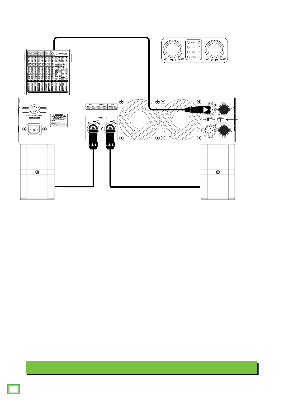
In stereo mode, both gain controls
are used to achieve a nice balance.
Stereo
Displayed above is a fairly typical MX Series amplifier setup. In short, it’s two ins, two outs.
In this example, cables from the mixer’s lef and right main output jacks are connected to the ch. and ch. 2 input
jacks of the MX Series amplifier. The speaker outputs of the MX amp are then connected to the inputs of a pair
of passive loudspeakers [Mackie DRM22-P in this example]. Make sure that the amp mode is set to “stereo”.
Stereo Setup
Owner’s Manual
5
Page 6
Hookup Diagrams continued...
MUTE MUTE MUTE MUTE MUTE MUTE MUTE MUTE MUTE
MX Series Professional Power Amplifiers
48V
In parallel mode, both gain controls
are used to achieve a nice balance.
Parallel
In this example, we’re looking at a parallel setup. You’re sending a mono signal to both outputs.
Here, a cable from the mixer’s lef main output jack is connected to the ch. input jack of the MX Series amplifier.
The speaker outputs of the MX amp are then connected to the inputs of a pair of passive loudspeakers [Mackie DRM22-P
in this example]. Make sure that the amp mode is set to “parallel”.
Parallel Setup
6
MX Series Professional Power Amplifiers
Page 7

Hookup Diagrams continued...
48V
MUTE MUTE MUTE MUTE MUTE MUTE MUTE MUTE MUTE
Owner’s Manual
In bridge mode, only
this gain control is used.
Bridge
AMPLIFIER END
1–
1+
2+
2–
Crossover Cable
Pin 1+ to Pin 1+
Pin 2+ to Pin 1–
COLD
HOT
SPEAKER END
1–
1+
2+
2–
If you have two ampliers, each could power a
single speaker in bridged mono, to make a very
powerful stereo system. Use a stereo feed from
your mixing console, the left goes to one amp,
and the right goes to the other.
Now we’re looking at a bridge setup. Instead of the two ins, two outs of the stereo setup, this is a single in, single out.
A cable from the mixer’s lef main output jack is connected to the ch. input jack of the MX Series amplifier.
The ch. (bridge) speaker output of the MX amp is then connected to the input of a single passive loudspeaker [Mackie
DRM22-P in this example]. Make sure that the amp mode is set to “bridge”.
Bridge Setup
Owner’s Manual
7
Page 8

Hookup Diagrams continued...
MUTE MUTE MUTE MUTE MUTE MUTE MUTE MUTE MUTE
MX Series Professional Power Amplifiers
48V
Stereo
Stereo
This setup starts o looking like the first hookup diagram – Stereo Setup – then gets a little fancy.
Like before, cables from the mixer’s lef and right main output jacks are connected to the ch. and ch. 2 input
jacks of the MX Series amplifier. The speaker outputs of this MX amp are then connected to the inputs of a pair
of passive loudspeakers [Mackie DRM22-P in this example].
The XLR thru jacks of the first MX amp are then connected to the ch. 1 and ch. 2 input jacks of a second MX amp with the
speaker outputs of this MX amp connected to the inputs of a pair of passive subwoofers [Mackie DRM8S-P in this example].
Make sure that the amp mode on both amps is set to “stereo”.
Daisy-Chaining Two Amplifiers
8
MX Series Professional Power Amplifiers
Page 9

Hookup Diagrams continued...
Ch. 1 Ch. 2
48V
MUTE MUTE MUTE MUTE MUTE MUTE MUTE MUTE MUTE
Owner’s Manual
Stereo
AMPLIFIER
END
2+
CH.1 COLD
CH.1 HOT
1–
1+
CH.2 HOT
2–
CH.2 COLD
SPEAKER
END
1–
2+
2–
1+
This last hookup diagram probably won’t be utilized a whole lot, but it is an option.
In this example, cables from the mixer’s lef and right main output jacks are connected to the ch. and ch. 2 input jacks
of the MX Series amplifier. This time, though, only a single speaker output of the MX amp is connected to the input
of a single passive loudspeaker [Mackie DRM22-P in this example]. The output (or thru) jack of the passive loudspeaker
is then connected to the input of another passive loudspeaker. This type of setup would be good for loudspeakers used
as monitors, for example. Make sure that the amp mode is set to “stereo”.
Stereo Speakers with Minimum Length of Speaker Cable Runs
Owner’s Manual
9
Page 10

MX Series Amplifiers: Rear Panel Features
2
3
4
1 5
. Power Connection
This is a standard 3-prong IEC power connector.
Connect the detachable power cord (included in the
packaging with the amplifier) to the power receptacle,
and plug the other end of the power cord into an AC
outlet.
Make sure that the AC power is matched to
the AC power indicated on the rear panel
(below the IEC receptacle).
Disconnecting the plug’s ground pin is
dangerous. Don’t do it!
MX Series Professional Power Amplifiers
2. Circuit Breaker
The amplifier might shut down if the small load
impedance of the amplifier or the continuous input
signal are too high [clipping]. If the amplifier becomes
overloaded, reset the levels followed by pressing
and releasing the circuit breaker switch so the
amplifier can resume normal operation.
78
3
4. XLR Thru Outputs
These male XLR connectors allow you to send the
balanced input signals to other amplifiers, powered
speakers, mixers, or recorders in the system. The linelevel output is a straight copy of what goes in, and the
amplifier level controls and switches have no eect.
They are wired as follows, according to standards
specified by the AES (Audio Engineering Society):
Balanced XLR Output Connector
Pin – Shield (ground)
Pin 2 – Positive (+ or hot)
Pin 3 – Negative (– or cold)
SHIELD
1
3
COLD
2
HOT
1
3
2
SHIELD
COLD
HOT
4
6
3. XLR Inputs
The input channels may accept a balanced mic signal
using an XLR connector. They are wired as follows,
according to standards specified by the AES (Audio
Engineering Society).
XLR Balanced Wiring:
Pin = Shield (ground)
Pin 2 = Positive (+ or hot)
Pin 3 = Negative (– or cold)
SHIELD
COLD
3
2
HOT
1
3
1
2
SHIELD
COLD
HOT
5. NL4 Speaker Outputs
These NL4 outputs are typically connected to the
inputs of passive loudspeakers.
Since the connectors are wired in parallel, you can
connect a speaker to each connector, as long as the
total impedance per channel is not less than two Ω.
• Two 8 Ω speakers in parallel equals 4 Ω.
• Two 4 Ω speakers in parallel equals 2 Ω.
They are wired as follows, according to standards
specified by the AES (Audio Engineering Society):
NL4 Output Connector
Pin + – Positive (+ or hot)
Pin - – Negative (– or cold)
1–
1+
COLD
1–
1+
2+
HOT
2–
NEVER connect the output of an amplifier
directly to a powered loudspeaker’s input
jack. This could damage the input circuitry!
10
MX Series Professional Power Amplifiers
Page 11

MX Series Amplifiers: Rear Panel Features continued...
Owner’s Manual
6. Amp Mode Switch
This switch determines the input signal routing within
the amplifier. The stereo setting will be used in most
applications. However, some applications might be
better suited for using either the bridge or the parallel
setting.
Stereo: This is the normal position used when
amplifying stereo signals. This mode accepts
separate lef and right inputs ( and 2),
and routes them to the channel and channel 2
outputs. Each channel’s level control adjusts
the gain for its own channel, and each channel
is independent.
Bridge: This mode accepts a single input
(Ch. ), and uses the bridge amplifier output
(Ch. ) to power one speaker. Use the channel
level control to adjust the gain (turn
the channel 2 level control all the way down).
The hookup diagram on page 7 shows how
to connect a speaker in bridged mode.
Parallel: This mode is used when you want
to send a mono signal to both outputs.
It accepts a single input (Ch. ), and routes
it to both the channel and channel 2 outputs.
Each channel’s level control adjusts the gain
for its own channel.
7. Sensitivity Switch
In a sentence, this switch adjusts the amplifier’s
input to match the equipment’s output. You should
match it with the output level of whatever is before
the amp in the audio chain. In most cases, it’s a mixer’s
outputs, but it could also be a preamp, etc.
The switch positions and corresponding dBu level
are listed below:
• 0.775V equals 0 dBu.
• .4V equals +4 dBu.
8. Fan Vents
These fans move air over the heatsinks to cool down
the power transistors. If these vents are restricted,
then the amplifier may overheat and shut down.
Do not obstruct the fan ventilation openings
of the amplifier.
67
Owner’s Manual
11
Page 12

MX Series Amplifiers: Front Panel Features
9 10 11 10
9. Power Switch
Press the top of this rocker switch inwards to turn
on the amplifier. Press the bottom of this rocker switch
inwards to turn o the amplifier.
The power LEDs [] will illuminate when the power
switch is on.
As a general guide, the mixer (or other
signal source) should be turned on first,
followed by the amplifier(s). As such, the
amplifiers should also be turned o first, followed by
the mixer. This will reduce the possibility of any turn-on
MX Series Professional Power Amplifiers
or turn-o thumps and other noises generated by any
upstream equipment from coming out of the speakers.
0. Level Controls
These two knobs control the output levels of
channels and 2. The knobs are detented to make
it easy to set both controls to the same level.
Usually, these are set all the way up.
You might turn them down slightly if you have
high-eciency speakers. Also, you could use
them to control the level of line-level sources such
as a CD player connected directly to the amplifier
without a preamplifier or mixer.
The amplifiers are designed so that a +3.4 dBu
(.5 Vrms) input signal drives the amplifier to full
power into 4 Ω:
MX2500 = 750 watts per channel into 4 Ω
MX3500 = 350 watts per channel into 4 Ω
This equates to a gain of 33 dB and 37 dB
respectively.
Afer you have set the levels for the mixer
(or other signal source), adjust the level controls
on the amplifier as the final adjustment to set the
overall volume for the system.
In stereo and parallel mode, use both level controls
to control the levels going to each speaker.
In bridged mode, turn the channel 2 level
control down, and just use the channel control.
. LEDs
From bottom to top, the LED ladder indicates
the following:
PWR – PWR is short for “power.” These LEDs
illuminate once the amplifier has been powered
on.
SIG – SIG is short for “signal present.” These
LEDs indicate when a signal is present afer
the level controls, at the output stage of the
power amplifier. If the level controls are turned
all the way down (fully counterclockwise),
these indicators will not light.
CLIP – CLIP is short for “clipping.”
This indicates that the output of the amplifier
has reached its maximum and is clipping.
Clipping is very bad for speakers and should
be avoided to prevent damage.
It is okay if the CLIP LEDs blink
occasionally. It means that the transient
peaks of the music are just hitting
the full output of the amplifier.
However, if the CLIP LEDs are blinking
frequently or continuously, turn down
the source signal (i.e., the mixer’s master
faders) or the amplifier’s level controls.
FAULT – MX Series amplifiers are equipped
with a thermal protection circuit that monitors
the internal temperature of the heatsink.
If the temperature exceeds a safe operating
level, this indicator lights and the input signal
is muted to allow the amplifier to cool. When
the temperature cools to a safe level once
again, the fault protection circuit deactivates,
the fault LED turns o and the MX amplifier
returns to normal operation.
When the amp is in fault mode, the power LEDs
will remain lit, indicating that the unit is still
powered on despite the lack of output.
Activation of the fault LEDs is an
indication that you should take steps
to avoid continued thermal problems.
See “Thermal Considerations” on
the following page.
12
MX Series Professional Power Amplifiers
Page 13

General Precautions
AC Power Requirements
The amplifier’s power cord should be plugged into an
AC outlet properly configured with the voltage required
for your particular model.
Be sure the AC outlet can supply enough current to
allow full power operation of all the amplifiers plugged
into it.
WARNING: Disconnecting the plug’s ground
pin is dangerous. Don’t do it!
The AC current demand of an amplifier varies
depending on several factors, including the load
impedance, the crest factor, and the duty cycle
of the program material. Under typical conditions
reproducing rock music where musical peaks
are just below clipping, the amplifiers require
the following average currents:
Owner’s Manual
Rack Mounting
MX Series amplifiers are designed to be mounted in
a standard 9 inch rack. They require two rack spaces
(2U = 3.5"). They also require up to 4.7" depth inside
the rack. When designing the rack, put the heavier
items at the bottom and the lighter items toward the
top.
Secure the front panel of the amplifier to the front
of the rack using four screws with sof washers to
prevent scratching the panel. In addition, because of
the weight of the amplifier, you must secure the rear
support brackets of the amplifier to the back of the
rack. You could use a support rail or shelf across the
back of the rack, or angle brackets attached between
the rear support rails and the rear rails of the rack. This
is recommended for all components mounted in a rack
that is going to be moved frequently.
Care and Maintenance
MX2500 = 8 A
MX3500 = A
It is recommended that a sti (robust) supply
of AC power be used because the amplifier places high
current demands on the AC line. The more power that
is available on the line, the louder the amplifier will play
and the more peak output power will be available for
cleaner, punchier bass.
If more than one amplifier is sharing an AC outlet,
avoid turning them all on at the same time. Rather,
sequence them on, one at a time, to prevent popping
the circuit breaker (due to in-rush current).
Thermal Considerations
The power amplifier is fan cooled. Air is drawn
through the rear panel vents to cool down the amplifier
heatsinks.
When installing, be sure to allow sucient air space
around the rear of the amplifier for adequate cooling
for the heatsinks. Leave at least one rack space above
and below, and at least six inches behind and in front
of the chassis to allow proper ventilation.
Your MX Series amplifier will provide many years
of reliable service if you follow these guidelines:
• Testing: Periodically test the system for proper
performance. A simple test is to play a CD through
it using well-defined, articulate, wide-range program
material. Listen to ensure all drivers are working
properly and for any evidence of distortion or other
extraneous sounds. Test at several volume levels:
very low, normal, and high.
• Avoid exposing the amplifiers to moisture.
If they are set up outdoors, be sure they are under
cover if rain is expected.
• Use a clean, dry cloth to clean the amplifier.
Only do this when the power is turned o.
Avoid getting moisture into any of the openings
of the amplifier, particularly where the fans are located.
If the amplifier should overheat, a thermal switch
turns o the power amplifier, allowing the heatsink
to cool down. Once the amplifier has cooled to a safe
operating temperature, the thermal switch resets and
reactivates the amplifier. If this should occur, identify
the cause of the problem and take corrective action.
For example:
• Provide better ventilation
• Install a fan in the rack to move more air
• Make sure the amplifier is not overloaded with
too low of a load impedance or by a short circuit
on the speaker line
Owner’s Manual
13
Page 14

Appendix A: Service Information
If you think your MX Series amplifier has a problem,
please check out the following troubleshooting tips
and do your best to confirm the problem. Visit the Support
section of our website (www.mackie.com/support) where
you will find lots of useful information such as FAQs
and other documentation. You may find the answer
to the problem without having to part with your amplifier.
Troubleshooting
No power
• Our favorite question: Is it plugged in? Make sure
the power cord is securely seated in the IEC socket
and plugged all the way into the AC outlet and that
the AC outlet is live [check with a tester or lamp].
• Our next favorite question: Is the power switch on?
If not, try turning it on.
• Make sure the line cord is securely seated in the line
cord socket and plugged all the way into the AC outlet.
MX Series Professional Power Amplifiers
• Are the power LEDs on the front panel illuminated?
If not, make sure the AC outlet is live. If so, refer
to “No sound” below.
• If nothing is illuminated, and you are certain that
the AC outlet is live, it will be necessary to have your
amplifier serviced. There are no user serviceable parts
inside. Refer to “Repair” on the next page to find out
how to proceed.
LEDs should be blinking to indicate that signal
is present.
• If the speakers are wired for bridge mode, make sure
the amp mode switch is set to bridge.
• If the amplifier has become extremely hot, the thermal
protection circuit may have activated. Allow the
amplifier to cool down and normal operation should
resume.
• Make sure the mixer does not have a mute on
or a processor loop engaged. If you find something
like this, make sure the level is turned down before
disengaging the oending switch.
• Has it shut down? Make sure there is at least six
inches of free space behind each MX amplifier.
Poor or distorted sound
• The power amplifier is clipping. The signal level
is exceeding the limits of the system and you must
reduce the level from the mixer or signal source.
• The loudspeaker(s) are being overdriven. Turn down
the volume to see if the distortion goes away. If not,
review the owner’s manual for the loudspeakers
to ensure that they are a proper match for the
amplifiers.
• Ensure that no equipment in the signal chain is being
overdriven. For example: input(s) or summing bus
in the mixing console, equalizers, etc.
No sound or low output
• Loudspeaker cables or connectors are not wired
correctly or they are faulty. Check all cabling, referring
to these instructions for the correct connections.
The best way to check a suspect cable is to swap
it with a known good cable. Read the loudspeaker’s
input panel to verify correct cable connections.
• Loudspeaker is not working. Connect the loudspeaker
cable to a known good loudspeaker leaving all
equipment set to the same levels. If the problem
disappears, the loudspeaker is probably not working
correctly.
• Is the level knob for the input source turned all the way
down? Verify that all the volume controls in the system
are properly adjusted. Look at the level meter
to ensure that the mixer is receiving a signal.
• Is the signal source turned up? Make sure
the signal level from the mixing console (or whatever
device immediately precedes the amplifier) is high
enough to produce sound in the amplifier. The SIG
• Is the input connector plugged completely into
the jack? Be sure all connections are secure.
• If possible, listen to the signal source with headphones
plugged into the console. If it sounds bad there,
the problem is not in the amplifier.
Poor bass performance
• Check the polarity of the speaker cable connections.
You may have your positive and negative reversed
at one end of one speaker cable.
• Poor bass performance may be the result
of bad AC power. See the section titled ‘AC Power
Requirements’ on the previous page for further details.
14
MX Series Professional Power Amplifiers
Page 15

MX Series Amplifiers Service Information Continued...
Owner’s Manual
Noise / Hum
• Check the signal cable between the mixer and
the amplifier. Make sure all connections are good
and sound.
• Make sure none of the signal cables are routed near
AC cables, power transformers, or other EMI-inducing
devices.
• Is there a light dimmer or other SCR-based
device on the same AC circuit as the amplifier?
Use an AC line filter, or plug the amplifier into
a dierent AC circuit.
• If possible, listen to the signal source with
headphones plugged into the console.
If it sounds noisy there, the problem is not
in the amplifier.
• Is there a cable-TV audio feed in your system?
An incorrect ground may cause a “ground loop” hum.
• Sometimes it helps to plug all the audio equipment
into the same AC circuit so they share a common
ground.
One side is louder than the other
• Are both level controls set to the same position?
• Check your source signal to make sure the lef
and right signals are balanced.
• Are the speaker impedances matched? Dierent
speaker loads can cause dierent volume levels
on each side.
As the music gets loud, the amp shuts down
• Make sure the OL LEDs are not lighting continuously.
If so, turn down the signal source or the amp level
controls.
• Can the amp breathe? It needs plenty of fresh air
to stay cool. Do not block the ventilation holes.
Other Issues
• Please email or call Technical Support if you
are having any other issue not listed here:
o mackie.com/support-contact
o -800-898-32
Repair
For warranty service, refer to the warranty information
on page 9.
Non-warranty service is available at a factory-authorized
service center. To locate the nearest service center, visit
www.mackie.com/support/service-locator. Service
for MX Series amplifiers living outside the United States
may be obtained through local dealers or distributors.
If you do not have access to our website, please call
our Tech Support department at -800-898-32 (normal
business hours, Pacific Time), to explain the problem.
They will tell you where the nearest factory-authorized
service center is located in your area.
• Try switching sides: Turn o the amp, swap
the speaker cables at the amp and turn the amp
back on. If the same side is still louder, the problem
is with your speaker cabling or the loudspeakers.
If the other side is louder now, the problem is with
the mixer, the loudspeaker processor, the amp,
or the line-level cabling.
Owner’s Manual
15
Page 16

Appendix B: Technical Information
MX Series Amplifiers Specifications
Continuous Sine Wave Average Output Power,
per channel, both channels driven, 20 Hz to 20 kHz
MX2500:
8 Ω Bridged Power: 500 W
8 Ω Dual Power: 500 W
4 Ω Dual Power: 750 W
MX3500:
8 Ω Bridged Power: 2700 W
8 Ω Dual Power: 000 W
4 Ω Dual Power: 350 W
Frequency Response
@ W: 20 Hz – 20 kHz (+0, – dB)
MX Series Professional Power Amplifiers
Distortion (THD)
20 Hz – 20 kHz: <0.5%
Signal-to-Noise Ratio (20 Hz – 20 kHz)
MX2500: >04 dB below rated power,
MX3500: >05 dB below rated power,
Damping Factor
>200 @ 0 Hz to 400 Hz into 8 Ω
Slew Rate
>0V/us
Input Gain
MX2500: 33 dB
MX3500: 37 dB
A-weighted
A-weighted
Input/Output
Input Type: Female XLR Balanced
XLR Impedance: 20 k
Output Type: Speakon®
Male XLR Balanced [Thru]
Speakon Out Impedance: 600
XLR Thru Out Impedance: 600
balanced
0 k unbalanced
balanced
balanced
Line Input Power
Detachable line cord
MX2500: ~230–240VAC, 50–60 Hz, 500W @ 8 Ω
MX3500: ~230–240VAC, 50–60 Hz, 000W @ 8 Ω
AC Connector: 3-pin IEC 250 VAC, 0 A male
Safety Features
Input Protection: Peak and RMS limiting, power
supply and amplifier thermal protection
Cooling: Variable-speed fans with back-to-front airflow
Channel Display LEDs: Power, Signal, Clipping, Fault
Physical Properties
MX2500:
Height: 3.5 in / 88 mm
Width: 9.0 in / 483 mm
Depth: .9 in / 303 mm
Weight: 30.4 lb / 3.8 kg
MX3500:
Height: 3.5 in / 88 mm
Width: 9.0 in / 483 mm
Depth: 4.6 in / 370 mm
Weight: 40.3 lb / 8.3 kg
Disclaimer
Since we are always striving to make our products better
by incorporating new and improved materials, components,
and manufacturing methods, we reserve the right to change
these specifications at any time without notice.
The “Running Man” figure is a registered trademark of LOUD
Audio, LLC.
All other brand names mentioned are trademarks or registered
trademarks of their respective holders, and are hereby
acknowledged.
©209 LOUD Audio, LLC.
All Rights Reserved.
16
MX Series Professional Power Amplifiers
Page 17

MX Series Amplifiers Dimensions
3.5 in /
88 mm
Owner’s Manual
19.0 in / 483 mm
MX2500
30.4 lb /
13.8 kg
11.9 in / 303 mm [MX2500]
14.6 in / 370 mm [MX3500]
MX3500
40.3 lb /
18.3 kg
Owner’s Manual
17
Page 18

MX Series Amplifiers Block Diagram
MX Series Professional Power Amplifiers
LVDC+
HVDC+
1+
POWER
–
+
OUT
SPEAKER
CHANNEL 1
2–
2+
1–
–
+
OUT
SPEAKER
CHANNEL 2
2–
2+
1+
1–
METER
DISPLAY
FAN FAN
AMP 1
LVDC–
HVDC–
PROTECTION
DC OFFSET
OVER TEMP
SHORT CIRCUIT
CURRENT LIMIT
AMPLIFIER
CLIP
LIMITER
LVDC+
HVDC+
POWER
AMP 2
LVDC–
HVDC–
FAN
VARIABLE
SPEED
CONTROL
VDC+
CHANNEL 1
LEVEL
1.4V
0.775V
SENSITIVITY
AMP
AMP
MODE
SWITCH
MODE
SWITCH
LEVEL
CHANNEL 2
PARALLEL PARALLEL
0.775V
BRIDGE
STEREO
BRIDGE
STEREO
1.4V
TEMP
SENSOR
(ON HEATSINK)
18
(XLR-F)
INPUT 1
BALANCED
LINE INPUT
MX Series Professional Power Amplifiers
INPUT 2
BALANCED
LINE INPUT
(XLR-F)
Page 19

Limited Warranty
Please keep your sales receipt in a safe place.
This Limited Product Warranty (“Product Warranty”) is provided by LOUD Audio, LLC (“LOUD”) and is applicable to products
purchased in the United States or Canada through a LOUD-authorized reseller or dealer. The Product Warranty will not extend
to anyone other than the original purchaser of the product (hereinafer, “Customer,” “you” or “your”).
For products purchased outside the U.S. or Canada, please visit www.mackie.com to find contact information for your local
distributor, and information on any warranty coverage provided by the distributor in your local market.
LOUD warrants to Customer that the product will be free from defects in materials and workmanship under normal use
during the Warranty Period. If the product fails to conform to the warranty then LOUD or its authorized service representative
will at its option, either repair or replace any such nonconforming product, provided that Customer gives notice of the
noncompliance within the Warranty Period to the Company at: www.mackie.com or by calling LOUD technical support
at .800.898.32 (toll-free in the U.S. and Canada) during normal business hours Pacific Time, excluding weekends
or LOUD holidays. Please retain the original dated sales receipt as evidence of the date of purchase. You will need it
to obtain any warranty service.
For full terms and conditions, as well as the specific duration of the Warranty for this product, please visit www.mackie.com.
Owner’s Manual
The Product Warranty, together with your invoice or receipt, and the terms and conditions located at www.mackie.com
constitutes the entire agreement, and supersedes any and all prior agreements between LOUD and Customer related
to the subject matter hereof. No amendment, modification or waiver of any of the provisions of this Product Warranty
will be valid unless set forth in a written instrument signed by the party to be bound thereby.
Need help with the MX2500 • MX3500 amplifier?
• Visit www.mackie.com/support to find: FAQs, manuals, addendums, and other documents.
• Email us at: www.mackie.com/support-contact
• Telephone 1-800-898-3211 to speak with one of our splendid technical support chaps
(Monday through Friday, normal business hours, Pacific Time).
Owner’s Manual
19
Page 20

6220 Wood-Red Road NE
Woodinville, WA 98072 • USA
Phone: 425.487.4333
Toll-free: 800.898.32
Fax: 425.487.4337
www.mackie.com
 Loading...