

Page 1
M•2600
M•2600
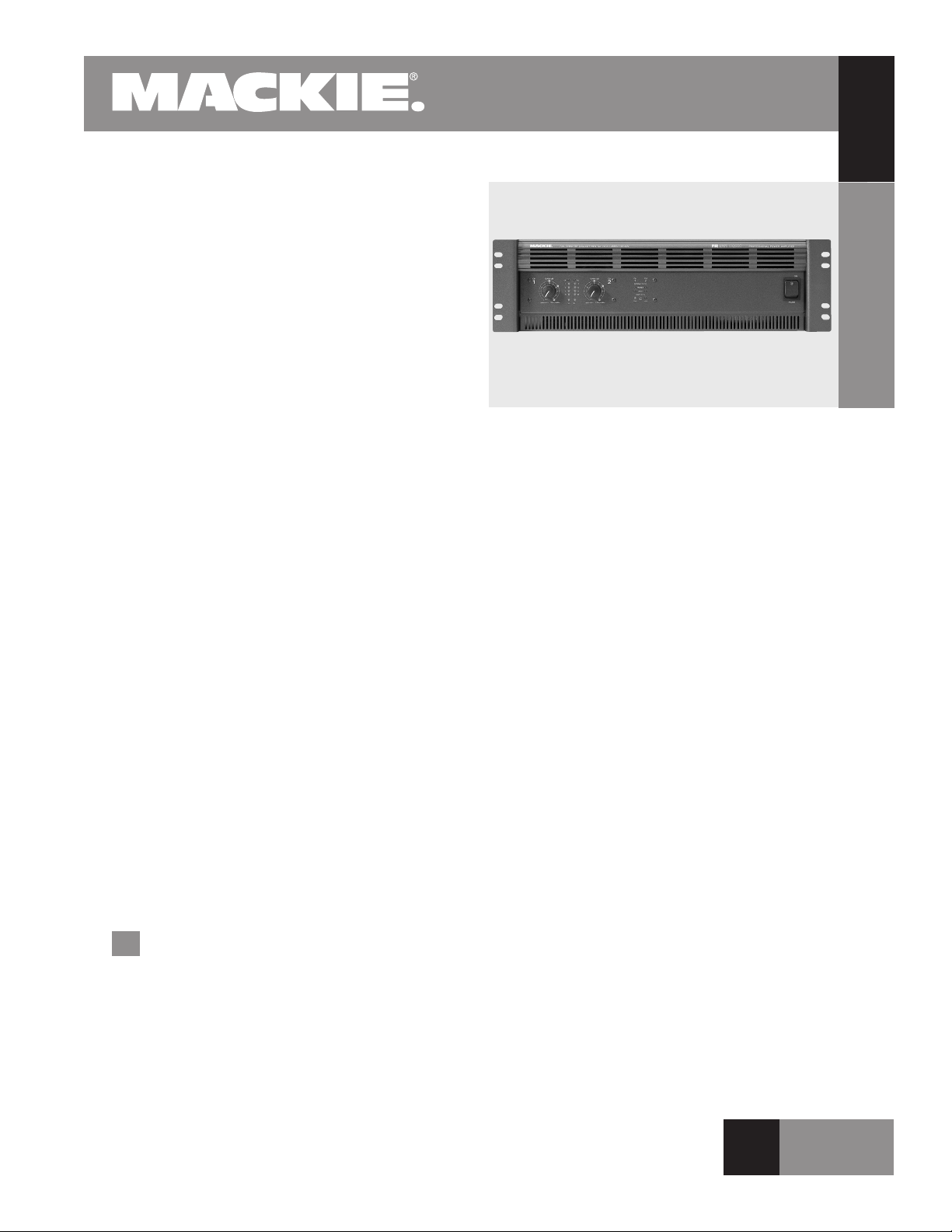
The Mackie Designs M•2600 is a dual channel,
high output power amplier that incorporates a
number of unique features including FR “Fast
Recovery” design, high continuous current output,
and a T-Design constant gradient cooling tunnel for
improved cooling efciency and output device reliability.
The M•2600 is rated at a continuous output of
425 watts per channel into 8Ω, 700 watts per channel into 4Ω and 1000 watts into 2Ω. In bridge mode
the M•800 is rated at 1400 watts into 8Ω and 2000
watts into 4Ω. Variable low-cut lters on each channel with a range from off to 170Hz enable tighter
bass response. The built-in limiter helps eliminate
clipping. Inputs are balanced/unbalanced 1/4" and
XLR, and XLR thru outputs are switchable to send
either the full-range signal, or the post-crossover
low-frequency or high-frequency output, to another
amplier. Speaker connections on the M•2600 are
1/4" and Speakon® connectors, with an additional
Speakon output for mono bridge operation. An amp
mode switch selects stereo, mono, or bridge operation.
To effectively deal with clipping, an amplier must
be able to recover almost instantaneously. That is the
denition of “Fast Recovery.” Rather than using negative feedback to help control clipping distortion, the
M•2600 employs a very sparse amount of negative
feedback. The use of Baker Clamp circuits on the positive and negative voltage amp stages prevents saturation (and latching) during periods of overdrive. In
addition, a transistor senses when the Baker Clamp
is active and activates the internal limiting circuits.
This results in no latching, instant recovery from overdriving the amp, and a superior sound.
(continued on page 3)
High-Current Power Amplier
Features
2600 watts max, 2000 watts continuous @ 4 ohms
bridged
Ultra-low-noise/low-distortion design
Fast Recovery circuitry reduces distortion at clipping
Two 2nd order, 12 dB/octave, Bessel low-cut lters
with variable frequency from Off to 170Hz
Two superior design 4th order Linkwitz-Riley active
crossovers (24 dB/octave)
Selectable crossover points of 60, 90, or 120Hz
Limiter with on/off switch
Balanced/unbalanced 1/4" and XLR inputs
XLR input loop-throughs, selectable for full-range,
high-pass, or low-pass output
Speakon® and 5-way binding post output connectors
Detented gain controls calibrated in dB and volts
Signal present and OL LEDs
Channel Status LEDs
Superior T-Design cooling
Five-year, limited warranty (U.S. only)
AMPLIFIER
M•2600
R E L A T E D P R O D U C T S
M•800/M•1400/M•1400i Power Ampliers,
1202-VLZ PRO 12-Channel Mic/Line Mixer, 1402-VLZ
PRO 14-Channel Mic/Line Mixer, 1604 VLZ PRO
16-Channel Mic/Line Mixer, 1642-VLZ PRO 16-Channel
Mic/Line Mixer, SR24•4-VLZ PRO 24 Channel Mic/Line
Mixer, SR32•4-VLZ PRO 32 Channel Mic/Line Mixer, CFX
Series 12, 16, and 20 Channel Mic/Line Mixer w/Digital
Effects, C300 2-Way Loudspeaker, S500 2-Way Loudspeaker, SWA1501 and SWA1801 Active Subwoofers.
Applications
Live sound/music reinforcement for churches,
clubs, schools, conference centers, hotels
High level A/V playback
Large speech systems
O F 6 P A G E S
1
o F 6 PA GE S
Page 2
M•2600
M•2600 Specications
AMPLIFIER
Maximum Power mid-band at 1% THD:
500 watts per channel into 8 ohms
850 watts per channel into 4 ohms
1300 watts per channel into 2 ohms
1700 watts into 8 ohms bridged mono
2600 watts into 4 ohms bridged mono
Continuous Sine Wave Average Output Power, both
channels driven (20Hz - 20kHz):
M•2600
425 watts per channel into 8 ohms <0.025% THD
700 watts per channel into 4 ohms <0.050% THD
1000 watts per channel into 2 ohms <0.1% THD
Bridged mono operation (20Hz - 20kHz):
1400 watts per channel into 8 ohms: <0.05% THD
2000 watts per channel into 4 ohms <0.1% THD
Power Bandwidth:
20Hz to 70kHz (+0, –3dB) @ 700 Watts into 4 ohms
Frequency Response:
20Hz to 40kHz (+0, –1dB)
10Hz to 70kHz (+0, –3dB)
Distortion:
THD, SMPTE IMD, TIM
<0.025%@8Ω
<0.050%@4Ω
<0.150%@2Ω
Signal to Noise Ratio
>107dB relative to rated power into 4 ohms
Channel Separation:
>80dB@1kHz
Damping Factor:
>350 from 0 to 400Hz
Input Impedance:
24kΩ balanced bridging
Input Sensitivity:
1.23 volts (+4 dBu) for rated power into 4 ohms
Gain:
32.7 dB (voltage gain of 43)
Maximum Input Level:
9.75 volts (+22 dBu)
Rise Time:
<5 µs
High-Current Power Amplier
Slew Rate:
Voltage Slew Rate >60V/µs
Current Slew Rate >30A/µs at 2Ω
CMRR:
>40 dB, 20Hz to 20kHz
Transient Recovery:
<1µs for 20dB overdrive at 1kHz
High-Frequency Overload and Latching:
No latch up to any frequency or level
Variable Low-Cut Filter:
10Hz (Off) to 170Hz, 2nd Order Bessel
Internal Crossover:
Switched 60Hz/90Hz/120Hz, 4th Order Linkwitz-Riley
Amplier input is low-pass ltered when switched to sub-
woofer mode
Low-pass and high-pass outputs switchable to thru output
jacks
Limiter Section:
Complementary Positive and Negative Peak Detecting
Indicators:
6 meter LEDs per channel
SIG (Signal Present), –20, –9, –6, –3, OL (Overload)
CH1 & 2
PROTECT LEDs
SHORT LEDs
TEMP STATUS
COLD/HOT LEDs
Power Consumption:
1650 watts (18.2A) with musical program fully loaded
(2Ω per side, or 4Ω bridged)
AC Line Power:
US 120 VAC, 60Hz
Europe 240 VAC, 50/60Hz
Japan 100 VAC, 50/60Hz
Korea 220 VAC, 60Hz
AC Drop-out Voltage:
At approximately 63% of rated line voltage
Physical:
Height: 5.20" (132mm)
Width: 19.00" (483 mm)
Depth: 15.65" (398 mm)
Overall Depth: 16.67" (423 mm)
Weight: 55 lbs (25 kg)
O F 6 P A G E S
2
o F 6 PA GE S
Page 3

M•2600
19.00" (483mm)
ventilation slots
(do not cover)
17.24" (438mm)
Depth 15.65" (398mm)
NOTE: The Depth is measured from the rear face of the rack ears
5.2"
(132mm)
3U
Overall Depth 16.67" (423mm)
CH
1
GAIN/dB
CH
2
CH
1
CH
2
ON
OF
F
POWER
GAIN/dB
PROFES SIONAL POWER AMPLIF IER
FULL SYMMETRY DUAL DIFFERENTIAL HIGH CURRENT DESIGN
High-Current Power Amplier
(continued from page 1)
The M•2600 uses a unique T-Design constant gradi-
ent cooling tunnel that draws air in through the front
of the amplier and forces it through the amplier’s
sides. The T-Tunnel design provides a shorter, more
direct path for cool air. This allows for reduced heat
build up and cooler transistor operation.
The amplier has a subwoofer mode that allows
you to turn on the built-in subwoofer crossover. When
activated, the signals appearing at the left and right
inputs are summed, directed to a low-pass lter, and
routed to both output stages. A switch selects the cutoff frequency of the lter at 60Hz, 90Hz, or 120Hz.
3
O F 6 P A G E S
o F 6 PA GE S
Page 4
M•2600
+
–
+
–
CH.1 100 VDC
+
–
CH.1 115 VDC
+
–
CH.2 115 VDC
TO
ROIDAL POWER
TRANSFORMER
LAMP
FUSE
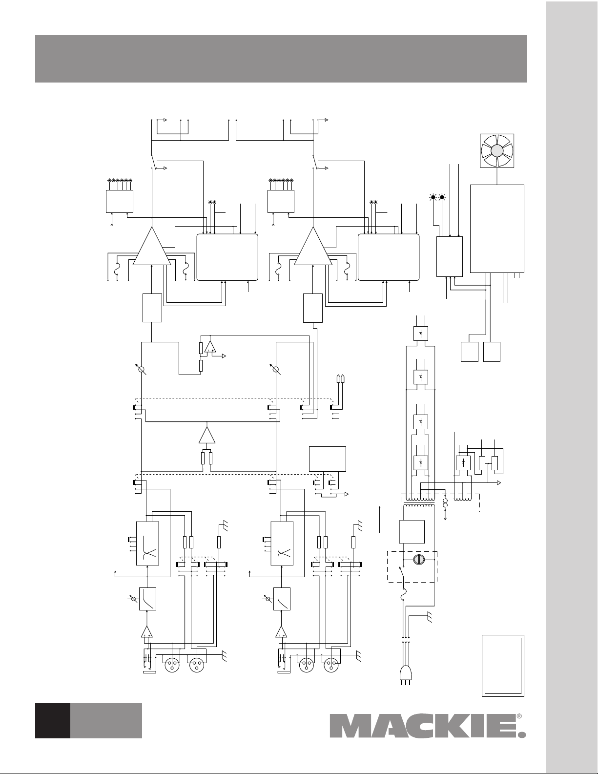
MACKIE DESIGNS
M•2600
BLOCK DIAGRAM
9/21/1998
LOW CUT
FILTER
CROSSOVER
INVERTER
(FOR BRIDGED MONO
OPERATION)
FREQ
CH.1 GAIN
CH.2 GAIN
60-90-120Hz
THRU–LOW–HIGH
LIMIT–OFF-LOW OUT
POWER
SWITCH
IN-RUSH
LIMIT
30 VDC
+15 VDC
-15 VDC
22 VA
C
+
–
CH.2 100 VDC
TRANSFORMER
THERMAL
LINE INPUT
(1/4" TRS)
LINE INPUT
(XLR-FEMALE)
THRU OUTPUT
(XLR-MALE)
STEREO-MONO-BRIDGED
STEREO-MONO-BRIDGED
STEREO-MONO-BRIDGED
LIMITER
CONTROL
CH–1
CH–2
LOW
HIGH
LOW CUT
FILTER
CROSSOVER
FREQ
SHORT
2
IN-RUSH CONTROL
THRU–LOW–HIGH
LIMIT–OFF-LOW OUT
LIMIT–OFF-LOW OUT
LINE INPUT
(1/4" TRS)
LINE INPUT
THRU OUTPUT
(XLR-MALE)
60-90-120Hz
LOW
HIGH
SHORT 1
(THE SHORT LEDS ARE
JOINED IN BRIDGED MODE)
LIMITER
CHANNEL 1
POWER
AMPLIFIER
FUSE
OUTPUT
RELA
Y
–100VDC
–115VDC
22VAC
FUSE
+100VDC
+15VDC
+15VDC
+115VDC
METER
DRIVE
OL
–3
–6
–9
–20
SIG
PROTECT
SHOR
T
SHORT
1
CH 1
SIG
CH
1
SIG
CH
2
SIG
CH.
1
SPEAKER
OUT
CH.
2
SPEAKER
OUT
CH.
1
SPEAKON
CH.
2
SPEAKON
BRIDGED
MONO
SPEAKON
PROTECTION CIRCUITRY
MUTE
DC OFFSET
PR
OTECT
SHORT
OUTPUT ST
AGE CURRENT
OUTPUT ST
AGE VOLTAGE
TRANSIENT SOA FL
T
STEADY STATE SOA FLT
OUTPUT DISSIP
ATION
LOW VOLTAGE DETECT
IN-RUSH CONTROL
CH.1 DISSIPATION
MUTE
LIMITER
CHANNEL 2
POWER
AMPLIFIER
FUSE
OUTPUT
RELA
Y
–100VDC
–115VDC
22VAC
FUSE
+100VDC
+15VDC
+15VDC
+115VDC
METER
DRIVE
OL
–3
–6
–9
–20
SIG
PROTECT
SHOR
T
CH 2
SIG
PROTECTION CIRCUITRY
MUTE
DC OFFSET
PR
OTECT
SHOR
T
OUTPUT ST
AGE CURRENT
OUTPUT STAGE VOLTAGE
TRANSIENT SOA FLT
STEADY STATE SOA FLT
OUTPUT DISSIPATION
LOW VOLTAGE DETECT
IN-RUSH CONTROL
CH.2 DISSIPATION
MUTE
+30VDC
-30VDC
HOT LED
COLD LED
CH.1 MUTE
CH.2 MUTE
80
0
C MUTE
52
0
C UN-MUTE
80
0
C MUTE
52
0
C UN-MUTE
CH 1
TEMP
SENSOR
CH 2
TEMP
SENSOR
OVER TEMPERATURE
DETECTOR
TRANSFORMER
THERMAL SWITCH
VARIABLE SPEED FAN CONTROLLER
45
0
C – 65
0
C SPEED CONTROL CH.1
45
0
C – 65
0
C SPEED CONTROL CH.2
FAN IDLE/VARIABLE CH.1 POWER DETECTOR
FAN IDLE/VARIABLE CH.2 POWER DETECTOR
CH.1 DISSIPATION
CH.2 DISSIP
ATION
FAN
Σ
1-
1+
1-
1+
-
+
-
+
1-
1+
SHORT 2
(THE CHANNELS ARE
SUMMED IN MONO
OR BRIDGED MODE)
M•2600
Block Diagram
High-Current Power Amplier
O F 6 P A G E S
4
o F 6 PA GE S
T R I M 3 / 4 ” O F F T H I S E D G E
Page 5

M•2600
OL
–3
–6
–9
–2
0
–3
–6
–9
–2
0
SIGOLSIG
CH
1
33
31
29
23
25
21
2719
17
11
33
31
29
23
25
21
2719
17
11
0
0
1.23v (+4dBu)
SENSITIVITY
GAIN/dB
CH
2
PROTECT
COLD HOT
SHORT
TEMP STATUS
INTERNAL STATUS
CH
1
CH
2
CH
1&2
POWER
3v
2v
1v
0
0
1.23v (+4dBu)
SENSITIVITY
GAIN/dB
3v
2v
1v
PROFE SSIONAL POWER AMPL IFIER
FULL SYMMETRY DUAL DIFFERENTIAL HIGH CURRENT DESIGN
SERIAL NUMBER
MANUFACTURING DATE
RISK OF ELECTRIC SHOCK
DO NOT OPEN
CA UTI ON
2600 WATTS
4 OHM LOAD MIN.
120 VAC 60 Hz
2000 WATT
S
STEREO
TYPICAL
CH
1
CH
2
MONO
BRIDGE
• THE FOLLOWING ARE REGISTERED TRADEMARKS OF MACKIE DESIGN INC.: "MACKIE", "FR SERIES", AND THE "RUNNING MAN" FIGURE •
CONCEIVED AND DESIGNED BY MACKIE DESIGNS INC • WOODINVILLE
WA • 98072 • USA • PATENTS PENDING • COPYRIGHT ©1998
1300 WATTS / CH
2 OHM LOAD MIN.
1
CHANNEL
MONO
BRIDGE
S
U
B
W
O
O
F
E
R
TYPICAL
35 Hz
CHANNEL
2
ON
TYPICAL
CAUTION
LETHAL VOLTAGES MAY APPEAR AT OUTPUT
TERMINALS. CLASS 1 WIRING IS REQUIRED
SPEAKER OUTPUTS
IN
IN
LOW CUT FILTER
INPUT
INPUT
CROSSOVER
SWITCHED OUTPUT
SWITCHED OUTPUT
BALANCED
OR
UNBALANCED
170 Hz
100 Hz
OFF
STAGE
MONITOR
90Hz
LOW
OUT
HIGH
OUT
THRU
LOW
OUT
HIGH
OUT
THRU
120Hz
60Hz
CROSSOVER
90Hz
120Hz
60Hz
AMP MODE
BRIDGED
MONO
OUTPUT APPLICATION
BALANCED
OR
UNBALANCED
LIMITER
(CH1 & CH2)
LOW OUT
(SUB WOOFER)
OFF
CH's
SUMMED
FULL
RANGE
LOW CUT FILTER
170 Hz
100 Hz
OFF
STAGE
MONITO
R
S
U
B
W
O
O
F
E
R
TYPICAL
35 Hz
WARNING:
TO REDUCE THE RISK OF FIRE OR ELECTRIC SHOCK, DO NOT
EXPOSE THIS EQUIPMENT TO RAIN OR MOISTURE. DO NOT REMOVE COVER.
NO USER SERVICEABLE PARTS INSIDE. REFER SERVICING TO
QUALIFIED PERSONNEL.
AVIS:
RISQUE DE CHOC ELECTRIQUE — NE PAS OUVRIR
PIN 1+CH1+
PIN 1
–
CH1
–
PIN 2+ & 2–NOT USED
PIN 1
+ CH2+
PIN 1
–
CH2
–
PIN 2+ & 2–NOT USED
PIN 1
+BRIDGE+
PIN 1
–
BRIDGE
–
PIN 2+ & 2–NOT USED
THRU
THRU
+
––
+
+
–
High-Current Power Amplier
T R I M 3 / 4 ” O F F T H I S E D G E
Architects’ and Engineers’ Specications
1. GENERAL. The amplier shall have a free-standing
frame with front and rear brackets for rack-mounting, and
supplied with four resilient feet suitable for table-top placement. The amplier shall be capable of two-channel operation, with a switch to place the amplier into single-channel
operation by bridging the outputs of the two channels.
2. POWER OUTPUT. The two-channel power amplier
shall deliver a rated continuous average sine wave power
output over a 20Hz to 20kHz bandwidth of 425 watts RMS
into 8 ohms per channel, 700 watts into 4 ohms, and 1000
watts into 2 ohms with both channels operating, with no
more than 0.05% total harmonic distortion. In single-channel
operation it shall deliver 1400 watts RMS into 8 ohms and
2000 watts into 4 ohms, with no more than 0.10% total harmonic distortion.
The power amplier shall deliver a maximum continuous
average sine wave power output at mid-band of 500 watts
RMS into 8 ohms per channel, 850 watts into 4 ohms, and
1300 watts into 2 ohms with both channels operating, with
no more than 1% total harmonic distortion. In single-channel
operation it shall deliver 1700 watts RMS into 8 ohms and
2600 watts into 4 ohms, with no more than 1% total harmonic
distortion.
5
O F 6 P A G E S
o F 6 PA GE S
3. POWER SUPPLIES. All necessary operating voltages for
the amplier shall be provided by an internal power supply. A
master power switch shall be located on the front panel along
with a green power-indicating light.
4. INPUT CHANNEL CONNECTIONS. Each monaural input
channel shall have an electronically balanced line-level input,
presenting no less than a 20k ohm impedance to the source.
Each input shall have an input sensitivity of +4 dBu, requiring
no more than 1.23V RMS to be driven to rated output into
a 4-ohm load. The input connector shall appear on the rear
panel as a female XLR-3 type connector. In addition, each
monaural input channel shall have a parallel 1/4" TRS phone
jack and a male XLR-3 type connector, which can be used
as inputs or “thru” jacks for daisy-chaining the input signal
to another amplier, or a high- or low-frequency crossover
output for subwoofer applications. Pin 2 of the XLR connectors, and the tip of the 1/4" TRS phone jack, shall be noninverting.
5. INPUT CHANNEL LEVEL CONTROLS. Each monaural
input channel shall be equipped with a gain control appearing
on the front panel, each having 20 detent positions, and calibrated in dB and volts.
6. FRONT PANEL INDICATORS. Each channel shall have
an associated six-segment LED meter appearing on
panel, capable of displaying signal present, –20 dB,
(continued on page 6)
the front
–9 dB,
Page 6

M•2600
(continued from page 5)
AMPLIFIER
–6 dB, –3 dB, and overload. Each channel shall have internal status LEDs appearing on the front panel to indicate
activation of protect mode and short-circuit protection.
Two temperature status LEDs shall appear on the front
panel, one to indicate normal operation (COLD) and one to
indicate thermal protection (HOT).
High-Current Power Amplier
7. PROTECTION FEATURES. The amplier shall pro-
vide delayed activation of the outputs at turn-on. Each
channel shall have a short-circuit protection circuit for
detecting excessive current ow at the output that, when
M•2600
activated, mutes the output for four seconds. The shortcircuit protection shall continuously cycle on and off until
the shorted condition is remedied. The amplier shall
have a thermal protection circuit to protect the power
devices from over-temperature operation. The circuit shall
activate when the internal temperature crosses the safeoperating threshold and, when activated, mute the outputs until the internal temperature cools to a safe-operating temperature, at which time amplier shall resume
normal operation. The amplier shall have a fan to cool
the heat-producing internal components, drawing cool air
in from the front, and exhausting warm air out through
both sides. The fan speed shall be variable, the speed
being determined by the internal temperature and the signal level present at the output. The amplier shall have
an SCR crowbar circuit to protect the speakers against a
catastrophic amplier failure. The circuit shall activate in
the presence of continuous DC at the speaker outputs,
and shall shut the amplier down by turning off the highvoltage rails.
8. OUTPUT CONNECTIONS. Each channel shall have
a heavy-duty 5-way binding post speaker output connector
appearing on the rear panel, with 3/4" spacing for accommodating standard double banana plugs as well as spade
lugs or bare wires. Each channel shall have a Neutrik
brand Speakon® output jack appearing on the rear panel
in parallel with the binding post. A separate Speakon®
connector shall be provided for the bridged mode mono
output.
9. AMP MODES. The amplier shall have a three-way
switch appearing on the rear panel for selecting the mode
of operation, which shall include stereo (two channels in,
two channels out), mono (one channel in, two channels
out), and bridge (one channel in, one channel out, bridged
between both speaker outputs).
10. OUTPUT APPLICATIONS. The amplier shall have
a three-way switch appearing on the rear panel for selecting between limiter on, limiter off, and subwoofer mode.
The defeatable electronic limiter circuit shall sense the
onset of clipping and shall limit the input signal and thereby prevent the output from clipping.
11. CROSSOVER. Each channel shall have a 4th order
Linkwitz-Riley, 24 dB/octave crossover with switch-selectable crossover frequencies of 60, 90, or 120Hz. When the
subwoofer mode is selected, the two input channels shall
be summed and the low-frequency output from the crossover shall be routed to the selected channel. In the fullrange modes, the high- or low-frequency output of the
crossover may be routed to the input thru connector via a
rear panel switch.
11. LOW-CUT FILTER. Each channel shall have a low-
cut lter with a variable frequency control appearing on
the rear panel covering a range of 10Hz (OFF) to 170Hz.
12. PHYSICAL CONFIGURATION. The amplier shall
be rack-mountable with rear support rails for extra support, and shall have a steel chassis frame painted grayblack. The amplier shall be 19" wide (483 mm), 5.2" (3U)
tall (132mm), and 16.67" deep (423 mm), and shall weigh
55 pounds (25 kg).
13. DESIGNATION. The power amplier shall be a
Mackie Designs M•2600.
Electronic les for this product available at:
www.mackie.com
This Specication Sheet M2600_SS.PDF
Owner/Operator’s Manual M2600_OM.PDF
CADD les M2600.DXF
Mackie Designs Inc. continually engages in research related to product improvement. New material,
production methods, and design renements are introduced into existing products without notice as a
routine expression of that philosophy. For this reason, any current Mackie Designs product may differ
in some respect from its published description, but will always equal or exceed the original design
www.mackie.com
specications unless otherwise stated. ©1999-2002 Mackie Designs Inc. All rights Reserved. Mackie and
the “Running Man” gure are registered trademarks of Mackie Designs Inc.
16220 Wood-Red Road NE, Woodinville, WA 98072 USA
888.337.7404, fax 425.487.4337, sales@mackie.com
UK +44.1268.571.212, fax +44.1268.570.809, uk@mackie.com
ITALY +39.0522.354.111, fax +39.0522.926.208, italy@mackie.com
FRANCE +33.3.85.46.91.60, fax +33.3.85.46.91.61, france@mackie.com
GERMANY +49.2572.96042.0, fax +49.2572.96042.10, germany@mackie.com
Part No. 091-211-00 Rev. A 6/02
O F 6 P A G E S
6
o F 6 PA GE S
 Loading...