

Page 1

Logic 7
Dedicated Control Surface Support
Page 2

Apple Computer, Inc.
© 2004 Apple Computer, Inc. All rights reserved.
Under the copyright laws, this manual may not be
copied, in whole or in part, without the written consent
of Apple. Your rights to the software are governed by
the accompanying software licence agreement.
The Apple logo is a trademark of Apple Computer, Inc.,
registered in the U.S. and other countries. Use of the
“keyboard” Apple logo (Option-Shift-K) for commercial
purposes without the prior written consent of Apple
may constitute trademark infringement and unfair
competition in violation of federal and state laws.
Every effort has been made to ensure that the
information in this manual is accurate. Apple Computer,
Inc. is not responsible for printing or clerical errors.
Apple Computer, Inc.
1 Infinite Loop
Cupertino, CA 95014-2084
408-996-1010
www.apple.com
Apple, the Apple logo, Aqua, Final Cut, Final Cut Pro,
FireWire, iBook, iMac, iPod, iTunes, Logic, Mac,
Macintosh, Mac OS, PowerBook, Power Mac, Power
Macintosh, and QuickTime are trademarks of Apple
Computer, Inc., registered in the U.S. and other
countries.
Finder and GarageBand are trademarks of Apple
Computer, Inc.
AppleCare is a service mark of Apple Computer, Inc.
Helvetica is a registered trademark of Heidelberger
Druckmaschinen AG, available from Linotype Library
GmbH.
Other company and product names mentioned herein
are trademarks of their respective companies. Mention
of third-party products is for informational purposes
only and constitutes neither an endorsement nor a
recommendation. Apple assumes no responsibility with
regard to the performance or use of these products.
Page 3

1
Contents
Preface 7 What Is Covered
7 CM Automation Motormix 7 CM Labs Motormix 7 Emagic Logic Control 8 Emagic Logic Control XT 8 Mackie Baby HUI 8 Mackie C4 8 Mackie Control 8 Mackie Control Extender 9 Mackie Control Universal 9 Mackie HUI 9 Radikal Technologies SAC-2.2 9 Radikal Technologies SAC-2k 9 Roland SI-24 9 Tascam FE-8
9 Tascam FW-1884 10 Tascam US-224 10 Tascam US-428 10 Yamaha 01V96 10 Yamaha 02R96 10 Yamaha 01X 10 Yamaha DM1000
11 Yamaha DM2000
Chapter 1 13 Logic Control—Basics
13 Introduction 14 Getting Started 17 View Modes 21 The Displays 23 About Alert Messages
24 Tips
3
Page 4

Chapter 2 27 Logic Control—Details
28 The Channel Strip(s)
31 The Assignment Zone
46 Fader Bank Zone 48 Master Fader 49 Display Zone
51 The Function Key Zone
52 The Global View Zone 52 Function Button Zone 56 The Transport Zone 64 The Cursor/Zoom Key Zone 65 The Jog/Scrub Wheel Zone 65 Functions and Menus
Chapter 3 75 Mackie C4
75 V-POTs, V-SELECTs 78 Buttons at Bottom 80 Marker Overlay 80 Track Overlay 80 Channel Strip Overlay 81 Function Overlay 83 Assignment Overview
Chapter 4 85 Tascam FW-1884
85 Introduction 85 Requirements 85 Set Up 85 Operation 86 Assignment Overview
Chapter 5 91 Mackie HUI
91 Requirements 91 Set Up 91 Other HUI-compatible Devices 92 Assignment Overview
Chapter 6 103 Mackie Baby HUI
103 Requirements 103 Assignment Overview
Chapter 7 107 Yamaha DM2000
107 Requirements 107 Set Up 108 Assignment Overview
4
Contents
Page 5

Chapter 8 117 Yamaha DM1000
117 Requirements 117 Set Up 118 Assignment Overview
Chapter 9 125 Yamaha 02R96
125 Requirements 125 Set Up 126 Assignment Overview
Chapter 10 131 Yamaha 01V96
131 Requirements 131 Set Up
132 Assignment Overview 135 Selected Channel 135 Data Entry Section 135 Channel Strips 135 Stereo Channel Strip 136 USER DEFINED KEYS Section
Chapter 11 139 CM Labs Motormix
139 Requirements 139 Set Up 139 Assignment Overview
Chapter 12 147 Radikal Technologies SAC-2K
147 Requirements 147 Set Up 147 Assignment Overview
153 Troubleshooting
Chapter 13 155 Roland SI-24
155 Requirements
155 Set Up
155 Assignment Overview
Chapter 14 161 Tascam US-428
161 Requirements
161 Assignment Overview
Appendix A 165 Logic Control—Specifications
165 Logic Control (Base Unit) 167 Logic Control XT (Extension Unit)
Contents
5
Page 6

Appendix B 169 Logic Control—MIDI Implementation
169 SysEx Message Header 170 Global Control Messages 172 Common Control Messages
Appendix C 181 Logic Control—Control Surface Layout and IDs
Appendix D 185 Logic Control—MIDI Implementation Chart
Index 187
6
Contents
Page 7

What Is Covered
This manual covers Logic’s dedicated control surface
support. Please read it thoroughly to make the most of
your new controller(s).
Logic comes with dedicated support for certain control surface models. There are
several plug-ins which are are a part of Logic. Some plug-ins support multiple similar
control surface models.
You can use any combination of control surfaces with Logic. However you get the most
out of them when using them in a Control Surface Group if they are all supported by
the same plug-in.
Here you find an alphabetic list of the supported control surfaces, how they differ from
similar devices and a cross reference to the relevant sections.
Preface
CM Automation Motormix
Only available in Logic Pro, not in Logic Express.
See section “CM Labs Motormix” on page 133.
CM Labs Motormix
Only available in Logic Pro, not in Logic Express.
See section “CM Labs Motormix” on page 133.
Emagic Logic Control
If you have installed Mackie’s firmware version 1.0.2 or higher, make sure that the Logic
Control runs in Logic Control mode. See sections “Logic Control—Basics” on page 13
and “Logic Control—Details” on page 26.
Also see the Appendix for more details.
7
Page 8

Emagic Logic Control XT
This is the extension unit for the Logic Control. It has only the channel strip section;
therefore it is not useful without a Logic Control.
If you have installed Mackie’s firmware version 1.0.2 or higher, make sure that the Logic
Control XT runs in Logic Control mode.
See sections “Logic Control—Basics” on page 13 and “Logic Control—Details” on
page 26.
Also see the Appendix for more details.
Mackie Baby HUI
Only available in Logic Pro, not in Logic Express.
The Baby HUI is a stripped-down version of the HUI. For easier navigation, we have
documented it in a separate section.
See section “Mackie Baby HUI” on page 98.
Mackie C4
The Logic Control plug-in has been extended for dedicated support for the Mackie C4.
Please see section “Mackie C4” on page 73.
Mackie Control
The original Mackie Control is similar to the Logic Control in hardware, however the silk
screening is different. You should request a Logic Control Lexan Overlay from Mackie to
get the correct silk screening. See
http://www.mackie.com/products/mackiecontrol/mackiecontrol_overlay.html
Firmware version 1.0.2 or higher is required, and it must be switched to Logic Control
mode.
See sections “Logic Control—Basics” on page 13 and “Logic Control—Details” on
page 26.
Mackie Control Extender
Firmware version 1.0.2 or higher is required, and it must be switched to Logic Control
mode. See the documentation from Mackie on how to switch to Logic Control mode.
See sections “Logic Control—Basics” on page 13 and “Logic Control—Details” on
page 26.
8 Preface
What Is Covered
Page 9

Mackie Control Universal
The Mackie Control Universal must be switched to Logic Control mode. See the
documentation from Mackie on how to switch to Logic Control mode.
See sections “Logic Control—Basics” on page 13 and “Logic Control—Details” on
page 26.
Mackie HUI
Only available in Logic Pro, not in Logic Express.
The HUI plug-in has been tested with the original Mackie HUI. There are other control
surfaces not mentioned here which can emulate the HUI, however we haven’t tested
this and don’t support them.
See section “Mackie HUI” on page 87.
Radikal Technologies SAC-2.2
Only available in Logic Pro, not in Logic Express.
There is a dedicated plug-in for the SAC-2.2/2k’s native mode.
The Logic Control plug-in detects an SAC-2.2 reacting in Logic Control emulation and
ignores it, to avoid that the SAC-2.2 is installed twice.
See section “Radikal Technologies SAC-2K” on page 140.
Radikal Technologies SAC-2k
See section “Radikal Technologies SAC-2K” on page 140.
Roland SI-24
See section “Roland SI-24” on page 146.
Tascam FE-8
Extension unit for FW-1884.
See section “Tascam FW-1884” on page 82.
Tascam FW-1884
See section “Tascam FW-1884” on page 82.
Preface
What Is Covered
9
Page 10

Tascam US-224
A stripped-down version of the US-428, with dedicated support in the US-428 plug-in.
See section “Tascam US-428” on page 151.
Tascam US-428
See section “Tascam US-428” on page 151.
Yamaha 01V96
Only available in Logic Pro, not in Logic Express.
The Yamaha 01V96 emulates two HUI units, using two virtual MIDI In and Out
connections over its USB cable.
See section “Yamaha 01V96” on page 125.
Yamaha 02R96
Only available in Logic Pro, not in Logic Express.
The Yamaha 02R96 emulates three HUI units, using three virtual MIDI In and Out
connections over its USB cable.
See section “Yamaha 02R96” on page 119.
Yamaha 01X
The Yamaha 01X emulates a Logic Control, however it does not have all of its controls.
Please refer to the 01X documentation for details.
Logic recognizes the 01X as such and shows a custom icon, however the remaining
communication is as with a Logic Control.
See sections “Logic Control—Basics” on page 13 and “Logic Control—Details” on
page 26.
Yamaha DM1000
Only available in Logic Pro, not in Logic Express.
The Yamaha DM1000 emulates two HUI units, using two virtual MIDI In and Out
connections over its USB cable.
See section “Yamaha DM1000” on page 111.
10 Preface
What Is Covered
Page 11

Yamaha DM2000
Only available in Logic Pro, not in Logic Express.
The Yamaha DM2000 emulates three HUI units, using three virtual MIDI In and Out
connections over its USB cable.
See section “Yamaha DM2000” on page 101.
Preface
What Is Covered
11
Page 12

Page 13

1
Logic Control—Basics
1
Introduction
Using a mouse and computer keyboard to do things normally done on an analog mixer
can be disconcerting. Clicking an onscreen fader or knob, and dragging the mouse to
achieve a silky smooth fade or pan move is difficult, if not impossible, for many users.
Logic Control provides you with hands-on control of virtually all of Logic’s real-time
parameters. Move a fader and Logic’s on-screen fader will move with it. Similarly, when
you make a fader move on-screen, the Logic Control fader moves. Adjust EQ by turning
one of Logic Control’s
take multiple mouse-clicks and/or key presses can now be achieved with the push of a
button, the turn of a knob or a quick fader movement.
You can use Logic Control to:
control all transport functions
•
•
adjust MIDI, audio instrument, bus, master and audio channel volume and pan levels
control channel EQ parameters
•
•
select and control all effect and audio instrument parameters
select, solo, mute and arm tracks
•
•
set and adjust send parameters
remotely switch between screensets
•
•
scrub MIDI and audio
•
zoom in on individual tracks
create, delete and move between markers, and much more.
•
V-POT
knobs and Logic will update instantly. In fact, what used to
The Logic Control XT expands on the number of tracks, parameters etc. that can be
controlled with individual faders, knobs and switches. The XT units are basically
identical to the channel strip section (fader,
You may add as many XT units as you wish to your Logic system, provided enough
MIDI in and out ports are available.
V-POT,
and LCD) of the Logic Control unit.
13
Page 14

All of your fader and
moves can be recorded and will faithfully play back in real-
V-POT
time. As the Logic Control units are equipped with motorized faders, remote controlled
buttons, knobs and LEDs, your automation data will be reflected on the Logic Control’s
surface instantly. This keeps you completely informed about all levels—for tracks, pan,
parameters, EQs etc.
The feedback you receive on the 2 row, by 55 character LCD is so good, in fact, that you
may find you rarely look at your computer monitor. This facility may also be particularly
useful in situations where computer fan noise is an issue; a common problem for
project studios not equipped with a vocal booth. This allows you to isolate, and
remotely control, your Logic system while singing or performing acoustically in another
room.
For live use, the Logic Control units are ideal. The performing musician now need only
take a laptop, equipped with suitable audio and MIDI interfaces (Emagic EMI 2|6 and
MT4, for example), a keyboard and a Logic Control to a live event. The backlit LCD is
ideal for darkened stage use. The largely metal construction, Penny and Giles™ faders
and solid buttons and switches are built to withstand the rigors of touring.
Given that Logic’s Track Automation facilities can be active, even when not in record
mode, you can capture your “live” realtime changes for later recall. This ensures that
you’ll never again lose that “once-in-a-lifetime” performance—on stage or in the studio.
We have every confidence that the Logic Control system will provide you with many
years of inspiration, fun, reliability and productivity.
Your Logic media production environment will never be the same!
Getting Started
To make use of the Logic Control unit, you will require:
•
an installed copy of Logic Pro7 or Logic Express 7
a free MIDI in
•
suitable MIDI interface, e. g. if using a Unitor 8 or AMT 8, which feature 8 MIDI in and
8 MIDI out ports, with one Logic Control and one Logic Control XT, you will need to
use 2 of the Unitor8/AMT8’s MIDI ins and 2 of its MIDI outs.
A “suitable” MIDI interface features drivers which support SysEx communication. Please
consult the documentation that shipped with your MIDI interface.
The number of units which can be run simultaneously is dependent on the availability
of free MIDI in and out ports in your MIDI system. In a “standard” setup, a single Logic
Control unit will be used alone, or accompanied by one or more Logic Control XT units.
It is also possible to make use of several Logic Control and several XT units to create
Control Surface Groups
14 Chapter 1
and
out port for
, as discussed in the Logic Reference Manual.
Logic Control—Basics
each
Logic Control or Logic Control XT unit, on any
Page 15
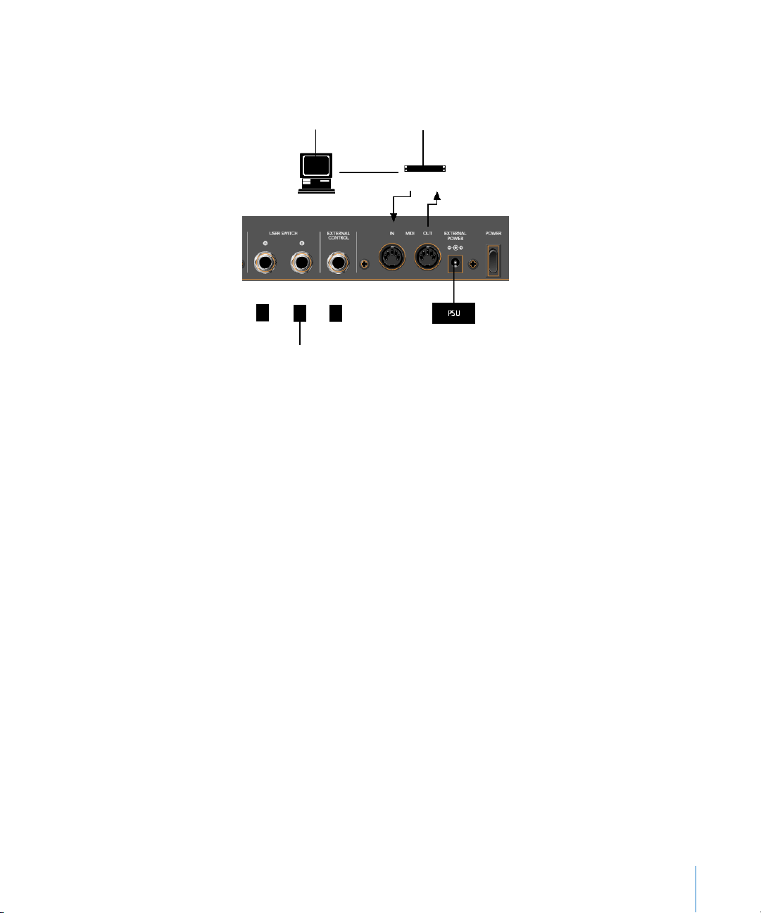
Connecting the Unit(s)
Connect your Logic Control and/or Logic Control XT units as shown in the diagram
below.
Computer
Optional Footswitches
As mentioned above,
MIDI in
and
MIDI out connection. Do
each
Logic Control or Logic Control XT unit must have a discrete
MIDI Interface
not
“daisy-chain” other MIDI devices via MIDI THRU
to the MIDI in or out ports used by the Logic Control units as this may result in data
errors.
About the Power Supply Unit (PSU)
The PSU which came with your Logic Control unit is rated at 7.5V, 4.0 Amps, with a
positive tip. Do not use any other power supply with the Logic Control units as this
may result in permanent damage. Any attempt to use another power supply with
either unit will automatically void your warranty.
Should you have a problem with the power supply unit, immediately disconnect it
from the Logic Control and wall socket to avoid damage or electrical shock. There are
no user-serviceable parts in the power supply unit (or the Logic Control units). If you
have a problem with your Logic Control or power supply unit, please contact the local
Emagic distributor in your region or territory.
Optional Footswitches and pedals
You may use optional foot switches to remotely control the start/stop and other
functions of the Logic Control. This may be useful for guitarists or other two-handed
playing. The foot switch sockets can use momentary foot pedals with either a positive
or negative polarity. By default:
•
USER SWITCH A
•
USER SWITCH B
is assigned to
is assigned to
Start/Stop
Record
.
(note that a track must be selected and armed
for recording to take place),
Chapter 1
Logic Control—Basics
15
Page 16

•
EXTERNAL CONTROL
is assigned to the
fader level. Only use an expression
MASTER
pedal with this socket.
The polarity of the foot switches is determined by the Logic Control when powered up.
Therefore it is useful to first connect the foot switches, then power up.
Power Up
Once everything is connected, press the power switch found to the rear left of your
Logic Control and Logic Control XT units. Once powered, the displays will illuminate
and the LCD will display a welcome message. Of note is the firmware version number
found in the bottom right hand corner of the display. Each fader will slide to the top,
and back to the bottom, of its travel. This self-diagnostic power-on procedure indicates
that your Logic Control units are functioning correctly.
Your computer and MIDI interface can be powered up before or after the Logic Control
units. Logic can be launched either before or after the units have completed
initialization.
About Software and Firmware
The Logic Control and Logic Control XT units have no “intelligence” of their own. Their
functionality is host software-based, making them
them what to do/how to behave. What this means is that the Logic Control cannot
perform any function that Logic itself cannot do. It also means that if Logic is not
booted, the Logic Control units will do nothing at all.
completely
reliant on Logic to tell
The plus side of this approach is that the units represent the ultimate in upgradable
hardware. As new functions are added to Logic, Logic Control will also be able to
access and control them.
The Logic Control units do, however, have a form of software called “firmware”. This
firmware is much like the BIOS found in your computer. New “behaviors”—at a
hardware level—such as an improved control of the fader servo motors and changes to
the display can be made via firmware updates.
The firmware is stored on an EEPROM (Electronically Erasable Programmable Read Only
Memory) chip. It can be updated via a simple MIDI dump procedure, in the form of a
MIDI file.
Should new firmware become available, you can simply download the appropriate
MIDI file and play it to your Logic Control unit(s), which will be updated accordingly.
The steps required to perform a firmware update will be outlined in the readme file
which accompanies the file. Please read this
16 Chapter 1
Logic Control—Basics
before
attempting any update.
Page 17

Quick Start
Once Logic is launched, any connected (and powered) Logic Control units will
automatically be detected. The LCD above the
from left to right) as they appear—from top to bottom—in the Arrange window Track
List of your Autoload song. The two character
Time Display
will display
1 1 1 1
, assuming that your Autoload song starts at this
position.
Please note that if running multiple units, the order of channels/tracks (from left to
right) needs to be defined. The easiest way to do this is to launch Logic, and then
switch on the units from left to right, with a delay of about 5 seconds between
powering up each unit. This only needs to be done once—and the setup will
automatically be created in the right order. Once the setup is defined, the order in
which you power up Logic or the Logic Control units doesn’t matter.
s will indicate the tracks (shown
V-POT
Mode Display
will display Pn, the
Position/
Should your Autoload song have the
Cycle
mode enabled or
muted
objects etc., the
corresponding LEDs on the Logic Control will be illuminated to reflect each track’s
current status.
It should be noted that the default settings and displays indicated above may be
slightly different on your unit. The reasons for any such differences include: Firmware
changes, software changes and user changes.
If the auto-detection phase completed correctly, you’re ready to go! If not, see the
Logic user manual for setup information.
Although the Logic Control is intuitive to use, the following sections will provide you
with information on accessing parameters and functions that may not be apparent at
first glance. Feel free to use them as a reference manual while experimenting.
View Modes
Before taking a look at the front panel of the Logic Control, we’d like to cover a
simple—but very important—concept.
Logic Control works in three discrete
•
Mixer View
Global View
•
•
Arrange View
—layout like in the Track Mixer window (
—layout like in the Track Mixer window (
—layout like in the Arrangement window.
View
modes.
Global
Global
switch off).
switch on).
These modes are mutually exclusive, so if you’re in one
the other.
It is important to note that the
Surface Group
, not a global setting. So one group can display the busses, while the
Mixer
vs.
Global View
modes is a property of the
other shows tracks, for example.
Chapter 1
Logic Control—Basics
View
mode, you cannot be in
Control
17
Page 18

Switching View Modes
To toggle between
button, located directly above the MASTER fader on the Logic Control.
Global View mode is indicated by the green LED to the right of the button. When
deactivated, the Logic Control will instantly switch to Mixer View mode.
All faders, V-POTs, switches, LEDs and LCDs will update to reflect the current View mode.
All settings of the Track and Global View modes are retained, so you can freely toggle
between the two modes, and pick up from where you left off.
However if one of the Channel Strip View modes was active, the Logic Control switches
back to the corresponding Multi Channel View mode, as you most probably first want to
select a different track.
Mixer
and
Global View modes, repeatedly press the GLOBAL VIEW
Mixer View
Mixer View is the default mode of the Logic Control.
Mixer View is simply the view of all tracks, as they appear in the Arrange window’s Track
List, e. g.—Track 1 = Channel 1 on the Logic Control, Track 2 = Channel 2, a. s. o.
It should be noted that if multiple tracks “point” to the same underlying object, then
only the first track will be displayed. If you want to see all of them, select Arrange View.
It does not matter if the tracks point to MIDI, Audio (this includes Buses etc.) or Audio
Instrument objects, which exist in the Environment of the song. This allows you to
make use of the Logic Control faders and V-POTs for any control task in Logic. This also
extends to Volume, Pan, Mute and Solo control of external MIDI devices, as well as the
parameters of the internal audio engine.
Global View
Global View limits the display to all Environment objects of a particular “class”, even if no
corresponding tracks exist in the Arrange window. As an example, in an Environment
that contains:
• 5 multi-timbral (16-channel) MIDI devices (i. e. 5 multi instrument objects)
• 64 Audio Tracks
• 16 Audio Instrument tracks
• 8 Buses
• 8 Inputs
• 8 Outputs
18 Chapter 1
Logic Control—Basics
Page 19
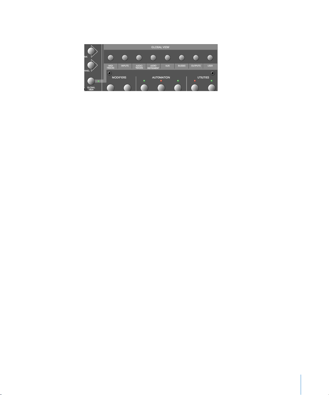
Global View gives you direct access to the Volume, Pan, Mute and Solo parameters of all
80 MIDI channels, 64 audio tracks etc. as outlined above.
Note the light gray legend which links the
GLOBAL VIEW button to the eight buttons in
the “Global View” zone of the Logic Control front panel.
Simply press the button which corresponds to the object “class” that you wish to view.
You can select multiple classes by clicking on multiple buttons simultaneously.
The OUTPUTS button activates both output and master objects.
The USER button is reserved for future Logic features.
The Track Mixer window’s contents automatically follows the
GLOBAL VIEW button’s
state and also sets the object filters according to the object classes activated in Global
View. You can disable this behavior with menu item View > Follow Control Surface.
Arrange View
Arrange View is similar to Mixer View, with one exception: Namely, if multiple tracks play
back via the same environment object, all of them will be displayed on separate
channel strips. This is helpful when used in conjunction with the nudge commands, for
example.
Arrange View is engaged by pressing the SHIFT and GLOBAL VIEW buttons
simultaneously. It is active as long as the GLOBAL VIEW button’s LED is blinking.
Folders
In Mixer View and Arrange View, Logic Control always displays the track of a certain
folder—by default those of the “root” folder, i. e. the top level folder.
Folder tracks use the instrument “Folder” which has no parameters at all. Therefore the
V-SELECT is available for other purposes than setting track parameters. Pressing the V-
SELECT
of a folder track enters the folder.
Alternatively you can select the folder track with
ENTER button.
You can leave a folder and return to the folder level above with the
Chapter 1 Logic Control—Basics 19
SELECT and enter the folder with the
CANCEL button.
Page 20

The following topics cover a couple of “viewing” options that work in all View modes.
Channel Views
The channels section (i. e. the channel strips) can be in two fundamental view
“modes”—Multi Channel and Channel Strip View. Normally, switching between these
modes only affects the V-POTs, with the other channel controls always remaining in
Multi Channel View.
Please note that there are some exceptions to this: in special view modes, the faders
and SOLO and MUTE buttons have alternate uses/meanings.
• Multi Channel View—shows one parameter for eight tracks (normally a section of the
Track Mixer window). If your Control Surface Group consists of a Logic Control and
additional Logic Control XTs, you will see more than eight tracks. The section can be
shifted to the next/previous group of channels with the FADER BANK buttons.
Please note that when in Multi Channel view: the display will automatically update
when another FADER BANK is selected. Please read the Fader Bank Zone section on
page 46.
• Channel Strip View—shows eight (or more) parameters of the selected track. The
display will automatically update when another track is selected.
Switching between Multi Channel and Channel Strip views is achieved by pressing the
ASSIGNMENT button whose LED flashes.
When pressing an ASSIGNMENT button which is not currently selected, the assignment
mode changes, and the according Multi Channel View is activated. Exception: switching
between Instrument Edit View and Plug-in Edit View.
Pages
Logic features the Channel EQ with 8 (Logic Pro) or 4 (Logic Express) bands per audio
channel. Each EQ has four (4) parameters. It also offers (up to) 16 Buses. Many of Logic’s
plug-ins—effects and Audio Instruments—plus those of third-party manufacturers,
feature dozens of parameters.
Every one of these parameters can be accessed by the Logic Control.
To give you an example of how this works, imagine a plug-in that contains, say, 16
parameters and you are using a single Logic Control.
Once you’ve switched to the appropriate “Channel Strip Edit View” of the plug-in you
wish to adjust, you can directly affect parameters 1 to 8 by using V-POTs 1 to 8. You can
then switch by a “page” to access parameters 9 to 16.
20 Chapter 1 Logic Control—Basics
Page 21
Simply press the LEFT/RIGHT CURSOR keys to step up/down to the next “page” of
parameters.
The current/total number of pages (e. g. “Page 1/3”) is displayed in the top right-hand
corner of the LCD whenever multiple “pages” are available—i. e. when parameter
names are shown in the lower row.
To get to the first or last page, hold down OPTION while pressing the LEFT/RIGHT
CURSOR key.
Switching by page is just the default. To switch by a single parameter, hold down C/
ALT while pressing the appropriate cursor key.
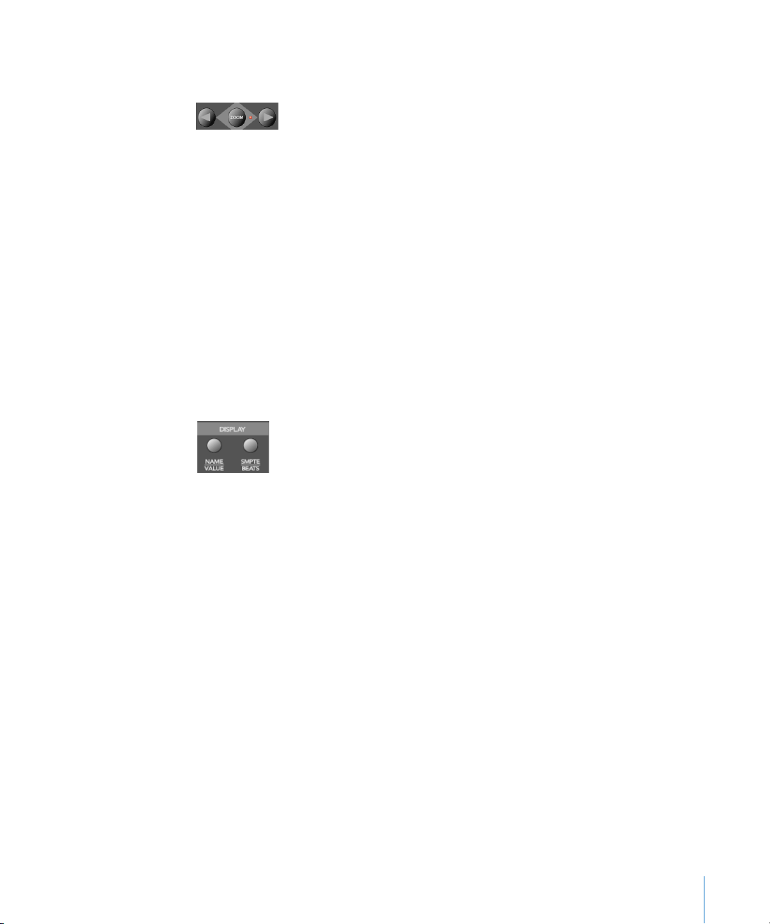
Viewing by Name or Value
As a personal preference, or for practical reasons, you may wish to view parameters by
their name, or by value. To toggle between the two Display formats—Name or Value—
repeatedly press the NAME/VALUE button in the Display section of the Logic Control—
just below the SMPTE/BEATS LEDs.
It should be noted that the NAME/VALUE button has a significant impact on the Multi
Channel and Channel Strip views of the various Assignment modes. The use of the
NAME/VALUE button in these view modes is covered throughout The Assignment Zone
section, from page 31 onwards.
The Displays
Liquid Crystal Display (LCD)
The LCD is a 2 row × 55 character backlit display.
Below the display, you will see eight (8) “notched” areas which act as visual cues,
making the separation of channels/parameters easier. These are numbered 1—8.
Short names
Each channel/parameter can be indicated by a name or value, up to 6 characters long,
dependent on the currently selected Display mode. In general, the upper row of each
channel/parameter will display the track name, and the lower row will display the
parameter name and/or value.
Chapter 1 Logic Control—Basics 21
Page 22

Note: 8-bit ASCII characters such as curly quotes and umlaut characters are replaced by
the best-possible 7-bit ASCII equivalent, e. g. ä = ae, ö=oe, ü=ue, á = a, ø = oe, œ = oe,
ß = ss, å = a.
In case you don’t like the way a track or instrument name is abbreviated, you can
provide your own version, simply by appending it with a backslash (\). To get the track
“My very long track name” displayed as “long” instead of “TrckNm”, the track name must
be “My very long track name\long”.
Long names
In some modes, a long (i. e. full) parameter or other name will be displayed briefly on-
screen, when adjusted. The display of long names, and the duration of this display, is
set in the Preferences. These settings are discussed in the Logic user manual.
Name vs. Value
To toggle between the two Display formats—Name or Value—repeatedly press the
NAME/VALUE button in the Display section of the Logic Control—just below the SMPTE/
BEATS LEDs.
The following is a brief overview of the effect the NAME/VALUE button has on the
various display modes.
• Multi Channel view, display mode Names: upper line shows track names, lower line
shows parameter names
• Multi Channel view, display mode Values: upper line shows track names, lower line
shows parameter values
• Channel Strip view, display mode Names: upper line shows view info, lower line shows
parameter names
• Channel Strip view, display mode Values: upper line shows parameter names, lower
line shows parameter values
Assignment LED (Mode Display)
To the right of the LCD, you will find the two digit, seven-segment LED display which
indicates the current Assignment status of the Logic Control. Throughout the manual
we refer to this LED as the Mode Display.
The Assignment status is determined by the 6 buttons found in the light gray
Assignment area directly below the Mode Display. We will discuss the use of these
buttons, and the abbreviations shown in the LED, in The Assignment Zone section, from
page 31 onwards.
Basically the display ends with a period whenever a Channel Strip View is active.
22 Chapter 1 Logic Control—Basics
Page 23

Song Position/SMPTE Time Display
The right-most display is a multi-digit, seven-segment LED. It is accompanied by two
small LEDs to its immediate left, which provide a quick visual indication of the currently
active display format: SMPTE or BEATS.
To toggle between the two Time formats, repeatedly press the SMPTE/BEATS button in
the Display section at the top of the Logic Control—just below the SMPTE/BEATS LEDs.
When BEATS mode is selected, the Position/Time Display is divided into 4 segments,
separated as follows:
Bars/Beats/Sub Divisions/Ticks
When SMPTE mode is selected, the Position/Time Display is divided into 4 segments,
separated as follows:
Hours/Minutes/Seconds/Frames
The display format can be viewed in a number of ways. This can be altered in Logic’s
Display Preferences.
Rude Solo LED
This LED indicates that either: an audio track is set to solo, or the track solo mode is
enabled. It is a helpful visual aid in situations where a track has been soloed and the
fader bank has been shifted—i. e. the soloed track’s Solo LED is no longer visible.
About Alert Messages
Alert messages are simply dialog or message boxes in Logic. As examples, file save
dialogs, authorization warnings, edit confirmations or error messages.
When these windows “pop up” on-screen, the Logic Control will respond in the
following way:
• all LEDs are deactivated,
• the upper LCD row shows the beginning of the alert text
Note: 8-bit ASCII characters such as curly quotes and umlaut characters are replaced by
the best-possible 7-bit ASCII equivalent, e. g. ä = ae, ö=oe, ü=ue, á = a, ø = oe, œ = oe,
ß = ss, å = a.
• the first eight buttons (usually 1 or 2) of the alert are displayed in the lower LCD line,
aligned to the right
Chapter 1 Logic Control—Basics 23
Page 24

• the Position/Time Display shows
Message, Alert, Attention
or
Caution
, depending
on the icon in the alert
• if the alert text does not fit in the LCD’s upper row, it will start scrolling after 3
seconds. When the text has scrolled to the end, it will remain onscreen for 3 seconds
and will then recommence.
You can scroll the alert text manually with the jog wheel. Once you start doing so,
automatic scrolling is disabled
In addition to the Jog Wheel, all V-POTs can be used to scroll the alert text. They also
show the current scroll position.
• By pressing one of the V-SELECTs, you trigger the appropriate button/function in the
alert—if applicable.
• The ENTER button triggers the default button in the alert, where applicable.
• The CANCEL button triggers the button labelled “Cancel” or “Abort” in the alert, where
applicable.
After the alert has disappeared, all controls and displays will return to their previous
state.
For other modal dialogs, only the text There is a modal dialog on the screen
appears. The ENTER and CANCEL buttons don’t work in this case; you have to end the
dialog with the mouse or computer keyboard.
For file select boxes, only the text There is a file select dialog on the screen
appears. The ENTER and CANCEL buttons don’t work in this case; you have to end the
dialog with the mouse or computer keyboard.
Tips
Way back at the beginning of this manual we said “Your Logic media production
environment will never be the same!”
This, as we’re sure you’re starting to realize, was not an unrealistic claim.
Logic Control changes the way you work, and is most effective if you make a few small
changes to your working methods. The following is a small collection of good working
practices which will help you to work more smoothly and efficiently with the Logic
Control system.
Customize your Autoload Song
• Set up Screensets 1—7 to your liking. These can be accessed directly via the Function
Keys—F1 to F7. Function Key 8 (F8) will close the top-most window.
• We suggest that a full-screen Arrange window, with Track Automation View set to on,
is among your Screensets.
• A full-screen Track Mixer window is also recommended.
24 Chapter 1 Logic Control—Basics
Page 25

Get Into the Habit of Using Markers
Not much more can be said. Markers allow you to quickly “jump” from location to
location in a “project”. The Logic Control features a number of shortcuts which allow
you to rapidly switch between Markers.
Markers are very useful for the creation/selection of Cycle regions and a number of
other tasks, such as Drop In and Replace.
If you tend to follow a particular song structure, or like to work in “chunks” of bars (4, 8,
16 bars etc.), then set up a number of Markers at suitable locations in your Autoload
song.
Set a Default Song File Name and Path
The SAVE button on the Logic Control will automatically launch the File Save dialog.
Once the song has been saved once, pressing the SAVE button will incrementally save
the song without launching the File Save dialog window.
As soon Logic boots, and the Autoload song is loaded, you should make it a routine to:
• create a new “project” folder, and name it
• save the autoload song—with the same or a similar name to the folder—into the
“project” folder via the Save As menu option.
Set a Default Audio File Name and Path
When an audio track is armed, Logic will ask you to specify a default file name and
path. If this is done at the start of your sessions, it won’t interrupt your creative flow
while recording.
After saving the Autoload—under its new name—into the “project” folder, you should
make it a routine to:
• press the “A” key on your computer keyboard
• set a default audio file name—ideally of the same or a similar name to that of the
project/song
• set the path for the audio files to the “project” folder
Once you’ve completed the Song and File Save steps, press the SAVE button on the
Logic Control, and start recording.
Chapter 1 Logic Control—Basics 25
Page 26

Page 27
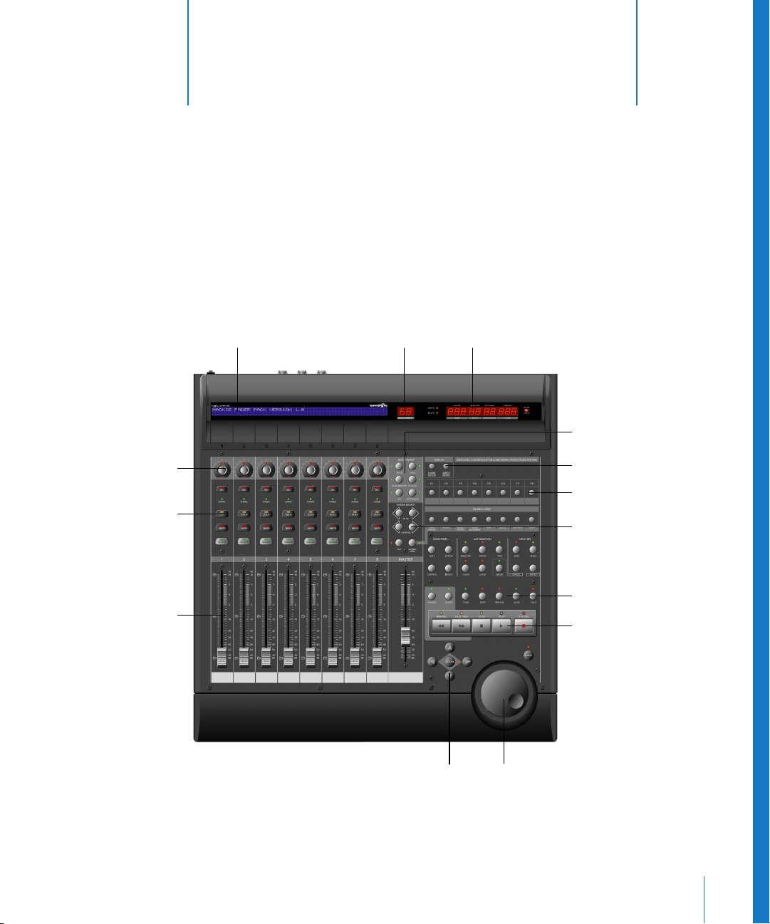
2 Logic Control—Details
LCD Assignment Display Time Display
V-POTs
Rec Rdy, Solo, Mute,
and Select keys
Faders
Jog Wheel
Cursor keys
Transport
Control Buttons
Assignment Buttons
Display Buttons
Channel Buttons
Function Keys
2
This chapter will introduce you to the front panel of the Logic Control. It is assumed
that you are familiar with the basic use and terminology of Logic. As such, we will not
cover the functionality and uses of the individual Logic parameters themselves. Please
consult your Logic reference manual or online help files, if you require further
information.
27
Page 28

We strongly encourage you to press the buttons, turn the V-POT knobs etc. as you’re
reading through this chapter (not that you probably need much encouragement). This
will help you to get a “feel” for how the Logic Control works, and how the various parts
of the control surface interact with one another.
Topics in this chapter are broken down into “Zones” of the Logic Control surface.
The Channel Strip(s)
As each channel strip is identical, the information discussed in this section applies
equally to all eight channel strips on the Logic Control and Logic Control XT units.
V-POT/V-SELECT
This “soft” potentiometer can be used to adjust the send level and pan, plus any other
parameter for EQ, instruments, effects etc. The V-POT can also be used to choose
items—such as plug-ins, Audio Instruments and more—from scrollable lists, and to
determine destinations for sends.
The V-POT also contains an integrated V-SELECT push button. This button generally sets
a “default” parameter value (where a parameter has more than two possible values), or
toggles between two parameter values (e. g on/off ). The V-SELECT can also be used to
activate a function, selected through use of the V-POT. As an example, the V-POT can be
rotated in order to select an effect plug-in for a particular channel Insert slot. Once the
desired effect is displayed in the LCD, a simple press downwards on the top of the V-
POT
will activate the V-SELECT switch. In the example given, this would select, and insert,
the effect and launch the plug-in window. On occasion, the V-SELECT is used to switch
to a special Assignment mode.
The current value of any parameter being adjusted by the V-POT is displayed on the
LCD (dependent on the NAME/VALUE setting), and is also indicated by the ring of LEDs
which surround it. The various LED “ring” displays are shown here:
This will vary as follows, dependent on the selected parameter:
• Connected series of LED segments from left to right (e. g. send level)
• Single segment (e. g. panorama, frequency)
• Connected series of LED segments, starting in the center position and fanning to the
left OR right (e. g. EQ gain)
28 Chapter 2 Logic Control—Details
Page 29
• Series of connected LED segments, starting in the center position and fanning to the
left AND right (e. g. Q-Factor)
• An LED dot below the V-POT indicates when the parameter value is in the centered/
default position
Holding down the C/ALT button sets the V-POTs to high resolution parameter
adjustment mode, where applicable.
Holding down the OPTION button toggles the V-POT between the minimum/maximum
parameter value.
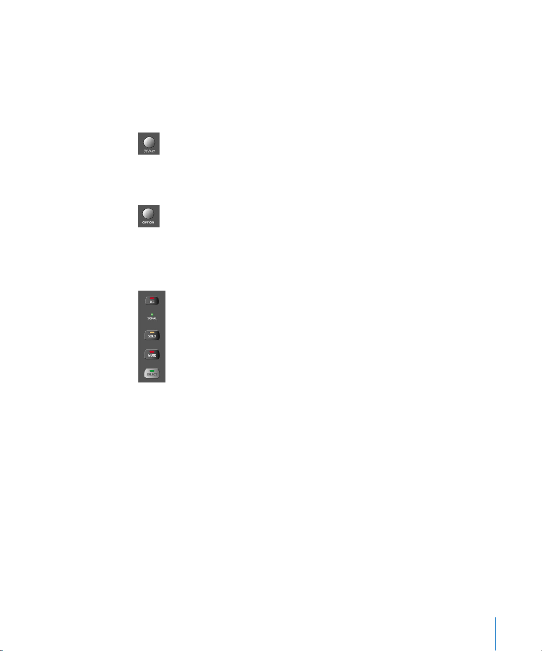
Rec/Rdy (Record/Ready) Switch
This switch arms or disables the channel for recording. Each channel features an
independent Rec/Rdy LED which illuminates when a track is “armed” for recording.
Holding down the OPTION button, while pressing any REC/RDY button will disarm all
tracks.
In Global View, if you arm an audio channel which is currently not used by any track in
the song, and then start recording, you will be asked if you want to create a new track
with this audio channel in the current recording folder.
Signal LED
Indicates the presence of any outgoing MIDI or audio signal. When recording, the
presence of an incoming signal will be indicated.
Solo Switch
For isolating a channel’s signal. Each channel features an independent Solo LED which
illuminates when a track is soloed. The Rude Solo LED—just to the right of the Position/
Time Display LED—also illuminates whenever any track is soloed.
Chapter 2 Logic Control—Details 29
Page 30

Holding down the OPTION button, while pressing any SOLO button will disable solo for
all tracks.
In the “Send Destination/Level” views (see the Send Assignment Modes section, from
page 39 onwards), the SOLO button controls the Pre/Post mode selection—in both
Multi Channel and Channel Strip views.
Mute Switch
Used to defeat the track’s signal. Each channel features an independent Mute LED
which illuminates when a track is muted.
Holding down the OPTION button, while pressing any MUTE button will unmute all
tracks.
In the “EQ Frequency/Gain” and “Send Destination/Level” views, the MUTE button
controls the EQ bypass or Send mute function. This affects both Multi Channel and
Channel Strip views.
Select Switch
This switch is used to select a channel for channel-based editing or assignment
commands. Each channel features an independent SELECT LED which illuminates when
a track is selected.
When holding down the SHIFT button, pressing any channel SELECT button will set the
track’s volume to unity level (0 dB).
While holding down SHIFT, a SELECT button’s LED indicates if the track’s volume is set
to 0 dB.
When holding down the OPTION button, pressing any channel SELECT button will create
a new track with the same instrument of the selected track and switch to Arrange View.
When holding down the SHIFT and OPTION buttons, pressing any channel SELECT
button will create a new track with the next instrument of the selected track and
switch to Arrange View.
30 Chapter 2 Logic Control—Details
Page 31
Touch-Sensitive Motor Fader
These 100mm faders are for controlling the channel’s levels. They transmit 1,024
discrete “steps” as a 10 Bit value, making their use very smooth. When FLIP is activated,
the parameter currently assigned to the V-POT can be controlled with the fader. This
allows you to more easily control pans, aux returns, MIDI track parameters, EQs, Plug-in,
Audio Instrument or other channel parameter levels/values. Please see the Logic
Reference Manual for further information. The eight faders move relative to the activity
of the currently chosen Bank of on-screen faders. The Fader Bank is shifted when one of
the FADER BANK buttons is pressed.
Fader Behavior in Other Modes
• In Flip mode: duplicates or swaps with V-POT of same channel.
• In Surround Angle/Diversity View: adjust surround diversity
• In EQ Frequency/Gain View: adjust gain of selected EQ band
• In Send Destination/Level Multi Channel View: adjust send level of selected send
• In Send Destination/Level Channel Strip View: adjust send level of send on selected
track
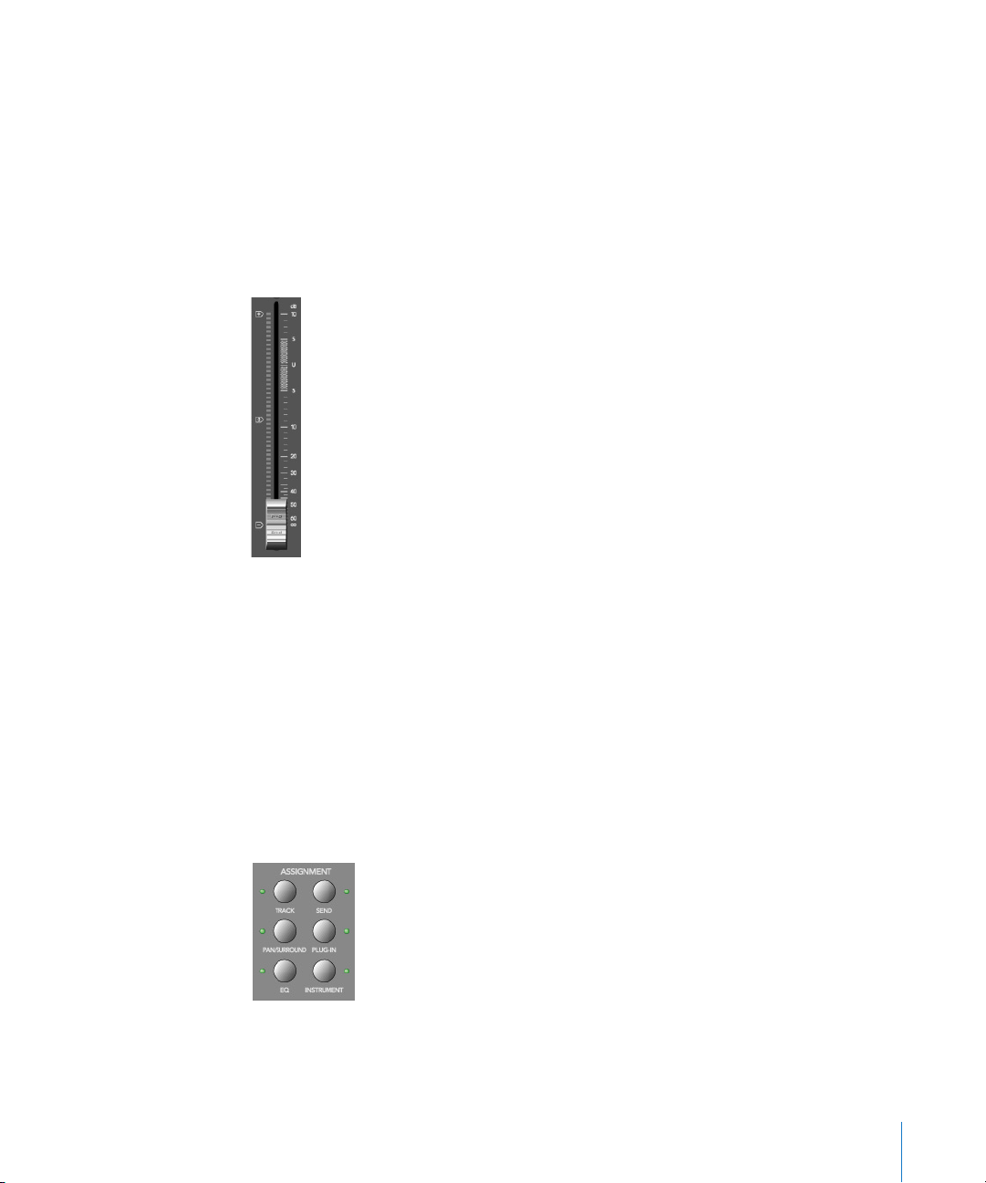
The Assignment Zone
The small light gray area just below the Mode Display contains six buttons.
These ASSIGNMENT buttons work in both Track and Global View modes. View modes are
discussed in View Modes section, from page 17 onwards.
Chapter 2 Logic Control—Details 31
Page 32

When these buttons are pressed, the Mode Display, plus the LED associated with each
button, will update to reflect the currently selected assignment “mode”. The LCD will
also update to display the parameters relevant to the selected Assignment. These
parameters, are, of course assigned to the corresponding V-POTs.
All ASSIGNMENT buttons work as toggle switches, which means that if you click them
repeatedly, they will switch between the Multi Channel and Channel Strip View modes.
• Multi Channel View—you see the same parameter for multiple channels. In Multi
Channel View, the Mode Display does not show a period—e. g.
• Channel Strip View—you see multiple parameters for a single channel. In Channel
Strip View, the Mode Display shows a period to the right—e. g.
P1
P1.
Switching between Multi Channel and Channel Strip views is achieved by pressing the
selected ASSIGNMENT button multiple times.
When pressing an ASSIGNMENT button which is not currently selected, the Assignment
mode changes, and the view switches to Multi Channel View. Exception: switching
between Instrument Edit View and Plug-in Edit View retains Channel Strip View.
The NAME/VALUE button also has an effect on what is shown on the LCD when in the
Multi Channel and Channel Strip views. More information can be found in Display Zone
section, from page 49 onwards.
Changing Parameters and Values
Individual parameters can be adjusted via the associated V-POT (or fader, if the FLIP
button is active), located directly below the parameter entry in the LCD.
To do so, simply grab and turn the desired V-POT. Once the required parameter value is
visible in the LCD, simply release the knob.
Press the V-SELECT button to set the default value (for parameters which have more
than 2 values), or to toggle between two values for parameters with only two
possibilities (e. g on/off).
Some parameters require that a “confirmation” be made, such as Plug-ins, Audio
Instruments, Sends, Inputs and Outputs etc. For these types of parameters, press the V-
SELECT
switch (press down on the top of the V-POT) to activate/select the desired value.
In the case of a plug-in or Audio Instrument, this will automatically launch the Plug-In
window in Logic. For a Send, the confirmed channel Send destination will be activated in
Logic’s Mixer(s).
When a value has been pre-selected, but not confirmed/instantiated (such as Send
Destination, Plug-In insertion etc.) the value will flash until the V-SELECT switch is
pressed.
An exponential increase in value changes will occur as a V-POT is rotated faster.
32 Chapter 2 Logic Control—Details
Page 33

V
Audio1 Audio2 Audio3 Audio4 Audio5 Audio6 Audio7 Audio8
+0.1dB -1.8dB +01.dB -30.0
+0.0dB -50.2
V
Track Assignment Modes
The TRACK button selects Assignment modes which allow the editing of a number of
global track parameters. It toggles between all displayed channels and the individual
parameters of the selected channel (Track Multi Channel View or Track Channel Strip
View). The parameters in Track Multi Channel View include: Volume, Pan, Track Mode,
Track Input, Track Output and Automation. In Track Channel Strip View however you get
an overview of the most important track parameters: Volume, Pan, Instrument, Insert 1,
Insert 2, Send 1 Level, Send 2 Level and Send 3 Level.
Multi Channel View
Track Multi Channel View allows you to edit a single “global” track parameter for all
tracks: Volume, Pan, Track Mode, Input, Output or Automation. The parameter being
edited will be displayed briefly when switching to this mode.
• The Mode Display will show
The upper LCD row shows track names.
Audio1 Audio2 Audio3 Audio4 Audio5 Audio6 Audio7 Audio8
olume Volume Volume Volume Volume Volume Volume Volume
By pressing NAME/VALUE, you can toggle the display mode and instead see the
parameter values in the lower row:
(for “Track”).
tr
-24.7
-1.2dB
As these display variants can be toggled in all Multi Channel Strip Views similarly, the
following will only show displays in Value mode.
• Turning the V-POTs change the associated track parameter
• Pressing a V-SELECT sets the parameter to its default value
• CURSOR LEFT/RIGHT buttons switch to the next or previous track parameter. The
selected parameter will be displayed briefly in the upper LCD row.
Channel Strip View
Track Channel Strip view allows you to edit all parameters listed above, for the selected
track.
• The Mode Display will show
• The upper LCD row shows the name of the track and “Track parameters”.
Track 1 "Audio 1"
olume Pan
Inst
(for “track channel strip”).
tr.
Ins.1
Ins.2
Send 1 Send 2 Send 3
Track parameters
Chapter 2 Logic Control—Details 33
Page 34

V
V
By pressing
NAME/VALUE
, you can toggle the display mode and instead see the
parameter names in the upper row and parameter values in the lower row:
olume Pan
+0.5dB 0
Inst
ES2
Ins.1
Dstrtn AutFlt -54.0
Ins.2
Send 1 Send 2 Send 3
-27.0
-oo dB
As these display variants can be toggled in all Channel Strip Views similarly, the
following will only show displays in Value mode.
V-POT/V-SELECT 1
—edits Volume . The lower LCD row shows the current track volumes,
either in dB or numeric format, depending on the settings of the Environment
objects.
V-POT/V-SELECT 2
—edits Pan position. The lower LCD row shows the current track pan
value ranging from - 64 to + 63 . A value of 0 is the centered position. If Surround is
selected as the Output value, this controls the Surround Angle .
—selects the Instrument of Audio Instrument tracks. Confirm with
V-POT 3
V-POT/V-SELECT 4
Instrument tracks. Confirm with
V-POT/V-SELECT 6
5
and
—select the Plug-in of inserts 1 and 2 of Audio and Audio
V-SELECT
to
8
—edit Send Level of Sends 1 to 3.
.
While the SHIFT button is held down, pressing one of the MUTE button or
V-SELECT 3
V-SELECT
toggles mute or bypass:
1
and 2—toggles the Track’s Mute
—toggles Mute of the Instrument of Audio Instrument tracks.
3
4
5
and
—toggle Bypass of the
Plug-in
of inserts 1 and 2 of Audio and Audio
Instrument tracks.
•
6
to 8—toggle
Mute
of Sends 1 to 3.
.
s
Shortcuts Menu
Holding down the
olume Pan
•
The Mode Display will show
•
V-SELECT 1
•
TrkMod Input
or F1—switches to
The LCD’s lower line shows the current volume of the tracks, in dB or numerically,
button accesses a further sub-menu in the LCD.
TRACK
Output Auto
(for “Track_”)
t
_
Track Multi Channel View
and selects
Setup
Volume
.
depending on the Environment Objects’ setting in Logic.
• Turning a V-POT changes the volume;
• pressing a V-SELECT sets the volume to Unity (val 90/0.0dB)
• V-SELECT 2 or F2—switches to Track Multi Channel View and selects Pan.
• V-SELECT 3 or F3—switches to Track Multi Channel View and selects Track Mode
• V-SELECT 4 or F4—switches to Track Multi Channel View and selects Input
• V-SELECT 5 or F5—switches to Track Multi Channel View and selects Output
• V-SELECT 6 or F6 —switches to Track Multi Channel View and selects Automation Mode
34 Chapter 2 Logic Control—Details
•
•
•
•
•
•
•
•
Page 35

V-SELECT
7 or F7—switches to Track Multi Channel View and displays the automation
parameter selected for display in the Arrange window. Also switches to Arrange View.
or
V-SELECT 8
—switches to Track Setup Channel Strip View (see below).
F8
Track Setup Channel Strip View
In this mode rarely used parameters can be edited for the selected track.
V-POT/V-SELECT 1
V-POT/V-SELECT 2
V-POT/V-SELECT 3
V-POT/V-SELECT 4
V-POT/V-SELECT 5
V-POT/V-SELECT 6
—edits Track Mode (mono, stereo, left, right).
—selects the Surround Mode . Confirm with
—selects the Track Input . Confirm with
—selects the Track Output . Confirm with
V-SELECT 2
V-SELECT 6
V-SELECT 7
.
.
.
—edits Automation Mode .
—edits Track Group Membership . You can choose only one group or
“Off”. To make a track a member of multiple groups, use Group Edit Mode (see
below).
Pan/Surround Assignment Modes
Briefly pressing the
and Pan/Surround Channel Strip View .
Multi Channel View
Pan/Surround Multi Channel view allows you to edit one pan/surround parameter on
all tracks: Angle or pan (on non-surround tracks), Radius (diversity) , LFE, surround mode
(on surround tracks). The parameter being edited will be displayed briefly when
switching to this mode. Regardless of which surround parameter is selected and active,
non-surround tracks always display the standard Pan
PAN/SURROUND
button toggles between Pan/Surround Multi Channel
editing control.
In a song that has both surround and non-surround tracks, you can edit a specified
surround parameter for surround tracks, while the
V-POT
of non-surround tracks will
edit Panning, as usual.
•
The
Mode Display
The upper LCD row shows track names
•
•
Turning the
The
Surround Angle
•
will show Pn (for “Pan”).
•
•
V-POT
s changes the pan/surround parameter
parameter rotates between 0 and 359 degrees, avoiding any
•
•
•
•
angle limit.
•
Pressing a
•
CURSOR LEFT/RIGHT
V-SELECT
sets the parameter to its default value
switches to the next or previous surround parameter. The selected
parameter will be displayed briefly in the upper LCD row.
Chapter 2 Logic Control—Details
•
•
35
Page 36

Channel Strip View
Pan/Surround Channel Strip View allows you to edit all surround parameters for the
selected track.
• The Mode Display will show
• The upper LCD row shows the name of the track and “Pan/Surround”.
(for “Pan/Surround channel strip”).
Pn.
Track 1 "Audio 1"
SrrAng SrrDvr SrrLFE Mode
Pan/Surround
• V-POT/V-SELECT 1—edits angle (or pan on non-surround tracks)
• V-POT/V-SELECT 2—edits diversity
• V-POT/V-SELECT 3—edits LFE level
• V-POT 4—selects the surround mode. Confirm with V-SELECT 4.
• V-POT/V-SELECT 5—edits Surround X
• V-POT/V-SELECT 6—edits Surround Y
The Angle/Diversity and X/Y pairs influence each other. Only the Angle/Diversity
parameters are automated and recorded.
Alternate Mode Options
Holding down the PAN/SURROUND button accesses a further sub-menu in the LCD:
Angle
Radius LFE
• V-SELECT 1 or F1—switches to Pan/Surround Multi Channel View and selects angle
• V-SELECT 2 or F2—switches to Pan/Surround Multi Channel View and selects diversity
• V-SELECT 3 or F3—switches to Pan/Surround Multi Channel View and selects LFE level
• V-SELECT 4 or F4—switches to Pan/Surround Multi Channel View and selects surround
Mode
CStrip
Ang/Dv
mode
• V-SELECT 6 or F5—switches to Pan/Surround Channel Strip View
• V-SELECT 7 or F6—switches to Surround Angle/Diversity Multi Channel View:
• the Mode Display will show
(for “Angle/Diversity”)
Ad
• the upper LCD row shows track names
• the lower LCD row shows the surround angle currently assigned to each track
• turning a V-POT changes the surround angle (or adjusts pan position on non-
surround tracks)
• pressing a V-SELECT sets the surround angle to its default
• the faders edit surround diversity
• V-SELECT 8 or F7—switches to Surround X/Y Multi Channel View:
• the Mode Display will show
(for “X/Y”–the X character is not available on a 7
XY
segment display)
• the upper LCD row shows track names
• the lower LCD row shows the surround X value currently assigned to each track
36 Chapter 2 Logic Control—Details
Page 37

•
turning a
V-POT
changes the surround X value ( or adjusts pan position on non-
surround tracks)
•
pressing a
•
the faders edit surround surround Y
V-SELECT
sets surround X to its default
Notes on Surround X/Y editing
X and Y have the value range − 1000 to + 1000, however the resolution is not that high,
as surround positions are currently recorded in 7 bit only.
Note that X and Y act in a rectangular coordinate system. So value pairs outside the
surround circle are not possible.
When trying to set a value which would lead to an invalid position, the other
coordinate is automatically adjusted to a valid position, e.g. moving Y to + 1000 will lead
X to become 0.
When editing only one coordinate, the other coordinate of the most recently track is
memorized. This helps getting straight movement lines.
EQ Assignment Modes
Briefly pressing the
Strip View .
Multi Channel View
EQ Multi Channel View allows you to edit one equalizer parameter for all
tracks: Frequency , Gain , Q or EQ bypass . The EQ “band” number, and parameter being
edited will be displayed for one second when switching to this mode.
The Mode Display will show
•
•
The upper LCD row shows track names
Turning the
•
•
Pressing a
•
CURSOR UP/DOWN
•
CURSOR LEFT/RIGHT
parameter will be displayed briefly in the upper LCD row.
EQ
button toggles between EQ Multi Channel View or EQ Channel
to
E1
s changes the EQ parameter
V-POT
V-SELECT
sets the parameter to its default value
, dependent on the selected EQ band number.
E8
switches to the next or previous EQ
switches to the next or previous EQ
band
.
parameter
. The selected
•
Pressing a MUTE button while the SHIFT button is held down toggles the current EQ
band’s Bypass status.
•
When Flip Mode is enabled, the
Bypass
status.
Chapter 2 Logic Control—Details
MUTE
buttons display and edit the current EQ band’s
37
Page 38

Channel Strip View
EQ Channel Strip view allows you to edit all EQ parameters—in all bands—for the
selected track.
•
The
Mode Display
• The upper LCD row shows the name of the track, “EQs”, the page number and total
will show
(for “EQ channel strip”).
EQ.
number of pages—e. g. “Page 1/2”.
• V-POT/V-SELECT 1—edits the Frequency of odd-numbered EQs
• V-POT/V-SELECT 2—edits Gain of odd-numbered EQs
• V-POT/V-SELECT 3—edits Q of odd-numbered EQs
• V-POT/V-SELECT 4—edits Bypass of odd-numbered EQs
• V-POT/V-SELECT 5—edits the Frequency of equally-numbered EQs
• V-POT/V-SELECT 6—edits Gain of equally-numbered EQs
• V-POT/V-SELECT 7—edits Q of equally-numbered EQs
• V-POT/V-SELECT 8—edits Bypass of equally-numbered EQs
• CURSOR LEFT/RIGHT switches to the next or previous EQ band. The number of EQ
bands displayed on the LCD depends on the number of Logic Control (XT) units (two
EQ “bands” per unit) available.
Alternate Mode Options
Holding down the EQ button accesses a further sub-menu in the LCD:
• The Mode Display shows
or
E
., dependent on whether you were in EQ Multi
E
_
_
Channel or EQ Channel Strip view
• V-SELECT 1 or F1—switches to EQ Multi Channel View and selects Frequency
• V-SELECT 2 or F2—switches to EQ Multi Channel View and selects Gain
• V-SELECT 3 or F3—switches to EQ Multi Channel View and selects Q
• V-SELECT 4 or F4—switches to EQ Multi Channel View and selects Bypass
• V-SELECT 6 or F6—switches to EQ Channel Strip View
• V-SELECT 7 or F7—switches to Frequency/Gain Multi Channel View. In this mode you
can edit the Frequency and Gain parameters of a specific EQ band (1 to 8) for all
tracks.
• the Mode Display will show
• the upper LCD row shows track names
• the lower LCD row shows the Frequency of the selected EQ
• turning a V-POT changes EQ Frequency
• pressing a V-SELECT sets the EQ Frequency to its default value
• use the MUTE buttons to Bypass the EQ
• use the faders adjust the EQ Gain
• V-SELECT 8 or F8—switches to Frequency/Gain Channel Strip View. In this mode you can
to F8, depending on the selected EQ band
F1
edit the Frequency and Gain parameters for all EQ bands of the selected track. Each
pair of channel strips corresponds to one of the EQ bands.
38 Chapter 2
Logic Control—Details
Page 39

• the Mode Display will show
• V-POTs 1 to 8 control EQ band 1 to 8 Frequency
• MUTE buttons 1 to 8 control EQ band 1 to 8 Bypass
• FADERs 1 to 8 control EQ band 1 to 8 Gain
FG.
Note that in this mode, the faders form a frequency response curve, if the EQ bands
have ascending frequency values.
You can edit another track’s EQs by simply selecting the track, without leaving this view
mode.
Send Assignment Modes
Briefly pressing the SEND button toggles between Send Multi Channel or Send Channel
Strip View.
Multi Channel View
Send Multi Channel view allows you to edit one Send parameter for all
tracks: Destination, Level, Position and Mute. The Send “slot” number, and parameter
being edited will be displayed for one second when switching to this mode.
• The Mode Display will show
• The upper LCD row shows track names
• Turning the V-POTs changes the Send parameter
• Pressing a V-SELECT confirms the pre-selected Send Destination and set the other send
parameters to their default.
• CURSOR UP/DOWN switches to the next or previous Send “slot”.
• CURSOR LEFT/RIGHT switches to the next or previous Send parameter. The selected
parameter will be displayed briefly in the upper LCD row.
to S8, depending on the selected Send “slot”.
S1
• Pressing a MUTE button while the SHIFT button is held down toggles the current
Send’s Mute status.
• When Flip Mode is enabled, the MUTE buttons display and edit the current Send’s
Mute status.
Tip: Ensure that the ZOOM button isn’t active when using the CURSOR keys.
Chapter 2 Logic Control—Details 39
Page 40

Channel Strip View
Send Channel Strip view allows you to edit all Send parameters for the selected track.
• The Mode Display will show
• The upper LCD row shows the name of the track, “Sends”, the page number and total
(for “Send channel strip”).
SE.
number of pages—e. g. “Page 1/4”
Track 1 "Audio 1"
Snd3Ds Send 3
Snd3Ps Snd3Mt Snd4Ds Send 4
Sends
Page 1/2
Snd4Ps Snd4Mt
• V-POT/V-SELECT 1—edits Destination of odd-numbered Sends
• V-POT/V-SELECT 2—edits Level of odd-numbered Sends
• V-POT/V-SELECT 3—edits Position (pre/post) of odd-numbered Sends
• V-POT/V-SELECT 4—edits Mute of odd-numbered Sends
• V-POT/V-SELECT 5—edits Destination of even-numbered Sends
• V-POT/V-SELECT 6—edits Level of even-numbered Sends
• V-POT/V-SELECT 7—edits Position (pre/post) of even-numbered Sends
• V-POT/V-SELECT 8—edits Mute of even-numbered Sends
• With the horizontal Cursor buttons you shift pages. The number of Sends which are
displayed simultaneously depends on the number of Logic Control XTs you have.
Alternate Edit Mode Options
Holding down the SEND button accesses a further sub-menu in the LCD:
• The Mode Display shows
or
S
., depending on whether you were in Send Multi
S
_
_
Channel or Send Channel Strip View
Dest
Pos
Level
Mute
CStrip CSt2
Ds/LvM Ds/LvC
• V-SELECT 1 or F1—switches to Send Multi Channel View and selects Destination
• V-SELECT 2 or F2—switches to Send Multi Channel View and selects Send Level
• V-SELECT 3 or F3—switches to Send Multi Channel View and selects Position
• V-SELECT 4 or F4—switches to Send Multi Channel View and selects Mute
• V-SELECT 5 or F5—switches to Send Channel Strip View
• V-SELECT 6 or F6—switches to Send Channel Strip 2 View:
This mode is similar to Send Channel Strip View, however the parameters are arranged
in a different way. You can control one parameter of all Send “slots” for the selected
track.
• The Mode Display will show
40 Chapter 2 Logic Control—Details
(for “Send channel strip”).
SE.
Page 41

The upper LCD row shows the name of the track, “Sends”, the page number and
•
total number of pages—e.
g. “Page 1/4”
Track 1 "Audio 1"
Snd1Ds Snd2Ds Snd3Ds Snd4Ds Snd5Ds Snd6Ds Snd7Ds Snd7Ds
V-POT/V-SELECT 1
With the horizontal Cursor buttons you shift pages. The number of parameters
•
8
to
—edits the displayed parameter
Sends
Page 1/2
which are displayed simultaneously depends on the number of Logic Control XTs
you have.
V-SELECT 7
F7
or
—switches to Destination/Level Multi Channel View :
In this mode you can control one Send “slot” for all tracks. Each channel strip
corresponds to the track shown in the upper LCD row.
•
the Mode Display will show
the upper LCD row shows track names
•
•
the lower LCD row shows the destination of the selected Send
turning a
•
•
pressing a
•
SOLO
the
the
•
MUTE
•
the faders edit Send Level
•
V-SELECT 8
pre-selects the Send Destination
V-POT
V-SELECT
confirms the pre-selected Send Destination
buttons edit Send Position —
buttons edit Send Mute
or
F8—switches to
In this mode you can control all
corresponds to the
the
Mode Display
•
•
turning a
•
pressing a
• the SOLO buttons edit Send Position—SOLO LED on means “Pre Fader”
• the MUTE buttons edit Send Mute
• the faders edit Send Gain
V-POT
Send
number embossed below the LCD.
will show
pre-selects the corresponding
V-SELECT
confirms a preselected
to
d1
Destination/Level Channel Strip View
dL.
, depending on the selected Send
d8
SOLO
LED on means “ Pre Fader ”
:
Send
slots for the selected track. Each channel strip
•
Send Destination
Send Destination
•
If one or more Sends are activated on multiple channels, you can switch between them
in the Channel Strip Views by simply pressing the SELECT button for the desired
channel.
Chapter 2 Logic Control—Details
41
Page 42

Plug-In Assignment Modes
Pressing
Please note that there is one exception to this behavior: if you are in Instrument Edit
View , pressing this button switches to Plug-in Edit View .
Multi Channel View
This mode shows the plug-ins associated with a particular Insert “slot” for all channels.
•
•
•
•
•
•
PLUG-IN
The Mode Display will show
toggles between Plug-in Multi Channel or Plug-in Channel Strip View .
to
P1
, or simply 10 to 16, dependent upon the selected
P9
Plug-In Insert “slot” number. Note that if an Audio Instrument channel is selected, the
display will show
P1
to
P9
and 10 to 15
.
The upper LCD row shows track names.
The lower LCD row shows the currently selected plug-in for this insert slot. Muted
plug-ins are shown with an asterisk
Turning the
s pre-selects a new plug-in. Until confirmed with the
V-POT
which precedes the plug-in name.
*
V-SELECT
, the
plug-in name flashes.
Turning another
will cancel any previous pre-selection and will start pre-
V-POT
selection on the newly selected track.
Pressing a
•
confirms/activates the pre-selected plug-in (assuming that you’ve made your pre-
V-SELECT
selection by turning the
•
opens a plug-in editor window, if none are opened. If a plug in window is opened,
:
)
V-POT
and link mode is enabled, the selection of another plug-in will replace the existing
plug-in shown.
•
switches to
Plug-in Edit View
To remove a plug-in, pre-select the value of “--” (by turning the
counterclockwise), and press the V-SELECT linked to the appropriate Insert slot. Logic
Control will not switch to Plug-In Edit view, and no Plug-In window will be launched. If
one was previously opened, it will be closed (if the “chain” icon is inactive).
• The CURSOR UP/DOWN buttons change the currently displayed Plug-in Insert slot (1 to
8).
• Pressing a V-SELECT while the SHIFT button is held down will mute/unmute the plug-
in.
• Pressing a MUTE button while the SHIFT button is held down toggles the will mute/
unmute the plug-in.
42 Chapter 2
Logic Control—Details
V-POT
all the way
Page 43

Channel Strip View
This mode shows the plug-ins associated with all Insert “slots” for the selected channel.
• The Mode Display will show
• The upper LCD row shows Ins1Pl through Ins8Pl
• The lower LCD row shows the plug-in which is currently selected for this insert slot.
PL.
Muted plug-ins are indicated by an asterisk *, which precedes the plug-in name.
• Turning the V-POTs pre-selects a new plug-in. Until activated, the plug-in name
flashes.
• Turning another V-POT will cancel any previous pre-selection and will start pre-
selection on the newly selected track.
• Pressing a V-SELECT:
• activates the pre-selected plug-in (assuming that you’ve made your pre-selection
by turning the V-POT)
• opens a plug-in editor window if none are opened (if a plug in window is opened,
and link mode is enabled, the selection of another plug-in will replace the existing
plug-in)
• switches to Plug-in Edit View
To remove a plug-in, pre-select the value of “--” (by turning the V-POT all the way
counterclockwise), and press the V-SELECT linked to the appropriate Insert slot. Logic
Control will not switch to Plug-In Edit view, and no Plug-In window will be launched. If
one was previously opened, it will be closed (if the “chain” icon is inactive).
• Pressing a V-SELECT while the OPTION button is held down will mute/unmute the
plug-in
Plug-in Edit View
• The Mode Display will show
P1.
to
, depending on the number of the selected
P8.
Plug-In Insert “slot”.
• Dependent on the NAME/VALUE button, the LCD display will change in the following
ways between the two modes:
• Name The upper LCD row shows the track’s name, insert number, plug-in name,
current parameter page and total number of parameter pages.
The lower LCD row shows the name of the parameter which is edited via the V-POT
below.
• Value The upper LCD row shows the name of the parameter which is edited via
the V-POT below.
The lower LCD row shows the current value of the parameter edited with the V-POT. If
there is sufficient onscreen space, the unit type will be added—e. g. Hz.
• Turning the V-POTs changes the parameter
Chapter 2 Logic Control—Details 43
Page 44

• Pressing a V-SELECT sets the parameter to its default value, except where the
parameter only has two values (on/off, for example). In this case, pressing the V-
toggles between these values.
SELECT
• The CURSOR LEFT/RIGHT buttons switch to the next or previous parameter page.
Note that when shifting by a “page”, this always “quantizes” to integer pages. As an
example:
• the plug-in has 19 parameters
• Logic Control shows parameters 1 to 8
• CURSOR RIGHT shifts to 9 to 16
• CURSOR RIGHT shifts to 12 to 19
• CURSOR LEFT shifts back to 9 to 16, not to 4 to 11
This way, you always revert to the page positions you expect to find, and are
comfortable with.
• To switch by a single parameter, rather than by “page”, hold down the C/ALT key
while pressing the CURSOR LEFT/RIGHT button.
• The CURSOR UP/DOWN buttons change the currently displayed Plug-in insert slot (1 to
8)
N. B. If you have a Control Surface Group consisting of several physical units, the
parameters are distributed across their displays. The number of parameters shown is
dependent on the settings in the Preferences, as discussed in the Logic Reference
Manual.
When exiting Plug-In Edit View, the Plug-In window will be closed (if the “chain” icon is
inactive).
Compatibility
Logic Control can edit all plug-ins which have automatable parameters. The plug-in
type (built-in, TDM, VST, DirectX) is irrelevant.
DirectX supports automatable parameters since version 8. However it is not sufficient
to install this version—the DirectX plug-ins must also support the new functions.
44 Chapter 2 Logic Control—Details
Page 45

Some plug-ins however don’t provide parameter names and/or values as text. In this
case the parameters are enumerated as “Control #1”, “Control #2” etc., and the values are
displayed as numbers between 0 and 1000.
Some VST plug-ins don’t allow to retrieve the value range; in this case the range 0 to
1000 is assumed. This is disturbing with switches, as they can’t be toggled with V-POTs
nor with V-SELECTs. In this case hold down OPTION and turn the V-POT.
Please contact the plug-in’s manufacturer in order to get a version which supports the
mentioned features.
Instrument Assignment Modes
Pressing the INSTRUMENT button switches to “Instrument Multi Channel” view.
Please note that when in Plug-In Edit view, pressing the INSTRUMENT button will switch
to Instrument Edit View.
If you can’t see the Audio Instrument channels, use the BANK or CHANNEL buttons in
the FADER BANKS zone, or switch to Global View by pressing the AUDIO INSTRUMENT
button. (This assumes that you have created at least one or more Audio Instrument
channels in the Environment Audio layer).
Multi Channel View
This mode shows the Instrument Insert “slot” (slot 1) for all channels.
• The Mode Display will show
• The upper LCD row shows track names
• The lower LCD row shows the currently selected Instrument. Muted Instrument
names are preceded by an asterisk *
• Turning the V-POTs pre-selects a new Instrument. Until activated, the pre-selected
Instrument name flashes.
• Turning another V-POT will cancel any previous pre-selection and will start pre-
selection on the newly selected track.
• Pressing a V-SELECT:
• activates the pre-selected Instrument plug-in (assuming that you’ve made your
pre-selection by turning the V-POT)
• opens a plug-in editor window, if none are opened. If a plug in window is opened,
and link mode is enabled, the selection of another Instrument plug-in will replace
the existing one.
• switches to Instrument Edit View
In
To remove an instrument plug-in, pre-select the value of “--” (by turning the V-POT all
the way counterclockwise), and press the V-SELECT. Logic Control will not switch to
Instrument Edit view, and no Plug-In window will be launched. If one was previously
opened, it will be closed (if the “chain” icon is inactive).
Chapter 2 Logic Control—Details 45
Page 46
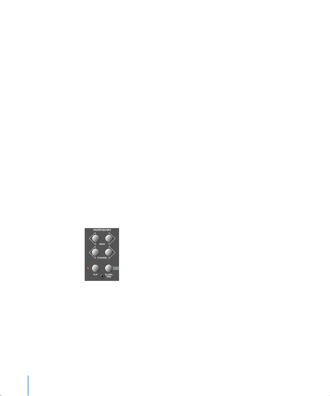
• Pressing a V-SELECT while the SHIFT button is held down mute/unmutes the
Instrument
• Pressing a MUTE button while the SHIFT button is held down mute/unmutes the
Instrument
Instrument Edit View
• The Mode Display will show
• Dependent on the NAME/VALUE button, the LCD changes in the following ways:
• Name—The upper LCD row shows the track’s name, instrument name, current
In.
parameter page and total number of parameter pages. The lower LCD row shows
the name of the parameter edited with the V-POT below it.
• Value—The upper LCD row shows the name of the parameter edited with the V-
POT
below it. The lower LCD row shows the current value of the parameter edited
with the V-POT. If there is sufficient space left, the unit is appended.
• Turning the V-POTs changes the corresponding parameter
• Pressing a V-SELECT sets the parameter to its default value, except where the
parameter only has two values (on/off, for example). In this case, pressing the V-
SELECT
toggles between these values.
Compatibility
The comments in section Compatibility section on page 44 also apply to software
instruments.
Fader Bank Zone
This area of the Logic Control surface contains six buttons.
Bank Left/Right
Moves up or down by “banks” of channels/tracks. To quickly explain, a single Logic
Control is only capable of viewing 8 tracks at a time in either Global or Mixer View. To
see, and edit or mix more tracks, simply press the RIGHT/LEFT BANK buttons to switch
between tracks 1—8, 9—16, 17—24 a. s. o.
The BANK button pair shifts the view section by the number of channels in the Control
Surface Group. E. g. if you have a Logic Control and two Logic Control XT units, the view
shifts by 24 channels.
46 Chapter 2 Logic Control—Details
Page 47

Note that when shifting by bank, this always “quantizes” to integer banks. As an
example:
• your song has 19 tracks.
• Logic Control shows tracks 1 to 8
• BANK Right shifts to 9 to 16
• BANK Right shifts to 12 to 19
• BANK Left shifts back to 9 to 16, not to 4 to 11
This way, you always revert to the bank positions you expect, and are used to.
Channel Left/Right
As per the BANK buttons, but moves up or down in increments of a single channel.
Notes on Fader Bank Editing
When holding down the OPTION button, pressing the BANK LEFT or CHANNEL LEFT
button jumps to the first tracks, and pressing the BANK RIGHT or CHANNEL RIGHT button
jumps to the last tracks in the song—as an example in a 64 track song, tracks 1 to 8 or
tracks 57—64.
The Fader bank offset is memorized separately for Global views where one track type is
displayed (MIDI, Inputs, Audio Tracks, Instruments, Aux, Busses, Outputs+Master), and
there is also a separate fader bank offset for combination of multiple track types. This
feature allows you e.g. to scroll to audio tracks 2 to 9 in Global Audio Track view and to
scroll to instruments 5 to 12 in Global Instruments view. You can switch between the
views without losing the fader bank offset.
Flip
The FLIP button enables/disables the following “flip”, “swap” or “zero” modes:
• If the LED beside the FLIP button is off, flip/swap mode is off. The faders control
volume.
• Pressing the FLIP button enables “flip mode” (the LED goes on): in this mode, the
current assignment of the eight V-POTs are mirrored on the eight channel faders.
Pressing the FLIP button again disables flip mode.
Turning a V-POT in this mode will also move the corresponding fader.
• Pressing the FLIP button while the SHIFT button is held down enables “swap mode”
(the LED will flash): in this mode, the encoder assignments are swapped with the
fader assignments. Pressing SHIFT + FLIP again disables swap mode. As the LCD’s
lower row shows the current value of the encoders, it will show volumes in this
mode.
• Pressing FLIP without SHIFT held reverts to flip mode.
Chapter 2 Logic Control—Details 47
Page 48

• Pressing CONTROL + FLIP switches to zero mode. Pressing CONTROL + FLIP again
disables zero mode. In this mode the faders are set to zero and don’t move. Useful for
acoustic/microphone recordings if Logic Control is located in the recording booth,
and you don’t want to hear/capture any motor noise.
Both flip and swap mode work in all view modes.
Flip mode has the following advantages:
• you can edit any type of parameter with a fader, rather than a V-POT, which allows
more accurate edits
• you can edit with touch-sensitive faders. The V-POTs are not touch-sensitive, and thus
don’t allow existing (controller automation) movements to be overwritten by a
constant value.
Global View
This button is discussed in Global View section, from page 18 onwards.
Master Fader
Controls the level of the Master fader in Logic’s Mixer. This reduces the level of all tracks,
but does not affect their relative positions.
When there is no Master Volume object in the song (or in Logic Express where this
object is not supported), Logic Control’s Master fader maps to Output 1-2.
To set the automation mode of the Master output, you need to select this object. To do
so, press the OUTPUTS button and select the master output with the corresponding
SELECT button.
If you use multiple audio systems simultaneously, the MASTER fader controls only the
first audio system’s Master Volume (in the order as seen in the Audio Preferences
window).
48 Chapter 2 Logic Control—Details
Page 49

Display Zone
These buttons affect what you see in the LCD and Position/Time Display.
Name/Value
To toggle between the two Display formats—Name or Value—repeatedly press the
NAME/VALUE button in the Display section of the Logic Control—just below the SMPTE/
BEATS LEDs. For more information, see the Liquid Crystal Display (LCD) section, from
page 21 onwards.
Pressing the NAME/VALUE button, while holding the SHIFT button, cycles through these
three level meter modes:
• Vertical—In this mode, the sixth (last) character of each channel in both LCD rows is
overlaid by a vertical level meter bar. When the level meter is not visible, the text
character reappears. We chose the last, rather than the first, character for the level
meter, as this character is blank in many cases, so no valuable information is “blocked
out” by the level meter.
Tip: if it disturbs you that the D letter of the dB unit flickers when levels are displayed,
you should switch off display if units. See the Logic Reference Manual.
• Horizontal—with Peak Hold. In this mode, the second row is replaced by horizontal
level meter bars. Peak Hold is shown as a hollow box which disappears after 3
seconds. Overload (clipping) is displayed as an asterisk. It remains on the LCD until
cleared (see below).
• Off—In this mode, no level meters are displayed in the LCD.
In all three modes, the SIGNAL LEDs function as per usual, indicating the presence of a
signal.
N. B. The MIDI bandwidth required for the display of level meters is the same in all three
modes—and is very low. The Position/Time Display updates require much more MIDI
bandwidth than the level meters.
Pressing the NAME/VALUE button, while holding the CONTROL button, clears Overload
(clipping) in both Logic’s Environment/Track Mixer, and the horizontal level meters on
the Logic Control.
Pressing the NAME/VALUE button, while holding the CMD/ALT button, enters “Control
Surface Group Settings Mode”. Here you can edit several control surface group settings,
some of which are not accessible with a single button:
Chapter 2 Logic Control—Details 49
Page 50

• V-POT/V-SELECT 5 (label “TrkNam”)—sets track name display format
“Name”—track name only
“#:Name”—track number and name
This parameter can also be toggled with OPTION+NAME/VALUE
• V-POT/V-SELECT 6 (label “Lock”)—toggles Channel Strip View track lock
“Off”—as you are used to: selecting a track also switches the currently edited
Channel Strip track
“On”—the currently edited Channel Strip Track is not affected by selecting a track.
When you switch from On to Off, this also updates the Channel Strip track
To edit another track in Locked mode, first disable Lock, then select the desired track,
then re-enable Lock
• V-POT/V-SELECT 7 (label “Disply”)—toggles LCD display format
“Name”—upper line displays global info, lower line displays parameter names
“Value”—upper line displays parameter names, lower line displays parameter values
This parameter can also be toggled with NAME/VALUE.
• V-POT/V-SELECT 8 (label “Clock”)—toggles Clock display format
“Beats”—clock is displayed in format bars/measures/beats/ticks
“SMPTE”—clock is displayed in SMPTE format
This parameter can also be toggled with SMPTE/BEATS.
Control Surface Group Settings Mode can be left by pressing NAME/VALUE, or by
entering one of the Marker or Nudge modes.
SMPTE/Beats
To toggle between the two Time formats, repeatedly press the SMPTE/BEATS button in
the Display section at the top of the Logic Control—just below the SMPTE/BEATS LEDs.
For more information, see the Song Position/SMPTE Time Display section on page 23.
50 Chapter 2 Logic Control—Details
Page 51

The Function Key Zone
The eight Function Keys—F1 to F8—are assigned as follows:
• F1 to F7 recalls screensets 1 to 7
• F8 closes the top-most window, with “floating” windows closed first.
With the SHIFT key held down, the Function keys toggle particular windows:
• F1—Arrangement
• F2—Track Mixer
• F3—Event Editor
• F4—Score
• F5—Hyper Editor
• F6—Matrix Editor
• F7—Transport
• F8—Audio
With the CMD/ALT key held down, the Function keys trigger common key commands:
• F1—Cut
• F2—Copy
• F3—Paste
• F4—Clear
• F5—Select All
• F6—Select All Following
• F7—Select Similar Objects
• F8—Select Inside Locators
In some other “modes”, the Function keys perform other duties, such as shortcuts to
Markers. Please see the Marker section on page 56. Also see the table towards the back
of this manual.
Chapter 2 Logic Control—Details 51
Page 52

The Global View Zone
The Global View mode is activated by pressing any of the GLOBAL VIEW buttons. When
any is activated, the green LED to the right of the GLOBAL VIEW button will illuminate.
Pressing multiple GLOBAL VIEW buttons simultaneously will display the objects of the
selected types. To do so:
Hold down any GLOBAL VIEW button, and add or remove other object types by
repeatedly pressing the other desired GLOBAL VIEW buttons. The display order of the
objects matches the order of these buttons on the front panel of the Logic Control.
As an example: to see the busses and the outputs, hold down BUSSES, and then press
OUTPUTS.
Further information on Global View is found in the Global View section on page 18.
Function Button Zone
There are three areas in this zone—Modifiers, Automation and Utilities.
Modifier Buttons
The four buttons in this area are similar to those found on your Mac OS or Windows
computer keyboard (however independent from them). Many of Logic’s functions
behave differently when one or more “modifier” key(s) is pressed, in conjunction with
another key or mouse click. This also applies to the Logic Control. All “modified” Logic
Control commands are covered in each function’s description.
A generic, and brief, description of each button follows:
• SHIFT—an alternate function/meaning for a button
• OPTION—the function applies to all objects. For relative value changes: the value is
set to the minimum or maximum, depending on whether you increase/decrease it.
52 Chapter 2 Logic Control—Details
Page 53

• CONTROL—while held down, the Group Clutch is engaged, i.e. Track Groups are
temporarily disabled.
• C/ALT—fine tuning variation of the function.
Automation Buttons
The five buttons in this area activate/deactivate the various automation modes of
Logic. These work in conjunction with the channel SELECT switches. Simply choose the
channel you wish to automate, select the Automation mode via one of these six
buttons, and move the corresponding fader. The modes are outlined below:
• READ/OFF—Pressing this button repeatedly toggles between the “Read” and “Off”
automation modes.
• Off—Automation is off. The fader will neither send nor receive automation data.
Existing automation data remains untouched. It will still behave as a fader,
however, and will adjust the volume or pan position etc. as usual.
• Read—The fader will read (follow) any existing automation data, but will not write
data, regardless of any movements you make with the mouse or external control
device.
• TOUCH—Writes new parameter changes when the fader is “touched” or V-POT turned
during playback. Any existing track automation data (of the current fader type) will
be replaced by new movements as long as the control is active—i.
being touched or V-POT is being turned.
• LATCH—Similar to Touch mode, but the control remains activated, even when the
fader is no longer being “touched” or V-POT being turned. In other words, following
the release of the fader, the current fader value will replace the existing automation
data for as long as the sequencer is in playback mode. Press STOP to finish.
• WRITE—Overwrites all existing automation data, or creates new automation data.
Only use it if you wish to destroy all existing automation data.
• TRIM—Not enabled in the release version of Logic 5.
Please consult the readme files of updated versions.
e. the fader is
Chapter 2 Logic Control—Details 53
Page 54

When the OPTION key is held down, pressing one of the Automation buttons chooses
the selected automation mode for all tracks. When an automation mode has been
selected for all tracks, the button’s LED will illuminate whenever the OPTION key is held.
N. B.—This is slightly different for the “Off” automation mode, when holding down the
OPTION button. While doing so, all automation “writing” buttons will be turned off, but
this does not necessarily mean that all tracks are actually in Off mode—they could also
be in different modes. To ensure that you have set all tracks to Off mode, press READ/
OFF twice (its LED goes on, then off), while holding down the OPTION key.
Group
Pressing the GROUP button enters Group Edit Mode:
• GROUP button’s LED is on
• The Assignment display shows the currently displayed group, e.g. “G1”.
• The Time display shows the group name (10 last characters if name is longer than 10
characters)
• The upper LCD line displays track names
• The lower LCD line displays group parameters
• Group parameters can be toggled with V-SELECTs
• CURSOR UP/DOWN selects previous/next group
• CURSOR LEFT/RIGHT shifts group parameter display
• SELECT buttons display if a track is a member of the group. Pressing a SELECT button
toggles track membership of the group
With Group Edit Mode off, holding down GROUP and pressing one or more SELECT
buttons allows you to create a new group.
Pressing the GROUP button, while the SHIFT button is held down, creates a new group,
opens the Group window and enters Group Edit mode.
Pressing the GROUP button, while the TRACK button is held down, switches to Track
Multi Channel View, displaying the Track Group parameter. It displays which group the
instrument is a member of. Multiple group membership is displayed like in the Track
Mixer window. Turning a V-POT changes group membership. Note that you can only
select one group (or “Off”) here.
54 Chapter 2 Logic Control—Details
Page 55

Utilities Buttons
Save
Saves the current Song file. When pressed, a file save dialog will open on your
computer screen, waiting for you to enter a filename as per usual.
The Logic Control LCD will display There is a file select dialog on the screen
and the Position/Time Display will show
Once the file save has been confirmed—in Logic—the Logic Control will return all
controls to their status prior to invoking the Save command.
Once the song has been saved and given a name, you may freely use the SAVE button
to save any subsequent changes. This will happen without the alert messages and file
save dialog appearing onscreen.
As a general working tip, you should always save your autoload song under a different
name as the first step in any project. If this practice is adhered to, you will be able to
simply press the SAVE button on the Logic Control to incrementally save your work.
The SAVE LED illuminates as soon as any save-able change has been made in Logic.
Holding down the OPTION button while pressing SAVE opens the “Save As.” file select
box.
. All LEDs will go off.
ALErt
Undo
Pressing the UNDO button undoes the last undoable editing step. As Logic 5.1 supports
virtually unlimited multiple undo/redo, The green UNDO LED does not illuminate to
indicate an undo-able step, but to indicate that Redo is available. This warns you that
performing an undoable editing step would render all Redo steps unavailable.
Holding down the SHIFT button while pressing UNDO performs a “Redo”.
Holding down the OPTION button while pressing UNDO opens the Undo History
window.
Cancel
If an alert is open on-screen, it triggers the Cancel (or Abort) button. More information
on alerts is found in About Alert Messages section on page 23. Pressing the CANCEL
button when no alert is opened will launch the Toolbox at the current on-screen
position of the mouse cursor. Alternately, it will perform any function currently
assigned to the computer keyboard Esc key.
If no alert is open, and Logic Control currently displays the contents of a folder track,
the CANCEL button lets you leave the folder.
Chapter 2 Logic Control—Details 55
Page 56

With CANCEL you can also cancel a blinking pre-selection of a parameter value.
Enter
If an alert is open, the ENTER button triggers the default button. See About Alert
Messages section on page 23 for more information.
If no alert is open, and the selected track is a folder track, the ENTER button enters this
folder.
The Transport Zone
This section of the Logic Control features twelve (12) buttons. All are equipped with a
dedicated LED to indicate their current status.
It should be noted that these buttons can be used independently, or in conjunction
with one another, to navigate and edit your songs.
The functionality of these buttons is as follows:
Marker
With the help of the MARKER button you can jump to, create and delete markers.
Marker and Nudge Mode are mutually exclusive; activating one deactivates the other.
Small Marker Mode
Hitting the
They let you jump to the next or previous marker.
Pressing the MARKER button again returns to the default behavior of the FAST FWD and
REWIND (see Rewind section on page 62 and Fast Fwd section on page 62).
Small Marker Mode is useful if you want to jump to markers, but still use the V-POTs for
other purposes.
MARKER button reassigns the behavior of the FAST FWD and REWIND buttons.
56 Chapter 2 Logic Control—Details
Page 57

Large Marker Mode
When pressing the MARKER button while holding down SHIFT, the LCD will update to
display three options, assigned to the first three V-SELECTs.
• V-SELECT 1 to 5—display the first 5 Markers by name. Pressing a V-SELECT sets the
current song position to this Marker. When the current song position is inside a
marker, the lower line displays INSIDE, and the V-POT LED ring is on.
• V-SELECT 6—Cr w/o—Creates a marker without rounding to the nearest bar.
• V-SELECT 7—Create—Creates a marker rounded to the nearest bar.
• V-SELECT 8—Delete—Deletes the marker above the current SPL location.
To create or delete a marker at the current song position, simply press the appropriate
V-SELECT switch.
The creation or deletion of markers is best used in conjunction with the JOG/SCRUB
WHEEL
. Simply move to the desired song position by dialing with the wheel, and then
press the appropriate V-POT.
• For coarse placement, simply use the wheel to move the SPL.
• For fine placement, press the SCRUB button, and then use the wheel to place the SPL.
(Only appropriate if creating or deleting an un-rounded marker).
More information on the JOG/SCRUB WHEEL is found in The Jog/Scrub Wheel Zone section
on page 65.
Large Marker Mode is terminated by pressing MARKER.
Temporary Marker Mode
If you want to enter Marker Mode temporarily (to quickly perform a few marker
functions), hold down the MARKER button and press one or more of the above V-
SELECT
s: this will execute the marker function and leave marker mode as soon as you
release the MARKER button.
• When in this mode—with the MARKER button held—pressing the Function keys F1—
F8 “jumps” to the first 8 markers. As an example, to go to marker 3, press-hold
MARKER and press F3.
• To jump between markers, with (or without) the MARKER button held, simply press
the REWIND or FAST FWD buttons.
Chapter 2 Logic Control—Details 57
Page 58

Nudge
With the help of the NUDGE button, you can nudge selected regions, sequences and
events.
Marker and Nudge Mode are mutually exclusive; activating one deactivates the other.
Small Nudge Mode
Hitting the NUDGE button reassigns the behavior of the FAST FWD and REWIND buttons.
They nudge the selected regions, sequences or events by the value defined in the
Large Nudge Mode (see below).
Pressing the NUDGE button again returns to the default behavior of the FAST FWD and
REWIND (see Rewind section on page 62 and Fast Fwd section on page 62).
Small Nudge Mode is useful if you want to nudge objects, but still use the V-POTs for
other purposes.
Large Nudge Mode
When pressing the NUDGE button while holding down SHIFT, the LCD will update to
display eight options, assigned to the V-POTs and V-SELECTs. All these functions allow
you to move the selected objects (audio region, MIDI sequence or events).
As an indicator, the position of the first selected region, sequence or event is displayed
above V-POTs 3 and 4. If nothing is displayed, either a window is active which does not
allow to select regions, sequences or events, or none are selected.
The functions are as per the following:
• V-POT 1—Nudge—selects the nudge value used by the REWIND and F.FWD buttons.
These buttons move the selected object(s) backwards/forwards by the defined value.
• V-SELECT 2—Pickup—moves to the current song position line location.
• V-POT 3—Bar— moves by 1 bar.
• V-POT 4—Beat—moves by the current song denominator value (beats).
• V-POT 5—Format—moves by the current song format value (sub-divisions—1/16th
etc.).
• V-POT 6—Ticks—moves by single ticks.
• V-POT 7—Frames—moves by one SMPTE frame.
• V-POT 8—Fram/2—moves by a half SMPTE frame.
58 Chapter 2 Logic Control—Details
Page 59

• The cursor buttons always emulate the computer keyboard’s cursor keys. This allows
you to easily select an object.
Large Nudge Mode is terminated by pressing NUDGE.
Temporary Nudge Mode
If you want to use NUDGE temporarily (for one or two “nudges”), hold down the NUDGE
key, and user one or more of the above V-POTs: this will execute the nudge function
and leave “nudge” mode as soon as you release the NUDGE button.
In Temporary Nudge Mode, the cursor buttons always emulate the computer keyboard’s
cursor keys. This allows you to easily select an object.
The Nudge value for the REWIND and F.FWD buttons can also be defined with the
function buttons:
• F1—sets Ticks
• F2—sets Format
• F3—sets Beat
• F4—sets Bar
• F5—sets Frames
• F6—sets Frames/2
Cycle
Activates/deactivates Cycle mode. By default, the cycle region will fall between the first
two Markers.
Subsequent Markers can act as left/right boundaries for further cycle regions.
To “jump” between cycle regions—defined by the Markers:
• Press the MARKER button, to activate it.
• Press the CYCLE button, and when active, press the REWIND or FAST FWD buttons.
Quickly Define a Cycle Locator
To set the left or right locator to the current song position, hold down CYCLE and press
REWIND or FAST FWD. This also enables Cycle.
So the fastest way to define a new cycle region is:
1 navigate to the left locator with the JOG/SCRUB WHEEL
2 press CYCLE + REWIND
3 navigate to the right locator with the JOG/SCRUB WHEEL
4 press CYCLE + FAST FWD
Chapter 2 Logic Control—Details 59
Page 60

Cycle View
Pressing the SHIFT + CYCLE buttons activates Cycle View mode:
• The Mode Display displays
• V-POT/V-SELECT 1—shows and edits the current Cycle status (off or on); you can also
Cy
use the CYCLE button
• V-SELECT 2—BySel— sets the current Cycle region by the selection made in the
Arrange window—i. e. the selected regions or sequences
• V-POT 3—Move— moves the current Cycle region by a bar with each “click” when
turning the V-POT
•
The display shows the left and right locators above V-POTs 5 and 7
• Pressing V-SELECT 5 picks up the current song position for the left locator
• Turning V-POT 5 changes the left locator in bars
• Turning V-POT 6 changes the left locator in beats (denominator steps).
• Pressing V-SELECT 7 picks up the current song position for the right locator
• Turning V-POT 7 changes the right locator in bars
• Turning V-POT 8 changes the right locator in beats (denominator steps)
To return to a regular Assignment mode, press one of the ASSIGNMENT buttons.
Drop
Activates/deactivates Drop-In mode.
To “jump” between drop-in regions:
1 Press the MARKER button, to activate it.
2 Press the
DROP button, and when active, press the REWIND or FAST FWD buttons.
Quickly Define a Drop Locator
To set the Drop In or Drop Out locator to the current song position, hold down
and press REWIND or FAST FWD. This also enables Drop.
So the fastest way to define a new Drop region is:
1 navigate to the Drop In locator with the
2 press DROP + REWIND
3 navigate to the Drop Out locator with the JOG/SCRUB WHEEL
4 press DROP + FAST FWD
60 Chapter 2 Logic Control—Details
DROP
JOG/SCRUB WHEEL
Page 61

Drop View
Pressing SHIFT + DROP buttons activates Drop View:
• The Mode Display shows dr
• V-POT/V-SELECT 1 shows and edits the current Drop status (off or on); you can also use
the DROP button
• V-POT 3—Move— moves the current Drop region by a bar with each “click” when
turning the V-POT
The display shows the Drop In and Drop Out locators above V-POTs 5 and 7
•
• Pressing V-SELECT 5 picks up the current song position for the Drop In locator
• Turning V-POT 5 changes the Drop In locator in bars
• Turning V-POT 6 changes the left locator in beats (denominator steps)
• Pressing V-SELECT 7 picks up the current song position for the Drop Out locator
• Turning V-POT 7 changes the Drop Out locator in bars
• Turning V-POT 8 changes the right locator in beats (denominator steps)
Changing a drop locator with Logic Control enables Drop mode.
To return to a regular Assignment mode, press one of the ASSIGNMENT buttons.
Replace
Activates/deactivates Replace mode.
Click
Enables/Disables MIDI (or computer) metronome click. There are independent click
settings for play and record. The click settings are enabled or disabled, dependent on
the current Record state (see the “MIDI/Monitor Metronome Click” key command)
Pressing SHIFT + CLICK buttons toggles both External Sync Mode and Transmit MMC.
Solo
The SOLO button behaves as per the Solo key command. Individual channels can be
soloed via the channel SOLO switches on each channel strip. Subsequent objects
(sequences or audio regions) can be selected and solo-ed along with the selected
channels. Each channel features an independent SOLO LED which illuminates when a
track is soloed. The RUDE SOLO LED—just to the right of the Position/Time Display—
also illuminates whenever any track is soloed.
Pressing SHIFT + SOLO buttons enables the Solo Lock mode.
Chapter 2 Logic Control—Details 61
Page 62
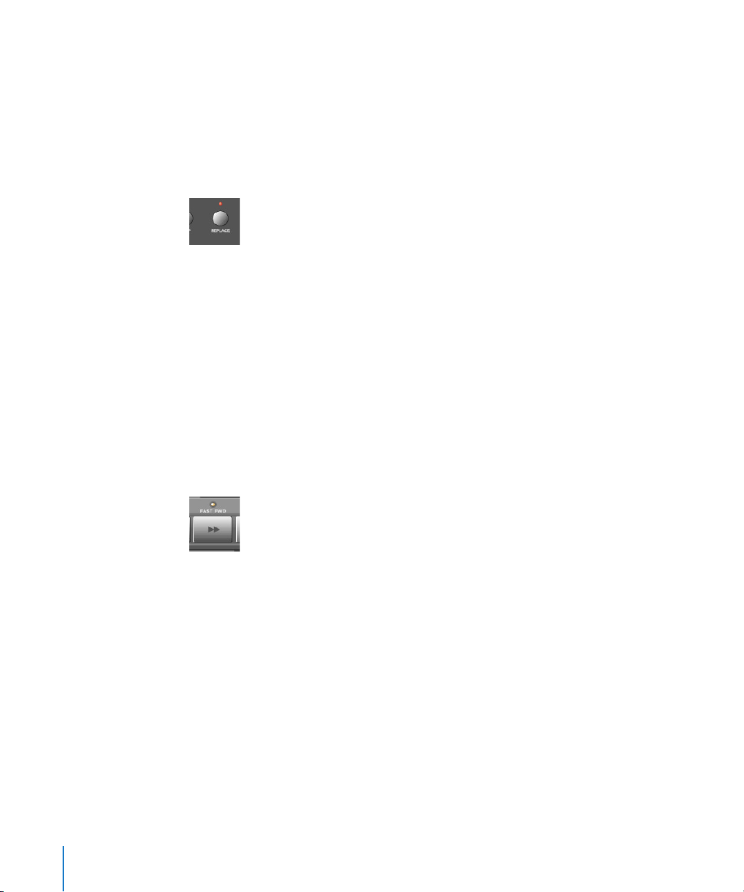
Rewind
Rewinds/shuttles through the song. If pressed repeatedly while rewinding, the rewind
speed will be accelerated with each button push. If the FAST FWD button is pressed
while REWIND is engaged, the fast rewind will be slowed. Repeated presses of the FAST
button will slow down, stop, and eventually reverse the shuttle direction. Pressing
FWD
the STOP button will halt the rewind. Using the JOG/SCRUB WHEEL will also exit shuttle
mode.
When one of the Marker Modes is activated, repeated presses of the REWIND button will
move the Song Position Line (SPL) to the previous marker.
When one of the Nudge Modes is activated, the REWIND button will move the selected
object(s) backward by the value defined in Large Nudge Mode.
Fast Fwd
Fast forwards/shuttles through the song. If pressed repeatedly while fast forwarding,
the shuttle speed will be accelerated with each button push. If the REWIND button is
pressed while FAST FWD is engaged, the fast forward will be slowed. Repeated presses
of the REWIND button will slow down, stop, and eventually reverse the shuttle direction.
Pressing the STOP button will halt the fast forward. Using the JOG/SCRUB WHEEL will also
exit shuttle mode.
When one of the Marker Modes is activated, repeated presses of the FAST FWD button
will move the Song Position Line to the next marker.
When one of the Nudge Modes is activated, the FAST FWD button will move the selected
object(s) forward by the value defined in Large Nudge Mode.
As a tip, you can combine Markers with Cycle regions by pressing the respective
buttons on the Logic Control. This, in conjunction with the “stepping” between markers
mentioned above (using the REWIND and FAST FWD buttons) will move the SPL, and
will automatically set a cycle region between adjacent markers. Try this, and other
options, with various button combinations.
62 Chapter 2 Logic Control—Details
Page 63
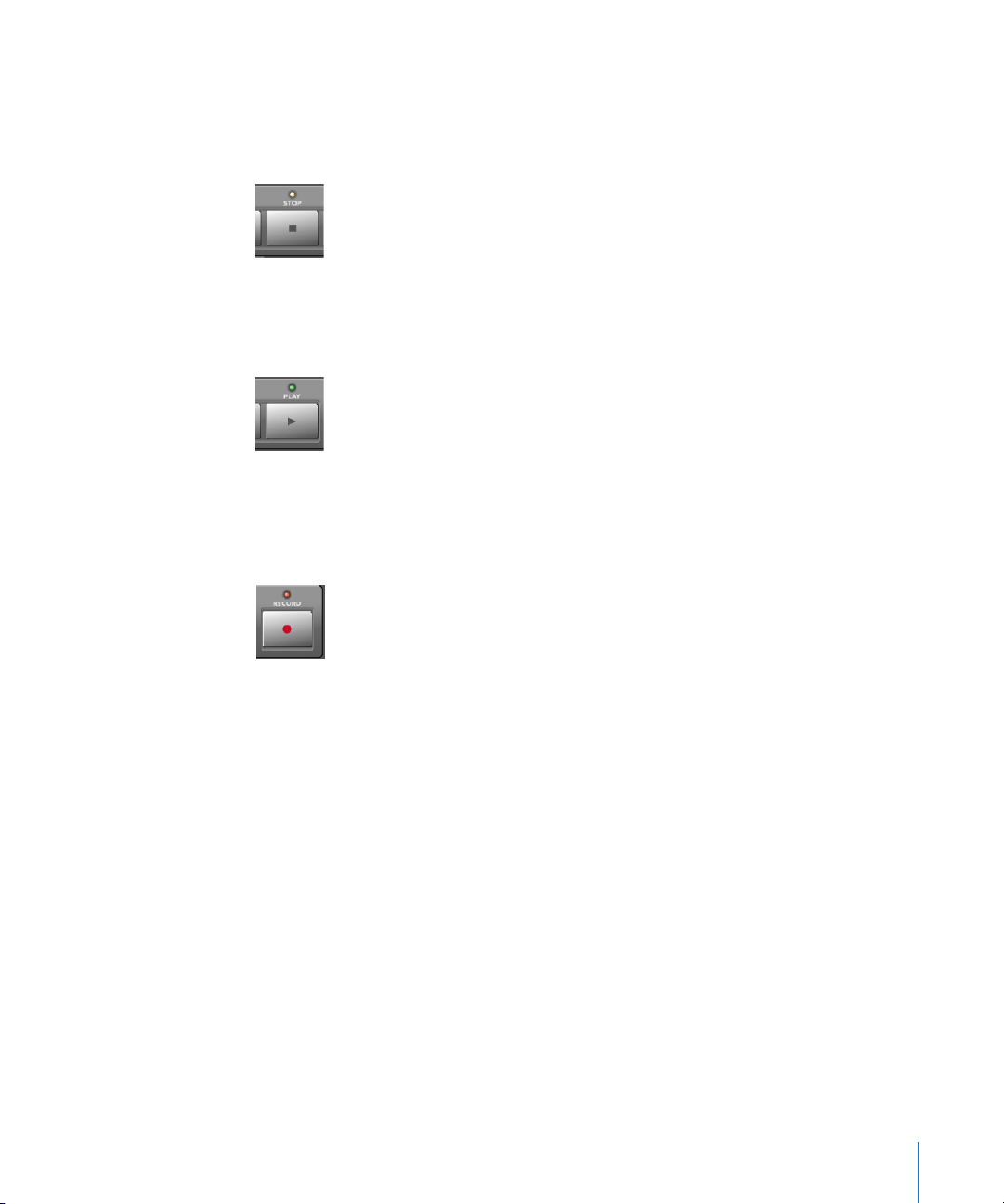
Stop
Stops all other Transport functions. Pressing the STOP button a second time will return
to the song start point, or the beginning of the nearest cycle region, if Cycle is active.
Repeated presses will toggle between the two.
Play
Plays from the current song position. If pressed repeatedly, it will jump to the
beginning of the nearest cycle region, if Cycle is active.
SHIFT + PLAY works as a Pause command.
Record
Activates recording on the selected MIDI, Audio or Audio Instrument track.
A special note for Audio tracks: When the first Audio track is armed by pressing the REC/
RDY
switch on the desired channel, a file save dialog will open on your computer
screen, waiting for you to enter a filename as per usual. The Logic Control LCD will
display There is a file select dialog on the screen and the Position/Time
Display will show
Once the file name has been entered—in Logic—the Logic Control will return all
controls to their status prior to invoking the REC/RDY command.
Once the “default” audio file name has been entered, you may freely select and “arm”
any Audio track, and then press the RECORD button. This will happen without the alert
messages and file save dialog appearing onscreen.
As a general working tip, you should also define a “default” audio file name, after saving
your autoload song under a different name. These should be the first steps when
creating any project.
Chapter 2 Logic Control—Details 63
. All LEDs will go off.
ALErt
Page 64

The Cursor/Zoom Key Zone
This collection of five buttons serves a number of purposes.
Normal operation
When the ZOOM button’s LED is off, these buttons select the current parameter, shift
the current parameter page or Send/EQ/Insert slot, depending on the current V-POT
assignment.
When holding down the OPTION button, the CURSOR LEFT/RIGHT buttons scroll to the
first/last page, and the CURSOR UP/DOWN buttons scroll to the first/last slot.
When holding down the C/ALT button, the CURSOR LEFT/RIGHT buttons shift the
parameter display by only one parameter instead of by one page.
In View modes which don’t need the cursor keys to shift pages or slots, they emulate
the computer keyboard’s cursor keys. Example: Track Multi Channel View.
In Large Nudge Mode and Temporary Nudge Mode, the cursor buttons always emulate
the computer keyboard’s cursor keys. This allows you to easily select an object.
Zoom mode
Pressing the ZOOM button enables Zoom mode. The CURSOR buttons can then be used
to change the vertical or horizontal zoom factor of the active window.
In the Arrange window:
• OPTION and CURSOR UP/DOWN changes the zoom factor of the selected track.
• OPTION and CURSOR LEFT resets the zoom factor of the selected track
• OPTION and CURSOR RIGHT resets the zoom factor of all tracks which are of the same
class (audio, MIDI etc.) as the selected track.
Computer Cursor Key Emulation
To use the cursor buttons as a replacement for the computer keyboard cursor keys,
hold down the
By pressing
mimic the computer cursor keys without the need to hold down
SHIFT key.
SHIFT and ZOOM, the cursor keys go to Permanent Cursor Key Mode, i. e. they
SHIFT. In this mode,
the Zoom button LED flashes.
64 Chapter 2 Logic Control—Details
Page 65

The Jog/Scrub Wheel Zone
The JOG/SCRUB WHEEL and SCRUB button can be used to navigate through the song,
which is useful for a number of Transport tasks. Simply turn the dial to use it. The
following Scrub modes change the behavior of the JOG/SCRUB WHEEL.
• SCRUB mode off: the JOG/SCRUB WHEEL moves the SPL
• SCRUB mode on: the JOG/SCRUB WHEEL performs scrubbing. “Scrubbing” allows you to
hear the data of the selected track while scrolling/moving through the song.
Audio tracks are normally played back with 100% original speed. If you prefer 200%,
choose menu item Audio > Audio Hardware & Drivers, open the DAE section and set
Max. Scrub Speed to Double.
Note: You can also use the SCRUB button for Pause functionality.
• SHUTTLE mode (SCRUB button LED flashing): the JOG/SCRUB WHEEL shuttles the SPL,
i.e. turning it increases or decreases the speed the SPL moves.
Functions and Menus
Channel Strip (x8)
Logic Control Modifier Function/Comments
V-POT
V-SELECT
REC/RDY — Toggle Record Enable of track.
SOLO — Toggle Solo of track.
— Modify parameter displayed in LCD.
OPTION Set parameter to minimum or maximum value.
C/ALT Modify parameter at high resolution.
— Set parameter displayed on LCD to default value, or: Switch between
two possible values.
flashing pre-selection:
— Enter the pre-selected value.
menu options:
— Enter whatever option is visible in display.
If track is folder:
— Enter folder.
OPTION Disable Record Enable for all tracks.
OPTION Disable Solo for all tracks.
In Send Destination/Level Multi Channel View:
— Toggle pre/post status of selected send.
In Send Destination/Level Channel Strip View:
— Toggle pre/post of send on selected track.
Chapter 2 Logic Control—Details 65
Page 66

Logic Control Modifier Function/Comments
MUTE — Toggle Mute of track.
OPTION Disable Mute for all tracks.
In Track Multi Channel View:
SHIFT Toggle Mute/Bypass of the shown parameter
In EQ Multi Channel View:
SHIFT Toggle Bypass of the current EQ band
In EQ Frequency/Gain View:
— Toggle bypass of selected EQ band.
In Send Multi Channel View:
SHIFT Toggle bypass of selected send.
In Send Destination/Level Multi Channel View:
— Toggle bypass of selected send.
In Send Destination/Level Channel Strip View:
— Toggle mute of send on selected track.
In Plug-in Multi Channel View:
SHIFT Toggle bypass of plug-in.
In Instrument Multi Channel View:
SHIFT Toggle bypass of instrument.
SELECT — Select track.
SHIFT Set track volume to unity level (0 dB).
OPTION create a new track with the same instrument of the selected track and
switches to Arrange View
SHIFT+
OPTION
create a new track with the next instrument of the selected track and
switches to Arrange View
66 Chapter 2 Logic Control—Details
Page 67

Logic Control Modifier Function/Comments
FADER — Adjust volume.
In Flip Mode “Duplicate”:
— Same function as
In Flip Mode “Swap”:
— Swap function with
In Surround Angle/Diversity View:
— Adjust surround diversity.
In EQ Frequency/Gain View:
— Adjust gain of selected EQ band.
In Send Destination/Level Multi Channel View:
— Adjust send level of selected send.
In Send Destination/Level Channel Strip View:
— Adjust send level of send on selected track.
V-POT of same channel.
V-POT of same channel.
ASSIGNMENT Section
Hold down to show soft-button menu; release to switch V-POTs to Multi Channel or
Channel Strip views for:
Logic Control Modifier Function/Comments
TRACK — Track parameters
PAN/SURROUND — Pan/Surround parameters
EQ — EQ parameters
SEND — Send parameters
PLUG-IN — Plug-in selection or Plug-in editor
INSTRUMENT — Instrument selection or Instrument editor
BANK
34 — Shift fader bank left/right by number of channel strips.
OPTION Shift fader bank to beginning or end.
CHANNEL
FLIP — Toggle flip mode between “off” and “duplicate”.
GLOBAL VIEW — Toggle between Mixer View and Global View.
34 — Shift fader bank left/right by one channel.
OPTION Shift fader bank to beginning or end.
SHIFT Toggle flip mode between “off” and “swap”.
CONTROL Toggle flip mode between “off” and “zero”
(i.
e. motors off).
SHIFT Toggle between Mixer View and Arrange View.
Chapter 2 Logic Control—Details 67
Page 68

DISPLAY Parameters
Logic Control Modifier Function/Comments
NAME/VALUE — Toggle between parameter name and parameter value display.
SHIFT Cycle through level meter displays: vertical, horizontal and off.
OPTION Toggle between track name and track number:name display.
CONTROL Clear clip/overload flags.
CMD/ALT Enter “Control Surface Group Settings Mode”
SMPTE/BEATS — Toggle between SMPTE and Beat format in clock display.
Function Buttons
Logic Control Modifier Function/Comments
FI — Recall screen set 1.
SHIFT Toggle Arrange window.
CMD/ALT Cut
TRACK Switch to Multi Channel View—Volume.
PAN/
SURROUND
EQ Switch to Multi Channel View—Bypass.
SEND Switch to Multi Channel View—Destination.
MARKER Create Marker without rounding
NUDGE Nudge value: Tick
F2 — Recall screen set 2.
SHIFT Toggle Track Mixer window.
CMD/ALT Copy
TRACK Switch to Multi Channel View—Pan.
PAN/
SURROUND
EQ Switch to Multi Channel View—EQ Type.
SEND Switch to Multi Channel View—Level.
MARKER Create Marker with rounding
NUDGE Nudge value: Format
Switch to Multi Channel View—Pan/surround angle.
Switch to Multi Channel View—Pan/surround radius.
68 Chapter 2 Logic Control—Details
Page 69

Logic Control Modifier Function/Comments
F3 — Recall screen set 3.
SHIFT Toggle Event Editor window.
CMD/ALT Paste
TRACK Switch to Multi Channel View—Track Mode.
PAN/
SURROUND
EQ Switch to Multi Channel View—Frequency.
SEND Switch to Multi Channel View—Position.
MARKER Delete Marker
NUDGE Nudge value: Beat
F4 — Recall screen set 4.
SHIFT Toggle Score window.
CMD/ALT Clear
TRACK Switch to Multi Channel View—Input.
PAN/
SURROUND
EQ Switch to Multi Channel View—Gain.
SEND Switch to Multi Channel View—Mute.
NUDGE Nudge value: Bar
F5 — Recall screen set 5.
SHIFT Toggle Hyper Edit window.
CMD/ALT Select All
TRACK Switch to Multi Channel View—Output.
PAN/
SURROUND
EQ Switch to Multi Channel View—Q Factor.
SEND Switch to Channel Strip View.
NUDGE Nudge value: Frame
F6 — Recall screen set 6.
SHIFT Toggle Matrix Editor window.
CMD/ALT Select All Following
TRACK Switch to Multi Channel View—Automation.
PAN/
SURROUND
EQ Switch to Channel Strip View.
SEND Switch to Channel Strip 2 View.
NUDGE Nudge value: 1/2 Frame
Switch to Multi Channel View—Pan/surround LFE.
Switch to Multi Channel View—Pan/surround mode.
Switch to Channel Strip View.
Switch to Angle/Diversity View.
Chapter 2 Logic Control—Details 69
Page 70

Logic Control Modifier Function/Comments
F7 — Recall screen set 7.
SHIFT Toggle Transport window.
CMD/ALT Select Similar Objects
TRACK Switch to Multi Channel View—Displayed Parameter
PAN/
Switch to Surround X/Y View
SURROUND
EQ Switch to Frequency/Gain Multi Channel View.
SEND Switch to Destination/Level Multi Channel View.
F8 — Close top-most floating window.
SHIFT Toggle Audio window.
CMD/ALT Select Inside Locators
TRACK Switch to Track Setup View.
EQ Switch to Frequency/Gain Channel Strip View.
SEND Switch to Destination/Level Channel Strip View.
GLOBAL VIEW Buttons
Logic Control Modifier Function/Comments
MIDI — Switch to Global View and show MIDI instruments.
SHIFT Set to fader bank no. 1 (e.
INPUTS — Switch to Global View and show audio input objects.
SHIFT Set to fader bank no. 2 (e.
AUDIO TRACKS — Switch to Global View and show audio track objects.
SHIFT Set to fader bank no. 3 (e.
INSTRUMENTS — Switch to Global View and show audio instrument objects.
SHIFT Set to fader bank no. 4 (e.
AUX — Switch to Global View and show aux objects.
SHIFT Set to fader bank no. 5 (e.
BUSSES — Switch to Global View and show bus objects.
SHIFT Set to fader bank no. 6 (e.
OUTPUTS — Switch to Global View and show outputs and master objects.
SHIFT Set to fader bank no. 7 (e.
USER — Currently unassigned.
SHIFT Set to fader bank no. 8 (e.
g. tracks 1 to 8).
g. tracks 9 to 16).
g. tracks 17 to 24).
g. tracks 25 to 32).
g. tracks 33 to 40).
g. tracks 41 to 48).
g. tracks 49 to 56).
g. tracks 57 to 64).
70 Chapter 2 Logic Control—Details
Page 71

MODIFIERS—While Held Down:
SHIFT Switch to second function.
OPTION Apply function to all tracks or set parameter to minimum/maximum.
CONTROL Engage Group Clutch while held down
C/ALT Enable fine mode; shift parameter page by 1 parameter instead of page.
AUTOMATION Buttons
Logic Control Modifier Function/Comments
READ/OFF — Set selected track’s automation to Read or Off.
OPTION Set all tracks’ automation to Read or Off.
TOUCH — Set selected track’s automation to Touch.
OPTION Set all tracks’ automation to Touch.
LATCH — Set selected track’s automation to Latch.
OPTION Set all tracks’ automation to Latch.
WRITE — Set selected track’s automation to Write.
OPTION Set all tracks’ automation to Write.
TRIM Currently unassigned.
GROUP — Enter Group Edit Mode.
SHIFT Create a new group, open the Group window and enter Group Edit
mode
TRACK Switch to Track Multi Channel View, displaying Track Group parameter
UTILITIES Buttons
Logic Control Modifier Function/Comments
SAVE — Save Song.
OPTION Save Song as…
UNDO — Undo.
SHIFT Redo.
OPTION Open Undo History.
CANCEL — Leave folder.
Flashing pre-selection:
— Cancel pre-selection.
In alerts:
— Execute “Cancel” button.
ENTER — Enter folder of selected track.
In alerts:
— Execute default button.
Chapter 2 Logic Control—Details 71
Page 72

TRANSPORT Buttons
Logic Control Modifier Function/Comments
MARKER — Toggle Small Marker Mode.
SHIFT Toggle Large Marker Mode
NUDGE — Toggle Small Nudge Mode.
SHIFT Toggle Large Nudge Mode
MARKER Create a marker. This allows you to create a marker with one hand
without entering “Big Permanent Marker Mode”.
CYCLE — Toggle Cycle.
SHIFT Switch to Cycle View.
DROP — Toggle Drop.
SHIFT Switch to Drop View.
REPLACE — Toggle Replace.
CLICK — Toggle playback or record metronome click.
SHIFT Toggle internal/external sync and MMC.
SOLO — Toggle track solo (of selected track).
SHIFT Enable Solo Lock
REWIND
7 — Shuttle rewind.
MARKER Go to previous marker.
NUDGE Nudge left by chosen value.
CYCLE Engage Cycle and set left locator to SPL.
DROP Engage Drop and set Drop In to SPL.
In Marker Mode:
— Go to previous marker.
In Nudge Mode:
— Nudge left by chosen value.
F.FWD
8 — Shuttle forward.
MARKER Go to next marker.
NUDGE Nudge right by chosen value.
CYCLE Engage Cycle and set right locator to SPL.
DROP Engage Drop and set Drop Out to SPL.
In Marker Mode:
— Go to previous marker.
In Nudge Mode:
— Nudge right by chosen value.
STOP < —Stop.
72 Chapter 2 Logic Control—Details
Page 73

Logic Control Modifier Function/Comments
PLAY 4 —Play.
SHIFT Pause.
RECORD = — Record.
Cursor Keys & Scrub Wheel
Logic Control Modifier Function/Comments
CURSOR
CURSOR
ZOOM — Toggle between default cursor button behavior (see above) and Zoom
SCRUB — Toggle scrub mode
34 If in Multi Channel View:
— Select previous/next parameter or of current View.
ZOOM Scroll window horizontally by page
If in Channel Strip EQ, Send View or Plug-in/Instrument Edit View:
— Shift current editor page by 1 page.
C/ALT Shift current editor page by 1 parameter.
ZOOM Scroll window horizontally by page
Otherwise (always in Nudge mode):
— Mimic computer keyboard cursor left/right keys.
ZOOM Scroll window horizontally by page
In Zoom mode:
— Change horizontal zoom level
SHIFT Reset individual track zoom of current track (Cursor left) or all tracks of
same class (Cursor right)
56 In Channel Strip EQ-, Send View- or Plug-In/Instrument Editor View:
— Select previous/next EQ band, Send or insert slot.
ZOOM Scroll window vertically by page
Otherwise (always in Nudge mode):
— Mimic computer keyboard cursor up/down keys
ZOOM Scroll window vertically by page
In Zoom Mode:
— Change vertical zoom level
SHIFT Change individual track zoom of current track
mode
SHIFT Toggle between default cursor button behavior and permanently
mimicking computer keyboard cursor keys
SHIFT enable Shuttle mode on the Jog Wheel (SCRUB button LED flashes)
Chapter 2 Logic Control—Details 73
Page 74

Logic Control Modifier Function/Comments
JOG WHEEL — Move song position line.
CYCLE Set the Left Locator to the current SPL, advance the SPL as normally,
then set the Right Locator to the SPL. Further Jog Wheel turns while
still holding down CYCLE advances the SPL and sets the Right Locator
again. Tip: rotating the jog wheel counterclockwise while holding
down CYCLE defines a skip-cycle range.
DROP Set the Drop In Locator to the current SPL, advance the SPL as
normally, then set the Drop Oout Locator to the SPL. Further Jog
Wheel turns while still holding down DROP advances the SPL and sets
the Drop out Locator again.
In Scrub Mode (SCRUB button LED on):
— Scrub
In Shuttle Mode (SCRUB button LED flashing):
— Shuttle
External Inputs
Logic Control Modifier Function
USER SWITCH A — Play/Stop
USER SWITCH B — Drop In/Out
EXTERNAL
CONTROL
— Master Volume
74 Chapter 2 Logic Control—Details
Page 75

3 Mackie C4
3
You can use the C4 in an own control surface group (place its icon below Logic Control)
or combined with a Logic Control/XT (place the icon right of the existing icons). In the
latter case, the C4 adds 8 channels in Multi Channel views.
We recommend to use the C4 in an own control surface group. This allows you to edit
instruments and plug-ins and independently do mixing on the Logic Control or other
control surface.
V-POTs, V-SELECTs
The function depends on current view and optional overlay (see below).
The top row (row 1) consists of V-POT/V-SELECT 1 to 8.
Row 2 consists of V-POT/V-SELECT 9 to 16.
Row 3 consists of V-POT/V-SELECT 17 to 24.
The bottom row (row 4) consists of V-POT/V-SELECT 25 to 32.
V-POT/V-SELECT 1 to 8
While no overlay is active, V-POT/V-SELECT 1 to 8 (i.e. the top row) normally do the same
as on a Logic Control or Logic Control XT.
V-POT/V-SELECT 9 to 32
These V-POTs have additional functionality in many views.
In Multi Channel views, the V-POT/V-SELECTs of row 2, 3, and 4 usually edit the
parameter following the parameter edited on row 1.
Example: in Pan Multi Channel view, when row 1 edits Pan/Surround angle, row 2 edits
Surround Diversity, row 3 edits LFE and row 4 edits Surround Mode
In Channel Strip view, all four rows build a group of 32 parameters which can be edited.
In Plug-in and Instrument edit views, it can be split up into two groups (8/24, 16/16 or
24/8 parameters), see below.
75
Page 76

Pan/Surround Multi Channel View:
Row 2 edits Pan/Surround parameter 2
Row 3 edits Pan/Surround parameter 3
Row 4 edits Pan/Surround parameter 4
(in the order Pan/Angle, Diversity, LFE, Surround Mode, X, Y)
SINGLE left/right changes the parameter edited in row 1, and thus also affects the
parameter edited in row 2 to 4
Surround Angle/Diversity View
(to be entered on C4 with CHAN STRIP, V-SELECT 31)
Row 1 edits Surround Angle
Row 2 edits Surround Diversity
Surround X/Y View
(only to be entered from Logic Control)
Row 1 edits Surround X
Row 2 edits Surround Y
Track Multi Channel View
Row 1 edits Track parameter 4
Row 2 edits Track parameter 3
Row 3 edits Track parameter 2
Row 4 edits Track parameter 1, i.e. the parameter edited by V-POTs on a Logic Control or
XT
(in the order Volume, Pan/Angle, Track Mode, Input, Output, Automation Mode, Group,
Displayed Automation Parameter)
The row order is reversed, so that the lowest row editing parameter 1 is closest to the
buttons
BANK left/right and SINGLE left/right change the parameter edited in row 4, and thus
also affects the parameter edited in row 1 to 3
EQ Multi Channel View
Row 1 edits EQ Band Bypass
Row 2 edits EQ Band Frequency
Row 3 edits EQ Band Gain
76 Chapter 3 Mackie C4
Page 77

Row 4 edits EQ Band Q Factor
INSERT up/down selects the edited EQ band
EQ Channel Strip View
Row 1 edits EQ Frequency of all 8 bands
Row 2 edits EQ Gain of all 8 bands
Row 3 edits EQ Q of all 8 bands
Row 4 edits EQ Bypass of all 8 bands
Send Multi Channel View
Row 1 edits Send Destination
Row 2 edits Send Level
Row 3 edits Send Position
Row 4 edits Send Mute
INSERT UP/DOWN selects the edited Send slot
Send Channel Strip View
Rows 1 to 4 edit 32 Send parameters
SINGLE left/right shifts display of Send parameters
Send Channel Strip View 2
Rows 1 to 4 edits 32 Send parameters
SINGLE left/right shifts display of Send parameters
Send Destination/Level View
Row 1 edits Send Destination
Row 2 edits Send Level
Row 3 edits Send Position
Row 4 edits Send Mute
INSERT up/down selects the edited Send slot
Plug-in Select Multi Channel View
INSERT up/down selects the edited plug-in insert
Plug-in Edit View
V-POT/V-SELECT 1 to 32 build a group of 32 parameters. Split is possible.
Chapter 3 Mackie C4 77
Page 78

INSERT up/down selects the edited plug-in insert
BANK left/right shifts the edited parameters by 32. In Split mode, this applies to Split
Upper; when holding down SHIFT: applies to Split Lower
SINGLE left/right shifts the edited parameters by 1. In Split mode, this applies to Split
Upper; when holding down SHIFT: applies to Split Lower
Instrument Edit View
V-POT/V-SELECT 1 to 32 build a group of 32 parameters. Split is possible.
BANK left/right shifts the edited parameters by 32. In Split mode, this applies to Split
Upper; when holding down SHIFT: applies to Split Lower
SINGLE left/right shifts the edited parameters by 1. In Split mode, this applies to Split
Upper; when holding down SHIFT: applies to Split Lower
Buttons at Bottom
SPLIT
Toggles edit split between 4/0, 1/3, 2/2 and 3/1 rows. Edit Split alllows you to edit two
separate sections of a plug-in/instrument or even two different ones.
Split Edit is also possible across multiple C4 units. As an example with two units,
pressing the SPLIT button gets you following split modes:
• 1/7 (i.e. Split Upper is top line of first unit, Split Lower is bottom 3 lines of first unit
and all lines of second unit. LED 1/3 is lit),
• 2/6 (i.e. Split Upper is top 2 lines of first unit, Split Lower is bottom 2 lines of first unit
and all lines of second unit. LED 2/1 is on),
• 3/5 (LED 3/1 is on),
• 4/4 (all 3 LEDs are on),
• 5/3 (all 3 LEDs are on),
• 6/2 (all 3 LEDs are on) and
• 7/1 (all 3 LEDs are on).
LOCK
Toggles Track Lock. When enabled, selecting a track does not switch the currently
selected track
SPOT ERASE
Currently unassigned
MARKER
Toggles between Marker overlay (see below) and normal view
TRACK
Toggles between Track overlay (see below) and normal view
78 Chapter 3 Mackie C4
Page 79

Alternate Mode Options
Holding down the TRACK button accesses a further sub-menu in the bottom LCD to
enter Global View with a certain object type:
• V-SELECT 25 switches to MIDI tracks
• V-SELECT 26 switches to Inputs
• V-SELECT 27 switches to Audio tracks
• V-SELECT 28 switches to Audio Instrument tracks
• V-SELECT 29 switches to Auxiliary tracks
• V-SELECT 30 switches to Busses
• V-SELECT 31 switches to Outputs
• V-SELECT 32 switches to Master output
Releasing the TRACK button without pressing a V-SELECT returns to Mixer View.
CHAN STRIP
Toggles between Channel Strip overlay (see below) and normal view.
Alternate Mode Options
Holding down the
• V-SELECT 25 switches to Pan/Surround Channel Strip
• V-SELECT 26 switches to EQ Channel Strip
• V-SELECT 27 switches to Send Channel Strip
CHAN STRIP button accesses a further sub-menu in the bottom LCD:
FUNCTION
Toggles between Function overlay (see below) and normal view.
Modifier Buttons
SHIFT: as with Logic Control, switches other buttons to alternate function, see “+ SHIFT”
OPTION: as with Logic Control, while held down, parameters are set to minimum/
maximum when edited with V-POT
CTRL
: as with Logic Control, engages the Group Clutch
CMD/ALT: as with Logic Control, while held down, parameters are edited in fine mode
with V-POT
BANK left/right
Shifts parameter display by one page in certain views (see above).
SINGLE left/right
Shifts parameter display by one parameter in certain views (see above).
TRACK L/R
Shifts the currently edited track (in a Channel Strip view) to the previous or next track.
While SHIFT is held down: same, but for Split Lower.
Chapter 3 Mackie C4 79
Page 80

SLOT UP/DOWN
Selects the currently edited EQ, Send or plug-in insert (see above).
Marker Overlay
While the MARKER button light is on, the Marker overlay is active.
A Logic Control in the same control surface group shows “MA” in the assignment
display.
V-SELECT 1 to 30 goes to Marker 1 to 30. The upper LCD line shows the marker name;
the lower line shows “INSIDE” when the song position is inside a marker.
V-SELECT 31 creates a new marker.
V-SELECT 32 deletes the current marker.
Track Overlay
While the TRACK button light is on, the Track overlay is active.
A Logic Control in the same control surface group shows “tr” in the assignment display.
V-SELECT 1 to 32 changes currently edited track. When a track is selected for Split Upper,
the lower LCD line shows “UPPER” for this track. For a track selected for Split Lower,
“LOWER” is shown.
To select a track for Split Upper, press the appropriate V-SELECT.
To select a track for Split Lower, press the V-SELECT while holding down SHIFT. A Logic
Control in the same control surface group shows “tL” in the assignment display.
BANK left/right shifts the fader bank by 32 tracks.
SINGLE left/right shifts the fader bank by 1 track.
Channel Strip Overlay
While the CHAN STRIP button light is on, the Channel Strip overlay is active.
A Logic Control in the same control surface group shows “CS.” in the assignment
display.
V-POT/V-SELECT row 1 edits EQ band 3 to 6 (i.e. the parametric bands’) frequency and
gain.
V-POT/V-SELECT row 2 switches to Plug-in insert 1 to 8 edit.
80 Chapter 3 Mackie C4
Page 81

V-POT/V-SELECT row 3 edits Send 1 to 8 Level.
V-POT/V-SELECT 25 switches to Instrument edit.
V-POT/V-SELECT 26 edits track output.
V-POT/V-SELECT 27 edits automation mode.
V-POT/V-SELECT 28 edits group membership.
V-POT/V-SELECT 29 edits Volume.
V-POT/V-SELECT 30 edits Pan.
V-POT/V-SELECT 31 edits Surround Diversity.
V-POT/V-SELECT 32 edits Track Mode.
Function Overlay
While the FUNCTION button light is on, the Function overlay is active.
A Logic Control in the same control surface group shows “FU” in the assignment
display.
The V-POT/V-SELECTs are predefined with the following assignments:
• 1 (display: “Params”)—toggles the parameter display of the active window
• 2 (“Channl Strip”)—toggles option “Channel Strip Only” in Arrange windows
• 3 (“Delay in ms”)—toggles display of Delays in Milliseconds
• 4 (“Ruler: SMPTE”)—toggles display of time ruler in SMPTE
• 5 (“Global Track”)—toggles display of Global Tracks
• 6 (“Arrang Grid”)—toggles display of the grid in Arrange windows
• 7 (“Event Float”)—toggles display of the Event Floating window
• 8 (“Name/Value”)—switches the display mode between Name and Value (just like the
NAME/VALUE button on the Logic Control)
• 9 (“Track Autom.”)—toggles display of Track Automation in Arrange windows
• 10 (“Trk>Ob Autom.”)—performs key command “Move Current Track Automation
Data To Object”
With the SHIFT button held down (display: “Trk>Ob Au All”), key command “Move All
Track Automation Data To Object” is performed
• 11 (“Ob>Trk Autom.”)—performs key command “Move Current Object Control Data
To Track Automation”
With the SHIFT button held down (display: “Ob>Trk Au All”), key command “Move All
Object Control Data To Track Automation” is performed
Chapter 3 Mackie C4 81
Page 82

• 12 (“Clear Autom.”)—performs key command “Delete currently visible Automation
Data of Current Track”
With the SHIFT button held down (display: “Clear Au All”), key command “Delete All
Automation Data of Current Track” is performed
• 13 (“ClrAll Overld”)—resets the Level Meter Overload displays
• 14 (“ClrAll RecRdy”)—switches off Record Ready for all tracks
• 15 (“ClrAll Solo”)—switches off Solo for all tracks
• 16 (“ClrAll Mute”)—switches off Mute for all tracks
• 17 (“Tool: Arrow”)—chooses the Arrow tool
• 18 (“Tool: Pencil”)—chooses the Pencil tool
• 19 (“Tool: Scissr”)—chooses the Scissors tool
• 20 (“Tool: Glue”)—chooses the Glue tool
• 21 (“Tool: Text”)—chooses the Text tool
• 22 (“Tool: Xfade”)—chooses the Crossfade tool
• 23 (“Tool: Marque”)—chooses the Marquee tool
• 24 (“Tool: Autom.”)—chooses the Automation tool
• V-POT 25 (“WfZoom”)—edits the active Arrange window’s waveform zoom factor
• V-POT 26 (“V.Zoom”)—edits the active window’s vertical zoom factor
• V-POT 27 (“H.Zoom”)—edits the active window’s horizontal zoom factor
• V-POT 28 (“Move Cycle”)—moves the Cycle locators
• V-POT 29 (“Quantz”)—chooses the “Quantize Again” value
V-SELECT 29 performs “Quantize Again” for the selected regions or events
• V-POT 30 (“Format”)—chooses the Format value for clock display
• V-SELECT 31 (“Prev SetEXS”)—performs key command “Next Plug-In Setting or EXS
Instrument”
• V-SELECT 32 (“Next SetEXS”)—performs key command “Previous Plug-In Setting or
EXS Instrument”
Holding down the SHIFT button currently only has V-SELECTs 10 to 12 assigned (see
above); holding down the OPTION, CTRL or CMD/ALT buttons currently contains no
assignments, so you can assign new key commands in these views. Of course you can
also reassign the existing assignments.
82 Chapter 3 Mackie C4
Page 83

Assignment Overview
See also section “Channel Strip (x8)” on page 65.
C4 Modifier Function/Comments
SPLIT — Toggle edit split between 4/0, 1/3, 2/2 and 3/1 rows
LOCK — Toggle Track Lock
SPOT ERASE currently unassigned
MARKER — Toggle between Marker overlay and normal view
TRACK — Toggle between Track overlay and normal view
CHAN STRIP — Toggle between Channel Strip overlay and normal view
FUNCTION — Toggle between Function overlay and normal view
BANK
34 — Shift parameter display by one page in certain views
SHIFT Same, but for Split Lower
SINGLE
34 — Shift parameter display by one parameter in certain views
SHIFT Same, but for Split Lower
TRACK L/R — Shift the currently edited track (in a Channel Strip view) to the
previous or next track
SHIFT Same, but for Split Lower
SLOT UP/DOWN — Select the currently edited EQ, Send or plug-in insert
SHIFT Same, but for Split Lower
Chapter 3 Mackie C4 83
Page 84

Page 85

4 Tascam FW-1884
4
Introduction
Logic supports the Tascam FW-1884 and FE-8 extension.
Version 1.10 also supports the SoftLCD application which displays information on track
names, parameter assignment and current value of the encoders. While one of the
automation mode buttons is held down, SoftLCD displays the tracks’ current
automation mode, and encoder edits it.
Alerts are displayed in SoftLCD. Select buttons allow to remote-control alert buttons.
Requirements
You need
• one or more FW-1884, optionally one or more FE-8
• Logic Pro 7 or Logic Express 7 or newer
Set Up
• Make sure that the FW-1884’s MIDI driver is installed. See the FW-1884
documentation for details
• Connect the FW-1884 using the FireWire cable
• The FW-1884 and FE-8 units are installed automatically.
• If you have multiple units, place their icons in the Setup window left to right so that
they have the same order as the physical units.
Operation
See the Assignment overview section.
The FE-8 extensions only have the Channel Strip section, so the other sections don’t
apply here. The FW-1884 ENCODERS section also applies to the FE-8 channel strips.
85
Page 86

Assignment Overview
A right-aligned modifier button below a button description means: while holding
down this modifier, the button has this alternate meaning.
ENCODERS Section
Control Assignment
FLIP toggles Flip Mode between Off and Swap
PAN assigns Pan to encoders
AUX 1 assigns Send 1 Level to encoders
AUX 2 assigns Send 2 Level to encoders
AUX 3 assigns Send 3 Level to encoders
AUX 4 assigns Send 4 Level to encoders
AUX 5 assigns Send 5 Level to encoders
AUX 6 assigns Send 6 Level to encoders
AUX 7 assigns Send 7 Level to encoders
AUX 8 assigns Send 8 Level to encoders
SHORTCUTS Section
Control Assignment
SAVE/F1 saves the active song. The button’s LED is on when the song has been edited.
REVERT/F2 reverts the active song to the saved version.
ALL SAFE/F3 disables Record Ready for all tracks
CLR SOLO/F4switches Solo off on all tracks
SHIFT switches Mute off on all tracks
MARKERS/F5 creates a new marker at the current song position line
SHIFT deletes the marker at the SPL
LOOP/F6 Toggles Cycle mode
CUT cuts the current selection and puts it in the clipboard
DEL deletes the current selection
COPY copies the current selection to the clipboard
PASTE pastes the clipboard
ALT/CMD Modifier for other buttons. See their description
UNDO performs Undo. The button LED is on when Redo is possible.
SHIFT performs Redo
SHIFT Modifier for other buttons. See their description
CTRL Modifier for other buttons. See their description
86 Chapter 4 Tascam FW-1884
Page 87

Channel strips
Control Assignment
REC LEDs These LEDs are on when the corresponding track is recording and flash when the track
is Record Ready
SEL selects the track
SHIFT when encoders control a Send Level, toggles Send Mute
READ sets the track’s automation mode to Read
WRITE sets the track’s automation mode to Write
TCH sets the track’s automation mode to Touch
LATCH sets the track’s automation mode to Latch
SOLO toggles the Solo status of the track
MUTE toggles the Mute status of the track
Encoder controls parameter chosen with the ENCODERS section
SET when ENCODERS section has chosen Send editing, sets the Send’s destination
Fader controls volume of the track
EQ Section
The EQ controls apply to a certain EQ band of the selected track. A Channel EQ must be
inserted in the track (or the song must use the old, pre 6.0 EQs).
Mode Assignment
REC while held down, the SEL buttons in the channel strips toggle Record Ready status
GAIN edits Gain of currently selected EQ band
SET selects Track input
FREQ edits Frequency of currently selected EQ band
SET selects Track output
Q edits Q factor of currently selected EQ band
SET selects Track mode
HIGH selects parametric EQ band 4 (for Channel EQ)
SHIFT selects High Cut (for Channel EQ)
HI-MID selects parametric EQ band 3 (for Channel EQ)
SHIFT selects High Shelf (for Channel EQ)
LOW-MID selects parametric EQ band 2 (for Channel EQ), or EQ band 4 (for pre-6.0 EQs)
SHIFT selects Low Shelf (for Channel EQ), or EQ band 2 (for pre-6.0 EQs)
LOW selects parametric EQ band 1 (for Channel EQ), or EQ band 3 (for pre-6.0 EQs)
SHIFT selects Low Cut (for Channel EQ), or EQ band 1 (for pre-6.0 EQs)
Chapter 4 Tascam FW-1884 87
Page 88

MASTER fader
This fader always controls the master volume. If no Master object exists in the
environment, it controls Output 1-2.
Master Section
Control Assignment
READ while held down, SEL buttons are on if a track has Read automation mode. Pressing the
SEL button sets Read mode. Turning the encoder also edits the automation mode.
WRITE while held down, SEL buttons are on if a track has Write automation mode. Pressing
the SEL button sets Write mode. Turning the encoder also edits the automation mode.
TCH while held down, SEL buttons are on if a track has Touch automation mode. Pressing
the SEL button sets Touch mode. Turning the encoder also edits the automation mode.
LATCH while held down, SEL buttons are on if a track has Latch automation mode. Pressing
the SEL button sets Latch mode. Turning the encoder also edits the automation mode.
F7 switches encoders to editing of surround parameters on selected track: angle, radius,
LFE, surround mode, X, Y
F8 switches encoders to EQ editing on selected track. For parameter assignment, see
upper line on SoftLCD. Cursor left/right shifts parameter bank.
F9 switches Encoders to plug-in editing on selected track. Cursor left/right shifts
parameter bank; Cursor up/down chooses insert to edit
F10 switches encoders to instrument editing on selected track. Cursor left/right shifts
parameter bank.
Cursor
buttons
SHTL Enables Shuttle mode for Wheel
Wheel Shuttle mode off: moves SPL by bar
Bank LEDs Show currently selected fader bank. With only an FW-1884 installed, a bank means 8
BANK
buttons
LOCATE
buttons
NUDGE
buttons
SET modifier for other buttons. See their description.
IN goes to left locator
like computer keyboard cursor keys; except while encoders are in EQ, plug-in or
instrument editing mode (see above)
SHIFT zooms in and out horizontally or vertically
Shuttle mode on: shuttles SPL
tracks. If you have FE-8 extensions added, a bank means the entire number of channel
strips, e.g. 16, 24 etc.
If no LED is on, a bank higher 4 is selected.
shifts fader bank up or down by one bank
SHIFT shifts fader bank up or down by one track
goes to previous or next marker
nudges the selected objects left or right (by the current nudge value)
SET chooses the current nudge value, in the order Tick, Format, Denominator, Bar, Frame, 1/
2 Frame
88 Chapter 4 Tascam FW-1884
Page 89

Control Assignment
SET sets left locator to current song position
SHIFT sets Drop In locator to current song position
OUT goes to right locator
SET sets right locator to current song position
SHIFT sets Drop Out locator to current song position
REW Shuttle Rewind key command
FFWD Shuttle Forward key command
STOP Stop key command
PLAY Play key command
REC Record key command
Chapter 4 Tascam FW-1884 89
Page 90

Page 91

5 Mackie HUI
Requirements
You need
• a HUI or compatible product
• Logic Pro 7 or newer
Set Up
• Make sure that an XSKey with a Logic Pro 7 authorization is connected.
• Make sure that your HUI unit(s) are connected bidirectionally with the computer,
using a MIDI interface.
• Choose menu item Logic Pro > Control Surfaces > Setup…
• Choose menu item New > Install… in the Setup window’s local menu.
• For every HUI unit, select HUI in the Install window, choose Add, then set the
appropriate MIDI In and Out ports in the Setup window.
5
Other HUI-compatible Devices
If the unit emulates one HUI unit, proceed as if you have a HUI.
If you experience problems in the DSP Edit display, instead install the unit as a DM2000.
If the unit emulates more than one HUI, add an according number of additional devices
in the setup, similarly as for the Yamaha digital mixers. If the unit supports only one HUI
DSP edit section, choose HUI Channel Strips only as the model name for the additional
units. This ensures that scrolling in the DSP edit section scrolls by four parameters.
For the the assignment of the buttons, refer to section Assignment Overview chapter,
from page 92 and the device’s user manual.
91
Page 92

Assignment Overview
A right-aligned modifier button below a button description means: while holding
down this modifier, the button has this alternate meaning.
ASSIGN Section
Control Assignment
SEND A assigns Send 1 Level to
down, the scribble strips show the current Send 1 destination assignment
SHIFT/ADD as above, but Send 6
SEND B assigns Send 2 Level to
down, the scribble strips show the current Send 2 destination assignment
SHIFT/ADD as above, but Send 7
SEND C assigns Send 3 Level to
down, the scribble strips show the current Send 3 destination assignment
SHIFT/ADD as above, but Send 8
SEND D assigns Send 4 Level to
down, the scribble strips show the current Send 4 destination assignment
SEND E assigns Send 5 Level to
down, the scribble strips show the current Send 5 destination assignment
PAN assigns Pan to
s
POT
INPUT assigns Track Input to
Track Input assignment
OUTPUT assigns Track Output to
current Track Output assignment
REC/RDY ALL Disable Record Ready on all tracks
BYPASS toggles the INSERT buttons between Insert Select and Insert Bypass mode
MUTE toggles the
SHIFT toggles Flip mode
SELECT-ASSIGN displays the
Pan, Snd1 to Snd8, S1As to S8As, In, Out
SUSPEND —
DEFAULT toggles
ASSIGN When
mode. Press
V-POTs; assigns selected track’s pan/surround parameters to DSP V-
V-SELECT buttons between Send Position and Send Mute mode
V-POT assignment as follows:
V-SELECT buttons between normal behavior and setting default value
V-POTs display a Send level, switches them to Send Destination assignment
V-SELECT or ASSIGN again to confirm the assignment.
V-POTs, and Send 1 to 4 Levels to DSP V-POTs. While held
V-POTs, and Send 1 to 4 Levels to DSP V-POTs. While held
V-POTs, and Send 1 to 4 Levels to DSP V-POTs. While held
V-POTs, and Send 1 to 4 Levels to DSP V-POTs. While held
V-POTs, and Send 5 to 8 Levels to DSP V-POTs. While held
V-POTs. While held down, the scribble strips show the current
V-POTs. While held down, the scribble strips show the
92 Chapter 5 Mackie HUI
Page 93

Fader Bank Buttons
Control Assignment
Bank Left shifts channel strips by one bank to the left
Bank Right shifts channel strips by one bank to the right
Channel Left shifts channel strips by one channel to the left
Channel Right shifts channel strips by one channel to the right
WINDOW Section
Control Assignment
TRANSPORT toggles the Transport window
EDIT toggles the Arrange window
MIX toggles the Track Mixer window
ALT toggles the Sample Editor window
STATUS toggles the Audio Pool window
MEM-LOC toggles the Marker List window
KEYBOARD SHORTCUTS Section
Control Assignment
UNDO performs undo
SHIFT/ADD performs redo
OPTION/ALL opens undo history window
SAVE saves the song
OPTION/ALL Save As…: saves the song with a different name
EDIT MODE —
EDIT TOOL selects the next tool. While held down, digit buttons select a specific tool
SHIFT/ADD Shifts to second meaning of some buttons
See also description of other buttons
OPTION/ALL While held down, value change mode is set to “full”: relative value changes to go
minimum or maximum
See also description of other buttons
CTRL/CLUTCH While held down, the Group Clutch is engaged, i.e. all groups are disabled
CMD/ALT/FINE While held down, value change mode is set to “fine”: relative value changes work
with maximum resolution
See also description of other buttons
Chapter 5 Mackie HUI 93
Page 94

Channel Strips
Control Assignment
Level Meters display momentary and peak level
REC/RDY toggles Record Ready
OPTION/ALL disables Record Ready for all tracks
INSERT BYPASS off: selects track for plug-in selection
BYPASS on: toggles bypass of currently selected insert slot
V-SEL Pan selected: sets Pan to center if DEFAULT on
Send 1 to 8 selected: edits Send Pre/Post, toggles Send Mute or sets Send Level to
default value
Send Assign, Input or Output: confirms selection
V-POT adjusts parameter selected in the ASSIGN section
AUTO cycles automation mode.
With an automation mode button held down, sets this automation mode
SOLO toggles Solo
OPTION/ALL disables Solo for all tracks
MUTE toggles Mute
OPTION/ALL unmutes all tracks
Scribble Strip displays track name, or Send, In or Out assignment
SELECT selects track
SHIFT/ADD Sets volume to unity level
DEFAULT Sets volume to unity level
Fader adjusts volume, or duplicates
V-POT in Flip mode
94 Chapter 5 Mackie HUI
Page 95

DSP EDIT/ASSIGN Section
Control Assignment
ASSIGN —
COMPARE toggles DSP display between modes “track name/parameter name” and “parameter
name/parameter value”
BYPASS toggles bypass of currently edited plug-in insert
DSP Select 1 to 4Assignment Pan:
• DSP Select 1 sets Pan or Surround Angle to center
• DSP Select 2 sets Surround Diversity to center
• DSP Select 3 sets Surround LFE to center
• DSP Select 4 sets Surround Mode to center
Assignment Send:
• toggle Send 1 to 4 or 5 to 8 Mute
Plug-In Assign:
• confirm insert 1 to 4 or 5 to 8 plug-in selection, selects this insert and enters Plug-
In Edit mode
Plug-In Edit:
• sets value to default, or toggles switch
DSP
V-POTs Assignment Pan:
• DSP V-POT 1 controls Pan or Surround Angle
• DSP V-POT 2 controls Surround Diversity
• DSP V-POT 3 controls Surround LFE
• DSP V-POT 4 controls Surround Mode
Assignment Send:
• control Send 1 to 4 or 5 to 8 Level
Plug-In Assign:
• assigns insert 1 to 4 or 5 to 8 plug-in
Plug-In Edit:
• sets value to default
INSERT/PARAM toggles between Plug-in Assign and Plug-in Edit modes
SCROLL Plug-In Edit: shifts parameter display by the number of DSP
surface group (usually four)
CMD/ALT/FINE Plug-In Edit: shifts parameter display by one
V-POTs in the control
Chapter 5 Mackie HUI 95
Page 96

Function Keys
Control Assignment
F1 Clears Overload LEDs
SHIFT/ADD Switches to Global View and enables MIDI Tracks
CMD/ALT/FINE Toggles Arrange window
F2 Recalls Screen Set 2
SHIFT/ADD Switches to Global View and enables Inputs
CMD/ALT/FINE Toggles Track Mixer window
F3 Recalls Screen Set 3
SHIFT/ADD Switches to Global View and enables Audio Tracks
CMD/ALT/FINE Toggles Event Editor window
F4 Recalls Screen Set 4
SHIFT/ADD Switches to Global View and enables Audio Instruments
CMD/ALT/FINE Toggles Score Editor window
F5 Recalls Screen Set 5
SHIFT/ADD Switches to Global View and enables Aux Tracks
CMD/ALT/FINE Toggles Hyper Editor window
F6 Recalls Screen Set 6
SHIFT/ADD Switches to Global View and enables Busses
CMD/ALT/FINE Toggles Matrix Editor window
F7 Toggles counter display between SMPTE and bars/beats/format/ticks
SHIFT/ADD Switches to Global View and enables Outputs and Master object
CMD/ALT/FINE Toggles Transport window
F8/ESC Default: leaves folder
Goto Marker: cancels dialog
CMD/ALT/FINE Toggles Audio window
AUTO ENABLE Section
Control Assignment
FADER toggles automation playback and recording of Volume
PAN toggles automation playback and recording of Pan
PLUG IN toggles automation playback and recording of Plug-in parameters
MUTE toggles automation playback and recording of Mute
SEND toggles automation playback and recording of Send Level
SEND MUTE —
96 Chapter 5 Mackie HUI
Page 97

AUTO MODE Section
Control Assignment
READ sets selected track to automation mode “Read”. While held down, channel Strip
AUTO buttons set automation mode to Read
OPTION/ALL sets all tracks to automation mode “Read”
LATCH sets selected track to automation mode “Latch”. While held down, channel Strip
AUTO buttons set automation mode to “Latch”
OPTION/ALL sets all tracks to automation mode “Latch”
TRIM —
TOUCH sets selected track to automation mode “Touch”. While held down, channel Strip
AUTO buttons set automation mode to “Touch”
OPTION/ALL sets all tracks to automation mode “Touch”
WRITE sets selected track to automation mode “Write”. While held down, channel Strip
AUTO buttons set automation mode to “Write”
OPTION/ALL sets all tracks to automation mode “Write”
OFF sets selected track to automation mode “Off”. While held down, channel Strip AUTO
buttons set automation mode to “Off”
OPTION/ALL sets all tracks to automation mode “Off”
STATUS/GROUP Section
Control Assignment
AUTO while held down, the Scribble Strips display the tracks’ automation mode
MONITOR —
PHASE —
GROUP enters Group Edit mode:
• the upper line in the DSP edit section displays the currently edited group number
and name
• DSP Select buttons 1 to 4 toggle properties of the currently edited group, labelled
in the lower line
• When INSERT/PARAM is off, DSP Edit Scroll V-POT scrolls through the group
properties. Otherwise it selects the currently edited group
• the SELECT buttons toggle group membership of the track
SHIFT/ADD switches to Track View
CREATE creates a new group and enters Group Edit mode (see above)
SHIFT/ADD switches to Global View
SUSPEND toggles the Group Clutch
SHIFT/ADD switches to Extended Track View
Chapter 5 Mackie HUI 97
Page 98

EDIT Section
Control Assignment
CAPTURE —
SEPARATE —
CUT Cuts the selection
COPY Copies the selection
PASTE Pastes the clipboard contents
DELETE Deletes the selection
Time Display
Control Assignment
TIME CODE checked if counter displays time code
FEET (not assigned)
BEATS checked if counter displays bars/beats/format/ticks
Time display displays time code or bars/beats/format/ticks
RUDE SOLO
LIGHT
flashes if any track is soloed
98 Chapter 5 Mackie HUI
Page 99

LOCATE/NUMBERS Section
Control Assignment
CLR Deletes current marker
= Creates a marker at the current song position
/ equivalent to computer keyboard / key
* equivalent to computer keyboard * key
- equivalent to computer keyboard – key
+ equivalent to computer keyboard + key
0 to 9 Normal: 1 to 9 recalls marker 1 to 9
Goto Marker: equivalent to computer keyboard keys 0 to 9
SHIFT/ADD Switches to Global View and enables
1: MIDI Tracks
2: Inputs
3: Audio Tracks
4: Audio Instruments
5: Aux Tracks
6: Busses
7: Outputs and Master object
9:
0:
EDIT TOOL selects tool:
1: arrow
2: pencil
3: rubber
4: text edit
5: scissors
6: glue
7: solo
8: mute
9: zoom
0 Goto Marker: equivalent to computer keyboard 0 key
. Normal: enters Goto Marker Mode
Goto Marker: confirms entered marker number
ENTER Normal: enters folder of selected track
Goto Marker: confirms entered marker number
Chapter 5 Mackie HUI 99
Page 100

Transport Section
Control Assignment
AUDITION —
PRE Sets left locator
IN Sets Drop In locator
OUT Sets Drop Out locator
POST Sets right locator
RTZ goes to the left locator
END goes to the right locator
ON LINE toggles internal/external Sync
LOOP toggles Cycle mode
QUICK PUNCH toggles Drop mode
REWIND Shuttles backward
FAST FWD Shuttles forward
STOP Stop
PLAY Play
SHIFT/ADD Pause
RECORD Record
100 Chapter 5 Mackie HUI
 Loading...