

Page 1
10
22
+20
OO
U
1
LEVEL
+20
OO
U
2
+20
OO
U
3
LEVEL
+20
OO
U
4
STEREO AUX RETURNS
AUX RETURN
TO CONTROL
ROOM ONLY
SOURCE
ALT 3-4
40
30
20
10
7
4
2
0
2
4
7
+
–
CLIP
PHONES
OO
SOLO
+20
OO
U
TAPE
MONITOR
LEVEL
POWER
LM-3204 STEREO LINE MIXER
,,,
,
,
,
,
,
,
,
,,,,
,
,
,
,,
,
,
,
,,
,
,
,
,
,
,,
,
,,
,
dB
20
15
5
10
OO
5
10
30
40
U
dB
20
15
5
10
OO
5
10
30
40
U
,
,
,
,
,
,
,
,,
,,
,
,
,
,
,,,
,,
,
,
,,
,
,,,
,
,
,
,
,,
,
,,
,
,,
,
,
,,
,
,
,
,
,
,
,
,
,
,,,
,
,
,,
,
,
,
,,
,
,
,
,,
LEFT RIGHT CONTROL R M
U
+30dB
OO
BALANCE
L
–15 +15
U
–12 +12
U
2
+15
OO
U
–15 +15
U
1
+15
OO
U
1
SHIFT
-20
OL
4
3
12k
STEREO
MONO
HI
80
LO
2.5k
MID
EQ
SOLO
AUX
LR
U
+30dB
OO
BALANCE
L
–15 +15
U
–12 +12
U
2
+15
OO
U
–15 +15
U
1
+15
OO
U
2
SHIFT
-20
OL
4
3
12k
STEREO
MONO
HI
80
LO
2.5k
MID
EQ
SOLO
AUX
LR
U
+30dB
OO
BALANCE
L
–15 +15
U
–12 +12
U
2
+15
OO
U
–15 +15
U
1
+15
OO
U
3
SHIFT
-20
OL
4
3
12k
STEREO
MONO
HI
80
LO
2.5k
MID
EQ
SOLO
AUX
LR
U
+30dB
OO
BALANCE
L
–15 +15
U
–12 +12
U
2
+15
OO
U
–15 +15
U
1
+15
OO
U
4
SHIFT
-20
OL
4
3
12k
STEREO
MONO
HI
80
LO
2.5k
MID
EQ
SOLO
AUX
LR
U
+30dB
OO
BALANCE
L
–15 +15
U
–12 +12
U
2
+15
OO
U
–15 +15
U
1
+15
OO
U
5
SHIFT
-20
OL
4
3
12k
STEREO
MONO
HI
80
LO
2.5k
MID
EQ
SOLO
AUX
LR
U
+30dB
OO
BALANCE
L
–15 +15
U
–12 +12
U
2
+15
OO
U
–15 +15
U
1
+15
OO
U
6
SHIFT
-20
OL
4
3
12k
STEREO
MONO
HI
80
LO
2.5k
MID
EQ
SOLO
AUX
LR
U
+30dB
OO
BALANCE
L
–15 +15
U
–12 +12
U
2
+15
OO
U
–15 +15
U
1
+15
OO
U
7
SHIFT
-20
OL
4
3
12k
STEREO
MONO
HI
80
LO
2.5k
MID
EQ
SOLO
AUX
LR
U
+30dB
OO
BALANCE
L
–15 +15
U
–12 +12
U
2
+15
OO
U
–15 +15
U
1
+15
OO
U
8
SHIFT
-20
OL
4
3
12k
STEREO
MONO
HI
80
LO
2.5k
MID
EQ
SOLO
AUX
LR
U
+30dB
OO
BALANCE
L
–15 +15
U
–12 +12
U
2
+15
OO
U
–15 +15
U
1
+15
OO
U
9
SHIFT
-20
OL
4
3
12k
STEREO
MONO
HI
80
LO
2.5k
MID
EQ
SOLO
AUX
LR
U
+30dB
OO
BALANCE
L
–15 +15
U
–12 +12
U
2
+15
OO
U
–15 +15
U
1
+15
OO
U
10
SHIFT
-20
OL
4
3
12k
STEREO
MONO
HI
80
LO
2.5k
MID
EQ
SOLO
AUX
LR
U
+30dB
OO
BALANCE
L
–15 +15
U
–12 +12
U
2
+15
OO
U
–15 +15
U
1
+15
OO
U
11
SHIFT
-20
OL
4
3
12k
STEREO
MONO
HI
80
LO
2.5k
MID
EQ
SOLO
AUX
LR
U
+30dB
OO
BALANCE
L
–15 +15
U
–12 +12
U
2
+15
OO
U
–15 +15
U
1
+15
OO
U
12
SHIFT
-20
OL
4
3
12k
STEREO
MONO
HI
80
LO
2.5k
MID
EQ
SOLO
AUX
LR
U
+30dB
OO
BALANCE
L
–15 +15
U
–12 +12
U
2
+15
OO
U
–15 +15
U
1
+15
OO
U
13
SHIFT
-20
OL
4
3
12k
STEREO
MONO
HI
80
LO
2.5k
MID
EQ
SOLO
AUX
LR
U
+30dB
OO
BALANCE
L
–15 +15
U
–12 +12
U
2
+15
OO
U
–15 +15
U
1
+15
OO
U
14
SHIFT
-20
OL
4
3
12k
STEREO
MONO
HI
80
LO
2.5k
MID
EQ
SOLO
AUX
LR
U
+30dB
OO
BALANCE
L
–15 +15
U
–12 +12
U
2
+15
OO
U
–15 +15
U
1
+15
OO
U
15
SHIFT
-20
OL
4
3
12k
STEREO
MONO
HI
80
LO
2.5k
MID
EQ
SOLO
AUX
LR
U
+30dB
OO
BALANCE
L
–15 +15
U
–12 +12
U
2
+15
OO
U
–15 +15
U
1
+15
OO
U
16
SHIFT
-20
OL
4
3
12k
STEREO
MONO
HI
80
LO
2.5k
MID
EQ
SOLO
AUX
LR
1
CHANNEL
2
CHANNEL
3
CHANNEL
4
CHANNEL
5
CHANNEL
6
CHANNEL
7
CHANNEL
8
CHANNEL
9
CHANNEL
10
CHANNEL
11
CHANNEL
12
CHANNEL
13
CHANNEL
14
CHANNEL
15
CHANNEL
16
CHANNEL
MUTE
ALT 3-4
MUTE
ALT 3-4
MUTE
ALT 3-4
MUTE
ALT 3-4
MUTE
ALT 3-4
MUTE
ALT 3-4
MUTE
ALT 3-4
MUTE
ALT 3-4
MUTE
ALT 3-4
MUTE
ALT 3-4
MUTE
ALT 3-4
MUTE
ALT 3-4
MUTE
ALT 3-4
MUTE
ALT 3-4
MUTE
ALT 3-4
MUTE
ALT 3-4
GAINGAINGAINGAINGAINGAINGAINGAINGAINGAINGAINGAINGAINGAINGAINGAIN
®
LM-3 204 O WNER ’S MANU AL
Page 2
CAUTION AVIS
RISK OF ELECTRIC
DO NOT OPEN
RISQUE DE
CAUTION: TO REDUCE THE RISK OF ELECTRIC SHOCK
DO NOT REMOVE COVER (OR BACK)
NO USER-SERVICEABLE PARTS INSIDE
REFER SERVICING TO QUALIFIED PERSONNEL
ATTENTION: POUR EVITER LES RISQUES DE CHOC
ELECTRIQUE, NE PAS ENLEVER LE COUVERCLE. AUCUN
ENTRETIEN DE PIECES INTERIEURES PAR L'USAGER. CONFIER
L'ENTRETIEN AU PERSONNEL QUALIFIE.
AVIS: POUR EVITER LES RISQUES D'INCENDIE OU
D'ELECTROCUTION, N'EXPOSEZ PAS CET ARTICLE
The lightning flash with arrowhead symbol within an equilateral
triangle is intended to alert the user to the presence of uninsulated
"dangerous voltage" within the product's enclosure, that may be
of sufficient magnitude to constitute a risk of electric shock to persons.
Le symbole éclair avec point de flèche à l'intérieur d'un triangle
équilatéral est utilisé pour alerter l'utilisateur de la présence à
l'intérieur du coffret de "voltage dangereux" non isolé d'ampleur
suffisante pour constituer un risque d'éléctrocution.
The exclamation point within an equilateral triangle is intended to
alert the user of the presence of important operating and maintenance
(servicing) instructions in the literature accompanying the appliance.
Le point d'exclamation à l'intérieur d'un triangle équilatéral est
employé pour alerter les utilisateurs de la présence d'instructions
importantes pour le fonctionnement et l'entretien (service) dans le
livret d'instruction accompagnant l'appareil.
CHOC
NE PAS OUVRIR
A LA PLUIE OU A L'HUMIDITE
SHOCK
ELECTRIQUE
SAFETY INSTRUCTIONS
1. Read Instructions — Read all the safety and operation
instructions before operating the LM-3204 Console.
2. Retain Instructions — Keep the safety and operating
instructions for future reference.
3. Heed Warnings — Follow all warnings on the LM-3204
Console and in these operating instructions.
4. Follow Instructions — Follow all operating and other
instructions.
5. Water and Moisture — Do not use the LM-3204 Console
near water - for example, near a bathtub, washbowl, kitchen
sink, laundry tub, in a wet basement, near a swimming pool,
swamp or salivating St. Bernard dog, etc.
6. Heat — Locate the LM-3204 Console away from heat
sources such as radiators, compost pits or other devices that
produce heat.
7. Power Sources — Connect the LM-3204 Console only to
a power supply of the type described in these operation
instructions or as marked on the LM-3204 Console.
8. Power Cord Protection — Route power supply cords so
that they are not likely to be walked upon or pinched by
items placed upon or against them, paying particular
attention to cords at plugs, convenience receptacles, and the
point where they exit the LM-3204 Console.
9. Object and Liquid Entry — Do not drop objects or spill
liquids into the inside of the LM-3204 Console.
10. Damage Requiring Service — The LM-3204 Console
should be serviced only by qualified service personnel when:
A. LM-3204 Console power-supply cord or the plug has
been damaged; or
B. Objects have fallen, or liquid has spilled into the LM3204 Console; or
C. The LM-3204 Console has been exposed to rain; or
D. The LM-3204 Console does not appear to operate or
exhibits a marked change in performance; or
E. The LM-3204 Console has been dropped, or its chassis
damaged.
11. Servicing — Do not attempt to service the LM-3204
Console beyond those means described in this operating
manual. All other servicing should be referred to the Mackie
Tech SupportDepartment.
13. To prevent electric shock, do not use the LM-3204
Console polarized plug with an extension cord, receptacle or
other outlet unless the blades can be fully inserted to prevent
blade exposure.
Pour préevenir les chocs électriques ne pas utiliser cette fiche
polariseé avec un prolongateur, un prise de courant ou une
autre sortie de courant, sauf si les lames peuvent être
insérées à fond sans laisser aucune pariie à découvert.
14. Grounding or Polarization — Do not defeat the
grounding or polarization of the LM-3204 Console.
This apparatus does not exceed the Class A/Class B
(whichever is applicable) limits for radio noise emissions
from digital apparatus as set out in the radio interference
regulations of the Canadian Department of Communications.
ATTENTION —Le présent appareil numérique n’émet pas de
bruits radioélectriques dépassant las limites applicables aux
appareils numériques de class A/de class B (selon le cas)
prescrites dans le règlement sur le brouillage radioélectrique
édicté par les ministere des communications du Canada.
WARNING — To reduce the risk of fire or electric shock, do
not expose this appliance to rain or moisture.
v1.1–10/94
2
©1994, Mackie Designs, All Rights Reserved.
Printed in the USA.
Page 3
PLEASE! SAVE THE
SHIPPING BOX!
T op Ten Reasons for
saving your shipping box:
10. It’s here.
9. It’s yours.
8. It’s paid for .
7. It’s strong and sturdy.
6. It fits your mixer perfectly.
5. You will need it if you ever ship your mixer.
4. We may have to sell you another one if you
need to ship your mixer and you don’t have
it.
3. It will impress your friends who have no
lives when they see it in your basement.
2. It’s the ecologically sound thing to do.
1. It’s the Mackie sound thing to do.
Top Ten Reasons for
shipping box:
10. Your cat has alr eady used it.
9. You stole the mixer out of a Karaoke bar.
8. Your Mackie mixer will never br eak.
7. You will never move again.
6. You wrote a song on it and ar e considering
framing it.
5. You have cut off the top and ar e using it as
an equipment rack.
4. You r eally hate planning ahead because it
never works out anyway.
3. It fits some other manufacturer’s product,
which is broken, perfectly.
2. You have kept all the boxes of all the other
equipment you have ever bought and you
have never used one of them ever .
1. You ar e afraid of corrugated products.
not
saving your
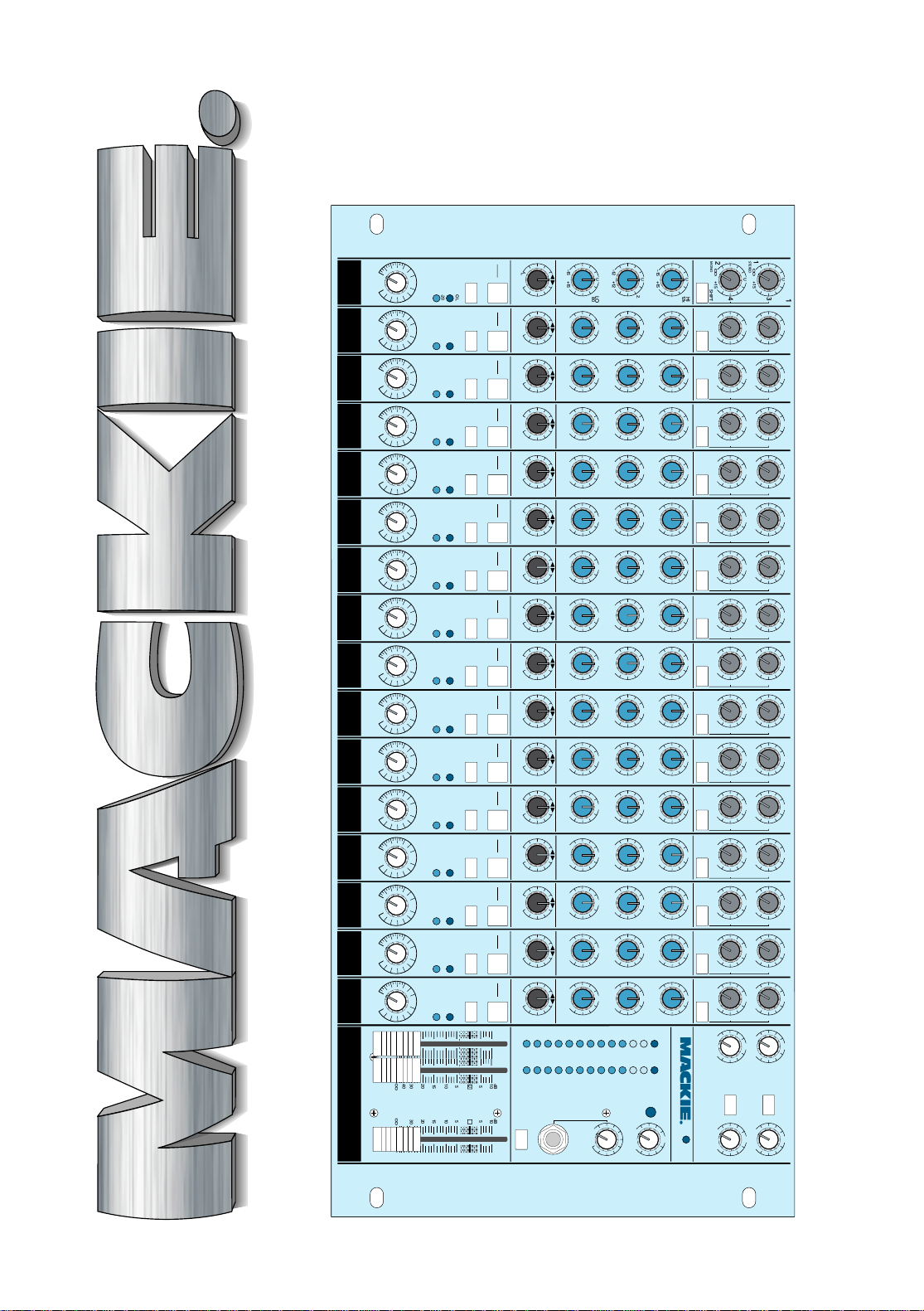
P ANEL LA YOUT AND
FUNCTION
GENERAL
INFORMA TION
USING THE
LM-3204
CONNECTIONS, OPTIONS,
SPECS, AND SER VICE
T ABLE OF CONTENTS
SECTION 1:
Introduction..................................................... 4
Sensitivity Adjustments.................................... 5
SECTION 2:
Panel Layout & Function.................................. 6
Input module (channel strip).................. 6
Master output section................................ 9
Rear Panel ................................................12
SECTION 3:
General Information........................................16
SECTION 4:
Using the LM-3204 ..........................................19
Instrument submixer, stage.....................19
Instrument submixer, studio...................20
Effects submixer, studio ...........................20
Main mixer, studio...................................20
Club sound reinforcement mixers...........20
Other applications....................................21
APPENDIX A:
Connections ....................................................30
APPENDIX B:
Options, Add-Ons and Extra Stuff ...................33
APPENDIX C:
Specifications, Tech Stuff................................34
APPENDIX D:
Service ............................................................38
LAYOUT
AND
FUNCTION
GENERAL
INFO
USING THE
LM-3204
APPENDICES
3
Page 4

SECTION 1: INTRODUCTION
The Mackie LM-3204 is a 32-input, 2+2 Bus
line level sound mixer. Each of the 16 stereo input modules is fitted with gain, balance, EQ and
auxiliary send controls.
The LM-3204 is designed for applications requiring control of a number of stereo/mono line
level sources, while providing exceptional audio
performance in a small (and very affordable)
rack-mounted unit — it makes the ideal centerpiece of a MIDI project suite.
The LM-3204 is equally suited for use as a
synthesizer/sampler/effects submixer for stage,
sound reinforcement and studio applications.
The LM-3204 is also perfect for audio-visual
sound mixing in exhibit halls and in presentation rooms, for multiple-source architectural
sound distribution, and for simple audio and video
post-production suites.
IF YOU IGNORE MANUALS...
How did you find this section?
Because you’re secretly wondering if there
might actually be something worth your time in
a book like this. What can we say? We’ll give you
concise, accurate information that even relates
to the real world, some nice patching diagrams,
a bit of entertainment and a full year’s worth of
weather forecasts for 7 regions of the country.
Why, we’r e even thinking of drilling a hole in the
corner so you can hang it by the toilet.
If you’re moving too fast to review all this
great prose, try to check out Section 2 and the
system Block Diagram. There are a few handy
and/or unique features in the LM-3204 design
you should know about.
At the very least, look for this important icon:
It marks information that is absolutely critical or
is unique to the LM-3204.
In addition, sections tagged with this icon:
include both in-depth information and our own
deeply felt but never biased opinions.
Note: one of the icons in the manual is actually a scratch-off icon, which, if you rub long
enough with the edge of a coin, will make a hole
in the page. If you succeed in finding a secret
message under a Mackie icon, please write us
and tell us about it. (W e wer e going to make another industry first and put a scratch-and-sniff
icon in this manual, but our Odors and Pheromones Department could not find a smell
related to sound mixing that was not in some
way offensive.)
4
Page 5

IMPOR T ANT SENSITIVITY
ADJUSTMENT PROCEDURE!
So important we put it first, before anything
else.
To fully achieve the LM-3204 Mixer’s
impressive headroom and specs, you should
always “tune” the input sensitivity for each
channel.
FOLLOW THIS PROCEDURE FOR EACH
CHANNEL IN USE
1. Set the Control Room, Phones, Left and Right
Master Fader and Solo controls all the way
off. (As you are working through the steps,
you can bring these controls up a bit to hear
what you are doing, but be careful. Ther e’s a
lotta level in this mixer .)
2. Apply signal to channel input.
Insert a stereo line input into the corresponding Left and Right Input jacks at the rear of
the mixer .
or
Insert a mono line input into the corresponding Left Input jack on the rear of the mixer.
3. Set channel strip controls as follows:
Gain control at “U” detent.
Solo switch down.
Mute switch up.
Balance control at “U” detent.
EQ controls at “U” detent.
Aux controls fully counterclockwise (off).
4. Apply an audio signal to the input. The
material and level you use to set up the mixer
should be vaguely representative of what you
will really be doing when you really do it. If
you’re connected to a tape deck or a CD
player , put some music on and push the
button! If you’re hooked up to a synthesizer ,
tickle those plastic ivories!
5. The channel’s –20dB LED should light. The
L/R main meters will show the actual
internal operating level of soloed signals.
Now you will optimize levels.
For a meter reading of 0d Bu w ith + 4dBu
input (line level) signals, the settings in step 3
should be just about right. Adjust the channel
Gain control slightly so that you get peaks that
regularly hit 0dB on the Left and Right meters.
For –10dBV signals, you may have to turn
the channel Gain control clockwise to
boost the signal to r ead 0d B on
the Left and Right meters.
On the other hand, you might have to deviate
from this approach on certain channels. For
example, you don’t want to set the hi-hat cymbal
channel at 0dB. Use your judgement on this.
The Long Arm Exercise: For Microphone
signals (using an onboard Mackie mic
preamp), leave the channel Gain setting at
the “U” detent and instead adjust the Mic
Trim pot on the r ear of the mixer until you
get peak levels of around 0dB on the Left and
Right meters. Remember , the sound coming
in the microphone should be typical of what
you will really be using. For patching instructions, see page 11, “Microphone
Preamplifiers.”
6. If desired (optional):
Adjust the channel strip’s EQ to about what
you will be using during the session.
Repeat Step 5.
7. Return the channel strip’s Solo button to the
up position.
8. Repeat steps 1–7 on the next channel that is
being used.
9. As you un-solo the channel strips to listen to
your mix, ease up the Left and Right master
faders to set a good mix level on the meters,
with occasional peaks of 0dB.
5
Page 6
1
E
N
OO
STEREO
2
OO
MONO
AUX
–15 +15
–12 +12
–15 +15
LR
L
BALANCE
MUTE
ALT 3-4
SOLO
CHANNEL
16
OO
GAIN
SECTION 2: P ANEL LA YOUT & FUNCTION
16
U
3
+15
U
4
+15
SHIFT
ON THE LEFT SIDE
Most of the LM-3204 front panel (four-fifths,
precisely) is occupied by the 16 stereo, line
level input modules or channel strips. Each
strip sports identical features, functions, knobs
and buttons, so we’ll take a close look at one
HI
U
12k
and leave it to you to extrapolate. Still with us?
ON THE RIGHT SIDE
U
MID
2.5k
The rightmost one-fifth of the LM-3204 is
the Master Output section, featuring auxiliary
U
GAIN
EQ
returns, master level controls, meters, lights
LO
80
and a few other tricks.
THE OFFICIAL GUIDED TOUR OF A
TYPICAL LM-3204 INPUT MODULE
(CHANNEL STRIP)
Pretty straightforward. But remember,
these are all stereo input modules, so even
though there is only one volume control and
one EQ section per channel strip, there are
OL
actually two audio channels, Left and Right,
-20
routed through each strip…so each control
U
+30dB
on an input module is a dual control, working
on both sides of the stereo signal.
1
STEREO
2
MONO
AUX
1
U
3
OO
+15
U
4
OO
+15
SHIFT
HI
U
12k
1
STEREO
2
MONO
AUX
2
U
U
3
1
OO
+15
U
STEREO
OO
U
4
2
OO
+15
U
SHIFT
OO
MONO
AUX
HI
U
12k
+15
+15
THE GAIN CONTROL
At the bottom of each strip is the white Gain
knob, which is a stereo gain control for that
channel’s signal. In the time-honored Mackie
tradition, the Gain control has a tremendous
range, from off at the
or loss of gain) to a 30dB increase in signal level
when fully clockwise providing 15dB of gain
above unity. This range allows the LM-3204 to
easily handle a wide range of “line level” inputs,
from professional +4dBu and +8dBu levels all
the way down to consumer and semi-pro-type –
10dBV levels and lower .
to or subtracted from the input signal. With
the input Gain control and Left/Right master
gain controls set at “U,” a –10dBV signal at
the input jacks of the LM-3204 is still –10 at
the output jacks. Likewise, a +4dBu signal
comes in at +4 and goes out at +4.
SHIFT
3
3
4
HI
12k
1
STEREO
2
MONO
AUX
4
U
U
3
1
OO
+15
U
STEREO
OO
+15
U
4
2
OO
+15
U
SHIFT
OO
+15
MONO
AUX
HI
U
12k
“ ” mark to unity (no gain
The “U” mark at the top
center the Gain control’s
arc of travel stands for
“Unity Gain.” It’s the point
at which no level is added
SHIFT
5
3
4
HI
12k
1
STEREO
2
MONO
AUX
6
U
3
OO
+15
U
4
OO
+15
SHIFT
HI
U
12k
1
STEREO
2
MONO
AUX
7
U
3
OO
+15
U
4
OO
+15
SHIFT
HI
U
12k
1
STEREO
2
MONO
AUX
8
U
3
OO
+15
U
4
OO
+15
SHIFT
HI
U
12k
9
U
U
3
1
STEREO
1
OO
+15
U
STEREO
OO
+15
U
4
2
MONO
AUX
2
OO
+15
U
SHIFT
OO
+15
MONO
AUX
HI
U
12k
–15 +15
U
–12 +12
U
–15 +15
EQ
LR
L
BALANCE
MUTE
ALT 3-4
SOLO
CHANNEL2CHANNEL3CHANNEL4CHANNEL5CHANNEL6CHANNEL7CHANNEL8CHANNEL9CHANNEL10CHANNEL
1
OO
6
–15 +15
U
MID
2.5k
–12 +12
U
LO
80
–15 +15
EQ
LR
L
BALANCE
MUTE
ALT 3-4
SOLO
OL
-20
U
OO
+30dB
–15 +15
U
MID
2.5k
–12 +12
U
LO
80
–15 +15
EQ
LR
L
BALANCE
MUTE
ALT 3-4
SOLO
OL
-20
U
OO
+30dB
–15 +15
MID
2.5k
–12 +12
LO
80
–15 +15
EQ
LR
L
BALANCE
MUTE
ALT 3-4
SOLO
OL
-20
U
OO
+30dB
–15 +15
U
U
U
+30dB
U
MID
2.5k
–12 +12
U
LO
80
–15 +15
EQ
LR
L
BALANCE
MUTE
ALT 3-4
SOLO
OL
-20
OO
–15 +15
U
MID
2.5k
–12 +12
U
LO
80
–15 +15
EQ
LR
L
BALANCE
MUTE
ALT 3-4
SOLO
OL
-20
U
OO
+30dB
–15 +15
U
MID
2.5k
–12 +12
U
LO
80
–15 +15
EQ
LR
L
BALANCE
MUTE
ALT 3-4
SOLO
OL
-20
U
OO
+30dB
–15 +15
U
MID
2.5k
–12 +12
U
LO
80
–15 +15
EQ
LR
L
BALANCE
MUTE
ALT 3-4
SOLO
OL
-20
U
OO
+30dB
–15 +15
U
MID
2.5k
–12 +12
U
LO
80
–15 +15
EQ
LR
L
BALANCE
MUTE
ALT 3-4
SOLO
OL
-20
U
OO
+30dB
GAINGAINGAINGAINGAINGAINGAINGAINGAIN
–15 +15
U
MID
2.5k
–12 +12
U
LO
80
–15 +15
EQ
L
L
BALANC
MUTE
ALT 3-4
SOLO
OL
-20
U
+30dB
U
OO
GAI
Page 7
To make matters even easier, the crack Mackie
,
,
,
,,,,,,,
,
,
,
,
,
,
O
Detent Crew have put a little mechanical “pothole” or detent at the Unity Gain point on every
rotary control. Adding detents is a precise, tedious
and largely thankless job, so think of those guys
every now and then as you’re going about your
glamorous and exciting lives mixing and recording
and performing, while they work late into the
night in rainy W oodinville with their little bags of
punches and elf-sized ball-peen hammers.
THE LEDs
Above the Gain knob are two LED (light-emitting diode) indicator lights to help you monitor
the signal levels within each input module.
–20 LED
The green LED is marked –20. It will light
whenever there is a signal level of –20dBu (at
1kHz) or above at the input jacks of that channel strip. In practice, this LED will flicker or
light almost constantly when there is activity in
that channel, and it basically serves as a convenient indicator for you — a way of figuring out
who’s singing now or what’s plugged into wher e.
Whether it lights rarely or is on all the time
is not really important; it’s just a porch light to
10
U
3
+15
U
4
+15
SHIFT
X
HI
U
12k
5+15
U
MID
2.5k
+12
U
LO
80
+15
EQ
R
LANCE
E
-4
O
OL
NNEL11CHANNEL12CHANNEL13CHANNEL14CHANNEL15CHANNEL16CHANNEL
-20
0
U
+30dB
1
OO
STEREO
2
OO
MONO
AUX
–15 +15
–12 +12
–15 +15
LR
L
BALANCE
MUTE
ALT 3-4
SOLO
OO
11
U
3
+15
U
4
+15
SHIFT
HI
U
12k
U
MID
2.5k
U
LO
80
EQ
OL
-20
U
+30dB
1
STEREO
2
MONO
AUX
–15 +15
–12 +12
–15 +15
BALANCE
MUTE
ALT 3-4
SOLO
OO
U
OO
+15
U
OO
+15
U
U
U
EQ
LR
L
U
SHIFT
+30dB
12
3
4
HI
12k
MID
2.5k
LO
80
OL
-20
1
OO
STEREO
2
OO
MONO
AUX
–15 +15
–12 +12
–15 +15
LR
BALANCE
MUTE
ALT 3-4
SOLO
OO
13
U
3
+15
U
4
+15
SHIFT
HI
U
12k
U
MID
2.5k
U
LO
80
EQ
L
OL
-20
U
+30dB
1
STEREO
2
MONO
AUX
–15 +15
–12 +12
–15 +15
BALANCE
MUTE
ALT 3-4
SOLO
OO
U
OO
+15
U
OO
+15
U
U
U
EQ
LR
L
U
SHIFT
+30dB
14
3
4
HI
12k
MID
2.5k
LO
80
OL
-20
1
STEREO
2
MONO
AUX
–15 +15
–12 +12
–15 +15
BALANCE
MUTE
ALT 3-4
SOLO
OO
U
OO
+15
U
OO
+15
U
U
U
EQ
LR
L
U
SHIFT
+30dB
15
3
1
STEREO
4
2
MONO
AUX
HI
12k
MID
2.5k
LO
80
BALANCE
MUTE
ALT 3-4
SOLO
OL
-20
OO
OO
–15 +15
–12 +12
–15 +15
EQ
LR
L
OO
GAINGAINGAINGAINGAINGAINGAIN
show you somebody’s home. We designed it to
be ultra-responsive, so, with a little practice,
you can probably tell what’s on the channel (or
at least the difference between the kick drum
channel and a keyboard channel). However, it’s
not the way to determine levels. There is a
much more accurate way to measure your input strip levels: see the section on Setting
Levels in Solo further down the pike here.
Note: The –20 LED shows
signal activity on the right
side of each channel. If you
had a stereo source (two
cords, two plugs) or a mono
source (one plug into the left MONO jack), the
–20 LED will reflect that signal. However, if you
have a stereo source with no signal happening
on the right side, the –20 LED will be as unresponsive as a hybernating hippo on Sominex
OL LED
The red LED is marked OL, and that stands
for OverLoad. The channel strip OverLoad circuits constantly check at two critical points in
the input module: after the line input’s first gain
amplifier and after the EQ and gain circuits. If
either circuit is driven too hard (into overload),
16
U
U
3
1
OO
+15
U
+20
U
4
2
OO
+15
U
U
U
U
+30dB
+20
SHIFT
LEVEL
HI
12k
LM-3204 STEREO LINE MIXER
22
+
MID
OL
-20
10
2.5k
LO
80
–
,,,,,,
,,,,,,
,,,,,,
7
4
2
0
2
4
7
10
20
30
40
STEREO AUX RETURNS
,,,,,
,,,,,
,,,,,
LEFT RIGHT CONTROL R M
CLIP
AUX RETURN
TO CONTROL
ROOM ONLY
dB
10
5
U
5
10
15
20
30
40
OO
SOURCE
ALT 3-4
PHONES
dB
10
5
U
5
10
15
20
30
40
OO
U
OO
+20
U
OO
LEVEL
POWER
U
OO
+20
SOLO
OO
LEVEL
TAPE
MONITOR
,,,,,
,,,,,
,,,,,
3
4
+20
LA YOUT
AND
FUNCTION
16
U
3
1
OO
+15
STEREO
U
4
2
OO
+15
MONO
SHIFT
AUX
HI
U
12k
™
.
–15 +15
–12 +12
–15 +15
LR
L
BALANCE
MUTE
ALT 3-4
SOLO
CHANNEL
16
OO
GAIN
U
MID
2.5k
U
LO
80
GAIN
EQ
OL
-20
U
+30dB
7
Page 8
1
OO
STEREO
2
OO
MONO
AUX
–15 +15
–12 +12
–15 +15
LR
L
BALANCE
MUTE
ALT 3-4
SOLO
CHANNEL
16
OO
GAIN
the red OL light will flash.
This is to be avoided. Overloading a mixer cir-
16
U
+15
U
+15
U
cuit forces the audio signal to clip and seriously
3
distort the sound. When the OL light flashes, it
means something is too loud. It could be the
level of the unit connected to the LM-3204 input
4
jacks or a device you plugged into the Insert
SHIFT
Jack; maybe you have the Gain control turned
too high or an extreme amount of EQ (which
HI
12k
lifts the gain in certain frequency ranges). You
need to find out what is too loud and turn it
U
MID
down until the OL LED no longer lights.
2.5k
Note: When a channel
strip is soloed, both the
U
LO
80
GAIN
EQ
channel LEDs light
steadily to indicate that
module’s solo status.
SOLO
A solo function on a mixer allows you to listen to (and on a Mackie mixer, to observe on
the meters) any input or combination of inputs without affecting the main or auxiliary
OL
outputs of the mixer. In other words, you can
-20
push a solo button to check something out
U
+30dB
just about any time without affecting your
recording or sound reinforcement feed.
The Solo switch on each LM-3204 channel
strip assigns the stereo signal in that channel
to the stereo solo buses. Both the channel –20
will also light that pulsating flambeau, that impudent alarm, that ruby pharos guarding the
Mackie shore, the Rude Solo Light.
MUTE/ALT 3–4
Next up is the Mute switch, which lives up to
its name by muting its channel strip. When the
Mute switch is depressed, the signal in that input module is removed from the main Left/Right
buses and from any selected Auxiliary buses.
Even though the channel is muted, there
can still be audio within the input module. The
–20 and OL lights will light, signal will still be
available at the Insert jack (channels 1–4),
and the channel Solo function will still work. In
regard to the main and auxiliary outputs,
though, the channel is effectively turned off.
But there is a twist.
IMPORTANT: Any and all muted channels
are routed to an additional pair of stereo outputs, called the Alt 3–4 outputs. If you have
nothing connected to Alt 3–4 outputs, the
Mute switch is simply a Mute switch. If you
use Alt 3–4, then the Mute switch acts like an
assignment button, switching the signal between two sets of stereo output buses: the
Main L–R and the Alt 3–4 buses. This feature
is fraught with potential. What appeared at
first as a two-bus mixer now is revealed to be,
for many purposes, a four-bus mixer. Yow!
LED and OL LED will light steadily to indicate
the module’s solo status. The solo signals are
tapped off after the Balance control, the Gain
control and the EQ circuits, and will be affected by all these settings.
IMPORTANT!! Setting Levels with Solo
BALANCE
What looks like a pan pot, acts like a pan pot but
is not a pan pot? It’s a Balance control! With a stereo input module, you are no longer dealing with a
mono signal to pan from left to right. Instead, you
have a stereo signal already spread across the
On the LM-3204, Solo has another impor-
tant function.
Each Solo switch also triggers circuitry
that disconnects the meters, the Control
Room monitors and the Phones from their
normal duties and reconnects them all to the
output of the solo buses. Not only can you listen to the soloed tracks but you can measure
them on the 13-segment main meters.
In fact, this is the recommended way to ad-
just input levels. As you are initially setting up
a stereo pair of inputs, push the Solo button. It
doesn’t matter if the channel strip is muted:
solo will function on a muted or unmuted
track. Now set the input level to the range you
want, simply by checking out the main meters.
Lastly, by means of extr emely expensive state-
soundstage, and you may have to only tweak the
balance between the two channels a bit.
That’s what the Balance control on the
LM-3204 does. It’s identical to the balance
control on your Aunt Agatha’s Unrealistic hi-fi
receiver. There is a detent at the top, where
the balance is even. As you shift the control
from one side to the other, the stereo balance
changes, with the extremes being left channel
only or right channel only.
Note: It is possible to use a channel strip
on the LM-3204 as a mono input by plugging a
cord only into the Left (MONO) input. In this
case, the mono signal is applied equally to
both of the stereo signal paths. In this mode,
the Balance control acts just like a pan pot,
automatically! What a world we live in.
of-the-art highly obfuscated envelope-pushing
silicon technology, any Solo switch on the board
8
Page 9
EQ
,
,
,
,
,
,
,
,
,
In keeping with the stereo theme of this entire
mixer , the engineers at Mackie have decided to
provide stereo equalization as well. Just like the
stereo Gain control, the EQ knobs have both left
and right EQ sections ganged on a single shaft.
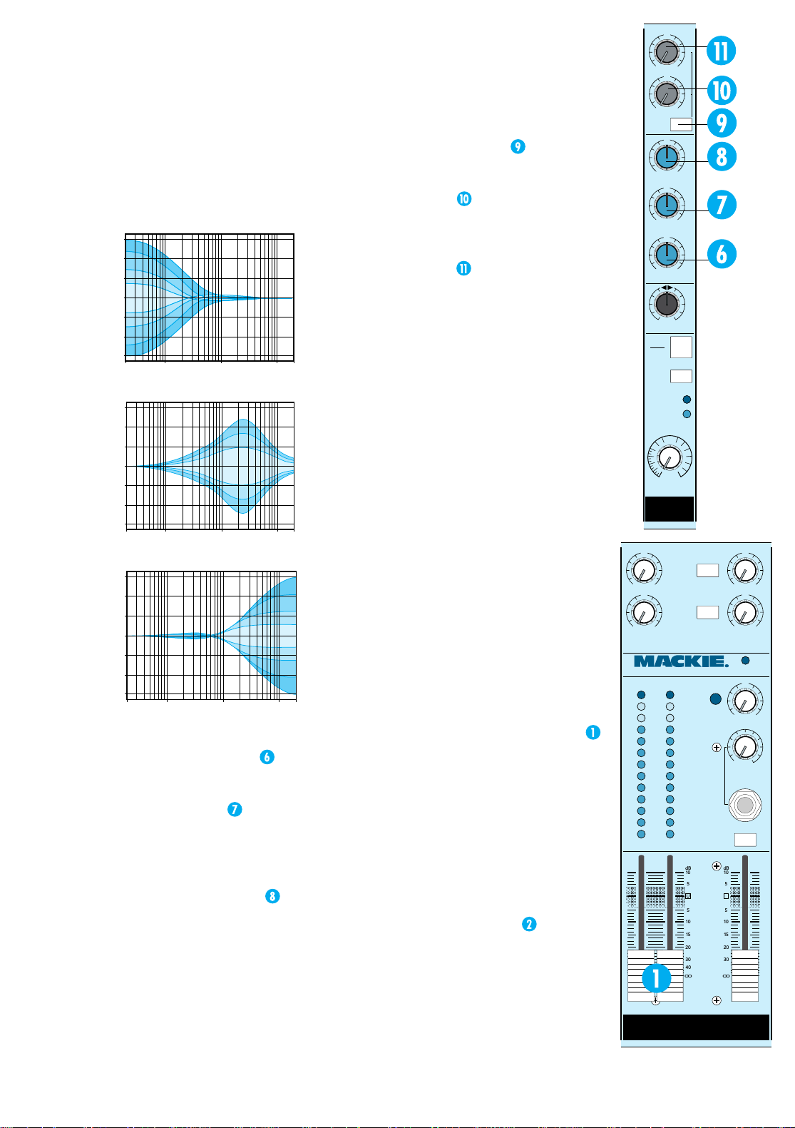
The LM-3204 EQ has three sections, each
with a fixed knee or center frequency and
bandwidth. Frequency curves are shown below.
+15
+10
+5
0
–5
–10
–15
20
Hz
100
Hz
LM-3204 Lo shelving EQ ±15dB boost/cut.
+15
+10
+5
0
–5
–10
–15
20
Hz
100
Hz
LM-3204 Mid peaking EQ ±12dB boost/cut.
+15
+10
+5
0
–5
–10
–15
20Hz 100Hz 1kHz 10kHz 20kHz
LM-3204 Hi shelving EQ ±15dB boost/cut.
The low-frequency equalizer
ing EQ with the knee of the shelf set at 80 Hz.
The Lo section offers a swing of ±15dB.
The mid-frequency EQ
featuring a bell-shaped peak/dip curve centered at 2.5 kHz with a smooth-sounding
2-octave bandwidth. The Mid section can cut
or boost over a range of ±12dB.
The high-frequency equalizer
ing EQ with the knee of the shelf set at 12
kHz. Like the Lo section, the Hi section offers
a swing of ±15dB at a very useful frequency.
When any of the EQ knobs are set at their
“Unity” detents, that section is effectively out
of the circuit.
1k
Hz
1k
Hz
10kHz20k
10kHz20k
is a peaking EQ,
Hz
Hz
is a shelv-
is a shelv-
AUX SENDS
The LM-3204 offers 4 separate sets of auxiliary sends from each input module. Two sets
of sends per module can be selected at any
one time. The Shift switch
allows you to
choose either sends 1 and 2, or sends 3 and 4
on any channel strip.
Sends 1 and 3
, selected alternately by
the Shift button, are true stereo sends with
left and right channels maintained separately
throughout the auxiliary send circuitry.
Sends 2 and 4
, also selected alternately
by the Shift switch, are mono sends. Within
each channel strip, the left and right input
signals are combined into a mono sum for
sends 2 and 4, which appear at their output
jacks as monaural signals.
All the sends on the LM-3204 are post-Gain
control, post-EQ, post-Mute switch. Unfortunately, due to the incredibly dense surface
mount circuitry inside this beast, modifications are not possible.
Each AUX send control has a “Unity” detent at the top of its travel, and, like the rest
of the mixer, will deliver a “level in = level
out” signal at the send outputs when set to
“U.” Setting the aux send controls fully clockwise delivers a whopping +15dB of gain.
THE MASTER OUTPUT SECTION —
THE TOUR CONTINUES
The Master Output section is that right-hand
one-fifth of the LM-3204 we promised we’d talk
about earlier in the manual. This section is
home to the Master Faders, Control Room,
Headphone and Solo level controls, the AUX Returns and, of course, the Rude Solo Light.
LEFT AND RIGHT MASTER FADERS
The mix level of the main Left and Right
buses is controlled by the Left and Right
Master Faders. The unity gain point for the
mix output circuits is marked with a “U,”
with 10dB of gain available beyond that
point. When both channel strip Gain and
the Left and Right Master Faders are set at
unity, the output level of the LM-3204 will
be the same as the input level.
LEFT AND RIGHT METERS
Above the Master Faders are the Left
and Right Meters. These are peak averaging meters, with zero (0)dB referenced to
16
U
3
1
OO
+15
STEREO
U
4
2
OO
+15
MONO
SHIFT
AUX
HI
U
12k
–15 +15
U
MID
2.5k
–12 +12
U
LO
80
GAIN
–15 +15
EQ
LR
L
BALANCE
MUTE
ALT 3-4
SOLO
OL
CHANNEL
-20
16
U
OO
+30dB
GAIN
U
1
OO
+20
U
2
OO
+20
LEVEL
LM-3204 STEREO LINE MIXER
22
+
10
7
4
2
0
2
4
7
10
20
30
–
40
,,,,,,
,,,,,,
,,,,,,
SOURCE
ALT 3-4
AUX RETURN
TO CONTROL
ROOM ONLY
STEREO AUX RETURNS
CLIP
dB
10
5
,,,,,
U
,,,,,
,,,,,
5
10
15
20
30
40
OO
PHONES
MONITOR
dB
10
5
,,,,,
U
,,,,,
,,,,,
5
10
15
20
30
40
OO
OO
OO
LEVEL
POWER
OO
SOLO
OO
LEVEL
TAPE
LEFT RIGHT CONTROL R M
U
3
+20
U
4
+20
U
+20
9
Page 10
U
,
,
,
,
,
,
,
,
,
1
OO
+20
U
2
OO
+20
LEVEL
LM-3204 STEREO LINE MIXER
22
+
10
7
4
2
0
2
4
7
10
20
30
–
40
,,,,,,
,,,,,,
,,,,,,
LEFT RIGHT CONTROL R M
SOURCE
ALT 3-4
AUX RETURN
TO CONTROL
ROOM ONLY
STEREO AUX RETURNS
CLIP
dB
10
5
,,,,,
U
,,,,,
,,,,,
5
10
15
20
30
40
OO
PHONES
dB
10
5
U
5
10
15
20
30
40
OO
OO
OO
POWER
OO
OO
MONITOR
,,,,,
,,,,,
,,,,,
0dBu (.775 volts rms) at the rear output
jacks. The LM-3204’s main outputs are
0dBu=0dB Meter whether you are using
balanced or unbalanced cables.
The meters are switched by the same circuits
that switch the Control Room and Phones monitors. So whatever you are hearing in the monitors
is what’s on the meters. Normally , that would be
the main Left and Right bus outputs. If the T ape
Monitor switch is pushed down, the meters (and
the monitors) are connected to the T ape In jacks.
(See the Tape Monitor switch note in the Monitor ing section a little farther on.)
NOTE: The Control
Room fader does not affect
meter levels.
And remember, whenever
any solo button is pressed,
the meters are not reading the main output bus
level. When a Solo button is pressed, the monitors and the meters are connected to the solo
buses for input level adjustment.
Y ou should set your L/R levels for a r eading in
the middle of the meters, with occasional peaks
reaching into the yellow +7 to +10 range. You
should never have the levels loud enough to light
the red OL LEDs, which are set at +20dBu, just
U
U
before clipping (+22dBu) to indicate
bus distortion.
3
+20
STEREO AUX RETURNS
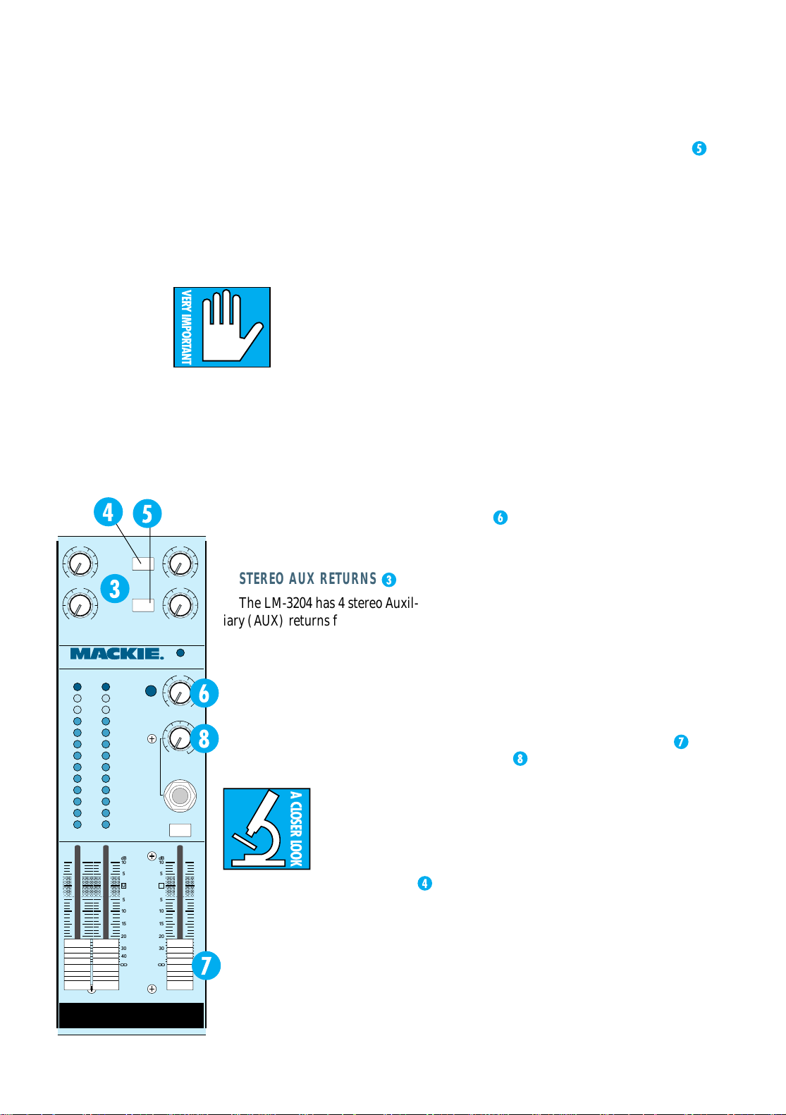
The LM-3204 has 4 stereo Auxil-
4
+20
LEVEL
iary (AUX) returns for reverb, delay
and other effect returns. The returns
pass through ganged stereo level con-
U
trols and are routed into the main
Left and Right buses. Each level con-
+20
SOLO
trol has a “U” detent and plenty of
gain (+20dB) for any effect you use.
Just like a channel strip input, any
LEVEL
return can be used in mono by patching into the Left input only.
There are a
TAPE
couple of Mackie bonus switches in the
AUX Return circuits:
THE SOURCE ALT 3–4 SWITCH
This switch works on the AUX
Return 3. With the switch up, AUX
Return 3 is just what it’s advertised
to be: an AUX Return. When the
Source Alt 3–4 switch is down, AUX
Return 3 inputs are disconnected.
Instead, the outputs of the Alt 3–4
buses are routed into the AUX
Return 3 control and circuitry.
This allows you to use Alt 3–4 as a pair of
submix buses and then re-mix them back into
the main Left and Right buses.
AUX RETURN TO CONTROL ROOM ONLY
It has such a long name that it hardly
needs any explanation. When this switch is
up, AUX Return 4 functions normally. When
the switch is down, the AUX Return 4 is disconnected from the main Left and Right buses
and is re-connected to the control room monitor and headphone circuits (where it is mixed
back in with Left and Right signal on its way
to the Monitor section).
This allows you to use wet monitor, listen-
ing with echo or delay without actually using
the effect in the main Left and Right outputs,
or to “play along” to a cue or click feed without having it go onto tape.
SOLO
When a Solo button is pressed, the soloed
signals are sent to the meters and the solo
buses, which are fed to the control room
monitor and headphone circuits. The Solo
control
in the main Output section sets
solo monitoring level. It has no effect on the
levels on the meters or on any of the main, alternate or auxiliary buses.
Next to the Solo level control is the Rude
Solo Light, as nasty an indicator as our Indicator Department could find without
actually being dangerous. When it is blinking, something is soloed. Simplicity itself.
Furthermore, the –20 and OL LEDs on soloed
channel(s) glow steadily to indicate Solo-ed status.
MONITORING
The LM-3204 has both Control Room
and Phone monitoring outputs, each circuit with its own level control. Monitoring
controls consist of the stereo Control Rm
fader, the Phones level control (with a handy
Phones jack just below it), and the Tape
Monitor switch.
Control Rm and Phone monitor outputs
always share the same sources:
• The main Left and Right buses under
normal conditions;
• The output of your tape recorder (or some
other source patched into the Tape In jacks)
when the Tape Monitor switch is pushed, or;
• The stereo solo buses whenever any Solo
switch is pressed. The solo circuits override
the Tape Monitor switch.
10
Page 11

Quick recap: In the up position, the Tape
Monitor switch selects the main Left and
Right bus outputs for the monitor circuits and
the meters. In the down position, the Tape
Monitor switch selects the Tape Inputs for the
monitor circuits and the meters.
MICROPHONE PREAMPLIFIERS
Another Mackie bonus feature! How did
this come about? Was there just too much
blank space on the back panel? Did somebody say, “Well, what if you have a
microphone?” We’ll never know. But the
happy fact is, in addition to all the fabulous
stereo line input features you could possibly
want, there are two high-performance
Mackie microphone preamplifiers hidden
away on the rear panel, just in case you need
them.
The mic preamps each have a standard
XLR-3 input connector, a trim control, and
switchable phantom powering. However, they
don’t go anywhere (non-normalled). That’s up
to you.
To use a mic preamp, simply patch one of
1
the (unbalanced
one of the line input jacks of the mixer. Patch
’em in mono, patch ’em in stereo, patch ’em
anywhere your cord will reach.
⁄4") Mic Out jacks into any
NOTE: While dynamic
mics ignore phantom
power, ribbon mics don’t.
Make sure that the Phantom Power switch is off
before plugging in a ribbon mic. Wouldn’t
®
want to barbecue your Beyer
The
Long Arm Exercise
The mic Trim knob will add from +10dB
to +50dB of sensitivity to an LM-3204 input.
For proper level setting, put all the controls
in your signal path at the “U” detent and
solo the input module you are using for a
mic input. Then, while someone is making
appropriate noises in front of the microphone, adjust the mic trim so that the peak
levels read about 0dB on the meters.
If you are using condenser microphones,
don’t forget to engage the Phantom Power
switch, located between the two mic trim knobs.
…
revisited
LA YOUT
AND
FUNCTION
11
Page 12
REAR-PANEL CONNECTIONS
M
E
O
V
With the exception of the handy Phones output jack, all of the connections to the LM-3204 are
made on the rear panel of the unit, back in your
equipment rack where all the cabling is lurking.
LINE INPUTS
There are 32 line inputs in the LM-3204, a leftright pair for each of the 16 input modules. The
channel inputs are each electronically balanced,
high impedance line inputs, accommodating a
range of signals from nominal levels of less than –
10dB to over +4dBu.
The input jacks will also accept unbalanced
line level inputs.
Each jack is wired as a TRS (Tip-Ring-
1
Sleeve)
“stereo” phone jack. The tip of the jack is wired
to the “high” (hot) side of the input circuitry , the
ring is wired to the “low” (cold) side, and the
sleeve is the circuit ground (earth) connection.
(often called “mono” plugs) may be used to
bring unbalanced signals into the LM-3204. The
sleeve of the TS plug will automatically connect
the low side of the input jack to ground and unbalance the input.
⁄4" phone jack, commonly called a
Standard TS (Tip-Sleeve)
1
⁄4" phone plugs
LM-3204 • STEREO • LINE • MIXER
CONCEIVED, DESIGNED, AND MANUFACTURED
BY MACKIE DESIGNS INC • WOODINVILLE • WA
98072 • USA • MADE IN USA • FABRIQUE AU USA
STEREO AUX RETURNS
1234
(MONO)
L
R
AUX SENDS
1234
L
STEREO
R
EXPANDER IN
USE ONLY WITH LM-3204E EXPANDERS.
CAUTION
RISK OF ELECTRIC SHOCK
DO NOT OPEN
REPLACE WITH THE SAME TYPE FUSE AND RATING.
DISCONNECT SUPPLY CORD BEFORE CHANGING FUSE
L
STEREO
R
WARNING:
EXPOSE THIS EQUIPMENT TO RAIN OR MOISTURE. DO NOT REMOVE CO
NO USER SERVICEABLE PARTS INSIDE. REFER SERVICING TO QUALIFIED
AVIS:
(MONO)
MONO
TO REDUCE THE RISK OF FIRE OR ELECTRIC SHOCK, D
RISC DE CHOC ELECTRIQUE NE PAS OUVRIR
UTILISE UN FUSIBLE DE RECHANGE DE
DEBRANCHER AVANT DE REMPLACER L
16
L
R
CONTROL ROOM
OUTPUTS
ALT 3/4
OUTPUTS
15
RL
RL
MONO PATCHING
The stereo pair of input jacks connected to
each input module is wired so that an input signal plugged only into the LEFT (Mono) jack will
be applied to both the left and right input circuits. Inserting a plug into the RIGHT input jack
(with the LEFT input still plugged in) disables
the mono switching and returns the input module to the stereo mode.
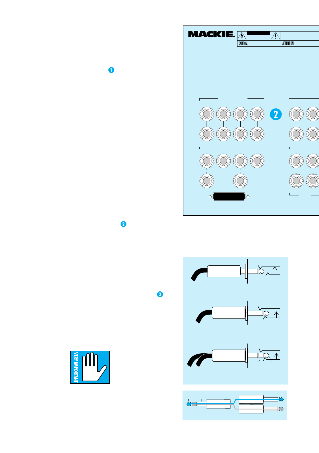
INSERTS—CHANNELS 1–4 ONLY
Stereo input modules 1 through 4 have channel
insert jacks on the back panel. An insert jack allows
you to tap the signal out of the circuit for processing
in another piece of equipment and then return the
processed audio back into the LM-3204.
The channel inserts occur just before the
balance, gain and EQ circuits and controls.
Mackie inserts use 1⁄4" TRS
phone jacks, and can be used
in three different ways:
2. As a “direct output,” which also interrupts the
1
signal to the output section. Use a
⁄4" TS
(mono) plug, and push it in all the way to the
second click.
MONO PLUG
Direct out with no signal interruption to master.
Direct out with signal interruption to master.
(TIP = send to effect, RING = return from effects)
Insert only to first click
MONO PLUG
Insert all the way in to the "second click"
STEREO
PLUG
RING
For use as an effects loop.
TIP
1. As a “direct output,” with no interruption of
the signal to the output section. Use a
1
⁄4"
TS (mono) plug, but insert it only to the
first click.
12
ring
tip
shield
this plug connects to the CR-1604
SEND
RETURN
tip
"ring"
Page 13

SERIAL NUMBER MANUFACTURING DATE
OT
R.
RSONNEL.
E TYPE.
USIBLE
MONO PLUG
INSERT ONLY INTO THE
"FIRST CLICK"
DIRECT OUT WITH
NO SIGNAL
INTERRUPTION
TO MASTER
MONO PLUG
INSERT ALL THE WAY IN TO
THE "SECOND CLICK"
CHANNEL INSERT OPTIONS
DIRECT OUT WITH
SIGNAL
INTERRUPTION
TO MASTER
STEREO
PLUG
TIP OUT TO EFFECTS DEVICE
RING RETURN FROM EFFECTS
FOR USE AS AN
EFFECTS LOOP
(TIP = SEND,
RING = RETURN)
OFF
120VAC
POWER
ON
50/60 HZ 60W
1A/250V SLO BLO
LA YOUT
AND
FUNCTION
FUSE INSIDE
CAUTION:
TO REDUCE THE
RISK OF FIRE, REPLACE WITH THE
SAME TYPE FUSE AND RATING
13 11 9 7
14 12 10 8 6 4
MAIN/TAPE OUTPUTS
RL
L
R
RL
MAIN INSERTS
3. As a send-return insert for processing. Use a
1
⁄4" TRS (stereo) plug “Y”-ed to two mono
1
(TS)
send to the effect’s input, and the ring should
be wired as the return from the effect back
into the LM-3204. The sleeve is the com mo n
ground connection.
See the Insert Jack diagram at left. The same
diagram is on the back panel of the LM-3204 for
your wiring convenience. Bring your own flashlight.
STEREO BALANCED OR UNBALANCED LINE INPUTS
TAPE INPUTS
L
R
MIC PREAMP
OUTPUT
RL
21
G
10dB50
I
N
A
dB
⁄4" plugs. The tip should be wired to
MIC PREAMP GAIN
PHANTOM
POWER
+48V
MIC IN
5
21
I
N
A
G
10dB50
dB
There is no change in signal level when using
an unbalanced (TS) cord instead of a balanced
(TRS) cord.
The Main Outputs also appear as unbalanced
outputs on the T ape L–R Out RCA jacks immediately to the right. (Also able to drive –10 to +4.)
MAIN INSERTS
The main left and right output circuits also
have insert jacks available on the back panel.
Like the channel inserts, these jacks allow you to
MAIN/TAPE OUTPUTS
The Left and Right Main Outputs are each
electronically balanced, line level outputs, capable of driving line levels of –10dBV or +4dBu
equally well.
tap the signal out of the circuit for processing in
another piece of equipment and then return the
processed audio back into the LM-3204. In this
case, the entire main left-right mixing buses will
be processed.
Each output jack is wired as a TRS (Tip-
1
Ring-Sleeve)
⁄4" phone jack. Like the balanced
input jacks, the tip of the jack is wired to the
“high” side of the input circuitry, the ring is
wired to the “low” side, and the sleeve is the
circuit ground connection.
1
Standard TS (Tip-Sleeve)
⁄4" phone plugs
may be connected to the LM-3204 Main Outputs
for connection to unbalanced equipment. The
sleeve of the TS plug will automatically connect
the low side of the jack to ground and unbalance
the output.
place to patch in a stereo compressor/limiter, EQ
and/or aural exciter . If you’r e using the LM-3204
for live sound, you may want to patch in a stereo
graphic equalizer or anti-feedback processor here.
The main inserts are the same as the channel
inserts in regard to send/return, dir ect, and direct
with interrupt wiring. See the three ways to use
31
2
(MONO)
L
R
CHANNEL INSERTS
24
3
1
L
R
The main inserts occur just
after the bus summing amplifiers and before the master Left
and Right faders. When “printing” a mix, this would be the
13
Page 14

N
16 14 12 10
15 13 11 9
(MONO)
L
R
CONTROL ROOM
OUTPUTS
ALT 3/4
OUTPUTS
RL
RL
MAIN/TAPE OUTPUTS
RL
RL
MAIN INSERTS
L
R
an insert at left, or check the patching illustration on the back of the LM-3204.
TAPE OUT AND TAPE IN
The LM-3204 provides a number of ways to
feed a tape deck, a cassette or DAT r ecorder and
to monitor the output of the recorder as well.
The Main Output connections are mentioned
earlier , and may be used as the primary feed to
your recorder.
1
⁄4" TS Tape In jacks provide a monitor
The
return from the output of your deck. The Tape In
jacks are routed through the T ape Monitor
switch in the Main Output section on the front
panel, which can send the signal to the control
room and phones.
Additionally, the LM-3204 has four unbalanced “RCA”-type connectors labeled “T ape” on
the rear panel for easy connection to your recorder . The Tape Out RCA jacks are connected
in parallel to the Main Output jacks.
The Tape In RCA jacks are connected in par-
1
allel with the Tape In
⁄4" phone jacks.
NOTE: Using the
Tape In jacks will deactivate the RCA Tape In
jacks.
AUX SENDS
Remember that on the front panel, AUX
Sends 1 and 3 were stereo sends and AUX Sends
2 and 4 were mono? Well, it’s true back here too,
where they finally come out of the mixer.
STEREO BALANCED OR U
TAPE INPUTS
L
R
MIC PREAMP
OUTPUT
1
⁄4"
AUX Sends 1 and 3 each have a left-right pair
1
of line level, unbalanced
⁄4" TS phone jacks for
connection to the outside world.
If you want to use AUX Send 1 and/or AUX
Send 3 as a good old mono AUX send (like 2 and
4), just plug your cord into the Left (MONO)
AUX Send output. Then both the Left and Right
signals will be summed into that output.
Sends 2 and 4 have one mono, unbalanced
1
RL
⁄4" TS phone jack each.
STEREO AUX RETURNS
The LM-3204 has four sets of stereo AUX returns
for bringing that fine stereo reverb and delay
back into your mix. (Even though sends 2 and 4
21
are mono, all the AUX returns are r eady for stereo signals generated within your effects boxes.)
Each input is a line level, unbalanced
standard phone jack, which routes the signal
directly to the AUX Return amplifiers and front
panel controls, and on to the main L/R mix bus. See
page 10, “Stereo Aux Returns,” for switching options.
Just like the channel inputs, using the
(Mono) Left input jack only will apply the return signal equally to both the left and right
AUX inputs for a mono return.
STEREO AUX RETURNS
1234
(MONO)
L
R
AUX SENDS
1234
STEREO
L
R
USE ONLY WITH LM-3204E EXPANDERS.
STEREO
EXPANDER IN
ALT 3/4 OUTPUTS
The Alt 3/4 Outputs are straightforward: Left
and Right line level unbalanced
each connected to the Alt 3/4 buses. Use them
for whatever you can dream up. For instance,
you could use them to send selected channels to
your multitrack deck for bouncing or overdubbing (see the hook-up diagrams farther on for
more possibilities).
L
R
1
⁄4" TS jacks,
MONO
1
⁄4" TS
14
Page 15

CONTROL ROOM OUTPUTS
This is where you plug in your monitor
power amplifier. The Left and Right Control
Room Outputs are line level unbalanced
TS jacks, controlled by the Control Room
fader on the front panel.
CONTROL ROOM
OUTPUTS
RL
MAIN/TAPE OUTPUTS
RL
L
EXPANDER IN
The Expander In jack is where you plug in your
optional LM-3204E expander. See Appendix B.
1
⁄4"
STEREO AUX RETURNS
1234
(MONO)
L
LA YOUT
AND
FUNCTION
R
ALT 3/4
OUTPUTS
RL
RL
MAIN INSERTS
MICROPHONE CONNECTIONS
Here’s a Mackie bonus: two mic preamps hidden away on the back panel!
The Mic In connectors are standard female XLR3-type microphone connectors, wired
to a pair of classic Mackie balanced mic preamplifiers with more headroom than a Kenworth
cab and less noise than a mortuary at midnight.
Pin 2 is wired high, pin 3 is low and pin 1 is
grounded, per AES standards.
Phantom mic powering can be applied to
both inputs with a flick of the Phantom Power
switch
justed by two Trim controls.
Y ou can patch the mic out signal into any channel input or even into other pieces of line level
equipment in your rack.
. Mic preamp levels are individually ad-
The mic signals won’t go
anywhere unless you patch
them. Each
G
10dB50
I
N
A
MIC PREAMP GAIN
PHANTOM
POWER
+48V
dB
G
10dB50
21
I
N
A
dB
preamp has a
line level unbal-
MIC IN
anced
Mic Out jack.
1
⁄4" TS
R
AUX SENDS
1234
MONO
STEREO
L
R
EXPANDER IN
USE ONLY WITH LM-3204E EXPANDERS.
STEREO
L
R
PHONES OUT
The Phones jack is located on the front panel
to the right of the meters and below the Phones
1
Level knob. The jack is a standard
headphone jack with the left channel on the tip,
the right channel on the ring, and the common
ground connection on the sleeve. Careful; it’s
loud. It is an IC, and it will not drive a speaker
and it will toast a power amp (if turned up).
W ARNING: Turn down the
Phones level control before
you plug in the headphones.
Then inch the control up
until you feel groovy.
CLIP
22
+
10
7
4
2
0
2
4
7
10
20
30
–
40
⁄4" TRS stereo
U
OO
+20
SOLO
OO
LEVEL
PHONES
TAPE
MONITOR
15
Page 16

SECTION 3: GENERAL INFORMA TION
Maybe you don’t need to read this at all.
Battle-scarred pros: skip to Section 4.
Beginners: face the blackboard, please.
Many of you reading this
manual have a lot of experience in using mixers and
mixing consoles. For you
battle-scarred pros, Section 2
and the Block Diagram will probably be all that
you need to look at.
For those of you who are either new to using
mixers or just like to read even larger quantities
of our glib prose, we’ve provided this short section. It discusses the basic concepts and
procedures used in recording, mixing and sound
reinforcement work. If you can make some
sense of it, you can check out your application
and patching in Section 4 and start plugging
things in.
GENERAL INFORMATION
Here is a primer covering a few important
ideas you should be on good terms with before
you sit down to a mixer .
LEVELS
Microphones have low output levels. Line
level devices have high output levels. One of the
functions of a mixer is to amplify or attenuate
these signal levels properly. Since it’s easy to degrade the signal by not handling levels well, and
since it’s your hand on the knobs, you should be
sure you know how much gain to apply and
where to apply it.
Note: No matter what
combination of cable
adapters you may have at
hand, never connect the
output of a power ampli-
fier to the input of a mixer.
Noise
Every electronic circuit produces noise or
hiss or hash or buzz, and any noise present on
the input of an electronic circuit will be faithfully passed through. Turn it up high enough,
and you will hear the noise.
Headroom
Every electronic circuit also has a point of
overload, a clip point, where the voltage simply
cannot rise any higher, no matter what the input
signal and your fader move would like. This
overload, or clipping, will show up as tooth-
16
grinding distortion.
Somewhere between the noise and the
clipping is an optimum level for your signal:
high enough above the noise floor to render
the hiss inaudible, and far enough below the
distortion point to allow range for loud peaks
of music to pass without clipping. This safe
operating zone might be called operating level
or nominal level or zero or perhaps line level.
The range between your operating level and
clipping is called headroom, which defines
just how tall your signal can be without having to duck for the rafters.
Your mission as a designated Master of the
Levels is to get the low level signals up to line
level as soon as possible and to keep them
there as much as possible, but not to turn them
up too much.
Unity Gain
On a Mackie mixer, the easy way to do this
is to set all the level controls in your path to
the “U” marks screened onto the panels. Set
the Balance control to the center and press
the channel Solo button. This will display the
channel level on the Left and Right meters.
Then adjust the channel Gain or the Mic trim
until you have a good level on the meters. The
“U” stands for unity gain, which basically
means level in = level out. Now, with mic inputs that’s not exactly the case, but ignore
that and set your faders at “U”. That will get
you in the safe zone.
Metering
Pay close attention to the meters. A meter
is an aid, a window looking onto part of the
dynamic range of your signal, and it will tell
you if your level is in the ballpark, so to speak.
Try to keep your signals in the middle
range of the meters, for the most part. If the
signal is always very low, you may not be getting the best signal-to-noise ratio you can.
If the meter LEDs are always solidly lit from
bottom to top, you are likely distorting both
the console and your recording tape regularly.
Keep the signal in the middle, with occasional
peaks into the yellow. Remember, the top
yellow LED of the meter represents a level of
+10dBu, and the LM-3204 doesn’t clip until
+22dBu. Even when “banging” the yellow
LEDs hard, you still have around 12dB of
headroom for your peaks. The Left and Right
meters have a red LED segment to show
imminent clipping at +20dBu.
Page 17

But if your music is sounding good, don’t
worry if you’re in the yellow a lot or if some
parts of the track hardly read at all. You’ll
quickly get a feel for what works for you, when
you can get away with really smacking the tape
or the electronics.
BUSES
More often than not, the goal in a mixing console is to mix two or more inputs into one
output. Like a coach who has two or more players to get to the same ballgame, console
designers use a bus. Even W ebster’s Unabridged
Dictionary agrees, defining the word bus in electronics as “a conductor serving as a common
connector for three or more circuits.”
The Mackie LM-3204 has 12 buses. The four
suggested in the name (the main Left and Right
buses and the Alt 3–4 buses) are important, but
there are also Auxiliary buses (two ster eo and
two mono = six) and a pair of solo buses. We will
try to be clear just what bus we are talking about
when we do talk about buses.
SENDS AND RETURNS
Sends are buses fed to outputs, and returns
are inputs. So why don’t we call them outputs
and inputs?
Well, actually, the terms send and return
can mean many things, but the way they are
generally used in mixing console parlance is
to refer to send buses, which tap off a little of
a signal to send to some effects device (like a
reverberation unit), and return inputs, which
function to return that reverb back into the
mix. The original, unprocessed signal is called
the “dry” signal. The reverb unit’s output signal is called the “wet” signal.
Sends are also used to tap some of the signal
from a collection of channels for a headphone
cue mix or monitor mix. For that matter, sends
can be used as additional mix buses, if needed.
In the same way, if you don’t need r eturns for
reverb or effects, they can be used as additional
line level inputs to your mix.
SOLO
Solo is a standard console function that allows you to listen to one or more sources all by
themselves (soloed).
You can check EQ, possible distortion or buzz,
or just listen to see if a particular mic is open or
not. When soloing more than one source, you
can listen to the blend of just part of your mix:
only a flute sample on channel one, for example,
or just the percussion module on channel eight.
The solo circuits are designed not to interrupt
the recording process. The solo bus signal is sent
directly to the Control Room and Headphone
outputs without affecting any of the other inputs,
outputs or recording buses. Solo circuits on the
LM-3204 are “After Fader Listen” (AFL), meaning the soloed channel’s gain control affects the
solo level.
EQ
Everybody knows what EQ is, but just in case
you’d like a refresher, we’ll put in a few paragraphs here.
Equalization (EQ) refers to purposely
changing the frequency response of a circuit,
sometimes to correct for previous unequal r esponse (hence the term, equalization), and
more often to add or subtract level at certain
frequencies for a pleasing effect.
Bass and treble controls on your stereo ar e
EQ; so are the units called parametrics and
graphics and notch filters.
A lot of how we refer to equalization has to do
with what a graph of the frequency response
would look like. A flat response (no EQ) is a
straight line; a peak looks like a hill, a dip is a valley, a notch is a r eally skinny valley, and a shelf
looks like a plateau (or a shelf). The slope is the
grade of the hill on the graph.
Graphic equalizers have enough frequency
slider controls to form a visual representation
of the EQ curve right on the front panel.
Parametric EQs let you vary several EQ parameters at once. A filter is simply a form of
equalizer which allows certain frequencies
through unmolested and other frequencies
are attenuated or removed.
The equalizer on the LM-3204 combines
two different types of EQ into three different
sections.
The LO and HI sections of the EQ are shelving
equalizers. As you can
see, shelving EQs lift or
lower the entire range
of frequencies above or
below a certain point.
The LO EQ on the
LM-3204 is at 80 Hz and
the HI is at 12 kHz, and
can vary the bass and
treble by 15dB. W e
picked these frequencies because they make
for a more musical and
pleasant sounding
equalizer; they give you
Hi shelf
Lo shelf
GENERAL
INFO
17
Page 18

more punch and more
sizzle without making
Midrange peak
the mix muddy or harsh.
The MID EQ section
is a peaking/dipping
equalizer with a bellshaped res ponse curve.
The frequency is centered
at 2.5kHz and the bandwidth is fixed. The MID EQ
can cut or boost 12dB.
CONNECTORS
If you’ve used a Mackie MicroSeries 1202, a
CR-1604 or a Mackie 8-Bus Series, you’re familiar with the various kinds of connectors used
with or mixers. If you’re new to the whole thing,
review the drawings below. They’re also described in detail in Appendix A on page 30 of
this manual.
Tip/Sleeve (TS) Plug
SLEEVE
TIP
Tip/Ring/Sleeve (TRS) Plug
SLEEVERING
TIP
Effects Send/Return connector
TIP (RETURN)
TIP (SEND)
RING
TIPSLEEVE
TIP
SLEEVE
TIPSLEEVE
RING
TIP
SLEEVE
PROCESSOR
OUTPUT
TO
PROCESSOR
INPUT
FROM
Balanced XLR Connectors
COMMON
COLD HOT
COMMON
COLD HOT
2
3
1
RCA Plug used on some outboard gear
TIPSLEEVETIPSLEEVE
RING (IN)
RING
TIP (OUT)
(RETURN)
CHANNEL INSERT
HOT
COLD
COMMON
TIP
(SEND)
TO MIXER
18
Page 19

SECTION 4: USING THE LM-3204
If you’re a seasoned patch-cord weaver and
general propellor-head, just refer the to the
way-cool hook-up drawings that start on page
22 of this section.
If, you’re a glutton for verbal effluvia, read on.
IMPORTANT SENSITIVITY ADJUSTMENT
PROCEDURE!
To fully achieve the
LM-3204 Mixer’s impressive
headroom and specs, you
must “tune” the input sensitivity for each channel. This
simple operation is so important that we’re repeating it here as well as at the beginning of this
manual. If our Technical Support department
had its way, the adjustment procedur e would
probably be repeated on every other page of this
manual. They spend a fair amount of their time
“solving” new Mackie Mixer users’ noise and
headroom “problems” by directing neophyte
owners to the IMPORT ANT SENSITIVITY
ADJUSTMENT PROCEDURE.
FOLLOW THIS PROCEDURE FOR EACH LM-
3204 CHANNEL IN USE:
1. Set the Control Room, Phones, Left and Right
Master Faders, and Solo controls all the way
off. (As you are working through the steps,
you can ease these controls up a bit to hear
what you are doing, but be careful. Ther e’s a
lotta level in this mixer .)
2. Apply signal to channel input.
Insert a stereo line input into the corre-
sponding Left and Right Input jacks at the
rear of the mixer.
or
Insert a mono line input into the corresponding Left Input jack on the rear of the mixer.
3. Set channel strip controls as follows:
Gain control at “U” detent.
Solo switch down.
Mute switch up.
Balance control at “U” detent.
EQ controls at “U” detent.
Aux controls fully counterclockwise (off).
4. Apply audio signal to the input. The material
and level you use to set up the mixer should
be vaguely representative of what you will
really be doing when you really do it. If you’r e
connected to a tape deck or a CD player , put
some music on and push the button! If you’re
hooked up to a synthesizer , tickle those
plastic ivories! On the other hand, you might
have to deviate from this approach on certain
channels. For example, you don’t want to set
the hi-hat cymbal channel at 0dB. Use your
judgement on this.
5. The channel’s –20dB LED should light. The
L/R main meters will show the actual internal
operating level of soloed signals. Now you will
optimize levels.
For a meter reading of 0 dBu with +4d Bu
input (line level) signals, the settings in step 3
should be just about right. Adjust the channel
Gain control slightly so that you get peaks that
regularly hit 0dB on the Left and Right meters.
For –10dBV signals, you may have to turn
the channel Gain control clockwise to
boost the signal to read 0dB on the Left
and Right meters.
The Long Arm Exercise: For Microphone
signals (using an onboard Mackie mic
preamp), leave the channel Gain setting at
the “U” detent and instead adjust the Mic
Trim pot on the r ear of the mixer until you
get peak levels of around 0dB on the Left
and Right meters. Remember , the sound
coming in the microphone should be typical
of what you will really be using. For patching
instructions, see page 11, “Microphone
Preamplifiers.”
6. If desired (optional):
Adjust the channel strip’s EQ to about what
you will be using during the session.
Repeat Step 5.
7. Return the channel strip’s Solo button to the
up position.
8. Repeat steps 1–7 on the next channel that is
being used.
9. As you un-solo the channel strips to listen to
your mix, ease up the Left and Right master
faders to set a good mix level on the meters,
with occasional peaks of 0dB.
MUSICAL INSTRUMENT SUBMIXER:
ST AGE
A rock stage setup used to only include
three guitar amps and a set of drums. Here at
the turn of the century, it still means guitars
and drums, but add to that samplers and
synthesizers and drum pads and guitar
synths and MIDI saxophones and delays and
reverbs and choruses and maybe even subharmonic synthesis. Imagine the joy your
USING THE
LM-3204
19
Page 20

sound engineer feels when you come at her
with your 12 output cables.
W e figur e that if you bought an LM-3204 for
stage use, you already have an equipment rack
just about full of fine electronic musical technology. So, we designed the LM-3204 to be 19" wide
and a mere 5 rack units high. To fit in your rack.
The LM-3204 will let you submix all your instruments in stereo, add your effects and provide
stage amp, sound reinforcement, monitor or recording feeds. Not only does it make the
impossible possible and clean up that nest of
cables, but it leaves the balance, EQ and effects
blend in your hands, right there in your rack.
All of your electronic instruments (and CD
players and DAT players) can patch directly
into the LM-3204 stereo inputs. Guitar and
bass preamps, whether rack-mount units or
built into the amp heads, can patch in here
too. If you have a mono instrument, simply
plug its output into the Left (MONO) jack of
the LM-3204 channel input you select.
Use the LM-3204 main Left and Right outputs to connect to the main house PA mixer, or
feed them directly into your stage amp. In fact,
you can connect to both at once, using the
main 1/4" outputs for the house mixer and the
RCA Tape outputs (which carry the same signal) for your amplifier.
You can use the Control Room outputs to
feed a small amp next to you, if you’d like. This
output will also allow you to Solo various
LM-3204 inputs to check MIDI patches, verify
presets, send a click track (via AUX Return 4’s
“AUX Return to Control Room Only” switch) to
yourself only, and so on, without affecting the
main outputs. Y ou can also use headphones on
the Phones output.
Effects such as reverb, delay or chorus
can easily be patched into the AUX send and
return circuits in the LM-3204. Gates and
compressors will usually be connected to
either a stereo pair of channel strip Insert
jacks (channel 1–4 inserts for mics, drum
machines, guitars…) or to the main Left and
Right Insert jacks. After you’ve adjusted the
compressor or gate settings as you want, adjust the effect’s overall gain for unity, so that
the level of your signal is about the same
with the insert device in or out of the circuit.
MUSICAL INSTRUMENT SUBMIXER:
STUDIO
MIDI suites and project studios run into the
same problems as large stage setups: racks full
of synthesizers and samplers eating up all the
mixing console inputs.
20
So, use your LM-3204 as a musical instrument
submixer . Connect your banks of instruments
into the stereo inputs of the LM-3204, and
patch the main Left and Right outputs into a
pair of inputs on your main console. Suddenly,
more mixing inputs appear!
EFFECTS SUBMIXER
And as long as we’re discovering more inputs for
your studio, consider your main console auxiliary
returns: do you have enough? An LM-3204 can
give you an additional 16 stereo returns with the
added bonus of EQ on the returns.
Keep the routing of the sends from your main
console the same; but run all your many effects’
stereo returns through the LM-3204, and patch
the LM-3204 Left and Right outputs back into
one pair of auxiliary returns (or into a pair of
channel inputs).
MAIN STUDIO MIXER
There’s no reason why you can’t use the
LM-3204 as your main mixer . Not everybody’s in
love with adjusting mixes with rotary controls,
but it’s not hard to get used to (a gazillion
MS1202 mixers owners can’t be all wrong). And
remember, the LM-3204 has the same legendary
sound quality that’s allowed our CR-1604 to be
used for tracking and mixing of all sorts of hits.
Plus, we’ll send you a free T -shirt if you send us a
CD or cassette mixed on the LM-3204 (see page
39 for details).
CLUB SOUND REINFORCEMENT MIXER
For a small act with entirely electronic instruments and only two vocalists, the LM-3204 is an
extremely affordable, compact and easy-to-operate sound reinforcement mixer.
Plug your mics into the two preamps in the
rear and patch the preamp outputs into a pair of
channel strips, using the Left (MONO) jacks.
Now connect your drum machines, keyboards
and samplers to more inputs. Connect your effects to the AUX sends and returns, and patch
the main Left and Right (or Control Room) outputs to your power amplifier . Turn on the
spotlights, smoke generator and bubble machine, and you’re ready.
You can use the same setup to record a
demo of your band. Simply connect a stereo
recorder to the Tape In and Tape Out jacks.
To check out what you’re recording, plug in
some headphones (or use the Control Room
outputs) and press the Tape Monitor switch.
You can record and check playback as you are
performing, if you want, without affecting
what your audience is hearing (unless a bit of
button-pushing gets you off tempo).
Page 21

DJ MIXER
Connect a couple of CD players, a DAT player
or two and a microphone. Add subwoofers and
an attitude and stir well.
The LM-3204 makes a great Disc Jockey
mixer. With stereo gain, mutes and EQ, it’s
easy to keep all your music sources balanced.
Each pair of inputs simply plugs into the back,
with the main Left and Right outputs feeding
your amplifiers.
Any processing or effects can be handled
either by using the Insert jacks or the AUX
sends and returns. You can cue and pre-audition the next selection by using headphones
and the LM-3204 Solo circuits along with
headphones plugged into the Phones jack.
Be sure the channel you want to cue is muted
(Mute 3/4 switch pushed) and then press the
Solo button.
Note: If you are using turntables and vinyl
discs, you must have a stereo phono preamplifier for each turntable for correct impedance
matching, gain and EQ response tailoring.
Connect the outputs of the phono preamplifiers into the LM-3204 line input jacks. The
Mackie LM-3204 does not have internal phono
preamplifiers. Sorry.
MUL TI-IMAGE/MULTIMEDIA MIXER
With its 16 stereo inputs, the LM-3204 is per fect for combining the multiple VCR/CD player/
DAT machine/cassette player/r eel-to-r eel/laserdisc/computer audio/you-name-it sources found in
a corporate boardroom, a focus-group cubicle or a
sales convention exhibit.
All these line level sources will plug directly
into the LM-3204, and the main Left and Right
outputs connect to the system power amplifiers.
Headphones and the Solo switches will allow you
to audition upcoming audio cues privately (be
sure the channels are muted for cueing). And, of
course, there are two microphone pr eamplifiers
for live presentations or voice-overs.
USING THE
LM-3204
21
Page 22

Stereo
Digital Delay
Sound Module
Sound Module
Cassette Deck
L in
L out
Stereo
Reverb
R in
R out
Digital Delay
Out
In
STEREO AUX RETURNS
1234
(MONO)
L
R
1234
STEREO
AUX SENDS
L
R
EXPANDER IN
USE ONLY WITH LM-3204E EXPANDERS.
STEREO
Out
In
CD Player
16 14 12
(MONO)
L
R
CONTROL ROOM
MONO
L
R
15 13 11
OUTPUTS
ALT 3/4
OUTPUTS
RL
RL
MAIN/TAPE OUTPUTS
RL
RL
MAIN INSERTS
L
R
L
R
22
P ower Am plifier
Studio Monitors
Out
Limiter
DA T or 2-track Deck
In
In
Out
Page 23

Sound Module
Sound Module
Keyboard, or other line level input
Keyboard, or other line level input
Sound Module
Sound Module
STEREO BALANCED OR UNBALANCED LINE INPUTS
10864
TAPE INPUTS
97
RL
A
G
10dB50
I
N
MIC PREAMP GAIN
PHANTOM
POWER
+48V
dB
21
G
10dB50
I
N
A
5
dB
31
CHANNEL INSERTS
3
2
(MONO)
L
R
24
1
L
Percussion Module 1
Drum
Machine 1
Drum
Machine 2
L in
Percussion Module 2
R in
MIC PREAMP
OUTPUT
R
21
MIC IN
L in
L out
Stereo
Compressor
R in
R out
L out
Stereo
Compressor
R out
LIVE 2trk RECORDING
23
Page 24

Digital Delay
CD Player
L in
L out
Stereo
Reverb
R in
R out
In
STEREO AUX RETURNS
1234
(MONO)
L
R
1234
STEREO
AUX SENDS
L
R
EXPANDER IN
USE ONLY WITH LM-3204E EXPANDERS.
STEREO
Out
16 14 12
(MONO)
L
R
CONTROL ROOM
MONO
L
R
15 13 11
OUTPUTS
ALT 3/4
OUTPUTS
RL
RL
MAIN/TAPE OUTPUTS
RL
RL
MAIN INSERTS
L
R
L
R
24
Cassette Deck
(F or checking playback
on the ’ol headphones.)
Out
In
Stereo Compressor
P ower
Amplifier
PA CabinetPA Cabinet
Page 25

Guitar Pre-amp
Sound Module
Sound Module
Keyboard, or other line level input
Sound Module
Keyboard, or other line level input
Drum
Machine
STEREO BALANCED OR UNBALANCED LINE INPUTS
10864
TAPE INPUTS
97
RL
A
G
10dB50
I
N
MIC PREAMP GAIN
PHANTOM
POWER
+48V
dB
21
G
10dB50
I
N
A
5
31
CHANNEL INSERTS
3
dB
Bass Guitar
Pre-amp
2
(MONO)
L
R
24
1
L
Compressor
MIC PREAMP
OUTPUT
R
21
MIC IN
NIGHTCLUB ACT w/2trk RECORDING
25
Page 26

Digital Delay
OutIn
STEREO AUX RETURNS
1234
(MONO)
L
Stereo
Digital Delay
Out
Cassette Deck
In
16 14 12
(MONO)
L
CD Player
15 13 11
L in
L out
Stereo
Reverb
R in
R out
R
1234
STEREO
AUX SENDS
L
R
EXPANDER IN
USE ONLY WITH LM-3204E EXPANDERS.
STEREO
R
CONTROL ROOM
OUTPUTS
RL
MONO
L
R
RL
ALT 3/4
OUTPUTS
Out
MAIN/TAPE OUTPUTS
RL
RL
MAIN INSERTS
L
R
L
R
In
Limiter
Stereo Submix Feed
to Main Mixing Console
26
Page 27

Sound Module
Sound Module
Keyboard, or other line level input
Keyboard, or other line level input
Sound Module
Sound Module
STEREO BALANCED OR UNBALANCED LINE INPUTS
10864
TAPE INPUTS
97
RL
G
10dB50
I
N
A
dB
MIC PREAMP GAIN
PHANTOM
POWER
+48V
G
10dB50
21
I
N
A
dB
5
31
CHANNEL INSERTS
3
2
(MONO)
L
R
24
1
L
Percussion Module 1
Drum
Machine 1
Drum
Machine 2
L in
Percussion Module 2
R in
MIC PREAMP
OUTPUT
R
21
MIC IN
L in
L out
Stereo
Compressor
R in
R out
L out
Stereo
Compressor
R out
STEREO SUBMIXER
27
Page 28

Reverb 2
Digital 8-track
In
Out
L in
L out
Stereo
Reverb
R in
R out
Stereo
Digital Delay
In
STEREO AUX RETURNS
1234
(MONO)
L
R
1234
STEREO
AUX SENDS
L
R
EXPANDER IN
USE ONLY WITH LM-3204E EXPANDERS.
STEREO
Out
In
Out
16 14 12
(MONO)
L
R
CONTROL ROOM
MONO
L
R
15 13 11
OUTPUTS
ALT 3/4
OUTPUTS
RL
RL
MAIN/TAPE OUTPUTS
MAIN INSERTS
RL
RL
L
R
L
R
28
P ower Am plifier
Studio Monitors
Out
Stereo Compressor
DA T or 2-track Deck
In
In
Out
Page 29

NOTE: Tascam DA-88 owners:
go buy a bunch of “y” cords!
Sound Module
Sound Module
Sound Module
Keyboard, or other line level input
Keyboard, or other line level input
Drum
Machine 1
STEREO BALANCED OR UNBALANCED LINE INPUTS
10864
TAPE INPUTS
97
MIC PREAMP
OUTPUT
RL
21
G
10dB50
I
N
A
MIC PREAMP GAIN
PHANTOM
POWER
+48V
dB
MIC IN
G
10dB50
5
21
I
N
A
dB
L in
L out
31
2
(MONO)
L
R
CHANNEL INSERTS
3
24
1
L
R
R in
R out
Stereo
Compressor
Out
Compressor
In
MULTITRACK RECORDING AND MIXING
29
Page 30

APPENDIX A: Connections
“XLR” CONNECTORS
Mackie mixers use 3-pin female “XLR” connectors on all microphone inputs, with pin 1
wired to the grounded (earthed) shield, pin 2
wired to the “high” (”hot” or positive polarity)
side of the audio signal and pin 3 wired to the
“low” (“cold” or negative polarity) side of the
signal (Figure A). All totally aboveboard and in
COMMON
COLD HOT
COMMON
COLD HOT
Figure A:
XLR Connectors
full accord with the hallowed standards dictated by the AES (Audio Engineering Society).
Use a male “XLR”-type connector, usually
found on the nether end of what is called a
“mic cable,” to connect to these inputs.
1
⁄4" TRS PHONE PLUGS AND JACKS
“TRS” stands for Tip-Ring-Sleeve, the
three connections available on a “stereo”
or “balanced” phone jack or plug. See Figure
B. TRS jacks and plugs are used in several
different applications:
2
3
1
HOT
COLD
COMMON
• Stereo Headphones, and rarely, stereo
microphones and stereo line connections.
When wired for stereo, a
1
plug is connected tip to left, ring to right
and sleeve to ground (earth). Mackie
mixers do not directly accept 1-plug-type
stereo microphones. They must be separated
into a left cord and a right cord which are
plugged into the two mic preamps.
Y ou can cook up your own adapter for a
stereo microphone adapter. “Y” two cables
1
out of a female
⁄4" TRS jack to two male
XLR plugs, one for the Right signal and one
for the Left.
• Balanced mono circuits. When wired as a
1
balanced connector , a
⁄4" TRS jack or plug
is connected tip to signal high (hot), ring
to signal low (cold), and sleeve to ground
(earth).
• Unbalanced Send/Return circuits. When
wired as send/return “Y” connector, a
TRS jack or plug is connected tip to signal
send (output from mixer), ring to signal
return (input back into mixer), and sleeve
to ground (earth).
1
⁄4"
⁄4" TRS jack or
1
⁄4"
Figure B: 1/4” TRS plugs
30
TIPSLEEVE
SLEEVERING
TIP
RING
RING
TIP
SLEEVE
Page 31

1
⁄4" TS PHONE PLUGS AND JACKS
“TS” stands for Tip-Sleeve, the two connections
1
available on a “mono”
⁄4" phone jack or plug (Fig-
ure C). TS jacks and plugs are used in many
SLEEVE
TIP
Figure C: TS plug
different applications, always unbalanced. The tip
is connected to the audio signal and the sleeve to
ground (earth). Some examples:
• Unbalanced microphones
• Electric guitars and electronic instruments
• Unbalanced line level connections
NOTE: All the unbal-
1
anced
⁄4" inputs on the
LM-3204 have the ring conductor wired to the shield
(ground), so that you can
plug in a balanced cord with no loss of level.
ANOTHER NOTE: All the unbalanced
outputs on the LM-3204 implement “impedance balancing”. When you plug a balanced
cord into one of these, both the tip and ring
conductors have equal impedance, significantly
improvings common mode characteristics. In
other words, although unbalanced, a balanced
input receiving this cord will “think” it’s getting
a balanced signal!
SWITCHED 1⁄4" PHONE JACKS
Switches can be incorporated into 1⁄4" phone
jacks which are activated by inserting the plug.
These switches may open an insert loop in a circuit, change the input routing of the signal or
serve other functions. The Mackie LM-3204 uses
switches in the channel insert and bus insert
jacks, input jacks, AUX sends and AUX returns labeled “(MONO) Left.” See Special Mackie
Connections farther on. W e also use these
switches to ground the line level inputs when
nothing is plugged into them.
In most cases, the plug must be inserted
fully to activate the switch. Mackie takes
advantage of this
TIPSLEEVETIPSLEEVE
in some circuits,
specifying circum-
Figure D: RCA plug
plug only partially. Once again, see Special
Mackie Connections, later in this section.
stances where you
are to insert the
TIPSLEEVE
TIP
SLEEVE
1
⁄4"
RCA PLUGS AND JACKS
RCA-type plugs (also known as phono
plugs) and jacks are often used in home stereo
and video equipment and in many other applications (Figure D). They are unbalanced, and
1
electrically identical to a
⁄4" TS phone plug or
jack. Connect the signal to the center post and
the ground (earth) or shield to the surrounding “basket.” Tape In and Tape Out are availabl e
on RCA jacks on the Mackie LM-3204.
UNBALANCING A LINE
In most studio, stage and sound reinforcement situations, there is a combination of
balanced and unbalanced inputs and outputs on
the various pieces of equipment. This usually will
not be a problem in making connections.
• When connecting a balanced output to an
unbalanced input, be sure the signal high
(hot) connections are wired to each other,
and that the balanced signal low (cold) goes
to the ground (earth) connection at the
unbalanced input. In most cases, the
balanced ground (earth) will also be
connected to the ground (earth) at the
unbalanced input. If there are hum or radio
frequency ground-loop problems, this
connection may be left disconnected at the
balanced end.
• When connecting an unbalanced output to a
balanced input, be sure that the signal high
(hot) connections are wired to each other.
The unbalanced ground (earth) connection
should be wired to the low (cold) and the
ground (earth) connections of the balanced
input. If there are ground-loop problems, try
connecting the unbalanced ground (earth)
connection only to the input low (cold)
connection, and leaving the input ground
(earth) connection disconnected.
In some cases, you will have to make up special adapters to interconnect your equipment. For
example, you may need a balanced XLR female
1
connected to an unbalanced
⁄4" TS phone plug.
SPECIAL MACKIE CONNECTIONS
The balanced-to-unbalanced connection
has been anticipated in the wiring of the
1
Mackie LM-3204 jacks. A
1
⁄4" TRS balanced input, for example,
into a
will automatically unbalance the input and
make all the right connections. Conversely, a
1
⁄4" TRS plug inserted into a 1⁄4" unbalanced input will automatically tie the ring (low or
cold) to ground (earth).
⁄4" TS plug inserted
APPENDIX
31
Page 32

TRS Send/Receive Insert Jacks
The insert jacks on both the LM-3204 input
channels 1-4 and on the left and right main
1
buses are the three-conductor, TRS type
⁄4"
phone. They are unbalanced, but have both the
mixer output (send) and the mixer input (return) signals in one connector (See Figure B).
The sleeve is the common ground (earth)
for both signals. The send from the mixer to
the external unit is carried on the tip, and the
return from the unit to the mixer is on the ring.
Using the Send Only on an Insert Jack
If you insert a TS (mono) 1/4" plug only
partially (to the first click) into an LM-3204
insert jack, the plug will not activate the jack
switch and will not open the insert loop in the
circuit (thereby allowing the channel signal to
continue on its merry way through the mixer).
This allows you to tap out the channel or
bus signal at that point in the circuit without
interrupting normal operation.
1
If you push the
click, you will open the jack switch and create
a direct out, which does interrupt the signal in
that channel. See Figure F.
MONO PLUG
Direct out with no signal interruption to master.
Insert only to first click
MONO PLUG
Direct out with signal interruption to master.
Insert all the way in to the "second click"
For use as an effects loop.
(TIP = send to effect, RING = return from effects)
⁄4" TS plug in to the second
STEREO
PLUG
RING
TIP
Note: Do not overload or
short-circuit the signal you
are tapping from the mixer .
That will affect the internal
signal in the LM-3204.
MACKIE STEREO INPUTS AND RETURNS:
Mono, Stereo, Whatever
The LM-3204 stereo line inputs, stereo AUX
sends and stereo AUX returns are a fine example
of the Mackie philosophy (which we just made
up) of Maximum Flexibility with Minimum
Headache. The inputs and returns will automatically be mono or stereo, depending upon
how you use the jacks. Here’s how it works:
A mono signal should be patched into
the input or return jack labeled Left
(MONO). The signal will be routed to both
the left and right sides of the return circuit, and will show up in the center of the
stereo pair of buses it’s assigned to, or can
be “panned” with the Balance control.
A stereo signal, having
two plugs, should be patched
into the Left (MONO) and
the RIGHT input or return
jacks. A jack switch in the
RIGHT jack will disable the mono function,
and the signals will show up in stereo.
A mono signal connected to the RIGHT jack
will show up in the right bus only. You probably
will only want to use this sophisticated effect
for special occasions (weddings, bar mitzvahs,
Rush Limbaugh’s birthday party, etc.)
MULTS AND “Y”s
A mult or “Y” connector allows you to
route one output to two or more inputs by
simply providing parallel wiring connections.
You can make “Y”s and mults for the outputs
of both unbalanced and balanced circuits.
Remember: Only mult
or “Y” an output into several inputs. If you need to
combine several outputs
into one input, you must
use a mixer, not a mult or a “Y.”
Figure E
ring
tip
shield
this plug connects to the CR-1604
Figure F
32
SEND
RETURN
tip
"ring"
Page 33

APPENDIX B: OPTIONS, ADD-ONS
AND EXTRA STUFF
LM-3204E Stereo Line Expander
Nobody ever has enough inputs. And when
16 stereo line inputs are finally too few, you, a
proud Mackie LM-3204 owner, don’t even need
to think about a new mixer. For less than the
price of another LM-3204, you can get an
LE-3204E Stereo Line Expander and add
another 16 stereo line inputs to your system.
It looks just like an LM-3204 but without
the Master Section.
But why stop there? You can expand your
expander, and expand that expander, and
expand that expander, until you reach the
theoretical limit of 65,536 inputs or the weight
limitation of your building. (Actually, there IS
some residual noise build-up — utterly
inaudible when adding two or three or four
expanders, so we suggest keeping it to that
number).
Contact your dealer.
APPENDIX
33
Page 34

APPENDIX C: SPECIFICA TIONS: TECH STUFF
LM-3204 Owner’s Manual Specs
Noise (20Hz to 20kHz bandwidth, Line inputs to Main
L/R outputs, all channels assigned):
Master fader down, Ch. gains down –104.2dBu
Master fader @ unity, Ch. gains down –86.6dBu
Master fader @ unity, Ch. gains @ unity –84.0dBu
Total Harmonic Distortion
(1KHz @ +14dBu 20Hz–20kHz, Channel input):
Main L /R output .0022%
Control Room output .0024%
Alt 3–4 output .0016%
Crosstalk (1kHz @ 0dBu, 20Hz to 20Khz bandwidth,
channel in to Main Left outputs):
Channel gain down, channels 2–16 at Unity –73dBu
Channel muted, channels 2–16 at Unity –81dBu
Frequency Response (any input to any output):
20Hz to 50KHz +0dB/–1dB
20Hz to 100KHz +0dB/–3dB
Maximum Levels
Mic preamp input +14dBu
All other inputs +22dBu
All outputs +22dBu
Impedances
Mic preamp input 5k
All other inputs 10k
All outputs 120
Equalization
Lo EQ Shelving 80Hz +/–15dB
Mid EQ Peak 2kHz +/–12dB
Hi EQ Shelving 12kHz +/–15dB
Microphone Preamp
E.I.N. (150 terminated, max gain): –129dBm
Power Requirements
120 VAC, 50/60Hz, 60 watts
Weight
LM-3204 console 24 lbs.
LM-3204 Gain Path Diagram — all levels in dBu
+14 max in
-10 trim dn
MIC INPUT
-50 trim up
+22 max in
LINE INPUT GAIN
+22 max in
0
0
0
0
INSERT
gain up +30
level up +20
0
AUX RETURNTAPE INPUT
lo/hi +15
mid +12
mid -12
lo/hi -15
EQ
CHANNEL
00
0(B)
MIX INSERT
level up +15
-6-6
CH. LEVEL
fader up +10
0
FADER OUTPUT
OUTPUT SECTION
max out +22
00
0
OUTPUT
MIX
AUX SEND
0
max out +22
0
max out +22
00
ALT OUTPUT
max out +22
fader up +10
0
CONTROL ROOM
0
METER FEED
(0dB @ O/P = 0dB @ METERS)
level up 0
to meters
0
34
Page 35

LM-3204 LINE MIXER
Dimensions also apply to LM-3204E Expander.
7/94
©1994 MACKIE DESIGNS INC.
LM-3204
WEIGHT
21 lbs.
9.66"8.73"
17.50"
19.00"
.75
APPENDIX
5 rack spaces
(5U)
9.66"
8.65"
35
Page 36

LEFT (MONO)
LINE IN
MAIN 1-2
ALT 3-4
LRL
R
•
•
INSERT
•
+
-
•
(CH’s 1-4)
•
EQ
LO MID HI
MUTE/
ALT 3-4
•
•
•
•
•
BAL/UNBAL
INPUTS
RIGHT
LINE IN
LEFT (MONO)
AUX RETURN 1
RIGHT
LEFT (MONO)
AUX RETURN 2
RIGHT
LEFT (MONO)
AUX RETURN 3
RIGHT
STEREO
CHANNEL
1 of 16
•
•
SOURCE ALT 3-4
•
BALANCE
LEVEL
•
•
INSERT
+
-
LEVEL
•
•
•
•
(CH’s 1-4)
CLIP LED
-20 LED
•
•
LO MID HI
EQ
•
•
•
SOLO
•
SHIFT
•
AUX 1/3
•
•
CONTROL
•
•
∑
∑
AUX 2/4
•
•
•
•
•
•
LEVEL
LEVEL
•
•
•
48 V
•
•
MACKIE
MIC PREAMPS
•
•
•
••
•
TRIM
+
-
TRIM
+
-
•
MIC 1
OUT
MIC 2
OUT
•
•
•• ••
LEFT (MONO)
AUX RETURN 4
RIGHT
•
36
LEVEL
RET 4 TO
CONTROL ROOM ONLY
OPTIONAL
LM-3204E
EXPANDER
To Schenectady
Page 37

AUX 1
LRL
•
•
BLOCK DIAGRAM
Rev. 3.3 - 8/15/94
AUX 3
AUX 4
AUX 2
•
•
L
R
•
•
•
LM-3204
©1994 Mackie Designs
SOLO
CONTROL
R
CLIP
10
7
4
2
0
-2
-4
-7
-10
-20
-30
-40
•
•
∑
∑
•
•
RL METER
L MAIN
INSERT
•
R MAIN
INSERT
•
L FADER
LEFT
+
•
-
R FADER
+
-
•
•
TAPE
MONITOR
•
∑
•
•
∑
•
•
C/R FADER
PHONES
LEVEL
•
•
MAIN
OUT
RIGHT
MAIN
OUT
L
CONTROL
ROOM OUT
R
PHONES
OUT
TAPE IN
LEFT
APPENDIX
•
•
•••••• •••
•
•
•
•
•
•
TAPE IN
RIGHT
•
•
∑
∑
∑
∑
•
•
SOLO
LEVEL
•
•
SOLO
RELAY
DRIVER
∑
∑
∑
∑
∑
∑
∑
∑
L
ALT 3-4
OUT
R
L ( MONO)
AUX 1
OUT
R
AUX 2
OUT
L ( MONO)
AUX 3
OUT
R
AUX 4
OUT
37
Page 38

APPENDIX D: SER VICE
PLEASE! SAVE THE SHIPPING BOX!
Yes, we know that it’s slightly larger than
the suitcase you’re living out of, but you will
need the entire carton and internal foam if
your mixer ever needs service at some time in
the future.
If your kids make the box into a gerbil palace and cut holes in it — or if you stuff it in
the dumpster of the fast-food place next door
to your studio, we may have to sell and ship
you another packing box later on.
Don’t end up buying an empty box!
SERVICE
Mackie mixing systems are notoriously bullet-proof and reliable. But, hey...stuff happens.
Any electronic product with as many parts as
a 40-input audio mixer can occasionally have
a minor casualty somewhere inside.
And even if we could build our products to
never break, there are those acts of nature
that tend to visit mixing boards on occasion:
spilled coffee, toppling monitors, lizard infestations, etc. This section covers how to get
your Mackie LM-3204 mixer healthy again.
TROUBLESHOOTING
It benefits everyone if you do a bit of basic
troubleshooting in advance of panicking and
sending the unit back. Some low-key detective work will determine whether or not
your mixer is really malfunctioning. First, it
saves you downtime and embarrassment if,
for example, you discover that the only thing
wrong is an unplugged power cord. Second,
it will save money. If you ship your mixer to
Mackie and we can’t duplicate the problem,
you may get slapped with a service charge
(plus shipping costs).
We could write a whole manual on troubleshooting, but our main point is that there are
a few obvious things you can easily look for:
Power connections. This sounds insultingly simple, but if the whole mixer is
completely dead, it’s time to make sure
that: the power cable is connected into a
live source of power, the mixer is turned
on, the fuse is OK, etc.
Intermittent signal problems. Faulty plugs
and cables are often the culprits. A TRS plug
can sit in a socket for months doing its job
and then suddenly decide (based on the
phase of the moon and barometric pressure)
to short or stop conducting. If you’re having
trouble with an individual channel, send or
return, for gosh sakes swap cables before
sending the mixer in for service.
Check patching and switch positions.
The LM-3204 is not a Boeing 777 (the Glass
Cockpit pride of the Northwest) but it is
possible to have a switch in the wrong
position and not notice it. How about the
Tape Monitor switch? Or, have you plugged
something into a channel or bus Insert jack?
Finally, it doesn’t hurt to call our
Product Support Department at
800/258.6883 (8:00 AM–5:00 PM
Pacific Time) to see if they have any
ideas as to what might be wrong.
WHERE IT GETS FIXED
Service and repairs of Mackie LM-3204
mixers are to be performed only at our hightech, rainforest factory.
Unauthorized service, repairs or modification will void your warranty.
TO OBTAIN FACTORY SERVICE:
1. Call Mackie Customer Service at
800/258-6883 (Monday through Friday 8:00
AM–5:00 PM Pacific Time) to get a Return
Authorization Number (RA number).
Products returned without an RA
number will be refused.
2. Pack the LM-3204 mixer in its original
shipping carton. If you do not have the
carton, request one when you get your RA
number , and we’ll send a shipping carton
out promptly. Ther e may be a charge,
however—we put those huge “SAVE THE
BOX” warnings in this manual for a reason.
Make sure that you encase the mixer in its
plastic wrapper and insert all the foam
blocks to properly protect the mixer .
3. When packing the mixer , include:
A. a note explaining exactly how to
duplicate the problem.
B. a copy of the sales receipt showing price
and date. If we cannot duplicate the problem
at the Mackie factory or establish the starting
date of your Limited W arranty , we may, at our
option, charge for service time.
C. your complete return str eet addr ess (no
P.O. boxes or route numbers, please!) and
DAYTIME phone number.
38
Page 39

4. Write the RA number plainly on the
outside of the shipping carton in BIG
print (those huge stinky sign markers
work well for this).
5. Ship the product in its original shipping
carton, freight prepaid to:
Mackie Designs
20205 144th Avenue N.E.
Woodinville, WA 98072
U.S.A.
A FREE T-SHIRT OFFER
We love to hear what folks have created
using our mixers. If you use your LM-3204 to
track or mix (or track and mix) a CD or cassette that is commercially released, we’ll trade
you a copy for a genuine Mackie T-shirt.
If you send us some notes as to when and
where and how the production was accomplished, a picture of your cassette or CD, a
short caption will probably end up in our
monthly newsletter.
Also Greg Mackie listens to most of ’em.
By “commercially released,” we mean
“offered for sale,” even if it’s just being sold
in your local area, during band breaks at
clubs or via mail order.
No hand-lettered dubs, please. Save those
for our infrequent Mixed on a Mackie contests.
To get your genuine 100% cotton, Made in
USA, Mackie celebrity T-shirt, send your cassette or CD to:
Bouquets and brickbats
This manual was primarily written by Dave
Matthew, with additional scribbles by Ron
Koliha. It was viciously scribbled up with red
pens by the Mackie Technical Support
Department and by Manufacturing Engineering Honcho, Jeff Gilbert. Valiant attempts at
proofreading by Linn Compton. Composed on
souped-up Mac™s in PageMaker™ 5.0 by the
galley slaves in the Mackie Digital Mosh Pit.
As is invariably the case, there are mistakes and fuzzy parts that need correction.
Feel free to write us with your comments and
criticisms. We do respond to outside input
— except for the occasional priggish letters
that take us to task for our lighthearted writing style. Since comments run 100-to-1 FOR
our non-stuffy style, we tend to ignore comments about how smart-alecky we are and
secretly hope that the writers are condemned
to a lifetime of reading other companies’ often
dry or incomprehensible manuals.
©1994, Mackie Designs, All Rights Reserved.
Printed in the USA.
APPENDIX
Mackie Designs
FREE T-SHIRT OFFER
attn: Communications Department
20205 144th Ave. NE
Woodinville, WA 98072
Make sure to specify L, XL or XXL size.
If you prefer a small or medium size, just
request a Large and run it through a hot dryer
several times.
Allow several weeks for delivery. We’re
always busier than a carrion fly at a Rottweiler
convention.
39
Page 40

This page left blank intentionally.
40
 Loading...