

MACKIE 1640 User Manual

OWNER’S MANUAL
Important Safety Instructions
1. Read these instuctions.
2. Keep these instructions.
3. Heed all warnings.
4. Follow all instructions.
5. Do not use this apparatus near water.
ONYX 1640
6. Clean only with dry cloth.
7. Do not block any ventilation openings. Install in accordance with the
manufacturer’s instructions.
8. Do not install near any heat sources such as radiators, heat registers,
stoves, or other apparatus (including amplifi ers) that produce heat.
9. Do not defeat the safety purpose of the polarized or grounding-type
plug. A polarized plug has two blades with one wider than the other.
A grounding-type plug has two blades and a third grounding prong.
The wide blade or the third prong are provided for your safety. If the
provided plug does not fi t into your outlet, consult an electrician for
replacement of the obsolete outlet.
10.
Protect the power cord from being walked on or pinched particularly at
plugs, convenience receptacles, and the point where they exit from the
apparatus.
11.
Only use attachments/accessories specifi ed by the manufacturer.
12.
Use only with a cart, stand, tripod, bracket, or table specifi ed by the
manufacturer, or sold with the apparatus. When a cart is used, use
caution when moving the cart/apparatus combination to avoid injury
from tip-over.
PORTABLE CART WARNING
Carts and stands - The
Component should be used
only with a cart or stand
that is recommended by
the manufacturer.
A Component and cart
combination should be
moved with care. Quick
stops, excessive force, and
uneven surfaces may cause
the Component and cart
combination to overturn.
CAUTION AVIS
RISK OF ELECTRIC SHOCK
DO NOT OPEN
RISQUE DE CHOC ELECTRIQUE
NE PAS OUVRIR
CAUTION: TO REDUCE THE RISK OF ELECTRIC SHOCK
DO NOT REMOVE COVER (OR BACK)
NO USER-SERVICEABLE PARTS INSIDE
REFER SERVICING TO QUALIFIED PERSONNEL
ATTENTION: POUR EVITER LES RISQUES DE CHOC
ELECTRIQUE, NE PAS ENLEVER LE COUVERCLE. AUCUN
ENTRETIEN DE PIECES INTERIEURES PAR L’USAGER. CONFIER
L’ENTRETIEN AU PERSONNEL QUALIFIE.
AVIS: POUR EVITER LES RISQUES D’INCENDIE OU
D’ELECTROCUTION, N’EXPOSEZ PAS CET ARTICLE
A LA PLUIE OU A L’HUMIDITE
The lightning flash with arrowhead symbol within an equilateral
triangle is intended to alert the user to the presence of uninsulated
"dangerous voltage" within the product’s enclosure, that may be
of sufficient magnitude to constitute a risk of electric shock to persons.
Le symbole clair avec point de fl che l’int rieur d’un triangle
quilat ral est utilis pour alerter l’utilisateur de la pr sence
l’int rieur du coffret de "voltage dangereux" non isol d’ampleur
suffisante pour constituer un risque d’ l ctrocution.
The exclamation point within an equilateral triangle is intended to
alert the user of the presence of important operating and maintenance
(servicing) instructions in the literature accompanying the appliance.
Le point d’exclamation l’int rieur d’un triangle quilat ral est
employ pour alerter les utilisateurs de la pr sence d’instructions
importantes pour le fonctionnement et l’entretien (service) dans le
livret d’instruction accompagnant l’appareil.
13.
Unplug this apparatus during lightning storms or when unused for long
periods of time.
14.
Refer all servicing to qualifi ed service personnel. Servicing is required
when the apparatus has been damaged in any way, such as powersupply cord or plug is damaged, liquid has been spilled or objects have
fallen into the apparatus, the apparatus has been exposed to rain or
moisture, does not operate normally, or has been dropped.
15.
This Onyx mixer has been designed with Class-I construction and must
be connected to a mains socket outlet with a protective earthing connection (the third grounding prong).
16.
This Onyx mixer has been equipped with an all-pole, rocker-style AC
mains power switch. This switch is located on the rear panel and
should remain readily accessible to the user.
17.
This apparatus does not exceed the Class A/Class B (whichever is
applicable)
set out in the radio interference regulations of the Canadian Department
limits for radio noise emissions from digital apparatus as
of Com mu ni ca tions.
ATTENTION — Le présent appareil numérique n’émet pas de bruits
radioélectriques dépassant las limites applicables aux appareils numériques de
class A/de class B (selon le cas) prescrites dans le réglement sur le brouillage
radioélectrique édicté par les ministere des com mu ni ca tions du Canada.
18.
Exposure to extremely high noise levels may cause permanent hearing
loss. Individuals vary considerably in susceptibility to noise-induced
hearing loss, but nearly everyone will lose some hearing if exposed to
suffi ciently intense noise for a period of time. The U.S. Government’s
Occupational Safety and Health Administration (OSHA) has specifi ed
the permissible noise level exposures shown in the following chart.
According to OSHA, any exposure in excess of these permissible limits
could result in some hearing loss. To ensure against potentially dangerous exposure to high sound pressure levels, it is recommended that all
persons exposed to equipment capable of producing high sound pressure levels use hearing protectors while the equipment is in operation.
Ear plugs or protectors in the ear canals or over the ears must be worn
when operating the equipment in order to prevent permanent hearing
loss if exposure is in excess of the limits set forth here.
Duration Per Day Sound Level dBA, Typical
In Hours Slow Response Example
8 90 Duo in small club
6 92
4 95 Subway Train
3 97
2 100 Very loud classical music
1.5 102
1 105 Tami screaming at Adrian about deadlines
0.5 110
0.25 or less 115 Loudest parts at a rock concert
WARNING — To reduce the risk of fi re or
electric shock, do not expose this apparatus
to rain or moisture.
2
ONYX 1640

Table of Contents
Introduction................................................................................................................4
Getting Started ..........................................................................................................5
Zero the Controls.......................................................................................................................................5
Connections.................................................................................................................................................5
Set the Levels ..............................................................................................................................................5
Instant Mixing.............................................................................................................................................5
Hookup Diagrams......................................................................................................6
Onyx 1640 Features.................................................................................................10
Channel Strips...........................................................................................................................................10
Control Room Matrix, Metering, and Phones.................................................................................. 13
TALKBACK Section...................................................................................................................................14
Auxiliary Section...................................................................................................................................... 17
Owner’s Manual
Rear Panel..................................................................................................................................................20
Appendix A: Service Information....................................................................... 24
Warranty Service..................................................................................................................................... 24
Troubleshooting...................................................................................................................................... 24
Repair ..........................................................................................................................................................25
Appendix B: Connections ..................................................................................... 26
Appendix C: Technical Info .................................................................................. 29
Onyx 1640 Specifi cations...................................................................................................................... 29
Onyx 1640 Block Diagram...................................................................................................................... 31
Appendix D: Rotopod Instructions.....................................................................32
Rear Mounting the Pod Section...........................................................................................................32
Rack Mounting the Onyx 1640.............................................................................................................34
Onyx 1640 Limited Warranty...............................................................................35
Don’t forget to visit our website at www.mackie.com for more
information about this and other Mackie products.
Part No. 0008669 Rev. A 5/04
©2004 LOUD Technologies Inc. All Rights Reserved.
Owner’s Manual
3
Introduction
Thank you for choosing a Mackie Onyx 1640 professional compact mixing console. The Onyx Series of mixers are designed for the digital era and offer the newest
features and latest technologies for live sound reinforcement and analog or digital studio recording in a durable,
road-worthy package.
ONYX 1640
The Onyx 1640 is equipped with sixteen of our new
premium precision-engineered studio-grade Onyx mic
preamps. Mackie is renowned for the high-quality mic
preamps used in our mixers, and the Onyx mic pre’s are
better than ever, with specifi cations rivaling expensive
stand-alone mic preamplifi ers.
Channels 1 and 2 feature high-impedance instrument/
line-level inputs so you can connect an acoustic, electric, or bass guitar directly into the mixer, eliminating
the need for an external direct box.
Each of the sixteen mono channels has individual
phantom power switches, low-cut fi lters, pre-EQ channel inserts, and an all new four-band EQ design with
sweepable mids and EQ bypass switch.
All sixteen channels have six Aux sends, Pan, Mute, Sub
Assign, Solo, 60 mm faders, and four signal level indicators.
A built-in Talkback mic with routing switches allows
you to communicate through the Aux Sends 1-4, Aux
Sends 5-6, Sub 1-4, or the Phones output.
All sixteen channels have balanced recording outputs
on two DB-25 connectors for multitrack recording. An
optional FireWire card provides all sixteen direct outputs
and the L-R Main Mix on a FireWire interface for streaming digital audio to a laptop for multitrack recording in a
live situation, or connecting to a DAW in a home studio.
Like our popular 1604-VLZ PRO, the Onyx 1640 has a
“rotopod” connector section. This allows the connector
panel to rotate so it faces up (all the connectors are on
the same surface as the knobs and faders), to the rear
(default mixer confi guration), or toward the back (for
rack mounting, using the included rack ears).
Please write your serial number here for future
reference (i.e., insurance claims, tech support,
return authorization, etc.)
Purchased at:
Date of purchase:
HOW TO USE THIS MANUAL
We know that many of you can’t wait to get your new
mixer hooked up, and you’re probably not going to read
the manual fi rst (sigh!). So the fi rst section after this
Introduction is a Quick-Start Guide to help you get the
mixer set up fast so you can start using it right away.
Right after that are the ever popular hook-up diagrams
that show typical mixer setups for live sound, recording,
and mixdown.
Then, when you have time, read the Features Description section. This describes every knob, button, and
connection point on the Onyx 1640, roughly following
the signal fl ow through the mixer from top to bottom
and left to right.
Throughout this section you’ll fi nd illustrations with
each feature numbered. If you want to know more about
a feature, simply locate it on the appropriate illustration, notice the number attached to it, and fi nd that
number in the nearby paragraphs.
This icon marks information that is
critically important or unique to the
Onyx 1640. For your own good, read
them and remember them. They will
be on the fi nal test.
This icon leads you to in-depth
explanations of features and practical tips. While not mandatory, they
usually have some valuable nugget of
information.
A PLUG FOR THE CONNECTOR SECTION
Appendix B is a section on connectors: XLR connectors, balanced connectors, unbalanced connectors, and
special hybrid connectors.
More resources on our website at www.mackie.com.
THE GLOSSARY: A Haven of Non-Techiness for
the Neophyte
The “Glossary of Terms” is a fairly comprehensive
dictionary of pro-audio terms. If terms like “clipping,”
“noise fl oor,” or “unbalanced” leave you blank, refer to
this glossary for a quick explanation.
ARCANE MYSTERIES ILLUMINATED
“Arcane Mysteries” discusses some of the down ‘n’
dirty practical realities of microphones, fi xed installations, grounding, and balanced versus unbalanced lines.
It’s a goldmine for the neophyte, and even the seasoned
pro might learn a thing or two.
4
ONYX 1640

Getting Started
READ THIS PAGE!!
Even if you’re one of those people
who never reads manuals, all we ask
is that you read this page now before
you begin using the Onyx 1640. You’ll
be glad you did!
Zero the Controls
1. Turn down the channel GAIN, AUX, and Fader controls, and center the channel EQ and PAN controls.
Owner’s Manual
a line input such as a CD player or tape recorder
output. Be sure that the volume of the input source
is the same as it would be during normal use. If it
isn’t, you might have to readjust these levels during
the middle of the set.
3. Adjust the channel’s GAIN [4] control so that the
LEDs on the RIGHT meter [31] stay around “0” and
never go higher than “+7.”
4. If you’d like to apply some EQ, do so now and return
to step 3. Remember to push in the EQ IN/OUT button or the EQ controls won’t do anything.
5. Disengage that channel’s SOLO switch.
6. Repeat for each channel.
2. Set all push button switches to their “out” positions.
3. In the output section (right hand side), turn all the
rotary knobs “down,” the switches “out,” and the
SUB 1-4 and MAIN MIX faders down.
4. Turn the POWER switch off.
Connections
If you already know how you want to connect the Onyx
1640, go ahead and connect the inputs and outputs
the way you want them. If you just want to get sound
through the mixer, follow these steps:
1. Plug in the detachable linecord, connect it to an AC
outlet, and turn on the Onyx 1640’s POWER switch.
Plug a microphone or other signal source into
2.
channel 1’s MIC or LINE input.
3. Connect cords from the Onyx 1640’s MAIN OUTS
(XLR connectors or 1/4" TRS connectors on the
rear panel) to your amplifi er.
4. Hook up speakers to the amp and turn it on. If the
amplifi er has level controls, set them however the
manufacturer recommends (usually all the way up).
Set the Levels
To set the channel GAIN controls, it’s not even neces-
sary to hear what you’re doing at the outputs of the
mixer. If you want to listen while you work, plug headphones into the PHONES jack on the front panel, then
set the PHONES knob about one-quarter of the way up.
The following steps must be performed one channel at
a time.
1. Push in the channel’s SOLO [17] switch. Make sure
the SOLO MODE [34] switch is up (PFL).
2. Play something into the selected input. This could
be an instrument, a singing or speaking voice, or
Instant Mixing
1. Leave the microphone plugged into channel 1 and
connect a keyboard, guitar or other instrument to
channel 2. Be sure to “Set the Levels” for channel 2
as described above.
2.
To get sound out of the speakers, turn up channel 1
and 2 faders to the “U” mark, push in the MAIN MIX
ASSIGN buttons on channels 1 and 2, and slowly turn
up the MAIN MIX fader to a comfortable listening level.
3. Sing and play. You’re a star! Adjust the faders for
channels 1 and 2 to bring your voice and your
instrument up and down to create your own mix.
Other Nuggets of Wisdom
• For optimum sonic performance, the channel and
MAIN MIX faders should be set near the “U” (unity
gain) markings.
• Always turn the MAIN MIX fader and CONTROL
ROOM knob down before making connections to
and from your Onyx 1640.
• When you shut down your equipment, turn off the
amplifi ers fi rst. When powering up, turn on the
amplifi ers last.
• Never listen to loud music for prolonged periods.
Please see the Safety Instructions on page 2 for
information on hearing protection.
• Save the shipping box! You may need it someday,
and you don’t want to have to pay for another one.
That’s it for the “Getting Started” section. Next comes
the “Hookup” section that shows you some typical ways
that you might use the Onyx 1640 in real applications.
After that, you can take the grand tour of the mixer,
with descriptions of every knob, button, input, and
output. We encourage you to take the time to read all of
the feature descriptions, but at least you know it’s there
if you have any questions.
Owner’s Manual
5
Hookup Diagrams
r
Bass Guitar Electric Guitar
ONYX 1640
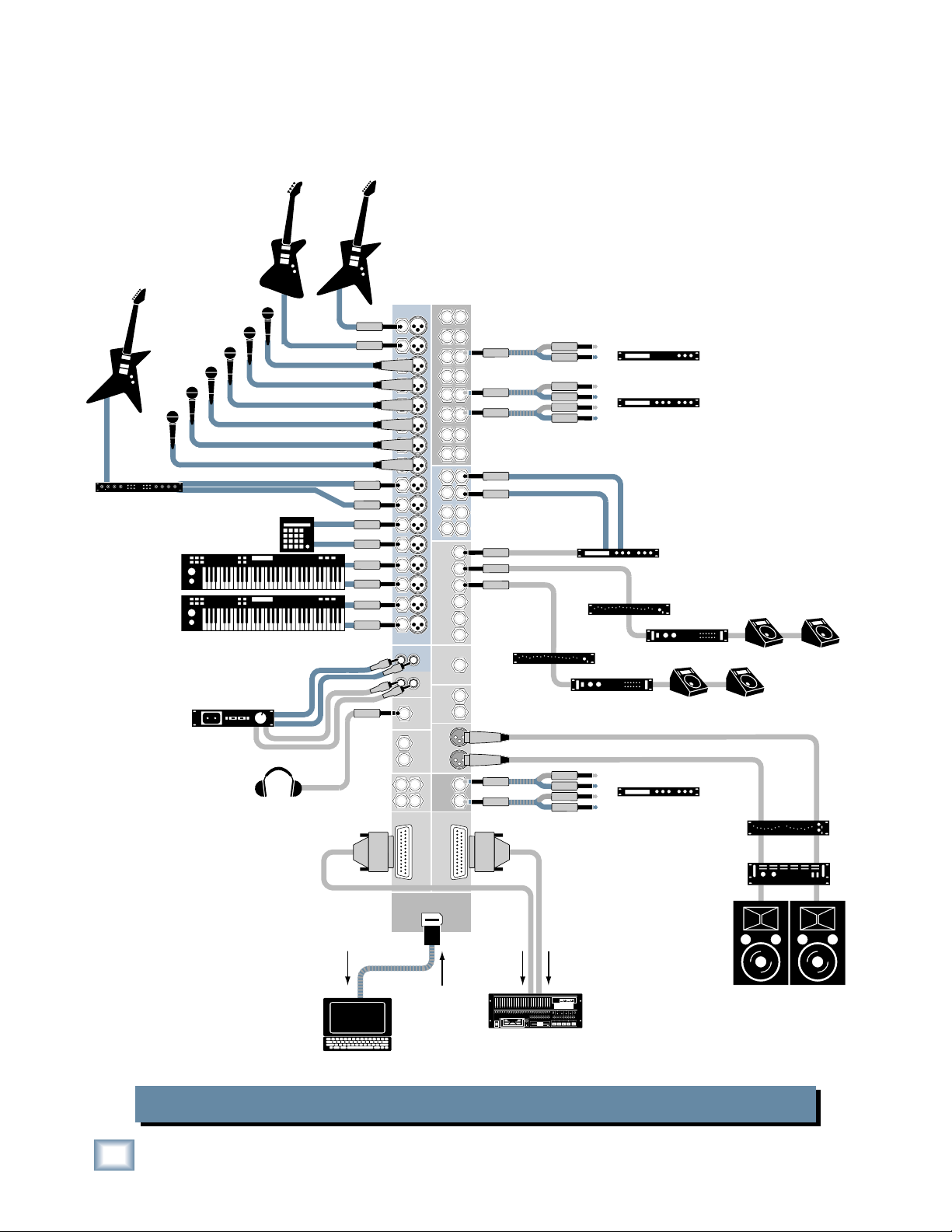
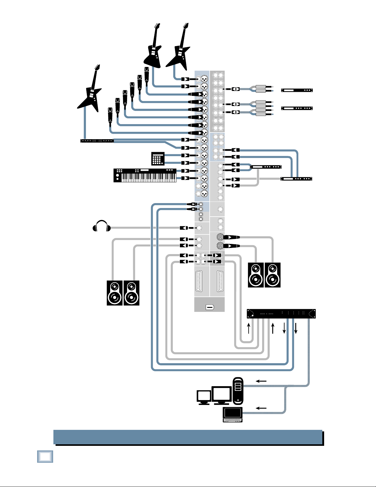
This hookup diagram demonstrates how
you can do a live multitrack recording
using the RECORDING OUTs or the optional FireWire card.
The RECORDING OUTs provide an
analog balanced direct output for each
channel, and the FireWire card provides
a digital direct output for each channel.
Electric Guitar
Vocal Mics
Stereo Guitar Effects
Keyboard or other
line level input
(record)
Drum
Machine
In
Headphones
Out
(play)
1
2
3
4
5
6
7
8
9
10
11
12
13
14
15
16
R
L
L
R
2
1
2
3
4
5
CHANNEL INSERTS
6
CHANNEL INPUTS
7
8
9
10
11
AUX RETURNS
12
13
14
AUX
15
16
IN-TAPE-OUT
MONO
PHONES
OUT
MAIN
CNTRL ROOM
OUTPUTS
MAIN
SUB OUT
341
MAIN
RECORDING OUT
1-8
RECORDING OUT
FIREWIRE
(OPTION)
1
2
3
4
5
6
7
8
L
1
R
L
2
R
SEND
OUT
OUT
OUT
INSERTS
9-16
9
10
11
12
13
14
15
16
L
3
R
L
4
R
1
2
3
4
5
6
Mono EQ
L
R
L
R
Mono Compressor
In
Out
In
Stereo Compressor
Out
In
Out
Mono EQ
Mono Power
Amplifier
In
Stereo Compressor
Out
In
Out
Multi Effect
Processor
Stage Monitors
Mono Power
Amplifier
Stage Monitors
Stereo EQ
Stereo Power
Amplifier
16 Channels + L/R Mix
2 Channels
Digital Multitrack
Hard Disk Recorder
SELECT
Left PA Speaker
SELECTSELECTSELECT
Right PA Speake
Laptop Computer
Onyx 1640 Live Mix and Multitrack Recording
6
ONYX 1640
Bass Guitar Electric Guitar
Owner’s Manual
Electric Guitar
Vocal Mics
Stereo Guitar Effects
Keyboard or other
line level input
Drum
Machine
In
(record)
Powered
Studio Monitors
for Control Room
Out
(play)
1
2
3
4
5
6
7
8
9
10
10
11
11
12
12
13
14
14
15
15
16
16
R
L
L
R
341
2
1
1
2
2
3
3
4
4
5
5
CHANNEL INSERTS
6
6
CHANNEL INPUTS
7
7
8
8
L
9
1
R
L
2
AUX RETURNS
R
13
AUX
IN-TAPE-OUT
MONO
PHONES
OUT
MAIN
CNTRL ROOM
OUTPUTS
MAIN
SUB OUT
MAIN
RECORDING OUT
1-8
RECORDING OUT
FIREWIRE
(OPTION)
9
10
11
12
13
14
15
16
L
3
R
L
4
R
1
2
3
SEND
4
5
6
OUT
L
OUT
R
OUT
L
R
INSERTS
9-16
Mono Compressor
In
Out
In
Stereo Compressor
Out
In
Out
Digital Delay
Multi Effect
Processor
Powered
Studio Monitors
for Studio
SELECTSELECTSELECT
Digital Multitrack
Hard Disk Recorder
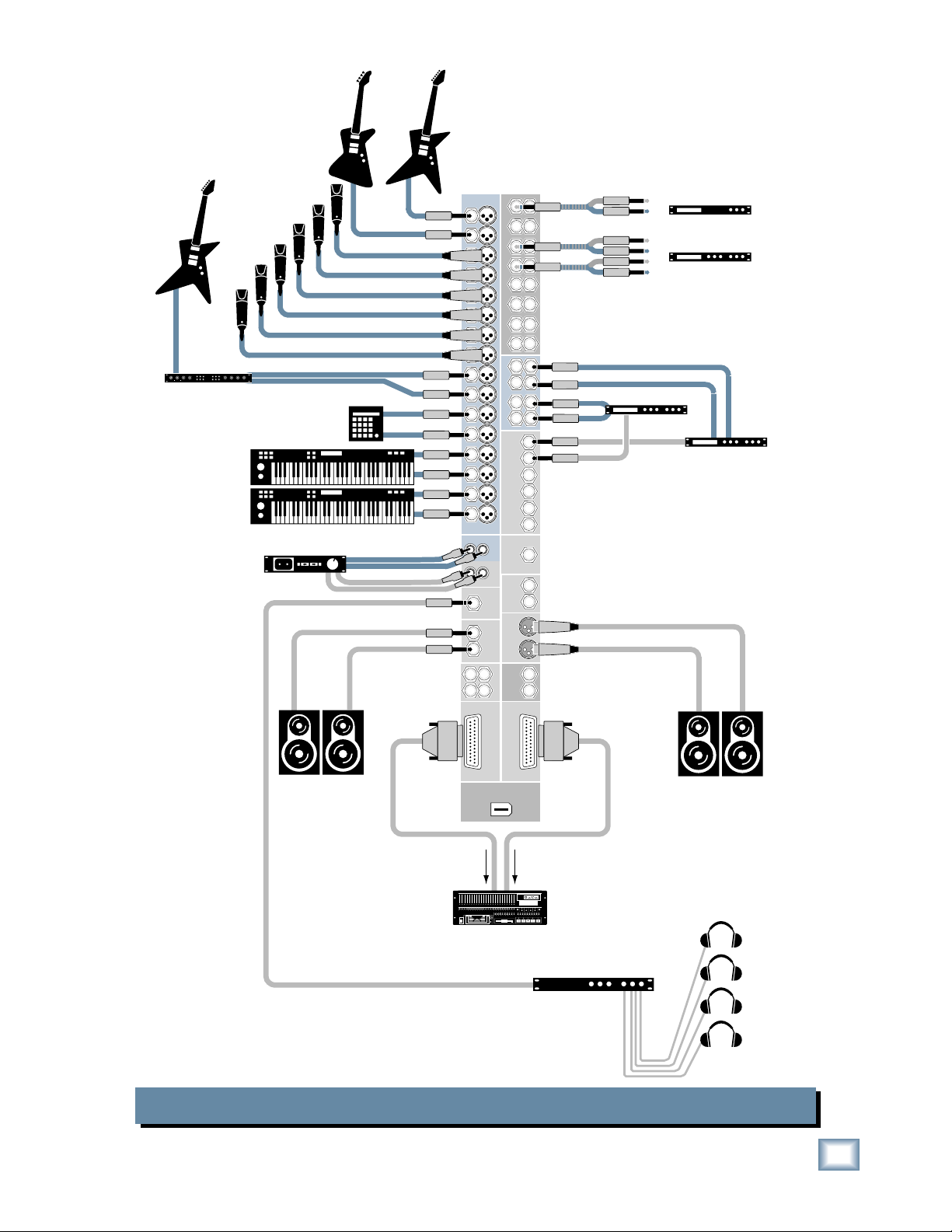
The RECORDING OUTs provide an analog balanced direct
output for each channel, tapped after the GAIN control but
before the EQ controls and channel INSERTS.
Onyx 1640 Multitrack Recording in a Studio (Tracking)
SELECT
Headphone Distribution
Amp
Headphones
for Studio
Owner’s Manual
7
Bass Guitar Electric Guitar
ONYX 1640
Stereo Guitar Effects
Electric Guitar
Headphones
Vocal Mics
Keyboard or other
line level input
Powered
Studio Monitors
for Control Room
Drum
Machine
1
2
3
4
5
6
7
8
9
10
11
12
13
14
15
16
L
R
L
R
2
1
2
3
4
5
CHANNEL INSERTS
6
CHANNEL INPUTS
7
8
9
10
11
AUX RETURNS
12
13
14
AUX
15
16
IN-TAPE-OUT
MONO
PHONES
OUT
MAIN
CNTRL ROOM
OUTPUTS
MAIN
SUB OUT
341
MAIN
RECORDING OUT
1-8
RECORDING OUT
FIREWIRE
(OPTION)
1
2
10
3
11
4
12
13
5
6
14
7
15
8
16
L
1
R
L
2
R
SEND
OUT
OUT
R
OUT
R
INSERTS
9-16
9
Mono Compressor
In
Out
In
Stereo Compressor
Out
In
Out
L
3
R
L
4
R
1
2
3
4
5
6
L
L
Digital Delay
Powered
Studio Monitors
for Studio
Multi Effect
Processor
Audio I/O for Workstation
In this hookup diagram, the tracking channels are
routed to the SUB 1-4 OUT. These are connected
the analog audio interface to your DAW or laptop.
A 2-track return is provided by the DAW (or laptop)
to the TAPE IN on the Onyx 1640 for playback of
the master mix.
Onyx 1640 Computer Recording
8
ONYX 1640
to
To Desktop
or
Laptop Computer
Electric Guitar
Stereo Guitar Effects
Keyboard or other
line level input
Drum
Mics
Submixer
for Drums
Headphones
Vocal Mics
1202-VLZPRO
(record)
Bass Guitar Electric Guitar
In
1
2
3
4
5
6
7
8
9
10
11
12
13
14
15
16
R
L
L
R
2
1
2
3
4
4
5
CHANNEL INSERTS
6
CHANNEL INPUTS
7
8
8
9
R
10
11
AUX RETURNS
12
13
14
AUX
15
16
IN-TAPE-OUT
MONO
PHONES
OUT
MAIN
CNTRL ROOM
OUTPUTS
MAIN
SUB OUT
341
MAIN
RECORDING OUT
1-8
RECORDING OUT
1
2
10
3
11
12
5
13
6
14
7
15
16
L
1
L
2
R
SEND
OUT
OUT
OUT
INSERTS
9-16
Owner’s Manual
Mono Compressor
9
L
3
R
L
4
R
1
2
3
4
5
6
L
R
L
R
In
Out
In
Stereo Compressor
Out
In
Out
Headphone Distribution
Amp
Headphones
for Studio
FIREWIRE
(OPTION)
Powered
Studio Monitors
for Control Room
16 Channels + L/R Mix
Powered
Studio Monitors
for Studio
2 Channels
Laptop Computer
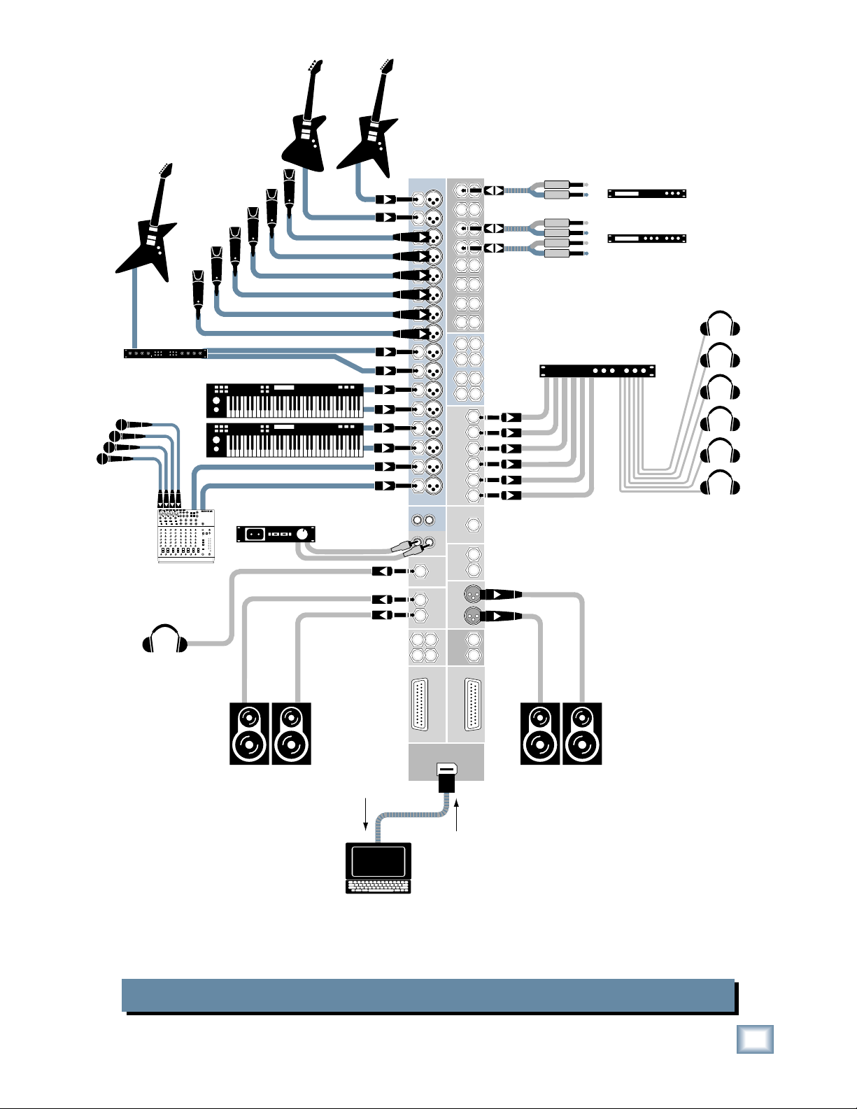
The optional FireWire card provides a digital direct output for each channel, as well as the L/R Mix.
Two tracks can be returned to the Onyx from the computer for playback monitoring in the Control
Room Outputs, or mixdown to two tracks at the TAPE OUT. The six AUX SENDS provide six separate mono headphone mixes to the talent.
Onyx 1640 Recording with FireWire to a Laptop
Owner’s Manual
9
Onyx 1640 Features
z
z
Channel Strips
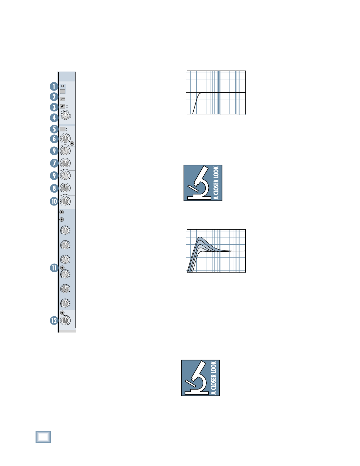
1
look alike and function identically with
ONYX 1640
48V
18dB/OCT
U
203040
U
+40dB
-20dB
GAIN
U
+15-15
2k
U
+15-15
400
U
+15-15
U
+15-15
OO
OO
OUT
IN
8k400
2k100
AUX
SEND
MAX
MAX
the following exception: Channels 1
and 2 have high-impedance instrument
75Hz
inputs in addition to the mic and line in-
MIC
HI-Z
puts so you can connect a guitar directly
to the mixer.
60
EQ
(except for the headphone jack) are locat-
HIGH
12kHz
ed on the rear rotopod. We’ll take a look at
them after we explore the front panel.
FREQ
HIGH
MID
1. 48V Phantom Power Switch
FREQ
phones require phantom power, which
LOW
MID
is a low-current DC voltage delivered to
the microphone on pins 2 and 3 of the
LOW
80Hz
XLR microphone connector. Push in the
48V button if your microphone needs
1
phantom power. An LED lights just
above the button to indicate that phantom power is active on that channel.
1
2
SM57 and SM58, do not require phantom
power. However, phantom power will not
3
OO
MAX
harm most dynamic microphones should
you accidentally plug one in while the
4
OO
MAX
OO
MAX
OO
MAX
phantom power is turned on. Be careful
with older ribbon microphones. Check
the manual for your microphone to fi nd
5
out for sure whether or not phantom
power can damage it.
6
PAN
[46] is turned down when connecting
R
L
microphones to the MIC Inputs, especially when phantom power is turned on,
to prevent pops from getting through to
the speakers.
All sixteen channels on the Onyx 1640
All the input and output connectors
Most professional condenser micro-
Dynamic microphones, like Shure’s
Note: Be sure the MAIN MIX fader
+15
+10
+5
0
–5
–10
–15
20Hz100
Low Cut
Hz
1k
Hz
We recommend that you
use the Low-Cut fi lter on
every microphone application except kick drum,
bass guitar, bassy synth
patches, or recordings of
earthquakes. These aside,
10kHz20k
H
there isn’t much down
there that you want to
hear, and fi ltering it out makes the low stuff you do want
much more crisp and tasty. Not only that, but the LowCut fi lter can help reduce the possibility of feedback in
live situations and it helps to conserve amplifi er power.
Another way to use the Low Cut fi lter
is in combination with the LOW EQ
on vocals during live performances.
Many times, bass shelving EQ can really benefi t voices. Trouble is, adding
LOW EQ also boosts stage rumble, mic
handling clunks, and breath pops. Low Cut removes all
those problems so you can add LOW EQ without losing a
woofer.
+15
+10
+5
0
–5
–10
–15
20Hz 100Hz 1kHz 10kHz 20kH
Low Cut with Low EQ Boosted
Here’s what the
combination of LOW EQ
and Low Cut looks like
in terms of frequency
curves.
3. MIC/HI-Z Switch (Channels 1 and 2)
Channels 1 and 2 have an extra button for switching
between the MIC and HI-Z inputs. When the button is out
(MIC), the XLR MIC input is used and the HI-Z input is
disconnected. When the button is pushed in (HI-Z), the
1/4
"
HI-Z input is used and the XLR MIC input is disconnected. The input stage of the HI-Z inputs is specially
designed for the high-impedance pickups on guitars.
2. Low-Cut Switch
The Low-Cut switch, often referred to as a high-pass
fi lter, cuts bass frequencies below 75 Hz at a rate of 18 dB
per octave.
10
ONYX 1640
Plugging a guitar into a lower-impedance
line input (like those on channels 3-16)
can result in the loss of high frequencies, causing an unnatural and dull
sound. Normally, you must use a direct
box between a guitar and a mixer’s input, which serves to convert the impedance of the guitar
from high to low. The HI-Z inputs on channels 1 and 2
make the need for a direct box unnecessary.
HOWEVER: The HI-Z inputs are unbalanced,
z
z
z
so if you’re
doing a live show and running a long cord between the
instrument and the mixer (say over 25 or 30
feet), it is
best to use a direct box with a balanced output to avoid
picking up noise over the length of the cord.
4. GAIN Control
If you haven’t already, please read “Set the Levels” on
page 5.
The GAIN control adjusts the input sensitivity of the mic
and line inputs. This allows the signal from the outside
world to be adjusted to optimal internal operating levels.
6. HIGH EQ
This control gives you
up to 15 dB boost or cut at
12 kHz, and it is also fl at
at the center detent. Use
it to add sizzle to cymbals,
and an overall sense of
transparency or edge to
the keyboards, vocals, guitar, and bacon frying. Turn
it down a little to reduce
sibilance, or to hide tape hiss.
+15
+10
–10
–15
+5
0
–5
20Hz100
High EQ
Owner’s Manual
Hz
1k
Hz
10kHz20k
H
If the signal is plugged into the XLR jack, there is 0 dB
of gain (unity gain) with the knob turned all the way
down, ramping up to 60 dB of gain fully up.
When connected to the 1/4" jack, there is 20 dB of
attenuation all the way down, and 40 dB of gain fully up,
with a “U” (unity gain) mark at about 10:00.
5. EQ IN/OUT Switch
This is a true hardware bypass of the Perkins EQ circuitry to insure that there is no coloration of the signal
if the EQ is not needed. When this button is out, the EQ
controls have no effect on the signal. You can use this
switch to make an A/B comparison between the EQ’d
signal and the signal without EQ.
We have completely redesigned the
EQ circuits in the Onyx Series of
mixers, based on the designs of Cal
Perkins, an industry-leader in audio
engineering for over three decades
and long-time Mackie collaborator.
This “neo-classic” design provides the sweet musicality
of the British EQ
boost and cut with optimum Q
(in other words, it gives you plenty of control and is
pleasing to the ear!).
The 4-band equalization has LOW shelving at 80 Hz,
LOW MID peaking, sweepable from 100 Hz to 2 kHz,
HIGH MID peaking, sweepable from 400 Hz to 8 kHz,
and HIGH shelving at 12 kHz. “Shelving” means that the
circuitry boosts or cuts all frequencies past the specifi ed frequency. For example, rotating the LOW EQ knob
15 dB to the right boosts bass frequencies starting at 80
Hz
and continuing on down to the lowest note you ever
heard. “Peaking” means that the frequencies around the
center frequency are less affected by the EQ the further
away they are.
sound, while still maintaining 15 dB of
and minimum phase shift
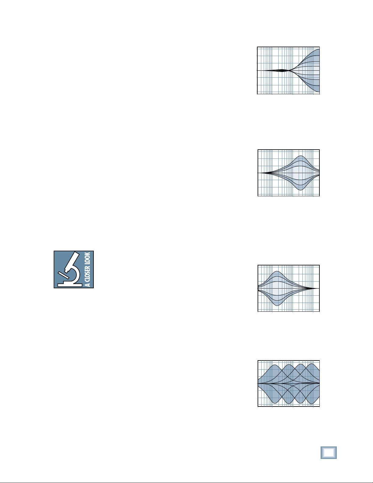
7. HIGH MID EQ
Short for “midrange,”
this knob provides 15 dB
of boost or cut centered
at the frequency determined by its FREQ [9]
knob. Midrange EQ is
often thought of as the
most dynamic because the
frequencies that defi ne any
+15
+10
+5
0
–5
–10
–15
20Hz100
Hz
High Mid EQ
1k
Hz
particular sound are almost always found in this range.
The HIGH MID EQ range (400 Hz to 8 kHz) includes
the female vocal range as well as the fundamentals and
harmonics for many instruments.
8. LOW MID EQ
This is a second midrange EQ control that provides 15 dB of boost or cut
centered at the frequency
determined by its FREQ
knob. It extends down to
100 Hz, which includes
the male vocal range and
the fundamentals of some
lower instruments (guitar, lower brass).
+15
+10
+5
0
–5
–10
–15
20Hz100
Hz
Low Mid EQ
1k
Hz
9. FR EQ
This knob ranges from
100 Hz to 2 kHz for the
LOW MID EQ, and 400
Hz to 8 kHz for the HIGH
MID EQ. This determines
the center frequency for
the EQ fi lter, and allows
you to zero in on the
precise narrow band of
frequencies you want to have affected by the LOW MID
and HIGH MID EQ.
+15
+10
+5
0
–5
–10
–15
20Hz 100Hz 1kHz 10kHz 20kHz
Mid EQ Freq Sweep
10kHz20k
10kHz20k
H
H
Owner’s Manual
11
 Loading...