

Mackie 1604-VLS PRO Owner's Manual
1604-VLZ PRO
16-CHANNEL
MIC/LINE MIXER
OWNER’S MANUAL
120 VAC 50/60 Hz 20W
1A/250V SLO-BLO
UTILISE UN FUSIBLE DE RECHANGE DE MÊME TYPE. DEBRANCHER AVANT DE REMPLACER LE FUSIBLE
UTILISE UN FUSIBLE DE RECHANGE DE MÊME TYPE. DEBRANCHER AVANT DE REMPLACER LE FUSIBLE
INSERT
LINE
BAL
UNBAL
MIC 16
M
I
C
R
D
X
16-CHA NNEL MIC/ LINE MIXER
WITH PREMIUM XDR
TRIM
d
B
0
V
1
-
G
A
C
I
I
N
M
060
-45dB
+15dB
AUX
U
1
OO
+15
U
2
OO
+15
PRE
U
3
OO
+15
U
4
OO
+15
5/6
SHIFT
EQ
U
+15-15
U
+15-15
800
8k
100
U
+15-15
LOW CUT
75 Hz
18dB/OCT
PAN
LR LR LR LR LR LR LR LR LR LR LR LR LR LR LR LR
1
MUTE
-
SOLO
1–2
3–4
L - R
OOOOOOOOOOOOOOOOOOOOOOOOOOOOOOOO
PHANTOM
POWER
ON
ON
CAUTION:
TO REDUCE THE RISK OF
FIRE REPLACE WITH SAME
TYPE FUSE AND RATING
INSERT
INSERT
LINE
LINE
16
15
BAL
BAL
UN-
UN-
BAL
BAL
MIC 15 MIC 14
M
M
I
I
C
C
R
R
P
P
R
E
1604-VL ZPRO
TRIM TRIM TRIM TRIM TRIM TRIM TRIM TRIM TRIM TRIM TRIM TRIM TRIM TRIM TRIM
1234 5 6 7 8 9 10 11 12 13
d
0
1
-
C
I
M
060
+15dB
AUX
U
12121212121212121212121212121
OO
U
OO
PRE PRE
U
5
3
OO
U
6
4
OO
5/6
SHIFT
EQ
HI
U
12k
U
MID
800
2k200
LOW
U
80Hz
LOW CUT
75 Hz
18dB/OCT
PAN
2
MUTE
OL
20
D
R
X
E
TM
MIC PREAMPLIFIERS
B
V
G
A
I
N
-45dB
+15dB
AUX
+15
+15
5
3
+15
6
4
+15
SHIFT
EQ
HI
12k
+15-15
MID
+15-15
2k200
8k100
LOW
80Hz
+15-15
LOW CUT
75 Hz
18dB/OCT
PAN
3
MUTE
OL
20
SOLO
1–2
3–4
L - R
d
0
1
-
G
C
I
M
060
U
OO
U
OO
U
OO
U
OO
5/6
U
U
800
U
P
D
R
X
B
V
A
I
N
-45dB
+15dB
AUX
+15
+15
5
3
+15
6
4
+15
SHIFT
EQ
HI
12k
+15-15
MID
+15-15
2k200
8k100
LOW
80Hz
+15-15
LOW CUT
75 Hz
18dB/OCT
PAN
4
MUTE
OL
20
SOLO
1–2
3–4
L - R
MAIN INSERT
MAIN OUT
BAL/UNBAL
RING RETURN)
L
MONO
R
OO
+6
INSERT
LINE
14 13
BAL
BAL
UN-
UN-
BAL
BAL
MIC 13
M
I
C
R
P
D
R
X
E
E
DESIGNED BY MACKOIDS IN WOODINVILLE, WA, USA • COPYRIGHT ©1998 • THE FOLLOWING ARE TRADEMARKS OR REGISTERED TRADEMARKS OF MACKIE DESIGN INC.: "MACKIE", "VLZ", "XDR", AND THE "RUNNING MAN" FIGURE • US PATENT NUMBER 29/049,129
d
d
B
B
0
0
V
V
1
1
-
-
G
G
A
A
C
C
I
I
I
I
N
N
M
M
060
060
-45dB
-45dB
+15dB
AUX
U
U
OO
OO
+15
+15
U
U
OO
OO
+15
+15
PRE PRE PRE PRE PRE PRE PRE PRE PRE PRE PRE
U
U
5
5
3
OO
OO
+15
+15
U
U
6
6
4
OO
OO
+15
+15
5/6
5/6
SHIFT
EQ
HI
HI
U
U
12k
12k
+15-15
+15-15
U
U
MID
MID
+15-15
+15-15
800
800
2k200
2k200
8k100
8k100
LOW
LOW
U
U
80Hz
80Hz
+15-15
+15-15
LOW CUT
75 Hz
18dB/OCT
PAN
5
MUTE
OL
OL
-
-
20
20
SOLO
SOLO
1–2
1–2
3–4
3–4
L - R
L - R
TAPE
(TIP SEND
INPUT
L
L
R
R
INSERT
INSERT
LINE
LINE
12 11 10
BAL
UNBAL
MIC 12 MIC 11
M
I
C
R
R
P
D
D
R
X
X
E
d
d
B
B
0
0
V
V
1
1
-
-
G
G
A
A
C
C
I
I
I
N
M
M
060
060
-45dB
-45dB
+15dB
+15dB
AUX
AUX
U
U
OO
OO
+15
+15
U
U
OO
OO
+15
+15
U
U
5
3
3
OO
OO
+15
+15
U
U
6
4
4
OO
OO
+15
+15
5/6
5/6
SHIFT
SHIFT
EQ
EQ
HI
U
U
12k
+15-15
+15-15
U
U
MID
+15-15
+15-15
800
800
2k200
8k100
LOW
U
U
80Hz
+15-15
+15-15
LOW CUT
LOW CUT
75 Hz
75 Hz
18dB/OCT
18dB/OCT
PAN
PAN
6
7
MUTE
MUTE
OL
20
SOLO
1–2
3–4
L - R
TAPE
OUTPUT
L
R
M
I
C
P
R
E
I
N
AUX
5
3
6
4
EQ
HI
12k
MID
2k200
8k100
LOW
80Hz
LOW CUT
18dB/OCT
PAN
MUTE
OL
20
SOLO
1–2
3–4
L - R
SUB OUT
C-R OUT
BAL/UNBAL
BAL/UNBAL
3
d
0
1
-
C
I
M
060
+15dB
U
OO
U
OO
U
OO
U
OO
5/6
SHIFT
U
U
800
U
75 Hz
9
MUTE
42
INSERT
BAL
UNBAL
MIC 9
M
I
C
R
D
X
B
V
G
A
I
N
-45dB
AUX
+15
+15
5
3
+15
6
4
+15
EQ
HI
12k
+15-15
MID
+15-15
2k200
8k100
LOW
80Hz
+15-15
LOW CUT
18dB/OCT
PAN
MUTE
OL
20
SOLO
1–2
3–4
L - R
TRACK
1
1
(MONO)
INSERT
876
9
LINELINE
BAL
UNBAL
MIC 8
M
I
C
R
P
P
D
R
R
X
E
E
d
d
B
B
0
0
V
V
1
1
-
-
G
G
A
A
C
C
I
I
I
I
N
N
M
M
060
060
-45dB
-45dB
+15dB
+15dB
AUX
U
U
OO
OO
+15
+15
U
U
OO
OO
+15
+15
U
U
5
3
OO
OO
+15
+15
U
U
6
4
OO
OO
+15
+15
5/6
5/6
SHIFT
SHIFT
EQ
HI
U
U
12k
+15-15
+15-15
U
U
MID
MID
+15-15
+15-15
800
800
2k200
2k200
100
8k
8k100
LOW
LOW
U
U
80Hz
80Hz
+15-15
+15-15
LOW CUT
75 Hz
75 Hz
18dB/OCT
PAN
10
11
MUTE
OL
OL
-
-
20
20
SOLO
SOLO
1–2
1–2
3–4
3–4
L - R
L - R
TRACK
TRACK
3
2
L
R
INSERT
LINE
BAL
UNBAL
MIC 10
M
I
C
R
P
D
R
X
E
TM
EXTENDED DYNAMIC RANGE MIC PREAMPLIFIERS ARE PROPRIETARY TO MACKIE DESIGNS, INC.
XDR
d
B
0
V
1
-
G
A
C
I
I
N
M
060
-45dB
+15dB
AUX
U
OO
+15
U
OO
+15
U
5
3
OO
+15
U
6
4
OO
+15
5/6
SHIFT
EQ
HI
U
12k
+15-15
U
MID
+15-15
800
2k200
8k100
LOW
U
80Hz
+15-15
LOW CUT
75 Hz
18dB/OCT
PAN
8
OL
20
SOLO
1–2
3–4
L - R
L
R
BAL
UNBAL
MIC 7
X
UUUUUUUUUUUU
+15dB
AUX
5
3
6
4
SHIFT
EQ EQ
HI
12k
100
LOW CUT
75 Hz
18dB/OCT
PAN
12
MUTE
AUX RETURN
BAL/UNBAL
INSERT
LINE
M
R
D
d
0
1
-
G
C
I
M
060
U
OO
U
OO
U
OO
U
OO
5/6
U
U
800
U
L
(MONO)
R
I
C
P
R
E
B
V
A
I
N
-45dB
+15
+15
+15
+15
+15-15
MID
+15-15
2k200
8k
LOW
80Hz
+15-15
OL
20
SOLO
1–2
3–4
L - R
TRACK
4
BAL
UNBAL
M
060
+15dB
AUX
5
3
6
4
5/6
SHIFT
HI
12k
100
LOW CUT
75 Hz
18dB/OCT
PAN
13
MUTE
234
L
L
(MONO)
R
R
INSERT
LINE
MIC 6 MIC 5
M
R
D
X
d
B
0
V
1
-
G
A
C
I
I
N
-45dB
U
OO
+15
U
OO
+15
U
OO
+15
U
OO
+15
U
+15-15
U
+15-15
800
8k
U
+15-15
OL
-
SOLO
1–2
3–4
L - R
TRACK
5
AUX SEND
BAL/UNBAL
5
1
64
INSERT
5
LINE
BAL
BAL
UN-
UN-
BAL
BAL
M
I
I
C
C
R
P
P
D
R
R
X
E
E
14
15 16
d
d
B
B
0
0
V
V
1
1
-
-
G
G
A
A
C
C
I
I
I
I
N
N
M
M
060
060
-45dB
-45dB
+15dB
+15dB
AUX
AUX
U
U
OO
OO
+15
+15
U
U
OO
OO
+15
+15
PRE
U
U
5
5
3
3
OO
OO
+15
+15
U
U
6
6
4
4
OO
OO
+15
+15
5/6
5/6
SHIFT
SHIFT
EQ
EQ
HI
HI
U
U
12k
12k
+15-15
+15-15
U
U
MID MID MID MID
+15-15
+15-15
800
800
2k200
LOW
80Hz
20
2k200
2k200
100
100
8k
8k
LOW
LOW
U
U
80Hz
80Hz
+15-15
+15-15
LOW CUT
LOW CUT
75 Hz
75 Hz
18dB/OCT
18dB/OCT
PAN
PAN
14
15
MUTE
MUTE
OL
OL
-
-
20
20
SOLO
SOLO
1–2
1–2
3–4
3–4
L - R
L - R
TRACK
TRACK
7
6
DIRECT OUT
BAL/UNBAL
75
1
3
64
8
2
INSERT
INSERT
INSERT
4321
LINE
MIC 4
M
I
C
R
P
D
R
X
E
d
B
0
V
1
-
G
A
C
I
I
N
M
UUUU
060
-45dB
+15dB
AUX
U
OO
+15
U
2
OO
+15
PRE
U
5
3
OO
+15
U
6
4
OO
+15
5/6
SHIFT
EQ
HI
U
12k
+15-15
U
+15-15
800
8k100
U
+15-15
LOW CUT
75 Hz
18dB/OCT
PAN
16
MUTE
LINE
BAL
UNBAL
MIC 3
M
I
C
R
P
D
R
X
E
1604-VL ZPRO
16-CHANNEL MIC / LINE MIXER
WITH PREMIUM XDR
U
1
OO
+10
U
2
OO
+10
AUX
SEND
1
5
SOLO
2
SOLO
6
PWR
PHAN
HI
12k
OO
MAX
CTL ROOM / PHONES
TAPE
SUBS 1–2
2k200
LOW
SUBS 3–4
80Hz
MAIN MIX
CTL ROOM
SOURCE
ASSIGN TO MAIN MIX
LEFT
RIGHT
1234
OL
20
BAL
UNBAL
1
2
3
4
LEFT
RIGHT
LINE
MIC 2
M
I
C
R
P
D
R
X
E
TM
MIC PREAMPLIFIERS
U
OO
+20
U
OO
+20
U
OO
+20
U
OO
+20
STEREO AUX RETURN
U
OO
+20
TAPE IN
TAPE TO
MAIN MIX
OO
MAX
SOLO
MODE
(AFL)
NORMAL
(PFL)
LEVEL SET
LEFT
RIGHT
BAL
UNBAL
1
2
ASSIGN OPTIONS
MAIN MIX
TO SUBS
C-R / PHNS
ONLY
LEVEL
SET
LEFT
RIGHT
RUDE
SOLO
LIGHT
SOLO
1–2
3–4
L - R
TRACK
8
1
3
2
INSERT
LINE
MIC 1
M
I
C
R
P
D
R
X
E
16151413121110987654321
12V
0.5A
LAMP
U
TO AUX
SEND 1
OO
+15
EFFECTS TO
MONITORS
U
TO AUX
SEND 2
OO
+15
1–2
3–4
RETURNS
SOLO
LEFT RIGHT
0 dB=0 dBu
28
10
7
4
2
0
2
4
7
10
20
30
PHONES
MAIN
MIX
dB
dB
10
10
5
5
U
U
5
5
10
10
20
20
30
30
40
40
50
50
60
60
OO
OO
CAUTION AVIS
RISK OF ELECTRIC
RISQUE DE
CAUTION: TO REDUCE THE RISK OF ELECTRIC SHOCK
NO USER-SERVICEABLE PARTS INSIDE
REFER SERVICING TO QUALIFIED PERSONNEL
ATTENTION: POUR EVITER LES RISQUES DE CHOC
ELECTRIQUE, NE PAS ENLEVER LE COUVERCLE. AUCUN
ENTRETIEN DE PIECES INTERIEURES PAR L'USAGER. CONFIER
L'ENTRETIEN AU PERSONNEL QUALIFIE.
AVIS: POUR EVITER LES RISQUES D'INCENDIE OU
D'ELECTROCUTION, N'EXPOSEZ PAS CET ARTICLE
The lightning flash with arrowhead symbol within an equilateral
triangle is intended to alert the user to the presence of uninsulated
"dangerous voltage" within the product's enclosure, that may be
of sufficient magnitude to constitute a risk of electric shock to persons.
Le symbole éclair avec point de flèche à l'intérieur d'un triangle
équilatéral est utilisé pour alerter l'utilisateur de la présence à
l'intérieur du coffret de "voltage dangereux" non isolé d'ampleur
suffisante pour constituer un risque d'éléctrocution.
The exclamation point within an equilateral triangle is intended to
alert the user of the presence of important operating and maintenance
(servicing) instructions in the literature accompanying the appliance.
Le point d'exclamation à l'intérieur d'un triangle équilatéral est
employé pour alerter les utilisateurs de la présence d'instructions
importantes pour le fonctionnement et l'entretien (service) dans le
livret d'instruction accompagnant l'appareil.
DO NOT OPEN
CHOC
NE PAS OUVRIR
DO NOT REMOVE COVER (OR BACK)
A LA PLUIE OU A L'HUMIDITE
SHOCK
ELECTRIQUE
SAFETY INSTRUCTIONS
1. Read Instructions — All the safety and operation instructions should be
read before this Mackie product is operated.
2. Retain Instructions — The safety and operating instructions should be kept
for future reference.
3. Heed Warnings — All warnings on this Mackie product and in these operating
instructions should be followed.
4. Follow Instructions — All operating and other instructions should be
followed.
5. Water and Moisture — This Mackie product should not be used near water
– for example, near a bathtub, washbowl, kitchen sink, laundry tub, in a wet
basement, near a swimming pool, swamp or salivating St. Bernard dog, etc.
6. Cleaning — Clean only with a dry cloth.
7. Ventilation — This Mackie product should be situated so that its
location or position does not interfere with its proper ventilation. For
example, the Component should not be situated on a bed, sofa, rug, or
similar surface that may block any ventilation openings, or placed in a
built-in installation such as a bookcase or cabinet that may impede the
flow of air through ventilation openings.
8. Heat — This Mackie product should be situated away from heat sources
such as radiators, or other devices which produce heat.
9. Power Sources — This Mackie product should be connected to a power
supply only of the type described in these operation instructions or as marked
on this Mackie product.
10 . Power Cord Protection — Power supply cords should be routed so that
they are not likely to be walked upon or pinched by items placed upon or
against them, paying particular attention to cords at plugs, convenience
receptacles, and the point where they exit this Mackie product.
11 . Object and Liquid Entry — Care should be taken so that objects do not
fall on, and liquids are not spilled into, this Mackie product.
12 . Damage Requiring Service — This Mackie product should be serviced
only by qualified service personnel when:
A. The power-supply cord or the plug has been damaged; or
B. Objects have fallen, or liquid has spilled into this Mackie
product; or
C. This Mackie product has been exposed to rain; or
D. This Mackie product does not appear to operate normally or
exhibits a marked change in performance; or
E. This Mackie product has been dropped, or its chassis damaged.
13 . Servicing — The user should not attempt to service this Mackie product
beyond those means described in this operating manual. All other servicing
should be referred to the Mackie Service Department.
14 . To prevent electric shock, do not use this polarized plug with an
extension cord, receptacle or other outlet unless the blades can be fully
inserted to prevent blade exposure.
Pour prévenir les chocs électriques ne pas utiliser cette fiche polariseé avec un
prolongateur, un prise de courant ou une autre sortie de courant, sauf si les
lames peuvent être insérées à fond sans laisser aucune pariie à découvert.
15 . Grounding or Polarization — Precautions should be taken so that the
grounding or polarization means of this Mackie product is not defeated.
16 . Power Precautions — Unplug this Mackie product during lightning storms
or when unused for long periods of time. Note that this Mackie product is not
completely disconnected from the AC mains service when the power switch is
in the OFF position.
17 . This apparatus does not exceed the Class A/Class B (whichever is
applicable) limits for radio noise emissions from digital apparatus as set out in the
radio interference regulations of the Canadian Department of Communications.
ATTENTION —Le présent appareil numérique n’émet pas de bruits
radioélectriques dépassant las limites applicables aux appareils numériques de
class A/de class B (selon le cas) prescrites dans le règlement sur le brouillage
radioélectrique édicté par les ministere des communications du Canada.
18 .
Exposure to extremely high noise levels may cause permanent hearing
loss. Individuals vary considerably in susceptibility to noise-induced hearing loss,
but nearly everyone will lose some hearing if exposed to sufficiently intense
noise for a period of time. The U.S. Government’s Occupational Safety and
Health Administration (OSHA) has specified the permissible noise level exposures
shown in the following chart.
According to OSHA, any exposure in excess of these permissible limits could
result in some hearing loss. To ensure against potentially dangerous exposure to
high sound pressure levels, it is recommended that all persons exposed to equipment capable of producing high sound pressure levels use hearing protectors
while the equipment is in operation. Ear plugs or protectors in the ear canals or
over the ears must be worn when operating the equipment in order to prevent
a permanent hearing loss if exposure is in excess of the limits set forth here.
Duration Per Day Sound Level dBA, Typical
In Hours Slow Response Example
8 90 Duo in small club
692
4 95 Subway Train
397
2 100 Very loud classical music
1.5 102
1 105 Tami screaming at Adrian about deadlines
0.5 110
0.25 or less 115 Loudest parts at a rock concert
WARNING — To reduce the risk of fire or electric shock,
do not expose this appliance to rain or moisture.
2

READ THIS PAGE!!!
We realize that you must have a powerful
hankerin’ to try out your new 1604-VLZ
you might be one of those people who never
reads manuals. Either way, all we ask is that
you read this page NOW, and the rest can wait
until you’re good and ready. But do read it —
you’ll be glad you did.
PRO. Or
LEVEL-SETTING PROCEDURE
Message to seasoned pros: do NOT set levels
using the old “Turn the trim up until the clip
light comes on, then back off a hair” trick. When a
Mackie Designs mixer clip light comes on, you
really are about to clip.
This procedure really works — it assures
low noise and high headroom. Please read on.
It’s not even necessary to hear what you’re doing to set optimal levels. But if you’d like to: Plug
headphones into the
then set the
quarter of the way up.
The following steps must be performed one
channel at a time:
1. Turn the
2. Be sure the
3. Set the
4. Connect the signal source to the
5. Engage (push in) the channel’s
6. Push in the
7. Play something into the selected input, at
8. Adjust the
9. If you’d like to apply some
10. Disengage that channel’s
11 . Repeat for each of channels 1–16.
C-R PHONES
controls fully down.
assignment switches are all disengaged.
EQ
LINE
channel input.
switch.
section (
LEVEL SET
real-world levels.
display on the meter stays around “0.”
(Only the left meter is active in the
Level-Setting Procedure.)
now and return to the previous step.
PHONES
TRIM, AUX
1–2, 3–4
knobs at the center detents.
MODE
switch in the output
LEVEL SET (PFL)
LED will light.
TRIM
control so that the
output jack,
knob about one-
send and fader
and
L–R
channel
MIC
SOLO
mode) — the
EQ
, do so
SOLO
switch.
or
Other Nuggets of Wisdom
For optimum sonic performance, the channel
faders and the
U
” (unity gain) markings.
the “
Always turn the
ROOM/PHONES
nections to and from your 1604-VLZ
If you shut down your equipment, turn off your
amplifiers first. When powering up, turn on your
amplifiers last.
Save the shipping box! You may need it
someday, and you don’t want to have to pay for
another one.
MAIN MIX
MAIN MIX
knob down before making con-
fader should be set near
fader and
PRO.
CTL
INSTANT MIXING
Here’s how to get going
right away, assuming you own a
microphone and a keyboard:
1. Plug your microphone into Channel 1’s
input.
2. Turn on the 1604-VLZ
3. Perform the Level-Setting Procedure .
4. Connect cords from the
your amplifier.
5. Hook up speakers to the amp and turn it on.
6. Set channel 1’s fader to the “ U” mark.
7. Engage (push in) Channel 1’s
8. Set the
9. Sing like a canary!
10. Plug your keyboard into channels 3 and 4.
11. Turn channel 3’s
12 . Set those faders to the “ U” mark.
13 .
14 .
15 . Play like a madman and sing like a canary!
MAIN MIX
way up.
channel 4’s
Perform the Level-Setting Procedure .
Engage the
It’s your first mix!
PAN
L-R
PRO.
MAIN OUT
L-R
fader one-quarter of the
PAN
knob fully left and
knob fully right.
switch on these channels.
MIC
jacks to
switch.
Please write your serial number here for
future reference (i.e. insurance claims,
tech support, return authorization, etc.):
Purchased at:
Part No. 0006982-90 Rev. A1 06/03
©2003 Mackie Designs Inc. All Rights Reserved.
Date of purchase:
3
INTRODUCTION
Thank you for choosing a Mackie Designs professional compact mixer. The 1604-VLZ PRO is
equipped with our new precision-engineered
TM
Extended Dynamic Range premium
XDR
studio-grade mic preamp featuring:
• Full gain range from 0 to 60dB
• +22 dBu line signal handling capability
• 130 dB dynamic range
• Distortion less than 0.0007%, 20Hz to 20kHz
• Bullet-proof RF rejection using DC pulse
transformer circuitry
Now that you have your 1604-VLZ PRO, find
out how to get the most from it. That’s where
this manual comes in.
HOW TO USE THIS MANUAL
Since many of you folks will want to hook up
your 1604-VLZ
you will encounter after the table of contents are
the ever popular hookup diagrams. These show
typical mixer setups for Record/Mixdown, Video,
Disc Jockey and Stereo PA. After this section is a
detailed tour of the entire mixer.
Every feature of the 1604-VLZ
described “geographically;” in other words, in
order of where it is physically placed on the
mixer’s top or rear panel. These descriptions are
divided into the first three manual chapters, just
as your mixer is organized into three distinct
zones:
1. PATCHBAY: The zillion jacks on the back
of the “pod.”
2. CHANNEL STRIP: The sixteen channel
strips on the left.
3. OUTPUT SECTION: The output section on
the right.
PRO immediately, the first pages
PRO will be
Whenever a specific 1604-VLZ
PRO component is mentioned, it’ll be in all capital letters
sans-serif type. That can help you find references to specific controls much faster, without
slowing you down as you read normally. For example: The quick brown fader jumped over the
RUDE SOLO LIGHT
.
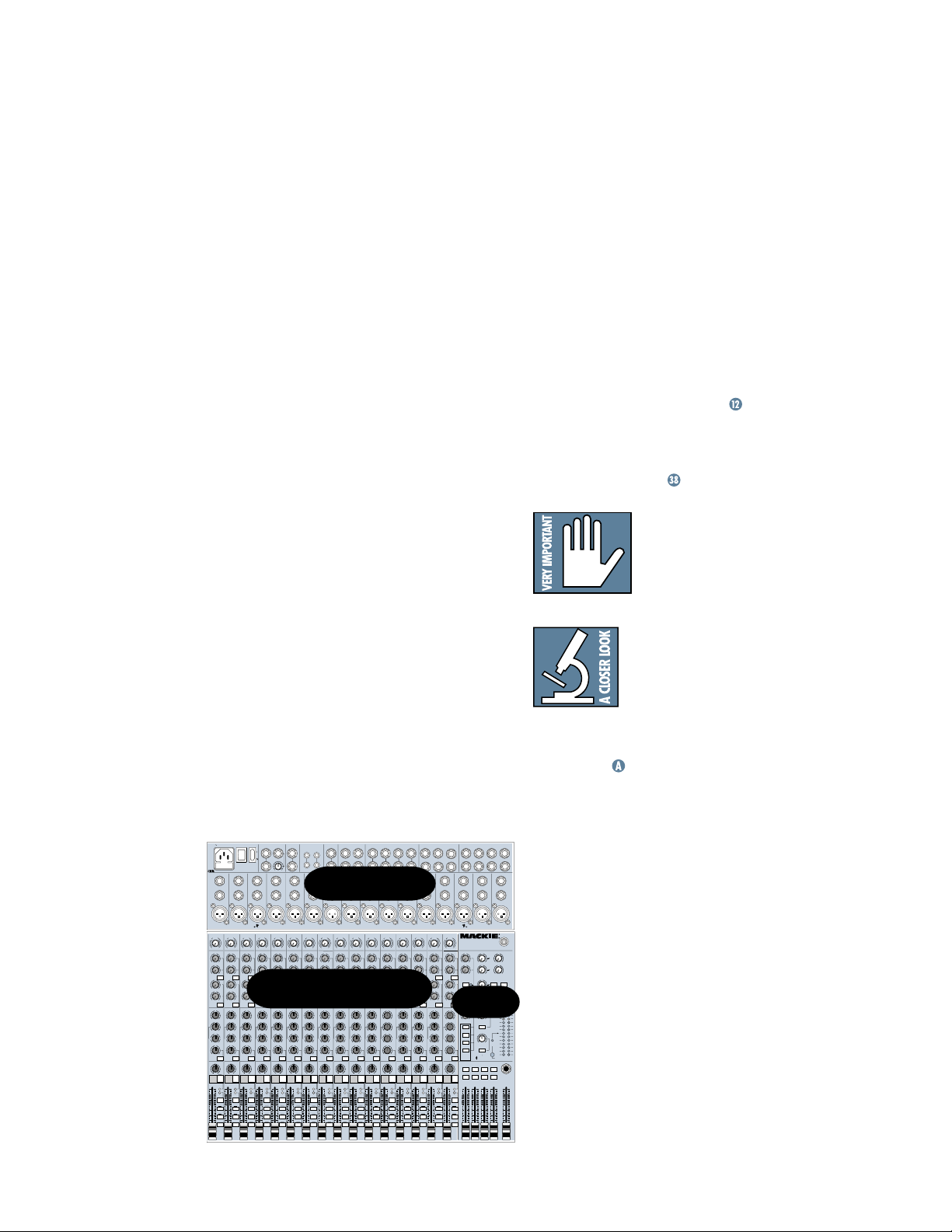
Throughout these chapters you’ll find illustrations, with each feature numbered. If you’re
curious about a feature, simply locate it on the
appropriate illustration, note the number attached to it, and find that number in the nearby
paragraphs or refer to the table of contents.
You’ ll also find cross-references to these numbered features within a paragraph. For instance, if
you see “To wire your own cables:
,” simply find
that number in the manual and you’ ve found your
answer. (These are not page numbers.)
You’ll also notice feature numbers just float-
ing in space, like this
. These numbers
direct you to relevant information.
This icon marks information that is critically
important or unique to the
1604-VLZ
PRO. For your
own good, read them and
remember them. They will be on the final test.
This icon will lead you to
in-depth explanations of features and practical tips. While
not mandatory, they’ll have
some valuable information.
A PLUG FOR THE CONNECTORS SECTION
Appendix is a section on connectors:
XLR connectors, balanced connectors, unbalanced connectors, special hybrid connectors.
120 VAC 50/60 Hz 20W
POWER
1A/250V SLO-BLO
ON
CAUTION:
TO REDUCE THE RISK OF
FIRE REPLACE WITH SAME
TYPE FUSE AND RATING
UTILISE UN FUSIBLE DE RECHANGE DE MÊME TYPE. DEBRANCHER AVANT DE REMPLACER LE FUSIBLE
INSERT
INSERT
LINE
LINE
16
BAL
BAL
UN-
UN-
BAL
BAL
MIC 16
MIC 15 MIC 14
M
M
I
I
C
C
R
R
P
P
D
D
R
X
X
E
TRIM
TRIMTRIMTRIMTRIMTRIMTRIMTRIMTRIMTRIMTRIMTRIMTRIMTRIMTRIMTRIM
1234 5 6 7 8 9 10 11 12 131415 16
d
d
B
B
0
0
V
V
1
1
-
-
G
G
A
A
C
C
I
I
I
I
N
N
M
M
060
060
+15dB -45dB
+15dB -45dB
AUX
AUX
AUX
U
U
1
12121212121212121212121212121
OO
OO
+15
+15
U
U
2
OO
OO
+15
+15
PRE
PRE PRE
U
U
5
5
3
3
3
OO
OO
+15
+15
U
U
6
6
4
4
4
OO
OO
+15
+15
5/6
5/6
SHIFT
SHIFT
EQ
EQ
EQ
HI
HI
U
U
12k
12k
+15-15
+15-15
U
U
MID
MID
+15-15
+15-15
800
800
2k200
2k200
8k
100
8k100
LOW
LOW
U
U
80Hz
80Hz
+15-15
+15-15
LOW CUT
LOW CUT
LOW CUT
75 Hz
75 Hz
18dB/OCT
18dB/OCT
18dB/OCT
PAN
PAN
PAN
LR LR LR LR LR LR LR LR LR LR LR LR LR LR LR LR
1
2
MUTE
MUTE
MUTE
OL
OL
-
-
20
20
SOLO
SOLO
1–2
1–2
3–4
3–4
L - R
L - R
OOOOOOOOOOOOOOOOOOOOOOOOOOOOOOOO
MAIN INSERT
MAIN OUT
PHANTOM
(TIP SEND
BAL/UNBAL
ON
RING RETURN)
L
L
MONO
R
R
OO
+6
INSERT
INSERT
INSERT
LINE
LINE
LINE
15 14 13 12 11 10
BAL
BAL
BAL
UN-
UN-
UN-
BAL
BAL
BAL
MIC 12 MIC 11
MIC 13
M
M
M
I
I
I
C
C
C
R
R
R
P
P
P
D
D
D
R
R
R
R
X
X
X
E
E
E
E
DESIGNED BY MACKOIDS IN WOODINVILLE, WA, USA • COPYRIGHT ©1998 • THE FOLLOWING ARE TRADEMARKS OR REGISTERED TRADEMARKS OF MACKIE DESIGN INC.: "MACKIE", "VLZ", "XDR", AND THE "RUNNING MAN" FIGURE • US PATENT NUMBER 29/049,129
d
d
d
d
B
B
B
B
0
0
0
0
V
V
V
1
-
G
A
C
I
I
N
M
060
+15dB -45dB
U
OO
+15
U
OO
+15
U
OO
+15
U
OO
+15
5/6
SHIFT
U
+15-15
U
+15-15
800
U
+15-15
75 Hz
3
V
1
1
1
-
-
-
G
G
G
A
A
A
C
C
C
I
I
I
I
I
I
N
N
N
M
M
M
060
060
060
+15dB -45dB
+15dB -45dB
+15dB -45dB
AUX
AUX
AUX
U
U
U
OO
OO
OO
+15
+15
+15
U
U
U
OO
OO
OO
+15
+15
+15
PRE PRE PRE PRE PRE PRE PRE PRE PRE PRE PRE
U
U
U
5
5
5
5
3
3
3
OO
OO
OO
+15
+15
+15
U
U
U
6
6
6
6
4
4
4
CHANNEL STRIPS
OO
OO
OO
+15
+15
+15
5/6
5/6
5/6
SHIFT
SHIFT
SHIFT
EQ
EQ
EQ
HI
HI
HI
HI
U
U
U
12k
12k
12k
12k
+15-15
+15-15
+15-15
U
U
U
MID
MID
MID
MID
+15-15
+15-15
+15-15
800
800
800
2k200
2k200
2k200
8k100
LOW
OL
20
SOLO
1–2
3–4
L - R
2k200
8k100
8k100
8k100
LOW
LOW
LOW
U
U
U
80Hz
80Hz
80Hz
80Hz
+15-15
+15-15
+15-15
LOW CUT
LOW CUT
LOW CUT
75 Hz
75 Hz
75 Hz
18dB/OCT
18dB/OCT
18dB/OCT
PAN
PAN
PAN
4
5
6
MUTE
MUTE
MUTE
OL
OL
OL
-
-
-
20
20
20
SOLO
SOLO
SOLO
1–2
1–2
1–2
3–4
3–4
3–4
L - R
L - R
L - R
SUB OUT
C-R OUT
TAPE
TAPE
BAL/UNBAL
BAL/UNBAL
OUTPUT
INPUT
3
1
L
L
L
R
42
R
R
INSERT
LINE
BAL
UNBAL
M
I
C
R
P
D
R
X
E
d
B
0
V
1
-
G
A
C
I
I
N
M
060
+15dB -45dB
AUX
AUX
U
OO
+15
U
OO
+15
U
5
3
3
OO
+15
U
6
4
4
OO
+15
5/6
SHIFT
EQ
EQ
HI
U
12k
+15-15
U
MID
+15-15
800
2k200
8k100
LOW
U
80Hz
+15-15
LOW CUT
LOW CUT
75 Hz
75 Hz
18dB/OCT
18dB/OCT
PAN
PAN
7
MUTE
MUTE
OL
20
SOLO
1–2
3–4
L - R
INSERT
INSERT
INSERT
98765
LINELINE
LINE
PATCHBAY
BAL
BAL
BAL
UN-
UN-
UN-
BAL
BAL
BAL
MIC 8
MIC 9
MIC 10
M
M
M
I
I
C
C
R
R
R
P
P
D
D
D
R
R
X
X
X
E
E
TM
EXTENDED DYNAMIC RANGE MIC PREAMPLIFIERS ARE PROPRIETARY TO MACKIE DESIGNS, INC.
XDR
d
d
d
B
B
B
0
0
0
V
V
V
1
1
1
-
-
-
-
G
G
G
A
A
A
C
C
C
I
I
I
I
I
I
N
N
N
M
M
M
060
+15dB -45dB
OO
OO
OO
OO
5/6
SHIFT
8
M
060
060
060
+15dB -45dB
+15dB -45dB
+15dB -45dB
AUX
AUX
AUX
U
U
U
OO
OO
OO
+15
+15
+15
U
U
U
OO
OO
OO
+15
+15
+15
U
U
U
5
5
5
3
3
3
OO
OO
OO
+15
+15
+15
U
U
U
6
6
6
4
4
4
OO
OO
OO
+15
+15
+15
5/6
5/6
5/6
SHIFT
SHIFT
SHIFT
EQ
EQ
EQ
HI
HI
HI
U
U
U
12k
12k
12k
+15-15
+15-15
+15-15
U
U
U
MID
MID
MID
+15-15
+15-15
+15-15
800
800
800
2k200
2k200
2k200
100
8k100
8k100
8k
LOW
LOW
LOW
U
U
U
80Hz
80Hz
80Hz
+15-15
+15-15
+15-15
LOW CUT
LOW CUT
LOW CUT
75 Hz
75 Hz
75 Hz
18dB/OCT
18dB/OCT
18dB/OCT
PAN
PAN
PAN
9
10
11
MUTE
MUTE
MUTE
OL
OL
OL
-
-
-
20
20
20
SOLO
SOLO
SOLO
1–2
1–2
1–2
3–4
3–4
3–4
L - R
L - R
L - R
1
I
C
0
1
C
I
800
P
R
E
d
B
V
G
A
I
N
U
+15
U
+15
U
+15
U
+15
U
+15-15
U
+15-15
8k100
LOW
U
+15-15
OL
-
SOLO
1–2
3–4
L - R
(MONO)
12k
MID
2k200
80Hz
20
L
R
BAL
UN-
BAL
AUX
5
3
6
4
EQ EQ
HI
LOW CUT
18dB/OCT
PAN
MUTE
UUUUUUUUUUUU
75 Hz
12
AUX RETURN
BAL/UNBAL
L
(MONO)
R
INSERT
LINE
MIC 7
M
I
C
R
P
D
R
X
E
d
B
0
V
1
-
G
A
C
I
I
N
M
060
+15dB -45dB
AUX
U
OO
+15
U
OO
+15
U
5
3
OO
+15
U
6
4
OO
+15
5/6
SHIFT
HI
U
12k
+15-15
U
MID
+15-15
800
2k200
100
8k
LOW
U
80Hz
+15-15
LOW CUT
18dB/OCT
PAN
OL
20
SOLO
1–2
3–4
L - R
234
L
L
(MONO)
R
R
INSERT
LINE
BAL
UN-
BAL
MIC 6
M
R
D
X
d
B
0
V
1
-
G
A
C
I
I
N
M
060
+15dB -45dB
U
OO
+15
U
OO
+15
U
OO
+15
U
OO
+15
5/6
SHIFT
U
+15-15
U
MID MID MID MID
+15-15
800
2k200
100
8k
LOW
U
80Hz
+15-15
75 Hz
13
MUTE
OL
20
SOLO
1–2
3–4
L - R
AUX SEND
BAL/UNBAL
5
1
64
INSERT
LINE
BAL
UN-
BAL
MIC 5
M
I
I
C
C
R
P
P
D
R
R
X
E
E
d
d
B
0
0
V
1
1
-
-
G
G
A
C
C
I
I
I
N
M
M
060
060
+15dB -45dB
+15dB -45dB
AUX
AUX
U
U
OO
OO
+15
U
U
OO
OO
+15
PRE
U
U
5
5
3
3
OO
OO
+15
U
U
6
6
4
4
OO
OO
+15
5/6
5/6
SHIFT
SHIFT
EQ
EQ
HI
HI
U
U
12k
12k
+15-15
U
U
+15-15
800
800
2k200
100
100
8k
LOW
U
U
80Hz
+15-15
LOW CUT
LOW CUT
75 Hz
75 Hz
18dB/OCT
18dB/OCT
PAN
PAN
14
15
MUTE
MUTE
OL
20
SOLO
1–2
3–4
L - R
4
BAL
UNBAL
B
V
A
I
N
+15
+15
+15
+15
+15-15
+15-15
2k200
8k
LOW
80Hz
+15-15
OL
20
SOLO
1–2
3–4
L - R
3
INSERT
LINE
MIC 4
M
I
C
R
P
D
X
M
UUUU
060
+15dB -45dB
AUX
OO
2
OO
PRE
5
3
OO
6
4
OO
5/6
SHIFT
EQ
HI
12k
LOW CUT
75 Hz
18dB/OCT
PAN
16
MUTE
R
E
0
1
-
C
I
800
4
d
B
V
G
A
I
N
U
+15
U
+15
U
+15
U
+15
U
+15-15
U
+15-15
8k100
U
+15-15
SOLO
TRACK8TRACK7TRACK6TRACK5TRACK4TRACK3TRACK2TRACK
2k200
LOW
80Hz
OL
20
1–2
3–4
L - R
1
2
BAL
UNBAL
5
6
HI
12k
WITH PREMIUM XDR
1
2
1
2
CTL ROOM / PHONES
INSERT
LINE
MIC 3
M
I
R
D
X
16-CHANNEL MIC/ LINE MIXER
OO
OO
AUX
SEND
SOLO
SOLO
PHAN
OO
TAPE
SUBS 1–2
SUBS 3–4
MAIN MIX
CTL ROOM
SOURCE
LEFT
RIGHT
DIRECT OUT
BAL/UNBAL
3
75
64
8
INSERT
INSERT
32
LINE
BAL
BAL
UN-
UN-
BAL
BAL
MIC 1
MIC 2
C
M
I
C
R
P
P
D
D
R
R
X
X
E
E
1604-VLZ PRO
TM
MIC PREAMPLIFIERS
U
U
U
1
1
OO
OO
+20
+10
U
U
U
2
2
OO
OO
+20
+10
U
ASSIGN OPTIONS
3
MAIN MIX
OO
+20
TO SUBS
U
4
C-R / PHNS
OUTPUT
OO
+20
ONLY
PWR
STEREO AUX RETURN
U
SECTION
OO
+20
MAX
TAPE IN
TAPE TO
MAIN MIX
OO
MAX
LEVEL
SET
SOLO
MODE
RUDE
NORMAL
(AFL)
SOLO
(PFL)
LEVEL SET
LIGHT
ASSIGN TO MAIN MIX
LEFT
LEFT
LEFT
RIGHT
RIGHT
RIGHT
1234
dB
10
5
U
5
10
20
30
40
50
60
1
More resources on our website @
2
www.mackie.com
1
LINE
M
I
C
R
P
R
E
THE GLOSSARY: A Haven of Non-Techiness For
The Neophyte
12V
0.5A
LAMP
+15
+15
1–2
3–4
RETURNS
SOLO
LEFT RIGHT
0 dB=0 dBu
PHONES
MAIN
OO
The "Glossary of Terms" is a fairly compre-
TO AUX
SEND 1
EFFECTS TO
MONITORS
TO AUX
SEND 2
hensive dictionary of pro-audio terms. If terms
like “clipping,” “noise floor,” or “unbalanced”
leave you blank, refer to this glossary for a
28
10
7
4
2
quick explanation.
0
2
4
7
10
20
30
ARCANE MYSTERIES ILLUMINATED
"Arcane Mysteries" discusses some of the down ’n’
MIX
dB
10
5
U
dirty practical realities of microphones, fixed installa-
5
10
20
30
tions, grounding, and balanced versus unbalanced
40
50
60
OO
lines. It’s a goldmine for the neophyte and even the
seasoned pro might learn a thing or two.

CONTENTS
LEVEL-SETTING PROCEDURE ............................ 3
INSTANT MIXING ............................................ 3
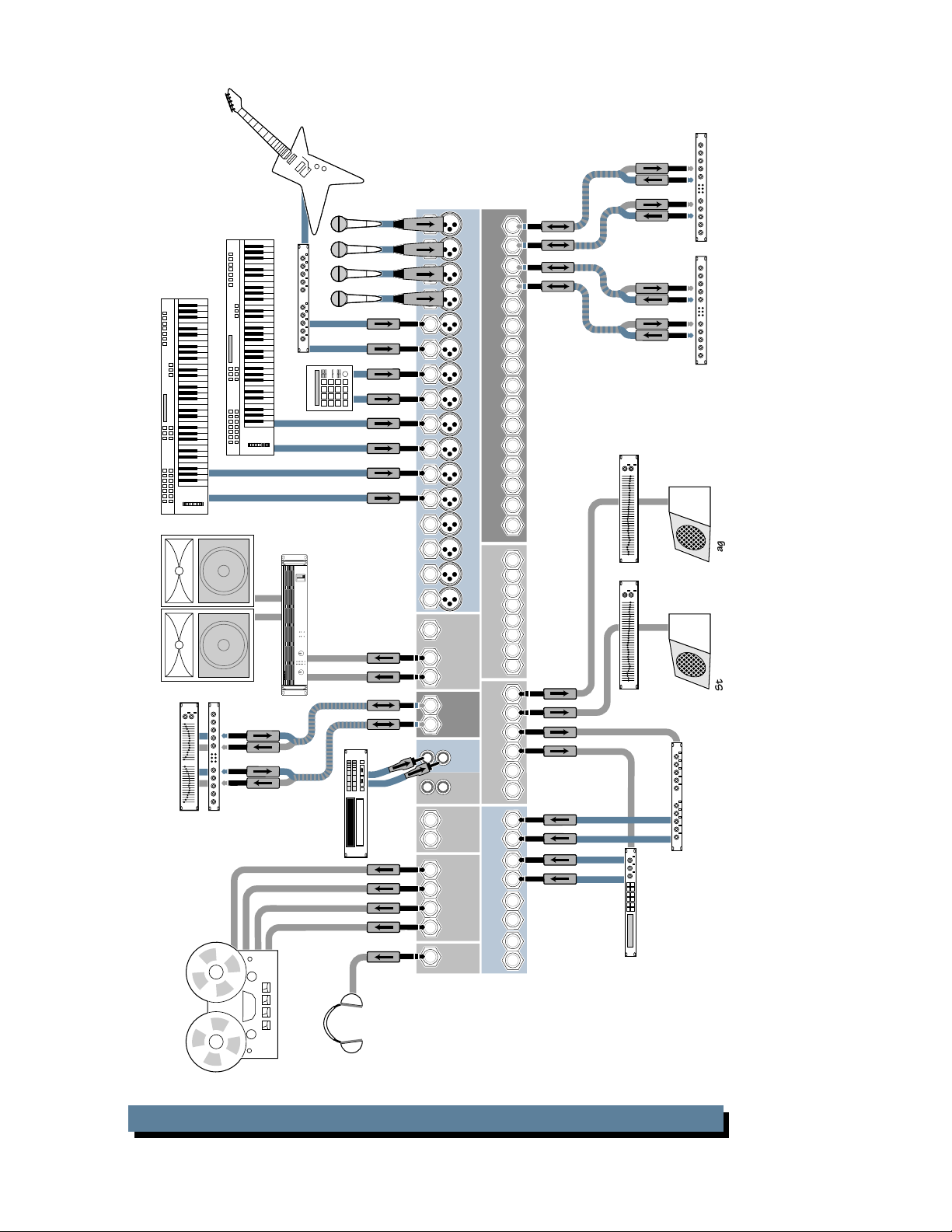
HOOKUP DIAGRAMS ....................................... 6
CONVERTING TO RACKMOUNT MODE .............. 9
PATCHBAY DESCRIPTION ............................... 10
E-Z INTERFACE ........................................ 10
MIC/LINE INPUTS ON EVERY CHANNEL.... 10
MIC INPUTS ............................................ 10
PHANTOM POWER .................................. 10
LINE INPUTS ........................................... 11
TRIM ...................................................... 11
INSERT ................................................... 11
DIRECT OUT ............................................ 11
SPLIT MONITORING ................................ 12
AUX SEND OUTPUTS ............................... 12
EFFECTS: SERIAL OR PARALLEL? ............... 13
AUX RETURN INPUTS .............................. 13
SUB OUTS ............................................... 13
C-R OUTS (CONTROL ROOM OUTPUTS) .... 14
PHONES OUTPUT .................................... 14
TAPE OUTPUT ......................................... 14
TAPE INPUT ............................................ 14
MAIN INSERT .......................................... 15
MAIN OUTS ............................................ 15
MONO OUTPUT....................................... 15
MONO LEVEL .......................................... 15
POWER CONNECTION .............................. 15
FUSE....................................................... 15
POWER SWITCH ...................................... 16
POWER LED ............................................ 16
PHANTOM SWITCH ................................. 16
PHANTOM LED ........................................ 16
BNC LAMP SOCKET ................................. 16
CHANNEL STRIP DESCRIPTION ....................... 17
“U” LIKE UNITY GAIN ............................. 17
FADER..................................................... 17
ASSIGN (1-2, 3-4, L-R) ........................... 17
SOLO ...................................................... 18
–20 (SOLO) LED ...................................... 18
OL (MUTE) LED ........................................ 18
MUTE ..................................................... 19
PAN........................................................ 19
3-BAND MID-SWEEP EQ .......................... 19
LOW CUT ................................................ 20
AUX ....................................................... 20
PRE ........................................................ 21
5/6 SHIFT .............................................. 21
OUTPUT SECTION DESCRIPTION ..................... 22
MAIN MIX FADER.................................... 22
VLZ MIX ARCHITECTURE ......................... 22
SUB FADERS............................................ 22
ASSIGN TO MAIN MIX ............................. 22
TAPE IN (LEVEL) ...................................... 23
TAPE TO MAIN MIX ................................. 23
SOURCE .................................................. 23
CTL ROOM/PHONES ............................... 23
MODE (NORMAL (AFL)/LEVEL SET (PFL)) ... 24
LEVEL SET LED ......................................... 24
SOLO (LEVEL) .......................................... 24
RUDE SOLO LIGHT................................... 24
METERS .................................................. 25
AUX TALK............................................... 25
AUX SEND (MASTER)............................... 25
AUX SENDS SOLO ................................... 26
AUX RETURNS (LEVEL) ............................ 26
EFFECTS TO MONITOR ............................. 26
MAIN MIX TO SUBS (AUX RET 3) ............. 26
1-2/3-4 (AUX RET 3) ............................. 26
C-R/PHNS ONLY (AUX RET 4) ................. 27
RETURNS SOLO....................................... 27
MODIFICATIONS.......................................... 27
1604-VLZ PRO BLOCK DIAGRAM ................... 28
GAIN STRUCTURE DIAGRAM.......................... 29
SPECIFICATIONS............................................ 30
SERVICE INFO ............................................... 31
APPENDIX A: CONNECTIONS ................................. 32
TRACK SHEET ....................................................... 36
COLOPHON .......................................................... 38
1604-VLZ PRO LIMITED WARRANTY .................... 39
5
21
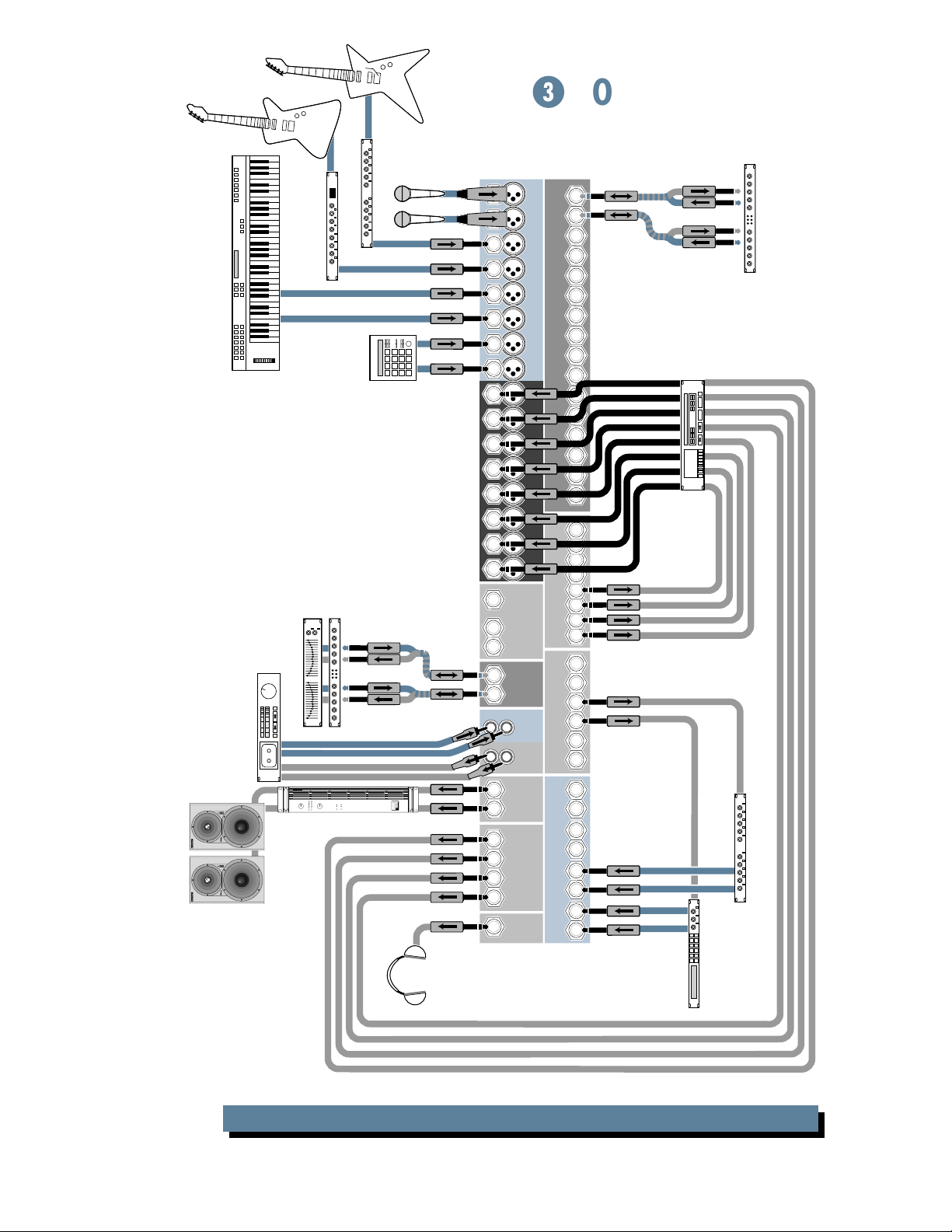
HOOKUP DIAGRAMS
Keyboard, or other line-level input
ON
OFF
OL
PWR
HIGH RESOLUTION
STUDIO MONITOR
ON
OFF
OL
PWR
Studio Monitors
HIGH RESOLUTION
STUDIO MONITOR
Stereo EQ w/Compressor
Cassette or DAT
CH
1
FULL SYMMETRY DUAL DIFFERENTIAL HIGH CURRENT DESIGN
Stereo Power Amplifier
Guitar Effects
Bass Preamp
Drum
Machine
out
in
out
in
CH
2
34
5
6
7
8
9
10
11
12
13
14
15
16
MONOSTEREO
LR
L
R
L
R
L
R
L
R
4
3
12
CHANNEL INSERTS
CHANNEL INPUTS
BAL/UNBAL
DIRECT OUT
BAL/UNBAL
MAIN OUT
MAIN
INSERT
BAL/UNBAL
IN
AUX SENDS
TAPE
OUT
TAPE
1
C/R OUT
BAL/UNBAL
2
3
AUX RETURNS
BAL/UNBAL
SUB OUTS
4
OUT
PHONES
Digital
8-track
16151413121110987654321
out
in
1
2
3
4
8-track outputs
5
6
7
8
12
3
4
5
6
L
R
L
R
L
R
LR
Stereo Compressor
Mono in / stereo out
Reverb
Digital Delay
1604-VLZ PRO 8-Track Tracking
6
Keyboard, or other line-level input
Keyboard, or other line-level input
Right PA Speaker
Left PA Speaker
out
in
out
in
Stereo EQ
Stereo
Compressor
r
e
d
r
o
c
e
R
Guitar Effects
Drum
Machine
Stereo
CH
2
FULL SYMMETRY DUAL DIFFERENTIAL HIGH CURRENT DESIGN
CH
1
NOTE: for mono PA, use
Power Amplifier
CD Player
21
34
5
6
7
8
9
CHANNEL INPUTS
10
11
12
13
14
15
16
mono output to feed FOH.
MONOSTEREO
LR
L
R
L
R
L
R
L
R
4
3
12
BAL/UNBAL
MAIN OUT
MAIN
INSERT
IN
TAPE
OUT
TAPE
C/R OUT
BAL/UNBAL
BAL/UNBAL
SUB OUTS
OUT
PHONES
CHANNEL INSERTS
16151413121110987654321
1
2
3
4
5
BAL/UNBAL
DIRECT OUT
6
7
8
12
3
4
BAL/UNBAL
AUX SENDS
5
6
L
1
R
L
2
R
L
3
AUX RETURNS
R
LR
4
Digital Delay
Mono EQMono EQ
Stereo CompressorStereo Compressor
Stage Monitor
Stage Monitor
Mono in / stereo out
Reverb
k
c
a
r
t
i
t
l
u
M
Optional Live Recording
1604-VLZ PRO Stereo P.A.
7

Video Deck
21
Video Deck
Video Deck
out
Multi-VCR
Video Switcher
with Time Code
ON
OFF
OL
PWR
HIGH RESOLUTION
STUDIO MONITOR
ON
OFF
OL
PWR
Studio Monitors
HIGH RESOLUTION
STUDIO MONITOR
Keyboard, or other line-level input
CD Player
Sampler
Interface
CH
2
FULL SYMMETRY DUAL D IFFERENTIAL HIGH CURRENT DESIGN
CH
1
in
Stereo
Power Amplifier
Master
Video
34
5
6
7
8
9
10
11
12
13
14
15
16
MONOSTEREO
LR
L
R
L
R
L
R
L
R
4
3
12
CHANNEL INSERTS
CHANNEL INPUTS
BAL/UNBAL
DIRECT OUT
BAL/UNBAL
MAIN OUT
MAIN
INSERT
BAL/UNBAL
IN
AUX SENDS
TAPE
OUT
TAPE
1
C/R OUT
BAL/UNBAL
2
3
AUX RETURNS
BAL/UNBAL
SUB OUTS
4
OUT
PHONES
16151413121110987654321
1
2
3
4
5
6
7
8
12
3
4
5
6
L
R
Mono in / stereo out
Reverb
L
R
L
R
LR
Digital Delay
Stereo Compressor
Computer
with Audio Card
1604-VLZ PRO Video Setup
8
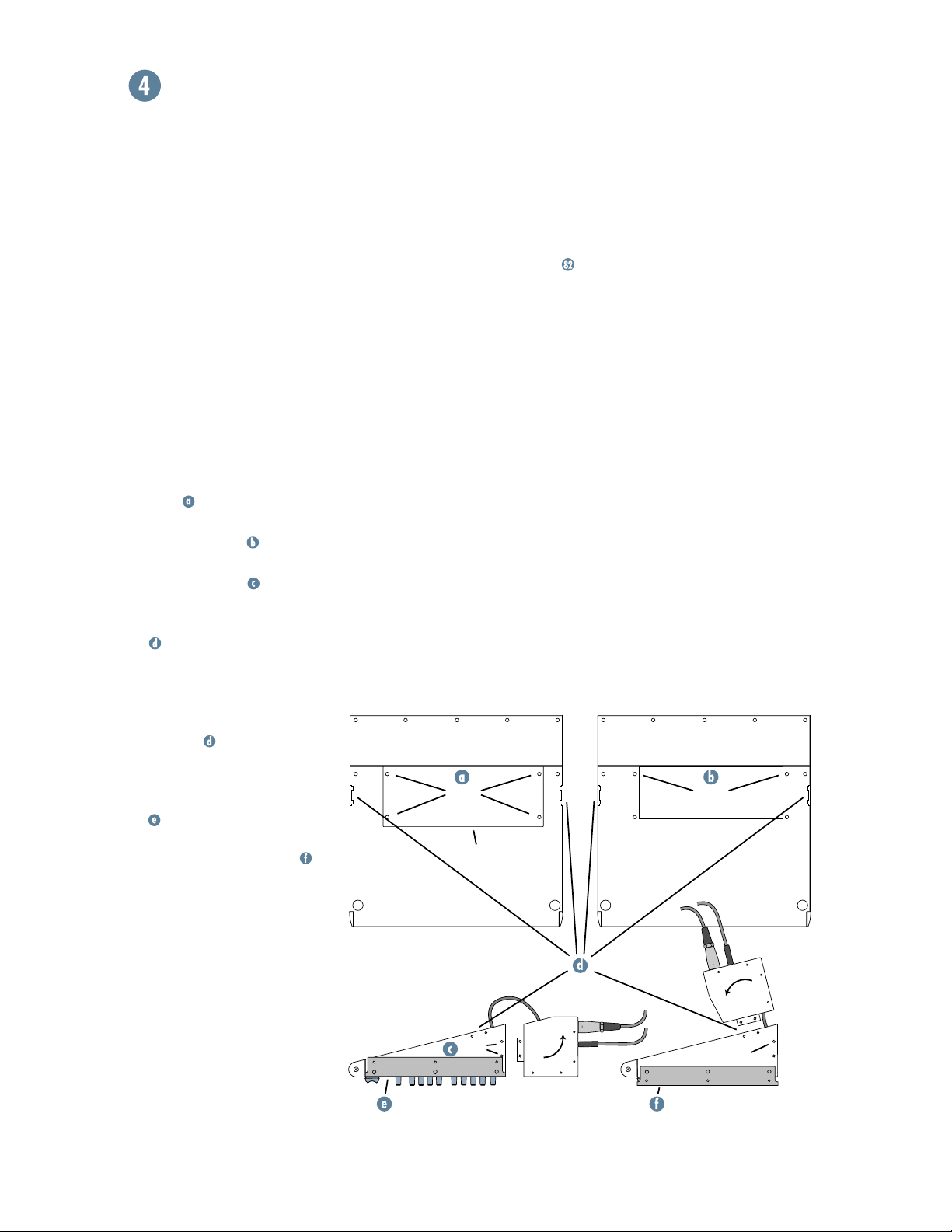
CONVERTING TO RACKMOUNT MODE
Not only is the new 1604-VLZ PRO a compact,
professional-quality tabletop mixer, it’s rackmountable! Its unique rotating input pod
makes this possible.
One of the things that revolutionized the compact
mixer industry was the “convertible pod” found
on the original, classic CR-1604. Using an ordinary Phillips screwdriver, the mixer could be
converted from desktop mode (as it comes from
the factory) to rackmount mode.
Fear not. We wouldn’t dare take that feature out
of the New Improved 1604-VLZ
PRO. It’s still
there and still takes just a few minutes with your
trusty screwdriver. Here’s how it’s done:
1. Remove ALL the cords from the mixer —
audio, power, lamps, everything.
2. Place the mixer, face down, on a clean soft
surface, like a blanket or very large dog.
3. Remove the four screws securing the cable
cover
and set the plate aside.
4. Replace two of the screws; the ones at the pod
end of the mixer
.
5. Remove two pod-mounting screws on each
side of the mixer
.
6. Gently pull the pod away from the slots, rotate it,
and place it, tabs first, into the rackmount tabs
, located on the underside of the main chassis. Be careful not to constrict or pinch any of
the ribbon or power cables.
7. Carefully install the podmounting screws in their new
locations
.
8. Install the rack ears that came
with the mixer. They can be installed in either of two depths:
mixer’s surface flush with
the rack rails, like ordinary
rackmount equipment, or
mixer’s surface sunken into the
rack, to protect the knobs from
being bumped.
An optional accessory called the ROTOPODVLZ is available and can be used in desktop or
rackmount installations. It will put the patchbay
jacks on the same plane as all the knobs, buttons and
faders. This is a lifesaver in applications that demand
frequent repatching, and costs a heck of a lot less than
an external patchbay, not to mention all the interface and patch cords:
. Please visit your dealer
for more exciting details. Be sure to order the
“VLZ” version so you don’t end up with the one for
the classic CR-1604!
remove
screws
remove
plate
replace
screws
flush mount
remove
screws
rotate
pod
rackmount
tab slots
sunken
9
replace
screws
PATCHBAY DESCRIPTION
120 VAC 50/60 Hz 20W
1A/250V SLO-BLO
UTILISE UN FUSIBLE DE RECHANGE DE MÊME TYPE. DEBRANCHER AVANT DE REMPLACER LE FUSIBLE
UTILISE UN FUSIBLE DE RECHANGE DE MÊME TYPE. DEBRANCHER AVANT DE REMPLACER LE FUSIBLE
INSERT
POWER
ON
CAUTION:
TO REDUCE THE RISK OF
FIRE REPLACE WITH SAME
TYPE FUSE AND RATING
INSERT
PHANTOM
ON
At the risk of stating the obvious, this is
where you plug everything in: microphones,
line-level instruments and effects, and the ultimate destination for your sound: a tape
recorder, PA system, etc. A few of the features
described in this section are on top of the
mixer, but most are out back on the “pod.”
E-Z INTERFACE
Concerned about levels,
balancing, impedances, polarity, or other interface
goblins? Don’t be. On your
1604-VLZ
PRO, you can patch anything almost
anywhere, with nary a care. Here’s why:
• Every input and output is balanced
(except insert, phones and RCA jacks).
• Every input and output will also accept
unbalanced lines (except XLR jacks).
• Every input is designed to accept virtually
any output impedance.
• The main left and right mix outputs can
deliver 28dBu into as low as a 600 ohm load.
• All the other outputs can deliver 22dBu
into as low as a 600 ohm load.
• All the outputs are in phase with the inputs.
All we ask is that you perform the Level-Setting
Procedure
every time you patch in a new
sound source. So stop worrying and start mixing!
MIC/LINE INPUTS ON EVERY CHANNEL
The original CR-1604 had six mic/line channels
and ten line-only channels. That was fine for most
applications, but live sound users were forced to
go out and buy the XLR-10 mic input add-on
module. No more. Each and every channel on the
New Improved 1604-VLZ
PRO has the legendary
Mackie mic/line input circuit. It’s like getting a
free XLR-10 with your mixer!
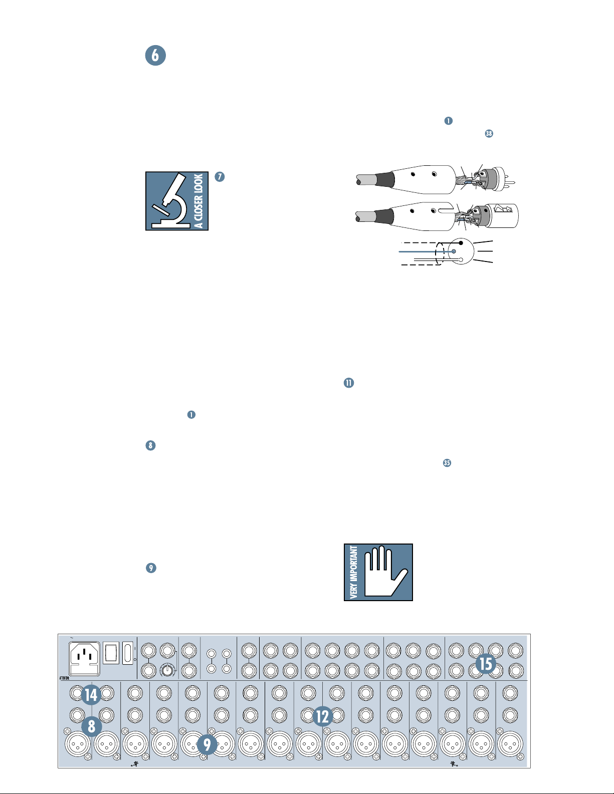
MIC INPUTS
We use phantom-powered, balanced microphone inputs just like the big studio megaconsoles, for exactly the same reason: This
kind of circuit is excellent at rejecting hum
INSERT
MAIN OUT
BAL/UNBAL
L
R
INSERT
MONO
MAIN INSERT
TAPE
(TIP SEND
INPUT
RING RETURN)
L
L
R
OO
+6
R
INSERT
INSERT
TAPE
OUTPUT
C-R OUT
BAL/UNBAL
L
R
INSERT
L
R
SUB OUT
BAL/UNBAL
3
42
INSERT
and noise. You can plug in almost any kind of
mic that has a standard XLR-type male mic
connector. Always be sure to perform the
Level-Setting Procedure
nals are routed from these inputs:
. To learn how sig-
. If you
wire your own, connect them like this:
COLD
COLD
2
HOT
1
3
1
3
2
HOT
1
3
2
SHIELD
COLD
HOT
SHIELD
SHIELD
Pin 1 = ground or shield
Pin 2 = positive (+ or hot)
Pin 3 = negative (– or cold)
Professional ribbon, dynamic, and condenser
mics will all sound excellent through these inputs. The 1604-VLZ
PRO’s mic inputs will handle
almost any kind of mic level you can toss at
them, without overloading.
PHANTOM POWER
Most condenser mics require phantom power,
where the mixer sends low-current DC voltage to
the mic’s electronics through the same wires
1
2
INSERT
MIC
75
8
PRO’s phantom
PHANTOM
input jacks if
DIRECT OUT
BAL/UNBAL
3
64
INSERT
INSERT
1
2
that carry audio. The 1604-VLZ
power is globally controlled by the
switch on the rear panel .
Semipro condenser mics often have batteries to accomplish the same thing. “Phantom”
owes its name to an ability to be “unseen” by
®
dynamic mics (Shure
SM57/SM58, for instance) that don’t need external power and
aren’t affected by it anyway.
Unless you know for certain it is safe to do so,
never plug single-ended
(unbalanced) microphones, instruments or
electronic devices into the
the phantom power is on.
AUX RETURN
(MONO)
BAL/UNBAL
INSERT
(MONO)
23
L
L
L
(MONO)
R
R
R
INSERT
4
L
R
1
INSERT
1
AUX SEND
BAL/UNBAL
5
64
INSERT
3
INSERT
16
15 14 13
BAL
BAL
UN-
UN-
BAL
BAL
MIC 16
MIC 15 MIC 14
M
M
I
I
C
C
R
R
P
P
D
D
R
X
R
X
E
E
BAL
BAL
UN-
UN-
BAL
BAL
MIC 13
M
M
R
D
X
I
I
C
C
R
P
P
D
R
R
X
E
E
12 11 10
BAL
BAL
UN-
UN-
BAL
BAL
MIC 12 MIC 11
M
I
C
R
P
D
R
X
E
LINE
BAL
UNBAL
MIC 10
M
M
I
I
C
R
D
X
C
R
P
P
D
R
R
X
E
E
98765
LINELINE
BAL
BAL
BAL
UNBAL
MIC 9
M
I
C
R
P
D
R
X
E
UN-
UN-
BAL
BAL
MIC 7
MIC 8
M
I
C
R
P
D
D
R
X
X
E
LINE
M
I
C
R
P
R
E
LINE
BAL
UNBAL
MIC 6 MIC 5
M
I
C
R
P
D
R
X
E
LINE
BAL
UN-
BAL
M
I
C
R
P
D
R
X
E
4321
LINE
BAL
BAL
UN-
UN-
BAL
BAL
MIC 3
MIC 4
M
I
C
R
P
D
R
X
X
E
LINE
LINE
BAL
UNBAL
MIC 2
M
I
C
M
I
R
D
C
R
P
P
D
R
R
X
E
E
LINE
BAL
UNBAL
MIC 1
M
I
C
R
P
D
R
X
E
LINE
LINE
LINE
LINE
LINE
LINE
10
TM
XDR
DESIGNED BY MACKOIDS IN WOODINVILLE, WA, USA • COPYRIGHT ©1998 • THE FOLLOWING ARE TRADEMARKS OR REGISTERED TRADEMARKS OF MACKIE DESIGN INC.: "MACKIE", "VLZ", "XDR", AND THE "RUNNING MAN" FIGURE • US PATENT NUMBER 29/049,129
EXTENDED DYNAMIC RANGE MIC PREAMPLIFIERS ARE PROPRIETARY TO MACKIE DESIGNS, INC.
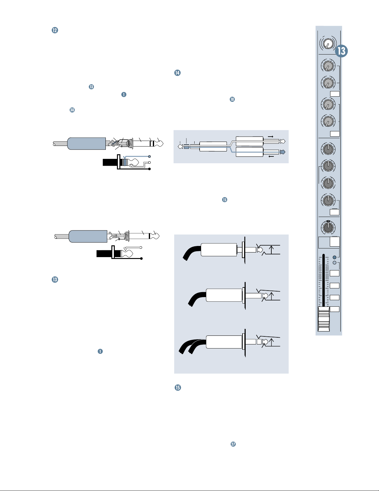
LINE INPUTS
These 1/4" jacks share circuitry (but not
phantom power) with the mic preamps. You
can use these inputs for virtually any signal
you’ll come across, from instrument levels as
low as –50dB to operating levels of –10dBV to
+4dBu, as there is 60dB of gain available via
TRIM
the
the
knob . Always be sure to perform
Level-Setting Procedure
.
To learn how signals are routed from these
inputs:
inputs, use a
. To connect balanced lines to these
1
/4" tip-ring-sleeve (TRS) plug,
the type found on some stereo headphones:
TIPSLEEVE
SLEEVERING
TIP
RING
RING
TIP
SLEEVE
Tip = positive (+ or hot)
Ring = negative (– or cold)
Sleeve = shield or ground
To connect unbalanced lines to these in-
1
puts, use a
/4" mono (TS) phone plug or
standard instrument cable:
SLEEVE
TIP
Tip = signal (+)
Sleeve = ground
TIPSLEEVE
TIP
SLEEVE
TRIM
Yes it’s true, these controls are not located
in the patchbay section at all. They’re found
along the top row of knobs in the channel strip
section. But their purpose is so closely linked
MIC
and
LINE
with the
couldn’t bear to separate them. Here’s why:
Every time you plug something into a
LINE
input jack, you should perform the
Setting Procedure
basically “how to use the
TRIM
adjusts the input sensitivity of the
MIC
and
LINE
inputs. This allows signals from
the outside world to be adjusted to optimal
internal operating levels.
Through the XLR jack (
0dB of gain with the knob fully down, ramping
to 60dB of gain fully up.
Through the
of attenuation fully down and 45dB of gain fully
U
up, with a “
” (unity gain) mark at 10:00.
input jacks that we
, and that procedure is
TRIM
knob.”
MIC
1
/4" input (
LINE
), there is 15dB
MIC
or
Level-
), there will be
This 15dB of attenuation can be very handy
when you are inserting a signal that is very hot,
or you want to add a lot of EQ gain, or both.
Without this “virtual pad,” a scenario like that
might lead to channel clipping.
INSERT
These 1/4" jacks are for connecting serial
effects processors such as compressors, equaliz-
. The
INSERT
ers, de-essers, or filters
TRIM
after the
EQ, LOW CUT,
control, but before the channel’s
fader and
MUTE
point is
controls. Insert
cables must be wired thusly:
ring
tip
This plug connects to one of the
mixer’s Channel Insert jacks.
sleeve
(TRS plug)
SEND to processor
RETURN from processor
“tip”
“ring”
Tip = send (output to effects device)
Ring = return (input from effects device)
Sleeve = common ground
Even though channels 1–8 already have
DIRECT OUT
be used as channel direct outputs; post-
LOW CUT
preyou can use the
Direct out with no signal interruption to master.
(TIP = SEND to effect, RING = RETURN from effect.)
jacks ,
INSERT
jacks can also
TRIM
, and pre-EQ. Here’s three ways
INSERT
jacks:
MONO PLUG
Channel Insert jack
Insert only to first “click.”
MONO PLUG
Channel Insert jack
Direct out with signal interruption to master.
Insert all the way in to the second “click.”
STEREO
PLUG
For use as an effects loop.
Channel Insert jack
DIRECT OUT
Found only on channels 1–8, these 1/4" jacks
deliver the signal from the very end of the
TRIM
channel path; post-
, post-fader and post-
CUT
, post-EQ, post-
MUTE
. They are the
key player in “split monitoring,” making the
1604-VLZ
wire your own cables:
PRO perfect for an 8-track studio. To
.
LOW
TRIM
1
d
B
0
V
1
-
G
A
C
I
I
N
M
U
060
-45dB
+15dB
AUX
U
1
OO
+15
U
2
OO
+15
PRE
U
5
3
OO
+15
U
6
4
OO
+15
5/6
SHIFT
EQ
HI
U
12k
+15-15
U
MID
+15-15
800
2k200
8k
100
LOW
U
80Hz
,
LOW CUT
75 Hz
18dB/OCT
PAN
MUTE
LR
1
+15-15
OL
-
20
SOLO
1–2
3–4
L - R
OO
11
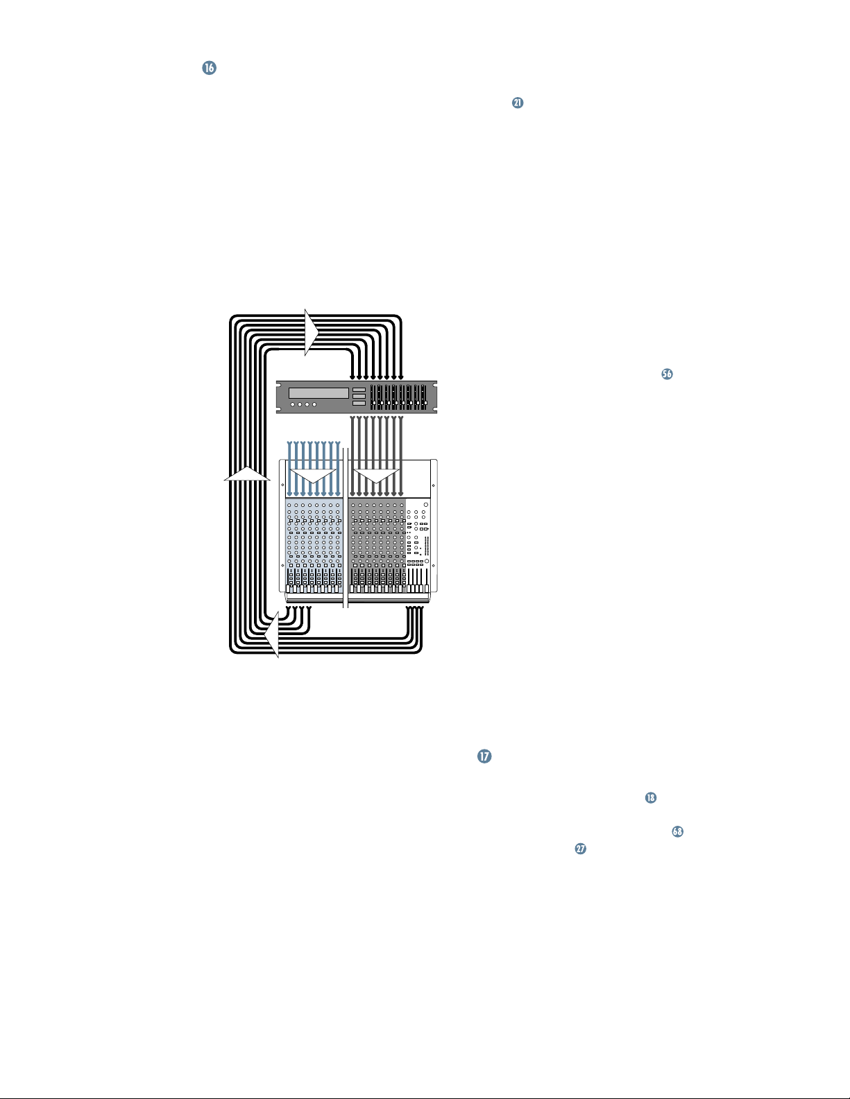
SPLIT MONITORING
With split monitoring, you use the first eight
channels for your sound sources: vocal mics,
drum mics, keyboard/synth outputs, guitar
effects outputs, that sort of thing. From there,
the channels manipulate the sound, but are
not assigned to the output section. Instead,
they’re patched from the channel’s
jacks to the corresponding multitrack
OUT
DIRECT OUT 1
input (
to multitrack input 1,
2 to 2, 3 to 3, etc.). The signals will now be recorded or pass directly through the multitrack,
depending on each track’s record-ready status.
multitrack
machine
sound sources
1–8 9–16
direct
outputs
The outputs of the multitrack are then
patched to the next eight
1604-VLZ
PRO (multitrack out 1 to
LINE
9, 2 to 10, 3 to 11, etc.). Aha! That’s why it says
TRACK 1
“
” next to channel 9’s fader, “
next to channel 10, and so forth. These channels (9–16) will be assigned to the mixer’s
output section, delivering the signals to their
ultimate destination, which may be your
mixdown 2-track, your control room system,
or your headphones.
DIRECT
group
outputs
inputs on the
LINE
TRACK 2
input
But let’s not forget that the 1604-VLZ
a 4-bus mixer. These buses lead to the
, and are designed to accomplish the
OUTS
task of getting channels to the multitrack without using the direct outputs.
For example, a channel is assigned to
SUB OUT 1. SUB OUT 1
’s output is patched to
multitrack input 1. From there, the multitrack
output goes to the mixer’s channel 9
as we just discussed. (Hot tip: To feed an 8-track
deck with 4 sub outputs, simply use Y-cords:
SUB OUT 1
6,
3
feeds 3 and 7, and 4 feeds 4 and 8. Tracks in
feeds tracks 1 and 5, 2 feeds 2 and
record mode will accept the signal, and tracks in
safe mode will ignore the signal.)
The advantages: You can assign any channel
to any track, without repatching. You can assign multiple channels to one track and control
the overall level of that subgroup
bounce tracks without this feature.
Perhaps the best method is to do both: Use
SUB OUTS
the
to feed multichannel submixes
(like a drum kit) to some of the tracks, and
DIRECT OUT
the
jacks to feed single-channel
signals (like bass guitar) to the other tracks.
The point is that you never listen directly to
the source channels (1–8). You listen to the
monitor channels (9–16) and they’re listening to
the multitrack that is listening to the source
channels. The main advantage is that you won’t
be forced to constantly repatch your multitrack
— just set it up and forget it. You’ll also know for
certain that the signals are indeed getting to the
multitrack, since you’re constantly listening to it.
Another method of interfacing a multitrack is
called inline monitoring, and requires a mixing
console dedicated to that, like the Mackie
8•Bus. Each of its channels is actually two channels: one carrying the mic/line sound source and
the other carrying the multitrack output.
”
AUX SEND OUTPUTS
These 1/4" jacks usually patch to the inputs
of your parallel effects devices
or to the inputs of your stage monitor amps. To learn how
signals are routed to these outputs:
your own cables:
.
PRO is
SUB
LINE
input,
. You can’t
. To wire
12
 Loading...