

MAC Audio CAP 1200F Owner's Manual
8. TECHNISCHE DATEN/BESONDERHEITEN
Kapazität: 1.2 Farad ±10%
Betriebsspannung: 12-14,8V DC Gleichspannung
Betriebstemperatur: -20 – +60 °C
E.S.R.: <0,004 Ohm @100Hz/25°C
Maße (Ø x H): 76 x 220 mm
Gewicht: 1,45 kg
• 3½-stellige digitale Spannungsanzeige mit roten LEDs
• 2 Status-LEDs (blau) zur Betriebszustandsanzeige
• Unterspannungswarnung bei Spannungen unter 10V
• Warnton bei Verpolung und Kurzschluss
• Alubecher aus gebürstetem Aluminium
• Stabile, vernickelte Inbus-Schraubanschlüsse im
Chrome-Look
• Schutzabdeckung aus durchsichtigem Kunststo
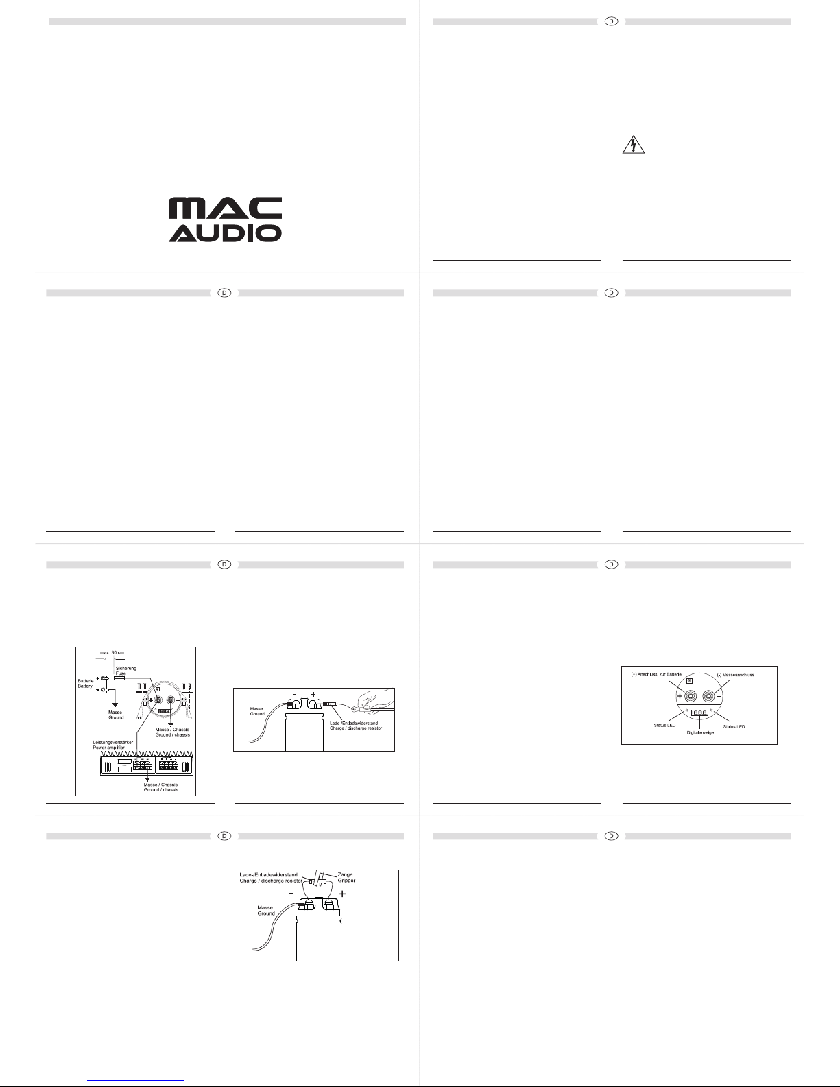
7. AUSBAU/ENTLADEVORGANG (BILD 4)
Vor dem Ausbau muss der Kondensator aus
Sicherheitsgründen entladen werden. Beim Ausbau
können bei einem Kurzschluss hohe Stromwerte
entstehen und Funken.
Der Kondensator kann dabei beschädigt werden oder
explodieren.
Entladen Sie den Kondensator daher niemals durch
Kurzschluss sondern nur mittels des mitgelieferten
Widerstandes!
Zum Entladen des Kondensators trennen Sie zunächst
das (+)-Anschlusskabel vom Kondensator. Der
Masseanschluss (-) bleibt angeschlossen. Verbinden
Sie nun mit dem mitgelieferten Widerstand Plusund Minuspol des Kondensators. Der Widerstand
kann dabei heiß werden (Verbrennungsgefahr). Die
Kondensator wird nun entladen, die Digitalanzeige
und Statusanzeige erlischt ab einer Spannung von 5
Volt. Auch danach ist der Kondensator noch nicht ganz
entladen. Bitte warten Sie daher noch einige Minuten
(ca. 2 - 3 Minuten) bis zur vollständigen Entladung.
Bild 4
6. EINSCHALTVORGANG UND DISPLAY-
FUNKTIONEN
1. Beim ersten Auade-Prozess schaltet sich das
Board mit der Steuerelektronik und der digitalen
Anzeige automatisch ein. Beim Auaden des
Kondensators und bei einer Spannung von 5-9V
blinken die blauen Status-LEDs und die rote
Digitalanzeige. Die rote Digitalanzeige zeigt dabei
den Wert 0.00 an.
Ab 9V wird von der roten LED-Anzeige der
Spannungswert angezeigt, dabei blinken die LEDAnzeige und die Status-LEDs.
2. Ist die Kondensator voll aufgeladen, leuchten die
Status-LEDs und die Digitalanzeige ständig, und die
Digitalanzeige zeigt die Versorgungsspannung der
Fahrzeugelektronik an (ab einem Wert von 10V).
3. Wenn die Gleichspannung der Fahrzeugelektronik
um mehr als +/-0.1 Volt schwankt, arbeitet das
Board mit der digitalen Anzeige und den blauen
LEDs automatisch, es bleibt eingeschaltet (Beispiel:
das Audio System gibt starke Bässe wieder oder es
wird ein anderes elektronisches Gerät verwendet,
welches Spannungseinbrüche verursacht).
4. Wenn die Gleichspannung des Fahrzeuges stabil
ist und nicht um +/-0.1 Volt schwankt, behält das
Board mit der Digitalanzeige und den Status-LEDs
zunächst den „EIN“-Status. Die Digital Anzeige und
die Status-LEDs schalten sich jedoch nach einer
Minute automatisch aus und bleiben im StandbyModus, um anzuzeigen, dass die Spannung im
Fahrzeug stabil ist.
5. Schwankt die Versorgungsspannung im Fahrzeug
wieder um +/-0.1 Volt, schaltet sich das Board mit
der Digitalanzeige und den Status-LEDs wieder ein.
Bild 3: Anschlüsse / Anzeigen
Sicherung in der Hauptstromleitung (+) zur Batterie
bendet. Diese Sicherung bendet sich in kurzem
Abstand zum Pluspol der Batterie (ca. 20 bis 30 cm).
Falls diese Sicherung nicht vorhanden ist, montieren Sie
diese Sicherung.
Bild 1: Anschlussschema
5. ERSTE INBETRIEBNAHME/AUFLADEN
Verwenden Sie beim ersten Auaden des Kondensators
unbedingt den mitgelieferten Widerstand! Dadurch
werden ein zu hoher Ladestrom und Anschlussfunken
vermieden.
Der Widerstand kann dabei heiß werden
(Verbrennungsgefahr). Ist der Kondensator auf 10V
aufgeladen, verbinden Sie das vorbereitete Pluskabel
mit dem Kondensator. Der Kondensator wird nun auf
die Batteriespannung (12 bis 14,8V) aufgeladen.
Bild 2: Auaden des Kondensators
3. BESCHREIBUNG
Dieser Hochleistungskondensator mit DigitalAnzeige ist ein Energiespeicher zur Stabilisierung
der Stromversorgung von Hochleistungsverstärkern.
Bei der Wiedergabe von Bassimpulsen benötigt der Verstärker hohe Stromwerte (Impulse). Da
Autobatterien nicht dafür ausgelegt sind, hohe
Stromwerte für Hochleistungs-Car-Audio-Systeme kurzzeitig abzugeben, ist der dieses Produkt die logische
Ergänzung Ihres Audio-Systems. Die Basswiedergabe
Ihres Audio-Systems wird durch dieses Gerät verbessert. Es ist in der Lage, große Energiemengen zu speichern und schnell wieder abzugeben.
Eine andere Eigenschaft des Kondensators mit Digital-
Anzeige ist es, die Wechselspannung zu ltern, die vom
Netzteil des Verstärkers induziert wird. Dieses kann
sonst Störgeräusche im Audio-System des Fahrzeuges
verursachen.
4. INSTALLATION
Montage des Kondensators
Für eine optimale Wiedergabe sollte der Kondensator
mit Digital-Anzeige so dicht wie möglich am Verstärker
installiert werden. Der ideale Einbauplatz beinhaltet
kurze Leitungswege und isoliert den Kondensator von
der vom Verstärker erzeugten Hitze.
Montieren Sie den Kondensator mit den beigelegten
Halteklammern aus transparentem Kunststo und
Schrauben fest im Fahrzeug.
Verlegen Sie die Kabel so, dass die Isolierung nicht
beschädigt werden kann.
Verbindung des Massekabels (-)
Das Massekabel (-) des Kondensators sollte so kurz
wie möglich sein und direkt mit dem Fahrzeug-Chassis
verbunden werden an einer abisolierten, sauberen
Metalloberäche. Vergewissern Sie sich, dass die
Verbindung sicher ist und nicht locker.
Verbinden Sie den Kondensator-Masseanschluss (-)
nicht mit dem Masseanschluss oder Massekabel des
Verstärkers (siehe Bild 1). Die Leitungen zum Plusund Minuspol des Kondensators müssen denselben
Querschnitt haben wie die Stromleitungen zum
Verstärker.
Vorbereitung der Verbindung des Pluskabels (+)
Das Kabel zum Pluspol der Kondensators sollte
so kurz wie möglich sein und mit dem Batterie(+)Anschluss des Verstärkers verbunden werden. Es
dürfen keine Sicherungen in das Kabel zwischen
Hochleistungsverstärker und Kondensator eingebaut
werden. Vergewissern Sie sich, dass sich eine passende
Elektrolyt auslaufen und das Fahrzeug verunreinigt
bzw. beschädigt werden. Das Elektrolyt ist
gesundheitsschädlich und darf daher nicht
verschluckt werden.
• Der Kondensator arbeitet nur dann einwandfrei,
wenn die Verkabelung richtig vorgenommen wird wie
in dieser Einbauanleitung beschrieben.
• Beziehen Sie sich immer auf die Bedienungsanleitung
zur korrekten Installation und Herstellen der
Verbindungen, und/oder zum Laden/Entladen des
Kondensators.
• Die Sicherheitsbestimmungen für tragende
Karosserieteile, die Vorschriften der inneren
Fahrzeugsicherheit STVZO-TÜV und die Vorschriften
des zuständigen Fahrzeugherstellers sind unbedingt
zu beachten.
• Betreiben Sie den Kondensator niemals mit einer
höheren Spannung wie in den technischen Daten
angegeben.
• Installieren Sie den Kondensator niemals so, dass er
direktem Sonnenlicht ausgesetzt ist oder hohen oder
extremen Temperaturen (der Einsatzbereich ist -20 –
+60°C). Achten Sie auf einen kühlen Einbauplatz.
• Sind äußere Verformungen des Aluminiumgehäuses
zu sehen, sind Schichten im Inneren beschädigt.
Der Kondensator darf dann nicht mehr verwendet
werden und muss entsorgt werden.
• Wasser, Öl und Fett sind vom Kondensator
fernzuhalten.
• Der Kondensator muss an einem sicheren, trockenen
Ort montiert werden.
• Bei der ersten Inbetriebnahme muss der beigepackte
Ladewiderstand verwendet werden zum Auaden
des Kondensators, da sonst durch den hohen
Einschaltstrom Funken entstehen und Anschlüsse
und Kabel beschädigt werden (s. Absätze 5 und 7).
• MAC AUDIO übernimmt keine Verantwortung
für irgendwelche Schäden (körperliche Schäden,
Gehörschäden, Sachschäden) die auftreten können
durch den Missbrauch dieses Produktes, d.h. für eine
falsche oder unsichere Montage oder einen falschen
Anschluss.
2. VERPACKUNGSINHALT
A. Hochleistungskondensator mit digitalem Display
B. Schutzabdeckung
C. Montageklammern
D. Bedienungsanleitung
E. Beutel mit Befestigungsschrauben,
Unterlegscheiben, Inbusschlüssel und Lade-/
Entladewiderstand 47 Ohm
CAP 1200F
BEDIENUNGSANLEITUNG/GARANTIEURKUNDE
OWNER’S MANUAL/WARRANTY DOCUMENT
Danke, dass Sie sich für ein Produkt von MACAUDIO
entschieden haben. Wir hoen, Ihnen die
Funktion dieses Qualitäts-Kondensators mit den
Beschreibungen in dieser Bedienungsanleitung
einfach und verständlich erklären zu können.
Bitte lesen Sie diese Anleitung sorgfältig vor der
Installation durch, um zu verhindern, dass Ihr AudioSystem oder die Fahrzeugelektronik beschädigt wird
oder Sie verletzt werden.
Diese Bedienungsanleitung enthält detailierte
Informationen über die Funktion, Installation und
Handhabung des Hochleistungskondensators.
ENTSORGUNGSHINWEISE
Gemäß der europäischen Richtlinie 2002/96/EC
müssen alle elektrischen und elektronischen Geräte
über lokale Sammelstellen getrennt entsorgt werden.
Bitte beachten Sie die lokalen Vorschriften und
entsorgen Sie Ihre Altgeräte nicht mit dem normalen
Hausmüll.
1. WICHTIGE SICHERHEITSHINWEISE
Der Hochleistungskondensator entspricht den
Vorschriften der KFZ-Richtlinie für den Betrieb in
Fahrzeugen innerhalb der Europäischen Union und
hat daher eine E-Typenzulassung.
Der Anschluss des Hochleistungskondensators an
das 12-V-KFZ-Bordnetz darf nur durch qualiziertes
Fachpersonal und mit besonderer Sorgfalt erfolgen.
Bei Kurzschluss des Kondensators und Kurzschlüssen
im Fahrzeug können gefährlich hohe Ströme ießen.
ACHTUNG:
Wenn Sie einen Warnton hören, klemmen
Sie SOFORT den Kondensator von der
Versorgungsspannung ab! Wird der
Kondensator länger als 10 Sekunden
verpolt betrieben, besteht Explosionsund Verletzungsgefahr !
• Auch die Fahrzeugelektronik und eingebaute
elektronische Geräte können bei falsch gepoltem
Anschluss beschädigt werden, ebenso kann
1
54
76
32
8. TECHNICAL DATA/SPECIAL FEATURES
Capacity: 1.2 Farad ±10 %
Maximum operating
voltage: 12-14.8 V DC
direct-current voltage
Operating temperature: -20 – +60 °Celsius
E.S.R.: < 0.004 Ohm @ 100Hz/25°C
Dimensions (Ø x H): 76 x 220 mm
Weight: 1.45 kg
• 3.5-character digital voltage display with red LEDs
• Two blue LEDs to display the operating voltage
• Warning (peep sound) in the event of incorrectly
connected poles and short circuit
• Aluminium cup made from brushed aluminium
• Sturdy nickel-plated hexagonal-socket screw
terminals in
a chrome look
• Protective cover made from transparent plastic
switch o automatically after one minute, however,
and remain in a standby mode to indicate that the
voltage in the vehicle is stable.
5. If the supply voltage in the vehicle uctuates by
+/-0.1 volts again, the board with the digital display
and status LEDs will switch back on.
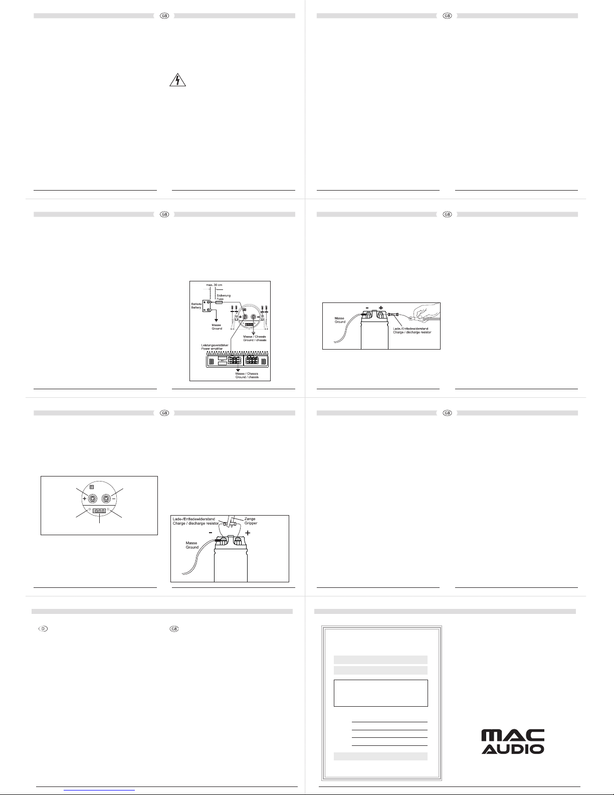
Fig. 3: Connections/Displays
Status LED Status LED
(-) Earth terminal(+) Battery terminal
Digital display
7. REMOVAL/DISCHARGE PROCESS (FIG. 4)
For your safety the capacitor must be discharged
before it is removed. If a short circuit is caused during
the removal process, high current values and sparks
can occur.
This can damage the capacitor or cause it to explode.
Never discharge the capacitor by shorting it! Only
use the supplied resistor!
To discharge the capacitor rst disconnect the (+)
connecting cable from the capacitor. The earth terminal
(-) should remain connected. Now connect the supplied
resistor to the positive and negative terminals of the
capacitor. The resistor can get hot during this process
(risk of burning). The capacitor is now discharged;
the digital display and status indicator go out when
5 volts is reached. Even now the capacitor is not fully
discharged. Please wait a while (approx. 2-3 minutes)
until it is completely discharged.
Fig. 4
5. INITIAL USE/CHARGING PROCEDURE
The supplied resistor must be used when charging
the capacitor for the rst time! This will prevent an
excessive charging current and connecting sparks from
occurring.
The resistor can get hot during this process (risk of
burning). When the capacitor is charged to 10V connect
the prepared positive cable to the capacitor. The
capacitor is now charged to the battery voltage (12 to
14.8V).
Fig. 2: CHARGING THE CAPACITOR
6. SWITCH-ON PROCEDURE AND DISPLAY
FUNCTIONS
1. When the initial charging process starts the control
electronics board and the digital display switch on
automatically. The blue status LEDs and the red
digital display ash when the capacitor is charging
and if the voltage level is between 5 and 9V. The red
digital display indicates the value 0.00 during this
process.
After reaching 9V the voltage value is indicated by
the red LED display, whereby the LED display and
status LEDs ash.
2. When the capacitor is fully charged, the status LEDs
and the digital display illuminate permanently. The
digital display will also indicate the supply voltage of
the vehicle‘s electronics (from 10V).
3. If the DC voltage of the vehicle‘s electronics
uctuates by more than +/-0.1 volts, the board
with the digital display and blue LEDs operates
automatically, and it remains switched on (example:
the audio system reproduces heavy bass lines or
another electronic device is being used that causes
voltage dips).
4. If the DC voltage of the vehicle is stable and does
not uctuate by +/-0.1 volts, the board with the
digital display and status LEDs initially retains its
„ON“ status. The digital display and status LEDs
4. INSTALLATION
Installing the capacitor
To ensure optimum reproduction the CAP 1200F should
be installed as close to the amplier as possible. Ideally,
the capacitor should be installed with short cables in an
area that is protected from the heat generated by the
amplier.
Install the CAP 1200F securely in the vehicle by using
the supplied transparent plastic brackets and screws.
Lay the cables in such a way that protects the insulation
from damage.
Connecting the earth cable (-)
The capacitor‘s earth cable (-) should be as short
as possible and connected directly to a bare, clean
metal surface on the vehicle‘s chassis. Make sure this
connection is secure and not loose in any way.
Do not connect the capacitor‘s earth terminal (-) to the
amplier‘s earth terminal or earth cable (see Fig. 1). The
lines connected to the capacitor‘s positive and negative
terminals must be of the same cross section as the
power lines used for the amplier.
Preparing the connection for the positive cable (+)
The cable used for the capacitor‘s positive terminal
should be as short as possible and connected to the
(+)battery terminal on the amplier. No fuses should
be installed in the cable between the high-performance
amplier and capacitor. Make sure there is a suitable
fuse in the main power line (+) to the battery. This fuse
is located a short distance from the battery‘s positive
terminal (approx. 20 to 30 cm). If this fuse is not
present, please ensure you install it.
Fig. 1: WIRING DIAGRAM
• The safety requirements for load-bearing body
parts, the regulations of the Road Trac Act and
the regulations of the corresponding vehicle
manufacturer must be observed without fail.
• Never operate the capacitor with a voltage higher
than that specied in the technical data.
• Never install the capacitor in such a way that it is
exposed to direct sunlight or extreme temperatures
(the operating range is -20 – +60°C). Make sure that
the space selected for installation is cool.
• If the exterior of the aluminium housing is visibly
deformed, it means interior layers are damaged. The
capacitor should then no longer be used and must be
disposed of.
• The capacitor must be protected from contact with
water, oil and grease.
• The capacitor must be mounted in a safe, dry place.
• The supplied charging resistor must be used when
charging the capacitor for the rst time, otherwise
sparks could be generated by the high inrush current
and damage connectors and cables (see sections 5
and 7).
• MAC AUDIO accepts no responsibility for any damage
caused (e.g. physical damage, hearing loss, damage
to property, etc.) as a result of misuse of this product,
i.e. due to incorrect or unsafe installation or incorrect
connection.
2. PACKAGE CONTENTS
A. High-performance capacitor with digital display
B. Protective cover
C. Mounting brackets
D. Operating instructions
E. Bag containing screws, washers, Allen key and
47ohm charging/discharging resistor
3. DESCRIPTION
This high-performance capacitor with digital display is
an energy storage module which stabilises the power
supply for high-performance ampliers. In order to
reproduce bass pulses the amplier needs high current
values (pulses). As car batteries are not designed to
deliver a high short-term current for high-performance
car audio systems, it makes the CAP 1200F a logical
addition to your audio system. The bass response
generated by your system will be enhanced as a result.
This capacitor is capable of storing a large amount of
energy and releasing it again quickly.
Another feature of the CAP 1200F is its ability to lter
AC voltage that is induced by the amplier‘s power
supply unit. If this is not ltered, it can cause static
noise in your vehicle‘s audio system.
Thank you for choosing a MAC AUDIO product. We
hope this manual clearly explains the functionality of
your high quality capacitor and that the descriptions
used are simple and easy to understand.
Please read this manual carefully prior to installation
to avoid damaging your audio system and the vehicle‘s
electronics, and to prevent personal injury.
This manual contains detailed information regarding
the functionality, installation and operation of your
high-performance capacitor.
INSTRUCTIONS FOR DISPOSAL
In accordance with European Directive 2002/96/EC all
electrical and electronic appliances must be disposed
of separately via local collection points. Please observe
the local regulations and do not dispose of your old
appliances with normal household waste.
1. IMPORTANT SAFETY PRECAUTIONS
This high-performance capacitor complies with the
requirements of the Automotive Directive for use in
vehicles within the European Union and therefore has
E-type approval.
The high-performance capacitor should only be
connected to the vehicle‘s 12 V electrical system
by qualied personnel with the utmost care. If the
capacitor short circuits or there are short circuits in the
vehicle, it can result in a dangerously high current being
generated.
CAUTION:
If you hear a warning tone, disconnect
the capacitor from the power supply
IMMEDIATELY! If the capacitor is operated
for longer than 10 seconds with reverse
polarity, there is a risk of explosion and
injury!
• The vehicle‘s electronic system and any integrated
electronic devices can be damaged as a result of
incorrect polarity. In addition, electrolyte can leak
and damage or contaminate your vehicle. Electrolyte
is harmful to your health and must not be swallowed.
• The capacitor will only operate correctly if it is
connected in accordance with these installation
instructions.
• Always refer to the manual for correct installation
and connection and/or for charging/discharging the
capacitor.
43
1 2
5 6
Wir gratulieren Ihnen! Durch Ihre kluge Wahl sind Sie Besitzer
eines MAC AUDIO-Produktes geworden. Wir gewähren Ihnen für dieses
Produkt 2 Jahre Gewährleistung.
Unsere Produkte werden während des gesamten Fertigungsvorganges laufend kontrolliert und geprüft. Im Servicefall beachten Sie bitte
folgendes:
1. Die Gewährleistungszeit beginnt mit dem Kauf des Produktes und gilt
nur für den Erstbesitzer.
2. Während der Gewährleistungszeit beseitigen wir etwaige Mängel, die
nachweislich auf Material- oder Fabrikationsfehler beruhen, nach unserer
Wahl durch Austausch oder Nachbesserung der defekten Teile. Weitergehende Ansprüche, insbesondere auf Minderung, Wandlung, Schadenersatz oder Folgeschäden sind ausgeschlossen.
3. Am Produkt dürfen keine unsachgemäßen Eingrie vorgenommen
worden sein.
4. Bei Inanspruchnahme der Gewährleistung wenden Sie sich bitte
zunächst an Ihren Fachhändler. Sollte es sich als notwendig erweisen,
das Produkt an uns einzuschicken, so sorgen Sie bitte dafür, dass •
das Produkt in einwandfreier Originalverpackung verschickt wird, • die
Kaufquittung beigefügt ist.
5. Von der Gewährleistung ausgenommen sind: • Leuchtmittel • Verschleißteile • Transportschäden, sichtbar oder unsichtbar (Reklamationen
für solche Schäden müssen umgehend bei der Transportrma, Bahn oder
Post eingereicht werden.) • Kratzer in Metallteilen, Frontabdeckungen
u.s.w. (Diese Defekte müssen innerhalb von 5 Tagen nach Kauf direkt bei
Ihrem Händler reklamiert werden.) • Fehler, die durch fehlerhafte Aufstellung, falschen Anschluss, unsachgemäße Bedienung (siehe Bedienungsanleitung), Beanspruchung oder äußere gewaltsame Einwirkung entstanden
sind. • Unsachgemäß reparierte oder geänderte Geräte, die von anderer
Seite als von uns geönet wurden.
• Folgeschäden an fremden Geräten • Kostenerstattung bei Schadensbehebung durch Dritte ohne unser vorheriges Einverständnis. • Batterien
und Akkus.
Congratulations! You have made a wise selection in becoming the
owner of a MAC AUDIO product. We grant a 2-years warranty for this
product.
The equipments are checked and tested continously during the entire
production process. In case you have problems with your Audiovox equipment, kindly observe the following:
1. The guarantee period commences with the purchase of the component
and is applicable only to the original owner.
2. During the guarantee period we will rectify any defects due to faulty
material or workmanship by replacing or repairing the defective part at
our discretion. Further claims, and in particular those for price reduction,
cancellation of sale, compensation for damages or subsequential damages, are excluded.
3. Unauthorized tampering with the equipment will invalidate this
guarantee.
4. Consult your authorized dealer rst, if guarantee service is needed.
Should it prove necessary to return the component to the factory, please
insure that • the component is packed in original factory packing in good
condition • your enclose your receipt as proof of purchase.
5. Excluded from the guarantee are: • Illuminates • Wear parts • Shipping
damages, either readily apparent or concealed (claims for such damages
must be lodged immediately with forwarding agent, the railway express
oce or post oce). • Scratches in cases, metal components, front
panels, etc. (You must notify your dealer directly of such defects within
three days of purchase.) • Defects caused by incorrect installation or connection, by operation errors (see operating instructions), by overloading
or by external force. • Equipments which have been repaired incorrectly
or modied or where the case has been opened by persons other than
us. • Consoquential damages to other equipments. • Reimbursement of
cools, without our prior consent, when repairing damages by third parties
• Batteries and battery packs.
GEWÄHRLEISTUNGSKARTE
WARRANTY CARD
Serien-Nr./Serial-No.
Name und Anschrift des Händlers/Stempel
Name and address of the dealer/stamp
Käufer/Customer
Nur gültig in Verbindung mit Ihrer Kaufquittung!
No warranty without receipt!
Kaufdatum/buying date/date d‘achat
Lise-Meitner-Str. 9 • D-50259 Pulheim • Germany
Tel. +49 (0) 2234 / 807 - 0
Fax +49 (0) 2234 / 807 - 399
Internet: http://www.mac-audio.de
You can nd this manual in additional languages at:
www.mac-audio.de.
 Loading...