

Page 1
U
s
-
L
M
B
T
n
t
u
p
a
n
x
p
x
c
m
m
SB 2.0
U
LT
LS
er
US
O
a
In
ual
Lynx St
sup
erf
dio Tech
www.lyn
ort@lyn
ce
ology, In
studio.co
studio.co
.
P
age 1 of 45
Page 2

1 Intr
o
o
m
r
a
t
o
n
u
u
c
.
v
r
gi
a
U
s
o
k
l
o
n
e
n
n
r
U
C
w
s
t
g
.
h
t
n
e
f
.
.
r
.
.
v
.
A
p
r
r
n
.
d
0
P
p
a
.
.
p
h
r
t
L
a
.
.
o
.
.
.
.
.
.
.
.
.
o
o
.
.
.
R
C
C
.
.
.
a
.
.
.
.
.
r
.
.
.
o
.
.
t
.
.
.
.
.
.
.
.
.
.
C
.
.
.
.
l
l
.
.
.
.
.
.
.
.
.
.
.
.
U
.
.
.
.
.
.
.
.
.
.
.
.
p
.
.
.
.
h
h
.
.
.
.
.
.
.
.
.
.
.
.
.
.
.
.
.
.
.
.
.
.
.
.
.
.
.
.
.
.
.
s
.
.
.
.
.
.
.
.
.
.
.
.
.
.
.
.
.
1.1
1.2
2 Bef
2.1
2.2
3 No
4 Wa
5 Inst
5.1
5.2
6 Get
6.1
6.2
7 Aur
7.1
7.2
7.3
8 Usi
8.1
8.2
8.3
8.4
8.5
9 Tro
10 S
10.1
10.2
10.3
10.4
10.5
11 Li
12 W
duction ....
Over
Featu
re you be
In the
Oper
enclature
ranty Regi
llation Pr
Cloc
Instal
ing Started
Wind
Maci
ra Remot
Starti
Starti
Gene
the LT-
8/16
Use
Choo
Appli
Upda
bleshootin
pport.........
Lynx
Telep
Regis
Retur
Locat
ense Agre
arranty In
..................
iew ............
es ..............
n ................
box ...........
tional requi
sed in this
tration ......
cedures .....
Settings an
ing the Dri
..................
ws Quick
tosh Quick
Control A
g the Auro
g the Auro
al Operatio
SB .............
hannel Mo
ith USB 1.
ing a USB
cation Setu
ing Firmw
.................
..................
Website Su
one Suppo
ering your
Policy .....
ing the Seri
ment .........
ormation...
User
Table
..................
..................
..................
..................
..................
ements ......
manual .....
..................
..................
d Connecti
er and Aur
..................
udio Test ..
Audio Test
plication
a Remote
a Remote
.................
..................
es .............
, USB 2.0
ort ............
..................
re ...............
..................
..................
port Resou
t ................
T-USB .....
..................
l Number
..................
..................
Manual
f Conten
..................
..................
..................
..................
..................
..................
..................
..................
..................
ns ..............
ra Remote
..................
..................
..................
eference ...
ontrol App
ontrol App
..................
..................
..................
nd USB 3.0
..................
..................
..................
..................
..................
ces ............
..................
..................
..................
f Your LT-
..................
..................
s
..................
..................
..................
..................
..................
..................
..................
..................
..................
..................
ontrol Ap
..................
..................
..................
..................
ication wit
ication wit
..................
..................
..................
systems ....
..................
..................
..................
..................
..................
..................
..................
..................
..................
SB ...........
..................
..................
..................
..................
..................
..................
..................
..................
..................
..................
..................
..................
lication .....
..................
..................
..................
..................
in Window
in OS X .....
..................
..................
..................
..................
..................
..................
..................
..................
..................
..................
..................
..................
..................
..................
..................
..................
.............3
.............3
.............4
.............5
.............5
.............5
.............7
.............7
.............8
...........11
...........12
...........16
...........16
...........19
...........22
...........22
...........22
...........22
...........31
...........31
...........31
...........31
...........33
...........39
...........40
...........43
...........43
...........43
...........43
...........44
...........44
...........44
...........45
P
age 2 of 45
Page 3

1 Introduction
Thank you for purchasing the LT-USB™! We are proud to provide you with a reliable,
professional-quality product for your digital audio requirements.
This manual covers operation, product characteristics, and information to help you get
started. Additional information is available via our website’s support resources. Please refer
to Section 10, Support, at the end of this manual for support contact information.
The LT-USB is an LSLOT expansion interface that is designed to allow the Aurora
professional audio AD/DA converters to be used with USB 2.0 equipped laptop and desktop
computers. The LT-USB can be used with Windows or Mac based systems, with a
convenient and easy-to-use software interface for setting parameters, managing volume
levels, viewing real-time meters, etc. Up to 16 channels of simultaneous I/O are possible with
an Aurora 16, and 8 channels with an Aurora 8.
From laptops, to the most powerful servers, USB ports are found on nearly every computer
system in production. For the first time ever, Aurora converters can be used with virtually
any computer.
1.1 Overview
The Aurora/LT-USB turns your computer into a powerful digital audio workstation,
providing up to 16 total channels of mastering quality analog inputs and outputs at sampling
rates up to 96 kHz, and up to 8 channels at 176.4 kHz or 192 kHz. The included remote
control application provides zero-latency monitoring, accurate metering, adapter
configuration and flexible routing capabilities. With support for WDM and ASIO on
Windows computers and Core Audio with OS X Macintosh computers, virtually all
professional audio applications can work with the LT-USB.
The LT-USB features a USB 2.0 Device port (Type B) which is typically connected to a
computer via a standard high-speed USB 2.0 cable (provided). Installation of the LT-USB
into an Aurora is straightforward, as is the driver installation routine (Please note that driver
installation is not required for OS X – native support is provided by the operating system).
The Aurora Remote Control application allows control and status of hardware parameters
such as Sample Rate, Clock Source, Trim levels, and routing. On Windows systems, an
independent LT-USB control applet provides access to other important parameters such as
buffer size, device settings and status.
The LT-USB was designed with adaptability in mind. The hardware can be field
programmed through simple firmware updates which can be downloaded from the Lynx
Studio Technology website. In this way, the product’s functionality and feature-set can be
easily upgraded by the end-user.
Page 3 of 45
Page 4

1.2 Features
¾ USB 2.0 Device port (Type B)
¾ USB Audio Class 2.0 compliant
¾ With an Aurora 16, provides 16 channels of I/O at sample rates up to 96 kHz and 8
channels at up to 176.4/192 kHz
¾ With an Aurora 8, provides 8 channels of I/O at all sample rates
¾ Supports routing of USB audio streams to Aurora’s AES/EBU outputs
¾ Works with almost any USB 2.0-equipped computer
¾ Supports ASIO and WDM for Windows and CoreAudio for Mac OS X
¾ Fully supports current operating systems, Windows 7 and OS X 10.6.4+, as well as
Windows XP and Vista
¾ All relevant settings, such as sample rate selection, sync source selection, channel
routing, latency, and buffer size are enabled, controlled and monitored from the host
computer
¾ Full WDM and Core Audio implementation allows multiple channel support of 5.1 and
7.1 surround playback formats
¾ Easily installed into Aurora
¾ Supports external clocking with Windows and OS X
¾ Field programmable
¾ Ideal for fixed location or mobile recording applications
Page 4 of 45
Page 5

2 Before you begin
We recommend that you read through the entire manual to acquire an overview of the
installation procedure and use of the LT-USB. This manual will presume a working
knowledge of the Aurora converter. For additional information, please refer to the Aurora
User Manual.
It is also highly recommended that you have a good working knowledge of Windows and/or
Macintosh operating system basics and an understanding of computer hardware basics. This
information is widely available on the web and from various computer hardware and
software manufacturers.
We also strongly recommend you familiarize yourself with the basics of digital audio and
computer recording, and particularly with the basic functionality of your chosen audio
software. A solid grasp of the operational fundamentals of your Digital Audio Workstation
software and its user interface will go a long way toward enhancing your experience with the
LT-USB.
2.1 In the box
The following items are included in your LT-USB carton:
¾ LT-USB card in an antistatic bag
¾ One 6’ long Type-A to Type-B shielded USB 2.0 cable
¾ Lynx Installation CD containing current drivers and this manual
¾ Warranty registration card
¾ Quick Start Guide
¾ ½” Standoff Post
If any items are missing or damaged, please contact your dealer or Lynx at
http://www.lynxstudio.com.
2.2 Operational requirements
There are three essential elements that must be met for compatibility with the LT-USB:
1. The host computer must have a compatible and functional USB 2.0 port.
2. The host computer must meet the system requirements necessary for correct functioning
of the LT-USB.
3. The Aurora must have firmware revision 24 or above.
It also is important to note that most professional audio applications place significant
demands on your computer’s resources, and it is therefore recommended that you meet or
exceed the recommended system requirements for your Digital Audio Workstation software,
which will likely be greater than those listed for the LT-USB. Please refer to your audio
software’s documentation for more information.
Page 5 of 45
Page 6

2.2.1 Windows
¾ Intel Core 2 @ 1.6 GHz, or AMD equivalent
¾ PC or laptop manufactured after January 2006
¾ 1GB RAM
¾ One functional USB 2.0 port
¾ Windows XP with SP3 (32-bit), Windows Vista with SP2 (32-bit or 64-bit) or Windows
7 (32-bit or 64-bit)
NOTE: The LT-USB is not supported under Windows 95, 98, ME or Windows 2000.
Windows installed via BootCamp is not officially supported.
2.2.2 Macintosh
¾ Any Intel Processor based Mac or MacBook computer running OS X 10.6.4 or higher
¾ 1GB RAM
¾ One functional USB 2.0 port
NOTE: The LT-USB is not supported under OS 9 or OS X 10.6.3 or below.
2.2.3 Insuring compatible firmware on the Aurora
The LT-USB requires your Aurora converter to have Firmware Version 24 or later. This
should be verified prior to installing and configuring the LT-USB card. To determine what
firmware revision your Aurora has installed, press the TRIM and POWER buttons at the
same time with the power to the Aurora off. If the LED flashes over the numbers 2 on the
input row & 4 on the output row or above (i.e. 2&5, 2&9, etc.) in the Aurora Meter Display,
then your unit is compatible with the LT-USB. If pressing Power and Trim does not cause
any LEDs to flash, causes a sequence lower than 24 to flash, or causes a single number to
flash, then your unit needs to be updated.
If your Aurora has firmware version 13 or above, it can be updated by an Apple Macintosh
running OS X or a Windows PC with a MIDI interface. The Aurora firmware updater
program and instructions for use are available for download from the Lynx website at
Support > Downloads. If your unit has rev 12 or earlier, please contact Lynx Technical
Support (U.S. or Canada) or your local distributor for firmware update options. Please note
that Auroras manufactured in 2006 or later should have firmware revision 13 or above.
Page 6 of 45
Page 7

3 Nomenclature Used in this manual
The following typographic conventions are used in this manual:
¾ ALL UPPER CASE TEXT refers to a specific parameter selection control (i.e. SYNC
SOURCE) or a cable connection.
¾ Text in quotation marks indicates a parameter selection value or menu option (i.e.
“EXT”).
Phrases, such as: Start > Programs > Lynx Studio Technology use the greater than symbol
(“>”) to indicate multiple menu options or mouse selections within a software control
context.
4 Warranty Registration
Lynx is committed to providing you with the best service possible. To help us serve you
better, please be sure to register your LT-USB using one of the following methods:
Fill out and mail the Warranty Registration Card included with your LT-USB.
Register on the web at: www.lynxstudio.com > Support> Register Your Product
Once you are registered you will automatically receive notifications of new products and
upgrades.
Page 7 of 45
Page 8
5 Ins
t
n
o
r
r
c
e
u
c
o
n
P
e
p
s
c
a
n
c
L
s
a
s
B
w
A
e
i
w
s f
2
h
m
o
S
h
p
e
f
t
e
L
O
p
t
y
e
r
c
h
n
i
o
d
a
h
t
a
h
o
t
3
p
o
allation
rocedure
Please i
1. Rem
large
cove
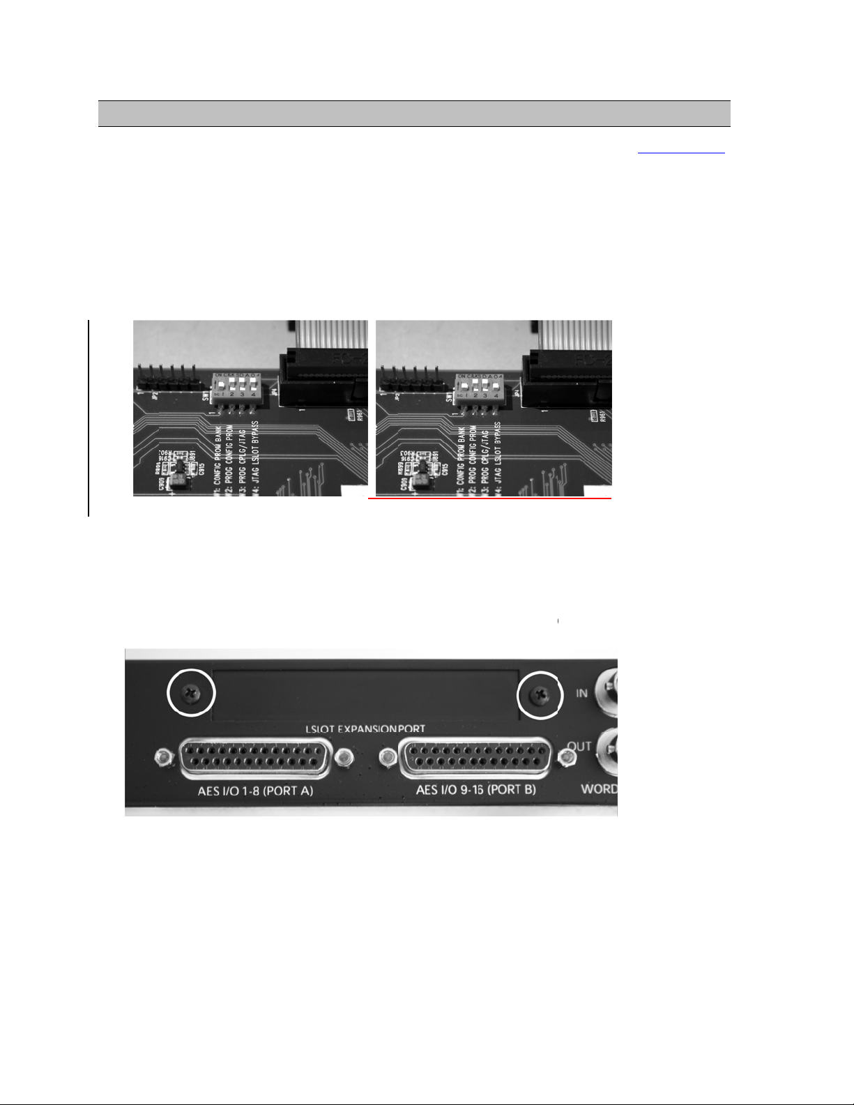
2. Befo
that
Slid
If yo
swit
sure that th
ve the AC
screws plu
on.
e installing
orrects the
switch 4 (l
are updati
hes, please
Aurora ha
ower cord
one small
the LT-US
urrent dra
beled W4 o
g an older
all Lynx T
irmware
nd take the
crew near t
card, you
for an Aur
n PCB) of
urora that
chnical Su
4 or above
top cover o
e center of
ust chang
ra with an
W1 to the
as jumper
port for ins
before proc
ff of the Au
he front fa
a dipswitc
T-USB
FF positio
ins at JP6,
ructions.
eeding. See
ora. There
eplate that
setting on
(towards b
nstead of t
Section 2.2.
re seven
olds the to
he Aurora
ck panel).
e W4
3. Rem
mou
after
ve the LS
ting screws
installation.
OT Expans
. Set these t
on Port cov
o screws a
r above the
side, as the
AES I/O P
will be use
rts by rem
d to secure
ving the tw
he LT-USB
P
age 8 of 45
Page 9
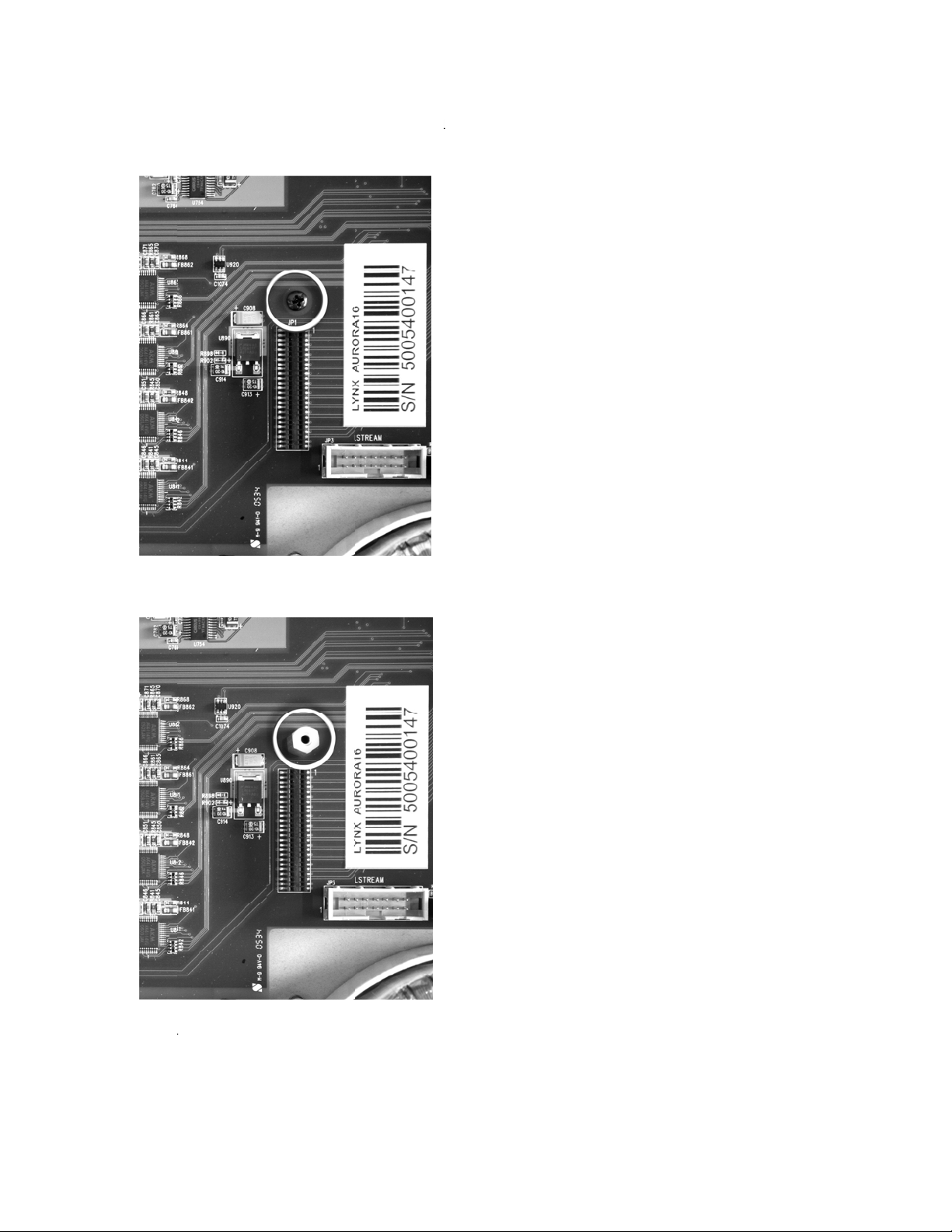
4. Rem
o
w
l
u
w
n
o
A
o
u
g
u
e
h
o
t
U
u
e
t
d
the
ve the scre
hite serial
from the
umber/barc
urora circ
de label. S
it board tha
t the screw
is adjacent
aside for re
to the JP1 c
se.
onnector an
5. Insta
6. Gro
bag.
l the stand
nding yours
ff post (incl
elf to earth
ded with t
round, rem
e LT-USB)
ve the LT-
in this sam
SB from i
hole.
s protective
anti-static
P
age 9 of 45
Page 10
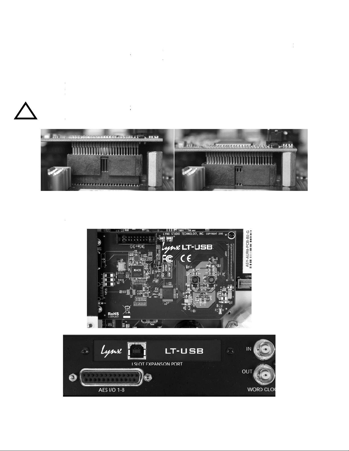
7. Atta
c
)
s
s
y
b
u
d
r
u
b
d
o
p
l
y
s
e
S
i
o
a
p
o
t
t
e
e
a
c
U
w
p
p
n
n
T
h
T
o
w
s
u
h
a
r
c
o
t
w
o
w
n
O
c
W
a
a
h
r
r
(JP1
to in
USB
pres
gentl
main
h the multi-
on the Aur
ure that the
connector
gently unti
flexed for
oard.
pin connect
ra mainbo
pins line u
ins appear t
the connec
the LSLOT
r on the ba
rd. The LT correctly
be lined u
or snaps int
connector
k edge of t
SB LSLO
ith the Aur
correctly
o place. In
ins to line
e LT-USB
connector
ra LSLOT
ith the Aur
ome cases,
p correctly
to the LSL
has a prote
onnector.
ora LSLOT
he board m
ith JP1 on
T connecto
tive sheath
hen the LT
connector,
y need to b
the Aurora
-
e
Use ca
could
8. Secu
of A
ut
tion to in
amage th
e the LT-U
rora. Keep
o not over t
ure that
unit.
B with thr
screws loos
ghten.
e pins li
e screws; o
until the L
e up as s
e on the st
-USB is p
own. Inc
ndoff and t
operly alig
rrect inst
o from the
ed, then tig
llation
back panel
ten snugly,
P
ge 10 of 45
Page 11

9. Reinstall the Aurora lid using the eight screws that had been removed in step 1. Do not
over tighten the small screw near the center of the front faceplate as it is easily damaged.
10. Plug in and power up the Aurora using the front panel standby switch. You can see the
LT-USB from the slits in the Aurora top cover. If the green LED on the LT-USB lights
up, the installation was successful. If the LED does not light, unplug the Aurora and remount the LT-USB, making sure that it is securely attached. Then plug in and power up
again. If the green LED still does not light, please contact Lynx Customer Support.
5.1 Clock Settings and Connections
Please see Section 2.6 Clock Settings and Connections, of the Aurora User Manual for
information about correct clocking of the Aurora within a digital audio system. When used
with an LT-USB, the SYNC SOURCE can only be from changed from the front panel of the
Aurora while the USB cable is disconnected. After the SYNC SOURCE is selected and
Synchrolock has achieved full lock, reconnect the USB cable. When the USB connection is
active, the Aurora will enter a lock-out mode, where some parameters such as SYNC
SOURCE/SAMPLE RATE cannot be altered from either the front panel or Remote Control
software.
5.1.1 Using the Internal Clock
We recommend using Internal as the SYNC SOURCE for the best clock performance.
In this state, the Aurora can respond to sample rate changes from audio software, but not all
applications will send these rate change requests.
In all compatible versions of Windows, ASIO applications will generally request sample rate
changes to follow the project sample rate, or the rate of the audio being played.
In Windows XP, applications using the WDM/DirectSound or MME/Wave Out driver
models will also typically request a sample rate change of the driver to match the project or
audio file rate.
In Windows Vista and Windows 7, WDM/DirectSound and WASAPI applications do NOT
typically request sample rate changes. Instead they rely upon Sample Rate conversion built
into the operating system to convert the play rate to the rate of the audio hardware. If one
wishes to avoid the effects of this rate conversion, the sample rate can be changed globally
from the Sound section of Windows control panel (Sound > Properties > Advanced). After
changing the sample rate, the play application often will need to be restarted.
In OS X, some Core Audio applications will initiate a change of sample rate to match the
project or audio file being played, and others will not. For the most part, professional audio
recording software does request sample rate changes, and consumer or media playback
software does not. Examples of the former would be Logic, ProTools, Cubase, Digital
Performer, etc. Examples of the latter would be iTunes, DVD playback software or
Quicktime.
Page 11 of 45
Page 12

When the application does not request a sample rate change, and one wishes to avoid sample
rate conversion, the sample rate can be changed from within Audio MIDI setup in OS X to
match the desired sample rate. After changing the sample rate, the play application of ten will
need to be restarted.
5.1.2 Using External / AES A / AES B Clock
The Aurora can slave to a master/house clock source via Word clock or via its AES inputs. In
this state, it is also important to verify that the clock source is operating at the same sample
rate as the audio being played, no matter what driver model is being used by the LT-USB.
See the Aurora manual for more information about these SYNC SOURCE choices.
If you wish to use the Lynx Synchrolock technology while clocking externally, it is crucial to
ensure Synchrolock has fully engaged before connecting the USB cable to the host computer.
Synchrolock engaging while the USB bus is active could cause loud, highly distorted signal.
5.1.3 Using LSLOT Clock
When an LT-USB equipped Aurora is used with a computer, it is possible to have the Aurora
slave to the clock generated by the USB interface. This would be the case when LSLOT is
selected as the SYNC SOURCE. As a general rule, we do not recommend this clocking
scheme. The clock signal derived from a USB device can be very inaccurate. Although
SynchroLock is capable of regenerating poor quality clock sources, there may be cases where
the USB-generated clock can fall outside of Synchrolock’s usable range, and the Aurora
sound quality will be adversely affected.
5.2 Installing the Driver and Aurora Remote Control Application
The Lynx Installation CD contains all driver files and utilities mentioned in the subsequent
installation steps, as well as the LT-USB manual, driver release notes and test files. If you do
not have a CD-ROM drive or need a more recent version, these files are available on our
website at http://www.lynxstudio.com/ > Support
If you have downloaded more recent drivers than those included on your Lynx Installation
CD, the following instructions can still be followed. Launch the driver install file from the
download rather than from the CD. If a previous driver version is present, it will
automatically be removed as part of the driver installation process. Note: no driver
installation is required for OS X, only for Windows.
Page 12 of 45
Page 13
5.2.1
W
eANA
L
t
t
n
k
P
r
b
v
n
o
-
e
L
b
C
B
d
m
a
i
e
p
r
t
n
d
e
u
r
b
e
A
h
x
t
l
e
I
e
indows X
, Vista (32
bit or 64-b
t), or Win
ows 7 (32-
it or 64-bi
)
1. Pow
2. The
Inser
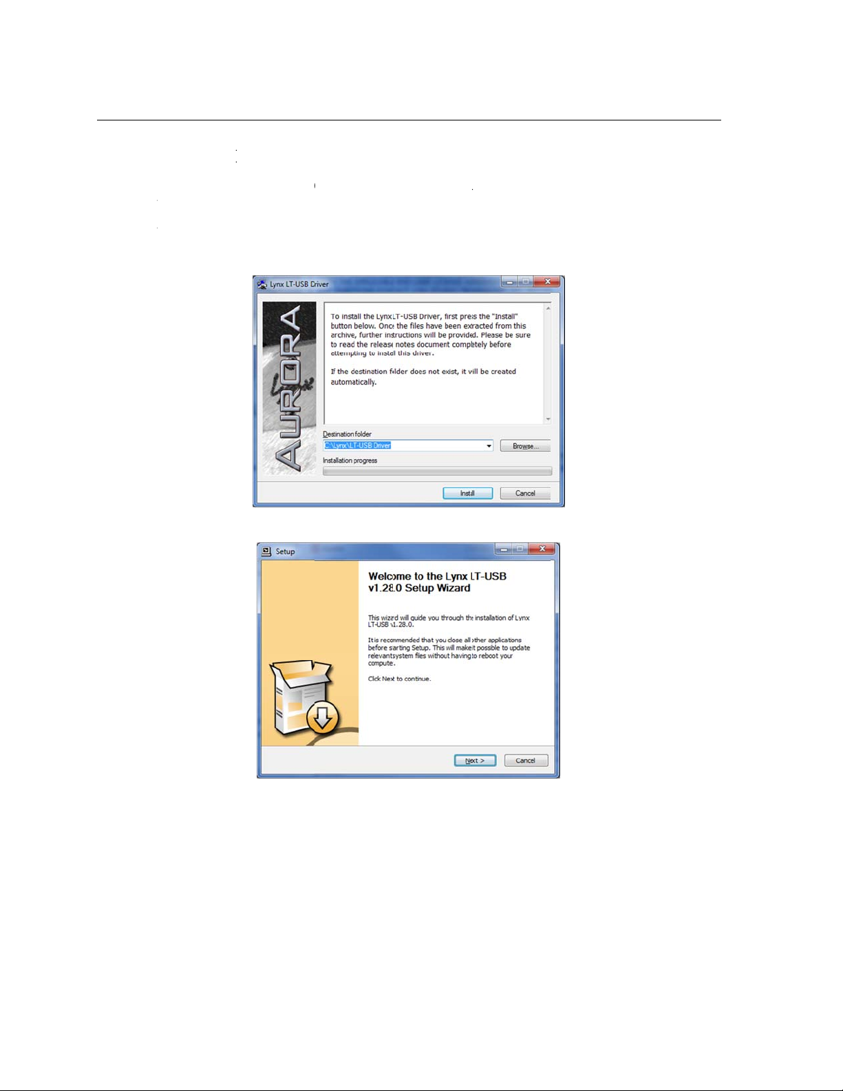
3. Loca
4. Whe
5. Clic
r on the Au
LOG OUT
T-USB dri
the Lynx I
e the Wind
prompted,
“Next >” o
ora with th
utton to “
er should
stallation
ws\LT-US
accept the
n the welco
USB cabl
SLOT IN”.
e installed
D into you
folder on
efault desti
e screen
disconnect
rior to conn
computer’s
he CD. Do
ation folde
. From th
ecting the
disk drive.
ble-click t
of C:\Lyn
front pane
urora to the
e LTUSBS
and click “
, set the TO
computer.
tup.exe fil
nstall”.
.
P
ge 13 of 45
Page 14
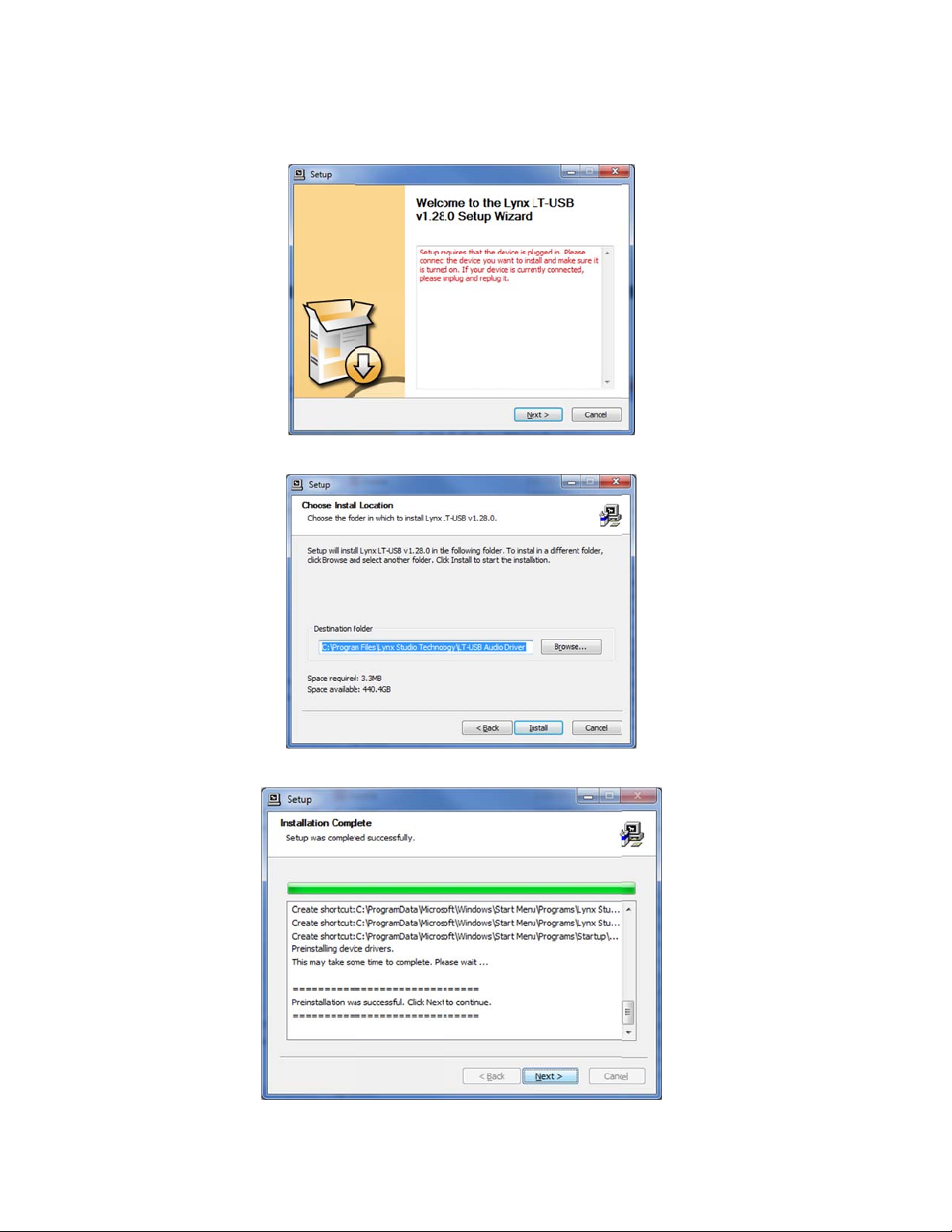
6. The
s
e
r
s
N
n
h
n
a
a
t
N
b
l
k
n
USB
ystem will
and click “
earch for t
ext>”
e LT-USB
nd should
e unable to
find it. Con
ect the LT-
6. Acc
7. Afte
pt the defau
installatio
t destinatio
has comple
folder for
ted, click “
he driver fi
ext >”
es and clic
“Install>”
P
ge 14 of 45
Page 15

8. Clic
k
m
f
o
c
n
O
L
N
o
p
n
u
.
e
r
s
s
a
P
a
e
a
o
h
r
c
e
t
i
w
n
t
h
o
n
h
a
c
e
a
p
a
e
c
e
m
y
n
o
c
u
e
h
m
p
t
R
e
e
l
l
d
y
r
u
r
w
L
A
c
c
l
o
c
m
y
e
r
u
p
h
b
M
a
g
e
l
n
u
h
’
A
n
n
l
e
n
n
“Finish >”
9. You
is sa
10. On s
this
until
11. Whe
from
Secti
5.2.2
1. The
up.
disc
2. Sim
port.
appli
3. To i
CD.
7, A
ay receiv
e to disrega
me system
ase, run the
it complete
the install
Start > All
on 7, Auror
S X
T-USB us
o addition
nnected. Fr
ly connect t
The Aurora
cations.
stall the Au
Double-cli
rora Remot
a warning
d this warn
the Windo
wizard usi
. Skipping
tion is finis
rograms >
Remote C
s the built-i
l driver inst
m the front
e appropri
driver devi
ora Remot
k the Auror
Control A
hat the driv
ng and sele
s hardwar
g the “Auto
his step ma
ed, you ca
Lynx Studi
ntrol Appli
USB 2.0 a
allation is r
panel, set t
te USB cab
es will im
Control ap
RemoteIns
plication
r has not b
t “Continu
wizard wil
atic Instal
cause the
launch the
Technolog
ation Refe
dio class d
quired. Po
e TO ANA
le from the
ediately be
lication, lo
aller.pkg fi
eference.
en digitally
Anyway.”
launch pos
ation” opti
river to fun
Aurora Re
. For mor
ence.
iver provid
er on the A
OG OUT
urora to t
ome availa
ate the OS
e. For more
signed by
t driver inst
n, acceptin
tion incorr
ote Contro
informatio
ed in OS X
rora with t
arameters t
e computer
le to Core
X/LT-USB
informatio
icrosoft. It
llation. In
the default
ctly.
applicatio
, see
10.6.4 and
e USB cab
o “LSLOT”
s USB 2.0
udio
folder on th
, see Sectio
s,
e
.
P
ge 15 of 45
Page 16

6 Ge
t
u
r
i
a
L
g
n
n
u
p
A
h
h
h
L
n
n
d
e
t
i
y
e
k
t
r
o
t
o
a
e
l
o
m
s
s
w
r
f
O
D
y
v
m
c
s
u
h
s
B
i
t
v
g
e
t
A
a
n
a
o
h
w
s
a
n
e
a
t
hird
u
a
e
c
r
n
C
e
t
e
o
h
n
m
t
s
e
s
p
a
A
s
p
o
k
8
t
c
U
r
o
v
e
p
n
e
A
h
m
D
c
m
d
d
r
c
m
h
e
o
n
k
A
g
n
l
q
e
r
v
r
m
e
O
S
p
U
o
l
e
n
n
y
o
D
g
ting Star
ed
With the
now be
to verify
procedu
6.1 W
The inst
and the
verifyin
equipme
1. Con
an a
equi
that
are t
2. For t
state
from
3. On t
“LS
LT-USB d
sed with m
that the ins
e.
ndows Qui
llation of y
ynx Demo
that the int
t.
ect the Ana
dio signal f
ment, you
nalog Out
e outputs u
is test we
of the Auro
the Aurora
e Digital I/
OT IN”.
ivers and A
st popular t
allation wa
k Audio T
ur LT-US
pplication
rface is ins
og Outputs
r listening
ay be usin
1 & 2 of th
ed for this
ill set the
a. If this ha
ront panel
and Setti
rora Remo
-party a
successful
est
can be test
ncluded on
alled corre
of the Auro
ia headpho
the Lynx
Aurora ar
est.
urora on In
been alter
nd then rec
gs page of t
e Control a
dio applic
nd test the
d using the
the Lynx In
tly and pro
a to monit
es or spea
BL-AOUT
connected
ernal as the
d, disconne
nnect the
e ARC, ve
plication i
tions. How
urora wit
Aurora Re
tallation C
erly conne
ring equip
ers. Depen
5 or a thir
o your exte
clock sourc
ct the USB
SB cable.
ify that TO
stalled, the
ver, it is a
the followi
ote Contro
. This is a
ted to your
ent capable
ing on you
party equi
nal equip
e. This is th
able and se
ANALOG
urora can
ood practic
g
applicatio
uick way o
xternal
of deliveri
external
alent. Verif
ent. These
default
lect INT
UT is set t
f
g
4. Ope
Tech
and
corn
5. Loca
the f
6. In L
“Sin
the Lynx
ology > L
ouble-click
of your sc
e “SineWa
le to the co
nx Demo,
WaveMinu
emo applic
nx Demo,
to run it. T
reen. Make
eMinus16.
puter’s de
lick “File”
16.wav” a
tion by clic
r locate Wi
e Lynx De
certain that
av” in the
ktop.
nd navigate
d click “Op
king Start >
dows/Dem
o program
he Play De
upport fold
to the com
n.”
All Progra
32.exe on t
should app
ice is set t
er of the Ly
uter’s Des
s > Lynx
he Lynx Ins
ar in the up
Lynx LT-
x Installati
top, then se
tudio
tallation C
er left
SB/Aurora
n CD. Dra
ect
7. Clic
“Play.” Yo
u should se
the progre
s bar move
P
ge 16 of 45
from left to
right.
Page 17

n
r
s
1
r
r
d
p
C
u
e
a
i
I
e
y
k
s
o
d
g
h
r
h
o
8. Lau
mete
your
ch the Auro
activity fo
destination
a Remote
Analog O
evice, you
ontrol appl
tputs 1&2.
should be h
cation. Clic
f you have
aring audi
k the Analo
peakers or
as well.
I/O tab. C
eadphones
eck for
connected t
If the te
Section
t did not o
0,
erate as d
scribed or
ou receive
P
ge 17 of 45
d any erro
s, please re
fer to
Page 18

Troubleshooting.
Page 18 of 45
Page 19

6.2 M
a
a
T
n
e
u
v
i
c
d
t
i
n
u
p
A
h
u
o
w
D
“
d
e
v
m
l
o
m
s
s
T
B
n
m
w
m
w
G
a
s
v
g
t
a
e
h
c
o
p
n
s
r
n
C
s
e
n
d
o
k
8
e
m
w
n
h
c
y
m
d
d
x
l
y
n
o
-
h
i
r
v
p
n
e
o
a
n
y
cintosh Q
ick Audio
est
The inst
and the i
interface
1. Ope
2. If th
Men
3. All a
this l
llation of y
unes soft
is installed
Audio MI
Audio Dev
” from the
ailable au
st.
ur LT-US
are that is i
correctly an
I Setup fro
ices windo
Window”
io devices
can be test
cluded wit
d properly
Applicati
does not a
enu.
ill appear i
d using the
OS X. Thi
onnected to
ns > Utiliti
pear autom
the left pa
Aurora Re
is a quick
your extern
s.
atically, the
e. Locate t
ote Contro
ay of verif
al equipme
select “Sh
e Lynx LT
applicatio
ing that th
t.
w Audio
USB from
4. Sele
5. Loca
6. Con
soun
the f
an a
equi
that
are t
t this devic
output”
e “SineWa
le to the co
ect the Ana
dio signal f
ment, you
nalog Out
e outputs u
. From the
eMinus16.
puter’s de
og Outputs
r listening
ay be usin
1 & 2 from
ed for this
ear icon in
if” in the “
ktop.
of the Auro
ia headpho
the Lynx
the Aurora
est.
the bottom
upport” fol
a to monit
es or spea
BL-AOUT
are connect
P
ge 19 of 45
left corner,
er of the L
ring equip
ers. Depen
5 or a thir
d to your e
lick “Use t
nx Installat
ent capable
ing on you
party equi
ternal equi
is device f
on CD. Dr
of deliveri
external
alent. Verif
ment. Thes
r
g
g
e
Page 20

7. For t
h
e
n
e
r
n
t
t
s
1
w
e
r
s
e
m
A
n
i
p
A
n
r
o
o
t
u
e
a
e
s
e
r
d
c
a
o
n
y
c
e
e
X
y
C
a
w
d
e
a
s
a
n
d
y
r
e
N
t
b
n
t
e
n
of th
Auro
is test we
Aurora. If
ra front pan
ill set the
this has bee
l and then
urora to Int
altered, di
econnect th
rnal as the
connect th
USB cabl
clock sourc
USB cable
.
. This is th
and select I
default sta
T from th
e
8. Lau
“Sin
9. High
prog
10. Ope
meter ac
your des
ch iTunes f
WaveMinu
ight this fil
ess bar is
the Lynx
ivity for A
ination dev
om “Applic
16.aif” file
from the s
oving from
urora Rem
alog Outpu
ce, you sho
ations” or f
from your
nglist and
left to right.
te Control
s 1&2. If y
ld be heari
om the OS
esktop into
lick the Pla
pplication.
u have spe
g audio as
dock. Dr
the iTunes
button. M
lick the A
kers or hea
ell.
g the
onglist
ke sure tha
alog I/O ta
phones con
the iTunes
. Check for
ected to
If the te
Section
t did not o
0,
erate as d
scribed or
ou receive
P
ge 20 of 45
d an
erro
s, please re
fer to
Page 21

Troubleshooting.
Page 21 of 45
Page 22

7 Aurora Remote Control Application Reference
The Aurora Remote Control (ARC) application allows control of Aurora parameters from a
convenient software interface. It also provides accurate real-time metering for all inputs and
outputs, and displays status information such as channel mode, sync source and sample rate.
The ARC is automatically installed with the Windows driver setup program, and is a separate
install under OS X (see Section 5.2, Installing the Driver and Aurora Remote Control
Application).
7.1 Starting the Aurora Remote Control Application within Windows
Make sure that the Aurora is powered up, and that the Aurora is connected to the computer
by a USB cable. From the Start Menu, click Start > Programs > Lynx Studio Technology >
Aurora Remote Control.
7.2 Starting the Aurora Remote Control Application within OS X
Make sure that the Aurora is powered up, and that the Aurora is connected to the computer
by a USB cable. From Finder, click Applications >Aurora.
7.3 General Operation
The Aurora Remote Control Application allows the user to control output levels, route inputs
to outputs, alter various parameters, and view accurate meters for inputs and outputs on a
connected Aurora. Most parameter changes will be reflected both on the Aurora front panel
and within the software application.
Some parameters can be established identically from the software or front panel. Other
parameters have extended functionality through the software, particularly routing functions
and setting trim levels. When these functions are modified in the software, the Aurora front
panel will indicate this by illuminating all the LEDs for that function. For instance, the front
panel choices for the button labeled TO ANALOG OUT and TO DIGITAL OUT are
“ANALOG IN”, “AES IN” and “LSLOT IN”. When selecting a choice from the front panel,
the LED will be illuminated for the active selection. If custom routing is established in the
software, all three LEDs will illuminate.
Page 22 of 45
Page 23

When th
e
r
d
a
e
o
C
c
S
A
o
r
D
o
m
e
r
t
C
r
b
n
E
n
b
n
e
l
,
u
k
U
b
n
L
h
e
T
b
n
r
s
c
u
n
o
e
r
u
e
n
o
e
e
e
r
m
s
e
L
e
w
e
r
o
h
m
o
a
n
o
n
i
n
y
g
f
,
N
e
e
t
r
a
i
t
h
e
e
o
t
n
h
y
y b
m
n
E
a
e
d
e
n
e
t
l
o
a
m
f
B
e
h
o
r
t
s
v
m
h
R
a
t
m
o
n
a
e
c
a
h
y
U
T
h
B
A
r
t
w
a
s
will ente
restricte
table det
q
SAM
This
corr
and/
w
SYN
This
prior
If no
sour
Aurora Re
a “lock-ou
to the AR
ils which f
PLE RATE
utton will
sponding L
r an operati
SOURCE
utton will
to the conn
clock signa
e will flash
mote Contr
” mode wh
software o
ont panel f
ot be activ
D. Sample
g system s
ot be activ
ction of th
is availabl
and the Au
l applicatio
re some fr
from setti
nctions are
. The curre
rate can onl
und settin
. The LED
USB cable
for the SY
ora will op
is run via
nt panel co
gs within t
mpacted b
t operating
e set fro
s page.
or the sync
will illumi
C SOURC
rate from it
he LT-US
trols will b
e operating
“lock out”
sample rate
within the
source, whi
ate.
selected, t
s internal cl
connectio
disabled,
system. Th
mode:
will be indi
host audio
ch has been
e LED for t
ck.
, the Auror
nd control i
following
ated by the
pplication
selected
e selected
e
r
t
y
u
Sync
This
LED will f
The
TO
NALOG O
This
Rem
appli
cation. LS
Auro
ra’s Analog
appli
cation, all t
cont
olled remot
TO
IGITAL OU
This
with
LSLOT sou
m routing i
cust
illu
inated, indi
IR/M
DI
This
LED will f
Peak
Meters
Thes
roLock
ynchroLoc
utton will
te Routing
utton will
LEDs will
nction nor
status mu
T
ot be activ
mode with
OT IN rout
outputs. If
ree LEDs
ly.
ot be activ
ces assigne
initiated fr
ating that t
nction nor
function n
ally. See th
t be establis
. For opera
SLOT sou
s play stre
any custom
ill be illum
. For opera
d should be
m within t
is paramet
ally. See th
rmally. See
Aurora m
hed prior to
ion with th
ces assigne
ms from th
routing is i
nated, indic
ion with th
selected wi
e ARC app
r is being c
Aurora m
the Aurora
nual a desc
the connec
LT-USB, e
should be
computer,
itiated fro
ating that t
LT-USB,
h the ARC
ication, all
ntrolled re
nual for inf
anual for i
iption of S
ion of the
ither LSLO
elected wit
ia the US
within the
is paramete
emote Rou
pplication.
hree LEDs
otely.
rmation.
nformation.
nchroLock.
SB cable.
IN or
the ARC
port, to the
RC
is being
ing mode
If any
ill be
i
IR T
This
ansceiver
will functio
normally.
See the Aur
ra manual
P
ge 23 of 45
or informat
ion.
Page 24

o METER
This button will function normally. See the Aurora manual for information.
a TRIM/AES MODE
When the METER select switch is set to “Analog”, this button normally allows the
nominal trim level to be set for the analog inputs and outputs. In “Lock Out” mode, this
button will not be active, and trims can be set for the Analog inputs and outputs from
within the Aurora Remote Control application. If the trim value for any analog I/O is
altered from within the software, both the +4 dBu and –10 dBV LEDs will be
illuminated, indicating that this parameter is being controlled remotely.
When the METER select is set to “Digital”, this control allows configuration of the
AES/EBU digital I/O. In “Lock Out” mode, the button will not be active, but the LEDs
will reflect the dual-wire state for the digital inputs and outputs.
s POWER
This button will function normally. See the Aurora manual for information.
Page 24 of 45
Page 25

7.3.1
A
e
C
T
T
A
T
r
T
R
o(S
O
Oal
l
TwD
P
e
l
t
h
e
t
s
u
l
t
a
a
o
D
s
R
L
g
m
A
a
u
A
r
e
u
e
a
O
v
t
s
a
o
n
s
s
u
t
u
o
u
b
o
t
t
n
d
e
t
a
e
r
+
e
e
R
e
w
e
m
n
o
l
h
s
a
m
e
e
d
e
u
v
o
r
d
i
y
e
a
t
-
u
.
w
p
o
A
n
n
A
c
p
v
t
c
nalog I/O
age
This pag
Remote
q
is viewabl
ontrol app
hese indica
d
etected on t
o
ccurs on th
2
50ms.
by clickin
ication.
ors will illu
e Aurora
Aurora An
the “Anal
inate whe
nalog Input
log Output
g I/O” Tab
three cons
and Outpu
. The indic
in the top le
cutive full-
s or when
tor will re
ft corner of
scale sampl
summing o
ain illumin
the Aurora
s are
verrun
ted for
w
e
r
t
g
r
1
i
hese meters
nalog Inpu
hese button
oups of fo
hese tabs al
emote Rou
utes to An
ource A an
6 additional
utput 1-4 t
UT switch
l three LE
luminated.
hese button
hen using
igital or LS
display the
s and Outp
allow the
rs channels
ow monito
ing is utiliz
log Out) or
d Source B)
monitor so
bs. For thes
n the Digit
s for the T
allow indi
emote Rou
OT input
instantaneo
ts.
nalog inpu
to be toggle
source gro
d. The Aur
Remote Ro
can be esta
rces (Sourc
custom m
l I/O & Set
ANALOG
idual moni
ing. Clicki
ource. Hol
s peak lev
or output t
d between
ps to be sel
ra can be s
ting. With
lished for
es C – R),
nitor sourc
ings page
OUT butto
or sources t
g a button a
ing down t
P
ge 25 of 45
l of audio b
ims to be s
4dBu (the
ected for th
t for global
emote Ro
ach output.
hich can be
s to be acti
ust be set t
on the Au
o be selecte
llows select
e CTRL ke
ing sent to
t. Each but
efault) and
Analog O
routing (i.e
ting up to t
Analog Out
accessed fr
e, the TO
“Remote”.
ora front pa
for each a
on of any
while sele
the Aurora
on allows
10dBV.
tputs when
AES In
o sources
uts 1-4 ha
m the
NALOG
In this stat
nel will be
alog outpu
nalog,
ting a sour
e
e
e
Page 26

c
ath
P
t
T
Rre
w
w
T
T
TAWchfo
W
t
eth
m
a
h
i
t
d
g
n
r
n
r
g
b
E
e
a
h
c
n
n
A
L
o
T
h
y
w
a
n
m
r
c
D
g
w
s
b
a
s
t
t
o
e
n
.
dj
t
n
u
o
f
L
s
C
b
C
a
n
O
o
c
u
o
n
o
e
u
R
h
h
o
h
i
p
o
o
i
m
I
r
o
n
m
v
e
o
a
u
i
a
S
o
w
i
n
t
g
o
”
e
p
t
d
s
d
g
uses the re
e monitor s
1
-16 will be
aining cha
ource for A
ssigned to
nels to be
alog Out 1
nalog Out
et sequenti
while holdi
1-16).
lly (i.e. if y
g down the
u select L
CTRL key,
LOT In 1 a
LSLOT In
y
u
i
Settings
lease note t
s
reams com
hese faders
emote Rou
commende
here the hi
hile adjusti
his display
his button e
his display
urora.
at with an
ng from the
allow contr
ing mode.
to leave t
hest fidelit
g a fader,
eveals the
ables the
eveals the t
-USB ins
host compu
l over the
his level att
ese faders i
is required
ill cause a
mount of at
ute functio
im, power
alled, LSL
er.
utput level
nuation oc
their defa
Holding d
ustment of
enuation, i
for the ass
p, and curr
T sources c
f each mon
urs in the d
lt, maximu
wn the SH
channel pai
dB, of a m
ciated mo
nt channel
rrespond t
itor source
igital doma
position i
FT key on
s.
nitor sourc
itor source.
ode settin
audio
hen in
n, so it is
situations
he keyboar
e.
of the
hen TRIM
annel per
llow the va
p
anel TRIM
hen POW
s
andby mod
s
t to “On”,
e Aurora, t
d
own the bla
ORIGIN is
roup basis
ue displaye
utton.
R UP MO
by pressin
pplying po
ereby bypa
k standby
set to “Rem
ontrollable
d in LOCA
E is set to “
the black
er to the A
sing stand
utton as A
te”, the A
rom the A
TRIM, w
Standby”, t
tandby butt
input of t
y mode. Th
power is a
rora trim le
C. When s
ich is contr
e Aurora c
n on the A
e Aurora w
s control c
plied.
els are set
t to “Local
llable from
n only com
rora front
ill immedia
n be toggle
n a 4-
, the trims
the front
out of
anel. When
ely power o
by holdin
n
P
ge 26 of 45
Page 27

Digital I
e
T
n
T
D
T
Rro(S
cto
A
TwD
ath
P
t
n
e
C
t
h
a
s
l
t
a
O
p
s
R
L
m
s
h
i
g
i
m
D
t
t
r
e
e
e
v
t
s
n
i
g
L
a
a
n
s
t
n
u
u
o
u
b
h
E
d
t
n
d
s
w
1
t
t
t
e
t
l
e
e
e
R
e
g
o
l
h
a
n
O
u
n
s
m
e
e
u
A
d
i
y
o
o
d
ft
e
v
t
.
w
o
e
t
i
A
c
S
o
a
r
t
t
c
s
1
o
d
/O & Setti
s Page
This pag
the Auro
o
is viewabl
ra Remote
hese indica
d
etected on t
o
the Auror
by clickin
ontrol appl
ors will illu
e Aurora
Digital Ou
the “Digit
cation.
inate whe
igital Input
puts. The i
l I/O & Set
three cons
and Outpu
dicator wil
ings” Tab i
cutive fulls or when a
remain illu
the top le
scale sampl
summing o
inated for
corner of
s are
errun occu
250ms.
s
a
s
d
hese meters
igital Input
hese tabs al
emote Rou
utes to An
ource A an
a
tive, the T
“Remote”.
urora front
hese button
hen using
igital or LS
c
uses the re
e monitor s
1
6 will be as
lease note t
s
reams com
display the
and Outpu
ow monito
ing is utiliz
log Out) or
d Source B)
DIGITAL
In this stat
anel will b
allow indi
emote Rou
OT input
aining cha
ource for D
igned to Di
at with an
ng from the
instantaneo
s.
source gro
d. The Aur
Remote Ro
can be esta
OUT switc
all three L
illuminate
idual moni
ing. Clicki
ource. Hol
nels to be
gital Out 1
ital Out 1-
-USB ins
host compu
s peak lev
ps to be sel
ra can be s
ting. With
lished for
on the Di
Ds for the
.
or sources t
g a button a
ing down t
et sequenti
hile holdi
6).
alled, LSL
er. By defa
l of audio b
ected for th
t for global
emote Ro
ach output.
ital I/O & S
TO DIGIT
o be selecte
llows select
e CTRL ke
lly (i.e. if y
g down the
T sources c
lt these au
ing sent to
Digital Ou
routing (i.e
ting up to t
For these s
ettings pag
L OUT but
for each d
on of any
while sele
u select L
CTRL key,
rrespond t
io streams
the Aurora
puts when
AES In
o sources
urces to be
must be se
on on the
gital output
nalog,
ting a sour
LOT In 1 a
LSLOT In
USB audi
re delivere
e
-
P
ge 27 of 45
Page 28

to the Analog Outputs. By manually assigning LSLOT sources to the Digital Outputs,
these signals can be mirrored to the Aurora AES/EBU outputs as well.
For example, to send USB audio streams to the digital outputs, assign LSLOT 1-16
(for an Aurora 8, assign LSLOT 1-8) to the digital outputs as “SOURCE A” and set
“TO DIGITAL OUT” to “REMOTE”.
f These faders allow control over the output level of each monitor source when in
Remote Routing mode. This level attenuation occurs in the digital domain, so it is
recommended to leave these faders in their default, maximum position in situations
where the highest fidelity is required. Holding down the SHIFT key on the keyboard
while adjusting a fader, will allow adjustment of channel pairs.
g This display reveals the amount of attenuation, in dB, of a monitor source.
h This button enables the mute function for the associated monitor source.
j This display indicates the status of the digital inputs. If a valid digital signal is present
the display will indicate “Locked”. If a valid digital signal is not present the display
will indicate “Unlock”.
k This drop-down menu allows for selection of the clock source that drives the Aurora
sample clock generator from the following options:
INT Clock derived from the on-board crystal oscillator.
EXT Clock signal from WORD CLOCK input.
EXT/2 Clock signal from WORD CLOCK input running at half the desired
sample rate. Typically used with dual-wire AES/EBU devices.
AES A Clock signal from the AES I/O Port A Digital Input. Clock is derived
from the first valid AES/EBU channel.
Aurora 8 Clock signal from the AES inputs 1-4.
AES B Clock signal from the AES I/O Port B Digital Input. Clock is derived
from the first valid AES/EBU channel.
Aurora 8 Clock signal from the AES inputs 5-8.
LSLOT Clock Signal from the computer’s US B adapter. Under normal
circumstances, this is NOT a recommended clock source.
Please note that when the LT-USB is connected to the computer and active, the SYNC
SOURCE cannot be controlled through the Aurora Remote Control software. The
SYNC SOURCE must be established from the front panel before connecting the USB
cable.
l This drop-down menu normally allows for selection of the sample rate for the Aurora
when set to “INTERNAL”, however when using an LT-USB, the SAMPLE RATE
drop-down menu is only used to display the active sample rate. The desired rate
should always be established from within the host audio software or the OS’s audio
settings section (ie. Windows Sound Control Panel or OSX Audio Midi Setup). Even
if the Aurora is slaving to an external clock master, the sample rate selected within
the DAW and/or OS default should match the rate generated by the clock source. For
more information, see Section 5.1, Clock Settings and Connections.
Page 28 of 45
Page 29

;
T
hsecoto
A
Tthsein
/
Nasas
T
Tac
T
M
T
M
T
M
T
U
M
s
a
R
w
u
ff
d
o
w
t
ff
u
h
n
a
S
e
L
w
h
o
n
o
n
o
n
s
u
t
s
c
l
A
n
o
M
a
l
A
n
a
R
u
e
t
a
d
d
t
t
,
n
t
m
h
a
e
t
h
r
e
t
m
r
u
f
t
e
h
t
o
o
L
S
a
“
E
o
a
C
o
m
c
u
A
A
n
k
h
u
c
T
u
l
L
c
T
R
e
h
M
e
p
s
S
y
.
b
o
u
g
b
b
l
h
n
d
r
u
o
h
u
e
h
2)
2!
2@
2#
his drop-do
t
e analog o
lections, a
mputer via
be assigne
urora Rem
his drop-do
e digital ou
lections, a
dividual so
I
O Page of t
I
” selectio
sign USB
sign the L
his paramet
o
f “DIGITA
his drop-do
tivity for t
his checkb
anual for i
n menu al
tputs. “AN
ecting all a
the USB c
from the
te Control
n menu al
puts. “AN
ecting all a
rces to be
e Aurora
does not ro
udio source
LOT sourc
r is not per
OUT”.
n menu de
e digital or
x activates
formation.
ows for sel
LOG IN”,
alog outpu
nnection. C
onitor Sou
pplication.
ows for sel
LOG IN”,
alog outpu
ssigned fro
emote Cont
te signals
to the digi
s.
inent for th
termines w
nalog inpu
ual-wire m
ction of the
“AES IN”
channels.
oosing “R
ce section
ction of the
“AES IN”
channels.
the Monit
ol applicati
rom the co
al outputs,
LT-USB a
ether the A
s and outpu
de for the
signal sour
nd “LSLO
LSLOT” ro
MOTE” al
n the ANA
signal sour
nd “LSLO
hoosing “
or Source s
n. With an
puter via t
hoose “RE
nd should b
rora front
ts.
ES inputs.
e that will
IN” are gl
tes signals
ows individ
OG I/O Pa
e that will
In” are glo
EMOTE” a
ction of the
LT-USB, t
e USB con
OTE” an
left on the
anel meters
See the Au
e routed to
bal
from the
al sources
e of the
e routed to
al
lows
DIGITAL
e “LSLOT
ection. To
manually
default stat
display
ora User
2$
2%
2^
7.3.2
In the W
“Mixer”
identifie
Aurora,
Aurora
his checkb
anual for i
his checkb
anual for i
his display
ser Manual
ixer Men
ndows vers
menu in the
the connec
nd provide
emote..,” s
x activates
formation.
x activates
formation.
hows the st
for informa
ion of ARC
top left cor
ion mediu
access to t
reen.
ual-wire m
he Synchro
atus of the
ion.
the
er
for the
e “About
de for the
ock clocki
ynchroLoc
In t
“A
ES output
g system.
clocking s
e OS X ver
rora” menu
. See the A
ee the Aur
stem. See t
sion, the eq
rora User
ra User
e Aurora
ivalent is t
e
P
ge 29 of 45
Page 30

7.3.3
A
w
b
m
r
i
n
a
w
C
o
m
o
a
n
n
a
u
o
u
u
c
S
m
bout Auro
a Remote
ontrol Wi
dow
This dial
the hard
devices.
eing e
og box deta
are revisio
t also displ
ployed.
ls the versi
s, serial nu
ys the Aur
n number o
bers and b
ra’s operati
f the Auror
oard revisio
g temperat
Remote C
ns of the A
re and the
ntrol applic
rora and L
onnection
ation, and
LOT
edium
Windo
s
OS X
P
ge 30 of 45
Page 31

8 Using the LT-USB
With the LT-USB correctly installed in your computer, you can begin to use the Aurora with
most popular third-party audio applications. In this section we will explore setting up the
Aurora/LT-USB system for different contexts of use.
8.1 8/16 Channel Modes
The LT-USB supports two channel modes: an 8-channel mode that supports sample rates up
to192 kHz and a 16-channel mode that supports sample rates up to 96 kHz. An Aurora 8 only
operates in 8-channel mode, while an Aurora 16 can operate in either mode.
The channel modes can be toggled by holding down the “TO ANALOG OUT” button on the
front panel of the Aurora for 500ms until all of the front panel LEDs flash. The USB cable
must be disconnected during this operation. The “LSLOT Channel Mode” selection can be
viewed from the Analog I/O page within the Aurora Remote Control application.
One reason to operate an Aurora 16 in 8-channel mode would be to lower the overall system
CPU usage. The fewer channels a device presents to the host computer, the lower the CPU
consumption, regardless of how many channels are actually being used for playback or
recording. Lower CPU usage can be beneficial in terms of latency performance or number of
audio plug-ins/processes that can be used in a project. For example, if playing back a stereo
file while operating in 16-channel mode at 48 kHz, the CPU consumption is equivalent to the
playback/recording of all 16-channels at 48 kHz. For this situation it would be recommended
to operate in 8-channel mode, thereby significantly lowering the CPU usage.
8.1.1 Operating at 176.4/192kHz
This feature is only available in 8-channel mode. Running the device at these rates in 16channel mode will result in distorted audio and other unpredictable behavior.
8.2 Use with USB 1.0, USB 2.0 and USB 3.0 systems
Because USB is a standard written to be backwards compatible with previous versions, all
USB 3.0 ports will be able to accept a USB 2.0 device.
USB 1.0 is currently not supported.
8.3 Choosing a USB Port
USB performance and reliability depends heavily on other traffic that shares the USB bus. In
the ideal situation the LT-USB would be the only device connected to one of the computer’s
“host controllers”. Each host controller provided by a computer acts as an independent USB
bus and allows connections for multiple devices through a “root hub”.
In Windows, to view the USB bus hierarchy, “Start> right click-My Computer> Manage>
Device Manager > View> Devices By Connection” and expand the USB Enhanced
Controller Tabs.
Page 31 of 45
Page 32

t
s
a
g
S
u
t
r
m
a
u
c
L
e
v
o
S
a
t
l
t
n
h
e
In OS X
Both of
USB ho
when sh
10.6.4+, go
he followin
t controller.
ring the U
to the “Abo
screensho
This is the
B bus with
t This Ma
s show the
ecommend
ultiple de
> More Inf
ynx LT-U
d configur
ices.
…> USB”
B as the on
tion for sys
ab:
y device o
ems that be
a high-spe
ave poorly
d
P
ge 32 of 45
Page 33

8.4 Application Setup
The LT-USB was designed to provide maximum compatibility with the most popular audio
and multimedia applications that use the Windows MME, DirectSound, ASIO and OS X
Core Audio driver standards. It is crucial that the applications are set up correctly for optimal
operation.
8.4.1 Windows
The Windows drivers for the LT-USB support two dominant driver models, WDM (which
include both MME and DirectSound) and ASIO.
WDM was developed by Microsoft and is used most typically by media playback
applications, such as Windows Media Player, iTunes, Quicktime Player, WinDVD,
PowerDVD, etc.
ASIO was developed by Steinberg, and was designed to address the low-latency and high
channel count needs of Pro Audio and Music Production. ASIO is an option for Audio
Production applications such as Pro Tools, Cubase/Nuendo, Sonar, Samplitude/Sequoia,
Audition, etc. These applications may also support MME or DirectSound, but when the
option exists, we recommend using ASIO for the best performance.
8.4.1.1 WDM/Multimedia Applications
The Aurora/LT-USB can be used as a playback device for most popular multimedia, home
theater and consumer audio applications. Some such applications allow selection of specific
playback devices. In these cases, an Aurora output device can be selected from the
appropriate device selection menu. When output device selection is not an option, it can be
assumed that the application uses the Windows default audio device. To use the desired
Aurora output as the system default:
With Windows XP navigate to:
Start > Control Panel > Sounds and Audio Devices > Audio > Sound Playback: Default
Device = Lynx LT-USB.
With Windows Vista/Windows 7 navigate to:
Start > Control Panel > Sound > Playback. Right-Click the Lynx LT-USB output device and
choose “Set as default device”.
Since these types of programs generally use a Standard Windows driver model, the way that
the Aurora appears as a record/playback option will depend on the Channel Mode that has
been selected. In 8-channel mode, the Aurora I/O will appear as one 8-channel device. If
stereo material is played in this state, then playback will occur through the first pair of
outputs for the device selected. In 16-channel mode, the Aurora I/O will display four
additional playback devices as well as one additional record device. Each of these additional
devices corresponds to stereo pairs of channels 9-16.
Page 33 of 45
Page 34

8.4.1.2 Multi-Channel Surround playback
Surround-sound material can be played and distributed to multiple outputs on the Aurora.
The playback software must have an option for decoding and playing back surround-encoded
material. The playback software should be set up to use the appropriate Aurora playback
device. In some cases, the software will use the Operating System default audio device set in
the Windows Sound control panel.
In OSX, the distribution of surround channels can be set by the user from Audio MIDI setup
> Configure Speakers > MultiChannel.
When multi-channel interleaved material is played in Windows, then the audio will be
distributed to the Aurora outputs according to the following scheme:
Channel Name 5.1 Output 7.1 Output
Front Left 1 1
Front Right 2 2
Front Center 3 3
Sub (LFE) 4 4
Surround Left 5 5
Surround Right 6 6
Aux Left N/A 7
Aux Right N/A 8
8.4.1.3 ASIO Applications
When using an application that supports the ASIO driver standard, one must specify the
Aurora ASIO driver as the appropriate audio device. Once that is established, multiple stereo
input and output devices will be available for use within the application. Please note: the
channel mode selected for the Aurora will determine the type and number of I/O devices
available, but within ASIO they will always be presented as multiple stereo devices, never as
8-channel devices like with WDM.
When using an ASIO compatible program, the appropriate ASIO device must be selected
from a settings or options menu in the application. The correct choice would be “ASIO Lynx
Aurora LT-USB”.
Many ASIO applications provide access to an ASIO Control Panel for the device being used.
For an LT-USB equipped Aurora, this button will launch the Lynx LT-USB Control Panel.
From this panel, the ASIO buffer size and system latency can be established conveniently
within the audio software application.
8.4.1.4 Controlling Latency by Changing the Buffer Size
Latency in an audio interface can be defined as the time required to process a sample from an
application to the interface’s audio output. A number of factors determine the achievable
Page 34 of 45
Page 35

latency
p
a
c
d
n
b
h
A
B
o
l
a
w
i
u
y
f
h
s
g
a
o
a
g
a
y
4
r
p
c
B
a
O
d
S
ower
y
s
B
t
e
w
n
a
s
e
n
z
t
n
d
i
p
B
e
t
h
a
S
c
y
b
M
n
U
T
i
c
t
m
s
r
,
c
d
u
O
o
t
w
m
c
t
i
m
s
d
s
n
t
y
s
t
t
n
n
a
sample r
Latency
from the
For Win
define i
e launc
“Start>
erformance
te, number
an be mani
LT-USB.
ows, the L
dividual bu
ed from eit
ll Program
of an Auro
of utilized r
ulated by
nx LT-US
fer and stre
er the ASI
> Lynx Stu
a/LT-USB
ecord or pla
hanging th
control pa
m buffer si
control se
io Technol
ystem: pro
channels,
size of the
el provides
es for WD
tings withi
ogy > LT-
essor speed
system effi
uffers use
access to b
and ASI
most audi
SB Control
operating
iency, etc.
to transfer
ffer setting
. This contr
applicatio
Panel”.
ystem,
ata to and
, which ca
ol panel ca
s or from
In the “
the audi
sizes wil
context,
familiar
uffer Settin
packets th
give you l
udio anom
ith alterin
s” tab, the
t are used t
latenc
lies such a
the LT-US
treaming a
transfer au
. However,
clicks and
buffer siz
d ASIO bu
io to the L
f a buffer s
ops may o
to best sui
ffer parame
-USB hard
ze is too s
cur. It is re
the contex
ers control
ware. Small
all for the s
ommended
of use.
he size of
er buffer
stem or
to become
When us
to the ov
“Stream
one-way
ASIO b
ing ASIO b
erall latenc
ng” buffer s
latency of
ffer.
sed applica
of the syst
ize of 2 ms
.2 ms. It is
ions, both t
m and inter
ith an “A
ot possible
e Streamin
ct in a cu
IO” buffer
to set the st
P
ge 35 of 45
g and ASIO
ulative fash
ize of 2.2
eam buffer
buffer size
on. For ins
s will resul
to be larger
contribute
ance, a
in an over
than the
ll
Page 36

When using WDM based applications, only the Streaming buffer size parameter contributes
to the overall latency of the system. The ASIO buffer size is ignored. Most WDM
applications also add a large amount of additional latency to ensure clean playback. For this
reason, ASIO is the preferred driver model for pro-audio and low-latency situations.
In order to modify the latency, the “Streaming” buffer size must first be set. Choose the
desired size and click “Apply”. Once the Streaming size is set, you will have various options
for the “ASIO” buffer size. Choose the appropriate size and click “Apply”. Once you have
determined the smallest supported Stream Buffer size, you typically will not have to change
this again. The ASIO buffer size, however, may need to be increased or lowered from time to
time depending on the context of use.
Typical values empirically found to work on modern day machines include:
o Streaming: 1 ms, Asio: 2 ms
o Streaming: 2 ms, Asio: 3 ms
o Streaming: 2 ms, Asio: 4 ms
o Streaming: 2 ms, Asio: 6 ms
If a system is not capable of supporting these values, please see the Troubleshooting section
of this manual.
8.4.2 Macintosh OS X
The Aurora will operate as a Core Audio device under OS X. Core Audio is the dominant
audio driver model for OS X, and is used for media playback applications as well as Pro
Audio applications.
8.4.2.1 OS X Audio Applications
The Aurora/LT-USB can be used as a playback device for most popular multimedia, home
theater and pro audio applications. Some such applications allow selection of specific
playback devices. In these cases, an Aurora output device can be selected from the
appropriate device selection menu.
In cases where the playback software does not provide access to output selections, the default
output devices for the operating system will be used. In OS X, the audio out default device
can be established from Applications > Utilities > Audio MIDI Setup.
Page 36 of 45
Page 37

e
T
d
C
i
o
p
a
c
s
h
L
i
e
C
t
C
n
d
r
p
c
b
a
s
u
e
A
s
e
o
e
B
c
fr
r
f
c
y
b
o
1
p
p
r
p
r
,
c
d
i
v
m
n
m
c
s
d
a
n
When th
default.
icon, an
LT-USB i
o change t
then select
selected as
is, highligh
the desired
the output
the LT-US
tereo outp
ound devic
, choose “
t channels
, channels
onfigure s
om the dro
&2 are acti
eakers” fro
-down me
e by
the gear
us.
8.4.2.2
Latency
applicati
latency
sample r
ontrolling
n an audio
n to the int
erformance
te, number
atency by
nterface ca
rface’s au
of an Auro
of utilized r
hanging th
be defined
io output.
a/LT-USB
ecord or pla
Buffer Size
as the time
number of
ystem: pro
channels,
equired to
factors dete
essor speed
system effi
rocess a sa
mine the a
operating
iency, etc.
ple from a
hievable
ystem,
n
Latency
from the
an be mani
LT-USB.
ulated by
ore Audio
hanging th
uffer size c
size of the
ntrols are
P
ge 37 of 45
uffers use
ffered with
to transfer
n most pro
ata to and
udio
Page 38

recording applications. With the LT-USB, buffer sizes typically range between 32 and 2048
samples.
Smaller buffer sizes will give you lower latency. However, if a buffer size is too small for the
system or context, audio anomalies such as clicks and pops may occur. It is recommended to
become familiar with altering the LT-USB buffer size to best suit the context of use.
Once you determine the lowest achievable buffer size, you will typically have to double the
size each time you double the sample rate, but the effective latency will remain constant. For
example, if a system is capable of operating at a buffer size of 128 samples at 48 kHz, then
for a 96 kHz project, the buffer size will likely need to be increased to 256 samples.
8.4.3 Monitoring Theory
The Aurora supports hardware-based low-latency monitoring on a global or per-channel
basis. Monitoring settings can be established using the Aurora Remote Control software.
These methods avoid delays caused by monitoring through software applications.
8.4.3.1 Global Routing
Global routing can be established from the Aurora Remote Control software on the Digital
I/O & Settings Page. The choices for routing to the analog and digital outputs are “ANALOG
IN”, “AES IN”, LSLOT IN” and “REMOTE”.
Setting TO ANALOG OUT to “LSLOT IN” is the appropriate setting when the intention is
to send play streams from the computer to the Aurora, and to record audio from the Aurora
inputs into the computer.
Setting TO DIGITAL OUT to “LSLOT IN” does not route USB-audio streams to the digital
outputs. To send play streams to the digital outputs, one must route on a per-channel basis.
8.4.3.2 Remote per-channel routing
In addition to global routing, the Aurora is capable of routing individual input sources to
specific outputs, and also sending multiple sources to a single output. In order to utilize this
functionality, the source for TO ANALOG OUT and/or TO DIGITAL OUT should be set to
“Remote”.
In this mode, up to two monitor sources can be assigned to each of the Analog and Digital
outputs on the Aurora. These are defined in the ARC as Source A and Source B. The default
arrangement is for Source A to be digital in 1-16 for the Analog outputs, and Analog in 1-16
for the Digital outputs (1-8 for an Aurora 8). By default, Source B is unassigned. Any new
sources assigned must be un-muted in order to pass audio.
To send USB-audio streams to the analog or digital outputs, one must assign LSLOT In
sources to the desired output channels. In this context, it is important to remember that
LSLOT Inputs correspond directly to LT-USB play devices on the host computer. For
instance, LSLOT In 3 corresponds to the play device labeled “Analog Out 3”.
Page 38 of 45
Page 39

Although LT-USB streams cannot be globally routed to the Aurora’s Digital Outputs, they
can be manually assigned to the digital outputs as “SOURCE A” or “SOURCE B” if TO
DIGITAL OUT is set to “REMOTE”.
In addition to Source A and Source B, Analog Outs 1-4 have 16 additional monitor sources
available. These provide an excellent solution for cases where, for instance, all analog inputs
need to be monitored through a stereo output. These sources, labeled C through R, are
accessed via the Output 1, Output 2, Output 3 and Output 4 tabs on the Analog I/O page of
the ARC. It is important to remember that these sources are in addition to the Source A and
Source B choices, so that analog outputs 1-4 have 18 possible monitor sources.
If one wishes to monitor all 16 analog inputs of an Aurora 16 through analog outputs 1 and 2,
this is one way to achieve that:
• Click the Output 1 tab
• Hold down the CTRL Key, while clicking the first monitor source (C). Select Analog
Input > Analog In 1. This should change all of the subsequent monitor sources in series,
resulting in Analog In 1-16 being assigned to sources C through R.
• These monitor sources are muted by default, so click the M button underneath each
channel strip to un-mute these new sources.
• Perform this same operation for output 2.
• This will send all input signals to the outputs 1 and 2 equally. If the intention is to pan
these sources within a stereo field, that can be achieved by attenuating appropriate input
sources. For instance, if input 1 should be panned hard left and input 2 panned hard right,
just mute analog input 1 from the Output 2 tab, and mute analog input 2 from the Output
1 tab. If you wish to pan input 3 75 degrees to the left, attenuate analog input 3 from the
Output 2 tab by 20dB. Sources that you wish to be located in the center of the stereo field
should be set to equal levels out of Outputs 1 and 2
8.5 Updating Firmware
The LT-USB contains firmware that is field-programmable via the USB bus. These updates
can improve performance and enhance functionality of the LT-USB. Please visit
www.lynxstudio.com for the latest firmware updates and programming instructions.
Page 39 of 45
Page 40

9 Troubleshooting
There is an error message during the driver installation:
1. Verify that the LT-USB has been installed correctly and there is an LED illuminated on
the LT-USB board. See Section 5, Installation Procedures.
2. Verify that the USB cable is connected correctly and that the computer USB ports are
active and the drivers are functional.
3. Verify that your Aurora has firmware revision 24 or above
The LT-USB does not show up in the Operating System as a usable device:
1. Check that the LT-USB is correctly installed and verify that the green LED (D3) on the
LT-USB is illuminated.
2. Close the ARC and any audio applications and reset the LT-USB either by removing then
reinserting the USB cable, or by turning the Aurora off for 5 seconds, then turning it back
on.
3. Verify that the Aurora has firmware revision 24 or above. To determine what firmware
revision your Aurora has, press the TRIM and POWER buttons at the same time with the
power to the Aurora off. If the LED flashes over the numbers 2 on the input row & 5 on
the output row or above (i.e. 2&5, 2&6, etc.) in the Aurora Meter Display, then your unit
is compatible with the LT-USB. If pressing Power and Trim does not cause any LEDs to
flash, causes a sequence lower than 24 to flash, or causes a single number to flash, then
your unit needs to be updated.
4. Check that the LT-USB is connected to a compatible High-Speed USB 2.0 port.
5. Check that the LT-USB is connected via a High-Speed USB 2.0 cable (provided).
6. Check that the OS is compatible with the LT-USB. One must be running OS X 10.6.4+ or
Windows XP with SP3 (32-bit), Windows Vista with SP2 (32-bit or 64-bit) or Windows
7 (32-bit or 64-bit).
7. Remove all other USB devices from the bus and retry.
The Aurora shows up in the Operating System as a usable device, but will not pass
audio:
1. Make sure that the LT-USB has been assigned as the active device in the application
being tested. Many audio applications allow a specific audio device to be selected from a
configuration menu. Other applications will use whatever the operating system default
device is. In this case verify that the Aurora has been configured as the default playback
device for the system.
2. Check that the source for TO ANALOG OUT is set to “LSLOT IN”.
3. Check the ARC software and see if there is meter activity for the appropriate outputs
being used. If there is, check the cable connections from the Aurora analog or digital
outputs to the monitoring equipment.
4. Close the ARC and any audio applications and reset the LT-USB either by removing then
reinserting the USB cable, or by turning the Aurora off for 5 seconds, then turning it back
on.
5. Verify that the Aurora has firmware revision 24 or above. To determine what firmware
revision your Aurora has, press the TRIM and POWER buttons at the same time with the
power to the Aurora off. If the LED flashes over the numbers 2 on the input row & 5 on
Page 40 of 45
Page 41

the output row or above (i.e. 2&5, 2&6, etc.) in the Aurora Meter Display, then your unit
is compatible with the LT-USB. If pressing Power and Trim does not cause any LEDs to
flash, causes a sequence lower than 24 to flash, or causes a single number to flash, then
your unit needs to be updated.
6. Check that the LT-USB is connected via a High-Speed USB 2.0 cable (provided).
7. Check that the OS is compatible with the LT-USB. One must be running OS X 10.6.4+ or
Windows XP with SP3 (32-bit), Windows Vista with SP2 (32-bit or 64-bit) or Windows
7 (32-bit or 64-bit).
8. Remove all other USB devices from the bus and retry.
9. Close the ARC and any audio applications and reset the LT-USB either by removing then
reinserting the USB cable, or by turning the Aurora off for 5 seconds, then turning it back
on.
Continuous clicking, popping or crackling noises in your audio:
1. Check clock master settings. In any digital audio configuration, there can be one, and
only one master clock. All other digital audio devices must be configured as slaves to the
designated master clock. Since the Aurora’s SynchroLock™ technology provides an
extremely stable and jitter-resistant clock, we recommend setting the Aurora as the
master clock in your digital audio system.
2. Check buffer settings in your audio application software. Smaller buffer sizes are
preferred because they reduce latency (the time it takes for an audio signal to travel
through your audio software). In some cases, however, setting too small a buffer size can
overtax your computer’s processor, particularly when running multiple tracks and/or a
number of DSP plug-ins. This can result in clicks and pops and other distortion in your
audio playback. Try increasing the buffer size from within the audio application or via
the LT-USB control panel and see if your playback performance improves.
3. If other USB devices are connected on the same bus as the LT-USB, try disconnecting
them and see if your performance improves.
4. Disable Wi-Fi, Bluetooth, or other background devices that maybe be draining the CPU
performance.
“LSLOT” is selected as the Aurora SYNC SOURCE but SynchroLock will not engage.
The SynchroLock status Says “Range” in ARC:
When LSLOT is used as a clock source, the computer’s USB interface provides the clock
signal that the Aurora slaves to. Many USB devices output clock signals that are too
inaccurate to be used as a reference by the SynchroLock clocking system. For this reason,
we recommend selecting “Internal” as the clock source instead of “LSLOT”.
Aurora Remote Control does not respond to parameter changes or is not responding as
expected:
1. If there is an AES16 card connected to the Aurora on the same computer as the LT-USB
connection, than the ARC will not function correctly. Disconnect the AES16 from the
Aurora and re-launch the ARC.
2. If the Aurora MIDI Ports are connected to a MIDI interface on the host computer,
disconnect the MIDI cables in the back of the Aurora and re-launch the ARC.
Page 41 of 45
Page 42

3. What is the connection medium described from the “About Aurora Remote Control”
Dialog box? If connection via IRDA is indicated, disconnect or disable the Infrared
transceiver on the host computer.
4. Close the ARC and any audio applications and reset the LT-USB either by removing then
reinserting the USB cable, or by turning the Aurora off for 5 seconds, then turning it back
on.
5. Please note that certain applications under OS X (ie Logic) do not allow other MIDI
applications to run simultaneously. If you are encountering an error in launching the
ARC, try to close all running audio applications and re-launching the ARC. The ARC
must be launched prior to opening such an application.
Surround sound material is only playing back through 2 channels:
Windows:
1. Verify that the playback software has been selected for multi-channel, or surround sound
playback.
2. Download the ChannelPlacement.zip file from http://www.lynxstudio.com/drivers/.
Unzip it to the desktop. Open the Lynx Demo application (Start > Programs > Lynx
Studio Technology > Lynx Demo), and set the play device to Lynx LT-USB, click “File”
and open the channelplacement.wav file on the desktop. You should see playback meter
activity sequentially through the fist 6 channels of the Aurora.
OS X:
1. Check Applications > Utilities > Audio MIDI Setup. Click Configure Speakers >
MultiChannel. Choose a surround mode and verify that a different LT-USB device output
is assigned to each channel.
2. Insure that your media player supports surround sound, and is configured for surround
sound operation.
The Sample rate on the Aurora front panel does not match the sample rate of the audio
material being played:
If the Aurora is operating on an External or AES input SYNC SOURCE, you must manually
select the rate through either the audio application settings page, or globally through the OS’s
sound control settings. With external clocking you must also set the sample rate to the
desired rate on the clock master device. Otherwise, the playback streams may be sample rate
converted by the operating system, compromising playback quality. Please see Section 5.1,
Clock Settings and Connections for more information.
Page 42 of 45
Page 43

10 Support
We are devoted to making your experience with the LT-USB trouble-free and productive. If
the troubleshooting and operational sections of this manual did not help resolve your
questions, several support options are available to you:
10.1 Lynx Website Support Resources
Logging on to http://www.lynxstudio.com/support.html will provide several options for
resolving your support issues:
Support Ticket
For direct attention from the Lynx Technical Support Staff, registered users can
submit a support ticket online that details their problem and steps they’ve taken to
resolve it. Most Support Ticket submissions are responded to within 24 hours.
Frequently Asked Questions
An extensive catalog of FAQs derived directly from our most common tech support
inquiries. Our FAQ section is updated regularly and designed to allow users to find
the answers to their most common questions quickly.
Firmware and Driver Downloads
A library of current firmware and driver files is available for download and
installation. Check back regularly to insure that your Aurora and LT-USB are up-todate.
Lynx Support Forum
An online Lynx users support forum provides a venue for customers to post questions
and issues and receive responses from other users as well as Lynx technical
administrators. Searching previous posts is often an excellent way to uncover valuable
information about Aurora operation and troubleshooting. See
http://www.lynxstudio.com/forum
10.2 Telephone Support
Complimentary telephone support is available by calling +1 (714) 545-4700 extension 206
from 9AM to 5PM Pacific Time, Monday through Friday, excluding United States Holidays.
10.3 Registering your LT-USB
Lynx is committed to providing you with the best service possible. To help us serve you
better, please be sure to register your Aurora using one of the following methods:
Fill out and mail the Warranty Registration Card included with your LT-USB.
Register on the web at: http://www.lynxstudio.com/support.html
Once you are registered you will automatically receive notifications of new products and
upgrades.
Page 43 of 45
Page 44

10.4 Return Policy
If you have a unit that you suspect is defective or is malfunctioning, contact Lynx technical
support via one of the means described above for diagnosis. If the technician determines that
the unit is faulty, they will issue an RMA number so you can send the unit in for repair.
Units received without a valid RMA number will be refused. All RMA numbers are valid for
30 days from the date of issue.
10.5 Locating the Serial Number of Your LT-USB
To register your LT-USB, you must supply its serial number. The serial number is located
on a label attached to the back of the card, and on the shipping carton.
11 License Agreement
This End-User License Agreement (this “Agreement”) is a legal contract between you, as
either an individual or a single business entity, and Lynx Studio Technology, Inc. and its
affiliates (“Lynx”).
READ THE TERMS AND CONDITIONS OF THIS AGREEMENT CAREFULLY
BEFORE INSTALLING LYNX’S SOFTWARE (THE “SOFTWARE”). THE SOFTWARE
IS COPYRIGHTED AND IT IS LICENSED TO YOU UNDER THIS AGREEMENT, NOT
SOLD TO YOU. BY INSTALLING OR DOWNLOADING THE SOFTWARE, YOU
ACKNOWLEDGE THAT YOU HAVE READ THIS AGREEMENT, THAT YOU
UNDERSTAND IT, AND THAT YOU ACCEPT AND AGREE TO BE BOUND BY ITS
TERMS. IF YOU DO NOT AGREE TO THE TERMS OF THE AGREEMENT, DO NOT
OPEN THE ANTI-STATIC BAG CONTAINING THE AES16E BOARD. PROMPTLY
RETURN THE UNOPENED PACKAGE AND ALL OTHER ITEMS USING THE
ORIGINAL PACKAGING TO THE LOCATION OF PURCHASE.
BY INSTALLING THE SOFTWARE YOU AGREE TO INDEMNIFY AND HOLD
HARMLESS LYNX STUDIO TECHNOLOGY, INC. FROM ALL CLAIMS, COSTS AND
EXPENSES (INCLUDING LEGAL EXPENSES) ARISING OUT OF ANY USE OF OR
INABILITY TO USE THIS SOFTWARE.
IN NO EVENT WILL LYNX BE LIABLE FOR INCIDENTAL, CONSEQUENTIAL OR
OTHER DAMAGES RESULTING FROM THE USE OF THIS SOFTWARE,
INCLUDING, AMONG OTHER THINGS, DAMAGE TO PROPERTY, DAMAGE
BASED ON INCONVENIENCE OR ON LOSS OF USE OF THE PRODUCT, AND, TO
THE EXTENT PERMITTED BY LAW, DAMAGES FOR PERSONAL INJURY.
Page 44 of 45
Page 45

12 Warranty Information
One year Free Labor / One year Parts Exchange
This product must be returned to the factory for repair.
Who Is Covered?
You must have proof of purchase to receive warranty service. A sales receipt or other document
showing when and where you purchased the product is considered proof of purchase. This warranty
is enforceable only by the original retail purchaser. To be protected by this warranty, the purchaser
must complete and return the enclosed warranty card or register online within 14 days of purchase.
What Is Covered?
Warranty coverage beings the day you buy your product. For one year thereafter, Lynx shall, at its
sole and absolute option, either repair or replace free of charge any product that proves to be defective
on inspection by Lynx or its authorized service representative. In all cases disputes concerning this
warranty shall be resolved as prescribed by law. All parts, including repaired and replaced parts, are
covered only for the original warranty period. When the warranty on the product expires, the
warranty on all replaced and repaired parts also expires.
What Is Excluded?
You warranty does not cover:
• Labor charges for installation or setup of the product.
• Product repair and/or part replacement because of misuse, accident, unauthorized repair or other
cause not within the control of Lynx.
• A product that requires modification or adaptation to enable it to operate in any country other
than the country for which it was designed, manufactured, approved and/or authorized, or repair
of products damaged by these modifications.
• Incidental or consequential damages result from the product, damage to property, damage based
on inconvenience or on loss of use of the product, and, to the extent permitted by law, damages
for personal injury. Some states do not allow the exclusion or limitation of incidental or
consequential damages, so the above limitation or exclusion may not apply to you.
• A product that is used for rental purposes.
To Get Warranty Service…
To obtain warranty service, the purchaser must first call or email Lynx at the email address or
telephone number printed in Section 0 to obtain a Return Authorization Number and instructions
concerning where to return the unit for service. All inquiries must be accompanied by a description
of the problem. All authorized returns must be sent to Lynx or an authorized Lynx repair facility
postage prepaid insured and properly packaged. Proof of purchase must be presented in the form of a
bill of sale, canceled check or some other positive proof that the product is within the warranty
period. Lynx reserves the right to update any unit returned for repair. Lynx reserves the right to
change or improve design of the product at any time without prior notice.
Lynx Studio Technology and the Lynx Logo, LTAurora Logo are all trademarks of Lynx Studio Technology, Inc. All other product or company
names are the trademarks or registered trademarks of their respective owners.
LT-USB™ User Manual, April 21, 2011.
Copyright © 1998-2011 Lynx Studio Technology, Inc. All rights reserved.
USB and the LT-USB Logo, Aurora and the
Page 45 of 45
 Loading...