

Page 1

LS-ADAT
Owner’s Manual
Page 2

LS-ADAT
Contents
Contents.................................................................................................................................................. 1
Introduction............................................................................................................................................2
Before You Begin...................................................................................................................................2
Contents.............................................................................................................................................. 2
Optional Equipment ...........................................................................................................................2
System Requirements.........................................................................................................................2
Manual Conventions .............................................................................................................................. 3
Warranty Registration............................................................................................................................3
Locating the Serial Number of Your LS-ADAT................................................................................3
Installation Procedure............................................................................................................................. 4
LynxTWO/L22 Driver .......................................................................................................................4
LynxTWO/L22 Firmware .................................................................................................................. 4
LS-ADAT Internal Card Installation..................................................................................................5
External Connections .............................................................................................................................6
ADAT Optical Interface (lightpipe) Ports.......................................................................................... 6
ADAT Sync In Port............................................................................................................................6
LynxTWO / L22 Mixer Controls........................................................................................................... 7
LStream Interface to the Host LynxTWO/L22 ...................................................................................... 7
LS-ADAT Output Routing.....................................................................................................................8
Output Channel Source Selection ...................................................................................................... 8
LStream Output Channel Group Mapping......................................................................................... 9
LS-ADAT Input Routing ..................................................................................................................... 10
ADAT Channel Mapping and S/MUX................................................................................................. 11
Clock Synchronization.........................................................................................................................11
Synchronization with the ADAT Sync In Port.....................................................................................12
ASIO Positioning Protocol Synchronization....................................................................................12
Cue Point Synchronization...............................................................................................................13
Cue Point Synchronization in Cool Edit Pro.................................................................................... 13
Specifications ....................................................................................................................................... 14
Support................................................................................................................................................. 15
License Agreement............................................................................................................................... 16
Limited Warranty.................................................................................................................................16
Page 1
Page 3

LS-ADAT
Introduction
Thank you for purchasing the LS-ADAT™! We are proud to provide you with a reliable,
professional-quality product for your digital audio requirements.
This manual provides basic information to help you get started. Additional information is available
via our web site and email support. Please refer to the support section at the end of this manual for
support contact information.
The LS-ADAT is a 16-channel ADAT LStream™ interface that is designed for use with the
LynxTWO and L22 professional audio interfaces. The devices communicate via Lynx’s proprietary
LStream multi-channel interface.
Before Y ou Begin
We recommend that you read through the manual to acquire an overview of the installation procedure
and use of the LS-ADAT. You should have a working knowledge of Windows and general PC
concepts. Additionally, refer to the User’s Guide included with your LynxTWO or L22.
Contents
Verify that you received the following in the LS-ADAT shipping carton:
• LS-ADAT card in cushioned antistatic bag
• LS-ADAT LStream cable (gray ribbon cable with two IDC connectors)
• Warranty Registration Card
Optional Equipment
The following cables are required for connection to external devices:
• TOSLINK optical cable (4), available from Lynx: Part # CBL-OPT3M - 3 meter length
• ADAT 9-pin Sync Cable, standard cable readily available
System Requirements
Verify that your computer meets or exceeds the following the system requirements specified in the
LynxTWO or L22 User’s Guide.
The LS-ADAT requires one expansion card position in your computer. A PCI slot is not required.
The LS-ADAT derives all signals from the host LynxTWO/L22 card via its LStream ribbon cable.
Page 2
Page 4

LS-ADAT
Manual Conventions
The term “LynxTWO/L22” is a reference to either the LynxTWO or L22. Both products are
compatible with the LS-ADAT.
This manual uses the following typographic conventions:
• ALL UPPER CASE text denotes the names of specific connectors.
• Italic text denotes emphasis or a warning.
• Phrases, such as Start > Programs > Lynx Studio Technology, use the greater than (“>”) sign
to separate multiple menu options or icon names that are selected with a keyboard or mouse
action.
Warranty Registration
We are committed to providing you with the best service possible. To help us serve you better,
please be sure to register your LS-ADAT using one of the following methods:
• Fill out and mail the Warranty Registration Card included with your LS-ADAT.
• Register on the web at:
http://www.lynxstudio.com/support.html
Once you are registered you will automatically receive notifications of new products and upgrades.
Locating the Serial Number of Your LS-ADAT
To register your LS-ADAT, you must supply its serial number. The serial number is located on a
label attached to the back of the card and on the shipping carton.
Page 3
Page 5

LS-ADAT
Installation Procedure
The following installation procedure must be followed in the order described below in insure proper
operation.
LynxTWO/L22 Driv er
Verify that the driver installed for your LynxTWO/L22 is Build 049 or later. You can determine the
driver version by selecting About Mixer in the Mixer menu of the LynxTWO/L22 Mixer. If you do
not have the correct driver version it can be downloaded from the Lynx web site at
http://www.lynxstudio.com/download.html. Refer to the Installation section of the LynxTWO or L22
User’s Guide for more information related to driver installation.
LynxTWO/L22 Firmware
Verify that the version of firmware installed on your LynxTWO/L22 will support the LS-ADAT. You
can determine the firmware version by selecting About Mixer in the Mixer menu of the
LynxTWO/L22 Mixer. Verify the firmware version for your product is:
LynxTWO A Model: Rev 22 or later
LynxTWO B Model: Rev 8 or later
LynxTWO C Model: Rev 6 or later
L22: Rev 8 or later
If you do not have the correct firmware version installed, download the latest
Firmware Update program http://www.lynxstudio.com/download.html. This is a self-extracting
archive file.
1. Start L2UpdateXX.exe.
2. When prompted, navigate to a temporary directory to store L2Update.
3. L2Update will automatically start.
4. Click the Update button to continue.
5. Click OK when prompted and wait for the update process to complete.
6. Power down your computer. A warm boot will not load the new firmware.
LynxTWO/L22
Page 4
Page 6
LS-ADAT
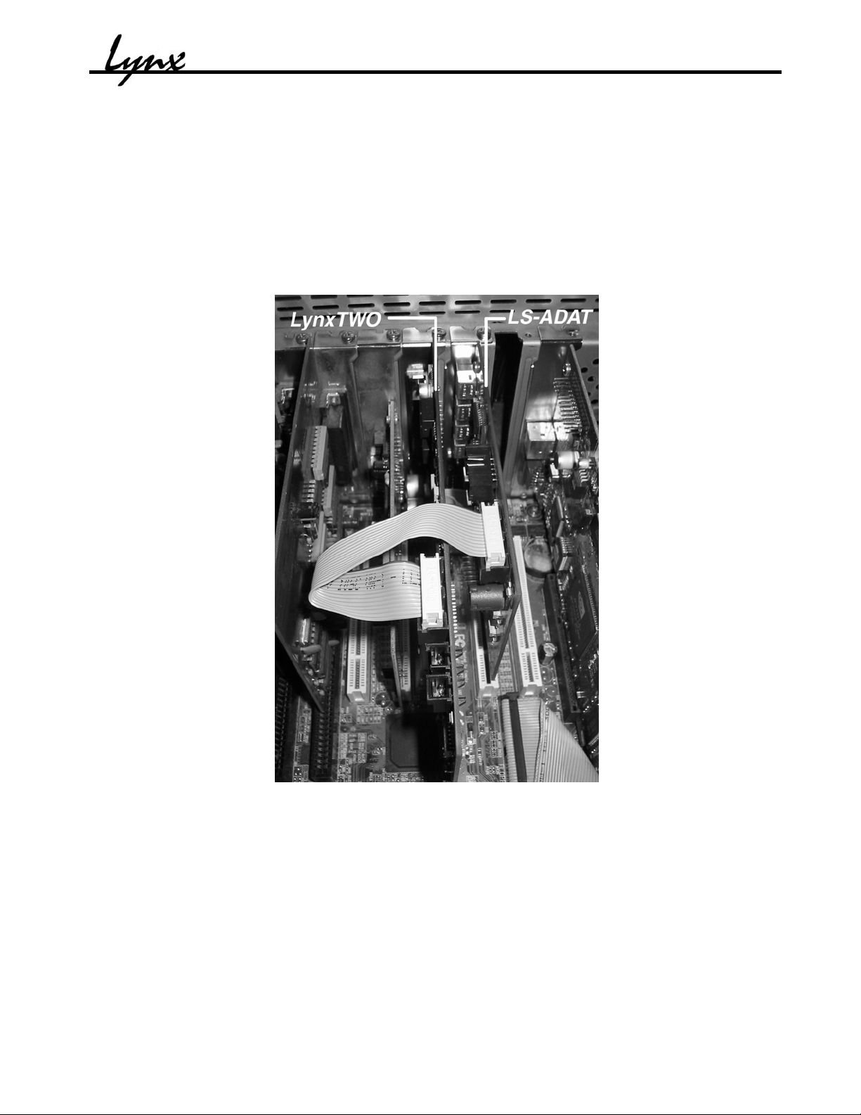
LS-ADA T Internal Card Installa tion
1. With your computer powered down, install the LS-ADAT in a bracket slot adjacent to the
LynxTWO/L22 as shown in the figure below. The LS-ADAT must be secured to the
computer chassis with a screw.
2. Connect the included 14-pin ribbon cable from connector JP1 on the LynxTWO/L22 to
connector JP2 on the LS-ADAT (labeled INT LSTREAM). The connectors on the ribbon
cable have polarizing tabs that insert into slots in the mating connectors. Insure that these tabs
are aligned correctly. Failure to do so may result in serious damage to the LynxTWO/L22
and LS-ADAT.
LynxTWO and LS-ADAT Installation in Computer Chassis
Page 5
Page 7

External Connections
The figure below depicts the layout of the LS-ADAT circuit board and its connectors.
LS-ADAT
IN 1
OUT 1
IN 2
OUT 2
ADAT Optical I/O
Header for ADAT 9-pin
SYNC IN D connector
(not shown)
JP2 - Internal
LStream Port
ADA T Optical Interface (lightpipe) Ports
The LS-ADAT provides two ADAT optical inputs and outputs. They are labeled on the mounting
bracket and in the figure above. The ADAT channels corresponding to each port are as follows:
IN 1 ADAT input channels 1-8
OUT 1 ADAT output channels 1-8
IN 2 ADAT input channels 9-16
OUT 2 ADAT output channels 9-16
Connect the LS-ADAT to ADAT devices in your system using standard ADAT compatible fiber
optic cables. Refer to the “Optional Equipment” section at the beginning of this manual for part
numbers of cables available from Lynx.
ADA T Sync In Port
The LS-ADAT provides an ADAT Sync In port labeled “SYNC IN” on the mounting bracket. (The
actual connector is not shown in the figure above). This port is used to interface to ADAT equipment
with a compatible Sync Out port for synchronization.
Connect this port to the Sync Out port of an external device using a 9-pin ADAT Sync Cable.
Page 6
Page 8

LS-ADAT
LynxTWO / L22 Mixer Controls
The LStream page of the LynxTWO/L22 Mixer contains controls for installed LStream interface
cards. With the LS-ADAT installed, ADAT-specific controls are displayed as shown below. The
description for each control is included for reference.
Device ID
Output Select
LStream device identification
Controls routing of the eight upper and lower
digital outputs from the host card to LStream
channels.
Clock Source
Position
Cue Point
All LStream controls are described in detail later in this manual.
Enable
Cue Point
Controls selection of the clock source for the
LS-ADAT.
Time code frame address decoded from ADAT
SYNC IN port. The frame rate is 30 fps.
Enables sample accurate time code
synchronization starting at the time code
address specified in the Cue Point box.
Text box for entry of time code Cue Point
frame.
LStream Interface to the Host L ynxTWO/L22
The LS-ADAT communicates with the host card through Lynx’s proprietary LStream interface.
LStream is a high-speed TDM serial interface that supports up to 16 channels of bi-directional 24-bit
audio data with synchronization and control information.
The individual channels of the LStream interface are integrated into the host card’s on-board digital
mixer. This allows LStream data, in this case ADAT data, to be freely routed and mixed with the host
card’s analog and digital audio I/O. Currently, the architecture of LynxTWO/L22 digital mixer
supports a maximum of 16 input and 16 output channels that can assigned as needed to the available
physical I/O’s. Controlling the digital mixer requires an understanding of the LynxTWO/L22 Mixer
application. Please refer to the User’s Guide included with the product you own for further details.
The number of channels supported on one LStream connection varies with sample rate as follows:
Sample Rate Speed Number of LStream
Channels
44.1/48 kHz Single 16
88.2/96 kHz Double 8
176.4/192 kHz Quad 4
It just so happens that the LStream channel capacity meets the requirements for handling the high
sample rate S/MUX features of the LS-ADAT. This will be discussed in more detail later.
Page 7
Page 9

LS-ADAT
LS-ADA T Output Routing
As shown below and in the Outputs page of the LynxTWO/L22 Mixer application, 16 output
channels are available from the digital mixer. Output channels 1-8 are wired to the analog outputs,
AES digital output, loopback registers, and to both LStream ports. Channels 9-16 are wired only to
LStream output channels. This connection scheme allows any (or all) of the digital mixer’s output
channels to be routed to the outputs of the LS-ADAT via the LStream interface. Please note, that the
signals sent to host card’s analog and digital outputs will be mimicked on the corresponding LSADAT channels if mixer outputs 1-8 are routed to the LS-ADAT.
LynxTW O A Model Output Sec tion
Monitor
Select
Monitor
Select
Monitor
Select
Monitor
Select
Optical Out 1
Optical Out 2
SUM
Mas ter
Fader
Output Submixer 1 - 16
D igital Mixer Ou tputs
LS-ADAT Output Sec tion
ADAT
XMIT
ADAT
XMIT
Peak
Dither
Level
ADAT Ch annels 1 - 8
ADAT Channels 9 - 16
Output 1 -16
Data Routing
S/M U X
Output 1 / 2
Output 3 / 4
Output 5 / 6
Output 7 / 8
Output 1 - 8
Output 9 - 16
Output 1 - 8
Output 9 - 16
&
L
R
L
R
Format
Pro/Con
Format
Format
Trim
+4 / - 10
Trim
+4 / - 10
DAC
DAC
Loopback
Registers
AES-3
XMIT
LStream 1 Transmitter
1-8 / 9-16
Select
Dual Intern al
1-8 / 9-16
Select
LS tream 2 Transmit t er
LStream
In Port
Analog O ut 1
Analog O ut 2
Analog O ut 3
Analog Out 4
D igital Out L /R
LStream 1
Brac ket Port
Output
LStream 2
Header Port
Output
LStream Channels 1 - 16
(Serial data on ribbon cable)
Output Channel Source Selection
As shown in the diagram, each digital mixer output channel is derived from a four-input submixer.
The inputs to the submixer are recording and playback signals that can be selected using the Output
Monitor Source select buttons. These buttons reside in the Outputs page of the LynxTWO/L22 Mixer
just above the faders for each output channel. Choose up to four sources for each output. The mute
button (labeled M) next to each Output Monitor Source button must be in the “out” position in order
for the signal to be heard.
Page 8
Page 10

LS-ADAT
LStream Output Channel Group Mapping
The mapping of the digital mixer’s output channels to LStream channels can be controlled to
accommodate specific I/O configuration requirements. The Output Select control (labeled “1-8/9-16
Select” in the diagram above) allows the destination of the upper eight and lower eight mixer output
channels to be altered. This feature is particularly useful for re-routing output channels 1 – 8, which
are hardwired to the host card’s analog and digital outputs and to the LStream ports.
The Output Select control on the LStream page of the LynxTWO/L22 Mixer has two settings:
9-16/1-8 Maps mixer output channels 9-16 to LStream output channels 1-8 AND maps mixer output
channels 1-8 to LStream output channels 9-16 (this is the default setting).
1-8/9-16 Maps mixer output channels 1-8 to LStream output channels 1-8 AND maps mixer output
channels 9-16 to LStream output channels 9-16.
Typically, the default setting is easiest to work with if you are using only the first eight channels of
the LS-ADAT. If you are using all 16 channels of the LS-ADAT at 48 kHz it may be easier to use the
1-8/9-16 option. In this case, the numbering of the output channels of the LynxTWO/L22 mixer
corresponds to the LS-ADAT output channel numbering.
Please note that this section pertains to the mapping of LStream channels, and not to LS-ADAT
output channels. As will be discussed in a later section there is not always a one-to-one
correspondence between LStream channels and LS-ADAT I/O channels.
Page 9
Page 11

LS-ADAT
LS-ADA T Input Routing
As shown below, the ADAT data from the LS-ADAT is routed into the digital mixer of the host card
via the LStream 2 Header port. This data can be routed to the record bus using the Input Source
Select function within each Input Submixer.
LynxTWO A Model Input Section
Record Bus
(16 Channels)
Optical In 1
Optical In 2
Peak
Level
Input Submix er 1 - 16
Dig ital Mixer Inputs
Input
MuteDither
Sel e ct
LS-ADAT Input Section
ADAT
RECV
ADAT
RECV
ADAT Channels 1 - 8
ADAT C hannels 9 - 16
Input 1 - 4 0
Data Routing
S/M U X
Input 1 / 2
Input 3 / 4
Input 5 / 6
Input 7/8
Input 9-24
Input 25-40
&
L
ADC
ADC
From output
loopback regis ters
SRC
LStream
Out Port
Trim
+4 / - 10
R
L
Trim
+4 / - 10
R
AES-3
RECV
LStream 1
Receiver
Dual I nternal
LStream 2
Receiver
Analog In 1
Analog In 2
Analog In 3
Analog In 4
Digital In L/R
Format
Pro/C on
LStream 1
Bracket Port
Input
LStream 2
Header Port
Input
LStream Channels 1 - 16
(Serial data on ribbon cable)
The Input Source Selection buttons on the Record/Play page of the LynxTWO/L22 Mixer provide
access to the input select function. These buttons are located just above the meters for each input
channel.
When these buttons are clicked, a menu containing the 40 possible input sources will be displayed.
To access channels from the internal version of the LS-ADAT, choose sources from LStream 2 In 1
through LStream 2 In 16.
Each Input Source is routed to either the left or right channel of a record device. The record device
number is located under the meters, e.g., Record 1, Record 2. When setting up for recording in an
audio editing application, these devices numbers are used to specify the recording source.
Page 10
Page 12

LS-ADAT
ADA T Channel Mapping and S/MUX
This section describes the mapping of LStream channels to LS-ADAT channels. This mapping varies
with sample rate since S/MUX is required to support sample rates above the standard ADAT sample
rate of 48 kHz.
At 44.1 kHz and 48 kHz there is a one-for-one correspondence between LStream channels and LSADAT channels. All 16 input and output channels are available.
At sample rates above 48 kHz, the signal channel capacity (and the number of required LStream
channels) is reduced since S/MUX utilizes multiple ADAT channels for each signal channel. Refer to
the following table.
88.1/96 kHz Sample Rate 176.4/192 kHz Sample Rate
LStream
Channel
1 1-2 1 1-4
2 3-4 2 5-8
3 5-6 3 9-12
4 7-8 4 13-16
5 9-10 16 – 5
6 11-12
7 13-14
8 15-16
16-9
S/MUX is enabled on demand, based on the sample rate currently selected for recording or playback.
As such, the mapping of channels will change when the sample rate changes. The user must be
keenly aware of this “automatic” re-mapping to avoid mixing and routing problems.
ADAT Channel LStream
Channel
NOT VALID
ADAT Channel
NOT VALID
Clock Synchronization
The ADAT Clock control on the LStream page of the LynxTWO/L22 Mixer provides LS-ADAT
clock source selection as follows:
Clock Source Selection Action
Slave LS-ADAT clock is slaved to the host card system clock source. The
system clock source is selected on the Adapter page of the Mixer.
Optical In 1 The word clock derived from optical IN 1 port is the clock source
for the LS-ADAT and host card.
Optical In 2 The word clock derived from optical IN 2 port is the clock source
for the LS-ADAT and host card.
Sync In The word clock derived from optical SYNC IN port is the clock
source for the LS-ADAT and host card.
Important: If a clock source other than Slave is used, the LynxTWO/L22 clock source must also be
set to LStream 2 in the Adapter page of the Mixer.
Page 11
Page 13

LS-ADAT
To insure glitch-free recording and playback using an external ADAT device, the LS-ADAT, host
LynxTWO/L22, and external ADAT must run synchronously from a common clock source. There are
only two scenarios to consider that satisfy this requirement:
1. The LynxTWO/L22 host card is the clock master. The LS-ADAT and external ADAT device
must run in clock slave mode. This case includes host card synchronization to external clocks
such as word clocks and composite video.
2. An external ADAT device is the clock master. The LS-ADAT clock source must be derived
from either of the optical inputs or ADAT sync input and the host card clock source must be
set to LStream 2.
Due to the high-jitter observed on clocks generated by ADAT recorders, we recommend that the
Slave clock source be used if possible. This choice utilizes the LynxTWO/L22 low-jitter sample
clock for all ADAT clocking. To run in this mode, the clock source of ADAT recorder must be set to
slave to its digital input (DIG IN) and either of the LS-ADAT’s optical outputs must be connect to
the ADAT’s optical input.
Select a clock source other than Slave if your system configuration does not allow the ADAT device
to run in clock slave mode or you wish to slave the LS-ADAT to an external device.
Synchronization with the ADAT Sync In Port
The LS-ADAT incorporates an ADAT compatible 9-pin Sync In port for synchronization to external
ADAT devices. The signals received on this port include ADAT system exclusive MIDI messages for
transport control functions, time code, and word clock. Most importantly, the received time code data
provides the mechanism for enabling sample-accurate transfers of audio data to and from an external
ADAT device.
The ADAT Sync In port feeds time code control logic on the LS-ADAT that provides two methods of
sample-accurate synchronization. In systems using ASIO compatible audio applications, the LSADAT utilizes Steinberg's ASIO Positioning Protocol for synchronization to ADAT time code.
Alternatively, synchronization using the LS-ADAT's Cue Point capability initiates recording or
playback with sample period resolution. The LS-ADAT also translates received time code to MTC
for general compatibility with many applications
ADAT synchronization requires the connection of a 9-pin cable from the Sync Out port of an external
ADAT device to the LS-ADAT Sync In Port.
ASIO Positioning Protocol Synchronization
ASIO specifies a sample count value for each audio data buffer to control sample position during
record or playback. When an ASIO application is running, the LS-ADAT will properly generate the
sample count for every buffer based on time code received from the SYNC IN port.
ASIO synchronization can be utilized in any ASIO compatible application that supports ASIO
Positioning Protocol. We have tested this with both Steinberg Nuendo and Cubase SX.
To enable ASIO Positioning Protocol in Nuendo and Cubase SX:
1. From the Transport menu select Sync Setup. In the Synchronization Setup dialog box, select
ASIO Positioning Protocol under Timecode Source.
Page 12
Page 14

LS-ADAT
2. From the Transport menu enable Sync Online.
With Positioning Protocol enabled, the ASIO application position cursor will track the time code
position of the external ADAT device with sample accuracy. Refer to documentation included with
your audio editing software for more information regarding ASIO synchronization.
Cue Point Synchronization
The Cue Point synchronization method relies on dedicated hardware in the LS-ADAT to detect a
match between a specified SMPTE frame address (the Cue Point) and time code data received on the
Sync In Port. When a match is detected, recording or playback is initiated in hardware, thus avoiding
delays inherent in software sync techniques.
This sync method can be used with most applications without altering settings within the
applications. The application is unaware that Cue Point is enabled.
To perform Cue Point sync:
1. Connect an ADAT machine to the Sync In Port of the LS-ADAT. Rewind the tape to a point
at least 5 seconds before the desired start position.
2. Start the audio application and determine the SMPTE frame address at which you would like
to start recording/playback. The frame must be referenced to a frame rate of 30 fps.
3. Launch the LynxTWO/L22 Mixer.
4. Insert the frame address from step 2 into the Cue Point text box on the LStream page. It must
be entered in hh:mm:ss:ff format exactly.
5. Check the Cue Point Enable box by clicking on it.
6. Start recording or playback normally in the audio application. At this point data will not be
transferred to /from the LynxTWO/L22. The application will be in a “paused stated” waiting
for a buffer transfer.
7. Press play on the ADAT recorder.
8. When the LS-ADAT receives the time code matching the Cue Point, it will initiate data buffer
transfers and in turn normal recording or playback activity will start in the audio application.
Cue Point Synchronization in Cool Edit Pro
The Sample Accurate Sync function in Cool Edit Pro (available from Syntrillium) interfaces with the
LS-ADAT’s Cue Point capability to provide a simplified synchronization setup. This feature
eliminates the requirement of manually inserting a Cue Point frame address and selecting Cue Point
Enable in the LStream page of the mixer. Refer to following instructions:
1. Connect an ADAT machine to the Sync In Port of the LS-ADAT. Rewind the tape to a point
at least 5 seconds before the desired start position.
2. Select Multitrack View in Cool Edit Pro (CEP) from the View menu.
3. Set the position cursor in CEP to the desired start position in the audio file.
4. From the Options menu select Sample Accurate Sync
5. Start playback in Cool Edit Pro
6. Press play on the ADAT recorder.
7. When the LS-ADAT receives the time code matching the cursor position, it will initiate data
buffer transfers and in turn start normal recording or playback in the CEP.
Page 13
Page 15

Specifications
ADAT OPTICAL I/O
Number / Type
Channels
Input Receiver
ADAT SYNCHRONIZATION I/O
Number / Type
Signals
Sample Accurate
Methods
MTC
MIDI
CLOCK SYNCHRONIZATION
Clock Sources
Modes
ARCHITECTURE
Core
Audio Devices
Routing/Mixing
CONNECTIONS
I/O Ports
Other
GENERAL
Host Interface
Requirements
EMI Certifications
Shipping Weight
Two inputs and two outputs, compatible with Alesis ADAT Type I and Type II
Optical Digital Interface Protocol, up to 24-bit data
16 @ 44.1kHz 48 kHz sample rates
8 @ 88.2 kHz and 96 kHz sample rates, S/MUX enabled
4 @ 176.4 kHz and 192 kHz sample rates, SMUX e nabled
Fast-locking phase-locked loop with 30 kHz to 55 kHz lock range
One 9-pin Sync In port compatible with Alesis Synchronization Protocol
Time code (sample count), word clock, and MIDI control data
ASIO Positioning Protocol and hardware-based SMPTE frame address matching
logic (Cue Point).
Time code to MTC conversion
MIDI port transfers serial input control data
Host card (LynxTWO or L22), Optical In 1, Optical In 2, ADAT Sync In
Master mode: utilizes LynxTWO or L22 low-jitter sample clock to drive external
ADAT devices
Slave mode: word clock derived from external ADAT device
FPGA-based core. Support for field upgrades of firmware.
Host Card is visible to applications as eight stereo record devices corresponding to
ADAT optical inputs 1 – 16 and eight stereo play devices corresponding to ADAT
optical outputs 1 – 16.
Integrates with host card’s digital mixer to allow independent routing of ADAT I/O
with host card analog and digital I/O.
(4) Bracket-mounted TOSLINK connectors. (1) 9-pin female D-sub connector.
LStream interface headers
Lynx proprietary LStream™ Interface: 24.5 Mbps bi-directional
One available bracket position (PCI slot not required), Host card: LynxTWO or L22
3.0” H X 5.0” W X 0.75” D
Size
FCC and CE
2 pounds
LS-ADAT
Page 14
Page 16

LS-ADAT
Support
We are devoted to making your experience with LS-ADAT trouble-free and productive.
If you have questions or comments regarding the operation of your LS-ADAT please check the
Troubleshooting topics on the Support section of the Lynx web site at:
http://www.lynxstudio.com/support.html
If you are unable to find information about your problem please email us at:
support@lynxstudio.com
In your email message include the following information:
• The serial number of your LS-ADAT and the serial number of your LynxTWO/L22.
• Which operating system you are using.
• The type of computer you are using.
• The name of the application you are using.
• A detailed description of the problem including any error messages you received.
We will provide a response in a timely manner.
Telephone support is available by calling (949) 515-8265, ext. 206 from 9AM to 5PM Pacific Time,
Monday through Friday, excluding Holidays. Please be sure to have the above information available
before calling.
Page 15
Page 17

LS-ADAT
License Agreement
This legal document is an agreement between you and Lynx Studio Technology, Inc. By opening the sealed board
package, or written materials, you are agreeing to become bound by the terms of the agreement, which includes this
License and Limited Warranty (collectively the “Agreement”). This Agreement constitutes the complete agreement
between you and Lynx Studio Technology, Inc. If you do no agree to the terms of the Agreement, DO NOT OPEN the
anti-static bag containing the LS-ADAT board. Promptly return the unopened package and all other items using the
original packaging to the location of purchase.
Limited Warranty
Lynx Studio Technology, Inc. (“Lynx”) warrants this product to be free of defects in material and workmanship for a
period of one year from the date of original retail purchase. This warranty is enforceable only by the original retail
purchaser. To be protected by this warranty, the purchaser must complete and return the enclosed warranty card within
14 days of purchase.
During the warranty period Lynx shall, at its sole and absolute option, either repair or replace free of charge any product
that proves to be defective on inspection by Lynx or its authorized service representative. In all cases disputes concerning
this warranty shall be resolved as prescribed by law.
To obtain warranty service, the purchaser must first call or write Lynx at the address and telephone number printed below
to obtain a Return Authorization Number and instructions concerning where to return the unit for service. All inquiries
must be accompanied by a description of the problem. All authorized returns must be sent to Lynx or an authorized Lynx
repair facility postage prepaid insured and properly packaged. Proof of purchase must be p resented in the form of a bill
of sale, canceled check or some other positive proof that the product is within the warranty period. Lynx reserves the
right to update any unit returned for repair. Lynx reserves the right to change or improve design of the product at any
time without prior notice.
This warranty does not cover claims for damage due to abuse, neglect, alteration or attempted repair by unauthorized
personnel, and is limited to failures arising during normal use that are due to defects in material or workmanship in the
product.
ANY IMPLIED WARRANTIES, INCLUDING IMPLIED WARRANTIES OF MERCHANTABILITY AND FITNESS
FOR A PARTICULAR PURPOSE, ARE LIMITED IN DURATION TO THE LENGTH OF THIS LIMITED
WARRANTY. Some states do not allow limitations on how long an implied warranty lasts, so the above limitation may
not apply to you.
IN NO EVENT WILL LYNX BE LIABLE FOR INCIDENTAL, CONSEQUENTIAL OR OTHER DAMAGES
RESULTING FROM THE BREACH OF ANY EXPRESS OR IMPLIED WARRANTY, INCLUDING, AMONG
OTHER THINGS, DAMAGE TO PROPERTY, DAMAGE BASED ON INCONVENIENCE OR ON LOSS OF USE OF
THE PRODUCT, AND, TO THE EXTENT PERMITTED BY LAW, DAMAGES FOR PERSONAL INJURY. Some
states do not allow the exclusion or limitation of incidental or consequential damages, so the above limitation or exclusion
may not apply to you.
This warranty gives you specific legal rights, and you may also have other rights which vary from state to state.
This warranty only applies to products sold in the United States of America or Canada. The terms of this warran ty and
any obligations of Lynx under this warranty shall apply only within the countr y of sale. Without limiting the foregoing,
repairs under this warranty shall be made only by a duly authorized Lynx service representative in the country of sale.
For warranty information in all other countries please refer to your local distributor.
Your warranty will be in effect and you will receive warranty information ONLY IF YOU REGISTER YOUR LSADAT as described in the “Warranty Registration ” sec tion .
Lynx Studio Technology, LS-ADAT and the LS-ADAT Logo are trademarks of Lynx Studio Technology, Inc. All other
product or company names are the trademarks or registered trademarks of their respective owners.
LS-ADAT™ Owner’s Manual, printed 7/29/2004
Page 16
Page 18

 Loading...