

Page 1
Page 2
/ L
A Message to Our Customers...
Thank You for choosing LYNX as your new gas grill. With proper use and care, we're confi-
dent that our product will provide years of trouble-free service. Careful attention has been put
into every detail of this grill and, by reading this entire manual before your first use, you will be
assured of maximum performance and enjoyment.
This manual also contains important safety tips and some hints for better grilling. Please keep it
in a convenient location so it will be available to answer any future questions. Should your LYNX
grill change ownership, please make sure that the new owner receives this manual.
We love to hear from our customers. Please feel free to contact us with any questions or prob-
lems, or to share a new recipe. Please include the model number of your grill inyour correspon-
dence. Thanks again for your purchase. Enjoy!
Page 3
This manuel covers the following 2008 Lynx products:
Installation, Care and Use
of Your Lynx Professional
Cooking Product
GRILL MODELS
L27 & L27F
L27R & L27FR
L30R & L3OFR
L36R & L36FR
L42R & L42FR LPSGE
PROSEAR MODELS
L3OPSR & L3OPSFR
L36PSR & L36PSFR
L42PSR & L42PSFR
L54PSR & L54PSFR
SIDE BURNER MODELS
LSB2PC
LSB1
LSB2
FOR OUTDOOR USE ONLY
IMPROPER INSTALLATION, ADJUSTMENT, ALTERATION, SERVICE OR MAINTENANCE
CAN CAUSE PROPERTY DAMAGE, INJURY OR DEATH. READ THIS MANUAL
THOROUGHLY BEFORE INSTALLATION, USE OR SERVICING OF THIS EQUIPMENT
CALIFORNIA PROPOSITION 65 WARNING
The burning of gas cooking fuel generates some by-products, which are on the list of substances, which are
known by the State of California to cause cancer or reproductive harm. California law requires businesses to
warn customers of potential exposure to such substances.To minimize exposure to the substances, always
operate this unit according to the use and care instructions found in this manual. Be certain to provide
adequate ventilation when cooking. California Proposition 65 lists "Silica, crystalline"which is used in one of
the components of the IR burner, asan agent known to the state of California to cause cancer.
NOTE TO INSTALLER
This manual must remain with grill. Check your local building codes for proper method of installation. In
the absence of local codes, this unit should be installed in accordance with National Fuel Gas Code No. ANSI
Z21.58D-2002 USA or CAN/CGA-B149.1/.2 Natural Gas/Propane Code.(Canada) latest edition or the National
Electrical Code ANSI/NFPA No. 70 or the Canadian Electrical Code CGA 1.662005 or latest edition.
In Massachusetts: All gas products must be installed using a" Massachusetts" licensed
plumber or gas fitter. A'T" handle type manual gas valve must be installed in the gas supply
line to this appliance.This applies to permanently installed natural gas and propane instal-
lations. This does not apply to propane portable installations using a 20 pound tank (not
included) plus regulator and hose assembly, which is supplied with propane gas grills.
Rev. 12-07
Page 4
Important Safety Considerations
WARNING!Read this manual carefully and completely before using your grill to reduce the risk of fire, burn
hazard or other injury, and to ensure proper installation and servicing.
FOR YOUR SAFETY
If you smell gas:
1. Shut off gas to the appliance.
2. Extinguish any open flames.
2. Open lid.
4. If odor continues, keep away from the
appliance and immediately call your gas
supplier or fire department.
FOR YOUR SAFETY
1. Do not store or use gasoline or other flam-
mable vapors and liquids in the vicinity of
this or any other appliance.
2. An LP cylinder not connected for use shall
not be stored in the vicinity of this or any
other appliance.
AVERTISSEMENT
S'ily a une odeur de gaz:
1.Coupez I'admission de gaz de I'appariel.
2. leteindre toute flamme nue.
3.Ouvrir le couvercle.
4. Si I'odeur continue, evite I'appareil et appelle
tout de suite votre fournisseur de gaz ou les
pompiers.
AVERTISSEMENT
1. Ne pas entreposer ni utiliser de I'essence ni
d'autres vapeurs ou liquides inflammables
dans le voisinage de I'appareil, ni de tout
autre appareil.
2. Une bouteille de propane qui n'est pas
raccordee en vue de son utilisation, ne doit
pas _tre entreposee dans le voisinage de cet
appareil ou de tout autre appareil.
FOR OUTDOOR USE ONLY: If stored
indoors, detach and leave L.P. cylinder
outdoors.
BEFORE LIGHTING
1. Read instructions before lighting.
2. Open lid during lighting.
3. If ignition does not occur in 5 seconds, turn
the burner control(s) off, wait 5 minutes, and
repeat the lighting procedure.
B_LyNX
POUR UTILISATION A L'EXTCRIEUR
SEULEMENT: Si I'appareil est entrepos_
I'interieur, enlever les bouteilles et les
laisser _ I'ext_rieur.
AVANT D'ALLUMER
L'APPAREIL
1. Lisez les instructions avant d'allumer I'appareil.
2.Ouvrez le couvercle avant d'allumer I'appareil.
3. Si I'appareil ne s'allume pas en 5 secondes,
fermez le robinet du brOleur, attendez 5 min-
utes, et procedez de nouveau a I'allumage.
Page 5
Table of Contents
Precautions for Installation and Storage ............................................................. 2
Locating Your Grill ................................................................................. 4
Cutout Dimensions for 2008 Built-ins ............................................................... 5
Unpacking and Assembly .......................................................................... 6
Electrical Requirements & Hook-up ................................................................. 7
Gas Requirements & Hook-up ...................................................................... 8
Precautions for Using Your Grill ................................................................... I 0
LeakTesting ..................................................................................... 11
Model Identification ............................................................................. 12
Using the Grill ................................................................................... 13
Lighting the Brass Burners ........................................................................ 14
Using the ProSear Burner ......................................................................... I 5
Using the Rotisserie .............................................................................. 16
Using the Smoker Box ............................................................................ 17
Cleaning the Grill ................................................................................ 18
Burner Cleaning & Adjustment ................................................................... 19
Troubleshooting ................................................................................. 20
Light Bulb Replacement .......................................................................... 21
Replacing the Briquettes ......................................................................... 21
Side Burner/LPSGE Gas Hookup .................................................................. 22
Lighting the Side Burner or LPSGE................................................................ 23
Warranty ........................................................................................ 24
How to Obtain Service ........................................................................... 25
Wiring Diagrams .............................................................................. 26-27
Gas Plumbing Requirements ..................................................................... 28
Parts Diagram .................................................................................... 29
Parts List ......................................................................................... 30
IF SHIPMENT ARRIVES DAMAGED:
1) VISIBLE LOSSOR DAMAGE: Be certain this is noted on freight bill or express receipt and signed by
person making delivery.
2) FILE CLAIM FOR DAMAGES IMMEDIATELY, regardless of extent of damage.
3) CONCEALED LOSSOR DAMAGE: If damage is unnoticed until merchandise is unpacked, notify
transportation company or carrier immediately and file "concealed damage"claim with them.This
should be done within (15) days of date delivery is made to you. Be sure to retain container for
inspection. We cannot assume responsibility for damage or loss incurred in transit.
See page 25 for information on obtaining service or contacting Lynx.
B _lyNX
Page 6
Precautions for Installation and Storage
I) DO NOT store or use gasoline
or other flammable vapors and
liquids in the vicinity of this or
any other appliance.
2) Never store additional or
empty propane cylinders in the
grill cabinet or around the grill.
Do not store propane cylinders
indoors or on their sides. Never
use dented, rusty or damaged
propane cylinders.
3) Children should not be left
alone or unattended in an area
where a grill is located. Placeyour
grill well away from areas where
children play. Do not store items
that may interest children in or
around the grill, in the cart or in
the masonry enclosure. When in
use, portions of the grill are hot
enough to cause severe burns.
4) Never move the grill when hot.
S) Always adhere to the required
clearances from combustibles as
detailed. The grill is designed for
outdoor use only. Never use in a
garage, building, shed, breeze-
way or other enclosed area.
6) Gas grills are not design cer-
tified for and are not to be
installed in or on recreational
vehicles, portable trailers, boats
or any other moving installation.
7) Have an ABC Fire Extinguisher
accessible -- never attempt to
extinguish a grease fire with
water or other liquids.
8) Store your grill in a well-ven-
tilated area. Remove the L.P.cyl-
inder, if so equipped, and store
it outdoors in a well-ventilated
area away from heat and away
from where children may tam-
per with it.
9) Keep any electrical supply
cord and the fuel supply hose
away from any heated surfaces.
Electrical cords should be placed
away from walkways to avoid
tripping hazard.
10) Do not repair or replace
any part of the grill unless spe-
cifically recommended in this
manual. Other service should be
performed by a qualified tech.
11) If the grill is installed by a
professional installer or techni-
cian, be sure that he shows you
where your gas supply shut-off is
located. All gas lines must have
a shut-off that is readily and eas-
ily accessible. If you smell gas,
check for gas leaks immediately.
Check only with a soap and
water solution. Never check for
gas leaks with an open flame.
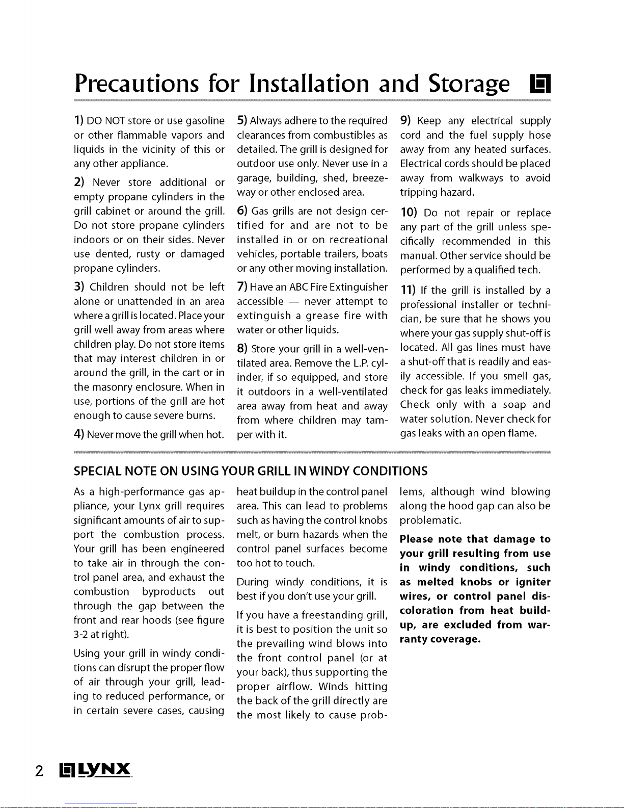
SPECIAL NOTE ON USING YOUR GRILL IN WINDY CONDITIONS
As a high-performance gas ap-
pliance, your Lynx grill requires
significant amounts of air to sup-
port the combustion process.
Your grill has been engineered
to take air in through the con-
trol panel area, and exhaust the
combustion byproducts out
through the gap between the
front and rear hoods (see figure
3-2 at right).
Using your grill in windy condi-
tions can disrupt the proper flow
of air through your grill, lead-
ing to reduced performance, or
in certain severe cases, causing
heat buildup in the control panel
area. This can lead to problems
such as having the control knobs
melt, or burn hazards when the
control panel surfaces become
too hot to touch.
During windy conditions, it is
best if you don't use your grill.
If you have a freestanding grill,
it is best to position the unit so
the prevailing wind blows into
the front control panel (or at
your back), thus supporting the
proper airflow. Winds hitting
the back of the grill directly are
the most likely to cause prob-
lems, although wind blowing
along the hood gap can also be
problematic.
Please note that damage to
your grill resulting from use
in windy conditions, such
as melted knobs or igniter
wires, or control panel dis-
coloration from heat build-
up, are excluded from war-
ranty coverage.
2 B_lyNX
Page 7
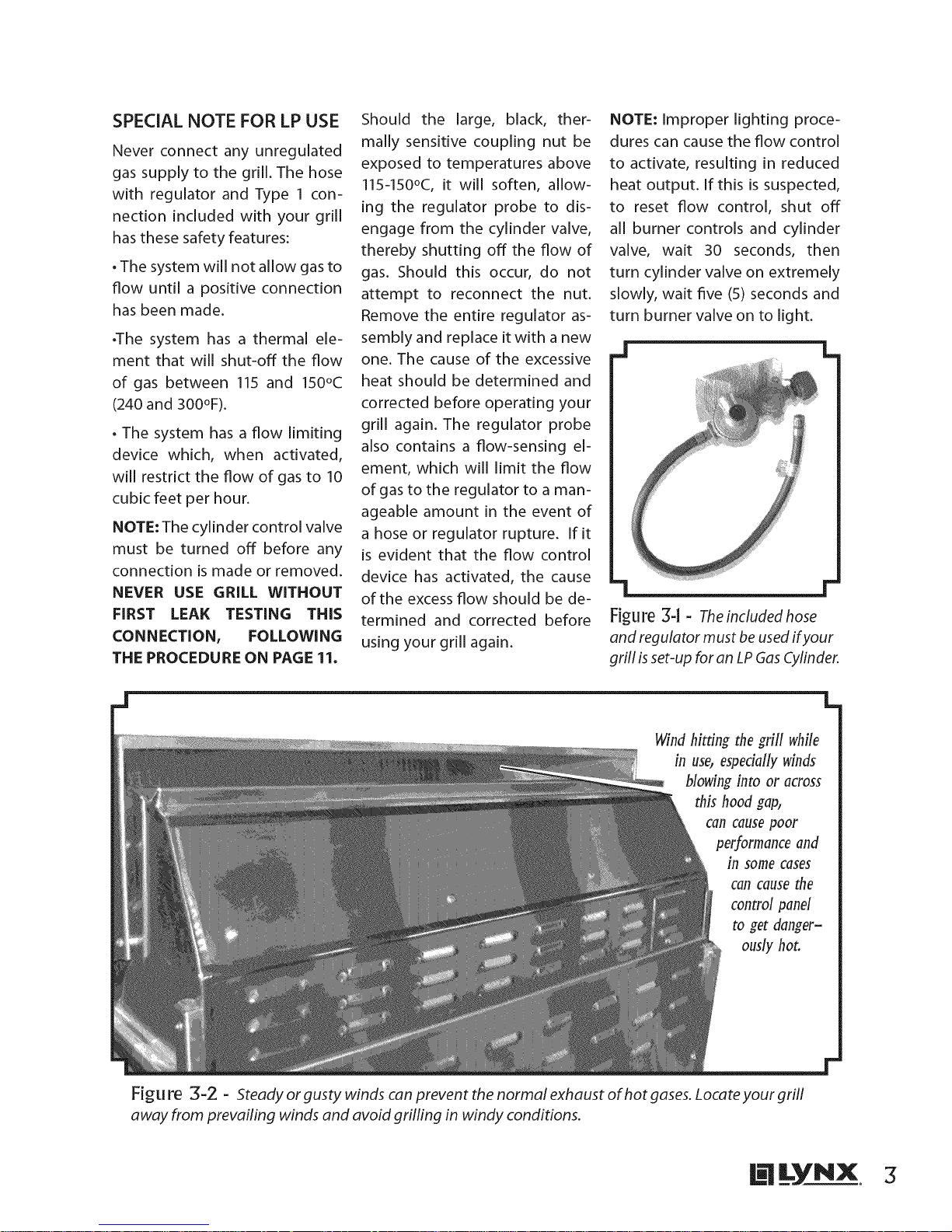
SPECIAL NOTE FOR LP USE
Never connect any unregulated
gas supply to the grill. The hose
with regulator and Type 1 con-
nection included with your grill
has these safety features:
. The system will not allow gas to
flow until a positive connection
has been made.
.The system has a thermal ele-
ment that will shut-off the flow
of gas between 115 and 150°C
(240 and 300°F).
. The system has a flow limiting
device which, when activated,
will restrict the flow of gas to 10
cubic feet per hour.
NOTE: The cylinder control valve
must be turned off before any
connection is made or removed.
NEVER USE GRILL WITHOUT
FIRST LEAK TESTING THIS
CONNECTION, FOLLOWING
THE PROCEDURE ON PAGE 11.
Should the large, black, ther-
mally sensitive coupling nut be
exposed to temperatures above
115q50°C, it will soften, allow-
ing the regulator probe to dis-
engage from the cylinder valve,
thereby shutting off the flow of
gas. Should this occur, do not
attempt to reconnect the nut.
Remove the entire regulator as-
sembly and replace it with a new
one. The cause of the excessive
heat should be determined and
corrected before operating your
grill again. The regulator probe
also contains a flow-sensing el-
ement, which will limit the flow
of gas to the regulator to a man-
ageable amount in the event of
a hose or regulator rupture. If it
is evident that the flow control
device has activated, the cause
of the excess flow should be de-
termined and corrected before
using your grill again.
NOTE: Improper lighting proce-
dures can cause the flow control
to activate, resulting in reduced
heat output. If this is suspected,
to reset flow control, shut off
all burner controls and cylinder
valve, wait 30 seconds, then
turn cylinder valve on extremely
slowly, wait five (5) seconds and
turn burner valve on to light.
J L
l-
Figure 3-1 - Theincludedhose
and regulator must be used ifyour
grill isset-up for an LP GasCylinder.
Wind hitting the grill while
in use, especially winds
blowing into or across
this hood gap,
Call cause poor
performance and
in some cases
can cause the
control panel
ous/y hot.
Figu re 3-2 - Steady or gusty winds can prevent the normal exhaust of hot gases. Locate your grill
away from prevailing winds and avoid grilfing in windy conditions.
@LYNX 3
Page 8

Locadng Your GH
When selecting a suitable loca-
tion, take into account concerns
such as exposure to wind and
traffic paths. Try to keep all gas
supply lines as short as possible.
Never locate the grill under a
roof or overhang, in a build-
ing, garage, shed or other such
enclosed area. A carpenter's
"spirit level" should be used to
assure that the unit is level both
front-to-back and side-to-side.
If it is not level, burner combus-
tion may be erratic or the unit
may not function efficiently. If
the floor is uneven or has a de-
cided slope, re-leveling may be
required after each moving of a
freestanding unit.
BUILT-IN INSTALLATIONS:
The LYNX Built-In Grill is designed
for easy installation into mason-
ry enclosures. For non-combus-
tible applications, the grill drops
into the opening shown in the
cutout detail drawing and hangs
from its counter-top trim. A deck
isnot required to support it from
the bottom. When using the in-
sulated jacket in a combustible
enclosure, the jacket must be
supported from the bottom by a
ledge on each side or a full deck
beneath the jacket. Review the
detailed drawing and pay spe-
cial attention to the provisions
shown for gas line hook-up. It is
recommended that the enclo-
sure have ventilation holes to
prevent gas build-up inthe event
of a leak. The deck ledges and
counter should be flat and level.
If your grill isequipped with a to-
tisserie, electrical service should
be provided (on the Left Side of
most models).
REARHOOD CLEARANCE:
Clearance is required behind the
grill to allow the front hood to
open (see figure 4q). 27" and 36"
models require a minimum of 2"
clearance, while 30", 42" and 54"
models require a minimum of
4" clearance. The grill exhausts
combustion products and cook-
ing greases to the back. Never lo-
cate the grill where this exhaust
will be difficult to clean.
2" rain. for 27" grills
4" rain. for all other sizes
Figu re 4-1 - Requireddearance
to allow opening of front hood.
CLEARANCE TO COMBUSTIBLE
CONSTRUCTION:
Minimum clearance from sides
and back of unit to adjacent
combustible construction below
top of unit are 12" from sides and
12"from back.
D_gagement minimal entre les
parois lat_rales et I'arri¢re de
I'appafiel et la construction com-
bustible au-dessous du panneau
sup_fieur de I'appareil (30 cm
partir des parois lat_rales et 30 cm
partir de I'arri¢re).
Minimum horizontal clearance
from sides and back of unit to
adjacent vertical combustible
construction extending above
top of unit is 12" from sides and
12"from back.
D_gagement horizontal minimal
entre les parois lat_rales et I'arri¢re
de I'appafiel et la construction
verticale combustible au-dessus
de I'appareil (30 cm _ partir des
parois lat_rales et 30 cm _ partir
de I'arfi¢re).
Do not use this appliance under
overhead combustible surfaces.
Ne pas u_'liser cet appareil sous
une surface combustible.
A minimum of 6" of clearance is
needed on each side of the grill
for the motor and skewer.
If the grill is to be placed into
a combustible enclosure, an
approved insulated jacket is
necessary and isavailable from
your LYNX dealer. Use only a
LYNX insulated jacket as it
has been designed and tested
specifically for your Grill. Refer
to next page for cutout dimen-
sions.
WARNING
Installing this product
into a combustible en-
closure without an insu-
lated jacket could result
in fire, property damage
and personal injury.
4 lil YNX
Page 9
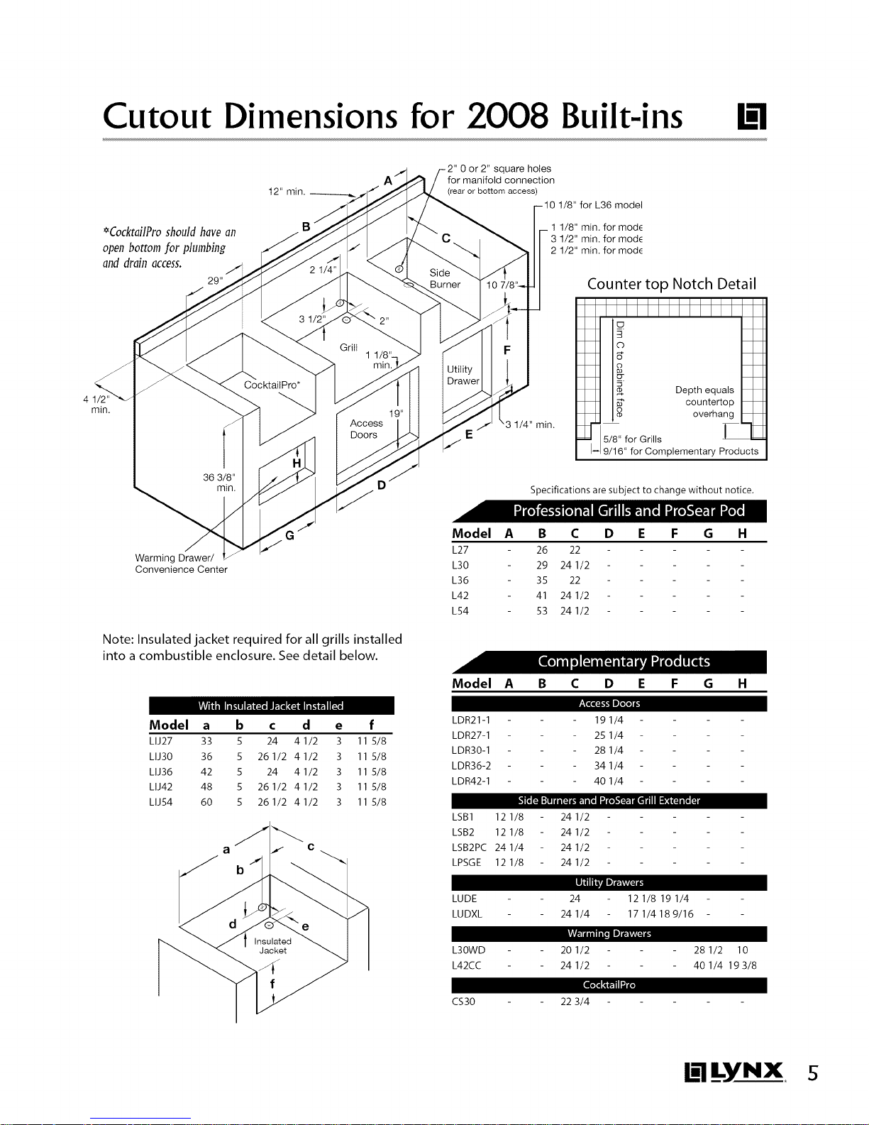
Cutout Dimensions for 2008 Built-ins
0 or 2" square holes
for manifold connection
(rear or bottom access)
*CocktailPro should have an
open bottom for plumbbg
and drain access.
2g"
1/8" for L36 model
1 1/8" min. for mod_
3 1/2" min. for mod_
2 1/2" min. for mod_
Counter top Notch Detail
IIIIIIIIIIII1
41/2"
min.
Warming Drawer/
Convenience Center
Note: Insulated jacket required for all grills installed
into a combustible enclosure. See detail below.
Model a b c d e f
LIJ27 33 5 24 4 1/2 3 11 5/8
LIJ30 36 5 261/2 41/2 3 11 5/8
LIJ36 42 5 24 4 1/2 3 11 5/8
LIJ42 48 5 26 I/2 4 I/2 3 11 5/8
LIJ54 60 5 26 1/2 4 1/2 3 11 5/8
b
O DecPthur_q _taol; I_
] o overhang I_t
_r 5/8. for Grills _-_ TM
--I 9/16" for Complementary Products
Specifications are subject to change without notice.
Model A B C D E F G H
L27 26 22
L30 29 24 1/2
L36 35 22
L42 41 24 1/2
L54 53 24 1/2
Model A B C D E F G H
LDR21-1
LDR27-1
LDR30-1
LDR36-2
LDR42-1
_Jl__l [_lll_fl
LSB1 12 1/8
LSB2 12 1/8
LSB2PC 24 1/4
LPSGE 12 1/8
191/4
251/4
281/4
341/4
401/4
24 1/2
24 1/2
24 1/2
24 1/2
_I_ID_
LUDE
LUDXL
24
24 I/4
12 I/8 19 I/4
17 I/4189/16
L30WD
L42CC
CS30
20 I/2
24 I/2
22 3/4
28 I/2 10
40 1/4 19 3/8
B_lyNX s
Page 10
Unpacking and Assembly
Your grill arrives nearly ready to
use and requires little assem-
bly. By carefully following these
steps, you will be assured of safe
initial operation.
1) Cut the main strap holding
the grill to the pallet. With as-
sistance, remove grill from pallet
and place into desired location.
2) Carefully cut the cable ties
securing the warming rack and
rotisserie spit (if equipped). Re-
move these parts and set aside.
3) Remove the grill racks, then
remove any loose items from the
firebox, including the rotisserie
motor and L.R hose.
4) Carefully remove the bri-
quette trays by lifting the front
of the tray and sliding it towards
the front of the grill.
S) Inspect briquette trays for
loose or missing briquettes. If
found, follow procedure at right
to reinstall.
6) Cut and remove wire and/or
cable ties from burners. ProSear
burners may be secured from the
bottom side. Remove styrofoam
block from under ProSear burner
cover. Ensure that all burners are
properly in line with and seated
on the burner valve orifice.
7) On ProSear models, cut and
remove ties from the burner
partition on the left side of the
ProSear burner.
8) Re-install briquette trays by
reversing procedure from step 4.
9) Re-install grill racks.
You are now ready to proceed
with the utility connections.
TO REPLACE BRIQUETTES
The special Lynx ceramic bri-
quettes are secured to the trays
with stainless steel clips. To in-
sert a briquette into the tray, it
is necessary to remove the clip
from one side of the empty slot.
This is done by bending the re-
taining tabs for the clip located
on the back side of the briquette
tray as shown below.
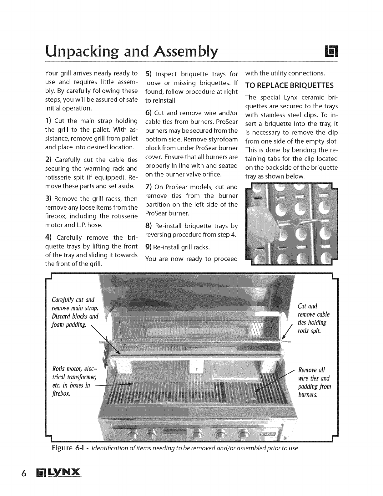
F[gu re 6-1 - Identification of items needing to be removed and/or assembled prior to use.
6 @LYNX
Cut and
remove cable
ties holding
rotis spit.
Removeall
wireties and
burners,
Page 11
Electrical Requirements Hook-up
WARNING
Electrical Grounding
Instructions:
This outdoor gas cooking appli-
ance is equipped with a three-
prong (grounding) plug for your
protection against shock hazard
and should be plugged directly
into a properly grounded three-
prong outlet. Do not cut or remove
the third prong from this plug.
AVERTISSEMENT
Instruction pour la mise _ la
terre electrique:
Cet appareil est muni d'une fiche
trois broches (mise _ la terre) afin
de vous prot_ger des chocs et dolt
_tre branch_ directement dans une
prisede courant _ trois broches ad_-
quatement mise _ la terre, line faut
pas couper ou enlever la broche de
mise _ la terre de cette fiche.
CONNECTION TO AC
Installation should include an
outdoor 120VAC 15A GFI electri-
cal outlet located adjacent to the
grill. A qualified electrician can
install a GFI outlet either inside
the island enclosure for built-in
units, or near the normal location
of use for freestanding units. The
GFI plug has an internal breaker
which reduces shock hazard.
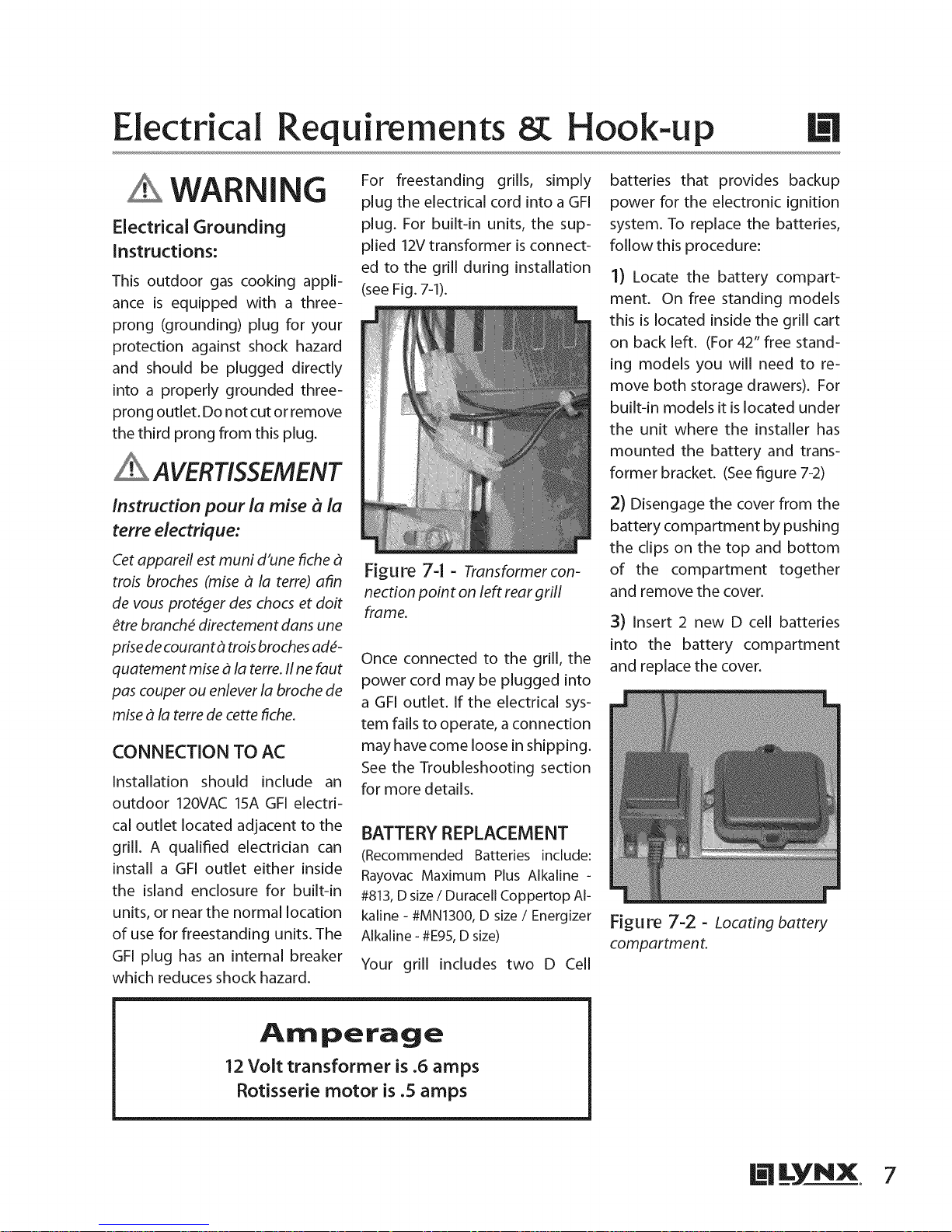
For freestanding grills, simply
plug the electrical cord into a GFI
plug. For built-in units, the sup-
plied 12Vtransformer is connect-
ed to the grill during installation
(see Fig. 7-1).
Figure 74 - Transformer con-
nectionpoint on left rear grill
frame.
Once connected to the grill, the
power cord may be plugged into
a GFI outlet. If the electrical sys-
tem fails to operate, a connection
may have come loose in shipping.
See the Troubleshooting section
for more details.
BATTERY REPLACEMENT
(Recommended Batteries include:
Rayovac Maximum Plus Alkaline -
#813,D size/Duracell Coppertop Al-
kaline - #MN1300, D size/ Energizer
Alkaline - #E95,D size)
Your grill includes two D Cell
batteries that provides backup
power for the electronic ignition
system. To replace the batteries,
follow this procedure:
1) Locate the battery compart-
ment. On free standing models
this is located inside the grill cart
on back left. (For 42" free stand-
ing models you will need to re-
move both storage drawers). For
built-in models it is located under
the unit where the installer has
mounted the battery and trans-
former bracket. (See figure 7-2)
2) Disengage the cover from the
battery compartment by pushing
the clips on the top and bottom
of the compartment together
and remove the cover.
3) Insert 2 new D cell batteries
into the battery compartment
and replace the cover.
Figure 7-2 - Locating battery
compartmen t.
Amperage
12 Volt transformer is .6 amps
Rotisserie motor is .5 amps
Page 12

Gas Requirements Hook-up
Your grill is setup to use either
propane (LP)or natural gas (NAT).
It is very important that the
grill rating plate matches
with your gas supply.
The rating plate is located in one
or more of the following places:
• under the drip tray
• on the heat shield behind the
front panel
• on the inside left cabinet wall
(most freestanding grills)
Do not attempt to operate the
grill on any gas other than what
the grill is orificed for and what
the regulator is set for. Should
you need to convert your grill
for use with a different gas type,
a conversion kit, available from
your dealer, is required.
Never connect an unregu-
lated gas line to the grill.
so as to calculate what size diam-
eter pipe is needed, for the total
length of pipe from the gas main
(at house) to grill hook-up. If the
gas line is too small, the grill will
not function properly. In no case
should pipe less than 3/4" in-
side diameter or 1" outside
diameter be used to connect
this product.
An installer-supplied gas
shut-off valve must be in-
stalled in an easily acces-
sible location. All install-
er-supplied parts must
conform to local codes
with the National Electrical
Code, ANSI/NFPA 70-1990
and the National Fuel Gas
Code, ANSI Z21.58D-2002.
The appliance and its individual
shut off valve must be discon-
nected from the gas supply
piping system during any pres-
sure testing of that system at
test pressures above 1/2" PSIG
(3.5KPA). The appliance must
be isolated from the gas supply
piping system by closing its in-
dividual manual shut off during
any pressure testing. Do not ap-
ply threading compound to the
first two pipe threads as to avoid
clogging of the burner valves
and orifice. Do not put sealant
on any male end of flare fittings.
For built-in installations, it is rec-
ommended that anyflexible pipe
used be kept as short as possi-
ble. For freestanding units using
natural gas, it is strongly recom-
mended that a quick disconnect
kit from Lynx be installed. This
kit, part #LQD, is available from
,our dealer.
IMPORTANT- See Gas
Plumbing Requirements
on page 28 for additional
information
NATURAL GAS
The installation of the grill must
conform with local codes or, in
the absence of local codes, to
the National Fuel Gas Code ANSI
Z21.58D-2002 or latest edition. If
installed in Canada, installation
must be in accordance with Gas
Code CAN / CGA-B149.1/.2 and
local codes.
The gas supply line must be
sized to accommodate all the
gas-fired equipment that may
be connected to that supply,
i.e. total BTU output to be con-
sumed, needs to be determined
8 B_lyNX
Fittingsshown below are for a
typicd installation and are not
supplied with the grill. As each
installation may require differ-
ent plumbing, Lynx recomlnends
that this step be performed by
a qualified technician.
Male to 3/4" Female elbow
Incoming natural
as supply pipe
Shut-off valve
Convertible Regulator --
supplied with gril!
(Gas type conversion
requires conversion kit -
contact dealer for details)
3/4" Min. Dia.
flexible connector
NPT
J
Figu re 8-1 - Typical attachment for using natural gas.
L
Page 13

L.P. GAS
Grills orificed for use with L.P.gas
come equipped with an LP hose/
regulator assembly for connec-
tion to a standard 20 lb. L.P.cyl-
inder (Type 1).All fttings neces-
sary to attach the hose/regulator
to the grill are included. The L.P.
tank is not included. Operating
pressure: 11.0" W.C.
L.P.Tank Requirements
A dented or rusty L.P.tank may
be hazardous and should be
checked by your L.R supplier.
Never use a cylinder with a dam-
aged valve. Always check for
leaks after every L.Rtank change
(see page 11).
The L.R gas cylinder must be
constructed and marked in ac-
cordance with the specifications
for L.R gas cylinders of the U.S.
Department of Transportation
(DOT) and designed for use with
a Type 1 system only. Do not
change the regulator/hose as-
sembly from that supplied with
the unit or attempt to use a
5LP-A equipped regulator/hose
assembly with a standard 510
POL tank/valve assembly. The
cylinder must be provided with
a shut off valve terminating in
an L.R gas supply cylinder valve
outlet specified, as applicable,
for connection Type 1.
Turn off LP-gas supply at cylinder
when appliance is not in use.
Fermez I'alimentation en GPL
la bouteille si I'appareil ne fonc-
tionne pas.
The LP-gas supply cylinder must
be disconnected when this ap-
pliance is not in use.
La bouteille de GPL doit _tre d_-
connect_e si cet appareil ne fonc-
tionne pas.
Your local L.P. filling station
should be equipped with the
proper equipment to fill your
tank. If trading your tank in,
always ensure to obtain only
Type 1 201b cylinders with an
overfill protection device.
L.P.Connections
Connect the 3/8"flare end of the
L.R hose to the brass adapter on
the manifold (as shown in fig-
ure 9-1). Connect the Regulator
to the tank (with the tank valve
fully closed). Although the flow
of gas is stopped when the Type
1 system is disconnected, you
should always turn the L.R tank
main valve off after each use
and during transport of the tank
or unit. Insert the regulator inlet
into the tank valve and turn the
black coupler clockwise until the
coupler is tight. Do not over-
tighten the coupler.
To disconnect the coupler, first
make sure the main tank valve
is turned off. Grasp the coupler
and turn counter clockwise. The
inlet will then disengage.
For hard plumbed LP connec-
tions to a large source (tank), a
4/11 regulator must be utilized.
Never connect an unregulated
gas line to the grill.
Gas Line Purging
To purge the L.P.gas line, make
sure all controls are in the OFF
position. Turn the main tank
valve on SLOWLY and turn one
burner control valve on the unit
to the "light" position (DO NOT
LITE GRILL). Leave control ON for
about 20 seconds to allow the
air in the system to purge. Wait
5 minutes before attempting to
light the burners.
Do not attempt lighting the grill
within 5 minutes after purging!
Use regulator here for L
hard-plumbed L.P.hookup
(LYNX P/N 30781)
L.Rhose/regulator
Cylinders must be stored
outdoors in a well-ventilat-
ed area out of the reach of
children. If the appliance
is stored indoors, the L.R
cylinder must be removed
from the appliance, and
stored outside.
3/8"flare fitting (hose ships
pre-installed on grill)
1
20 Ib.Type 1 L.P.tan
Figure 9-1 - Typical attachment to L.Rtank.
B_lyNX 9
Page 14

Precautions for Using Your Grill
READ THIS MANUAL CARE-
FULLY AND COMPLETELY
BEFORE USINGYOURGRILL
TO REDUCE THE RISK OF
FIRE, BURN HAZARD OR
OTHER INJURY.
Safety Precautions
1)NEVER LEAVE THE GRILL UN-
ATTENDED WHILE COOKING.
2) Prior to using grill ensure that
all tie down wires have been re-
moved from burners.
3) Never operate the grill in a
windy area. See page 2 for de-
tails.
4) Avoid wearing loose-fitting
garments or long sleeves while
using the grill. Never touch the
grill racks, hood or immediate
surrounding metal surfaces with
your bare hands as these areas
become extremely hot during
use and could cause burns.
S) Use an insulated glove or mitt
when opening and operating
the grill. Open grill lid slowly to
allow heat and smoke to escape
before fully opening.
6) Never lean over hot grill sur-
face or look directly into the grill
when attempting to light. The
grill hood must be fully opened
when lighting.
7) Do not heat unopened food
containers as pressure build-up
may cause container to burst.
8) Do not use aluminum foil to
line grill racks or drip pans. This
will alter combustion airflow or
trap excessive heat in the control
area. This can result in melted
knobs and ignition modules.
Never cover or block grilling area
with anytype of pots and/or pans.
These damages are specifically
excluded from your warranty.
9) Never use charcoal in the grill.
10) Be aware that cooking exces-
sively fatty meats and other such
products will cause flare ups.
Internal fires or damage caused
by flare-ups or the grill being left
unattended while cooking, are
not the responsibility of LYNX
and any resulting damage is not
covered under the terms and
conditions of our warranty.
11) Never grill without the drip
pan in place. The drip pan must
be pushed all the way to the back
of the grill. Without the drip pan
in place, hot grease could leak
downward and produce a fire or
explosion hazard.
12) Grease is extremely flam-
mable. Let hot grease cool down
before attempting to handle
or dispose of it. The drip tray
should be cleaned of grease on
a regular basis.
13) Do not use the grill until a
leak check has been performed
(see page 11).
14) Do not operate grill under
the influence of alcohol or drugs.
15) If equipped, never place
more than 30 pounds on a side
shelf. Do not lean on shelves.
16) If any burner does not light
or goes out during operation,
turn off all gas control knobs
with hood open and wait five (5)
minutes before attempting to
re-light.
WARNING
Spiders and insects can
nest in the burners of
this or any other grill,
and cause gas to flow
from the front of the
burner. This is a very
dangerous condition
which can cause a fire to
occur behind the valve
panel, thereby damag-
ing the grill and making
it unsafe to operate.
If your grill has been
stored or unused for a
prolonged period, it is
recommended that the
burners be removed, in-
spected, and cleaned if
needed according to the
instructions on page 19.
Jo LYNX
Page 15

Leak Testing
To Perform Leak Test
1) Create a soapy solution of
equal parts mild dish washing
detergent and water.
2) Confirm that all control knobs
are in the off position.
3) Turn on fuel supply. For natu-
ral gas, turn valve handle 1/4turn
to align with gas flow. For L.R,
turn cylinder valve knob counter
clockwise one full rotation.
4) Apply soap solution gener-
ously by paint brush or squirt
bottle on all connections and
fittings, as indicated in figures 1
and 2.
S) If "growing" bubbles appear
on any of the connection points,
then you have detected a gas
leak. IMMEDIATELY turn off the
gas supply by reversing step 3.
CAUTION DANGER
To prevent fire or explosion hazard, DO NOT use or
permit sources of ignition in the area while perform-
ing a leak test. Perform leak test outdoors only. Never
perform a leak test with fire or flame. DO NOT SMOKE
WHILE PERFORMING THE LEAK TEST!
J L
Fixing a Gas Leak
1) After shutting off gas sup-
ply, push in and turn on control
knobs to release pressure, then
turn the knobs back to off.
2) Wash off soapy solution with
cold water and towel dry.
3) Stop a leak by tightening
the loose joint, or by replacing
the faulty part with a replace-
ment part recommended by the
manufacturer. DO NOT attempt
to repair the L.P.cylinder valve if
it should become damaged; the
cylinder MUST BE REPLACED.
4) Perform a new leak test to en-
sure that no leaks are present.
.l
r
Figu re 11-1= Leak testing points when using natural gas.
J L
Figu re 11-2- Leak testing points when using L.P.gas.
blL_YNX .
Page 16

Model Identification
54" Professional
Light Rotis Grill Grill
Switch
42" Professional 30" Professional
Light Rotis Grill Grill
Switch
36" Professional
Grill
(opt. ProSear)
Grill ProSear Rotis
Light Rotis Grill Grill
Switch (opt. ProSear)
27" Professional
@@ @
[
Light Rotis Grill Grill Grill
Switch (opt. ProSear)
Light Rotis Grill Grill
Switch (opt.)
BURNER TYPE IDENTIFICATION
Depending on the model, your Lynx grill may be equipped with up to three different burner types. The
operation of each burner type varies, so it is important to familiarize yourself with all three.
Brass - This is the standard
main gril! burner found under
the briquette trays
J2 @LYNX
ProSear - Thisisa high
intensity infrared burner that
is optional on most models.
Rotis- This is an infrared
burner found in the rear of
the grill above the grill racks.
Page 17

Using the Grill
Grilling requires high heat for
searing and proper browning.
Most foods are cooked at the
"HI" heat setting for the entire
cooking time (with the lid open).
However, when grilling large
pieces of meat or poultry, it may
be necessary to turn the heat to
a lower setting after the initial
browning. This cooks the food
through without burning the
outside. Foods cooked for a long
time or foods basted with a sug-
ary marinade may need a lower
heat setting near the end of the
cooking time.
HOW TO SEAR
Searing locks in flavor and juices
while allowing the outer surface
to absorb smoke and food aro-
ma that is produced as grease
and drippings are vaporized by
the burner. The result is a crisp,
flavorful outside with a tender,
juicy inside. While the brass
burners in your grill are capable
of producing searing heat, the
ProSear infrared burner is specif-
ically designed for this purpose.
1) Properly pre-heat the grill by
following the lighting instruc-
tions on pages 14-15.
2) Leaving the burners setto "HI",
place food on grill grids for 2-3
minutes per side, or until food is
easily turned without sticking.
3) Adjust the burners to a lower
setting and continue cooking un-
til desired doneness is reached,
turning the food as needed.
INDIRECT COOKING
Indirect cooking is achieved by
placing the food only on one side
of the grill. Leave the burner be-
low the food "OFF" and an adja-
cent grill burner on "HI". Keep the
hood closed as much as possible
and regulate the heat with the
burner control, monitoring inter-
nal temperature with the hood
thermometer (if equipped).
1) Properly pre-heat the grill by
following the lighting instruc-
tions on pages 14-15.
2) Once grill has been preheated,
turn off any burners not required
for cooking. The lid should be
closed as much as possible while
using the indirect method.
3) Place the food on the grill and
cook to the desired doneness.
Adjust heat setting as required
to maintain desired temperature.
WARNING
Never place food over
a ProSear burner that
is not lit and pre=heat-
ed. Food particles and
grease dripping onto a
cold ProSear burner can
clog ports and damage
the ceramic burner. This
damage is not covered
by your warranty.
PRE-GRILLING CHECKLIST
Before lighting the grill, perform the following checks to ensure safe operation:
[] Specified clearances maintained to combustibles?
[] All internal packaging removed?
[] Knobsturn freely?
[] Pressure regulator connected to proper gas type?
[] Unit is leak tested and free of leaks?
[] User informed of gas supply shut off valve location?
[] Burners are sitting properly on orifices?
[] Wind is not blowing too strongly and/or hitting back of grill?
Once these checks are complete, you are ready to begin using your grill.
blLYNX B
Page 18

Lighting the Brass Burners
WARNING
Never attempt to lig ht grill
if odor of gas is present.
Hood must be open when
lighting. Keep face and
body parts asfar from grill
as possible when lighting.
Always wait at least 5 min-
utes before attempting to
relight a hot burner.
Before proceeding, make sure
you have completed the check-
list on the previous page. These
checks should be performed be-
fore each use of the grill.
Follow these steps to light the
main brass grill burners:
1) Open hood. Do not attempt to
light grill with the hood closed.
2) Check to ensure that all burner
control knobs are set to OFF.
3) Turn on main gas supply.
Purge if needed (see page 9).
4) Push in and turn burner con-
trol knob to LITE. Hold knob in
for 5 seconds.
S) If burner does not light, turn
knob to OFF,wait 5 minutes to al-
low gas to dissipate, and repeat
step 4 above.
After preheating,turn offall burn-
ers not required, carefully open
the hood, and adjust remaining
burners to desired temperature.
DO NOT LEAVE THE GRILL UNAT-
TENDED DURING THE PREHEAT
CYCLE OR AT ANY TIME WHILE
THE GRILL IS IN USE. DO NOT
ALLOW GRILL TO PREHEAT FOR
PROLONGED PERIODS OF TIME.
OVERHEATING THE GRILL CAN
CAUSE DAMAGE TO THE GRILL
AND PERSONAL PROPERTY.
MATCH LIGHTING
If burners will not light after sev-
eral attempts, the burners can be
match lit. If you've just attempt-
ed to light the burner with the
igniter, allow 5 minutes for any
accumulated gas to dissipate.
Make sure all knobs are in the
OFF position. Keep your face as
far away from the grill as pos-
sible. With the hood open, pass
the alternate lighting rod (Fig-
ure 14-1) with a lit paper match
clipped to the end past the ports
of the burner. Push and turn the
corresponding control knob of
the burner to LITE. If the burner
does not light in 4 seconds, turn
the knob off and wait 5 minutes
before attempting again.
LOW HEAT ADJUSTMENT
The valves on the grill feature
an adjustable low setting. Due
to fluctuations in gas pressure,
heating value or gas conversion,
you may feel it necessary to ad-
just gas flow in the low position.
Do not adjust the infra-red rotis
or ProSear burners.
1) Light the burner.
2) Turn the control knob to the
lowest setting (all the way coun-
ter-clockwise).
3) Remove the knob.
4) While holding the valve shaft
with pliers, insert a thin fiat
tipped screwdriver into the shaft
and while viewing the burner,
adjust to a minimum stable flame
(see figure 14-2).
valve
stem
-i
Figure 14-2- Adjusting
brass burner low heat setting.
PREHEATING THE GRILL
Before cooking, always preheat
the grill for best results. To pre-
heat the grill, light all main burn-
ers and set to HIGH, including
the ProSear burner. Close the grill
hood and allowto preheat for 10-
15 minutes, or until the tempera-
ture reaches 450°F.
14 gYNX.
Figure |4-| - Alternate
lighting rod.
Page 19

Using the ProSear Burner
The ProSear burner has some
special components and warn-
ings specific to its design. Be sure
to read this section completely
before using your ProSear.
SAFETY PRECAUTIONS
1) Do not light the grill until you
have carefully read and under-
stand the lighting instructions.
2) Ensure that burner ties and
packing materials are removed
before lighting the burners.
3) Special care should be ex-
ercised to avoid dropping any
liquids on the hot burners when
cleaning the cooking grids.
4) The cooking grids are heavy.
Extra caution must be used
when removing or replacing
the cooking_grids. The tiles
within the IR burner(s) will be
permanently damaged ifa cook-
ing grid or other object comes
into contact with them. Such
damage is not covered by the
product warranty and may cause
a fire, burns or other injury.
WARNING
Do not allow water to
spill on the IR burners.
Never allow water to
contact the hot burn-
ers. Never use water to
control flare=ups. Water
contact will damage the
burners and is not cov-
ered by the warranty.
LIGHTING THE PROSEAR
1) Open hood completely. Do
not attempt to light grill with the
hood closed.
2) Checkto ensure that all burn-
er control knobs are set to OFF.
3) Turn on main gas supply.
Purge if needed (see page 9).
4) Push in and turn burner con-
trol knob to LITE. Hold knob in
for 5 seconds.
S) If burner does not light, turn
knob to OFF, wait 5 minutes to
allow gas to dissipate, and re-
peat step 4 above.
The ProSear burner is ready to
use when it glows red, usually 2-
3 minutes after lighting.
PROSEAR IR SIDE BURNER
ONLY
For installation and hook up,
refer to page 22 and 23.
Allow unit to cool completely
before grasping handle to lower
lid. Handle may be hot.
In windy conditions, remove the
lid from the unit by releasing
latch at rear and sliding out of
remaining hinge pin.
Keep lid closed when not in use.
BURNER CLEANING
After each use, it is impor-
tant to operate the ProSear
burners on "HI" with the
hood open to burn away
any food particles or drip-
pings. Operate the burners
on "HI" for 5 minutes.
Some ash may accumulate on
the burner surface over time.
Occasionally, you should brush,
blow or vacuum this debris from
the surface of the burner. Only
perform this operation when the
burners are completely cool.
Every 3 to 6 months, inspect the
burner venturi (inlet) to ensure
there are no obstructions. If any
obstructions can be seen, then
follow the burner cleaning pro-
cedure on page 19.
COLD WEATH EIR
WARNING
FOR L.P. UNITS
If lighting the main IR
burners in extremely
cold conditions, there
may be a possibility of
'burn back'. Once lit,
if you hear a 'whoosh-
ing' sound, immediately
turn the burner knob off
to extinguish the flame.
Wait several minutes
before attempting to re=
light the burner.
b'iLYNX Js
Page 20

Using the Rotisserie
The rotisserie system consists of
three main parts - the motor, the
skewer which holds the food,
and the infrared rotis burner. The
rotisserie evenly cooks large cuts
of meat by turning them contin-
uously in front of a high-intensi-
ty burner. The rotis is capable of
turning up to a 25 lb. cut of meat.
THE MOTOR
The rotisserie motor runs on 12
volt DC power that is supplied
by the grill. To power the motor,
plug the "L" shaped jack of the
power cord into the motor, and
plug the other end into the jack
provided on the left side of the
grill (see figure 16-1). This hook-
up allows for simple installation
and removal of the motor for
storage when not in use.
Figure 16-1 - Rotis motor
powerjack located on grill
NOTE: The grill must be con-
nected to 115 volt AC power as
described on page 7 for the rotis
motor to function.
Install the motor onto the grill by
sliding it onto the bracket locat-
ed on the left side of the grill.
THE SKEWER
To load the skewer, slide one of
the meat holders onto the skew-
er. Push the skewer through the
center of the food, then slide the
second meat holder onto the
skewer. Center the food to be
cooked on the skewer then push
the meat holders firmly together.
Tighten the thumb screws (use
pliers if necessary). It may also be
necessary to wrap the food with
butchers string (never use nylon
or plastic string) to secure any
loose portions.
Remove the warming rack and,
if needed, remove the grill racks
and briquette trays to gain bet-
ter clearance. It is normal for the
skewer to flex when cooking
large foods. Place a basting pan
beneath the food for basting
and to ease cleaning.
Never operate a qrill burner
with a bastincj pan in place.
The skewer for the rotis is assem-
bled into the motor assembly
by placing the pointed end into
the motor, and resting the short,
round end (threaded end on 27"
models) onto the support at the
opposite side of the grill. With
the skewer pushed into the mo-
tor, it should rest on the bracket.
The Lynx rotisserie features dual
positions to accommodate larg-
er cuts of meat or to allow slow-
er cooking (see figure 16-2). Any
food to be cooked should be a
minimum of 2" from the surface
of the infrared burner.
position - for small
such as game hens
Figu re l&-2 - Dualposition
ro tisserie systern.
THE INFRARED BURNER
The location of the rotis burner
makes it more susceptible to
strong wind conditions (more
so than the main grill burners).
For this reason you should avoid
operating the rotis during windy
conditions. As an added safety
feature, the burner is equipped
with an automatic safety valve
which will not allow gas to flow
to the rotis burner if it is not
properly lit. To light the rotis
burner, follow this procedure:
1) Open hood completely. Do
not attempt to light grill with the
hood closed.
2) Load food onto skewer, and
install motor and skewer onto
grill in desired cooking position.
3) Check to ensure that all burn-
er control knobs are set to OFF.
4) Turn on main gas supply.
Purge if needed (see page 9).
S) Push in and turn burner con-
trol knob to LITE. Hold knob in
for 30 to 60 seconds.
6) If burner does not light, turn
knob to OFF, wait 5 minutes to
continued...
J6 B_lyNX
Page 21

allow gas to dissipate, and re-
peat step 5 above.
Figu re 17-I - Properrotis
thermocouple position.
Once lit, the rotis burner should
reach cooking temperatures in
about 1 minute. The glow will
even out in about 5 minutes.
If the burner will only stay lit with
the control knob depressed, the
thermocouple position may
need to be adjusted (see figure
17-1)to ensure proper function.
To adjust, ensure that only the
last 1/4 to 1/2" of thermocouple
extends over ceramic and that it
is located close to the surface.
NEVER ATTEMPT TO ADJUST
WHEN THE BURNER IS HOT.
MATCH LIGHTING
If the ignition system fails to light
the burner, it can be match lit ac-
Using the Smoker Box
cording to the procedure found
on page 14.
Always use basting pan
under the rotisserie to
keep drippings off the
burners and briquettes.
Never operate main grill
burners with basting
pan in place. Allow to
cool completely before
removing from grill.
By adding wood smoke to the
grilling process, meats and vege-
tables will have a more tradition-
al BBQ flavor. In order to use the
smoker box, remove the first set
of grill racks and set the smoker
box in the opening so that the
front and rear tabs rest on the
grill frame, and replace grill rack.
WARNING
Never use smoker box
over a ProSear burner.
Wood Chips
There are many wood chips
available and selection is based
on personal taste.The most com-
mon chips used are mesquite or
hickory. Always soak the chips in
water prior to putting them into
the box. Use the High position to
start the chips smoking, then
Figure 17-2 - Smoker box
installed in to grill for use.
reduce the heat to a lower level
to prevent them from drying out
and flaming. If the wood chips
do flame up, add a small amount
of water through the recessed
hole in the lid to extinguish the
flame. Use caution when adding
water to a hot box to avoid steam
burns. This tray may also be filled
with water to produce steam.
Whether smoking or steaming,
the grill should remain closed as
much as possible to maximize
the effect. During extended
roasting periods, it is normal to
add fresh wood chips and water
to the box several times. Limit
the amount of times the hood
is opened, as each opening can
add as much as 15 minutes to
the cooking time.
CAUTION: Handle the smoker
box with care. The cover be-
comes extremely hot when in
use. Use sturdy, properly insulat-
ed gloves or dry pot holders.
It is recommended that a high
quality meat thermometer be
used when smoking, as cooking
times can vary greatly by cut of
meat or environmental factors.
Figure 17-:3 - Wood Chip
Tray
I_LYNX, 17
Page 22

Cleaning the Gri
The best way to keep your grill
looking great is to use a cover,
manufactured by Lynx, when the
grill is not in use. While stainless
steel is very durable, some care is
required to ensure the long life
of your grill.
STAINLESS STEEL
Your grill has a directional pol-
ished grain - any cleaning should
be carried out along this grain
and not across it.
The grill is made from non-rust-
ing and non-magnetic stainless
steel. After initial usage, areas
of the grill may discolor from
the intense heat given off by
the burners = this is normal
There are many different stain-
less steel cleaners available.
Always use the mildest cleaning
procedure first, scrubbing in the
direction of the grain. Specks of
grease can gather on the sur-
faces of the stainless steel and
bake on to the surface and give
the appearance of rust. To aid
removal, use a fine to medium
grit non-metallic abrasive pad
(Scotch Brite is good) in conjunc-
tion with a stainless steel cleaner.
Always rub in the direction of the
grain.
The best maintenance for stain-
less steel is to wipe it down with
a damp cloth. This is especially
true if a swimming pool is locat-
ed near the grill, as prolonged
contact with chlorinated water
can pit the stainless steel. This
damage is not covered by your
warranty. Never use steel "Brillo"
pads or similar products as these
will leave traces of material
behind which will quickly rust
and is not a defect in the Grill.
GRILL RACKS
The easiest way to clean the grill
racks is to do so immediately
after cooking and turning off
the burners. Wearing a long BBQ
mitt to protect your hand from
steam, dip a brass bristle brush
in hot water and scrub the grill
rack. Dip the brush frequently
as the steam aids the cleaning
process. If grill is allowed to cool
before cleaning, cleaning will be
more difficult.
NEVERUSEWATERTO CLEANTHE
GRILL RACK ABOVE A PROSEAR
BURNER. LIQUID FALLING ONTO
AN UNLIT PROSEARBURNERCAN
CAUSE PERMANENT DAMAGE.
THE GRILL RACK ABOVE THE
PROSEARWILL NORMALLY BURN
CLEAN DURING THE 5 MINUTE
CLEANING BURN AFTER USE. IF
GRILL RACK REQUIRESFURTHER
CLEANING, ALLOW TO COOL
AND REMOVE FROM GRILL.
DRIP TRAY
The drip tray should be cleaned
after every use of the grill.
DO NOT ALLOW EXCESSGREASE
OR LIQUIDS TO ACCUMULATE
IN THE DRIP TRAY AS THIS MAY
CREATEA FIRE HAZARD.
Allow the grill to cool complete-
ly, then remove the drip tray by
pulling it out from the grill until
it stops, then lifting the front
edge until the drip tray comes
free. Clean with hot soapy water
or commercial cleaning product,
rinse, dry and reinstall in grill.
NEVERUSEGRILL WITHOUT DRIP
TRAY PROPERLYINSTALLED.
BRIQU ETTE TRAYS
Although they normally burn
clean with use, it is necessary
to clean the briquette trays on
occasion. After allowing the grill
to cool completely, remove the
grill racks, then remove the bri-
quette trays by lifting the front
edge and pulling toward you.
Set the trays upside-down onto
their mounting points, and oper-
ate the grill burners on high
for 20-30 minutes to burn the
briquettes clean. If it becomes
necessary to replace any or all
the briquettes, replacements
are available from your dealer.
Replace briquettes following the
instructions on page 6.
WARNING
Always keep the area
surrounding the grill
free from all combus-
tible materials, liquids,
vapors, debris and ob-
structions. Maintain at
least 3"clearance around
grill for proper airflow.
J8 lil YNx.
Page 23

Burner Cleaning Adjustment
Before removing burners
ensure the gas supply is off
and the knobs are in the
"off" position. Make sure
the grill has completely
cooled before proceeding.
To Remove Brass Burners:
Remove the grill racks and bri-
quette trays. Grasp the burner,
pull it up and slightly to the rear
of the unit so the burner head
comes off the brass orifice at
the front. Angle the burner side-
ways, and remove. Be careful not
to upset the air shutter position.
Brass Burner Cleaning:
To maximize grill performance,
clean the exterior of the burner
with a wire brush. Clear stub-
born scale with a metal scraper.
Clear any clogged ports with a
straightened paper clip. Never
use a wooden toothpick as it
may break off and clog the port.
Shake out any debris through
the air shutter. Use a flashlight
to inspect the burner inlet to en-
sure it is not blocked. If obstruc-
tions can be seen, use a metal
wire coat hanger that has been
straightened out to clean.
Brass Burner Air Adjustment
Each grill burner is tested and
adjusted at the factory prior to
shipment; however, variations
in the local gas supply or a con-
version from one gas to another
may make it necessary to adjust
the burners. The flames of the
Grill burners should be visu-
ally checked and compared to
fig. 19-1. Flames should be blue
and stable with no yellow tips,
excessive noise or lifting. If any
of these conditions exist, check
if the air shutter or burner ports
are blocked by dirt, debris, or
spider webs. If needed, proceed
with air shutter adjustment.
1½"_qame
height
Figure |9-1 - Showing
proper flame characteristics.
The amount of air which enters
a burner is governed by a sheet
metal disk at the inlet called an
air shutter. It is locked in place by
a set screw which must be loos-
ened prior to lighting the burner
for adjustment (see fig. 19-2).
To Adjust:
1) Be extremely careful as the
burner may be very hot.
2) If the flame is yellow, indicat-
ing insufficient air, turn the air
shutter counterclockwise to al-
low more air to the burner.
3) If the flame is noisy and tends
to lift away from the burner, indi-
cating too much air, turn the air
shutter clockwise.
4) Once adjusted, turn the burn-
er off and allow to cool. Remove
burner, tighten set screw and
reinstall the briquette trays and
grill racks.
Figure 19-2- Air shutter set
screw location on burner
PROSEAR BURNER
For day-to-day cleaning, see in-
structions on page 15. If burner
inlet is obstructed, use a metal
wire coat hanger that has been
straightened out to clean.
WARNING
IT IS CRITICAL TO CEN-
TER EVERY BURNER ON
ITS ORIFICE AND FOR
THE BURNERS TO REST
LEVEL AND NOT ROCK. IF
THE BURNERS ARE NOT
CENTERED CORRECTLY,
A VERY DANGEROUS
CONDITION EXISTS THAT
CAN CAUSE PERSONAL
INJURY AND DAMAGE
TO THE UNIT.
bl_LYNX J9
Page 24

Troubleshooting
If the Grill does not function
properly, use th is checklist before
contacting Lynx for service.
GRILL WON'T LIGHT
Check to ensure that all burner
control knobs are set to OFF.
Push control knob in and ensure
that the ignition is glowing. If
ignition is not glowing, pro-
ceed with troubleshooting or
match-light the burner. If the
igniters are working correctly,
next determine if gas is reaching
the burners. Ensure the gas sup-
ply is turned on, and that there
are no leaks, according to the
procedure on page 11. Attempt
to match-light a burner accord-
ing to the procedure on page
14. If the burner will light with
a match, then the igniter may
not be functioning correctly, or
may not be adjusted correctly.
See above or call for service. If
the burner will not match light,
and the gas supply has been
confirmed, check the burner for
blockages according to the pro-
cedure on page 19.
YELLOW FLAME/GAS SMELL
IF YOU SMELL GAS WHILE
THE GRILL IS OPERATING,
IMMEDIATELY TURN OFF ALL
BURNERS. Perform a leak test,
check for blockages and check
the air shutter adjustment
according to page 19.
NOTE: If the grill is operating in
a dusty area or if heavy grease
is present, some orange tips on
the burner flame are normal.
LOW/INSUFFICIENT HEAT
Ensure that adequate preheat
time has elapsed. Brass burners
should preheat for at least 15
minutes with the hood closed;
ProSear burners should preheat
for at least 3 minutes.
If adequate preheat time was
allowed, check the gas supply
for a damaged and/or kinked
supply line. Replace if necessary.
On LP units, a mostly empty tank
may not have sufficient pres-
sure to run the grill at high heat.
Replace with a full tank. Make
sure that the regulator/hose
assembly being used is the unit
supplied with the grill. On natu-
ral gas units, ensure that the
supply line is at least 3/4" inside
diameter or 1" outside diameter.
Check the Natural Gas supply
pressure to ensure at least 7"
W.C. and 4"W.C. pressure under
full load (all burners on.) For LP,
11" W.C. supply (not to exceed
14") with 11"under full load.
If gas supply is adequate, check
burners for blockages and check
flame characteristics according
to the procedure on page 19
and clean or adjust air shutter if
needed. Check also that there is
no pressure being applied to the
regulator attached to the back
of the grill. This regulator con-
tains a flexible diaphragm and
should not be allowed to touch
the grill body or surroundings.
Check to make sure that the
burners and the drip tray are
clean and free from obstruc-
tions. Clean if necessary. NOTE:
No part of the grill should ever
be lined with aluminum foil as
it will interfere with airflow and
can cause a low heat condition.
BURNER BLOWS OUT
First determine if the problem
is being caused by location.
If location is subject to high
winds, reposition grill to provide
some protection. Check the gas
supply and flame characteris-
tic according to the procedure
under Low/Insufficient Heat.
Check to ensure that the burners
are correctly positioned in the
grill according to the procedure
on page 19. Correctly installed
burners should be seated firmly
with no side-to-side movement.
ROTISSERIE WON'T LIGHT
Follow the same procedure as
described above for the grill
burners to diagnose problems
with the Rotisserie IR burner.The
IR burner flame may be hard to
see in bright sunny conditions.
LIGHTS WON'T OPERATE
Ensure that the grill has AC
power by removing the D cell
battery according to the instruc-
tions on page 7, and then press-
ing a burner control knob to test
the spark igniter. If the ignit-
ers don't function, no AC power
is connected. If the igniters do
function, replace the bulb.
20 B_LyNX
Page 25

Light Bulb Replacement
TO CHANGE LIGHT BULBS
Remove the glass light cover by
grasping the edge of the glass
and gently prying it off. It may
be necessary to remove one
screw. Pull the old bulb straight
out from socket - do not twist.
Replacement bulbs are halogen,
12 volt, T3 type with a G4 bipin
base. The 27" and 30" grill uses
one lOW bulb, all others use two
lOW bulbs.
AVOID TOUCHING THE
GLASS OF NEW BULBS.
B
Install new bulb by gently press-
ing it into the socket. Replace
glass cover by gently snapping
back into place.
Figtl re 21-1 - Remove glass cover to access work light bulb.
Replacing the Briquettes 1,1
TO REPLACE BRIQUETTES
The special Lynx ceramic bri-
quettes are secured to the trays
with stainless steel clips. To in-
sert a briquette into the tray, it
is necessary to remove the clip
from one side of the empty slot.
This is done by bending the re-
taining tabs for the clip located
on the back side of the briquette
tray as shown below.
WARNING
The edges of the clips
may be sharp. Pliers
MUST be used to remove
clips - never attempt to
remove them by hand as
injury may result.
B_lyNX 2J
Page 26

Side Burner/LPSGE Gas Hookup
B
BUILT-IN INSTALLATION J
1) Shut off gas supply at main
valve.
2)
Disconnect all plumbing (if al-
ready attached) from grill and
gas supply valve.
3)
Remove all fittings from grill
manifold.
Install side burner into cutout
4)
in counter top.
S)
Connect gas supply to grill
and side burner as shown in
the figure at right for your
proper gas type.
6)
Turn gas supply on and leak
test all connections.
CART INSTALLATION
Natural Gas
Valve 1/2"Min
(_ N.G.Outlet Shuf-Off
Inter Connecting
Pipe Work
_ Regula_,r_+_ / ...... _.
=7 Flex _'7P_7_%_ )
L
L.EARV,EW/
N ........ 1/2"Close Nipple
1/2"Tee
BBQ Manifold
__ _ _ //---l/2"MIPFitting
/-- -- _ 1/2" OD Stainless
/ li _ Steel FJexible H°se.......
7Side B..... tt_ ..... 1/2" F[P Fitting
j Side Burner or
1
................................................................................................................................................................................................Grill Extender
_J
1/2") Union (Coupler)
:112" Male-Female
./ Street Elbow
31e
1) Shut off gas supply at main
valve.
2)
Disconnect all plumbing (if al-
ready attached) from grill and
gas supply valve.
3)
Remove all fittings from grill
manifold.
Install side burner onto cart
4)
according to the directions
supplied with the cart mount-
ing kit.
S)
Connect gas supply to grill
and side burner as shown in
the figure at right for your
proper gas type.
6)
Turn gas supply on and leak
test all connections.
/
LP Gas
,-I
O
m
__ High pressure flexible
hose & regulator existing
on grill
1/2"FIP x 3/8"MIP Flare
Elbow or 1/2"FIP or 1/2"
FIP x 3/8"MIP Flare
Fitting
Use regulator here for
hard-plumbed L.R hook-up
L
=E
1/2"Close Nipple
1/2"Tee
pple
Union (Coupler)
1/2" Male-Female
Street Elbow
I
1/2" O.D.Stainless
_Steel Flexible Hose
i-- 1/2" FIP Fitting
__1/2" Male-Female
Street Elbow
i
Side Burner or
1
Grill Extender
g
F
22 B_lyNX
Page 27

Lighting the Side Burner or LPSGE
B
WARNING
Never attempt to light
burner if odor of gas
is present. Lid must be
open/off when lighting.
Keep face and body as
far from unit as possible
when lighting. Always
wait at least 5 minutes
before attempting to re-
light a hot burner.
Before proceeding, make sure
you have completed a leak test.
This check should be performed
before each use of the side burn-
er or grill extender.
Follow these steps to light the
burners:
1) Open or remove lid complete-
ly. Do not attempt to light burn-
ers with the lid closed.
2) Check to ensure that all burn-
er control knobs are set to OFF.
Push control knob in and ensure
that the ignition is glowing. If
ignition is not glowing, proceed
with troubleshooting or match-
light the burner.
3) Turn on main gas supply.
Purge if needed (see page 9).
4) Push in and turn burner con-
trol knob to LITE. Hold knob in
for 5 seconds.
S) If burner does not light, turn
knob to OFF, wait 5 minutes to
allow gas to dissipate, and re-
peat step 4 above.
PREHEATING THE LPSGE
Before cooking, always preheat
the ProSear burner for best re-
sults. To preheat, light the burn-
er, set to HIGH and allow to pre-
heat until the burner glows red,
usually about 2-3 minutes.
DO NOT LEAVE THE UNIT
UNATTENDED DURING
THE PREHEAT CYCLE OR AT
ANY TIME WHILE IN USE.
DO NOT ALLOW UNIT TO
PREHEAT FOR PROLONGED
PERIODS OF TIME. OVER-
HEATING THE UNIT CAN
CAUSE DAMAGE TO THE
UNIT AND TO PERSONAL
PROPERTY.
MATCH LIGHTING
If burners will not light after sev-
eral attempts, the burners can be
match lit. If you've just attempt-
ed to light the burner with the
igniter, allow 5 minutes for any
accumulated gas to dissipate.
Make sure all knobs are in the
OFF position. Keep your face as
far away from the unit as pos-
sible. With the lid removed, pass
the alternate lighting rod with a
lit paper match installed to the
ports of the burner. Push and
turn the corresponding control
knob of the burner to LITE. If the
burner does not light in 4 sec-
onds, turn the knob off and wait
5 minutes before attempting
again.
LOW HEAT ADJUSTMENT
NOTE: ADJUSTMENT IS
FOR SIDE BURNERS ONLY.
PROSEAR BURNERS ARE
PRESET AT THE FACTORY
AND SHOULD NOT BE AD-
JUSTED.
The valves on the side burner
feature an adjustable low set-
ting. Due to fluctuations in gas
pressure, heating value or gas
conversion, you may feel it nec-
essary to adjust gas flow in the
low position.
1) Light the burner.
2) Turn the control knob to the
lowest setting (all the way coun-
ter-clockwise).
3) Remove the knob.
4) While holding the valve shaft
with pliers, insert a thin flat
tipped screwdriver into the shaft
and while viewing the burner,
adjust to a minimum stable
flame (see figure 23-1 ).
knob
Figure 23-1 - Adjusting
side burner low heat setting.
B_lyNX 23
Page 28

Warranty
I. Limited Lifetime Warranty. The stainless steel body housings, the solid brass grill burners and the ProSear burn-
ers_-are warranted to be free from defects in material and workmanship when subjected to normal domestic use
and service for the lifetime of the original purchaser. This warranty excludes surface corrosion, scratches, and discol-
oration which may occur during regular use.This warranty is limited to the replacement of the defective parts, with
the owner paying all other cost including labor. _Doesnot include the rotisserie infra-red burner.
II. Limited Five-Year Warranty. The structural integrity of the interior grill parts, exterior, and drip pans are warrant-
ed to be free from defects in material and workmanship, when subjected to normal domestic use and service, for
a period of five years from the date of purchase. This warranty is limited to the replacement of the defective parts,
with the owner paying all other cost including labor.
III. Limited One-Year Warranty. All other grill components are warranted to be free from defects in material and
workmanship for a period of one year from the original date of purchase. Lynx will replace or repair parts found to
be defective at no cost to the original purchaser.
IV. Limitations & Exclusions
1)Warranty applies only to the original purchaser and may not be transferred.
2) Warranty is in lieu of all other warranties, expressed or implied and all other obligations or liabilities related to the
sale or use of its grill products.
3) Warranty shall not apply and Lynx is not responsible for damage resulting from misuse, abuse, alteration of or
tampering with the appliance, accident, hostile environment, flare-up fires, improper installation, or installation not
in accordance with the instructions contained in this manual, or the local codes.
4) Lynx shall not be liable for incidental, consequential, special or contingent damages resulting from its breach
of this written warranty or any implied warranty.
5) Some states do not allow limitations on how long an implied warranty lasts, or the exclusions of or limitations
on consequential damages. This warranty gives you specific legal rights and you may have other rights which
vary from state to state.
6) No one has the authority to add to or vary Lynx's warranty, or to create for Lynx any other obligation or liabil-
ity in connection with the sale or use of its products.
7) Limited to the replacement of defective parts with the owner paying all other costs including labor.
V. What is not covered. Lynx shall not be responsible for and shall not pay for the following:
1) Installation or start-up, damages or problems caused by improper installation or use;
2) Service by an unauthorized service provider;
3) Damage or repair due to service by an unauthorized service provider or use of unauthorized parts;
4) Units installed in non-residential applications such as day-care centers, bed and breakfast centers, churches,
nursing homes, restaurants, hotels, schools, etc.;
5) To correct normal adjustments or settings, due to improper installation, commissioning or local gas supply
properties;
6) Shipping and handling costs, export duties, installation, removal, or re-installation cost;
7) Display models are generally sold "as is" If you have purchased a display model, please be advised that it is
sold "as is"and that it is subject to the following warranty exclusions: any exterior or cosmetic damage is non-
warrantable; any missing components will be replaced at consumers expense; major handling damage to mani-
fold, valve and ignition system will be serviced at consumer's expense; all other warranty's (standard warranty)
will remain in effect.
8) The cost of a service call to diagnose trouble.
See following page for information on how to obtain warranty service.
B
24 B_lyNX
Page 29

How to Obtain Service
Before you call for service:
I ) Is there Gas Supplied to the Grill?
2) Is there a power outage in the area (lights will not work)?
3) Have you recently refilled the LP Tank?
Before calling for service, please make sure you have the following information:
1) Model number
2) Date of purchase
3) Proof of purchase by the original owner
4) Serial number.The serial number can be located on the rating plate, which is located either
under the drip tray, on the heat shield behind the front panel, or on the inside left cabinet wall
(for most freestanding grills).
For warranty service, contact the LYNX Customer Service Department for an authorized service
agent near you. Our number is (888) Buy-Lynx (888-289-5969). Provide the Model Number, Serial
Number, date of installation, and a brief description of the problem.
Your satisfaction is of the utmost importance to us. If a problem cannot be resolved to your satis-
faction, please write, fax or email us:
Lynx Professional Grills
6023-25 Bandini Blvd., Commerce, CA 90040
Service: (888) Buy-Lynx (888-289-5969)
Tel: (323) 838-1770
Fax: (323) 838-1778
www.lynxgrills.com
Contact Lynx as well for replacement parts. Parts are shipped EO.B. Commerce, CA.
IF SHIPMENT ARRIVES DAMAGED:
1) VISIBLE LOSS OR DAMAGE: Be certain this is noted on freight bill or express receipt and
signed by person making delivery.
2) FILE CLAIM FOR DAMAGES IMMEDIATELY, regardless of extent of damage.
3) CONCEALED LOSS OR DAMAGE: If damage is unnoticed until merchandise is unpacked,
notify transportation company or carrier immediately and file "concealed damage" claim with
them. This should be done within (15) days of date delivery is made to you. Be sure to retain
container for inspection. We cannot assume responsibility for damage or loss incurred in
transit.
4) Limited to the replacement of defective parts with the owner paying all other costs includ-
ing labor.
B_lyNX 2s
Page 30

Wiring Diagrams
B
To Halogen Light Inside Grill
i
i
Transformer
12V
Female
Jack
9V Battery
Light Switch
For L27 Grills
S _
E m ' , ..j m
eJ l I oN
fi LJ_:-
.... J
Valve Switches
8
l I
l I
[ I
I
Ground to
Bullnose
1 bracket when usil
I pin '9"
I
Diagram Key
o
g-
=
,,
Orange Wires to Igniters
Red Wires
Black Wires
i ii Insulated Wire to Lamp
Dome Light
Inside Grill
Light Switch
Side Burner connector
for LED's
Transformer
.4 _'
1_ Power in for Lights
For L30 Grills
Battery Holder 1821-25
Power in - To
Rotisserie
IR Valve
IR Plug
Valve Switches
Glow Plugs
Diagram Key
Orange Wires to Igniters
Red Wires
Black Wires
........ Yellow Wires
.... Green Wires
26 B_LyNX
Page 31

Wiring Diagrams
B
Dome Light
Inside Grill
Side Burner connector
for LED's
Light Switch _
For L36 & L42 Grills
To
Transformer
_'/2 Battery Holder 1821-25
Power in - To
Rotisserie
IR Valve
IR Plug
Valve Switches
Glow Plugs
Diagram Key
Orange Wires to Igniters
Red Wires
Black Wires
........ Yellow Wires
.... Green Wires
Dome Lights Inside Grill
Light Switch
Side Burner connector for
LED's
To
Transformer
To Transformer
Power in for Lights
Battery Holder 1821-25
For L54 Grills
Power in - To IR Valve Valve Switches
Rotisserie
Glow Plugs
LED's
IR Valve
IR
Piug
Diagram Key
Orange Wires to Igniters
Red Wires
BlackWires
........ Yellow Wires
.... Green Wires
B_lyNX 27
Page 32

Gas Plumbing Requirements
• A pressure regulator must be installed on all gas equipment. All local codes require that
a pressure regulator be installed. Removing or failing to install the pressure regulator can
result in fire and serious bodily harm.
• An installer supplied gas shut-off valve must be installed in an easily accessible location for
all hard-plumbed natural gas and liquid propane applications.
• In order for a Lynx Grill to perform properly you must have adequate gas plumbing. Please
see the guidelines below to help ensure that you have the appropriate gas plumbing with
respect to gas pipe diameter, length of pipe run and the grills BTU requirements.
Diameter 10 ft. 20 ft. 30 ft. 40 ft. 50 ft. 60 ft. 70 ft. 80 ft.
1/2" 170,000 BTU 118,000 BTU 95,000 BTU 80,000 BTU 71,000 BTU 64,000 BTU 60,000 BTU 55,000 BTU
3/4" 360,000 BTU 245,000 BTU 198,000 BTU 169,000 BTU 150,000 BTU 135,000 BTU 123,000 BTU 115,000 BTU
B
Grill Model Main Burners Rotisserie Burners Total
L27 50,000 BTU 15,000 BTU 65,000 BTU
L30 50,000 BTU 15,000 BTU 65,000 BTU
L36 75,000 BTU 15,000 BTU 90,000 BTU
L42 75,000 BTU 16,000 BTU 91,000 BTU
L54 100,000 BTU 30,000 BTU 130,000 BTU
Natural Gas Supply pressure = 7"water column (17.8 cm) min. and
pressure under full load = 4"water column (10.2 cm) minimum.
Liquid Propane Supply Pressure = 11-14"water column (27.9 - 35.5 cm), not to exceed 14"water column and
pressure = 11"water column (27.0 cm) minimum.
Note: All BTU and water column requirements are approximations.
28 B_lyNX
Page 33

Parts Diagram
• %f" • _ _--'\/ (8 POSITION)
>IT ROI} '\6 S/d_ '<_'9 "--_- //11_
HEAVY BUTY, 3 3_EES P'DTDR lfJ-,_ _"
HOOb THERPOMETER_<; {
_--4<{> ) SlIT FDRI< '/P_ DTD_ DUNTING BRACKET
\-/@
X_RDTISERZE
INTERNAL
HARNE_;S
BRI( UETTES _'_ I ....... I
.9TY 3; r, ER BOX
( BOX PER BURNER)
HD JNTIN', BRACKET
(FREE.STANI}ING)
METAL BJRNER KNOB
/"
LEb HARNE3S ASSY _,
UPDATED 9/8i/07
ROLLER BEARI qO
i / ) CO ,PLETE ELECTRODE KIT
" INCLUSES BATTERY HOLDER.
POv/ER CONVERTER. ELECTRODES
ANI, ALL (ONNE(TI ( V/IRES
B_lyNX
Page 34

Parts List
ITEM _;RILL SIZE PART NO,
i L87 80245
L30 80208
L36 8024
L4R 88198
L54 80217
8 30,36,42,8_ :32187
L27 3O394
3 :BB,36 4P 54 8087?
L27 3BGIS
4 L27 320-->5
L30 38109
L3.8 32110
L42 32111
L54 32112
!7 L27 17012
LSO 30018
L36 170R0
L48 30018
L54 30018
ALL 327171
ALL 200i8
8 ALL 13O09
9 L27 32001
L30 38186
L36 32187
L42 321%8
L54 :72159
10 L27 BOIA8
L30 80-269
L36 8O_70
L42 80RZl
L54 802 Z_7
ii 30,36_;2,54 20B54
L27 10146
12 30 364_ 8O858
L54 8O856
13 87¸3<36,42 31979
L84 3107B
14 LB7 11168
30¸36.54 iiiGg
L4B 13B179
15 80B49
L30 802?3
L36 8O274
L42 80275
L54 80276
16 L27 10067
L30 31587
L36 31577
L4R 31758
L54 313317
17 PT,30 54 1O159
36,42 1O158
i{3 ALL 32174
L54 32173
19 L30 2ia44
B7,36,42,$4 1O043
80 ALL 3O,'81
27,2.O 13086
36,42,54 13053
21 L27 80848
L30 80207
L36 80223
L_2 80197
LS4 80Ri6
22 ALL 20055
ALL 318O4
ALL 31805
23 ALL 31801
ALL 318DR
24 L27,L36 13013
L87 ,L36 13019
:70,42,54 30329
30,42,5_ 30328
PROSEAR 13015
PROSEAR 13020
3<36,54 13016
30,36,54 130Pl
LR? _ 13016
LP7 _ 13081
L42 _ 80470
L48 _ 3134R
85 30,L8_54 900/3
27,:¸76 90074
26 ALL >OO05
ALL 14099
ALL
27 L27 32002
L30 18(}!;0
L36 31494
L42 18051
L54 31324
28 L27 31879
30019
30019
BOb47
3 _O0
2OO83
FRONT HOOI} ASSY, pI"
FRONT HOOD ASSY, 30"
FRONT HOOI} ASSY, 36'
FRONT HOOD ASSY 42"
FRONT HOD] AS Y, %4'
HOTOR _OUNTING BRACI<ET,30'36%42' 54 _
HOTOR HO NTIN( BRACKET, 7
MOTOR ASSY, HEAVY DUTY 3 S>EEB, 289 z
S'OTO_% HEAVY DUTY, 2 SSEEB
'/A<RIN] SHELF, _7"
WAR4IN( _HELF, 3F >07
WARHING SHELF, 36 _ 2007
WARHING HELF, 4h" POO?
WARHIN{ SHELF, _4 _ _00 _
(B) GRATES 2p x 18
( ) CRATES li /2" X
12) hRATES _ /P_ X !8 i/2 _
(2) @RATES i/2" X 21"
1i) GRATE 2 _ X 21" (CENTER)
(B) iRATES Iii' /;'" X R2'
(P} {RATES I _ X _q
IR ELEETROBE
THERX'O( OL PLE
ELI_OL, ',// OklFICE ANI HOOD
LI(HT PANEL/REAl HOOD LIbER, _7_
LKHT PA EL/REAR HO0[ LINER, 39_ 2007
LI(HT PA EL/REAR HOOB LINER, ]6' 20O7
LKHT [ANEL/'REAR HOOD LINER 4 _ 007
LI(HT PANEL/REAR HOOD LINER, '54 PBO7
REAR HOOD ASSY, _'7
REAR HOOB ASSY, 2? NON I_
REA HOOD ASSY, 30
SEA HOOD A BY, H/
REAR HOOD ASSY, 42 _
REAR HOOD ASSY_ 5M
HOOD SPACER 30 3P, 48% 54 _
HOOD SI ABER 7_
HOOB LIQHT ASS'Y W/IO# OLJLO ROOF
HOOD LIGHT ASS'Y O AL s%' B LB 54_2007
BdLB RERLACE:_E T iP*' HALOGEN
BtLO £E_LA£EHENT 5'£ HALOGEN, 54_
IR BUR ER /16/ FOR 2 _
IR B(RNER /Rl% FOR 30 35 _ 54 _
B OURNER <88') FOR 4! _
IR PANEL ASSY £7 _
REAR FINISHING PANEL, NON IR RP
IR A EL ASSY 10 2OO7
IR PANEL ASSY 36' 2007
Iq _A EL ASSY q8 ?0O7
IR ANEL ASSY 54 2007
B{ HNE_ HAN(E _%!"
BRIERHA ER,
/SJRNE_ HAN(E , 5x
WOOI;',HI > TRAY < ? _ _ ;
WOOBEHI TRA' (B'_, 4Y')
IR I ITER BRABI<ET
IR P,NITER BRACKET, RIGHT 54"
IR IGNITER EO/ER 1309
IR IGNITER COVER 187 _ 36 _ 42,", 54%
REGULATOR 4/ N/O 0 LY
REOLJLATOR w/36' HOSE SI GLE STAGE
REGULATOR %/80* HOSE O0 ILE STA E
FIREBOX ASSY, 27'
FIREBOX ASSY SO_ UNIVERSAL
FI EI,OX ASS Y, 36" UNIVERSAL
FIREBOX ASSY, 4P' JNIVERSAL
FIREIOX AS v, 54*
ROLLER BEARING
SPIT IEARINO SCRE'_/, #8 32x3/8 PH FLAT
S_IT BEA INO NHT ABORh, +_8 S£
HO0[] STOP, EXTENDED RI[HT
HOOD STOF', EXTENDED, LEFT
ORIFIEE,SLRNER, NG (# i SHORT}
ORIFICE,BLRNER, LP (#,_3 SHORT}
ORIFICE,SUIGNEI% N6 (#£i LONG}
ORIFICE ]/tRNE:% L :_ (#53 LONG)
ORIFICE,S}RNER, NO (#44 SHORT}
ORIFICE]}URNER, LP (#a4 SHORT)
ORIFICE, IR ROTIS NG (# 0 SHORT}
ORIFISE, I_ ROTIS,, LR (#7,7 SHORT}
ORIFICE, IR ROTIS,, NO (# 0 SHORT)
ORIFICE, I_ IROTI3,, LR (#57 SHORT)
ORIFIGR IR ROTIS,, NG 1#48 SHORT)
ORIFICE, IR ROTIS, LP (#56 SHORT)
SNIOIKE[£ BOX ASSY 30% 42" 4 _
SMOIKER BOX ASSY 27% 36"
ROLLER BEARIN(
ROLLER BEAR[N(, SCRE',?,# 0 24x3/4 PH FLAT
ROLLER BEAR[(- LIT #1o 24 HEX
DRI p PAN, 87'
bRI p PAN 30*
]}:_I :) :)AN 36'
[}_I :_ :>AN 48'
]}RI :_ _AN 54"
BATTERY HOLDER ASS'Y (P7" ONLY)
DES( RIPTION
RNERHANER....
ITEM GRILL SIZE PART NO
88 30,36,4;E i4 38172
28A :30,:36,4>,54 3R209
28B FREESTANDING 38198
28C BUILT IN 38205
89 LSO 80236
36,48 80235
L54 80237
:3{} ALL 3i773
31 ALL 31774
32 ALL 10001
33 ALL 31929
34 LR7 31998
L3B 31670
L36 31682
L48 31687
L5 x- 31691
3b 30*36,4>,54 3P169
LP7 31161
L87 31162
36 3O,36,42,54 :32199
L27 20078
37 ALL 31398
• _ L27 80174
LBO 80P6
L36 8063
L48 8026
L5 £ 8068
39 ALL 31772
40 L87 3106
ALL 31794
ALL 31 '/i
43 L27 i107
LBO 318'1
L36 /74i
L4 3/42
L 4 3' ;93
ALL 3!1 ?0
L} ' 31U>O
L27 3121
30425 X)48[
>7 1101!
qOI ELS 3183
ps MODELS 31Z8S
47 304?<5 80015
304B54 900/
42,54 80033
4R54 900%'
P7, 6 80232
27£6 90 7:
48 ALL _053
49 ALL 3i60
50 ALL %i680
5i ALL 8B258
52 ALL 80257
U_ ALL PII3
_4 ALL 31170
Lr_7 i((6_
L30 1767
I qG _:7 {
L4P 31789
I '4 7i 7/0
56 3),48, _4 31874
L36 31780
_)7 !0* 6,4}_/ 4 1738
58 iO, l(> 4P,54 1736
k>7 11117
L27 20016
59 ALL 31200
60 L >7 30756
LP7 >'0014
61 L3] }P188
LI 3HIN9
L42 3 130
L 4 32131
6P L27 71067
30,36 4p,54 315613
63 30,36,42,4 32172
64 30,36,48, 4 38133
65 30,36,4 P,b4 32194
66 !0, 6,4N, £ 14014
!>/ 30,36,4P, 4 lqOh4
U8 30,3A,4P, 4 IqoBo
LB 31601
6<9 L 7 32079
LSO 3_08i
L36 3P080
L 4> 380_8
L 4 IX)8)
7 ) ), _f,,48, 7_ 31206
7 _0,S_ ,48,:_/, 31PO/
7P _0,3[,,42, _/, 14BgH
73 30,3(>,4R,b4 32190
74 L30 8080
L36 80262
L42 80864
L 4 80267
:38006
31787
31789
:31790
BATTERY HOLIIER
BSTTERY HOLI}I (LI
BATTERY/TRANSFO 'qER MNT ]3RACKET F/S
BATTERY/TRANSFOR_IER SNT' BRACKET B/I
LED HARNESS ASSY, 30 _
LE[ HARNESS ASSY, 6_, 48"
LED HARNESS ASSY, 4'
qETAL BkRNER KNOB ALL SIZES
slETAL IR ROTIS KNOB, ALL SIZES
SEZEL
BEZEL SCREW, #6 2 X 1/8 PH AN
:_ONT I:ANEL, P7"
_ONT PANEL, 87, NON I:<
PONT PANEL 3',Y
F_ONT PANEL 30 _ I,#OSE,ak
PONT I-A EL, 3C'
_ONT PANEL, 36* 'ROSEAR
PONT PANEL 4_"
_ONT PANEL, 4 " _ROSEAR
PONT RANEL_ 54'
O\<ER CONVERTER
IG ITIO MOBILE ( SPARK} 2} +" '*'/Ik
18 ITION HOI}OLE (2 S':)ARI<) 27' NON I
LIGHT S,/ITCH BLJE LIGHTED 30,36_4R'54 '
LI{}HT S_ITCH STANDARD, £ _
I{ ITER ! HIELO
3ULLNOSE ASSY BY_
3LJLLNOSE ASS'Y, 30" BOO7
BOLLNOSE ASS 'Y, 36 sO07
BdLLNBSE ASS'Y 48 aO07
BULLNOSE ASS'Y, S4_, 8oo/
IR BLR ER VALVE \4/ PI ROS,,/IT_H
COtiPLER, 27" ONLY
:LEX HOSE 9 HH X 38" // 7/6 FITTI (
VAIN Bd_<NER VALVE %'/ _'ICROS#ITBH
fCANIFOLI _IPE, 7"
/4ANIFOLD PIPE, 32
MANIFOLD _I_E, 36"
I"ANIFOLI RE, 4'
kA'\IFOLD PIPE, 54
ELECTROI}E B _NER -_0 'qi;E];
ELE T:ROBE W/ \dIRE 27 ONLY
ELECTRODE #/ L'I E 27 _ ONLY
H BJRNER (BRASS)
H BORNER (DRABS)
>_dO%EXSR B RNER, 30% 4R% b4 ,)07
PROSE/SR B RNER, HORT, :3(, ONLY
ORIQUETTE TRAY 30, 4_', 5 "
TOH>LETE TRAY ,// ORIQUETTES 8_ CLIPS
BRIQUETTE TRAY, NARRO B 48"54
CON'PLETE TRAY ,// BRIQUETTES P_ CLIPS
BRIOLJETTE TRAY, 27 _ 36 _
30N,_LETE TRAY \,,// BRIQJETTES ?_ BLIPS
ORIQdETTES 35 _'ER BOX
ORI(UETTE {ENTER RETAINING {LIP
ORIOOETTE ENB RETAI ING (LI
_OTISER[E INTERNAL HARNESS, 2007
IGHT SWITCH INTERNAL HARNESS+ S'd[TBH 20OF
DLAL T _ANSFORME _ 807
ROTISERIE EXTER AL CORD
HOOD HANDLE, /_
qNNI HANOI F, 20"
ROOD HANDLE 36 _
qNN/: HAN/)I F, /_:_
qNNI} HAN])I F, 54
XTENSION SPRING 30' 4>" 5/"
XTENSION SIRING 36*
I SULATINO BLSHING, HOOD HANDLE
END CAP FOR HOOD HANDLE
END CAP FOR HOOD HANDLE 7'ONLY
I JLATO FOR HOOJJ HANbLE, {7 ONLY
HOOD THERMOMETE
S_IT RO_, 27 ONL Y
SIT ROD HANDLE 87 NOT SHOMN)
S'IT ROD, 30' 2007
SPIT ROD, 36" 2007
SPIT ROB, 4P" 007
SPIT ROB, 5" >007
7>IT FORI<_ p7 ONLY
SIT FORK_ HEAVY [JJTY_ 30,3C,42, 4
FRONT RETAINING BRACKET \qARFIN: RA(K
:kEAR :ETAI IN3 BRA KET, WA:GWIN RA K
LEFT RETAI IN BRA KET, ,_'ARMIN 'RAN<
SCREW #8 38 x 3/R PH TRJSg HEAD g/S
LO K NUT #8 32, /S
BOLT HEX HEAD /4 £B X /8, S/S
BOLT HEX HEAD /4 2 X 7/8 S/S
,,/I ]) ]BAFFLE, P7"
wI B ]:BAFFLE,
,/I]) BAFFLE_ 36"
,,,,I B BAFFLE, 42"
Wl B }3AFFLE_ ,4
S(<Ed, #6 3_ x 1/ PH IAN HEAl) /S
NUT HEX #6 3P, S/S
SCREW, #S X i / PHIL, TYPE A g/3
S{¢E_B #i) BR X i/4 H FLAT HB S/
ObPLETE ELEITROOE KIT, 30_ 200/
OHPLETE ELE TIOOE KI% _{' _}07
{DPLETE ELE TROOE I<IT__" _)'},'
{O_<PLETE ELECTRODE KIT, b4 _ R)91
DESCRIPTION
so i,,II.yNX
Page 35

I Bellagio • NewYork New
id °Treasure Island ° Mirage • Paris
ibur • Manadalay Bay ° Riviera
Hard Rock Hotel ° Disney World
Questions? Talk to your Lynx Authorized Dealer or visit our website at www. rills.com
 Loading...