

Lynx L54-2008, L42psfr-1-2008, L42psr-1-2008, L54psr-1-2008, L42r-1-2008 Owner's Manual
...Page 1
*,"--" Ê,-
Care & Use of Your
Lynx Professional Grill
Page 2
A Message to Our Customers…
Thank You for choosing LYNX as your new gas grill. With proper use and care, we’re confident that our product will provide years of trouble-free service. Careful attention has been put
into every detail of this grill and, by reading this entire manual before your first use, you will be
assured of maximum performance and enjoyment.
This manual also contains important safety tips and some hints for better grilling. Please keep it
in a convenient location so it will be available to answer any future questions. Should your LYNX
grill change ownership, please make sure that the new owner receives this manual.
We love to hear from our customers. Please feel free to contact us with any questions or problems, or to share a new recipe. Please include the model number of your grill in your correspondence. Thanks again for your purchase. Enjoy!
Page 3
This manual covers the following 2008 Lynx products:
Installation, Care and Use
of Your Lynx Professional
Cooking Product
GRILL MODELS
L27 & L27F
L27R & L27FR
L30R & L30FR
L36R & L36FR
L42R & L42FR
PROSEAR MODELS
L30PSR & L30PSFR
L36PSR & L36PSFR
L42PSR & L42PSFR
L54PSR & L54PSFR
LPSGE
SIDE BURNER MODELS
LSB2PC
LSB1
LSB2
F O R O U T D O O R U S E O N LY
IMPROPER INSTALLATION, ADJUSTMENT, ALTERATION, SERVICE OR MAINTENANCE
CAN CAUSE PROPERTY DAMAGE, INJURY OR DEATH. READ THIS MANUAL
THOROUGHLY BEFORE INSTALLATION, USE OR SERVICING OF THIS EQUIPMENT
C A L I F O R N I A P R O P O S I T I O N 6 5 WA R N I N G
The burning of gas cooking fuel generates some by-products, which are on the list of substances, which are
known by the State of California to cause cancer or reproductive harm. California law requires businesses to
warn customers of potential exposure to such substances. To minimize exposure to the substances, always
operate this unit according to the use and care instructions found in this manual. Be certain to provide
adequate ventilation when cooking. California Proposition 65 lists “Silica, crystalline” which is used in one of
the components of the IR burner, as an agent known to the state of California to cause cancer.
N O T E TO I N S TA L L E R
This manual must remain with grill. Check your local building codes for proper method of installation. In
the absence of local codes, this unit should be installed in accordance with National Fuel Gas Code No. ANSI
Z21.58D-2002 USA or CAN/CGA-B149.1/.2 Natural Gas/Propane Code.(Canada) latest edition or the National
Electrical Code ANSI/NFPA No. 70 or the Canadian Electrical Code CGA 1.6b2005 or latest edition.
In Massachusetts: All gas products must be installed using a “ Massachusetts “ licensed
plumber or gas tter. A “T” handle type manual gas valve must be installed in the gas supply
line to this appliance. This applies to permanently installed natural gas and propane instal-
lations. This does not apply to propane portable installations using a 20 pound tank (not
included) plus regulator and hose assembly, which is supplied with propane gas grills.
Rev. 12-07
Page 4
Important Safety Considerations
WARNING! Read this manual carefully and completely before using your grill to reduce the risk of re, burn
hazard or other injury, and to ensure proper installation and servicing.
F O R Y O U R S A F E T Y
If you smell gas:
1. Shut o gas to the appliance.
2. Extinguish any open ames.
2. Open lid.
. If odor continues, keep away from the
4
appliance and immediately call your gas
supplier or re department.
F O R Y O U R S A F E T Y
1. Do not store or use gasoline or other am-
mable vapors and liquids in the vicinity of
this or any other appliance.
. An LP cylinder not connected for use shall
2
not be stored in the vicinity of this or any
other appliance.
A V E R T I S S E M E N T
S’il y a une odeur de gaz:
1. Coupez l’admission de gaz de l’appariel.
2. Éteindre toute amme nue.
3. Ouvrir le couvercle.
. Si l’odeur continue, évite l’appareil et appelle
4
tout de suite votre fournisseur de gaz ou les
pompiers.
A V E R T I S S E M E N T
1. Ne pas entreposer ni utiliser de l’essence ni
d’autres vapeurs ou liquides inammables
dans le voisinage de l’appareil, ni de tout
autre appareil.
. Une bouteille de propane qui n’est pas
2
raccordée en vue de son utilisation, ne doit
pas être entreposée dans le voisinage de cet
appareil ou de tout autre appareil.
FOR OUTDOOR USE ONLY: If stored
indoors, detach and leave L.P. cylinder
outdoors.
B E F O R E L I G H T I N G
1. Read instructions before lighting.
2. Open lid during lighting.
. If ignition does not occur in 5 seconds, turn
3
the burner control(s) o, wait 5 minutes, and
repeat the lighting procedure.
UR UTILISATION À L’EXTÉRIEUR
PO
SEULEMENT:
Si l’appareil est entreposé
à l’interieur, enlever les bouteilles et les
laisser à l’extérieur.
A V A N T D ’A L L U M E R
L’ A P PA R E I L
1. Lisez les instructions avant d’allumer l’appareil.
2. Ouvrez le couvercle avant d’allumer l’appareil.
. Si l’appareil ne s’allume pas en 5 secondes,
3
fermez le robinet du brûleur, attendez 5 minutes, et procédez de nouveau à l’allumage.
Page 5

Table of Contents
Precautions for Installation and Storage. . . . . . . . . . . . . . . . . . . . . . . . . . . . . . . . . . . . . . . . . . . . . . . . . . . . . . . . . . . . .2
Locating Your Grill . . . . . . . . . . . . . . . . . . . . . . . . . . . . . . . . . . . . . . . . . . . . . . . . . . . . . . . . . . . . . . . . . . . . . . . . . . . . . . . . .4
Cutout Dimensions for 2008 Built-ins . . . . . . . . . . . . . . . . . . . . . . . . . . . . . . . . . . . . . . . . . . . . . . . . . . . . . . . . . . . . . . .5
Unpacking and Assembly . . . . . . . . . . . . . . . . . . . . . . . . . . . . . . . . . . . . . . . . . . . . . . . . . . . . . . . . . . . . . . . . . . . . . . . . . . 6
Electrical Requirements & Hook-up . . . . . . . . . . . . . . . . . . . . . . . . . . . . . . . . . . . . . . . . . . . . . . . . . . . . . . . . . . . . . . . . .7
Gas Requirements & Hook-up . . . . . . . . . . . . . . . . . . . . . . . . . . . . . . . . . . . . . . . . . . . . . . . . . . . . . . . . . . . . . . . . . . . . . .8
Precautions for Using Your Grill . . . . . . . . . . . . . . . . . . . . . . . . . . . . . . . . . . . . . . . . . . . . . . . . . . . . . . . . . . . . . . . . . . . 10
Leak Testing . . . . . . . . . . . . . . . . . . . . . . . . . . . . . . . . . . . . . . . . . . . . . . . . . . . . . . . . . . . . . . . . . . . . . . . . . . . . . . . . . . . . . 11
Model Identication . . . . . . . . . . . . . . . . . . . . . . . . . . . . . . . . . . . . . . . . . . . . . . . . . . . . . . . . . . . . . . . . . . . . . . . . . . . . . 12
Using the Grill . . . . . . . . . . . . . . . . . . . . . . . . . . . . . . . . . . . . . . . . . . . . . . . . . . . . . . . . . . . . . . . . . . . . . . . . . . . . . . . . . . . 13
Lighting the Brass Burners . . . . . . . . . . . . . . . . . . . . . . . . . . . . . . . . . . . . . . . . . . . . . . . . . . . . . . . . . . . . . . . . . . . . . . . . 14
Using the ProSear Burner . . . . . . . . . . . . . . . . . . . . . . . . . . . . . . . . . . . . . . . . . . . . . . . . . . . . . . . . . . . . . . . . . . . . . . . . . 15
Using the Rotisserie . . . . . . . . . . . . . . . . . . . . . . . . . . . . . . . . . . . . . . . . . . . . . . . . . . . . . . . . . . . . . . . . . . . . . . . . . . . . . . 16
Using the Smoker Box . . . . . . . . . . . . . . . . . . . . . . . . . . . . . . . . . . . . . . . . . . . . . . . . . . . . . . . . . . . . . . . . . . . . . . . . . . . . 17
Cleaning the Grill . . . . . . . . . . . . . . . . . . . . . . . . . . . . . . . . . . . . . . . . . . . . . . . . . . . . . . . . . . . . . . . . . . . . . . . . . . . . . . . . 18
Burner Cleaning & Adjustment . . . . . . . . . . . . . . . . . . . . . . . . . . . . . . . . . . . . . . . . . . . . . . . . . . . . . . . . . . . . . . . . . . . 19
Troubleshooting . . . . . . . . . . . . . . . . . . . . . . . . . . . . . . . . . . . . . . . . . . . . . . . . . . . . . . . . . . . . . . . . . . . . . . . . . . . . . . . . . 20
Light Bulb Replacement . . . . . . . . . . . . . . . . . . . . . . . . . . . . . . . . . . . . . . . . . . . . . . . . . . . . . . . . . . . . . . . . . . . . . . . . . . 21
Replacing the Briquettes . . . . . . . . . . . . . . . . . . . . . . . . . . . . . . . . . . . . . . . . . . . . . . . . . . . . . . . . . . . . . . . . . . . . . . . . . 21
Side Burner/LPSGE Gas Hookup . . . . . . . . . . . . . . . . . . . . . . . . . . . . . . . . . . . . . . . . . . . . . . . . . . . . . . . . . . . . . . . . . . 22
Lighting the Side Burner or LPSGE . . . . . . . . . . . . . . . . . . . . . . . . . . . . . . . . . . . . . . . . . . . . . . . . . . . . . . . . . . . . . . . . 23
Warranty . . . . . . . . . . . . . . . . . . . . . . . . . . . . . . . . . . . . . . . . . . . . . . . . . . . . . . . . . . . . . . . . . . . . . . . . . . . . . . . . . . . . . . . . 24
How to Obtain Service . . . . . . . . . . . . . . . . . . . . . . . . . . . . . . . . . . . . . . . . . . . . . . . . . . . . . . . . . . . . . . . . . . . . . . . . . . . 25
Wiring Diagrams . . . . . . . . . . . . . . . . . . . . . . . . . . . . . . . . . . . . . . . . . . . . . . . . . . . . . . . . . . . . . . . . . . . . . . . . . . . . . . 26-27
Gas Plumbing Requirements . . . . . . . . . . . . . . . . . . . . . . . . . . . . . . . . . . . . . . . . . . . . . . . . . . . . . . . . . . . . . . . . . . . . . 28
Parts Diagram . . . . . . . . . . . . . . . . . . . . . . . . . . . . . . . . . . . . . . . . . . . . . . . . . . . . . . . . . . . . . . . . . . . . . . . . . . . . . . . . . . . . 29
Parts List . . . . . . . . . . . . . . . . . . . . . . . . . . . . . . . . . . . . . . . . . . . . . . . . . . . . . . . . . . . . . . . . . . . . . . . . . . . . . . . . . . . . . . . . . 30
IF SHIPMENT ARRIVES DAMAGED:
1) VISIBLE LOSS OR DAMAGE: Be certain this is noted on freight bill or express receipt and signed by
person making delivery.
2) FILE CLAIM FOR DAMAGES IMMEDIATELY, regardless of extent of damage.
ONCEALED LOSS OR DAMAGE: If damage is unnoticed until merchandise is unpacked, notify
3) C
transportation company or carrier immediately and file “concealed damage” claim with them. This
should be done within (15) days of date delivery is made to you. Be sure to retain container for
inspection. We cannot assume responsibility for damage or loss incurred in transit.
See page 25 for information on obtaining service or contacting Lynx.
Page 6

Precautions for Installation and Storage
1) DO NOT store or use gasoline
or other ammable vapors and
liquids in the vicinity of this or
any other appliance.
2) Never store additional or
empty propane cylinders in the
grill cabinet or around the grill.
Do not store propane cylinders
indoors or on their sides. Never
use dented, rusty or damaged
propane cylinders.
3) Children should not be left
alone or unattended in an area
where a grill is located. Place your
grill well away from areas where
children play. Do not store items
that may interest children in or
around the grill, in the cart or in
the masonry enclosure. When in
use, portions of the grill are hot
enough to cause severe burns.
4) Never move the grill when hot.
5) Always adhere to the required
clearances from combustibles as
detailed. The grill is designed for
outdoor use only. Never use in a
garage, building, shed, breezeway or other enclosed area.
6) Gas grills are not design cer-
tified for and are not to be
installed in or on recreational
vehicles, portable trailers, boats
or any other moving installation.
7) Have an ABC Fire Extinguisher
accessible — never attempt to
extinguish a grease fire with
water or other liquids.
8) Store your grill in a well-ven-
tilated area. Remove the L.P. cylinder, if so equipped, and store
it outdoors in a well-ventilated
area away from heat and away
from where children may tamper with it.
9) Keep any electrical supply
cord and the fuel supply hose
away from any heated surfaces.
Electrical cords should be placed
away from walkways to avoid
tripping hazard.
10) Do not repair or replace
any part of the grill unless specically recommended in this
manual. Other service should be
performed by a qualied tech.
11) If the grill is installed by a
professional installer or technician, be sure that he shows you
where your gas supply shut-o is
located. All gas lines must have
a shut-o that is readily and easily accessible. If you smell gas,
check for gas leaks immediately.
Check only with a soap and
water solution. Never check for
gas leaks with an open ame.
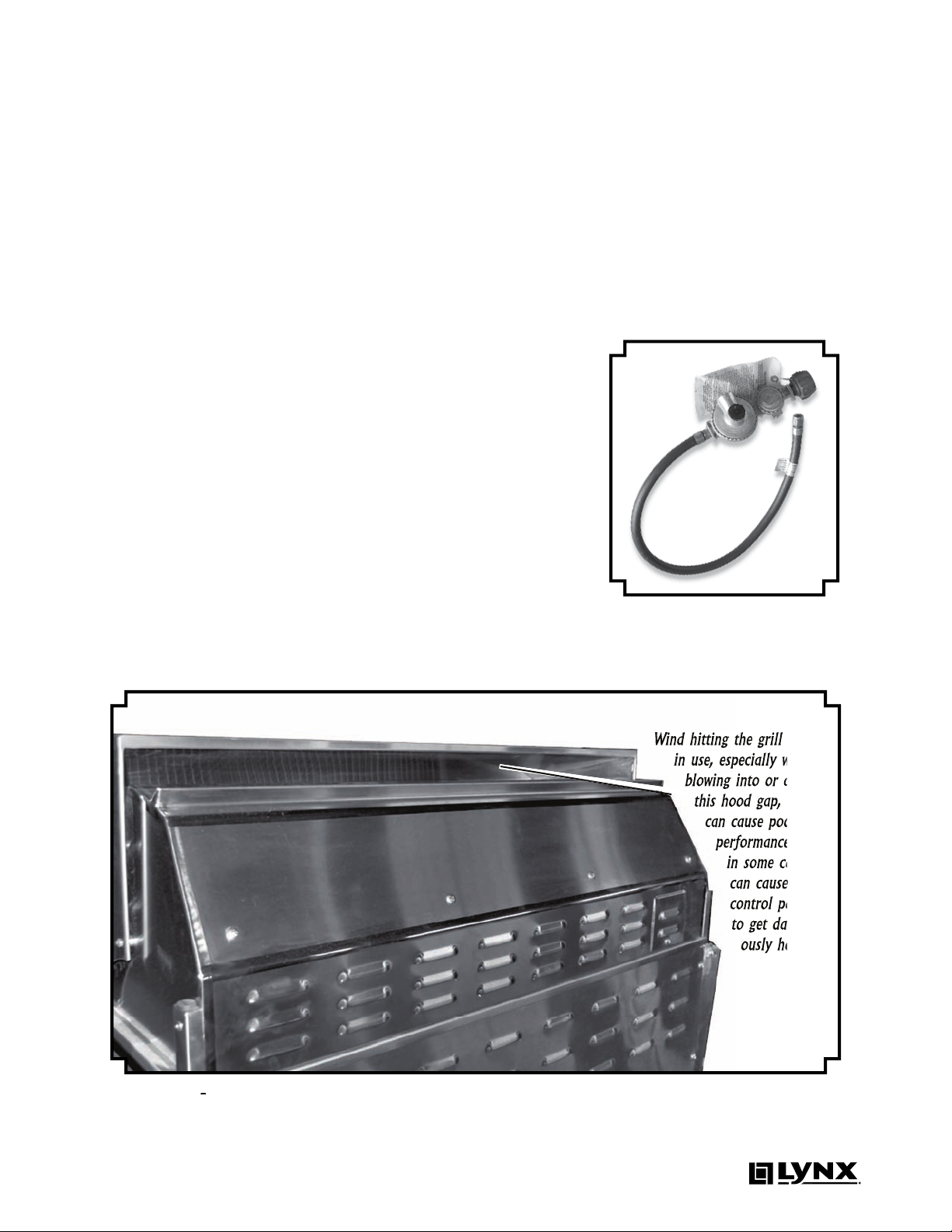
SPECIAL NOTE ON USING YOUR GRILL IN WINDY CONDITIONS
As a high-performance gas appliance, your Lynx grill requires
signicant amounts of air to support the combustion process.
Your grill has been engineered
to take air in through the control panel area, and exhaust the
combustion byproducts out
through the gap between the
front and rear hoods (see gure
3-2 at right).
Using your grill in windy conditions can disrupt the proper ow
of air through your grill, leading to reduced performance, or
in certain severe cases, causing
heat buildup in the control panel
area. This can lead to problems
such as having the control knobs
melt, or burn hazards when the
control panel surfaces become
too hot to touch.
During windy conditions, it is
best if you don’t use your grill.
If you have a freestanding grill,
it is best to position the unit so
the prevailing wind blows into
the front control panel (or at
your back), thus supporting the
proper airflow. Winds hitting
the back of the grill directly are
the most likely to cause prob-
lems, although wind blowing
along the hood gap can also be
problematic.
Please note that damage to
your grill resulting from use
in windy conditions, such
as melted knobs or igniter
wires, or control panel discoloration from heat buildup, are excluded from warranty coverage.
2
Page 7
3
in use, especially winds
performance and
in some cases
3
2
Steady or gusty winds can prevent the normal exhaust of hot gases. Locate your grill
away from prevailing winds and avoid grilling in windy conditions.
with regulator and Type 1 con-
ow until a positive connection
will restrict the ow of gas to 10
The cylinder control valve
THE PROCEDURE ON PAGE 11.
thereby shutting o the ow of
termined and corrected before
Improper lighting proce-
to activate, resulting in reduced
to reset ow control, shut o
valve, wait 30 seconds, then
turn cylinder valve on extremely
turn burner valve on to light.
3
-1 -
and regulator must be used if your
grill is set-up for an LP Gas Cylinder.
Page 8

4
When selecting a suitable loca-
tion, take into account concerns
trac paths. Try to keep all gas
A carpenter’s
front-to-back and side-to-side.
tion may be erratic or the unit
the oor is uneven or has a de-
freestanding unit.
The LYNX Built-In Grill is designed
for easy installation into mason-
tible applications, the grill drops
from its counter-top trim. A deck
the bottom. When using the in-
tisserie, electrical service should
4” clearance. The grill exhausts
will be dicult to clean.
4" min. for all other sizes
2" min. for 27" grills
Required clearance
top of unit are 12” from sides and
Dégagement minimal entre les
parois latérales et l’arrière de
l’appariel et la construction com-
supérieur de l’appareil (30 cm à
partir des parois latérales et 30 cm
à partir de l’arrière).
from sides and back of unit to
top of unit is 12” from sides and
Dégagement horizontal minimal
de l’appariel et la construction
de l’appareil (30 cm à partir des
parois latérales et 30 cm à partir
de l’arrière).
Ne pas utiliser cet appareil sous
A minimum of 6” of clearance is
for the motor and skewer.
a combustible enclosure, an
approved insulated jacket is
and is available from
your LYNX dealer.
Refer
to next page for cutout dimen-
Page 9
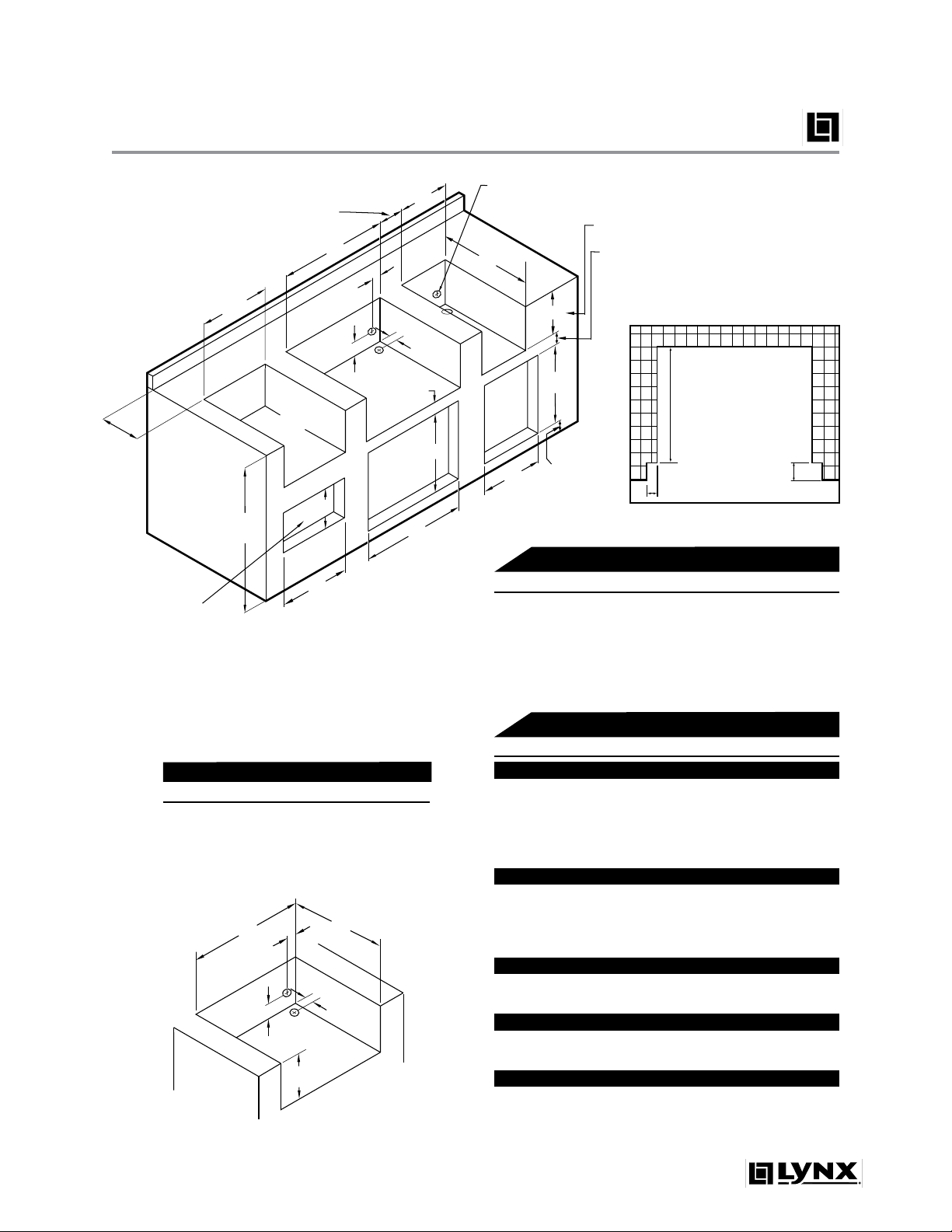
Cutout Dimensions for 2008 Built-ins
Insulated
Jacket
a
f
e
c
d
b
2" 0 or 2" square holes
for manifold connection
(rear or bottom access)
12" min.
Grill
CocktailPro*
Warming Drawer/
Convenience Center
Utility
Drawer
Side
Burner
Access
Doors
19"
A
B
D
E
G
F
H
29"
2 1/4"
4 1/2"
min.
3 1/2"
1 1/8"
min.
1 1/8" min. for model LUDE
3 1/2" min. for model LUDXL
2 1/2" min. for model LDR
3 1/4" min.
2"
10 7/8"
36 3/8"
min.
C
10 1/8" for L36 models
Dim C to cabinet face
5/8" for Grills
9/16" for Complementary Products
Depth equals
countertop
overhang
*CocktailPro should have an
open bottom for plumbing
and drain access.
Counter top Notch Detail
Specifications are subject to change without notice.
Professional Grills and ProSear Pod
Model A B C D E F G H
L27 - 26 22 - - - - L30 - 29 24 1/2 - - - - L36 - 35 22 - - - - L42 - 41 24 1/2 - - - - L54 - 53 24 1/2 - - - - -
Note: Insulated jacket required for all grills installed
into a combustible enclosure. See detail below.
With Insulated Jacket Installed
Model a b c d e f
LIJ27 33 5 24 4 1/2 3 11 5/8
LIJ30 36 5 26 1/2 4 1/2 3 11 5/8
LIJ36 42 5 24 4 1/2 3 11 5/8
LIJ42 48 5 26 1/2 4 1/2 3 11 5/8
LIJ54 60 5 26 1/2 4 1/2 3 11 5/8
Complementary Products
Model A B C D E F G H
Access Doors
LDR21-1 LDR27-1 - - - 25 1/4 - - - LDR30-1 - - - 28 1/4 - - - LDR36-2 - - - 34 1/4 - - - LDR42-1 - - - 40 1/4 - - - -
LSB1 12
LSB2 12 1/8 - 24 1/2 - - - - LSB2PC 24 1/4 - 24 1/2 - - - - LPSGE 12 1/8 - 24 1/2 - - - - -
LUDE LUDXL - - 24 1/4 - 17 1/4
L30WD L42CC - - 24 1/2 - - - 40 1/4 19 3/8
CS30 -
- - 19 1/4 - - - -
Side Burners and ProSear Grill Extender
1/8 - 24 1/2 - - - - -
Utility Drawers
- 24 - 12 1/8 19 1/4 - -
Warming Drawers
- 20 1/2 - - - 28 1/2 10
CocktailPro
- 22 3/4 - - - - -
18 9/16 - -
5
Page 10
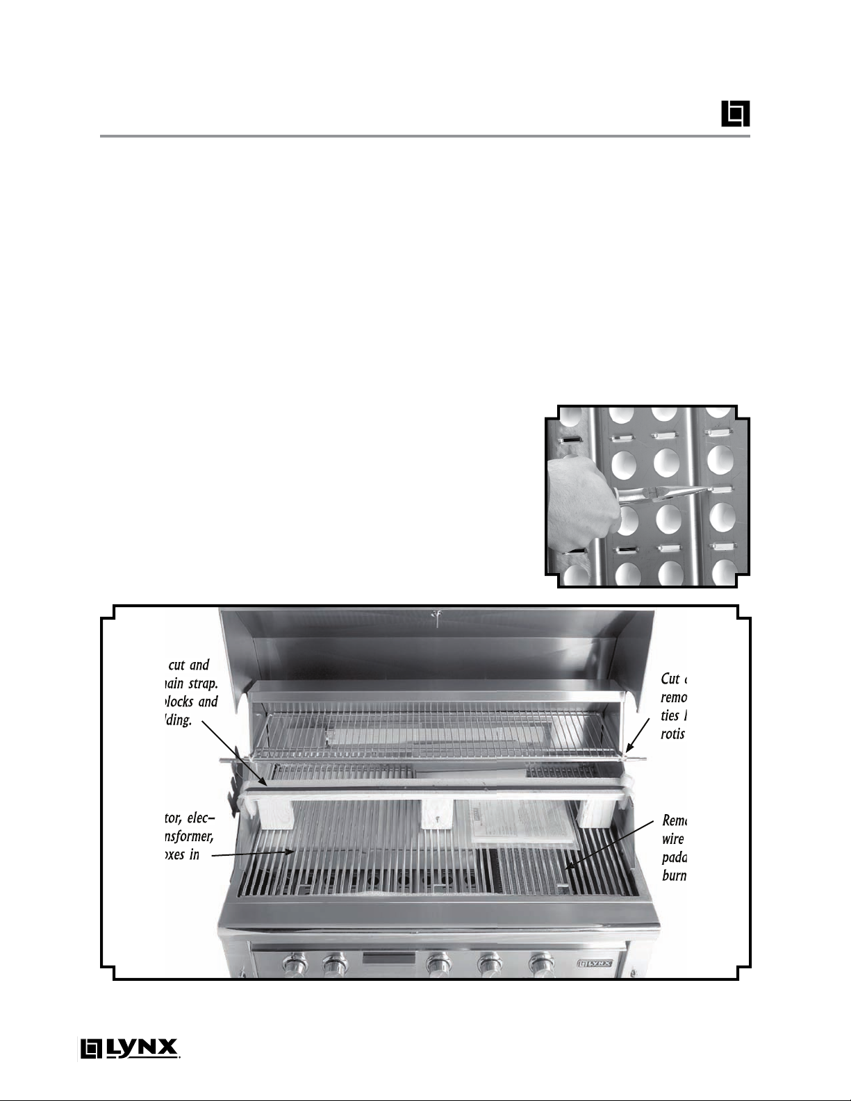
6
Your grill arrives nearly ready to
Cut the main strap holding
the grill to the pallet. With as-
Carefully cut the cable ties
Remove the grill racks, then
rebox, including the rotisserie
4)
Carefully remove the bri-
the front of the grill.
Inspect briquette trays for
found, follow procedure at right
to reinstall.
Cut and remove wire and/or
On ProSear models, cut and
Re-install grill racks.
You are now ready to proceed
with the utility connections.
TO REPLACE BRIQUETTES
The special Lynx ceramic bri-
with stainless steel clips. To in-
from one side of the empty slot.
This is done by bending the re-
taining tabs for the clip located
tray as shown below.
6
-1 -
Identication of items needing to be removed and/or assembled prior to use.
remove main strap.
foam padding.
remove cable
rotis spit.
padding from
firebox.
Page 11
WARNING
WARNING
This outdoor gas cooking appli-
the third prong from this plug.
AVERTISSEMENT
AVERTISSEMENT
Instruction pour la mise à la
de vous protéger des chocs et doit
prise de courant à trois broches adé-
quatement mise à la terre. Il ne faut
pas couper ou enlever la broche de
mise à la terre de cette che.
the island enclosure for built-in
which reduces shock hazard.
7-1 -
nection point on left rear grill
tem fails to operate, a connection
for more details.
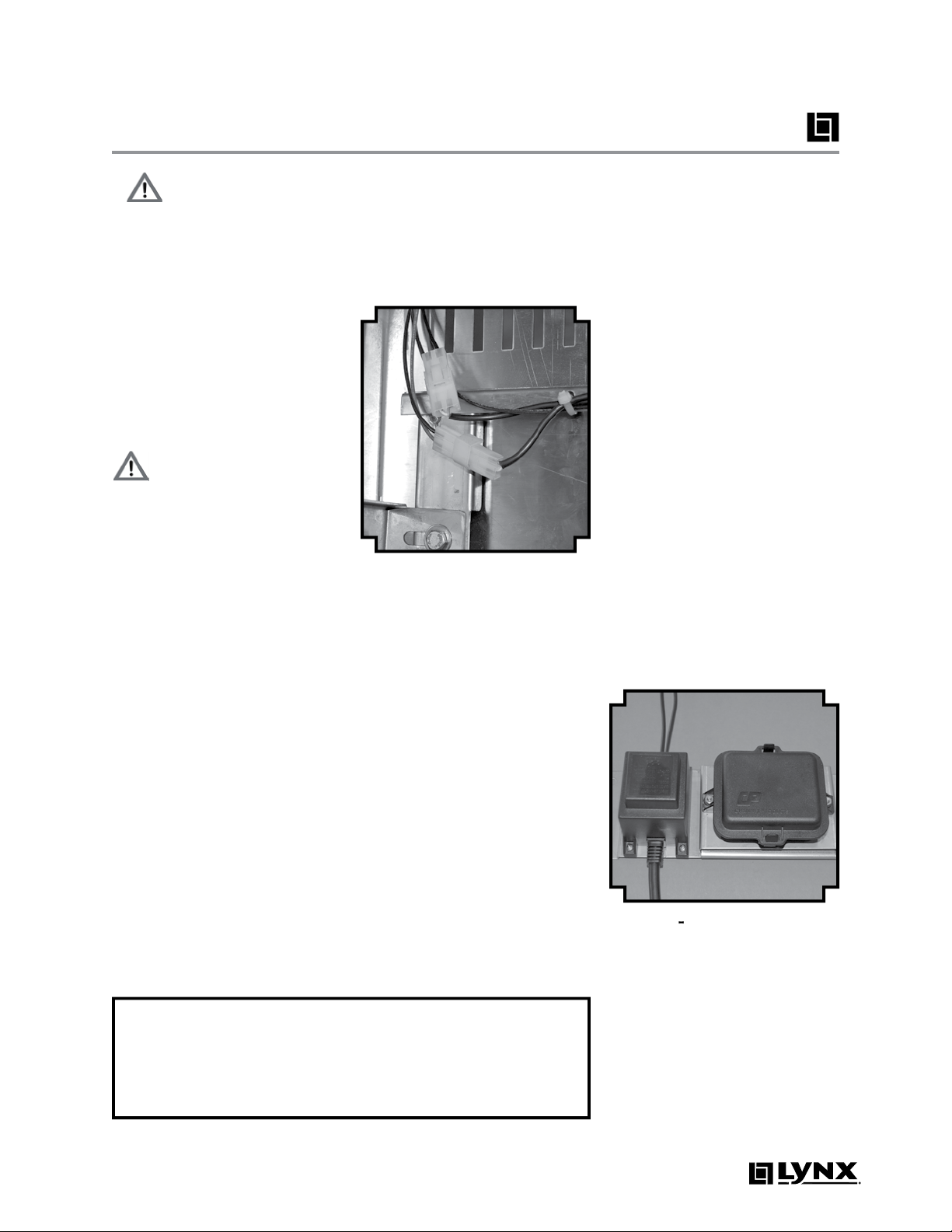
Alkaline - #E95, D size)
Your grill includes two D Cell
follow this procedure:
Locate the battery compart-
this is located inside the grill cart
the unit where the installer has
former bracket. (See gure 7-2)
Disengage the cover from the
the clips on the top and bottom
Insert 2 new D cell batteries
72 -
Locating battery
Page 12

Shut-off valve
Incoming natural
gas supply pipe
3/4” Min. Dia.
flexible connector
Convertible Regulator
supplied with grill
(Gas type conversion
requires conversion kit -
contact dealer for details)
3/4" NPT
to 3/4" flare
fitting
1/2" Male to 3/4” Female elbow
Gas Requirements & Hook-up
Your grill is setup to use either
propane (LP) or natural gas (NAT).
It is very important that the
grill rating plate matches
with your gas supply.
The rating plate is located in one
or more of the following places:
• under the drip tray
• on the heat shield behind the
front panel
• on the inside left cabinet wall
(most freestanding grills)
Do not attempt to operate the
grill on any gas other than what
the grill is oriced for and what
the regulator is set for. Should
you need to convert your grill
for use with a dierent gas type,
a conversion kit, available from
your dealer, is required.
Never connect an unregulated gas line to the grill.
so as to calculate what size diameter pipe is needed, for the total
length of pipe from the gas main
(at house) to grill hook-up. If the
gas line is too small, the grill will
not function properly. In no case
should pipe less than 3/4” inside diameter or 1” outside
diameter be used to connect
this product.
An installer-supplied gas
shut-o valve must be installed in an easily accessible location. All installer-supplied parts must
conform to local codes
with the National Electrical
Code, ANSI/NFPA 70-1990
and the National Fuel Gas
Code, ANSI Z21.58D-2002.
The appliance and its individual
shut o valve must be disconnected from the gas supply
piping system during any pres-
sure testing of that system at
test pressures above 1/2” PSIG
(3.5KPA). The appliance must
be isolated from the gas supply
piping system by closing its individual manual shut o during
any pressure testing. Do not apply threading compound to the
rst two pipe threads as to avoid
clogging of the burner valves
and orice. Do not put sealant
on any male end of are ttings.
For built-in installations, it is recommended that any exible pipe
used be kept as short as possible. For freestanding units using
natural gas, it is strongly recommended that a quick disconnect
kit from Lynx be installed. This
kit, part #LQD, is available from
your dealer.
IMPORTANT- See Gas
Plumbing Requirements
on page 28 for additional
information
NATURAL GAS
The installation of the grill must
conform with local codes or, in
the absence of local codes, to
the National Fuel Gas Code ANSI
Z21.58D-2002 or latest edition. If
installed in Canada, installation
must be in accordance with Gas
Code CAN / CGA-B149.1/.2 and
local codes.
The gas supply line must be
sized to accommodate all the
gas-red equipment that may
be connected to that supply,
i.e. total BTU output to be consumed, needs to be determined
8
Figure 8-1
Fittings shown below are for a
typical installation and are not
supplied with the grill. As each
installation may require different plumbing, Lynx recommends
that this step be performed by
a qualified technician.
- Typical attachment for using natural gas.
Page 13

L.P. GAS
Use regulator here for
hard-plumbed L.P. hookup
(LYNX P/N 30781)
L.P. hose/regulator
20 lb. Type 1 L.P. tank
3/8” flare fitting (hose ships
pre-installed on grill)
Grills oriced for use with L.P. gas
come equipped with an LP hose/
regulator assembly for connection to a standard 20 lb. L.P. cylinder (Type 1). All ttings necessary to attach the hose/regulator
to the grill are included. The L.P.
tank is not included. Operating
pressure: 11.0” W.C.
L.P. Tank Requirements
A dented or rusty L.P. tank may
be hazardous and should be
checked by your L.P. supplier.
Never use a cylinder with a damaged valve. Always check for
leaks after every L.P. tank change
(see page 11).
The L.P. gas cylinder must be
constructed and marked in accordance with the specications
for L.P. gas cylinders of the U.S.
Department of Transportation
(DOT) and designed for use with
a Type 1 system only. Do not
change the regulator/hose assembly from that supplied with
the unit or attempt to use a
5LP-A equipped regulator/hose
assembly with a standard 510
POL tank/valve assembly. The
cylinder must be provided with
a shut o valve terminating in
an L.P. gas supply cylinder valve
outlet specied, as applicable,
for connection Type 1.
Turn o LP-gas supply at cylinder
when appliance is not in use.
Fermez l’alimentation en GPL à
la bouteille si l’appareil ne fonctionne pas.
The LP-gas supply cylinder must
be disconnected when this appliance is not in use.
La bouteille de GPL doit être déconnectée si cet appareil ne fonctionne pas.
Your local L.P. lling station
should be equipped with the
proper equipment to ll your
tank. If trading your tank in,
always ensure to obtain only
Type 1 20lb cylinders with an
overll protection device.
L.P. Connections
Connect the 3/8” are end of the
L.P. hose to the brass adapter on
the manifold (as shown in gure 9-1). Connect the Regulator
to the tank (with the tank valve
fully closed). Although the ow
of gas is stopped when the Type
1 system is disconnected, you
should always turn the L.P. tank
main valve o after each use
and during transport of the tank
or unit. Insert the regulator inlet
into the tank valve and turn the
black coupler clockwise until the
coupler is tight. Do not over-
tighten the coupler.
To disconnect the coupler, rst
make sure the main tank valve
is turned o. Grasp the coupler
and turn counter clockwise. The
inlet will then disengage.
For hard plumbed LP connections to a large source (tank), a
4/11 regulator must be utilized.
Never connect an unregulated
gas line to the grill.
Gas Line Purging
To purge the L.P. gas line, make
sure all controls are in the OFF
position. Turn the main tank
valve on SLOWLY and turn one
burner control valve on the unit
to the “light” position (DO NOT
LITE GRILL). Leave control ON for
about 20 seconds to allow the
air in the system to purge. Wait
5 minutes before attempting to
light the burners.
Do not attempt lighting the grill
within 5 minutes after purging!
Cylinders must be stored
outdoors in a well-ventilated area out of the reach of
children. If the appliance
is stored indoors, the L.P.
cylinder must be removed
from the appliance, and
stored outside.
Figure 9-1
- Typical attachment to L.P. tank.
9
Page 14

10
TO REDUCE THE RISK OF
ATTENDED WHILE COOKING.
Prior to using grill ensure that
Never operate the grill in a
windy area. See page 2 for de-
tails.
4)
Avoid wearing loose-tting
your bare hands as these areas
Use an insulated glove or mitt
when opening and operating
the grill. Open grill lid slowly to
Never lean over hot grill sur-
face or look directly into the grill
when attempting to light. The
when lighting.
Do not heat unopened food
Do not use aluminum foil to
will alter combustion airow or
trap excessive heat in the control
with any type of pots and/or pans.
These damages are specically
Never use charcoal in the grill.
Be aware that cooking exces-
Never grill without the drip
Grease is extremely am-
Do not use the grill until a
Do not operate grill under
the inuence of alcohol or drugs.
If equipped, never place
If any burner does not light
turn o all gas control knobs
with hood open and wait ve (5)
this or any other grill,
from the front of the
which can cause a re to
Page 15

-
Leak testing points when using natural gas.
2
-
Leak testing points when using L.P. gas.
DANGER
To prevent re or explosion hazard, DO NOT use or
WHILE PERFORMING THE LEAK TEST!
To Perform Leak Test
Create a soapy solution of
Conrm that all control knobs
Turn on fuel supply. For natu-
to align with gas ow. For L.P.,
turn cylinder valve knob counter
4)
Apply soap solution gener-
ttings, as indicated in gures 1
If “growing” bubbles appear
then you have detected a gas
After shutting o gas sup-
turn the knobs back to o.
Wash o soapy solution with
Stop a leak by tightening
the loose joint, or by replacing
the faulty part with a replace-
to repair the L.P. cylinder valve if
4)
Perform a new leak test to en-
Page 16

1
2
Grill
42” Professional
Grill ProSear Rotis
Grill Grill
Model Identification
main grill burner found under
intensity infrared burner that
is optional on most models.
Page 17

3
through without burning the
time or foods basted with a sug-
while allowing the outer surface
to absorb smoke and food aro-
the burner. The result is a crisp,
avorful outside with a tender,
juicy inside. While the brass
Properly pre-heat the grill by
following the lighting instruc-
tions on pages 14-15.
Leaving the burners set to “HI”,
Adjust the burners to a lower
til desired doneness is reached,
turning the food as needed.
thermometer (if equipped).
Properly pre-heat the grill by
following the lighting instruc-
tions on pages 14-15.
Once grill has been preheated,
turn o any burners not required
for cooking. The lid should be
Adjust heat setting as required
to maintain desired temperature.
All internal packaging removed?
Wind is not blowing too strongly and/or hitting back of grill?
the ceramic burner. This
Page 18

1
4
WARNING
Always wait at least 5 min-
you have completed the check-
fore each use of the grill.
Open hood . Do not attempt to
Check to ensure that all burner
Turn on main gas supply.
4)
Push in and turn burner con-
trol knob to LITE. Hold knob in
for 5 seconds.
If burner does not light, turn
the grill for best results. To pre-
the ProSear burner. Close the grill
ture reaches 450°F.
After preheating, turn o all burn-
the hood, and adjust remaining
TENDED DURING THE PREHEAT
THE GRILL IS IN USE. DO NOT
ALLOW GRILL TO PREHEAT FOR
AND PERSONAL PROPERTY.
far away from the grill as pos-
the alternate lighting rod (Fig-
the burner to LITE. If the burner
the knob o and wait 5 minutes
4-1 -
Alternate
lighting rod.
The valves on the grill feature
to uctuations in gas pressure,
you may feel it necessary to ad-
just gas ow in the low position.
Light the burner.
Turn the control knob to the
ter-clockwise).
4)
While holding the valve shaft
with pliers, insert a thin at
tipped screwdriver into the shaft
2
Adjusting
knob
removed
stem
Page 19

5
The ProSear burner has some
to read this section completely
Do not light the grill until you
Ensure that burner ties and
Special care should be ex-
4)
The cooking grids are heavy.
when removing or replacing
when removing or replacing
the cooking grids.
the cooking grids.
The tiles
within the IR burner(s) will be
Open hood completely. Do
Check to ensure that all burn-
Turn on main gas supply.
4) Push in and turn burner con-
trol knob to LITE. Hold knob in
for 5 seconds.
If burner does not light, turn
The ProSear burner is ready to
Allow unit to cool completely
After each use, it is impor-
tant to operate the ProSear
the burner surface over time.
the surface of the burner. Only
there are no obstructions. If any
follow the burner cleaning pro-
turn the burner knob o
to extinguish the ame.
Wait several minutes
Page 20

Using the Rotisserie
The rotisserie system consists of
three main parts - the motor, the
skewer which holds the food,
and the infrared rotis burner. The
rotisserie evenly cooks large cuts
of meat by turning them continuously in front of a high-intensity burner. The rotis is capable of
turning up to a 25 lb. cut of meat.
THE MOTOR
The rotisserie motor runs on 12
volt DC power that is supplied
by the grill. To power the motor,
plug the “L” shaped jack of the
power cord into the motor, and
plug the other end into the jack
provided on the left side of the
grill (see gure 16-1). This hookup allows for simple installation
and removal of the motor for
storage when not in use.
THE SKEWER
To load the skewer, slide one of
the meat holders onto the skewer. Push the skewer through the
center of the food, then slide the
second meat holder onto the
skewer. Center the food to be
cooked on the skewer then push
the meat holders rmly together.
Tighten the thumb screws (use
pliers if necessary). It may also be
necessary to wrap the food with
butchers string (never use nylon
or plastic string) to secure any
loose portions.
Remove the warming rack and,
if needed, remove the grill racks
and briquette trays to gain better clearance. It is normal for the
skewer to ex when cooking
large foods. Place a basting pan
beneath the food for basting
and to ease cleaning.
Never operate a grill burner
with a basting pan in place.
Rear position - for small
foods such as game hens
Front position - for
larger cuts of meat
Side view of grill
Figure 16-2
rotisserie system.
- Dual position
THE INFRARED BURNER
The location of the rotis burner
makes it more susceptible to
strong wind conditions (more
so than the main grill burners).
For this reason you should avoid
operating the rotis during windy
conditions. As an added safety
feature, the burner is equipped
with an automatic safety valve
which will not allow gas to ow
to the rotis burner if it is not
properly lit. To light the rotis
burner, follow this procedure:
16
Figure 16-1
power jack located on grill
- Rotis motor
NOTE: The grill must be con-
nected to 115 volt AC power as
described on page 7 for the rotis
motor to function.
Install the motor onto the grill by
sliding it onto the bracket located on the left side of the grill.
The skewer for the rotis is assembled into the motor assembly
by placing the pointed end into
the motor, and resting the short,
round end (threaded end on 27”
models) onto the support at the
opposite side of the grill. With
the skewer pushed into the motor, it should rest on the bracket.
The Lynx rotisserie features dual
positions to accommodate larger cuts of meat or to allow slower cooking (see gure 16-2). Any
food to be cooked should be a
minimum of 2” from the surface
of the infrared burner.
1) Open hood completely. Do
not attempt to light grill with the
hood closed.
2) Load food onto skewer, and
install motor and skewer onto
grill in desired cooking position.
3) Check to ensure that all burn-
er control knobs are set to OFF.
4) Turn on main gas supply.
Purge if needed (see page 9).
5) Push in and turn burner con-
trol knob to LITE. Hold knob in
for 30 to 60 seconds.
6) If burner does not light, turn
knob to OFF, wait 5 minutes to
continued...
Page 21

tables will have a more tradition-
front and rear tabs rest on the
Wood Chips
There are many wood chips
water prior to putting them into
the box. Use the High position to
72 -
Smoker box
installed into grill for use.
to prevent them from drying out
ame. Use caution when adding
water to a hot box to avoid steam
with water to produce steam.
Whether smoking or steaming,
the grill should remain closed as
the eect. During extended
to the box several times. Limit
the amount of times the hood
the cooking time.
Handle the smoker
times can vary greatly by cut of
3
the control knob depressed, the
thermocouple position may
To adjust, ensure that only the
WHEN THE BURNER IS HOT.
the burner, it can be match lit ac-
Always use basting pan
Proper rotis
Page 22

18
The best way to keep your grill
Your grill has a directional pol-
The grill is made from non-rust-
After initial usage, areas
the intense heat given off by
the burners - this is normal.
There are many different stain-
Always use the mildest cleaning
faces of the stainless steel and
the appearance of rust. To aid
tion with a stainless steel cleaner.
Always rub in the direction of the
The best maintenance for stain-
true if a swimming pool is locat-
warranty. Never use steel “Brillo”
will leave traces of material
The easiest way to clean the grill
the burners. Wearing a long BBQ
AN UNLIT PROSEAR BURNER CAN
THE GRILL RACK ABOVE THE
AND REMOVE FROM GRILL.
The drip tray should be cleaned
Allow the grill to cool complete-
free. Clean with hot soapy water
TRAY PROPERLY INSTALLED.
Although they normally burn
to clean the briquette trays on
to cool completely, remove the
their mounting points, and oper-
for 20-30 minutes to burn the
the briquettes, replacements
Always keep the area
free from all combus-
tible materials, liquids,
vapors, debris and ob-
Page 23

the grill has completely
To Remove Brass Burners:
the front. Angle the burner side-
ways, and remove. Be careful not
to upset the air shutter position.
To maximize grill performance,
with a wire brush. Clear stub-
the air shutter. Use a ashlight
to inspect the burner inlet to en-
tions can be seen, use a metal
wire coat hanger that has been
version from one gas to another
the burners. The ames of the
g. 19-1. Flames should be blue
with air shutter adjustment.
9-1 -
Showing
proper ame characteristics.
height
The amount of air which enters
for adjustment (see g. 19-2).
To Adjust:
Be extremely careful as the
If the ame is yellow, indicat-
If the ame is noisy and tends
to lift away from the burner, indi-
4)
Once adjusted, turn the burn-
92 -
Air shutter set
screw location on burner
set screw
wire coat hanger that has been
TER EVERY BURNER ON
THE BURNERS TO REST
THE BURNERS ARE NOT
A VERY DANGEROUS
TO THE UNIT.
Page 24

Troubleshooting
If the Grill does not function
properly, use this checklist before
contacting Lynx for service.
GRILL WON’T LIGHT
Check to ensure that all burner
control knobs are set to OFF.
Push control knob in and ensure
that the ignition is glowing. If
ignition is not glowing, proceed with troubleshooting or
match-light the burner. If the
igniters are working correctly,
next determine if gas is reaching
the burners. Ensure the gas supply is turned on, and that there
are no leaks, according to the
procedure on page 11. Attempt
to match-light a burner according to the procedure on page
14. If the burner will light with
a match, then the igniter may
not be functioning correctly, or
may not be adjusted correctly.
See above or call for service. If
the burner will not match light,
and the gas supply has been
confirmed, check the burner for
blockages according to the procedure on page 19.
YELLOW FLAME/GAS SMELL
IF YOU SMELL GAS WHILE
THE GRILL IS OPERATING,
IMMEDIATELY TURN OFF ALL
BURNERS. Perform a leak test,
check for blockages and check
the air shutter adjustment
according to page 19.
NOTE: If the grill is operating in
a dusty area or if heavy grease
is present, some orange tips on
the burner flame are normal.
LOW/INSUFFICIENT HEAT
Ensure that adequate preheat
time has elapsed. Brass burners
should preheat for at least 15
minutes with the hood closed;
ProSear burners should preheat
for at least 3 minutes.
If adequate preheat time was
allowed, check the gas supply
for a damaged and/or kinked
supply line. Replace if necessary.
On LP units, a mostly empty tank
may not have sufficient pressure to run the grill at high heat.
Replace with a full tank. Make
sure that the regulator/hose
assembly being used is the unit
supplied with the grill. On natural gas units, ensure that the
supply line is at least 3/4” inside
diameter or 1” outside diameter.
Check the Natural Gas supply
pressure to ensure at least 7”
W.C. and 4” W.C. pressure under
full load (all burners on.) For LP,
11” W.C. supply (not to exceed
14”) with 11” under full load.
If gas supply is adequate, check
burners for blockages and check
flame characteristics according
to the procedure on page 19
and clean or adjust air shutter if
needed. Check also that there is
no pressure being applied to the
regulator attached to the back
of the grill. This regulator contains a flexible diaphragm and
should not be allowed to touch
the grill body or surroundings.
Check to make sure that the
burners and the drip tray are
clean and free from obstruc-
tions. Clean if necessary. NOTE:
No part of the grill should ever
be lined with aluminum foil as
it will interfere with airflow and
can cause a low heat condition.
BURNER BLOWS OUT
First determine if the problem
is being caused by location.
If location is subject to high
winds, reposition grill to provide
some protection. Check the gas
supply and flame characteristic according to the procedure
under Low/Insufficient Heat.
Check to ensure that the burners
are correctly positioned in the
grill according to the procedure
on page 19. Correctly installed
burners should be seated firmly
with no side-to-side movement.
ROTISSERIE WON’T LIGHT
Follow the same procedure as
described above for the grill
burners to diagnose problems
with the Rotisserie IR burner. The
IR burner flame may be hard to
see in bright sunny conditions.
LIGHTS WON’T OPERATE
Ensure that the grill has AC
power by removing the D cell
battery according to the instructions on page 7, and then pressing a burner control knob to test
the spark igniter. If the igniters don’t function, no AC power
is connected. If the igniters do
function, replace the bulb.
20
Page 25

Light Bulb Replacement
TO CHANGE LIGHT BULBS
Remove the glass light cover by
grasping the edge of the glass
and gently prying it o. It may
be necessary to remove one
screw. Pull the old bulb straight
out from socket - do not twist.
Replacement bulbs are halogen,
12 volt, T3 type with a G4 bipin
base. The 27” and 30” grill uses
one 10W bulb, all others use two
10W bulbs.
AVOID TOUCHING THE
GLASS OF NEW BULBS.
Install new bulb by gently pressing it into the socket. Replace
glass cover by gently snapping
back into place.
Figure 21-1
- Remove glass cover to access work light bulb.
Replacing the Briquettes
TO REPLACE BRIQUETTES
The special Lynx ceramic briquettes are secured to the trays
with stainless steel clips. To insert a briquette into the tray, it
is necessary to remove the clip
from one side of the empty slot.
This is done by bending the retaining tabs for the clip located
on the back side of the briquette
tray as shown below.
WA R N I N G
The edges of the clips
may be sharp. Pliers
MUST be used to remove
clips - never attempt to
remove them by hand as
injury may result.
21
Page 26

Side Burner/LPSGE Gas Hookup
High pressure flexible
hose & regulator existing
on grill
1/2” FIP x 3/8” MIP Flare
Elbow or 1/2” FIP or 1/2”
FIP x 3/8” MIP Flare
Fitting
Use regulator here for
hard-plumbed L.P. hook-up
(Lynx P/N 30781)
1/2” Close Nipple
1/2” Close Nipple
1/2” MIP Fitting
1/2” Union (Coupler)
1/2” Male-Female
Street Elbow
1/2” Male-Female
Street Elbow
Side Burner or
Grill Extender
Side Burner
Manifold
BBQ Manifold
1/2” O.D. Stainless
Steel Flexible Hose
1/2” FIP Fitting
1/2” Tee
REAR VIEW
TOP
Flex Hose
Approx. 20º
from Horizontal
TOP VIEW
GRILL
N.G. Outlet Shuf-Off
Valve 1/2” Min
Inter Connecting
Pipe Work
Regulator
1/2” Close Nipple
1/2” Close Nipple
1/2” MIP Fitting
1/2” Union (Coupler)
1/2” Male-Female
Street Elbow
Side Burner or
Grill Extender
BBQ Manifold
Side Burner
Manifold
1/2” O.D. Stainless
Steel Flexible Hose
1/2” FIP Fitting
1/2” Tee
REAR VIEW
TOP
Flex Hose
Approx. 20º
from Horizontal
GRILL
BUILT-IN INSTALLATION
1)
Shut o gas supply at main
valve.
2) Disconnect all plumbing (if al-
ready attached) from grill and
gas supply valve.
3) Remove all ttings from grill
manifold.
4) Install side burner into cutout
in counter top.
5) Connect gas supply to grill
and side burner as shown in
the gure at right for your
proper gas type.
6) Turn gas supply on and leak
test all connections.
CART INSTALLATION
Natural Gas
1)
Shut o gas supply at main
valve.
2) Disconnect all plumbing (if al-
ready attached) from grill and
gas supply valve.
3) Remove all ttings from grill
manifold.
4) Install side burner onto cart
according to the directions
supplied with the cart mounting kit.
5) Connect gas supply to grill
and side burner as shown in
the gure at right for your
proper gas type.
6) Turn gas supply on and leak
test all connections.
LP Gas
22
Page 27

Lighting the Side Burner or LPSGE
WA R N I N G
Never attempt to light
burner if odor of gas
is present. Lid must be
open/o when lighting.
Keep face and body as
far from unit as possible
when lighting. Always
wait at least 5 minutes
before attempting to relight a hot burner.
Before proceeding, make sure
you have completed a leak test.
This check should be performed
before each use of the side burner or grill extender.
Follow these steps to light the
burners:
1) Open or remove lid complete-
ly. Do not attempt to light burners with the lid closed.
2) Check to ensure that all burn-
er control knobs are set to OFF.
Push control knob in and ensure
that the ignition is glowing. If
ignition is not glowing, proceed
with troubleshooting or matchlight the burner.
3) Turn on main gas supply.
Purge if needed (see page 9).
4) Push in and turn burner con-
trol knob to LITE. Hold knob in
for 5 seconds.
5) If burner does not light, turn
knob to OFF, wait 5 minutes to
allow gas to dissipate, and repeat step 4 above.
PREHEATING THE LPSGE
Before cooking, always preheat
the ProSear burner for best results. To preheat, light the burner, set to HIGH and allow to preheat until the burner glows red,
usually about 2-3 minutes.
DO NOT LEAVE THE UNIT
UNATTENDED DURING
THE PREHEAT CYCLE OR AT
ANY TIME WHILE IN USE.
DO NOT ALLOW UNIT TO
PREHEAT FOR PROLONGED
PERIODS OF TIME. OVERHEATING THE UNIT CAN
CAUSE DAMAGE TO THE
UNIT AND TO PERSONAL
PROPERTY.
MATCH LIGHTING
If burners will not light after several attempts, the burners can be
match lit. If you’ve just attempted to light the burner with the
igniter, allow 5 minutes for any
accumulated gas to dissipate.
Make sure all knobs are in the
OFF position. Keep your face as
far away from the unit as possible. With the lid removed, pass
the alternate lighting rod with a
lit paper match installed to the
ports of the burner. Push and
turn the corresponding control
knob of the burner to LITE. If the
burner does not light in 4 seconds, turn the knob o and wait
5 minutes before attempting
again.
LOW HEAT ADJUSTMENT
NOTE: ADJUSTMENT IS
FOR SIDE BURNERS ONLY.
PROSEAR BURNERS ARE
PRESET AT THE FACTORY
AND SHOULD NOT BE ADJUSTED.
The valves on the side burner
feature an adjustable low setting. Due to uctuations in gas
pressure, heating value or gas
conversion, you may feel it necessary to adjust gas ow in the
low position.
1) Light the burner.
2) Turn the control knob to the
lowest setting (all the way counter-clockwise).
3) Remove the knob.
4) While holding the valve shaft
with pliers, insert a thin at
tipped screwdriver into the shaft
and while viewing the burner,
adjust to a minimum stable
ame (see gure 23-1).
knob
removed
valve
stem
Figure 23-1
side burner low heat setting.
- Adjusting
23
Page 28

Warranty
I. Limited Lifetime Warranty. The stainless steel body housings, the solid brass grill burners and the ProSear burners* are warranted to be free from defects in material and workmanship when subjected to normal domestic use
and service for the lifetime of the original purchaser. This warranty excludes surface corrosion, scratches, and discoloration which may occur during regular use. This warranty is limited to the replacement of the defective parts, with
the owner paying all other cost including labor. *Does not include the rotisserie infra-red burner.
II. Limited Five-Year Warranty. The structural integrity of the interior grill parts, exterior, and drip pans are warranted to be free from defects in material and workmanship, when subjected to normal domestic use and service, for
a period of five years from the date of purchase. This warranty is limited to the replacement of the defective parts,
with the owner paying all other cost including labor.
III. Limited One-Year Warranty. All other grill components are warranted to be free from defects in material and
workmanship for a period of one year from the original date of purchase. Lynx will replace or repair parts found to
be defective at no cost to the original purchaser.
IV. Limitations & Exclusions
1) Warranty applies only to the original purchaser and may not be transferred.
2) Warranty is in lieu of all other warranties, expressed or implied and all other obligations or liabilities related to the
sale or use of its grill products.
3) Warranty shall not apply and Lynx is not responsible for damage resulting from misuse, abuse, alteration of or
tampering with the appliance, accident, hostile environment, flare-up fires, improper installation, or installation not
in accordance with the instructions contained in this manual, or the local codes.
4) Lynx shall not be liable for incidental, consequential, special or contingent damages resulting from its breach
of this written warranty or any implied warranty.
5) Some states do not allow limitations on how long an implied warranty lasts, or the exclusions of or limitations
on consequential damages. This warranty gives you specific legal rights and you may have other rights which
vary from state to state.
6) No one has the authority to add to or vary Lynx’s warranty, or to create for Lynx any other obligation or liability in connection with the sale or use of its products.
7) Limited to the replacement of defective parts with the owner paying all other costs including labor.
V. What is not covered. Lynx shall not be responsible for and shall not pay for the following:
1) Installation or start-up, damages or problems caused by improper installation or use;
2) Service by an unauthorized service provider;
3) Damage or repair due to service by an unauthorized service provider or use of unauthorized parts;
4) Units installed in non-residential applications such as day-care centers, bed and breakfast centers, churches,
nursing homes, restaurants, hotels, schools, etc.;
5) To correct normal adjustments or settings, due to improper installation, commissioning or local gas supply
properties;
6) Shipping and handling costs, export duties, installation, removal, or re-installation cost;
7) Display models are generally sold “as is.” If you have purchased a display model, please be advised that it is
sold “as is” and that it is subject to the following warranty exclusions: any exterior or cosmetic damage is nonwarrantable; any missing components will be replaced at consumers expense; major handling damage to manifold, valve and ignition system will be serviced at consumer’s expense; all other warranty’s (standard warranty)
will remain in effect.
8) The cost of a service call to diagnose trouble.
See following page for information on how to obtain warranty service.
24
Page 29

How to Obtain Service
Before you call for service:
1) Is there Gas Supplied to the Grill?
2) Is there a power outage in the area (lights will not work)?
3) Have you recently refilled the LP Tank?
Before calling for service, please make sure you have the following information:
1) Model number
2) Date of purchase
3) Proof of purchase by the original owner
4) Serial number. The serial number can be located on the rating plate, which is located either
under the drip tray, on the heat shield behind the front panel, or on the inside left cabinet wall
(for most freestanding grills).
For warranty service, contact the LYNX Customer Service Department for an authorized service
agent near you. Our number is (888) Buy-Lynx (888-289-5969). Provide the Model Number, Serial
Number, date of installation, and a brief description of the problem.
Your satisfaction is of the utmost importance to us. If a problem cannot be resolved to your satisfaction, please write, fax or email us:
Lynx Professional Grills
6023-25 Bandini Blvd., Commerce, CA 90040
Service: (888) Buy-Lynx (888-289-5969)
Tel: (323) 838-1770
Fax: (323) 838-1778
www.lynxgrills.com
Contact Lynx as well for replacement parts. Parts are shipped F.O.B. Commerce, CA.
IF SHIPMENT ARRIVES DAMAGED:
1) VISIBLE LOSS OR DAMAGE: Be certain this is noted on freight bill or express receipt and
signed by person making delivery.
2) FILE CLAIM FOR DAMAGES IMMEDIATELY, regardless of extent of damage.
3) CONCEALED LOSS OR DAMAGE: If damage is unnoticed until merchandise is unpacked,
notify transportation company or carrier immediately and file “concealed damage” claim with
them. This should be done within (15) days of date delivery is made to you. Be sure to retain
container for inspection. We cannot assume responsibility for damage or loss incurred in
transit.
4) Limited to the replacement of defective parts with the owner paying all other costs including labor.
25
Page 30

Wiring Diagrams
a
c
b
d
1
2
x xx x
x x
To Halogen Light Inside Grill
Transformer
12V
Female
Jack
Valve Switches
9V Battery
IR Switch (27R Only)
Ground to
Bullnose
bracket when using
pin “D”
Thermocoupler
To Igniter Pin“d”
To Igniter Pin“c”
To Igniter Pin“a”
27R Only
Light Switch
Ignitor
x x
x x
Converter /
Back-up
Module
Battery Holder 1821-25
Valve Switches
INSP ###
x x
Glow Plugs
IR Valve
IR Plug
To
Transformer
2
1
Dome Light
Inside Grill
Insulated
wire to
Lamp
Side Burner connector
for LED’s
To Transformer
Power in for Lights
2 3
1
2
3
3
2
1
2
3
1
3
Shrink
Tubing
Light Switch
Power in - To
Rotisserie
180 _
resistor
1
2
1
2
1
2
1
2
1
2
1
2
1
2
1
2
For L27 Grills
Diagram Key
Orange Wires to Igniters
Red Wires
Black Wires
Insulated Wire to Lamp
26
For L30 Grills
Diagram Key
Orange Wires to Igniters
Red Wires
Black Wires
Yellow Wires
Green Wires
Page 31

x x
x x
Converter /
Back-up
Module
Battery Holder 1821-25
Valve Switches
INSP ###
x x
Glow Plugs
IR Valve
IR Plug
To
Transformer
2
1
Dome Light
Inside Grill
Insulated
wire to
Lamp
Side Burner connector
for LED’s
To Transformer
Power in for Lights
2 3
1
2
3
3
2
1
2
3
1
3
Shrink
Tubing
Light Switch
Power in - To
Rotisserie
180 _
resistor
1
2
1
2
1
2
1
2
1
2
1
2
1
2
1
2
INSP ###
x x
Valve Switches
Glow Plugs
IR Valve
IR
Plug
x x
x x
x x
x x
x x
IR
Plug
IR Valve
2
1
Dome Lights Inside Grill
3
1
2
3
3
2
1
To
Transformer
Insulated wire to Lamp
Side Burner connector for
LED’s
2
2
180 _
resistor
3
1
3
LED’s
Shrink
Tubing
Light Switch
Shrink
Tubing
180 _
resistor
Power in - To
Rotisserie
Battery Holder 1821-25
1
2
1
2
1
2
1
2
1
2
1
2
1
2
1
2
Converter /
Back-up
Module
To Transformer
Power in for Lights
Wiring Diagrams
For L36 & L42 Grills
Diagram Key
Orange Wires to Igniters
Red Wires
Black Wires
Yellow Wires
Green Wires
For L54 Grills
Diagram Key
Orange Wires to Igniters
Red Wires
Black Wires
Yellow Wires
Green Wires
27
Page 32

Gas Plumbing Requirements
• A pressure regulator must be installed on all gas equipment. All local codes require that
a pressure regulator be installed. Removing or failing to install the pressure regulator can
result in fire and serious bodily harm.
• An installer supplied gas shut-off valve must be installed in an easily accessible location for
all hard-plumbed natural gas and liquid propane applications.
• In order for a Lynx Grill to perform properly you must have adequate gas plumbing. Please
see the guidelines below to help ensure that you have the appropriate gas plumbing with
respect to gas pipe diameter, length of pipe run and the grills BTU requirements.
Internal Pipe
Diameter 10 ft. 20 ft. 30 ft. 40 ft. 50 ft. 60 ft. 70 ft. 80 ft.
1/2” 170,000 BTU 118,000 BTU 95,000 BTU 80,000 BTU 71,000 BTU 64,000 BTU 60,000 BTU 55,000 BTU
3/4” 360,000 BTU 245,000 BTU 198,000 BTU 169,000 BTU 150,000 BTU 135,000 BTU 123,000 BTU 115,000 BTU
Lynx Grill BTU Requirements
Grill Model Main Burners Rotisserie Burners Total
L27 50,000 BTU 15,000 BTU 65,000 BTU
L30 50,000 BTU 15,000 BTU 65,000 BTU
L36 75,000 BTU 15,000 BTU 90,000 BTU
L42 75,000 BTU 16,000 BTU 91,000 BTU
L54 100,000 BTU 30,000 BTU 130,000 BTU
Water Column Requirements
Natural Gas Supply pressure = 7” water column (17.8 cm) min. and
pressure under full load = 4” water column (10.2 cm) minimum.
Liquid Propane Supply Pressure = 11-14” water column (27.9 – 35.5 cm), not to exceed 14” water column and
pressure = 11” water column (27.0 cm) minimum.
Note: All BTU and water column requirements are approximations.
28
Page 33

Parts Diagram
29
Page 34

Parts List
30
Page 35

Page 36

Lynx Professional Grills • 6023 E. Bandini Blvd. • Commerce, CA 90040 • (888) 879-2322
years were manufacturing top-of-the-line stainless
their own.
These original commercial products are found in
York • MGM Grand • Treasure Island • Mirage • Paris
The Lynx Story…
*,"--" Ê,-
 Loading...