

Page 1

LYNXTechnik AG
Broadcast Television Equipment
© 2012 LYNX Technik AG all rights reserved
®
Reference Manual
D VD 5830
Triple 3GBit/s Dual SDI/ASI Distribution Amplifier
Revision 1.0
April 2012
This Manual Supports Device Revisions:
D VD 5830 Firmware Revision 494
Control System GUI Release 6.0.0
Information in this document is subject to change without notice. No part of this document may be reproduced or
transmitted in any form or by any means, electronic or mechanical for any purpose, without express written permission of
LYNX Technik AG.
LYNX Technik AG may have patents, patent applications, trademarks, copyrights or other intellectual property rights
covering the subject matter in this document. Except as expressly written by LYNX Technik AG, the furnishing of this
document does not give you any license to patents, trademarks, copyrights or other intellectual property of LYNX Technik
AG or any of its affiliates.
LYNX Technik AG
Brunnenweg 3
D 64331 Weiterstadt
Germany
www.lynx-technik.com
Page 2

D VD 5830 Reference Manual. Rev 1.0
Page 2 of 17
Contents
CONTENTS .......................................... ..................... ..................... ...................... .............. 2
WARRANTY ......... ............... .............. ................ ............... ............... ............... ................ .... 3
REGULATORY INFORMATION ........................................................................................ 4
E
UROPE ..................................... .................. ................ ................... ................ ................. 4
USA ................................................................................................................................ . 4
GETTING STARTED ...... ................................... ................................... .............................. 5
P
ACKAGING ........................................ ........................................ ..................................... . 5
ESD
WARNING ................................................................................................................. 5
Preventing ESD Damage ................................ .............................. .......................... .... 5
PRODUCT DESCRIPTION ............... ........ ......... ........ ......... ........ ......... ........ ........ ........ ...... 6
F
UNCTIONAL DIAGRAM ...................................................................................................... 6
M
ODULE LAYOUT .............................................................................................................. 7
CONNECTIONS ................................................ ............. .............. ................ ............. ......... 8
INSTALLATION .................................................................................................................. 8
SETTINGS AND CONTROL .............................................................................................. 9
S
WITCH SETTINGS .......................................................................................................... 10
Switch Function Detail .......................... .................................................................. .. 10
Factory Preset Condition ........ .................................................................................. 11
Auto Store ..................................................................................................... ............ 11
ALARM/LED STATUS INDICATORS ................... .......................................................... 12
Channel Condition Indicators LED 1, 2 and 3 .............. ............................. ............... 12
Alarm Indicator ................................ ................................................................... ....... 12
Local/remote LED ......... .. ...... .. ... ..... ... ..... ... ... ..... ... ..... ... .. ...... .. ...... .. ... ..... ... ..... ... ... .... 12
Power Indication ....................................................................................................... 12
CONTROL SYSTEM GUI .......................... ..... ... ... ..... ... .. ...... .. ...... .. ... ..... ... ... ..... ... ..... ... .. .. 13
Main Tab ......... ... ... ..... ... ..... ... .. ...... .. ...... .. ...... .. ... ..... ... ..... ... ..... ... ... ..... ... ..... ... .. ...... .. .. 14
Events Tab ................................. ............................................................................... 15
SPECIFICATIONS ............................................................................................................ 16
SERVICE .............................................. ................ .................. ................ ................... ....... 17
Parts List ....................................... .................................................................. .......... 17
Technical Support ..................................................................................................... 17
Contact Information................................................................................................... 17
Page 3

D VD 5830 Reference Manual. Rev 1.0
Page 3 of 17
Warranty
LYNX Technik AG warrants that the product will be free from defects in materials
and workmanship for a period of three (3) years from the date of shipment. If this
product proves defective during the warranty period, LYNX Technik AG at its
option will either repair the defective product without charge for parts and labor,
or will provide a replacement in exchange for the defective product.
In order to obtain service under this warranty, customer must notify LYNX
Technik of the defect before expiration of the warranty period and make suitable
arrangements for the performance of service. Customer shall be responsible for
packaging and shipping the defective product to the service center designated by
LYNX Technik, with shipping charges prepaid. LYNX Technik shall pay for the
return of the product to the customer if the shipment is within the country which
the LYNX Technik service center is located. Customer shall be responsible for
payment of all shipping charges, duties, taxes and any other charges for
products returned to any other locations.
This warranty shall not apply to any defect, failure, or damage caused by
improper use or improper or inadequate maintenance and care. LYNX Technik
shall not be obligated to furnish service under this warranty a) to repair damage
resulting from attempts by personnel other than LYNX Technik representatives to
install, repair or service the product; b) to repair damage resulting from improper
use or connection to incompatible equipment; c) to repair any damage or
malfunction caused by the use of non LYNX Technik supplies; or d) to service a
product which has been modified or integrated with other products when the
effect of such modification or integration increases the time or difficulty servicing
the product.
THIS WARRANTY IS GIVEN BY LYN X TE CHNIK WITH RESPECT TO THIS
PRODUCT IN LIEU OF ANY OTHER WARRANTIES, EXPRESS OR IMPLIED.
LYNX TECHNIK AND ITS VENDORS DISCLAIM ANY IMPLIED WARRANTIES
OF MERCHANTABILITY OR FITNESS FOR A PARTICULAR PURPOSE. LYNX
TECHNIK`S RESPONISIBILITY TO REPAIR AND REPLACE DEFECTIVE
PRODUCTS IS THE SOLE AND EXCLUSIVE REMEDY PROVIDED TO THE
CUSTOMER FOR BREACH OF THIS WARRANTY. LYNX TECHNIK AND ITS
VENDORS WILL NOT BE LIABLE FOR ANY INDIRECT, SPECIAL,
INCIDENTIAL, OR CONSEQUENTIAL DAMAGES IRRESPECTIVE OF
WHETHER LYNX TECHNIK OR THE VENDOR HAS ADVANCE NOTICE OF
THE POSSIBILITY OF SUCH DAMAGES.
Page 4

D VD 5830 Reference Manual. Rev 1.0
Page 4 of 17
Regulatory information
Europe
Declaration of Conformity
USA
FCC 47 Part 15
This device complies with part 15 of the FCC Rules. Operation is subject to the following
two conditions: (1) This device may not cause harmful interference, and (2) this device
must accept any interference received, including interference that may cause undesired
operation.
Note: This equipment has been tested and found to comply with the limits for a Class A
digital device, pursuant to the part 15 of the FCC Rules. T hese limits are designed to
provide reasonable protection against harmful interference when the equipment is
operated in a commercial environment. This equipment generates, uses, and can radiate
radio frequency energy and, if not installed and used in accordance with the instruction
manual, may cause harmful interference to radio communications. Operation of this
equipment in a residential area is likely to cause harmful interference in which case the
user will be required to correct the interference at his own expense
We LYNX Technik AG
Brunnenweg 3
D-64331 Weiterstadt
Germany
Declare under our sole responsibility that the product
TYPE: D VD 5830
To which this declaration relates is in conformity with the following
standards (environments E1-E 3 ):
EN 55103-1 /1996
EN 55103-2 /1996
EN 60950 /2001
Following the provisions of 89 /336/EEC and 73/23/EEC directives.
Winfried Deckelmann
Weiterstadt, April 2012
Place and date of issue Legal Signature
Page 5

D VD 5830 Reference Manual. Rev 1.0
Page 5 of 17
Getting Started
Most CardModules are installed into the rack frames and system tested in the factory. If
this is an upgrade part, or service exchange item then the module is supplied in a padded
cardboard carton which includes the CardModule, rear connection plate and mounting
screws.
Packaging
The shipping carton and packaging materials provide protection for the module during
transit. Please retain the shipping cartons in case subsequent shipping o f the product
becomes necessary. Do not remove the module from its protective static bag unless
observing adequate ESD precautions. Please see below.
ESD Warning
This product is static sensitive. Please use caution and use preventative measures to
prevent static discharge or damage could result to module.
Preventing ESD Damage
Electrostatic discharge (ESD) damage occurs when electronic assemblies or the
components are improperly handled and can result in complete or intermittent failure.
Do not handle the module unless using an ESD-preventative wrist strap and ensure that
it makes good skin contact. Connect the strap to any solid grounding source such as any
exposed metal on the rack chassis or any other unpainted metal surface.
Caution
Periodically check the resistance value of the antistatic strap. The measurement should
be between 1 and 10 Megohms.
Page 6
D VD 5830 Reference Manual. Rev 1.0
Page 6 of 17
Product Description
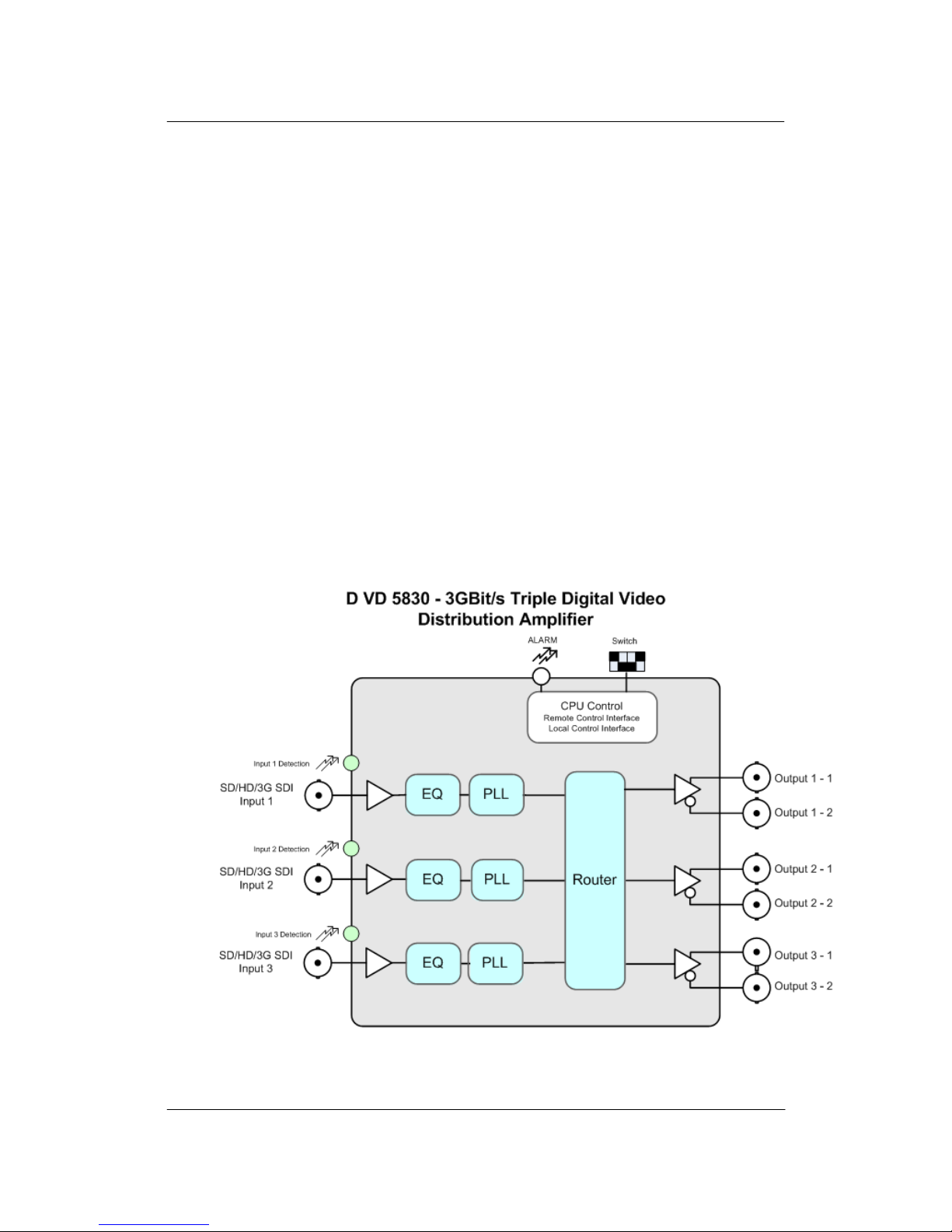
The D VD 5830 is a high quality triple channel 3GBit/s / HD / SD SDI/ASI distribution
amplifier designed primarily for broadcast and professional applications.
Flexible configurations allow the D VD 5830 to be used in dual 1 to 4 applications or 1 to
8 applications. Inputs can be reclocked, or non-reclocked. Auto detection of multirate
digital video bit rates in reclocked mode (143Mbit/s, 177Mbit/s, 270Mbit/s, 360Mbit/s,
1.485 GBit/s, 2.985GBit/s) and will transparently pass data from 15 Mbits/s to 2.985 GBit
Mbits/s in non-reclocked mode.
All outputs are ASI compatible.
Note: To ensure high signal quality the SDI receivers are located on the connection plate.
The D VD 5830 is part of the 5000 series of CardModules, which offer high quality,
modularity and flexibility in a small form factor ideal for applications where space is at a
premium.
Functional Diagram
Page 7

D VD 5830 Reference Manual. Rev 1.0
Page 7 of 17
Module Layout
Module Front Termination Panel
CardModule
Page 8

D VD 5830 Reference Manual. Rev 1.0
Page 8 of 17
Connections
Video
The D VD 5830 uses standard 75 Ohm BNC connectors. We recommend the use of high
quality video cable for digital video connections to reduce the risk of errors due to
excessive cable attenuation. Max cable lengths the modu le will support are shown below.
SDTV = 250m Belden 8281 (270Mbits/s)
HDTV = 140m Belden 1694A (1.485Gbits/s)
3GBit/s = 80m Belden 1694A (2.97Gbits/s)
Note. Due to the compact design of the connection plate it will be necessary to
use a connection tool to secure the BNC video connectors.
Installation
If this module was supplied as part of a system it is already installed in the rack
enclosure. If the module was supplied as a field upgrade please follow the installation
procedure below.
NOTE Observe static precautions when handling card. Please see ESD
warnings on Page 5.
Each Card Module is supplied with a rear connection panel and two mounting screws.
Please follow the following procedure for installation of the card module into the Series
5000 Card Frame.
1. Select a slot in the card frame where the CardModule will be located.
2. Remove the blank connection panel from the rear of the rack (if fitted)
3. Install the rear connection panel using the screws supplied. Do not tighten the
screws fully
4. Slide the card module into the card frame and carefully check the CardModule
connects to the rear connection plate. The card should fit easily and should not
require excessive force to insert, if you feel any resistance, there could be
something wrong with the rear connection panel location. Do not try and force the
connection this may damage the connectors. Remove the rear connection panel
and check alignment with the CardModule.
5. Insert and remove the CardModule a few times to ensure correct alignment and
then tighten the two screws to secure the rear connection plate.
Unused BNC inputs and BNC outputs should be terminated with
75Ohm to avoid any RF interference in between the channels
Page 9

D VD 5830 Reference Manual. Rev 1.0
Page 9 of 17
Settings and Control
The D VD 5830 has an integrated micro-controller, which enables the module to be
configured and controlled locally via the dip-switch or from remote when using one of the
optional controllers and control software.
Once set, all settings are automatically saved in non-volatile internal memory. (Flash
ram) The module will always recall the settings used prior to power down.
Page 10

D VD 5830 Reference Manual. Rev 1.0
Page 10 of 17
Switch Settings
Below the switch settings for the 8-position dip-switch are defined.
Switch Function Detail
Dip Switch 1
This switch is used to enable or disable local adjustments. Set to ON enables the setting
of the other dip switches to configure the module. Set to OFF will prevent any switch
settings taking effect.
Note. The module has a microcontroller and flash ram. When this switch 1 is set to ON
any configuration settings made on the module with the dip switches will automatically be
written into flash ram and stored. (see Auto Store) The module will function normally with
the switch left in the ON position but it is recommended to set it to OFF to prevent
accidental changes to the stored module configuration if the switches are moved.
Dip Switch 2,3 and 4
This switch configures channels be reclocked or non reclocked. ON sets reclocked, OFF
sets non-reclocked
Dip Switch 5, 6 and 7
Not used
Dip Switch 8
This switch configures the slew rate for the outputs if in non-reclocked mode. Set to
SLOW (OFF) for SD signals, set to FAST (ON) for HD or 3GBIt/s signals
Swit
ch
Setting Function
1
ON Enable Local Adjustment
OFF Disable Local Adjustment
2
ON Output 1 reclocked
OFF Output 1 non-reclocked
3
ON Output 2 reclocked
OFF Output 2 non-reclocked
4
ON Output 3 reclocked
OFF Output 3 non-reclocked
5
ON
OFF
6
ON
OFF
7
ON
OFF
6
ON Outputs: Fast Slew Rate in non-reclocked mode
OFF Outputs: Slow Slew Rate in non-reclocked mode
Page 11

D VD 5830 Reference Manual. Rev 1.0
Page 11 of 17
Factory Preset Condition
The D VD 5830 is delivered programmed and preset for the following mode of operation:
Switch 1 ON Local Adjustment Enabled
Switch 2 -4 ON reclocked
Switch 8 ON FAST
If this is the mode of operation required, then no adjustments are necessary.
Auto Store
If no parameters are changed for 10 seconds then the current settings will be written into
flash memory automatically, this can be seen by the channel status LEDS flashing yellow
four times.
Page 12

D VD 5830 Reference Manual. Rev 1.0
Page 12 of 17
Alarm/LED Status Indicators
The D VD 5830 module has integral LED indicators, which serve as alarm and status
indication for the module. Function is described below.
Channel Condition Indicators LED 1, 2 and 3
3 status LEDs are provided to indicate the status of the SDI inputs,
Alarm Indicator
There is also a single alarm LED on the lower edge of the module.
This is visible through the card frame front cover and provides a general indication
of the module status.
LED OFF indicates power is lost, or there is a power supply fault.
Local/remote LED
Power Indication
There are two LEDs on the lower edge of the module indicating the presence of the two
power supply voltages (main power supply and redundant power supply).
LED Color Indication
Green
Input Present
Red
Input missing
LED Color Indication
Green
All Signals Present (locked)
Yellow
one or two signals missing
Red
All Input signals missing
LED Color Indication
Gree
Local control via DIP switches active, all
settings according to local DIP switches
off
Current settings may be overwritten
through remote control
LED 1 Indication
Green
Power from Main PSU ok
off
No power from Main Power Supply
LED 2 Indication
Green
Power from Redundant PSU ok
off
No power from Redundant PSU
Page 13

D VD 5830 Reference Manual. Rev 1.0
Page 13 of 17
Control System GUI
When using the module in a system with the optional LYNX control system all module
settings are available on an intuitive Windows GUI interface.
Any settings made using the control system will override any settings made locally. All
settings are stored automatically in the module flash R AM .
The above screenshot shows the complete module GUI. The Device info area contains
information about the module including name and firmware revision. If used as part of a
larger system (using the LYNX central control system) the modules position and physical
location is displayed above the “locate” button.
Note. The Locate function is a tool used to quickly identify a module in larger
systems. Selecting “locate” will flash the module alarm LED yellow. (This does
not effect module operation)
The first screen displayed when the module is selected is the Main Tab this is a graphical
representation of the modules overall function and signal flow (left to right).
The area at the bottom of the screen is the error log. Any fault condition (or event) will be
time stamped and entered into the log.
There are a number of “Tabs” along the top of the screen which splits up the module
settings into a number of logical displays. The various GUI screens and primary functions
are described below.
Page 14

D VD 5830 Reference Manual. Rev 1.0
Page 14 of 17
Main Tab
This screen is the main interface and is presented first when the module is displayed in
the GUI.
The input detection indicates the bit rate of a connected signal. If no signal is
detected the color of the input detection will turn red.
The three check boxes enable or disable the input re-clocking of the respective
input.
The three sets of two outputs can be mapped on either of the three inputs by
using the 3 x 3 selection matrix. Just click on the radio buttons to set a cross
point.
Unused BNC inputs and BNC outputs should be terminated with
75Ohm to avoid any RF interference in between the channels
Page 15

D VD 5830 Reference Manual. Rev 1.0
Page 15 of 17
Events Tab
The Events Tab is where the module alarming and error notifications are configured for
the module.
The GUI has an integrated error log, which is a simple text log file stored in the controller
PC. This will record an event and timestamp it. The log can be seen at the bottom of the
GUI screen and can be scrolled through using the scrolling bar.
Log in GUI Function
Events are selectable, you can chose if you want to record a particular event in the log
(or not) or configure it to only record one side of the event. (For example you might want
to log when a SDI input was removed but do not want to log when it came back). The
ON/OFF trigger can be configured for each of the available events shown in the list and is
setup using the checkboxes provided.
Event Enabled
By default all alarm conditions are activated (checked), by de-selecting a specific alarm
condition in this column you are telling the module to ignore this condition completely. It
will not color the Alarm LED, log and event in the GUI or send a SNMP trap. This is
useful if for example you never have anything connecte d to input 2 and want the card to
ignore this input condition completely you would simply de-select “SDI Input 2 No Input”
and it will be ignored.
SNMP Support
If the system is using a RCT 5031 Master Controller and the SNMP option is installed
then the “SNMP Trap” columns become available.
Here you can configure what events you would like to transmit a “SNMP trap” for over the
network. (This has no impact or influence over the internally error log maintained by the
LYNX control system)
(Internal LYNX error logging and external SNMP traps can be configured independently).
Note. The simulated event is part of the GUI simulator and allows us to force a
particular error condition for testing and demonstration purposes.
Page 16

D VD 5830 Reference Manual. Rev 1.0
Page 16 of 17
Specifications
V
ideo Inputs
Signal Type Serial digital video SMPTE 292M, 259M-C, 424M
No. of inputs 3 (one for each channel)
Connector BNC
Impedance 75 Ohm
Cable
Equalization
Up to 250m Belden 8281 (270MBit/s)
Up to 140m Belden 1694A (1.485GBit/S)
Up to 80m Belden 1694A (2.97GBit/s)
Return Loss > 15 dB (270MBit/s)
> 10dB (1.485GBit/s)
Digital Video Outputs
Signal Type Serial digital video SMPTE 259M-C, 292M, 424M
No. of outputs 3 (3 outputs in pairs of 2)
Connector BNC
Impedance 75 Ohms
Jitter < 0.2 UI (270MHz)
< 0.2 UI (Alignment Jitter); < 1.0 UI (Timing Jitter); (1.485GHz)
< 0.3 UI (Alignment Jitter); < 3.0 UI (Timing Jitter); (2.97GHz)
Return Loss > 15 dB (1.5GBit/s)
Control
Local Controls Dip Switch
Remote Control Comprehensive remote control and status monitoring supported when used with a LYNX Controller
option
Electrical Specifications
Voltage 12 VDC
Power <5 W
Safety IEC 60950/ EN 60950/ VDE 0805
Mechanical
Size 283mm x 78mm
Weight CardModule 150g, connector plate 70g
Ambient
Temperature 5°C to 40°C Maintaining specifications
Humidity 90% Max non condensing
Page 17

D VD 5830 Reference Manual. Rev 1.0
Page 17 of 17
Service
Parts List
Due to the very dense design and high level of integration there the module is not user
serviceable. Please contact LYNX for repairs or to request an exchange unit.
Technical Support
If you are experiencing problems, or have questions please contact your local distributor
for further assistance.
Technical support is also available from our website.
Please do not return products to LYNX without an RMA. Please contact your authorized
dealer or reseller for more details.
More detailed product information and product updates may be available on our web site:
www.lynx-technik.com
Contact Information
Please contact your local distributor; this is your local and fastest method for obtaining
support and sales information.
LYNX Technik can be contacted directly using the information below.
Address LYNX Technik AG
Brunnenweg 3
D-64331 Weiterstadt
Germany
Website www.lynx-technik.com
E-Mail info@lynx-technik.com
LYNX Technik manufactures a complete range of high quality modular products for
broadcast and Professional markets, please contact your local representative or visit our
web site for more product information.
LYNXTechnik AG
Broadcast Television Equipment
®
 Loading...