

Page 1

95 Series RFID System
User’s Guide
Page 2

Lyngsoe Industries
5570 Kennedy Road, Unit B
Mississauga, Ontario L4Z 2A9
CANADA
Tel: +1 (905) 501-1533
Fax: +1 (905) 501-1538
Lyngsoe 95 Series RFID System User’s Guide
Part Number: 950119
Fourth Edition
April 2002
The information in this manual is for reference purposes only and is subject to change without notice. The contents of this
manual and the associated Lyngsoe 95 Series hardware are the property of Lyngsoe Industries and are copyrighted©. All
rights are reserved by Lyngsoe Industries. In no event is Lyngsoe Industries liable for incidental or consequential damages in
connection with or arising from the use of this manual or any related documentation. This document may not, in whole or in
part, be copied, photocopied, reproduced, translated, or reduced to an electronic medium or machine readable form without
prior written consent from Lyngsoe Industries.
© 1997 - 2002 Lyngsoe Industries. All Rights Reserved.
Lyngsoe is a registered trademark® of Lyngsoe Industries. All other product names and services listed are copyright and
registered trademarks/trade names of their respective owners.
Use, duplication or disclosure by the Government is subject to restrictions as set forth in subdivision (b)(3)(ii) of the Rights in
Technical Data and Computer Software clause at 252.227-7013. Lyngsoe Industries.
Printed in Canada.
Page 3

FCC CLASS A Digital Device or Peripheral - Information to the User
NOTE: This equipment has been tested and found to comply with the limits for a Class A digital device, pursuant to Part 15 of
the FCC Rules. These limits are designed to provide reasonable protection against harmful interference when the equipment is
operated in a commercial environment. This equipment generates, uses, and can radiate radio energy and, if not installed and
used in accordance with this guide, may cause harmful interference to radio communications. Operation of this equipment in a
residential area is likely to cause harmful interference in which case, the user will be required to correct the interference at his
own expense.
WARNING:
Changes or modifications not expressly approved by Lyngsoe Industries could void the user’s authority to operate the
equipment.
Page 4

This page intentionally left blank.
Page 5

Preface
What This Manual Contains . . . . . . . . . . . . . . . . . . . . . . . . . . . . . . . . . . . . . i
Summary . . . . . . . . . . . . . . . . . . . . . . . . . . . . . . . . . . . . . . . . . . . . . . . . . i
Related Manuals . . . . . . . . . . . . . . . . . . . . . . . . . . . . . . . . . . . . . . . . . . ii
Text Conventions . . . . . . . . . . . . . . . . . . . . . . . . . . . . . . . . . . . . . . . . . . ii
Chapter 1: Introduction
Transponder Identification System . . . . . . . . . . . . . . . . . . . . . . . . . . . . . . 1-1
RFID Specific Terms . . . . . . . . . . . . . . . . . . . . . . . . . . . . . . . . . . . . . . . . . 1-2
Transponder . . . . . . . . . . . . . . . . . . . . . . . . . . . . . . . . . . . . . . . . . . . . .1-2
Excitation Signal . . . . . . . . . . . . . . . . . . . . . . . . . . . . . . . . . . . . . . . . . 1-2
Response Signal . . . . . . . . . . . . . . . . . . . . . . . . . . . . . . . . . . . . . . . . . . 1-2
Reading Points . . . . . . . . . . . . . . . . . . . . . . . . . . . . . . . . . . . . . . . . . . . 1-2
Communication Links . . . . . . . . . . . . . . . . . . . . . . . . . . . . . . . . . . . . . 1-2
RFID System . . . . . . . . . . . . . . . . . . . . . . . . . . . . . . . . . . . . . . . . . . . .1-2
Postal RFID System . . . . . . . . . . . . . . . . . . . . . . . . . . . . . . . . . . . . . . . . . . 1-2
95 Series RFID System Configuration Principles . . . . . . . . . . . . . . . . . . 1-3
Communication Links . . . . . . . . . . . . . . . . . . . . . . . . . . . . . . . . . . . . . 1-3
System Parameters . . . . . . . . . . . . . . . . . . . . . . . . . . . . . . . . . . . . . . . 1-3
System Code . . . . . . . . . . . . . . . . . . . . . . . . . . . . . . . . . . . . . . . . . . . . .1-4
Reader Address . . . . . . . . . . . . . . . . . . . . . . . . . . . . . . . . . . . . . . . . . . 1-4
Real Time Clock . . . . . . . . . . . . . . . . . . . . . . . . . . . . . . . . . . . . . . . . . . 1-4
Receiving UHF Data . . . . . . . . . . . . . . . . . . . . . . . . . . . . . . . . . . . . . . 1-4
Reader Data Handling . . . . . . . . . . . . . . . . . . . . . . . . . . . . . . . . . . . . . 1-4
Reader Serial Port . . . . . . . . . . . . . . . . . . . . . . . . . . . . . . . . . . . . . . . .1-4
Reader Reset. . . . . . . . . . . . . . . . . . . . . . . . . . . . . . . . . . . . . . . . . . . . .1-4
Exciter Address . . . . . . . . . . . . . . . . . . . . . . . . . . . . . . . . . . . . . . . . . . 1-5
Table of Contents
Table of Contents
Chapter 2: Reader R95 Installation and Connections
Before You Begin . . . . . . . . . . . . . . . . . . . . . . . . . . . . . . . . . . . . . . . . . . . . 2-1
Mechanical Assembling . . . . . . . . . . . . . . . . . . . . . . . . . . . . . . . . . . . . . . . 2-1
Connecting the RS-232 Communication Line. . . . . . . . . . . . . . . . . . . . . .2-2
Connecting the RS-485 Two-Wire Communication Line . . . . . . . . . . . . .2-3
Connecting the RS-485 Four-Wire Communication Line. . . . . . . . . . . . .2-4
Connecting the Exciter Communication Line. . . . . . . . . . . . . . . . . . . . . .2-6
Connecting the Power Supply . . . . . . . . . . . . . . . . . . . . . . . . . . . . . . . . . .2-7
Connecting External Devices . . . . . . . . . . . . . . . . . . . . . . . . . . . . . . . . . . . 2-9
Chapter 3: Exciter E95 Installation and Connections
Before You Begin . . . . . . . . . . . . . . . . . . . . . . . . . . . . . . . . . . . . . . . . . . . . 3-1
Tools . . . . . . . . . . . . . . . . . . . . . . . . . . . . . . . . . . . . . . . . . . . . . . . . . . . 3-1
Mechanical Assembling . . . . . . . . . . . . . . . . . . . . . . . . . . . . . . . . . . . . . . . 3-2
Assembling the LF Antenna for E95. . . . . . . . . . . . . . . . . . . . . . . . . . 3-2
LF Antenna Connections . . . . . . . . . . . . . . . . . . . . . . . . . . . . . . . . . . . . . . 3-3
Connecting the RS-485 Communication Lines . . . . . . . . . . . . . . . . . . . . . 3-3
Connecting the Power Supply . . . . . . . . . . . . . . . . . . . . . . . . . . . . . . . . . .3-5
Power Supply Connections . . . . . . . . . . . . . . . . . . . . . . . . . . . . . . . . . 3-5
UHF Transmitter - Direct Control (Optional) . . . . . . . . . . . . . . . . . . . . .3-6
Assembling Other Models of Exciters . . . . . . . . . . . . . . . . . . . . . . . . . . . . 3-6
Table of Contents 1
Page 6

Table of Contents
Chapter 4: Power Supply TRM95 Installation and Connection
Chapter 5: Configuration and Operation
Before you Begin . . . . . . . . . . . . . . . . . . . . . . . . . . . . . . . . . . . . . . . . . . . . .4-1
Tools . . . . . . . . . . . . . . . . . . . . . . . . . . . . . . . . . . . . . . . . . . . . . . . . . . . 4-1
Installing Power Supply TRM95 . . . . . . . . . . . . . . . . . . . . . . . . . . . . . . . . 4-1
Placement . . . . . . . . . . . . . . . . . . . . . . . . . . . . . . . . . . . . . . . . . . . . . . . 4-1
Safety . . . . . . . . . . . . . . . . . . . . . . . . . . . . . . . . . . . . . . . . . . . . . . . . . . 4-2
Wiring Connections and Supply . . . . . . . . . . . . . . . . . . . . . . . . . . . . . . . . 4-2
Connecting Equipment to the Power Supply Unit . . . . . . . . . . . . . . . . . . 4-3
Connecting the AC Mains Supply . . . . . . . . . . . . . . . . . . . . . . . . . . . . . . . 4-3
Before You Begin . . . . . . . . . . . . . . . . . . . . . . . . . . . . . . . . . . . . . . . . . . . . 5-1
General Procedure Rules . . . . . . . . . . . . . . . . . . . . . . . . . . . . . . . . . . . . . . 5-1
Setting Up the Reader/PC Connection . . . . . . . . . . . . . . . . . . . . . . . . . . . 5-2
Reader’s Power-up Sequence . . . . . . . . . . . . . . . . . . . . . . . . . . . . . . . . . . . 5-3
Learning Procedure (Optional) . . . . . . . . . . . . . . . . . . . . . . . . . . . . . . . . . 5-3
Resetting the Reader . . . . . . . . . . . . . . . . . . . . . . . . . . . . . . . . . . . . . . . . . 5-4
Checking the Reader’s Basic Parameters . . . . . . . . . . . . . . . . . . . . . . . . .5-4
Setting Up the Exciter’s Address. . . . . . . . . . . . . . . . . . . . . . . . . . . . . . . . 5-5
LF Transmitter Output . . . . . . . . . . . . . . . . . . . . . . . . . . . . . . . . . . . . . . .5-6
Configuring the Reader . . . . . . . . . . . . . . . . . . . . . . . . . . . . . . . . . . . . . . . 5-8
Setting Up the Carrier Threshold . . . . . . . . . . . . . . . . . . . . . . . . . . . . . . . 5-9
Setting Up the Exciter’s Test-Tag . . . . . . . . . . . . . . . . . . . . . . . . . . . . . . 5-11
Setting Up the Real Time Clock . . . . . . . . . . . . . . . . . . . . . . . . . . . . . . . 5-12
Configuring the Reader’s Application Parameters . . . . . . . . . . . . . . . . . 5-12
Configuring the Reader’s Network Parameters . . . . . . . . . . . . . . . . . . . 5-13
Storing the Reader’s Configuration . . . . . . . . . . . . . . . . . . . . . . . . . . . . . 5-13
Reader - Final Setup. . . . . . . . . . . . . . . . . . . . . . . . . . . . . . . . . . . . . . . . . 5-14
95 Series RFID System - Final Test . . . . . . . . . . . . . . . . . . . . . . . . . . . . 5-14
Chapter 6: Programming and Testing the Transponder T95
Setting Up the Programming Site . . . . . . . . . . . . . . . . . . . . . . . . . . . . . . . 6-1
Programming Procedures. . . . . . . . . . . . . . . . . . . . . . . . . . . . . . . . . . . . . . 6-2
Using PT21 Programming Software . . . . . . . . . . . . . . . . . . . . . . . . . . 6-2
Using a Terminal Emulation Program . . . . . . . . . . . . . . . . . . . . . . . . 6-2
Confidence Tester TCT95. . . . . . . . . . . . . . . . . . . . . . . . . . . . . . . . . . . . . . 6-2
Chapter 7: Troubleshooting
Preventive Maintenance . . . . . . . . . . . . . . . . . . . . . . . . . . . . . . . . . . . . . . 7-1
General Guidelines . . . . . . . . . . . . . . . . . . . . . . . . . . . . . . . . . . . . . . . . . . . 7-1
Appendix A: Specifications
Transponder PT21 . . . . . . . . . . . . . . . . . . . . . . . . . . . . . . . . . . . . . . . . . . A-1
Reader R95 . . . . . . . . . . . . . . . . . . . . . . . . . . . . . . . . . . . . . . . . . . . . . . . . A-2
Exciter E95 . . . . . . . . . . . . . . . . . . . . . . . . . . . . . . . . . . . . . . . . . . . . . . . . A-4
Power Supply TRM95. . . . . . . . . . . . . . . . . . . . . . . . . . . . . . . . . . . . . . . . A-5
System Performance. . . . . . . . . . . . . . . . . . . . . . . . . . . . . . . . . . . . . . . . . A-5
Appendix B: Transponder PT21 Messages
Message Format . . . . . . . . . . . . . . . . . . . . . . . . . . . . . . . . . . . . . . . . . . . . B-1
PT95 Parameters . . . . . . . . . . . . . . . . . . . . . . . . . . . . . . . . . . . . . . . . B-1
Total Transmission Time. . . . . . . . . . . . . . . . . . . . . . . . . . . . . . . . . . B-1
Appendix C: Excitation Modes
Excitation Modes and Parameter Settings . . . . . . . . . . . . . . . . . . . . . . . C-1
2 Table of Contents
Page 7

Appendix D: Reader Software Upgrade Procedure
Upgrading the Firmware . . . . . . . . . . . . . . . . . . . . . . . . . . . . . . . . . . . . . D-1
Setting the Reader’s Address . . . . . . . . . . . . . . . . . . . . . . . . . . . . . . D-1
Saving Parameters . . . . . . . . . . . . . . . . . . . . . . . . . . . . . . . . . . . . . . . D-2
Using the RS232 Interface. . . . . . . . . . . . . . . . . . . . . . . . . . . . . . . . . D-2
Using the RS485 Interface. . . . . . . . . . . . . . . . . . . . . . . . . . . . . . . . . D-3
Using the RS485 Interface. . . . . . . . . . . . . . . . . . . . . . . . . . . . . . . . . D-3
Restoring Parameters . . . . . . . . . . . . . . . . . . . . . . . . . . . . . . . . . . . . D-4
Setting the Reader’s Network Configuration . . . . . . . . . . . . . . . . . . D-4
Final Instructions . . . . . . . . . . . . . . . . . . . . . . . . . . . . . . . . . . . . . . . D-5
Table of Contents
Glossary
Index
. . . . . . . . . . . . . . . . . . . . . . . . . . . . . . . . . . . . . . . . . . . . . . . . . . . . . . . . . . I-1
. . . . . . . . . . . . . . . . . . . . . . . . . . . . . . . . . . . . . . . . . . . . . . . . . . . . . . . G-1
Table of Contents 3
Page 8

This page intentionally left blank.
Table of Contents
Table of Contents 4
Page 9

List of Figure s
Figure 1-1: RFID Concept . . . . . . . . . . . . . . . . . . . . . . . . . . . . . . . . . . . . . . . . . . . . . . . . . . . . . . . . . . . 1-1
Figure 2-1: Connections and Jumper Settings for the RS-232 - PC Communication Line . . . . . . . . 2-2
Figure 2-2: Connections and Jumper Settings for the RS-485 Two-Wire Communication Line . . . . 2-3
Figure 2-3: Connections and Jumper Settings for the RS-485 Four-Wire Communication Line . . . 2-5
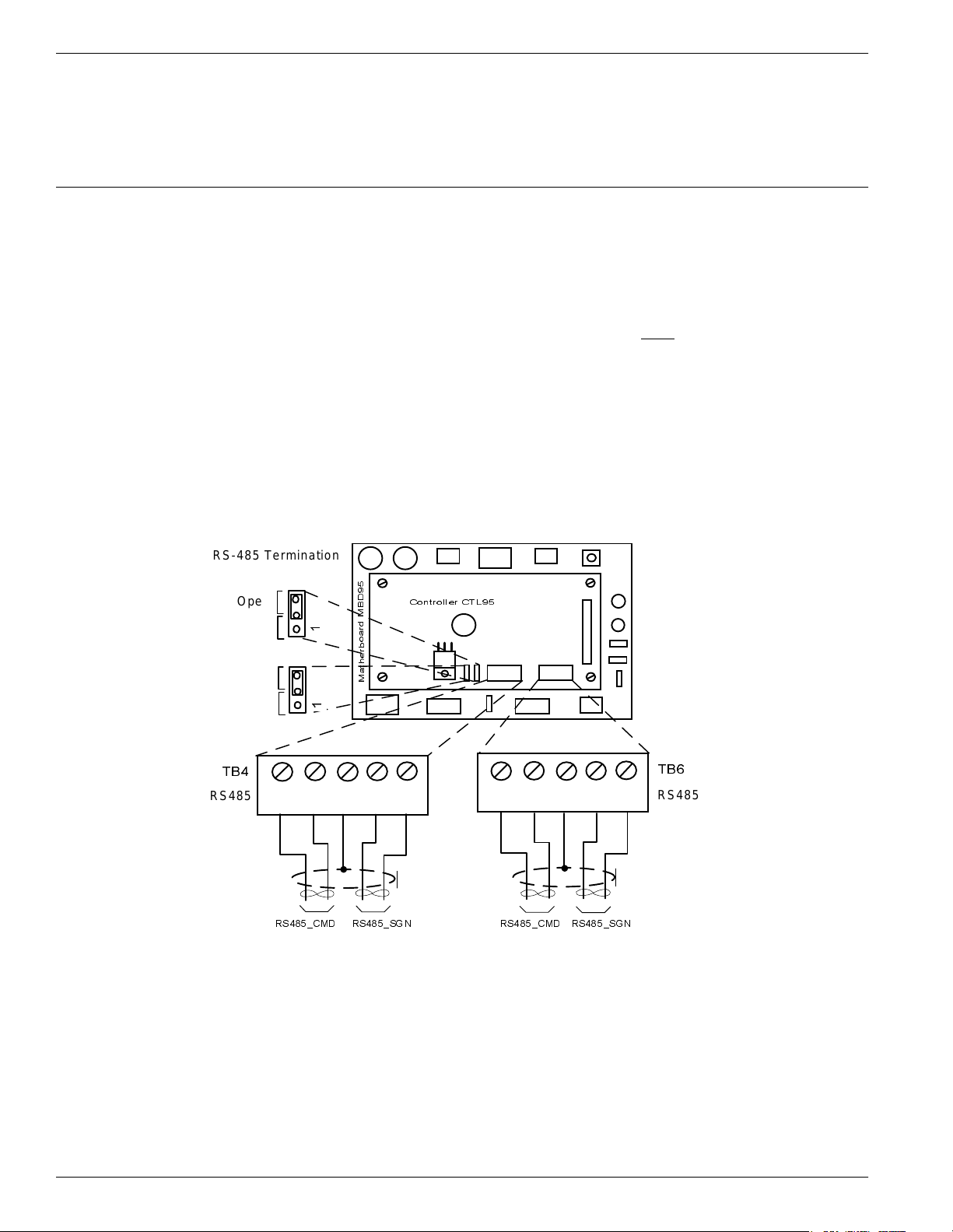
Figure 2-4: Connections and Jumper Settings for the Exciter Communication Line. . . . . . . . . . . . . 2-6
Figure 2-5: Power Supply Connections . . . . . . . . . . . . . . . . . . . . . . . . . . . . . . . . . . . . . . . . . . . . . . . . . 2-8
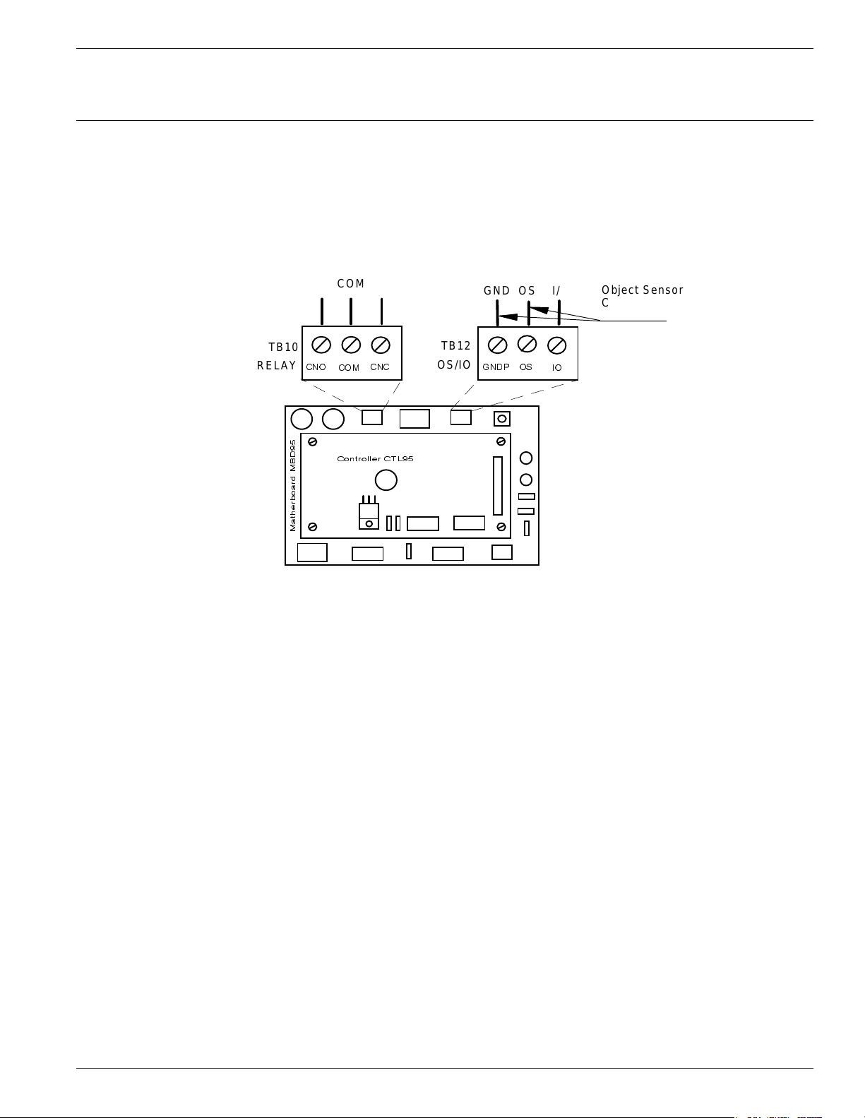
Figure 2-6: External Devices Connections . . . . . . . . . . . . . . . . . . . . . . . . . . . . . . . . . . . . . . . . . . . . . . 2-9
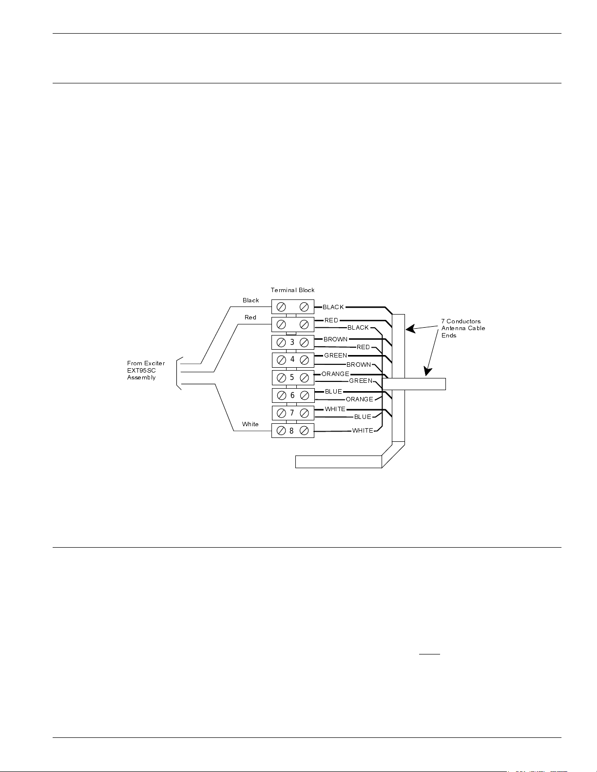
Figure 3-1: LF Antenna Connections . . . . . . . . . . . . . . . . . . . . . . . . . . . . . . . . . . . . . . . . . . . . . . . . . . 3-3
List of Figures
Figure 3-2: Connections and Jumpers Settings for the RS-485 Communication Lines . . . . . . . . . . . 3-4
Figure 3-3: Exciter E95 Power Supply Connections . . . . . . . . . . . . . . . . . . . . . . . . . . . . . . . . . . . . . . . 3-5
Figure 5-1: Connecting the Reader to a PC/Laptop . . . . . . . . . . . . . . . . . . . . . . . . . . . . . . . . . . . . . . . 5-2
Figure 5-2: Setting Up the Exciter’s Address . . . . . . . . . . . . . . . . . . . . . . . . . . . . . . . . . . . . . . . . . . . . 5-5
Figure 5-3: LF Signal Measurement . . . . . . . . . . . . . . . . . . . . . . . . . . . . . . . . . . . . . . . . . . . . . . . . . . . 5-6
Figure 6-1: Programming Site . . . . . . . . . . . . . . . . . . . . . . . . . . . . . . . . . . . . . . . . . . . . . . . . . . . . . . . . 6-1
List of F i gu r es 1
Page 10

List of F i gu r es
This page intentionally left blank.
2 List of Figures
Page 11

What This Manua l Contains
This manual gives procedures for installing and configuring the Reader R95 and the
Exciter E95, and programming the Transponder T95. It also gives you maintenance
and troubleshooting procedures.
Summary A summary of the contents of this manual is given below:
Chapter 1, Introduction, describes the Transponder Identification System and the
Postal RFID System. It also gives information on the 95 Series RFID System
configuration principles.
Chapter 2, Reader R95 Installation and Connections, explains how to install and
connect the Reader, set the jumpers for the interfaces, and connect external devices to
the Reader, if necessary.
What This Manual Contains
Preface
Chapter 3, Exciter E95 Installation and Connections, explains how to assemble the
Exciter using the LF antenna kit and the Enclosure E95 kit, make the LF antenna
connection, connect the serial interfaces and power supply, set the jumpers for the
interfaces, and connect remote devices to the Reader.
Chapter 4, Power Supply TRM95 Installation and Connection, explains how to install
the unit and make input and output connections to the unit.
Chapter 5, Configuration and Operation, provides procedures for setting up and
configuring a 95 Series RFID System.
Chapter 6, Programming and Testing the Transponder T95, explains how to set up a
site and gives procedures for programming the Transponder PT21.
Chapter 7, Troubleshooting, describes maintenance and troubleshooting procedures
that you must follow when using the 95 Series RFID System.
Appendix A, Specifications, gives electrical, environmental, and physical
specifications for the Transponder PT21, the Reader R95, the Exciter E95, and for the
complete 95 RFID System.
Appendix B, Transponder T95 Messages, describes the PT21 Message format.
Appendix C, Excitation Modes, describes the various excitation modes (signal
descriptions) and their associated parameter settings.
Appendix D, Reader Software Upgrade Procedure, describes the procedures for
upgrading the Reader R95 (P/N 600405) main software using the serial interface
RS232 or RS485.
The Glossary is an alphabetical listing of terms and acronyms used in this manual.
Preface i
Page 12

What This Manual Contains
Related Manuals
Technical Guide 95 Series RFID System Technical Guide. This Guide describes the 95 Series RFID
System. It includes operation principles, block diagrams and electrical schematics for
all equipment and assembly parts for the 95 Series RFID System.
Reference Guide 95 Series RFID System Reference Guide. This Guide describes all the commands that
control the RFID operating system.
Text Conventions Helvetica is used for commands you must type exactly as it appears.
Italics is used for document titles, file names and new terms being defined.
Courier is used for messages displayed on the screen.
ii Pref ac e
Page 13
This chapter describes Transponders and their functions, the purpose of the Postal
RFID System and its uses. It also gives information on the 95 Series RFID System
configuration principles.
Transpo nd er Identification S y stem
The purpose of a data capture or identification system that uses a Transponder as an
identification token is:
• To automatically identify animate or inanimate objects having attached a
Transponder with an unique identifier
Transponder Identification System
Chapter 1
Introduction
• To ensure that information is available in a format that can be readily accepted by
a computer
• To minimize the possibility of errors in the identification process.
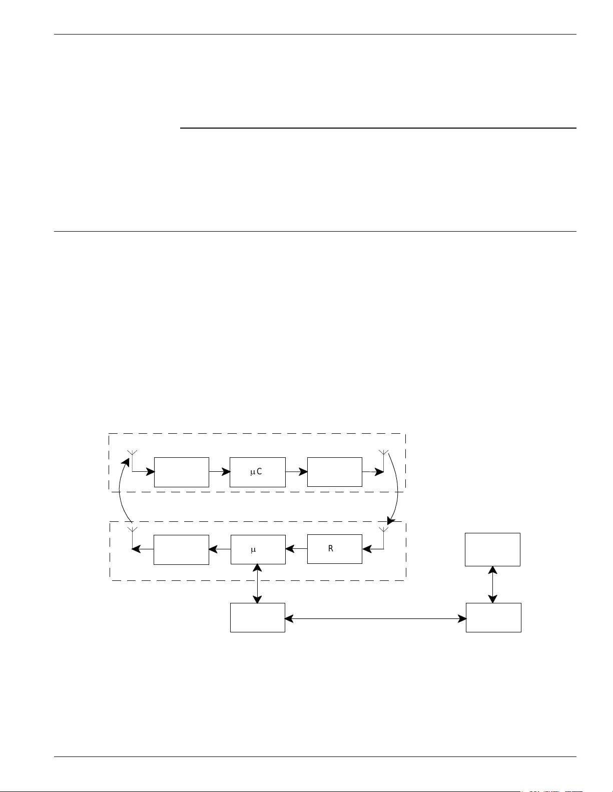
The concept of Radio Frequency Identification (RFID) is presented in Figure 1-1.
Transponder
Rx
Uplink
Tx
Reading Point
µ
C
µ
C
Int er fac e
Tx
Downlink
Rx
Main
PC
Int er fac e
Figure 1-1: RFID Concept
Introduction 1- 1
Page 14

RFID Specific Terms
RFID Specific Terms
Transponder Transponders are devices that receive an excitation signal, and respond by
transmitting back a message. Transponders that are used in identification systems
are sometimes referred to as electronic tags or tags.
Excitation Signal The excitation signal may be in the form of electromagnetic energy and can operate
anywhere in the RF spectrum from a low-radio frequency to infra-red light. It can also
have a special signature (pattern, coding, etc.) to avoid false or unwanted excitations.
When there is no excitation signal, the Transponder is dormant (in sleep mode).
Transponders do not transmit information involuntarily.
Response Signal The Transponder’s response can be a separate RF transmission or a supplementary
modulation of the excitation signal. The response signal contains information that
allows you to identify each Transponder and the object to which it is attached. Some
or all of this information may be stored in memory that can either be pre-coded and
unalterable, or reprogrammable.
Reading Points Reading Points are installed at strategic areas on the site where you want to identify
objects that are passing within a specified range. Reading Points generate the
excitation signal and receive signals transmitted by the Transponders. Data captured
from the Transponders is then transferred to the main computer. In so doing, the
Reading Point functions as a relay or an interface that transfers data from the
Transponders to the main computer and vice-versa.
Communication Links When using Transponders and Reading Points, two wireless communication links
exist. They are: Uplink - from the Reading Point to the Transponder, and Downlink from the Transponder to the Reading Point.
RFID System Automatic identification systems vary in their complexity. An example of a simple
system is a car-park barrier that provides automatic vehicular-access control. A more
complex example is a network of on-line Readers and Exciters that communicate with
a host computer that is managing an automated industrial facility.
Postal RFID System
The International Postal Corporation (IPC) required international end-to-end mail
performance monitoring to implement new management and financial control
systems. This monitoring and controlling is supported by an international agreement
known as REIMS (Remunerating Exchanges of International Mails).
The Postal RFID System was developed in response to the IPC’s requirements.
The main objective of the Postal RFID System is:
• To monitor the movement of the probe letters at key points in the system
• To supply evidence of mailing system performance
• To highlight problem areas.
1-2 Introduction
Page 15

95 Ser ie s R FID System C onfigu ration Principl es
By using a RFID system comprising of a population of Transponders and strategically
placed Readers and Exciters, you can electronically monitor the path of test letters
through the collection and delivery process, particularly at points between Postal
administrations and their agents.
Each probe letter includes a RFID Transponder bearing a unique identification. The
probe letters are posted, sorted, and delivered in the same way as normal letters. As
they pass pre-determined points en-route (Reading Points/identification zones), the
Transponders are identified. The collected information is then read and stored on
local computers. This information is downloaded on demand to a Central
Management System (CMS).
The Postal RFID System includes the following main specific equipment:
• Transponders T95 carrying the identification data
• Exciters E95 to generate an electromagnetic field that excites the Transponder
T95
• Readers R95 to receive data transmitted by the Transponder T95 and to relay this
information via the RS-485 interface to the main computer
• Power Supply TRM95 to power Readers R95 and Exciters E95 from the local AC
main supply.
IMPORTANT Each piece of equipment can have different commercial models (Transponders T95B,
T95C, TRD95, and TBC95, PT21), but they behave similarly. This manual refers to
them as a generic T95 model.
95 Series R F ID Sy ste m C o nf igu r ation Prin ciples
The RFID System is highly configurable, allowing you to setup operational
parameters for the optimum performance of the System. The sections that follow give
some basic information regarding the 95 Series RFID System configuration. A
detailed description of the configuration, with a focus on an IPC implementation, is
given in Chapter 5, Configuration and Operation.
Communication Links There are several communication links between the components of the 95 Series RFID
System. As a general rule, all equipment attached to a particular link must have the
same parameters settings to communicate. Some communication links can be
configured, others, however, have fixed configurations, as follows:
• Reader-to-Transponder: excitation (LF=125.0 kHz) - configurable;
writing (infrared) - fixed configuration.
• Transponder-to-Reader (UHF-433.92 MHz) - configurable.
• Reader-to-Exciter and Exciter-to-Reader (RS485_COM, RS485_SGN) - fixed
configuration.
• Reader- to-Main PC and Main PC-to-Reader (RS-232 or RS-485) - configurable.
System Parameters Parameters controlling the 95 Series RFID System’s configuration are logically
organized in groups. For a detailed explanation on the meaning and usage of the
parameters, refer to the 95 Series RFID System Reference Guide. The parameters
Introduction 1- 3
Page 16

95 Ser ie s R FID System C onfigu ration Principl es
settings that control the hardware configuration, is described in Chapter 3, Theory of
Operation in the 95 Series RFID System Technical Guide. This chapter gives reasons
for using certain parameters for configuring the hardware.
System Code A Reader R95 needs a System Code to function properly. You use the ISC parameter
to set the System Code the first time. The System Code is a specially encoded number
that distinguishes the RFID System from all other similar systems in use. By
obtaining your System Code from Kasten Chase, you are guaranteed a unique System
Code.
Reader Address When a Reader is part of a network, it must have a unique address. The address is set
by the IAD parameter. Once the Reader has an address assigned, it will only process
commands with the address field matching the Reader’s address. In this way, you can
direct commands over the network to a specific Reader.
Real Time Clock The Reader R95 has an on board Real Time Clock. Make sure that the date and time
is correctly set. The time can be queried and set using the IUT parameter. The time
must be adjusted on Jan. 1st and Feb. 29th.
Receiving UHF Data The Reader needs to know the data format in which the Transponder is transmitting
information to properly receive and interpret the information. The Reader’s setting
can be checked and modified by the Group R parameters.
A simple method of matching an unknown Transponder with the Reader’s parameters
setting is given below:
1. Use the programming setup described in Chapter 6, Programming and Testing the Transponder T95.
2. Query the Transponder. (See the Q command).
3. Check the Transponder’s parameters using the Group T parameters.
4. Set an identical set of parameters for the Reader using the Group R parameters.
Reader Data Handling Data that is captured from the Transponder is usually stored in an internal buffer. It
is then sent to the monitoring equipment either voluntarily (if DAR= Y), or in response
to a query command. You can customize the format and the fields using the Group D
parameters. By setting appropriate values, you can greatly simplify the
implementation of the monitoring software.
Reader Serial Port When setting the serial port parameters, remember that communication with the
monitoring equipment can result in a bottleneck in the RFID System. We recommend,
therefore, using the highest baud-rate available. Also, the line turn-around delay
(STD parameter) can greatly degrade the RFID System’s performance. This
parameter must be set to 0, unless required otherwise. For more information on the
Group S parameters, refer to the 95 Series RFID System Reference Guide.
Reader Reset There are two main ways to reset the Reader:
• Hardware reset
• Software reset.
For the hardware reset, switch off the Reader’s power supply for a least 5 seconds.
1-4 Introduction
Page 17

95 Ser ie s R FID System C onfigu ration Principl es
For the software reset, press the RESET button on the Motherboard MBD95 twice, or
type the command:
:RESET<Enter>
The software reset resets the Microcontroller. The hardware reset resets the
Microcontroller and runs a complete memory test.
Exciter Address When an Exciter E95 is part of a network, it must have an unique address. You can
set the Exciter’s address in a binary format between 0001 and 1110, using the S1
switch on the EXT95SC board.
Once an address is assigned, the Exciter will only process commands with a matching
address field. In this way, you can direct commands in the network to a specific
Exciter E95.
Note Address es 0000 and 1111 are reserved for special modes of operation.
Introduction 1- 5
Page 18

95 Ser ie s R FID System C onfigu ration Principl es
This page intentionally left blank
1-6 Introduction
Page 19

Before You Begin
Before You Begin
Chapter 2
Reader R95 Ins t allation and Conn e cti o ns
This chapter explains how to:
• Install the Reader Module Assembly into the Reader’s enclosure
• Connect the serial interfaces and the power supply
• Set the jumpers for interfaces
• Connect the external devices to the Reader R95 (optional)
Before installing the Reader:
• Read Chapter 4, Setup Guidelines in the 95 Series RFID System Technical Guide.
• Have at your disposal, the complete approved documentation describing the RFID
System configuration, equipment location, and wiring distances between the
equipment (see the Site Survey Documentation).
• Check whether the Reader’s enclosure, power supply and interconnection cable
with the main PC are installed on the site according to the approved
documentation (see the Site Survey Documentation).
• Set a color table for each interface and power supply cables. Pay special attention
to the interface terminals, cable shields, and the ground wires.
• Check whether the Reader’s Kit (P/N 600418) is complete according to the product
shipping list.
Mechanical Assembling
To assembly the Reader R95, refer to assembly drawing M900199 in Chapter 8, Power
Supply Assembly Drawings, and complete the following steps:
1. Install the RF assembly cables (P/N 50053) on the Reader’s enclosure using a
13 mm fix key.
2. Install the Reader R95 Module Assembly (P/N 500048) into the Enclosure Base
and secure it using the four 6-32x1/4 inch screws from the Reader R95 Kit. See
drawing M900120.
3. Connect the two RF cables to the RF connectors on the Receiver Board CRM95
(middle board of the Reader Module Assembly).
Reader R95 I n stallat ion and Co nnections 2-1
Page 20
Connecting the RS-232 Communication Line
Connecting the RS-232 Communic ation Line
The RS-232 data transmission line is used for point-to-point communication with a
local PC. This connection can be used during the 95 Series RFID System configuration
or troubleshooting. The RS-232 connector and jumper are located on the Motherboard
MBD95. The MBD95 is the bottom board of the Reader Module Assembly.
Note For the RS-232 line, use specially designed cables only
or a standard PC cable used for RS-232 interconnections. For more information, see
the 95 Series RFID System Technical Guide.
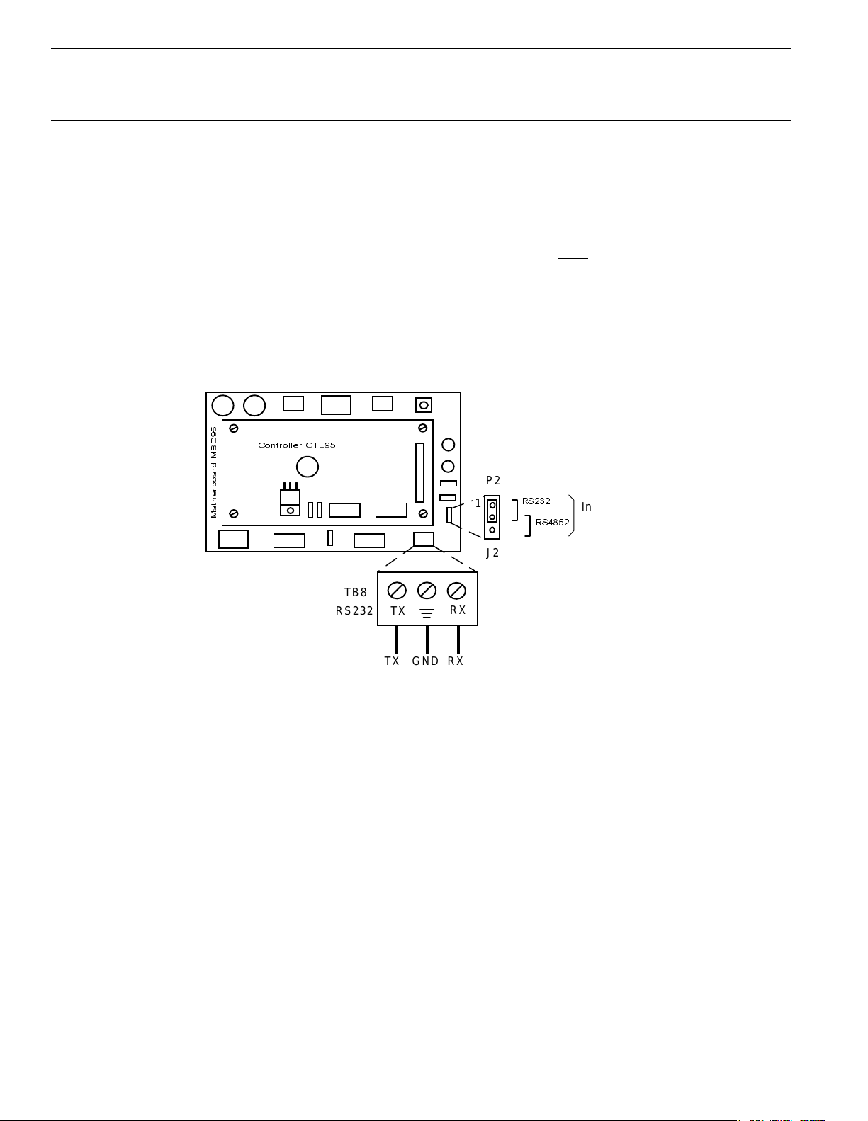
To connect the RS-232 communication line to the Reader, refer to Figure 2-1 below.
Controller CTL95
P2
Matherboard MBD95
TB8
RS232
TX
TX GND RX
1
RX
RS232
RS4852
J2
, such as, BELDEN type 8102,
Interface
Selecti on
Complete the following steps:
1. Unplug terminal block TB8 from connector TB7.
2. Connect the communication wires TX, GND and RX to the corresponding TB8 pins.
3. Place the jumper P2 between pins 1-2 of J2 (RS-232 configuration).
4. Plug terminal block TB8 back into connector TB7.
2-2 Re ad er R95 I n stallat io n an d Co nnections
Figure 2-1: Connections and Jumper Settings for the RS-232 - PC Communication Line
Page 21
Connecting the RS-485 Two-Wire Communication Line
Connecting the RS-485 Two-Wire Communication Line
The RS-485 is a standard data communication line for an industrial environment. For
detailed information on the two-wire RS-485 interface (half-duplex), see the 95 Series
RFID System Technical Guide. The RS-485 connectors and jumpers are located on the
Motherboard MBD95. The MBD95 is the bottom board of the Reader Module
Assembly.
Notes 1. For the RS-485 line, use specially designed cables only
9841, or similar. For more information, see the 95 Series RFID System Technical
Guide.
2. To simplify the RS-485 multidrop-type connection, the two RS-485 connectors,
TB4 and TB6 are wired in parallel on the MBD95. Connect the incoming RS-485
cable to one connector and the outcoming RS-485 cable to the other.
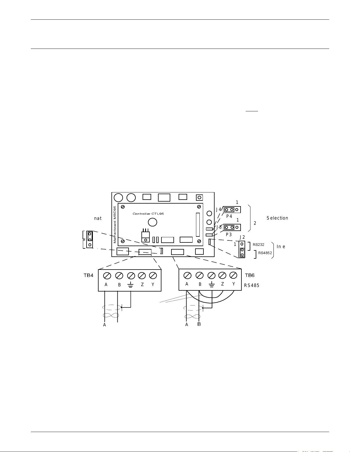
To connect RS-485 communication lines to the Reader, refer to Figure 2-2 below.
J4
P4
J3
P3
RS-485 Termination
J1
Open
Load
P1
1
Controll er CTL95
Matherboard MBD95
, such as, BELDEN type
1
RS485 Interface
1
1
Type Selection
2 wir e
J2
RS232
P2
RS4852
Interface
Select ion
TB4
RS485
In-coming cable
A Y
B
A
B
Figure 2-2 : Conne ct ions and Jumper S ettings for the RS -4 85 Two-Wire C om mu nic ation Line
Z
Wire Jumpers
A
A
B
Out-coming cable
B
TB6
Z
Y
RS485
Reader R95 I n stallat ion and Co nnections 2-3
Page 22

Connecting the RS-485 Four-Wire Communication Line
Complete the following steps:
1. Unplug terminal blocks TB4 and TB6 from connectors TB3 and TB5 respectively.
2. Run the incoming and outcoming RS-485 cables through the cable grips into Reader’s enclosure.
3. Connect a short piece of wire between pins A and Y of terminal block TB4 (or
TB6). Connect another wire between pins B and Z of terminal block TB4 (or TB6).
4. Connect the two-wire communication line to the corresponding pins A and B of
terminal block TB4 (or TB6). Connect the cable shield to the pin marked with the
ground symbol on terminal block TB4 (or TB6).
Caution Before you install the RFID System, label the 2 wires on the RS-485 line A and B.
Keep this naming convention for all connections made on this RS-485 communication
line.
5. Place jumpers P3 between pins 2-3 of J3 and P4 between pins 2-3 of J4 to set the
half-duplex mode for the RS-485 interface.
6. Set the RS-485 communication line terminating load. The ends of a multidrop
network line can be easily identified, because only one RS-485 cable is connected
to that equipment. To connect a 120 ohm terminating load, place the jumper P1
between pins 1-2 of J1. For any other equipment connected to this RS-485
communication line, place the jumper P1 between pins 2-3 of J1.
7. To select with the RS-485 interface, set the jumper P2 between pins 2-3 of J2.
8. Plug terminal blocks TB4 and TB6 into connectors TB3 and TB5 respectively.
Connecting the RS-485 Four-Wire Communication Line
The four-wire RS-485 data-communication line is the recommended variant for
connecting the Readers to the main PC. For detailed information regarding the fourwire RS-485 interface (full-duplex), see the 95 Series RFID System Technical Guide.
The RS-485 connectors and jumper are located on the Motherboard MBD95. The
MBD95 is the bottom board of the Reader Module Assembly.
Notes 1. For RS-485 line, use a specially designed cable only
or similar. For more information, see the 95 Series RFID System Technical Guide.
2. To simplify the RS-485 multidrop-type connection, the two RS-485 connectors,
TB4 and TB6 are wired in parallel on the MBD95. Connect the incoming RS-485
cable to one connector and the outcoming RS-485 cable to the other.
, such as, BELDEN type 9842,
2-4 Re ad er R95 I n stallat io n an d Co nnections
Page 23
Connec t i ng the RS -485 Four -Wire C o m munication Line
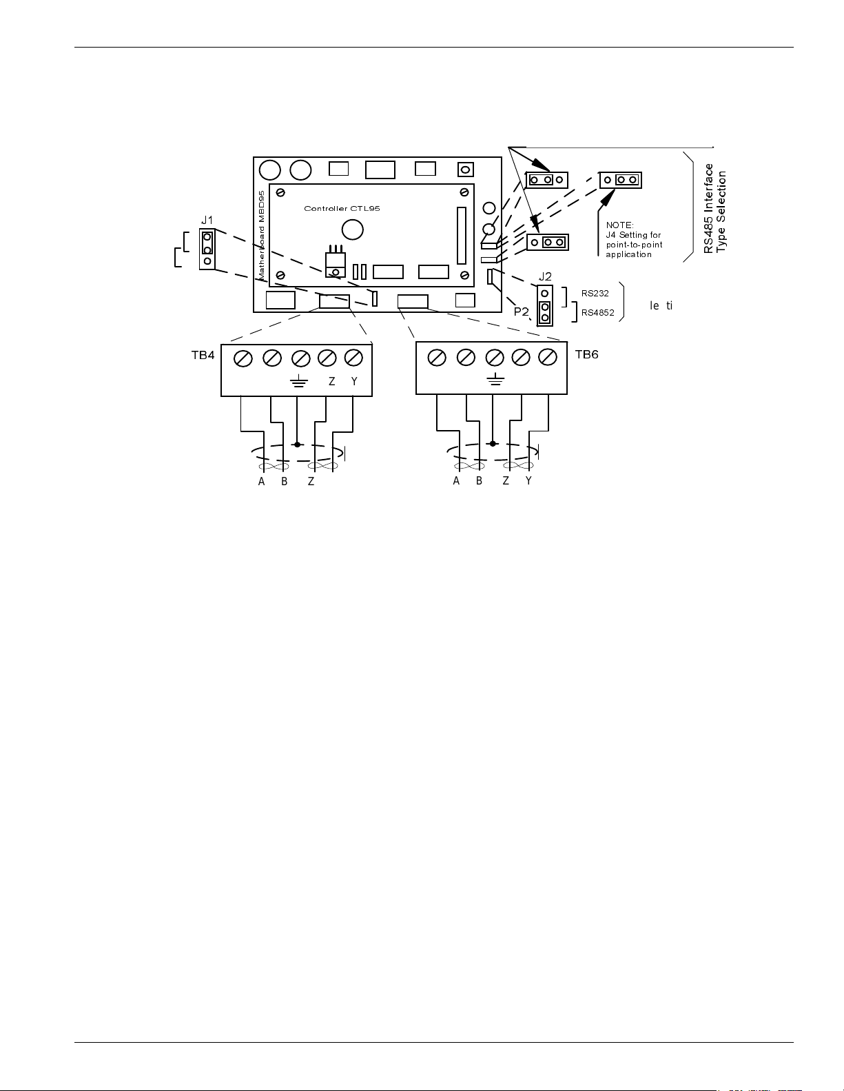
To connect the RS-485 communication lines to the Reader, refer to Figure 2-3 below.
Standard Configuration - 4 wires
RS485 Termination
J1
Open
Load
1
TB4
RS485
Incoming cable
Controller CTL95
Matherboard MBD95
A B Z Y
A B Z Y
Figure 2-3 : Conne ct ions and Jumper S ettings for the RS -4 85 Four-Wire Com munication Line
P4
J2
1
P2
A B Z Y
A B Z Y
1
J4
1
J3
P3
RS232
RS4852
TB6
RS485
Outcoming cable
1
P4
NOTE:
J4 Setting for
point-to-point
applic at io n
J4
Interface
Selection
RS485 Inter face
Type Selection
Complete the following steps:
1. Unplug terminal blocks TB4 and TB6 from connectors TB3 and TB5 respectively.
2. Run the RS-485 incoming and outcoming cables through the cable grips into
Reader’s enclosure.
3. Connect the four-wire communication line to the corresponding pins A, B, Z and Y
on terminal block TB4 (or TB6). Connect the cable shield to the pin indicated by
the ground symbol on terminal block TB4 (or TB6).
Caution Before installing the RFID System, label the 4 wires on the RS-485 line A, B, Z and Y.
Keep this naming convention for all connections made on this RS-485 communication
line.
4. Place jumpers P3 between pins 1-2 of J3 and P4 between pins 2-3 of J4 to set a
full-duplex multipoint communication mode on the RS-485 interface.
Note For a full-duplex point-to-point communication mode set, however, you have to place
the jumper P4 between pins 1-2 of J4.
5. Set the RS-485 communication line terminating load. The ends of a multidrop
network line can be easily identified, because only one RS-485 cable is connected
to that equipment. To connect a 120 ohm terminating load, place the jumper P1
between pins 1-2 of J1. For any other equipment connected to this RS-485
communication line, place the jumper P1 between pins 2-3 of J1.
Reader R95 I n stallat ion and Co nnections 2-5
Page 24
Connecting the Exciter Communication Line
6. To select with the RS-485 interface, place the jumper P2 between pins 2-3 of J2.
7. Plug terminal blocks TB4 and TB6 into connectors TB3 and TB5 respectively.
Connecting the Exciter Communication Line
Two separate RS-485 two-wire interfaces are used to communicate between Readers
and Exciters. For more information, see the 95 Series RFID System Technical Guide.
The RS-485 connectors and jumpers for these lines are located on the Controller
Board CTL95. The CTL95 is the top board of the Reader Module Assembly.
Notes 1. For the RS-485 line, use specially designed cables only
9842, or similar. For more information, see the 95 Series RFID System Technical
Guide.
2. To simplify the RS-485 multidrop-type connection, the two RS-485 connectors,
TB4 and TB6, are wired in parallel on the MBD95. Connect the incoming RS-485
cable to one connector and the outcoming RS-485 cable to the other.
To connect the RS-485 communication lines to the Reader, refer to Figure 2-4 below.
RS-485 Termination
J1
Matherboard MBD95
Controll er CT L 95
A1 B1 G A2 B2
TB6
RS485
Open
Open
TB4
RS485
P1
Load
Load
1
J2
P2
1
A1 B1 G A2 B2
, such as, BELDEN type
In-coming cable
2-6 Re ad er R95 I n stallat io n an d Co nnections
Out-coming cable
RS485 _ CMDRS485_SGNRS485 _ CMD RS485_SGN
Figure 2-4: Connections and Jumper Settings for the Exciter Communication Line
Page 25

Connec ting the Powe r Su pp ly
Complete the following steps:
1. Unplug terminal blocks TB4 and TB6 from connectors TB3 and TB5 respectively.
2. Run the RS-485 incoming and outcoming cables through the cable grips into the
Reader’s enclosure.
3. Connect the four-wire communication line to the corresponding pins A1, B1, A2,
and B2 on terminal block TB4 (or TB6). Connect the cable shield to the pin
marked G on terminal block TB4 (or TB6).
Caution Before installing the RFID System, label the two wires of one line of RS-485 as A1 and
B1, and the other two wires of RS-485 as A2 and B2. Keep this naming convention for
all connections made on this RS-485 communication line.
4. Set the RS-485 communication line terminating load for each two-wire line. The
ends of a multidrop network line can be easily identified, because only one RS-485
cable is connected to that equipment. To connect an 100 ohm terminating load on
each separate RS-485 line, place jumper P1 between pins 1-2 of J1, and jumper P2
between pins 1-2 of J2. For any other equipment connected to this RS-485
communication line, place jumpers P1 between pins 2-3 of J1, and P2 between
pins 2-3 of J2 respectively.
5. Plug terminal blocks TB4 and TB6 into connectors TB3 and TB5 respectively.
Connecting the Power Supply
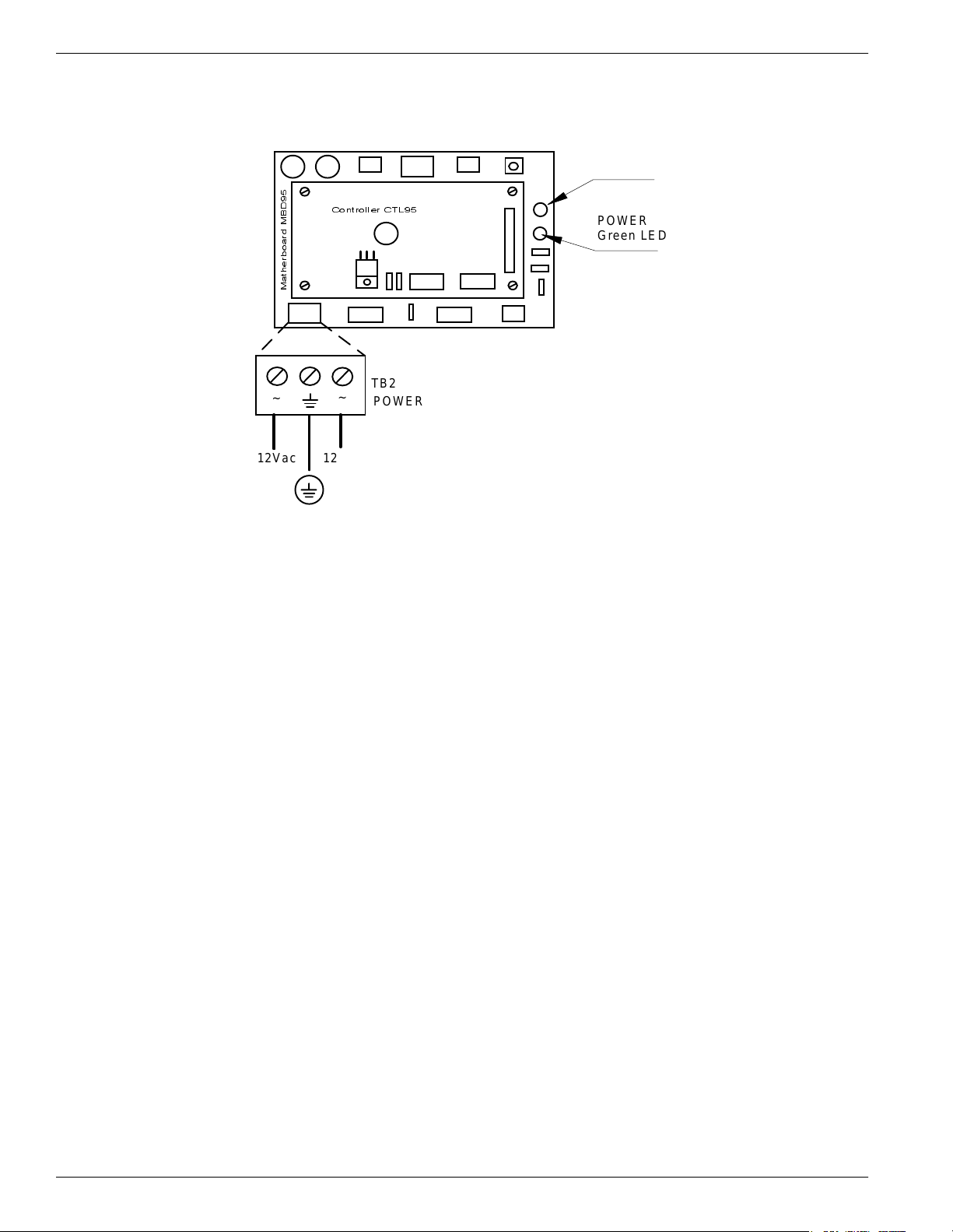
The Reader R95 requires a 12Vac or 13 to 16Vdc power source, and a maximum
current of 0.3A. For more information on the Reader, see Appendix A, Specifications.
The power supply connector is located on the Motherboard MBD95. The MBD95 is the
bottom board of the Reader Module Assembly (P/N 500048).
Notes 1. To connect the power supply, use electrical wire gauge 16 AWG (minimum).
2. The main ground connection of the Reader is on the power supply connector. It is
indicated by the ground symbol. Use an electrical wire with at least gauge 16AWG
for the main ground connection.
3. We recommend using Lyngsoe’s Power Supply, model TRM95/120V or TRM95/
230V, as required by the local AC power line voltage.
Reader R95 I n stallat ion and Co nnections 2-7
Page 26
Connecting the Power Supply
To connect the power supply to Reader R95, refer to Figure 2-5 below.
DATA
Red LED
Controll er CT L 95
Matherboard MBD95
~
12Va c 12Va c
~
Figure 2-5: Power Supply Connections
TB2
POWER
POWER
Green LED
Complete the following steps:
1. Unplug terminal block TB2 from its connector TB1.
2. Run the power supply cable through the cable grip into the Reader’s enclosure.
3. Connect the power wires to the TB2 pins marked with the “~” symbol.
4. Connect the main ground connection to the TB2 pin marked with the ground symbol.
5. Switch on the power supply.
6. Check the voltage on terminal block TB2 (between pins marked with the “ ~” symbol).
7. Plug terminal block TB2 into its connector TB1.
8. Re-check the voltage on the terminal block TB2 in Step 6.
9. Check the MBD95 to see whether the green POWER LED goes ON, and the red
DATA LED stays ON continuously for 6-7 seconds and then turns OFF.
10. Switch off the power supply.
2-8 Re ad er R95 I n stallat io n an d Co nnections
Page 27
Connecting External Devices
Figure 2-6 shows you how to connect external devices to the Reader.
Caution Do not exceed the maximum ratings for the relay contacts and Object Sensor input as
stated in Appendix A, Specifications.
Connec t i ng Exte rnal Devic es
SPDT Contacts
TB10
RELAY
COM
NO NC
GND OS I/O
TB12
CNO
Mathe rboard MBD95
CNC GNDP
COM
Controller CT L95
OS/IO
Figure 2- 6 : Exte r nal Devi c es Connections
OS
Object Sensor
Contacts
IO
Reader R95 I n stallat ion and Co nnections 2-9
Page 28

Connecting External Devices
This page intentionally left blank.
2-10 Rea de r R9 5 Ins t a ll ati on and Connections
Page 29

Before You Begin
Before You Begin
Chapter 3
Exciter E95 Installation and Connections
This chapter explains how to:
• Assemble the Exciter E95 using LF Antenna Kit (P/N 600420) and Enclosure E95
Kit (P/N 600421)
• Make the LF antenna connections
• Connect serial interfaces and power supply
• Set the jumpers for interfaces
• Connect remote devices to the Reader R95 (optional)
Before starting the installation:
• Read Chapter 4, Setup Guidelines in the 95 Series RFID System Technical Guide.
• Have at your disposal, the complete approved documentation describing the RFID
System configuration, equipment location, and wiring distances between
equipment (see the Site Survey Documentation).
• Check whether the mechanical supports for the Exciters are installed on the site
according to the approved documentation (see the Site Survey Documentation).
• Set a color table for the serial interfaces and power supply cables. Pay special
attention to the interface terminals, cable shield, and the ground wires.
• Check whether the LF Antenna Kit (P/N 600420) and Enclosure E95 Kit
(P/N 600421) are complete, according to the product shipping list.
Tools To install the Exciter E95, you will need the following tools:
• Screwdriver SR1 (square recess # 1)
• Rubber mallet
• Hexagonal fix key # 10
Excit e r E 95 Inst allatio n and C onnect i ons 3-1
Page 30

Mechan ical Assembling
Mechanical Assembling
To assemble the Exciter E95, refer to the assembly drawing (M900121), and then
complete the following steps.
Assembling the LF Antenna for E95
The antenna frame consists of five separate segments, each with the following
dimensions: two pieces - 0.4m long, two pieces - 2.0m long, and one piece - 1.0m long.
Each segment includes an aluminum tube with an internal rubber hose. The
segments are joined together using plastic corners. The antenna cable (7-wire cable)
runs through the rubber hoses inside the aluminum tubes.
To assemble the antenna, do the following:
1. Starting with one side of the antenna frame that is beside the plastic enclosure
(0.4 m segment), place the corresponding rubber hose inside the aluminum tube,
and run the antenna cable through the rubber hose. Run the cable through a
plastic corner, and secure the plastic corner inside the aluminum tube using a
rubber mallet.
2. Repeat Step 1 for each side of the frame, finishing with the last short segment
(0.4m). You should have a 1x2m rectangular aluminum frame with the antenna
cable inside.
3. Terminate the antenna frame with the plastic base connectors.
4. Place the 90° brackets on each ends of the frame, and secure the frame against the
plastic enclosure using M6 screws, washers and nuts.
5. Connect the antenna frame to the ground lead on the board, by securing the
terminal lug of the ground lead on the EXT95SC electronic board with one of the
M6 screws, as shown on the assembly drawing 600406.
Note Always ensure that the ends of the antenna cable inside the plastic enclosure have the
following dimensions: one - 110mm long and the other - 360mm long. For more
information, see the drawing 600406.
6. Use the self-drill screws (M3.5x9.5) to secure the 1 inch square aluminum tube in
each corner of the LF antenna frame, and to secure the 90° brackets against the
aluminum tubes.
3-2 Exciter E95 Installation and Connections
Page 31
LF Antenna Con n ections
The LF antenna is a 7-turn loop coil with the tap at the first turn. To create this
multiturn loop and the proper tap connection, complete the following steps:
1. Position the antenna cable inside the plastic box as shown in the assembly
drawing 600406. Cut the end closest to the terminal block - 110mm long, and the
other - 360mm long.
2. Remove 80mm of the outside cable jacket, and strip about 8mm from each
conductor isolation.
3. Using a screwdriver, connect the antenna cable conductors in the terminal block
as shown in Figure 3-1 below.
From Exciter
EXT 95 SC
Assembly
Black
Red
Whit e
Te rmi na l Block
1
2
3
4
5
6
7
8
BLACK
RED
BROWN
GREEN
ORANGE
BLUE
WHITE
BLACK
RED
BROWN
GREEN
ORANGE
BLUE
WHITE
LF Antenna Connections
7 Conductors
Antenna Cable
Ends
Figure 3-1: LF Antenna Connections
Connecting the RS-485 Communic ation Lines
The RS-485 connectors and jumpers are located on the Exciter Slave EXT95SC
assembly placed inside the plastic enclosure (see the assembly drawing M900121).
Two separate RS-485 two-wire lines are used to transmit data from/to the Reader. For
detailed information on the RS-485 two-wires interface (half-duplex), see the 95 Series
RFID System Technical Guide.
Notes 1. For the RS-485 line, use specially designed cables only
9842, or similar. For more information, see the 95 Series RFID System Technical
Guide.
2. To simplify the RS-485 multidrop-type connection, the two RS-485 connectors,
TB4 and TB6 are wired in parallel on the EXT95SC board. Connect the RS-485
, such as BELDEN type
Excit e r E 95 Inst allatio n and C onnect i ons 3-3
Page 32
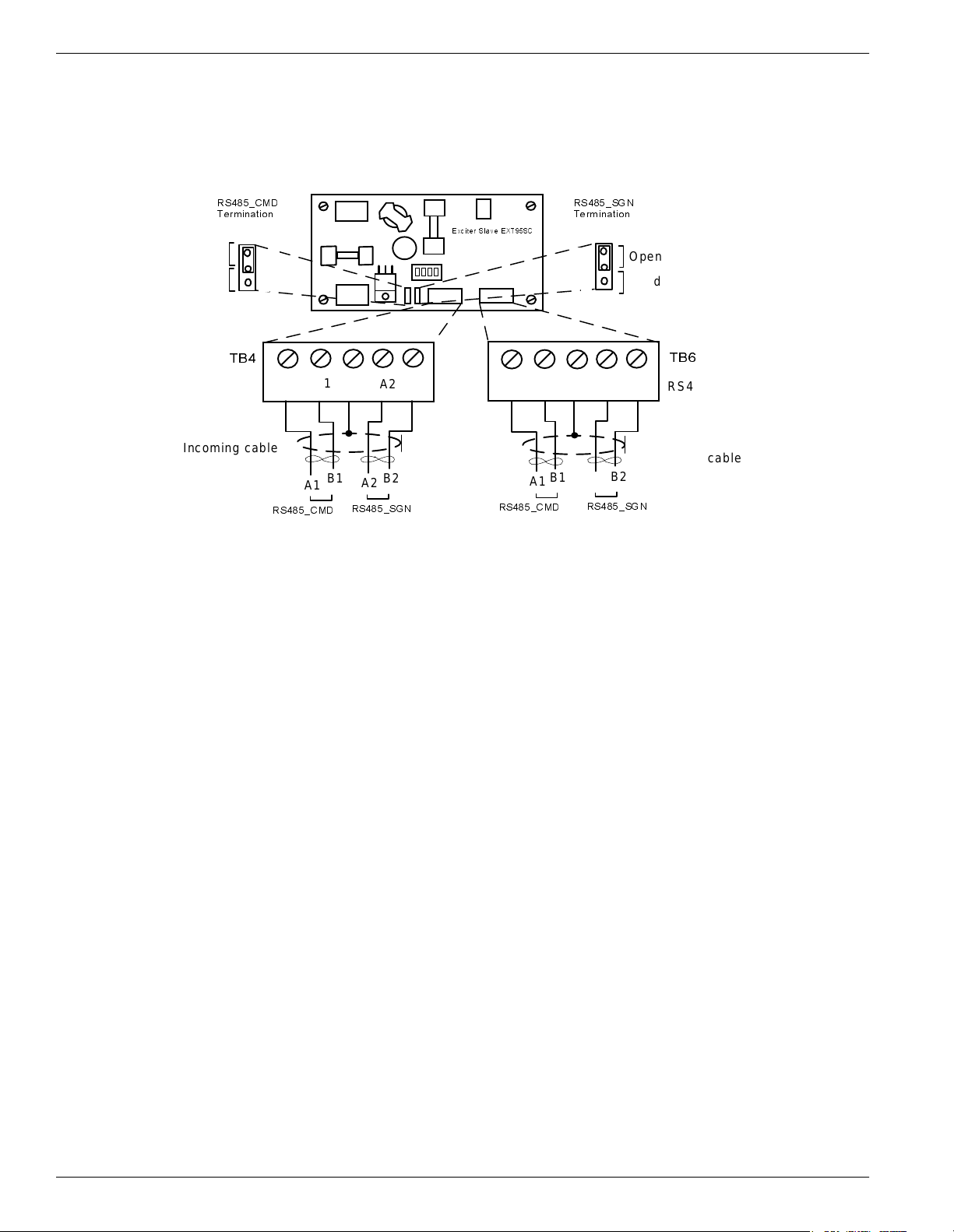
Connecting the RS-485 Communication Lines
incoming cable to one connector and the RS-485 outcoming cable to the other.
To connect RS-485 communication lines to the EXT95SC, refer to Figure 3-2 below.
RS485_CMD
Termination
J1
Open
Load
Incoming cable
P1
1
TB4
Complete the following steps:
RS485_SGN
Termination
Exciter S lav e EXT95SC
B1
A1
RS485_CMD
G G
B1
A1
Figure 3-2: Connections and Jumpers Settings for the RS-485 Communicat ion Lines
A2
RS485_SGN
A2
B2
B2
A1 B1 A2
B1
A1
RS485_CMD
J2
P2
1
A2
RS485_SGN
Open
Load
TB6
B2
RS485RS485
Outcoming cable
B2
1. Unplug terminal blocks TB4 and TB6 from connectors TB3 and TB5 respectively.
2. Run the RS-485 incoming and outcoming cables through the cable grips into the plastic enclosure.
3. Connect the RS485_CMD line to pins A1, B1, and RS485_SGN line to the pins A2,
B2 on terminal block TB4 (or TB6). Connect the cable shield to the pin marked G
on terminal block TB4 (or TB6).
Caution Before installing the RFID System, label the 2 wires on the RS485_CMD line A1 and
B1; label the 2 wires on the RS485_SGN line A2 and B2. Keep this naming
convention for all connections made on these RS-485 communication lines.
4. Set the terminating load for the each RS-485 communication line. The ends of a
multidrop-network line could be easily identified, because only one RS-485 cable
is connected to the equipment.
5. To connect a 100 ohm terminating load to the RS485_CMD line, place the jumper
P1 between pins 1-2 of J1. When connecting any other equipment to this RS-485
communication line, place the jumper P1 between pins 2-3 of J1.
To connect a 100 ohm terminating load to the RS485_SGN line, place the jumper
P2 between pins 1-2 of J2. When connecting any other equipment to this RS-485
communication line, place the jumper P2 between pins 2-3 of J1.
6. Plug terminal blocks TB4 and TB6 into connectors TB3 and TB5 respectively.
3-4 Exciter E95 Installation and Connections
Page 33
Connecting the Power Supply
Connec ting the Powe r Su pp ly
Power Supply Connections
The Exciter requires an 22 Vac or 23 to 28 Vdc power source, and a maximum current
of 0.5 A. For more information, refer to Appendix A, Specifications.
Notes 1. The power connector is located on the EXT95SC assembly.
2. Use an electrical wire with at least a 16 AWG gauge to connect the power supply.
3. The Exciter’s main ground connection is on the power supply connector. It is
indicated by the ground symbol. Use an electrical wire with at least a 16 AWG
gauge for the main ground connection.
4. To power the EXT95SC, we recommend using Lyngsoe’s Power Supply, model
TRM95/120V or TRM95/230V, as required by the local AC power line voltage.
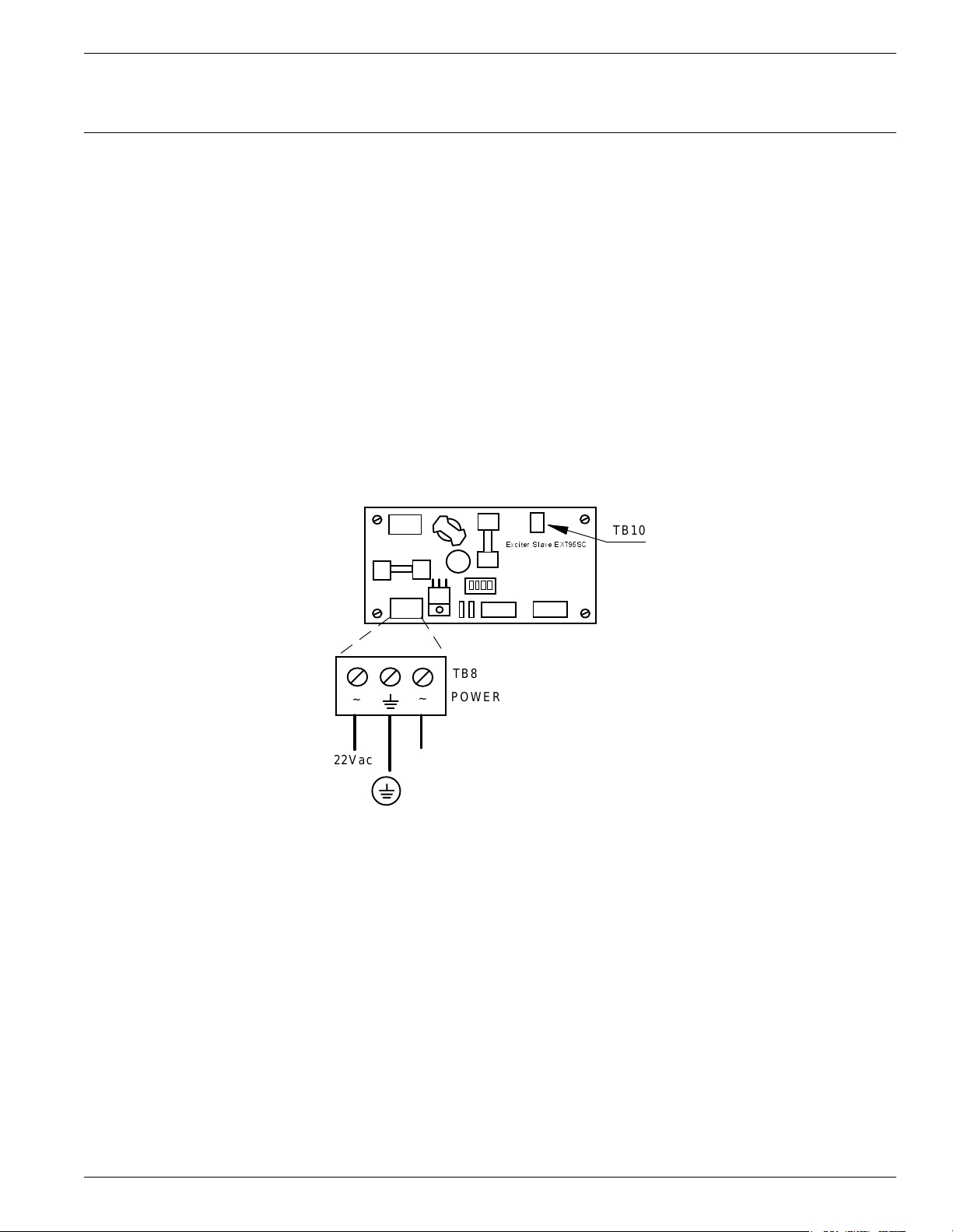
To connect the power supply to the Exciter, refer to Figure 3-3 below.
Exciter Slave EXT95SC
TB10
TB8
POWER
~
22Vac 22Vac
Figure 3-3: Exciter E95 Power Supply Connections
~
Complete the following steps:
1. Remove terminal block TB8 from connector TB7 on the EXT95SC board.
2. Run the power supply cable through the cable grip into the plastic enclosure.
3. Connect power wires to the TB8 pins marked with the “~” symbol.
4. Connect the main ground connection to the TB8 pin marked with the ground
symbol.
5. Switch on the power supply.
Excit e r E 95 Inst allatio n and C onnect i ons 3-5
Page 34

UHF Transmitter - Direct Control (Optional)
6. Check the voltage on the terminal block TB8 (between pins 1-3).
7. Plug terminal block TB8 into connector TB7.
8. Re-check the voltage in Step 6.
9. Check whether the voltage between pins 1 and 2 on terminal block TB10 is
5.0 ± 0.2 V.
10. Switch off the power supply.
UHF Transmitte r - Direct Con tro l (Optio na l)
The UHF transmitter can be also switched on using a hardware control, by creating a
a short between pins 1-2 on terminal block TB10. After this is done, the UHF
transmitter will start transmitting the pre-programmed messages and then stop. To
start another transmission, the contact must be opened and then closed again.
The location of terminal block TB10 on the EXT95SC board is shown in Figure 3-3.
Assembl ing Othe r Models of Exc iters
Lyngsoe provides other models of Exciters with different antenna frame sizes for
particular installations. As an example, see Exciter E95S (P/N 600647). For
mechanical assembling and electrical connections, use a similar procedure as
described in the previous paragraphs and drawing M900113.
3-6 Exciter E95 Installation and Connections
Page 35

Before you Begin
Before you Begin
Chapter 4
Power Supply TRM9 5 In st alla tio n and Conn ectio n
This chapter explains how to:
• Install the Power Supply
• Make the input line and output connections
All data provided in this chapter apply to both Power Supply models TRM95/120V
(P/N 600579) and TRM95/230V (P/N 600626).
Before installing the Power Supply:
• Read Chapter 4, Setup Guidelines in the 95 Series RFID System Technical Guide.
• Have at your disposal, the complete approved documentation describing the RFID
System configuration, equipment location, and wiring distances between
equipment (see the Site Survey Documentation).
• Check whether the mechanical supports for the Power Supply is installed on the
site according to the documentation.
• Check whether all cables are installed on the site according to the documentation
(type, protection, routing, etc.).
• Check whether the Power Supply unit has the correct rating (120V or 230V) that
is suitable for the local AC power lines voltage.
Tools To install the Power Supply, you will need the following tools:
• Phillips screwdriver size # 1)
• Slotted screwdriver 2mm
Installing P ower Supply TRM95
For mechanical details, refer to the Power Supply assembly drawing.
Placement The Power Supply unit can be installed either horizontally or vertically, but must be
secured against its mechanical support with 4 screw (dia. 1/8"). It must be installed in
such a way that the front is easily accessible and visible for inspection. This unit is
designed for indoor use only. You should avoid installing the Power Supply unit in
locations where there is water or excessive humidity. To reduce the risk of
overheating, avoid exposing the Power Supply unit to direct sunlight or near any
heat-emitting devices, such as a room heater or a stove.
Power Supply TRM95 Installation and Connection 4-1
Page 36

Wiring Connec tions and Supply
Safety Please adhere to the following safety precautions:
1. Only authorized personnel are qualified to install and repair the Power Supply unit.
Caution To reduce the risk of an electrical shock, disconnect the AC main supply before
removing the unit’s cover.
2. Use only approved (CSA,UL, IEC) fuses, size 5x20mm, Type “T” (slow-blow), with
appropriate rating (1A for 120Vac, or 0.5A for 230Vac). The correct fuse rating is
marked on the front panel of the Power Supply unit.
3. Ensure that the Power Supply unit is properly grounded. Always connect the unit
to the 3-wire (with grounding) power systems.
4. Ensure that no water does not get inside the unit. Ensure that no foreign objects
get inside the unit.
Wiring Connections and Supply
To get inside the unit, you must first unscrew the two screws that secure the cover.
Once you remove these screws, you can easily lift the cover.
Note To completely detach the cover, you must also remove the cover’s ground connection.
Remember the ground connections must be in place when the unit is operating
normally.
All unused knockout-punch holes (front and back panels) must be plugged with plugs
or similar stoppers. Lyngsoe recommends using the Hole Plug PG11 (P/N 400617)
with a Polyamid Nut (P/N 400645). You have to order these parts separately.
You must secure all cables passing through the front or back panel with cable grips or
connectors (these are not provided). The connectors must match the conduit type used
to protect the cable outside the Power Supply unit. For more information on these
parts, contact Lyngsoe Industries.
For all interconnections (power line, equipment), Lyngsoe recommends using cable
type SJT, PVC jacketed, 3-conductors with a minimum gauge of 16 AWG (0.75 mm
2
conductor nominal cross-sectional area). Lyngsoe recommends BELDEN cable type
19353.
An external disconnecting device will be provided as part of the building’s installation.
The disconnecting device will have an appropriate rating for the AC power line
voltage (minimum 1A for 120Vac or 0.5A for 230Vac). Installation of the external
wiring will comply with the national wiring rules (code) applicable to the site.
-
4-2 Power Supply TRM95 Installation and Connection
Page 37
Connecting Equipment to the Power Supply Unit
Connecting Equipment to the Power Supply Unit
The Power SUpply unit has 2 separate outputs (12Vac/1A and 22Vac/2A) to power up
separate RFID equipment as Readers R95 and Exciters E95. These voltages are
available for connecting an external cable on the Power Supply’s internal terminal
block and is clearly marked.
Attention Do not exceed the load ratings specified for each output: 1A for the 12Vac, and 2A for
the 22Vac. On the 22Vac source, the 2 terminal blocks are connected in parallel for
each output terminal. Always use a 3-wire cable to connect the equipment to the
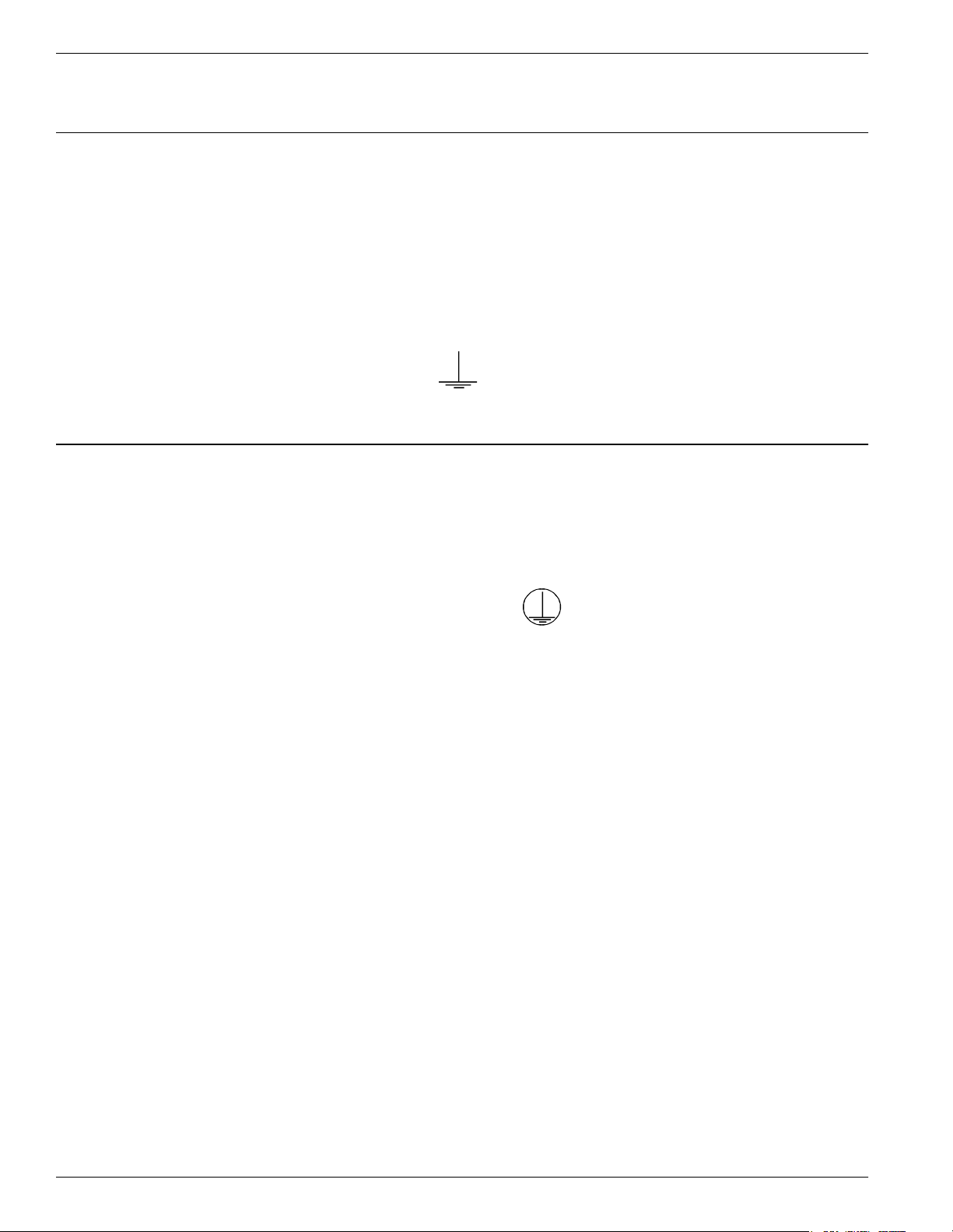
Power Supply unit. Always connect the ground wire of each cable to the terminal
block that is indicated by
Connecting the AC Mains Supply
Connect the power lines cable to the internal terminal block of the Power Supply unit
as follows:
• Live (phase) - to the terminal marked L
• Neutral - to the terminal N
• Ground - to the terminal marked
For more information, see Chapter 8, Power Supply Assembly Drawings.
IMPORTANT Before you connect power to the Power Supply unit, re-check the following:
• The Power Supply model and rating against the installation plan and line voltage
• The Power Supply fuse rating
• All cable connections to the Power Supply’s internal terminal block
• All cable access into the Power Supply’s enclosure, making sur that they are
properly secured and protected.
4-3 Power Supply TRM95 Installation and Connection
Page 38

Connecting the AC Mains Supply
This page intentionally left blank.
4-4 Power Supply TRM95 Installation and Connection
Page 39

Before You Begin
Before You Begin
Chapter 5
Configuration and Operation
This chapter explains how to set-up and configure a 95 Series RFID System. The IPC
implementation is a practical example of the 95 Series RFID System configuration.
For more information about the 95 Series RFID System configuration, refer to the
95 Series RFID System Technical Guide.
Before starting the RFID System configuration, do the following:
1. Check whether all equipment is correctly installed and interconnected according
to the requirements stated in Chapter 2, Reader R95 Installation and Connections
and Chapter 3, Exciter E95 Installation and Connections in this guide.
2. Create a unique address for each Reader and Exciter according to the approved
documentation describing the RFID System configuration (see the specific Site
Survey documentation).
3. Familiarize yourself with the instructions format described in the 95 Series RFID
System Reference Guide, and the system’s functionality described in the 95 Series
RFID System Technical Guide.
4. Refer to the section, 95 Series RFID System Configuration Principles on page 1-3,
for some general explanations on configuring the 95 Series RFID System.
General Procedure Rules
You have to configure each Reader and Exciter in the RFID System.
Lyngsoe recommends that you follow the general rules listed below:
1. Configure each identification zone, one by one, by using a PC/Laptop that is
directly connected to a Reader. By doing this, you can control the Reader, and all
Exciters interconnected to it from this PC.
2. Follow the step-by-step instructions described in this chapter.
3. If you do not obtain the expected results, refer to Chapter 7, Troubleshooting.
Configurati on and Oper ation 5- 1
Page 40
Setting U p the R e ad er / P C C onne ct io n
Setting U p the Read er /P C Connection
To connect the Reader to a PC, do the following:
1. Use the RS-232 or RS-485 communication line to connect the Reader to the PC.
For more information on these communication lines, see Connecting the RS-232
Communication Line, and Connecting the RS-485 Four-Wire Communication Line
in Chapter 2.
For the initial set-up, Lyngsoe recommends using the RS-232 connection with a local,
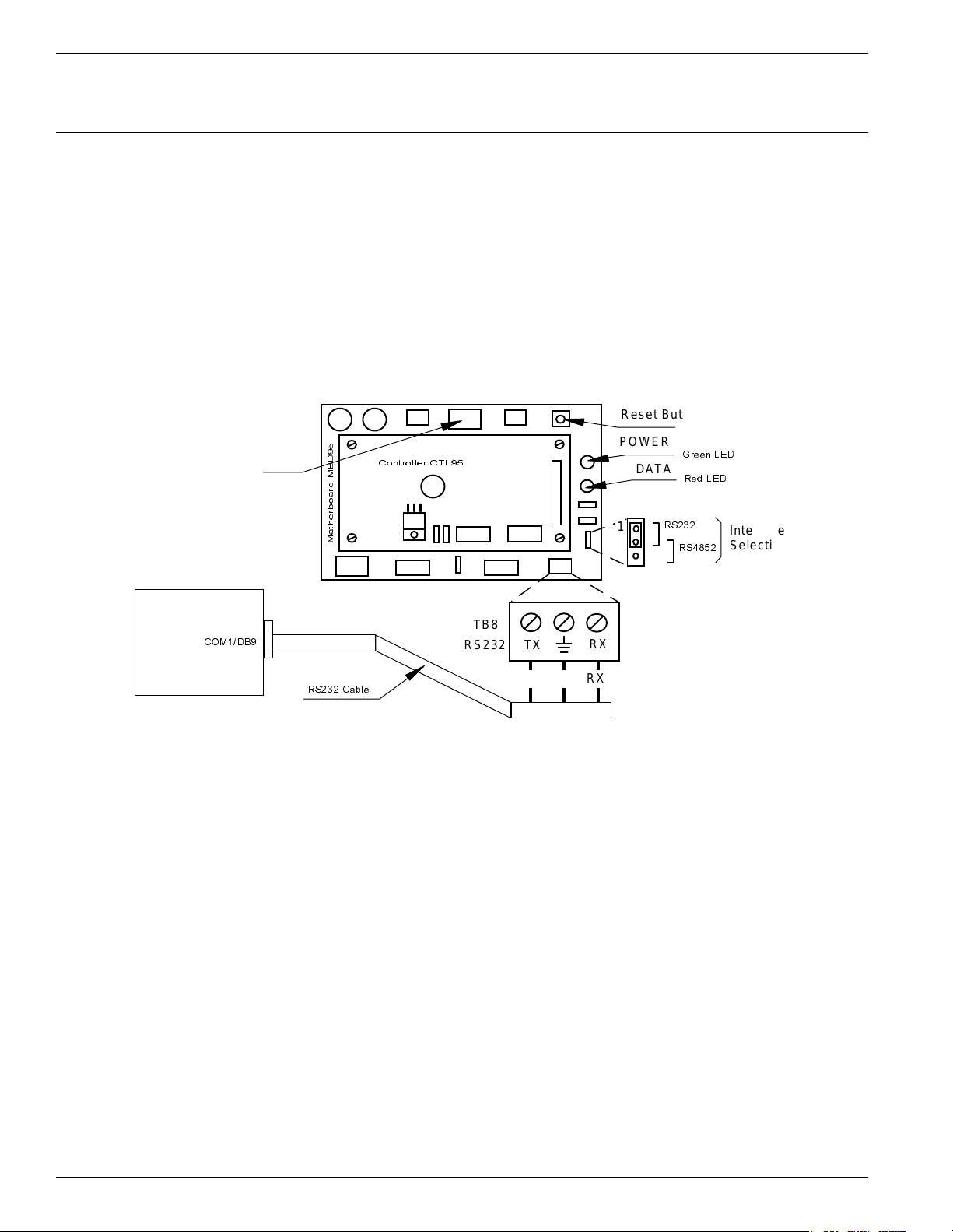
mobile PC (Laptop), as shown in Figure 5-1 below.
Reset Butt on
COM1/DB9
Relay
RS232 Cable
Figure 5-1 : Co nnecting the Reader to a PC/Laptop
Controller CT L95
Matherboard MBD95
TB8
RS232
TX
TX GND RX
RX
POWER
DATA
P2
1
J2
Green LED
Red LED
RS232
RS4852
Interface
Select ion
2. Run a terminal emulation program on the PC, such as, HyperTerminal in
Windows 95, Terminal in Windows 3.x, or Procomm in DOS or any version of
Windows. The recommended configuration for the PC’s port is:
5-2 Co nf iguratio n an d Op er a tion
• Data rate - 19200 bps
• Data bits - 8 bits
•Parity -none
• Stop bits - 1
• Flow control - none
Page 41

Reader’s Power -up Sequence
To verify the Reader’s power-up sequence, do the following:
1. Turn on the power supply to the Reader.
2. Referring to Figure 5-1, check whether the relay on the MBD95 board
immediately clicks, and the green POWER LED is on.
3. Check whether the Reader performs the following power-on test sequence: the red
DATA LED on the MBD95 board remains ON for 6-7 seconds. Afterwards, the
following sign-on message is displayed on the PC’s screen:
DISYS CRM-95 READER (c)Copyright DISYS Corporation 1989-1996.
Notes 1. If you did not assign a System Code identification number (SC) to the Reader, the
DATA LED will flash On and Off at a rate of 1.4 Hz. To set the System Code, type:
your SC
ISC=[
Reader’s Power-up Sequence
] <Enter>
2. If a string of unrecognizable characters appears on the PC’s screen, it means that
the communication link between the Reader and the PC is not set properly. Run
the Learning Procedure, as described below, to establish the correct settings.
Learn ing Proced ure (O pt i on al)
This a special mode of operation, specifically designed to allow a Reader to
communicate with the PC to which it is attached, by adapting itself to the serial frame
format that the PC is using.
To force the Reader into the learning mode, follow the steps below. (See Figure 5-1).
1. Press the RESET button once.
2. Verify whether the DATA LED flashes at a rate of 2 Hz. This means that the
Reader is in the learning mode, and is waiting to determine the frame format sent
by the PC.
3. Send a few characters to the Reader, for example, LYNGSOE.
4. When the learning process is finished, the DATA LED will start flashing at 1.4 Hz
rate and the following message will be displayed on the PC:
Learned: rate, parity, bits
where:
rate: is the serial data rate (baud) expressed as a numeric value, for example,19200.
parity: is a single character that reports the parity bit: N for no parity, Y for parity.
bits: is a single digit (7 or 8) that reports the number of bits per character.
5. Check the values of the Reader’s current serial communication configuration by
Configurati on and Oper ation 5- 3
Page 42

Resetting the Read er
6. Press the RESET button again to exit from the learning mode.
7. The DATA LED will stop flashing.
Notes 1. The serial communication configuration for an IPC application has the default
2. If the noise and interference level on the UHF channel exceeds the carrier
Resettin g th e Read er
There are 2 ways to reset the Reader (see Figure 5-1):
using Group S parameters. You can change the settings for the PC or Reader so
that the settings match each other. If you modify the Reader ’s parameters, you
must save them before leaving the learning mode. For more information on this
procedure, see Storing the Reader’s Configuration on page 5-13.
values of the Group S parameters. For more information on the Group S
parameters, refer to the 95 Series RFID System Reference Guide.
threshold or a Transponder is transmitting information, the DATA LED will start
flashing at a faster rate.
• By resetting the hardware
• By resetting the software
For a hardware reset, switch off the Reader’s power supply for a least 5 seconds.
For a software reset, you can:
1. Press the RESET button twice.
or
2. Type the following command at the prompt:
:RESET <Enter>
Checking the Reader’s Basic Parameters
To check basic parameters on the Reader, do the following:
1. Check the software version number by typing:
IVN <Enter>
IVN=CRM95 V_.__, BUILT: __/__/__ __:__:__.
Note You can upgrade the Reader software, if necessary. For more information on
5-4 Co nf iguratio n an d Op er a tion
The response should be:
upgrading the software, refer to Appendix D, Reader Software Upgrade Procedure.
Page 43
2. Check the System Code (SC), by typing:
ISC <Enter>
The response should be:
ISC= [your SC]
If the displayed System Code is not identical with the application system code
number, replace the Reader and report the problem to Lyngsoe.
3. Check the Receiver’s Serial Number (SN), by typing:
ISN [
If the displayed serial number is not equal to the serial number on the Receiver’s
CRM95 board, set it to the correct value. For example, if the SN is U123456, then
type:
ISN=
4. Store the new SN and/or SC parameter values, by typing:
your SN
U123456
Setting Up th e Excit er’s Add re ss
]<Enter>
<Enter>
:CON FIG:S TORE <Enter>
:RESET <Enter>
5. Check the correct values of the IVN, ISC, and ISN parameters, by repeating
Steps 1 to 3.
6. Switch off the LF field, by typing:
C<Enter>
Setting Up the Exciter’s Address
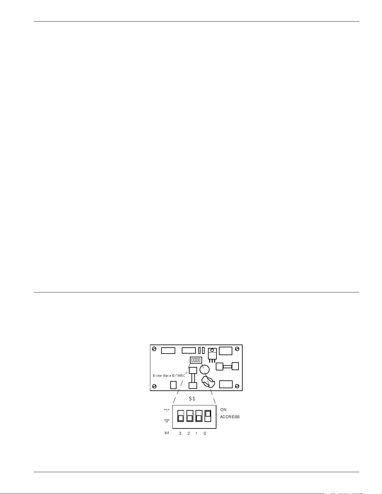
Your next step is to setup an address for each Exciter by using the S1 slide switch on
the EXT95SC board, as shown in Figure 5-2 below.
Exciter S lav e EXT95SC
S1
"1"
"0"
bit
3210
Figure 5-2: Setting Up the Exciter’s Address
ON
ADDR ESS
Configurati on and Oper ation 5- 5
Page 44
LF Transmitter Output
The addresses must be sequential between 1 and 14. For example, if there are 4
Exciters, they must be assigned addresses 1, 2, 3, and 4. Use the S1 switch to set the
address to binary format. For example, in binary format:
• address 1 is 0001
• address 2 is 0010
• address 3 is 0011
• address 4 is 0100
If the switch is in the ON position, the bit is set to 1. Otherwise, the bit is set to 0.
Note Addresses 0000
LF Transmitter Output
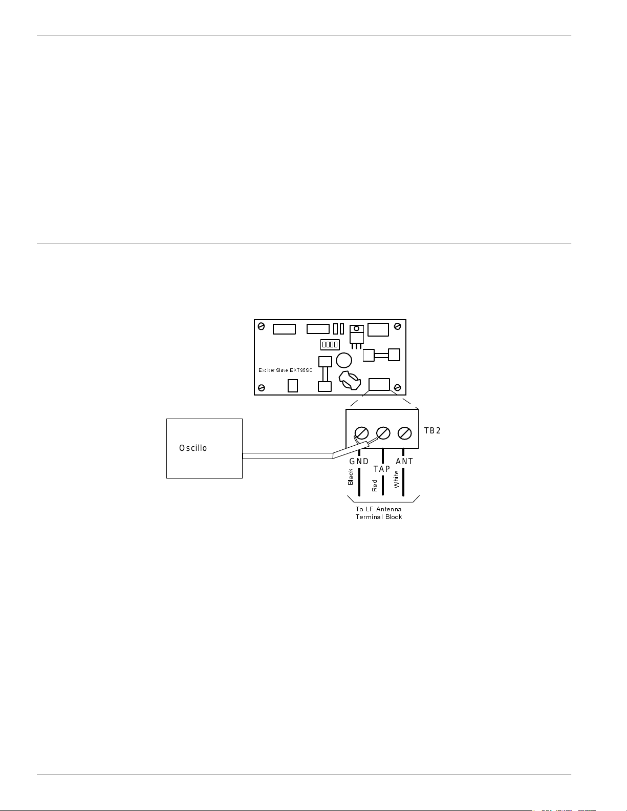
To check the LF signal, refer to Figure 5-3 below, and do the following:
2
2
2
2
and 11112 are reserved for special modes of operation.
2
Exciter Slave EXT95SC
TB2
Oscilloscope
TAP
Red
ANT
White
Figure 5-3: LF Signa l Meas ure me nt
GND
Black
To LF Antenna
Te rmi na l Blo ck
1. Connect the power to the Exciter.
2. Check the current parameter settings for the excitation mode and write down the
value of the following parameters: RCS, RES, REM, RET, HCC, HCS, HE0, and
HE1.
Note To determine the value of a parameter, for example, HE1, type the command:
HE1 <Enter>
5-6 Co nf iguratio n and Opera ti on
Page 45

LF Transmitter Output
The Reader will respond with the parameter value, for example,
HE1=6
where 6 is the value for the HE1 parameter.
3. Set the Continuous DC Mode type of execution, by typing:
RCS=N <Enter>
RES=N <Enter>
REM=C <Enter>
RET=D <Enter>
Note If a parameter already has the wanted value (determined in Step 2), you do not have
to reset it.
4. Turn on the excitation field, by typing:
B <Enter>
Check the TAP voltage [V
] at the terminal block TB2 on the EXT95SC board
TAP
(see Figure 5-3) using an oscilloscope. The signal must be a continuous
unmodulated carrier of 128.25 kHz with a peak-to-peak amplitude of
V
= 100 ± 20 Vpp.
TAP
Note When more than one Exciter 95 is used to create a wider excitation zone, a magnetic
coupling can appear. The phenomenon is explained in Chapter 4, Setup Guidelines in
the 95 Series RFID System Technical Guide. The coupling generates an unwanted
amplitude modulation with a frequency of several Hertz, the modulation depth
depending directly on the coupling. The installer has to monitor the TAP signal and
adjust the position of the E95 frames to obtain a minimum unwanted modulation
depth. The installer can increase the distance between frames, level the frames in the
same plane, or place the frames with the shorter sides (1m) in parallel. The minimum
amplitude of V
due to unwanted modulation must be larger than 60Vpp.
TAP
5. Turn off the excitation field, by typing:
C<Enter>
The TAP voltage amplitude should be zero.
6. Turn on the LF field again, by typing:
B <Enter>
The TAP voltage signal should have the same value as measured in Step 4.
7. Set the wanted excitation mode.
To set a specific excitation mode, refer to Appendix C, Excitation Modes. If you
want to return to the initial excitation mode as determined in Step 2, you have to
restore the values of the parameters modified in Step 3.
Configurati on and Oper ation 5- 7
Page 46

Configuring the Reader
For example, Lyngsoe recommends the following parameter values for the
Conditional Switching AC mode (CSAC) for the IPC installation:
RCS=Y; RES=Y; REM=C; RET=A; HCC=8; HCS=7; HE0=18; HE1=6
These parameters all have the default values.
8. Check the excitation field pattern as set in Step 7, by monitoring the TAP voltage.
For example, if the IPC’s CSAC mode was set and the Reader did not receive a
valid message, the TAP voltage has the following repetitive pattern: a carrier of
128.25 kHz modulated ON/OFF with 610Hz for 60 ms, followed by no signal for
180 ms.
9. Save the excitation mode set in Step 7, by typing:
:CON FIG:S TORE <Enter>
:RESET <Enter>
10. Check the parameter values set in Step 7 again.
11. Check the auto-diagnostic feature, by typing:
:DAR=Y <Enter>
:TEST:EXCITER k <Enter>
where k is the decimal address (1, 2, 3, ...) of the Exciter that you want to test.
The response should be 00, followed by a number (between IP-2 and IP) of
messages from the Test Tag.
12. Turn off the excitation field again, by typing:
C<Enter>
13. Check the auto-diagnostic feature, by typing:
:TEST:EXCITER k <Enter>
The response should be C9.
14. Repeat Steps 1 to 13 (inclusive) for each Exciter that is connected to the Reader.
Configuring the Reader
The Reader’s basic configuration covers the following group of parameters:
5-8 Co nf iguratio n an d Op er a tion
• Data buffering/reporting configuration - Group D parameters
• Hardware configuration - Group H parameters
• Instrument generic configuration - Group I parameters
• Tag data reading configuration - Group R parameters
For more information on these parameters, see the 95 Series RFID System Reference
Guide and the 95 Series RFID System Technical Guide.
Page 47

Note You can set these parameters for each particular application to optimize the
functionality of the Reader and the RFID System.
Settin g U p th e Ca rr i e r Th resho ld
Warning Before starting this procedure, you have to enable the auto-report and set the data
report in ASCII format, by typing the following:
DAR=Y<Enter>
DHX=N<Enter>
To setup the Reader’s carrier threshold, do the following:
1. Switch off the excitation field, by typing:
C<Enter>
2. Set the Receiver’s signal-to-noise ratio, by typing:
RSS=10<Enter>
Setting Up the Carrier Threshold
Note You can set other values for the RSS parameter. Lyngsoe recommends using a value
between 10 and 20 for the RSS parameter.
3. If you are using Diversity, enable it by typing:
HAD=Y<Enter>
Ensure that both UHF antennas are connected. If you are not using Diversity,
disable it by typing:
HAD=N<Enter>
Ensure that only
4. Check the noise level on the UHF channel, by typing:
HNL<Enter>
The HNL value should be between -107 to -95dBm.
If the HNL value is higher than -95dBm, check if there are unwanted
transmissions on the UHF channel (433.9 MHz). Pay special attention to
Transponders or Exciters in close proximity to the Reader; these can accidentally
transmit data that can be received by the Reader.
the right UHF antenna is selected (see the HAS parameter).
If the HNL value is lower than -105dBm, check its value without the UHF
antennas attached. The difference between these two readings must be greater
than 3dB.
Configurati on and Oper ation 5- 9
Page 48

Setting Up the Carrier Threshold
Note If the Reader resets itself, repeat the procedure from Step 1.
IMPORTANT * For a normal setup, the value of (HNL+RSS) must be less than - 85 dBm.
5. Set the carrier threshold, by typing:
S <Enter>
or
:CONFIG:THRESHOLD<Enter>
6. Monitor the DATA LED for at least 10 seconds. The LED must not flicker. If it
does flicker occasionally, increment the RSS parameter value by one. Go to Step 5.
* If the noise level is higher than -95 dBm, disconnect the UHF antennas from the
Reader, and check whether the HNL value drops below -107 dBm. If this occurs, it
means that there is unwanted transmission on the UHF channel. To correct this
situation, refer to Chapter 4, Setup Guidelines in the 95 Series RFID System
Technical Guide.
7. Place your Test Transponder T95 1-2 m away from an Exciter that is controlled by
the Reader you are configuring. For more information about identification zones
and the Test Transponders, refer to Chapter 4, Setup Guidelines in the 95 Series
RFID System Technical Guide.
8. Start the excitation field, by typing:
B<Enter>
9. Verify that the DATA LED is flickering, and check whether the Test Transponder’s
messages are displayed on the PC’s screen.
If data is not displayed, check the Reader’s parameter configuration, and follows
the troubleshooting instructions in Chapter 7, Troubleshooting.
If the number of displayed messages is below n=IP-2, check the carrier threshold
and try to adjust it again. Go to Step 1.
10. Remove the Test Transponder from the field and make sure that it is no longer
transmitting by ensuring that the DATA LED is not flickering.
5-10 Configuration and Operation
Page 49

Setting Up th e Exc it er’ s Test- T ag
Setting Up the Exciter’s Test-Tag
To set up the Exciter’s Test-Tag, do the following:
1. Set the parameters you want for the Test-Tag using the Group W parameters.
Example For an IPC application, you have to program the following parameters, by typing:
WDR=4 <Enter>
WEC=Y <Enter>
WEN=N <Enter>
WHF=N <Enter>
WID=0 <Enter>
WIP=15 <Enter>
WL T=Y <Enter>
WRC=0 <Enter>
WRS=0 <Enter>
WSD=200 <Enter>
WSM=Y <Enter>
WTF=Y <Enter>
WTS=N <Enter>
WWP=Y <Enter>
WUD=$43FE
nnrrkk
<Enter>
where:
nn is the PC’s address. If PC’s address is 1, or there is only one PC/site, nn=01.
rr is the Reader’s address. If Reader’s address is 1, rr = 01.
kk is the Exciter ’s address. If the Exciter ’s address is 1, kk = 01.
2. Turn off the LF field, by typing:
C<Enter>
3. Program the Exciter Test-Tag, by typing:
:TAG:MATCH:EXCITER k<Enter>
where k is the address of the Exciter you want to program.
If the response is not 00, the Exciter is not programmed. Repeat this command
several times, waiting at least 3 seconds between retries.
Note If you cannot program the Test Tag, see Chapter 7, Troubleshooting.
4. Turn on the LF field, by typing:
B<Enter>
5. Test the Exciter Test-Tag, by typing:
:TEST:EXCITER k<Enter>
where k is the address of the Exciter you want to test. The correct response is 00,
followed by a number of messages between IP-2 and IP. If less messages are
Configuration and Operation 5-11
Page 50

Setting Up the Real Time Clock
received, verify whether the UHF channel is jammed or replace the EXT95SC
board.
Note If you do not see the expected number of messages on your PC, (13-15 messages for an
IPC site), see Chapter 7, Troubleshooting and check the following parameters:
DAR=Y; DCI=0, DRI=0
6. Repeat Steps 1 to 5 for each Exciter that is connected to the Reader.
Setting Up the Real Time Clock
You can set the Reader’s date and time by using the IUT parameter. For more
information on setting up the Real Time Clock, refer to the 95 Series RFID System
Reference Guide.
Example For an IPC application, you should set the IUT parameter to GMT time. To set it, type:
IUT=YYMMDDhhmmZ<Enter>
where YYMMDDhhmm is the year, month, day, hour, and minute respectively.
Configuring the Reader’s Application Parameters
You can configure the Reader’s application parameters by setting the appropriate
values for the parameters in the following groups:
• Data buffering/reporting configuration (D)
• Hardware configuration (H)
• Instrument generic configuration (I)
• Tag data reading/excitation configuration (R)
• Serial communication configuration (S)
For example, for an IPC application, do the following:
1. Set the data filtration on the Reader, by typing:
DCI=10 <Enter>
DRI=30 <Enter>
2. Set the reported data format as ANS.1 format, by typing:
DHX=Y <Enter>
5-12 Configuration and Operation
3. Set the Tag data character count, by typing:
RCC=5 <Enter>
4. Leave the default values for the other parameters.
Page 51

Configuring the Reader’s Network Parameters
To configure the Reader’s network parameters, do the following:
1. Set the reporting mode, by typing:
DAR=N<Enter>.
2. Set the Reader’s address, by typing:
IAD=r<Enter>
where r is the Reader’s address. The lowest value for this address is 1. For
example, if there are 4 Readers in a network, they must be assigned the following
addresses 1, 2, 3 and 4.
Storing the Reader’s Configuration
Configuring the Reader’s Network Parameters
To store the Reader’s configuration, do the following:
1. Store the Reader’s parameters, by typing:
:CONFIG:STORE<Enter>
2. Reset the Reader, by typing:
:RESET<Enter>
Note The :CONFIG:STORE command stores the current Reader’s configuration in the non-
volatile memory.
The :RESET command updates the contents of the working memory from the non-
volatile memory.
3. Check whether the Reader is operating properly, by typing:
@r IVN<Enter>
where r is the Reader’s address. The Reader must respond with its software
version number.
Configuration and Operation 5-13
Page 52

Reader - Final Setup
Reader - Final Setup
To verify whether the Reader is responding, do the following:
1. Disconnect the PC from the Reader (See Figure 5-1 on page 5-2).
2. Set all jumpers (J1-J4) placed on the Motherboard MBD95 according to the type of
communication line used for the network. For more information on
communication lines used by the Reader R95, refer to Chapter 2, Reader R95
Installation and Connections.
3. Verify the connections between the Reader and the rest of the equipment (shorts,
loose connections, etc.)
4. Close the Reader’s enclosure.
95 Series R F ID Sy stem - Final Test
IMPORTANT * These tests must be done after all Readers and the Main PC are connected to the
network according to the site documentation.
* To communicate with the Reader, either use a terminal emulation program, such
as HyperTerminal or Procomm in Windows95, or the dedicated service module of
the application software running on the Main PC.
* All commands to the Reader must include the address field @r where r is the
Reader’s address (an integer followed by a blank).
You must repeat the following procedure for each Reader that is connected to the Main
PC.
For the final test, do the following:
1. Verify that the Reader is communicating with the Main PC, by typing:
@r IVN <Enter>
where r is the Reader’s address. The Reader must respond with the software’s
version number.
2. Set up the Carrier Threshold for the Reader as follows:
a) Switch on the excitation field, by typing:
5-14 Configuration and Operation
@r B <Enter>
b) Check the noise level, by typing:
@r HNL<Enter>
Page 53

95 Series RFID System - Final Test
If there is no unwanted transmission on the UHF channel, the Reader must
respond with a value lower than -95dBm for the HNL parameter. If not, refer to
Setting Up the Carrier Threshold on page 5-9.
c) Check and record the value for the existing Reader’s Carrier Threshold level, by
typing:
@r HTL<Enter>
The Reader should respond with the value for this parameter. For example,
HTL=95.
d) If the HNL level measured in Step b is lower than -95dBm, set the Reader’s
Carrier Threshold level again, by typing:
@r S<Enter>
or
@r :CONFIG:THRESHOLD<Enter>
The Carrier Threshold level setting is correct if the new HNL level displayed is
smaller than or equal to the level displayed in Step c. If not, check for unwanted
transmission on the UHF channel. You should also refer to Chapter 4, Setup
Guidelines in the 95 Series RFID System Technical Guide.
3. Verify that an Exciter that is controlled by a Reader communicates with the Main
PC:
a) Delete all Tag records from the Reader’s buffer, by typing:
@r :DATA:PURGE<Enter>
b) Confirm that the Reader’s buffer is empty, by typing:
@r D<Enter>
or
@r :DATA:REPORT<Enter>
The Reader must report a Null value.
Note For an IPC application, the data structure conforms to the ANS.1 standard. If the
Reader’s buffer is empty, the Reader sends a Null value of $0500. In ASCII format,
the Null value is { }.
c) Switch on the LF field, by typing:
@r B<Enter>
d) Send a Test Exciter command, by typing:
@r :TEST:EXCITER k<Enter>
where r is the Reader’s address and k is the Exciter’s address. The correct
Exciter’s response is 00.
Configuration and Operation 5-15
Page 54

95 Series RFID System - Final Test
Note For an IPC application, the Reader’s Tag Record Buffer contains 13-15 identical
e) Check the received messages, by typing:
@r D<Enter>
or
@r :DATA:REPORT<Enter>
The Reader must respond with the oldest record sent by the Exciter k’s Test-Tag,
in the format set by the DHX parameter. For more information on this parameter,
refer to the 95 Series RFID System Reference Guide.
messages sent by the Exciter k’s Test Tag in ANS.1 format. To read all messages, you
have to repeat the commands:
@r D<Enter>
@r E<Enter>
until you get the Null value $0500.
f) Empty the Reader’s Tag record buffer, by typing:
@r :DATA:PURGE<Enter>
g) Confirm that the Reader’s buffer is empty, by typing:
@r D<Enter> or @r :DATA:REPORT<Enter>
The Reader must report the Null value ($0500) in ANS.1 format.
4. Repeat Step 3 for all Exciters controlled by the Reader r.
5. Repeat Steps 1 to 4 for all Readers that are connected to the same PC.
5-16 Configuration and Operation
Page 55
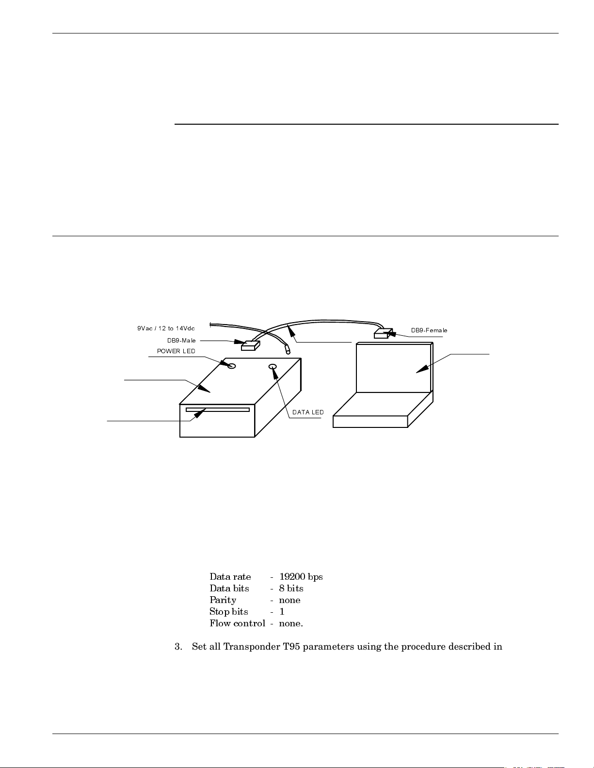
Programming and Testing the Transponder T95
This chapter explains how to setup a site and gives the procedure for programming
the Transponders T95. This chapter does not, however, explain how to choose
parameter values. For more information on configuring the Transponder 95, see the
95 Series RFID System Reference Guide.
Setting Up the Programming Site
Setup the programming site, as shown in Figure 6-1:
Setting Up the Pr og ram m in g Site
Chapter 6
Power Supply
9Vac / 12 to 14Vdc
DB9-Male
POWER LED
Programmer PGM95
Slot for T95
1. Install Lyngsoe’s T95 Programming Software, Version 2.00 or later on your PC.
2. The recommended configuration for the PC’s COM port is:
RS232 Cable
DAT A LED
Figure 6-1: Programming Site
DB9-Female
PC or Laptop
For more information on the installation, see the Readme.txt on the installation
diskette.
Data rate - 19200 bps
Data bits - 8 bits
Parity - none
Stop bits - 1
Flow control - none.
3. Set all Transponder T95 parameters using the procedure described in the
Readme.txt file.
Programming and Testing the Transponder T95 6-1
Page 56

Programming Procedures
4. Power-up the Programmer PGM95 from an AC power supply 9Vac + 10%, 50/60
Hz, or a DC power supply 11 to 14 Vdc. The maximum power supply is 0.5A.
Programming Proc edures
Place the Transponder T95 inside the special slot of the PGM95, with the component
side (battery side) down, and gently push it until it is inside the PGM95.
Using T95 Programming Software
Using a Terminal Emulation Program
To program the Transponder T95 using Lyngsoe’s T95 Programming Software, start
the software on your PC and follow the programming instructions in the Readme.txt
file.
To use a terminal emulation program, do the following:
1. Open a terminal emulation program, such as Hyperterminal (Windows 95), on your PC.
2. Set the PC’s COM configuration as described in the section Setting Up the
Reader/PC Connection in Chapter 5. Use this procedure to set and control the
communication between the PC and the Programmer PGM95 (PGM95
incorporates a Receiver CRM95).
3. Use the commands described in the 95 Series RFID System Reference Guide to set
the desired T95 configuration (Group W).
4. Program the T95 using the command: TAG: MATCH (shortcut M).
Confidence Tester TCT95
The Confidence Tester TCT95 is designed to qualify Transponder T95 programmed
with the IPC format, before they are seeded as probe letters into the mail-monitoring
process.
For more information on the Confidence Tester TCT95, see the Confidence Tester
TCT95 User’s Guide.
6-2 Programming and Testing the Transponder T95
Page 57

This chapter describes maintenance and troubleshooting procedures that you must
follow when using the 95 Series RFID System. These procedures complete the
troubleshooting information given in Chapter 5, Configuration and Operation, for the
initial system installation and configuration.
Preventive Maintenance
By using special commands, built-in Self Diagnostic circuits can check any part of the
system and report an error code, if necessary. Depending on the error code received,
the service technician will know the piece of hardware that is malfunctioning, and can
immediately take corrective action to remedy the situation.
Preventive M a i ntenan ce
Chapter 7
Troubleshooting
General Guidelines
All units have a warranty seal placed on their enclosures. Removal of this
seal will void the warranty.
Below is a list of some assumptions and guidelines:
1. The chapter assumes that repairs for any electronic assemblies are not made on
site. Unless otherwise stated, if a specified condition cannot be met, the electronic
assembly must replaced and returned to the manufacturer for repairs.
2. For a complete technical description of the 95 Series RFID System, refer to the
95 Series RFID System Technical Guide. For a detailed description of the
commands and parameters used to configure or to control the 95 Series RFID
System, refer to the 95 Series RFID System Reference Guide.
3. Information regarding the 95 Series RFID System’s configuration and operation is
described in Chapter 5, Configuration and Operation.
4. The locations of the DATA LED, the POWER LED, and the RESET button are
shown in Figure 5-1.
5. All the reference to commands are made assuming that the Reader’s address is 0.
Troubleshooting 7-1
Page 58
Genera l Guidelin es
The following table describes several possible failures for the 95 Series RFID System,
and the troubleshooting steps to correct them.
Problem Sympt om Probabl e Cause Solution
No communication
with a Reader.
Reader does not
respond to any
command.
1. Reader has an
incorrect address.
2. Faulty communication
line between the
Reader and PC.
1. Check whether the Reader responds
to commands using different
addresses, by typing the following:
@1 IVN<Enter>, @2 IVN<Enter>,
@3 IVN<Enter>. When a correct
address is sent, the Reader will
respond with its version number.
2. If, by using a specific address, you
are able to communicate with
Reader, use this address or change
the address to another value.
3. If after checking all possible
addresses (up to 31), you still cannot
communicate with the Reader, check
Probable Cause 2.
1. Open the Reader’s enclosure and
connect the PC directly to the
Reader using the RS-232
communication line. See Connecting
the RS-232 Communication Line on
page 2-2.
2. Switch off the Reader’s power supply
for at least 5 seconds, then perform
the steps in the Reader’s Power-up
Sequence on page 5-3.
3. If the Reader performs the power-on
test successfully, press the RESET
button once. Check whether the
DATA LED starts flashing at the
rate of 2 Hz.
4. Press the RESET button again.
Check whether the DATA LED stops
flashing.
5. Check whether the Reader is
responding to local commands by
typing: @r IVN, and pressing
<Enter>, where r is the Reader’s
address. The Reader must respond
with its version number.
7-2 Tr ou bleshooting
Page 59
Problem Symptom Probable Cause Solution
6. If you are able to communicate with
the Reader from the local PC, check
the integrity of the communication
line between the Reader and the PC.
7. After fixing the communication
line’s integrity, reconfigure the 95
Series RFID System and check
whether the Reader can
communicate with the PC.
8. If you cannot communicate with the
Reader (Step 5), check Probable
Cause 3.
General Guidelines
3. Reader lost its System
Code Identification
number and other
configuration
parameters.
1. Open the Reader’s enclosure and
connect the PC directly to the
Reader using the RS-232
communication line. See Connecting
the RS-232 Communication Line on
page 2-2.
2. Switch off the Reader’s power
supply for at least 5 seconds, then
perform the steps in the Reader’s
Power-up Sequence on page 5-3.
3. If the power-on test is successful,
the DATA LED should start flashing
continuously at the rate of 1.4 Hz.
4. Check the System Code number by
typing: ISC, and pressing <Enter>.
If the Reader responds with ISC =
0, setup the Reader’s System code
again by typing: ISC = your SC, and
pressing <Enter>.
5. If the Reader restored one of its
parameters to the default value, all
other parameters are also reset to
their default values. Check and
reset all the application- specific
parameters to their original values.
6. Check the HV0 and HV1 parameter
values. If these parameters have
default values 73 and 105
respectively, you must set them
again using the correct values from
Lyngsoe’s database.
Troubleshooting 7-3
Page 60
Genera l Guidelin es
Problem Symptom Probable Cause Solution
7. Store the Reader’s configuration by
following the steps in the section,
Storing the Reader’s Configuration
on page 5-13.
The HV0 and HV1 parameters are set
at the factory during the adjusting
procedure and recorded for each
Reader. If you know the Reader’s serial
number, Lyngsoe can supply you with
the values.
Note
Reader does not record
the Transponder’s
messages.
After the power-on
test is finished, the
sign-on message is
displayed on the
PC, but the DATA
LED is flashing
continuously at a
random rate.
An improper carrier
threshold was set, or
there is an unwanted
transmission on the UHF
channel.
1. Check whether the Reader is
receiving information that has been
accidentally transmitted from other
Transponders in its vicinity. If you
eliminate the unwanted
transmission, the DATA LED will
stop flickering.
2. Check whether an Exciter’s Test Tag
is transmitting accidentally. Switch
off the power supply of all Exciters
surrounding the Reader and monitor
the DATA LED. If the DATA LED
stops flickering, the unwanted
transmission originated in one of the
Exciters.
3. Run the procedure, 95 Series RFID
System - Final Test on page 5-14.
Step 2 - Set up the Carrier Threshold
for the Reader.
4. If the Reader reports a channel noise
level below -95dBm, but you are still
not receiving the Transponders’
messages, check the noise level
reported by the Reader with and
without UHF antennas connected. If
the noise level is identical or varies
slightly (±1 dBm), replace the
Reader.
7-4 Tr ou bleshooting
5. If the Reader reports a noise level
(HNL) above -95 dBm, the unwanted
transmission is on the UHF channel.
For procedures on eliminating the
unwanted transmission, refer to
Chapter 4, Setup Guidelines in the
95 Series RFID System Technical
Guide.
Page 61
Problem Symptom Probable Cause Solution
General Guidelines
After the power-on
test is finished, the
sign-on message is
displayed on the
PC, and the DATA
LED is flashing
only
when a
Tran sp o nder is
activated.
The configurations of the
Transponder and the
Reader do not match.
1. Using a Test Transponder TST95
that has been programmed for your
application, test the Reader’s
receiving capability.
2. If you can receive transmitted
messages from the TST95, the
Transponders are either not
correctly configured for your
application, or they are out of
specifications. Reprogram the
Transponders and check whether the
Reader can receive messages.
3. If you cannot receive transmitted
messages from the TST95, the
Reader has an incorrect
configuration. Go to Steps 4 and 5.
4. Check whether the DAR parameter
and the Group R parameters are set
according to the application’s
specifications.
5. With this new set of parameters,
check whether the Reader can
receive transmitted messages from
the TST95. If the Reader can receive
the messages, save its configuration,
by typing the following commands
and pressing <Enter> after each
command: :CONFIG:STORE,
:RESET.
After the power-on
test is finished, the
sign-on message is
displayed on the
PC, but the DATA
LED is not flashing
when a
Tran sp o nder is
activated.
The carrier threshold
value is too high.
1. Run the procedure, 95 Series RFID
System - Final Test on page 5-14.
Step 2 - Set up the Carrier Threshold
for the Reader.
2. If the Reader reports a channel noise
level below -95dBm, but you are still
not receiving the Transponders’
messages, check the noise level
reported by the Reader with and
without connected UHF antennas. If
the noise level is identical or varies
slightly (±1 dBm), replace the
Reader.
3. Check the HNL and RSS parameter
values.
Troubleshooting 7-5
Page 62
Genera l Guidelin es
Problem Symptom Probable Cause Solution
4. If the value of (HNL + RSS) is higher
than -85dBm, there is either an
unwanted transmission on the UHF
channel, or the value of the RSS
parameter is too high. The value
for the RSS parameter must be
between 10 and 20.
5. Check whether there are
Transponders or an Exciter’s Test
Tag in the immediate vicinity that
transmit messages accidentally.
6. Run the procedure, Setting Up the
Carrier Threshold again, and
monitor the value for the HNL
parameter after each setup.
7. For procedures on eliminating the
unwanted transmission, refer to
Chapter 4, Setup Guidelines in the
95 Series RFID System Technical
Guide.
Reader does not record
all transmitted
messages.
Reader does not
record all
transmitted
messages by the
Tran sp o nder.
The receiving zone is too
small because of either a
high carrier threshold, or
there is random
interference on the UHF
channel.
1. Run the procedure, 95 Series RFID
System - Final Test on page 5-14.
Step 2 - Set up the Carrier Threshold
for the Reader.
2. If you observe a random variation of
noise and interference on the UHF
channel, either increase the value of
the RSS parameter, or set the HTL
parameter to a higher value than the
one that was automatically set by
the Reader.
3. If the receiving zone is too small
after you set a higher carrier
threshold, follow the setup
guidelines recommended in Chapter
4, Setup Guidelines in the 95 Series
RFID System Technical Guide.
Note
A UHF channel is subject to random
noise and interference. The Reader
disregards the messages with data
errors. For an optimal channel, free of
interference and industrial noise, the
Reader must be able to receive all
messages transmitted by a single
Transponder placed in its reading
7-6 Tr ou bleshooting
Page 63
Problem Symptom Probable Cause Solution
range. When using multiple
Transponders, some messages are lost
due to the inherent collision between
them.
General Guidelines
Time-out error.
(At the command
:TEST:EXCITER k, the
response is 00, but the
Main PC does not
receive a message, or a
correct message from
the Test Tag of the
Exciter k after a
predetermined period
of time).
DATA LED is
flickering, the
Reader’s Tag
Record Buffer
contains messages
from the Test Tag.
DATA LED is
flickering, but the
Reader’s Tag
Record Buffer is
empty.
Test tag was incorrectly
programmed.
Test tag was incorrectly
programmed.
1. Query the Test Tag programming
parameters using
:TAG:QUERY:EXCITER k.
2. Check the value of all group T
parameters.
3. Correct the values using the group
W parameters.
4. Reprogram the Test TAg using the
command :TAG:MATCH:EXCITER k.
1. Query the Test Tag programming
parameters using
:TAG:QUERY:EXCITER k.
2. Check the value of all group T
parameters.
3. Correct the values using the group
W parameters.
4. Reprogram the Test Tag using the
command :TAG:MATCH:EXCITER k.
DATA LED is not
flickering
Exciter’s Test Tag is
placed beyond the limits
of the receiving zone, or
there is a random
interference on the UHF
channel, or the Test Tag
is out of specifications.
1. Run the procedure, 95 Series RFID
System - Final Test on page 5-14.
Step 2 - Set up the Carrier
Threshold for the Reader.
2. Check the RF level of the messages
received from the Test Tag; it must
be higher than (RSS+HNL+3)dBm,
that means 3dB above the carrier
threshold value.
Note
The Reader reports the RF level of the
received message only if the parameter
DLI=Y.
3. If the RF level of the Test Tag’s
received messa ges is lower than
-85dBm, either reposition the
Reader or Exciter, or use a higher
gain UHF antenna for the Reader.
Troubleshooting 7-7
Page 64

Genera l Guidelin es
Problem Symptom Probable Cause Solution
Excitation field
generated by the
Exciter is below
Specifications.
The Exciter responds
with C9 at the SelfDiagnostic Procedure.
LF Transmitter
Output is low
(V
< 80 Vpp).
TAP
Exciter k responds
with C9 at the
command:
:TEST:EXCITER k
sent by the Main
PC (k is the
Exciter’s address).
The LF antenna loop has
a loose connection, or the
LF antenna is detuned
by a metallic object.
A faulty Exciter or a
loose connection in the
power cable or
communication cable
between the Reader and
the Exciter.
1. Check whether the LF antenna
wires are connected to the terminal
block (See LF Antenna Connections
on page 3-3).
2. Check the 3-wire connection
between the LF antenna terminal
block and the EXT95SC assembly
(terminal block TB2).
3. Check whether the recommended
setup guidelines for the Exciter’s
location are met. Pay special
attention to metallic surfaces
surrounding the Exciter, shortcircuit loops, and the spacing
between adjacent Exciters.
1. Check the power cable and the
communication cable between the
Reader and the Exciter.
2. Check the Exciter’s address setting.
3. Check the LF Transmitter’s output.
(See LF Antenna Connections on
page 3-3).
A large magnetic
coupling between 2
adjacent Exciter E95
1. Check the Exciter’s TAP voltage.
(See LF Transmitter Output on page
5-6).
frames
2. Reposition the E95 frames to
minimize the unwanted modulation;
The LF antenna is
the amplitude of V
TAP min
1. Check the Exciter’s V
TAP
.
> 60 Vpp.
detuned by metallic
objects that are in close
proximity.
2. Reposition the E95 frames to
minimize the detuning;
the amplitude of V
> 80 Vpp.
TAP
7-8 Tr ou bleshooting
Page 65

Transponder T95C
Appendix A
Specifications
This appendix gives technical specifications for the Transponder T95, the Reader R95,
the Exciter E95, and the AC Source TRM95. It also gives information on system
performances and special features.
Transponder T95C
LF Recei ver • Configuration: Direct detection for 125.0 kHz signals modulated On/Off (OOK)
with 610 Hz.
• Carrier Frequency (125.0 kHz) Bandwidth @3dB:12 to 18 kHz.
• Modulation Frequency (600 kHz) Bandwidth @ 3dBm: 80 to 200 Hz.
• Sensitivity: better than H = 10mA/m[80 dBµA/m] or B=12.6nT in specific test
conditions.
UHF Transmitter • Carrier Frequency, nominal: 433.92 MHz ±50 kHz, stabilized by a SAW resonator.
• Carrier Frequency, max. variation: ±100 kHz, temperature and aging
• Modulation Type: Frequency-Shift Keying (FSK).
• Total Frequency Deviation, nominal: 15 ±3 kHz.
• Total Frequency Deviation, max. variation: 8 to 40 kHz.
• Radiated Power (ERP): less than 10 µW.
• Data Rate: 19.2 or 38.4 kbps.
Excitation Signal The Transponder is only
duration of at least 50ms.
Programming • Mode: optical.
• Data Rate: 1.2 kbps.
• Parameters: see the 95 Series RFID System Reference Guide.
awaken by signals accepted by the LF Receiver that have a
Writing and
Transmittin g Data
Message Format For more information, see Appendix B, Transponder T95 Messages.
Power Supply 3 V/150 mAh, lithium cell battery.
Asynchronous, NRZ, using a specially developed protocol.
Speci f ic ations A - 1
Page 66

Reader R95
Power
Consumption
Transponder
Lifetime
Environmental
Operation
Temperature
Storage
Temperature
Relative
Humidity
Mechanical • Dimensions, max
Maximum 3 µA in sleep mode; 2.5mA in transmission mode.
More than 5 years under normal use (1000 transmission/year).
- 20°C to +55°C.
- 40°C to +70°C.
Maximum 95%, non-condensing at +40°C
Length: 143.0 mm
Width: 107 mm
Height: max. 2.8 mm
• Weight: max 12 g
• Survives at least 1000 times through the automatic mail sorting machine.
Approvals Approved under I-ETS 300 220, I-ETS 300 330, RS-210 and FCC Part 15.
Reader R95
Configuration Superheterodyne receiver for 433.92 MHz signals modulated FSK.
Sensitivity Better than -105 dBm at 12 dB SINAD for 1 kHz modulation and 15 kHz total
deviation.
Successful
Message Ratio
(Throughput)
Object Sensor
Input
Relay Driving
Capabilities
Better than 98% for any of the following conditions:
• RF Input Signal: -90 dBm to -10 dBm
• Frequency Range: 433.92 MHz ± 75 kHz.
• Total Frequency Deviation: 7 to 45 kHz.
• Data Rate: 19.2, or 38.4 kbps.
• Voltage limits: -0.5 to 5.5V
• Current: max 50µA
• Max. Switching Current: 1A
• Max. Switched Voltage: 150Vdc or 300Vac
• Max. Switched Power: 30 W or 60 VA
• UL Rating: 1A @ 30Vdc
0.5A @ 120Vdc
A-2 Specifications
Page 67

Reader R95
Additional
Features
• RF antenna diversity.
• RF input signal level measurement. This information is attached to every received
message.
• Programmable carrier threshold. Only input RF signals above this threshold are
processed.
• Real time clock: a time stamp (Month/Day/Hour/Minute) can be added to every
received message.
• Reads data with or without error checking and encryption in hexadecimal or
ASCII format.
• Received messages can be filtrated by time, RF signal level, system code, and data
content.
• Stores over 50 kbytes of received messages in an internal buffer.
• Interfaces with a PC through the RS-232 or RS-485 interface. The RS-485 can be
configured for half-duplex (2 wires) or full-duplex (4 wires).
• Controls up to 15 Exciters E95 through a dedicated RS-485 interface.
• Reader’s firmware can be upgraded using the serial interface.
Power Supply 12Vac ±10%, 50/60 Hz, or 13 to 16 Vdc.
Power
Maximum 0.3 A.
Consumption
Environmental
Operation
- 20°C to +55°C.
Temperature
Storage
- 40°C to +70°C.
Temperature
Relative
Maximum 95%, non-condensing at +40°C.
Humidity
Mechanical • Dimensions (without UHF antennas)
Length: 250 ± 5 mm
Width: 210 ± 5 mm
Height: 100 ± 5 mm
•Weight: max 4 kg
Approvals Approved under I-ETS 300-220, I-ETS 300-330, RS-210 and FCC Part 15.
Speci f ic ations A - 3
Page 68

Exciter E95
Exciter E95
LF Transmitter • Carrier Frequency: 125.0 kHz, quartz crystal generated.
• Modulation type: On/Off Keying (OOK).
• Modulation Frequency: 600 ±10 Hz.
• Carrier and modulation frequency tolerance: ± 50 ppm (± 6.6 kHz).
• Carrier and modulation frequency stability: better than 100 ppm (± 13.2 kHz) over
the temperature range.
• Carrier and modulation frequency aging: maximum 3 ppm/year (0.4 Hz/year).
• Maximum radiated E-field at 10 m: 105 ±6 dB µV/m.
Additional
Features
Power Supply 22 Vac ±10%, 50/60 Hz; or 23 - 28 Vdc.
Power
Consumption
Environmental
Operation
Temperature
Storage
Temperature
• Exciter E95 incorporates a UHF transmitter that simulates the Transponder T95
to check the Reader ’s capability.
• Test Transponder can be programmed and activated from the main PC.
• Self diagnostic for LF-Transmitter output level.
• Self diagnostic for power supply voltage level.
• Output relay driving
• Input Object Sensor
Maximum 0.5 A.
- 20°C to +55°C.
- 40°C to +70°C.
Relative
Humidity
Mechanical • Dimensions
A-4 Specifications
Maximum 95%, non-condensing at +40°C.
Length: 2060 ± 10 mm
Width: 1000 ± 10 mm
Height: 75 ± 5 mm
• Weight: max 5.5 kg
Page 69

Approvals Approved under I-ETS 300 330, I-ETS 300 220, RSS-210 and FCC Part 15.
Power Supply TRM95
Input • AC line voltage:120Vac - model TRM95/120V
230Vac - model TRM95/230V
• Ratings: Model TRM95/120V - 0.7A, 60 Hz
Model TRM95/230V - 0.35A, 50 Hz
• Voltage tolerance: ±10%
• Fusing: Type T (“Slo-Blo”), 5x20mm; 1A for TRM95/120V; 0.5A for TRM95/230V
Output • Dual: 12 Vac/1A, 22Vac/2A
• Frequency: 50/60Hz
• Voltage tolerance: ±10%
Power Supply TRM95
Environmental
Operation
Temperature
Storage
Temperature
Relative
Humidity
Mechanical • Dimensions
Approvals Approved under CSA, UL, and CE.
- 30°C to +50°C.
- 40°C to +70°C.
Maximum 95%, non-condensing at +40°C.
Length: 300 ± 5 mm
Width: 168 ± 5 mm
Height: 132 ± 5 mm
System P erformance
Excitation Range Larger than 4.0 m in open space conditions.
Reading Range Larger than 20.0 m in open space conditions.
Identification
Capability
Transponders can be identified (excited and recorded) when they are placed inside
standard mail trays and bags, or collated on rollercages when they are moving
through the RFID system at the normal operational speed (less than 5 m/s).
Speci f ic ations A - 5
Page 70

System Perform an ce
Readers can simultaneously identify up to 15 Transponders present in the excitation
field. The level of accuracy is greater than 95%.
System Capacity Up to 31 Readers R95 can be connected through the RS-485 interface to the main PC.
Up to 15 Exciters E95 can be controlled by any Reader R95. More Exciters E95 can be
used to generate a specific shape for the excitation gate.
Self Testing
Capabilities
At the request of the main computer, the RFID System automatically reports the
status of the LF excitation field generated by each Exciter E95, and the receiving
capability of each Reader R95.
Object Sensor
An external object sensor device can switch the excitation field On and Off.
Monitoring
Driving Output A Single Pole Double Throw (SPDT) relay contact is available to drive external
devices. The relay is activated each time the Reader receives a correct message.
A-6 Specifications
Page 71
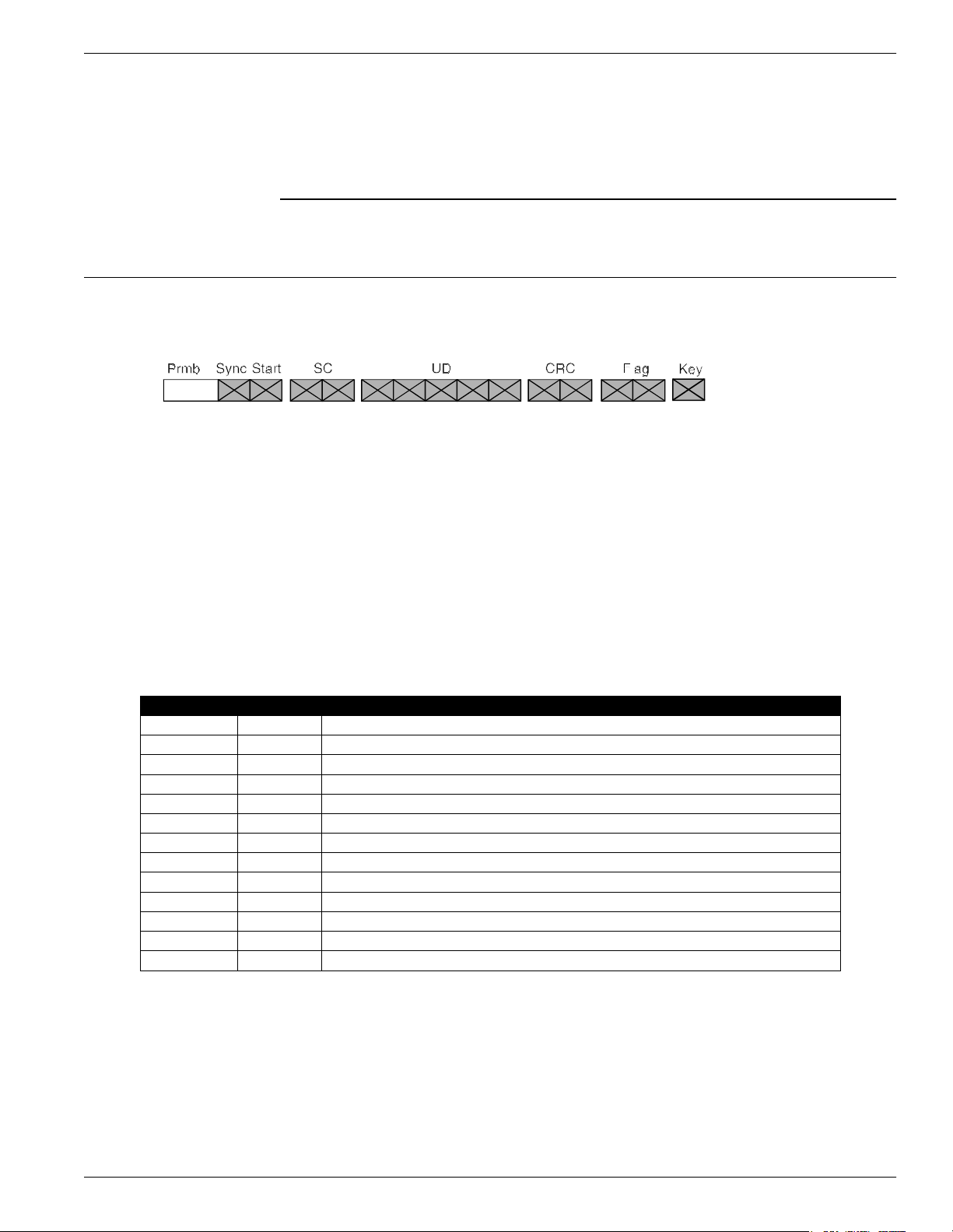
Message Format
Message Format
Appendix B
Transpon de r T 95 Messages
Each message has the following format
where:
Prmbl = 0.7 ms continue 1.
Sync = a string of 10 bits of “0101010101”; transmitted only if SM=Y.
Start = a string of 13 bits “0101010000111”; transmitted only if SM=Y.
SC = 2 bytes system code; transmitted only if TS=Y.
UD = user definable data; number of bytes is set by CC (1 to 32).
CRC = 2 bytes CRC; transmitted only if EC=Y.
Flag = 2 bytes message flags; transmitted only if TF=Y. It has 1 byte if HF=N and
2 bytes if HF=Y.
Key = 1 byte message key; transmitted only if EN=Y.
T95 Parameters The parameters that control the message transmission for T95 are shown in the table
below:
Parameter Range Description
DR 3,4 Data rate; DR3 = 19.2 kbps, DR4= 38.4 kbps
EC Y/N Standard error check transmitted
EN Y/N Data encryption available
HF Y/N Flags in hexadecimal
ID 0...200 Initial delay
IP 1...200 Initial number of messages transmitted after a valid execution
LT Y/ N Limit repeated transmissions
RC 0...255 Nu mber of extra mess ages tran smit t ed af ter IP during a continuous excitation
RS 0...255 Random seed
SD 1...220 Subsequent delay
SM Y/N Synchronous preamble transmitted
TF Y/N Transmit Flags
TS Y/N Transmit System Code
Total Transmission Time
After a valid excitation, the T95 transmits the initial number of messages defined by
the IP parameter, followed by an extra number of messages (up to the RC) for as long
as the excitation exists. Then it goes to sleep.
There is a random delay called InterMsgDelay that occurs between two consecutive
messages. This is implemented to ensure that the delay time does not repeat itself
before 32 messages have occurred.
Transponder T95 Messages B-1
Page 72

Message Format
The following is the method of evaluating the maximum transmission time for the
T95:
Number of bytes per message: TXBytes = SC + UD + CRC + Flag + Key
Number of bits per byte: BitsPerByte = 12 for DR4, and = 11 for DR3
Number of bits per message: TXBits = Sync + BitsPerByte*TXBytes
Bit duration: BitLen = 1/DR
Message length: MsLen = 0.0007 +TXBit*BitLen
Intermessage constant: InterMsgUnit = (UD + Flag)*0.0003066, for DR4;
= (UD + Flag)*0.0005657), for DR3
Intermessage delay: InterMsgDelay = [SD +RND(0…31)]*InterMsgUnit;
(RND - random value)
Maximum number of transmitted messages: NM = IP +RC; if LT = N
Total transmission time: TXTime = NM (MsLen +(NM-1) (InterMsgDelay)
The following tables present the maximum number of messages (NM) that can be
transmitted in five seconds, using different sets of parameters for the T95.
B-2 Transponder T95 Messages
Page 73
Message Format
SM = Y, T F = Y, HF = Y, TS = Y, EC = Y, EN = Y
M a x im u m a llow a b le n u mb e r o f mes s ag e s ( IP + R C ) th at c a n b e tra ns mitte d in 5 se c o n d s
135791113151719212325272931333537394143454749515355575961636567697173757779818385878991
261 236 220 202 192 175 167 158 147 140 134 130 122 116 111 107 104 101 98 94 90 87 84 82 79 77 75 73 72 70 69 67 66 65 62 61 59 58 57 55 54 53 52 51 50 492201 183 168 157 143 136 130 119 112 107 102 99 94 88 84 81 78 75 73 71 69 67 65 64 60 58 57 55 53 52 51 49 48 47 46 45 44 43 43 42 41 40 40 39 38 383165 148 137 129 116 108 103 99 92 86 81 77 74 72 69 67 65 61 59 56 54 52 51 49 48 46 45 44 43 42 41 40 39 39 38 37 36 36 35 34 34 33 33 31 31 304138 129 113 106 100 93 85 80 76 72 69 67 65 60 57 54 52 50 48 47 45 44 43 41 40 39 38 37 37 36 35 34 34 33 32 31 30 29 28 28 27 27 26 26 25 255118 107 101 92 83 78 73 70 67 65 59 55 53 50 48 46 45 43 42 40 39 38 37 36 35 35 34 33 31 30 29 29 28 27 26 26 25 25 24 23 23 22 22 22 21 216104 98 86 78 74 70 67 62 57 53 50 48 46 44 42 41 40 38 37 36 35 34 33 33 31 30 29 28 27 26 25 25 24 23 23 22 22 21 21 20 20 19 19 19 18 18
SD
1
CC
97 83 76 71 68 65 57 53 50 47 45 43 41 40 38 37 36 35 34 33 31 30 29 27 27 26 25 24 23 23 22 22 21 20 20 20 19 19 18 18 18 17 17 17 16 16882 75 70 66 60 54 50 47 45 43 41 39 38 36 35 34 33 31 30 28 27 26 25 24 23 23 22 21 21 20 20 19 19 18 18 17 17 17 16 16 16 15 15 15 15 14975 70 66 58 52 49 46 43 41 39 38 36 35 34 33 30 29 27 26 25 24 23 22 22 21 20 20 19 19 18 18 17 17 17 16 16 15 15 15 15 14 14 14 14 13 131071 66 58 52 48 45 42 40 38 37 35 34 33 30 29 27 26 25 24 23 22 21 20 20 19 19 18 18 17 17 16 16 15 15 15 14 14 14 14 13 13 13 13 12 12 121167 59 52 47 44 42 39 38 36 35 33 31 29 27 26 24 23 22 21 21 20 19 19 18 17 17 17 16 16 15 15 15 14 14 14 13 13 13 13 12 12 12 12 11 11 111265 52 47 44 41 39 37 36 34 33 30 28 26 25 23 22 21 20 20 19 18 18 17 17 16 16 15 15 14 14 14 13 13 13 13 12 12 12 12 11 11 11 11 11 10 101354 48 44 41 39 37 36 34 33 29 27 25 24 23 22 21 20 19 18 18 17 16 16 15 15 15 14 14 13 13 13 13 12 12 12 12 11 11 11 11 10 10 10 10 10 10145045423937363433292725232221201918181716161515141414131313121212111111111110101010109999
7
4743403836343329262423222019191817161615151414141313121212121111111110101010109999998
4441383634332926242321201918171716151514141413131212121111111110101010109999998888
4239373533302624222120191817161615151414131312121211111111101010109999998888888
40383634312724232120191817161515141413131212121111111110101010999998888888777
393735332825232120191817161515141413131212121111111010101099999888888877777
15
16
17
18
19
3836343026232120191817161514141313121212111111101010109999988888877777777
37353327242220191817161514141313121211111110101010999998888887777777766
363429252220191817161514141313121211111110101099999888888777777776666
35332723211918171615141413131212111111101010999988888877777776666666
3430252220181716151414131312121111101010109999888887777777666666666
33272321191816151514131312121111101010999988888777777766666666665
3325222018171615141313121211111010109999888887777776666666666555
30242119171615141313121211 11101010 99998888777777766666666655555
20
21
22
23
24
25
26
27
27222018171514141312121111 101010 9 99888887777776666666665555555
252119171615141312121111101010 9 9 98888877777766666666555555555
232018161514131312111111101099988888777776666666665555555555
22191716151413121211111010999888887777766666666555555555555
2118171514131312111110109999888877777666666665555555555544
28
29
30
31
32
DR= 4
Transponder T95 Messages B-3
Page 74

Message Format
SM = Y, TF = Y, HF = Y, TS = Y, EC = Y, EN = Y
SD
R= 3
B-4 Transponder T95 Messages
1 3 5 7 9 11 13 15 17 19 21 23 25 27 29 31 33 3537394143454749515355575961636567697173757779818385878991
CC
87 78 73 69 65 59 54 50 48 45 43 41 40 38 3 7 36 35 34 33 31 30 28 27 2 6 25 25 24 23 23 22 21 21 20 20 19 19 18 18 18 17 17 17 16 16 16 15473 68 65 56 51 47 45 42 40 39 37 36 35 33 3 2 30 28 27 26 25 24 23 22 2 1 21 20 19 19 18 18 18 17 17 16 16 16 15 15 15 14 14 14 14 13 13 13566 57 51 47 44 41 39 37 36 35 33 31 29 27 2 6 24 23 22 21 21 20 19 19 1 8 17 17 17 16 16 15 15 15 14 14 14 13 13 13 13 12 12 12 12 11 11 11654 48 44 41 39 37 36 34 33 29 27 26 24 23 2 2 21 20 19 18 18 17 17 16 1 6 15 15 14 14 14 13 13 13 12 12 12 12 11 11 11 11 11 10 10 1 0 10 1074743403836343329272523222120191817171616151514141313131212121211111111101010101099999984340373534312725232220191818171615151414131313121212111111111010101010999998888889403735332926242220191817161615141413131312121211111110101010999998888888777710373533292523211918171616151414131312121211111110101099999888888877777777113634292522201918171615141413131212111111101010999998888887777777666661234302522201817161514141313121211111010101099998888877777776666666661333252220181716151413131212111110101099998888877777776666666665551427232018171615141312121111111010 9 99988888777777666666666555555152420181716151413121211 11 101010 9 9 988887777776666666665555555551621191716141413121211 101010 9 9 9 8 8887777776666666655555555555517191716151413121111101010 9 9 9 8 8 877777766666665555555555544441818161514131211111010 9 9 9 8 8 8 8 7777766666665555555555544444419171514131211111010 9 9 9 8 8 8 7 7 77766666665555555555444444444201614131212111010 9 9 9 8 8 8 7 7 7 766666665555555555444444444442115141312111010 9 9 8 8 8 8 7 7 7 7 6666665555555554444444444444422141312111010 9 9 9 8 8 8 7 7 7 7 6 66666555555554444444444444443231312111110 9 9 9 8 8 7 7 7 7 6 6 6 66655555555544444444444444333241312111010 9 9 8 8 8 7 7 7 6 6 6 6 66555555554444444444444433333251211 1010 9 9 8 8 8 7 7 7 6 6 6 6 6 55555555444444444444443333333261211 10 9 9 8 8 8 7 7 7 6 6 6 6 6 5 555555544444444444443333333332711 1010 9 9 8 8 7 7 7 6 6 6 6 6 5 5 555555444444444444333333333332811 10 9 9 8 8 7 7 7 7 6 6 6 6 5 5 5 55554444444444443333333333333291010 9 8 8 8 7 7 7 6 6 6 6 5 5 5 5 555444444444444333333333333333010 9 9 8 8 7 7 7 6 6 6 6 5 5 5 5 5 554444444444433333333333333333110 9 8 8 7 7 7 6 6 6 6 6 5 5 5 5 5 54444444444433333333333333333
140131117 109103 98 90 84 79 75 72 70 67 65 61 58 55 53514948464544434241403938373636353434333231302929282827262107 100 91 82 77 73 69 66 62 57 54 51 49 47 4 5 43 42 41 39 38 37 36 35 3 4 34 33 31 30 29 28 27 27 26 25 25 24 23 23 22 22 21 21 21 20 20 20
3
1
Maximum allowable number of messages ( IP + RC ) that can be transmitted in 5 seconds
9 9 8 8 7 7 7 6 6 6 6 5 5 5 5 5 5 44444444443333333333333333333
32
Page 75

Message Format
1
6
7
9
4
9
6
4
4
5
8
1
9
3
8
5
3
3
4
7
1
6
7
4
8
2
5
3
5
2
3
9
4
4
8
7
1
Transm ission Tim e , sec
DR =4 SM =Y TF =Y HF =Y TS =Y EC =Y CC =5 EN =Y
0.591 0.629 0.668 0.706 0.745 0.784 0 .822 0.861 0.9 0 .938 0.977 1.015 1.054 1.093 1.131 1.17 1 .209 1.247 1.286 1.325 1.363 1.402 1.44 1.479 1.518 1.55
0.697 0.744 0.792 0.839 0.886 0.933 0.98 1.028 1.075 1 .122 1.169 1.216 1.264 1 .311 1.358 1.405 1.453 1 .5 1.547 1.594 1.641 1.689 1.736 1.783 1.83 1.87
0.795 0.851 0.907 0.962 1.018 1.074 1.13 1.186 1.241 1 .297 1.353 1.409 1.465 1.52 1.576 1.632 1.688 1.744 1.799 1.855 1.911 1.967 2.023 2 .078 2.134 2.1
0.884 0.949 1.013 1.078 1.142 1.206 1 .271 1.335 1.399 1.464 1.528 1.593 1.657 1 .721 1.786 1.85 1.915 1.979 2.043 2.108 2.172 2.236 2.301 2 .365 2.43 2.49
0.965 1.038 1.111 1.184 1.257 1.33 1 .403 1.476 1.549 1.622 1.695 1.768 1.841 1 .914 1.987 2.06 2.133 2.206 2.279 2.352 2.425 2.498 2.57 2.643 2.716 2.78
SD
10
12
RC+IP 1 3 5 7 9 11 13 15 17 19 2 1 23 25 27 29 31 33 35 37 39 41 43 45 47 49 5
14
16
18
1.037 1.119 1.2 1 .282 1.364 1.445 1.527 1.608 1.69 1 .771 1.853 1.934 2.016 2 .098 2.179 2.261 2.342 2.424 2.505 2.587 2.668 2.75 2.832 2.913 2.995 3.07
20
1.101 1.191 1.281 1.371 1.461 1.552 1 .642 1.732 1.822 1.912 2.002 2.092 2.183 2 .273 2.363 2.453 2.543 2.633 2.723 2.814 2.904 2.994 3.084 3 .174 3.264 3.35
22
1.156 1.255 1.353 1.452 1.551 1.65 1 .748 1.847 1.946 2.044 2.143 2.242 2.341 2 .439 2.538 2.637 2.736 2.834 2.933 3.032 3.13 3.229 3.328 3.427 3.525 3.62
24
1.202 1.31 1.417 1.524 1.632 1.739 1 .846 1.954 2.061 2.168 2.275 2.383 2.49 2.597 2.705 2.812 2.919 3.027 3.134 3.241 3.349 3.456 3.563 3.67 3.778 3.88
26
1.24 1.356 1.472 1 .588 1.704 1.82 1.936 2.051 2.167 2 .283 2.399 2.515 2.631 2.747 2.863 2.979 3 .095 3.21 3.326 3.442 3.558 3.674 3.79 3.906 4.022 4.1 3
28
1.269 1.394 1.518 1.643 1.767 1.892 2 .016 2.141 2.265 2.39 2.514 2.639 2.763 2 .888 3.012 3.137 3.261 3.386 3.51 3.635 3.759 3.884 4.008 4.132 4.257 4.38
30
1.219 1.348 1.477 1.606 1.734 1.863 1 .992 2.121 2.249 2.378 2.507 2.636 2.765 2 .893 3.022 3.151 3.28 3.408 3.537 3.666 3.795 3.924 4.052 4 .181 4.31 4.43
32
1.369 1.506 1.643 1.781 1.918 2.056 2 .193 2.33 2.468 2.605 2.742 2.88 3.017 3 .154 3.292 3.429 3.566 3.704 3.841 3.979 4.116 4.253 4.391 4.528 4.665 4.80
34
1.51 1.656 1.801 1 .947 2.093 2.239 2.385 2.531 2.677 2 .823 2.969 3.115 3.261 3.407 3.553 3.699 3 .845 3.991 4.137 4.282 4.428 4.574 4.72 4 .866 5.012 5.15
36
1.642 1.796 1.951 2.105 2.26 2.415 2 .569 2.724 2.878 3.033 3.187 3.342 3.496 3 .651 3.805 3.96 4.114 4.269 4.423 4.578 4.732 4.887 5.041 5.196 5.351 5.50
38
1.766 1.929 2.092 2.255 2.418 2.581 2 .744 2.907 3.07 3.234 3.397 3.56 3.723 3 .886 4.049 4.212 4.375 4.538 4.702 4.865 5.028 5.191 5.354 5.517 5.68 5.84
40
1.881 2.052 2.224 2.396 2.567 2.739 2 .911 3.083 3.254 3.426 3.598 3.769 3.941 4 .113 4.284 4.456 4.628 4.799 4.971 5.143 5.315 5.486 5.658 5.83 6.001 6.1 7
42
1.987 2.167 2.348 2.528 2.708 2.889 3 .069 3.249 3.429 3.61 3.79 3.97 4.151 4.331 4.511 4.691 4.872 5.052 5.232 5.413 5.593 5.773 5. 953 6.134 6.314 6.49
44
2.085 2.274 2.463 2.652 2.841 3.029 3 .218 3.407 3.596 3.785 3.974 4.163 4.352 4.54 4.729 4.918 5 .107 5.296 5.485 5.674 5.862 6.051 6.24 6.429 6.618 6.80
46
2.174 2.372 2.569 2.767 2.964 3.162 3 .359 3.557 3.754 3.952 4.149 4.346 4.544 4 .741 4.939 5.136 5.334 5.531 5.729 5.926 6.123 6.321 6.518 6 .716 6.913 7.11
48
2.255 2.461 2.667 2.873 3.079 3.285 3 .491 3.697 3.904 4.11 4.316 4.522 4.728 4 .934 5.14 5.346 5.552 5.758 5.964 6.17 6.376 6.582 6. 788 6.994 7.2 7.4 0
50
2.42 2.647 2.875 3 .102 3.33 3.557 3.785 4.012 4.24 4.467 4.695 4.922 5.15 5.377 5.605 5.832 6.06 6.287 6.515 6.742 6.97 7.197 7.425 7 .652 7.88 8.10
55
2.53 2.779 3.028 3 .277 3.526 3.775 4.024 4.273 4.522 4 .771 5.02 5.269 5.518 5.767 6.016 6.265 6 .514 6.763 7.012 7.261 7.509 7.758 8.007 8 .256 8.505 8.75
60
2.585 2.851 3.117 3.384 3.65 3.916 4 .182 4.448 4.714 4.98 5.24 6 5.513 5.779 6.045 6.311 6.577 6.843 7.109 7.376 7.642 7.908 8.174 8.44 8.706 8.9 72 9.23
65
2.932 3.22 3.507 3.795 4.082 4.37 4.658 4.945 5.233 5.52 5.808 6.095 6.383 6 .671 6.958 7.246 7.533 7.821 8.109 8.396 8.684 8.971 9.259 9.547 9.834 10.1
70
3.225 3.534 3.843 4.152 4.461 4.77 5 .079 5.388 5.698 6.007 6.316 6.625 6.934 7 .243 7.552 7.861 8.17 8.479 8.788 9.097 9.406 9.715 10.02 10.33 10.64 10.9
75
3.465 3.795 4.126 4.456 4.787 5.117 5 .448 5.778 6.109 6.439 6.77 7.1 7.431 7 .761 8.092 8. 422 8.753 9.083 9.414 9.744 10.07 10 .41 10.74 11.07 11.4 11.7
80
3.65 4.002 4.354 4 .706 5.058 5.41 5.762 6.114 6.466 6 .818 7.17 7.522 7.874 8 .226 8.578 8.93 9.282 9.634 9.986 10.34 10.69 11.04 11.39 11.75 12 .1 12.4
85
3.783 4.156 4.529 4.903 5.276 5.65 6 .023 6.397 6.77 7.144 7.517 7.89 8.264 8.637 9.011 9.384 9.758 10.13 10.5 10.88 11.25 11.62 12 1 2.37 12.75 13.1
90
4.09 4.502 4.914 5 .326 5.738 6.15 6.562 6.974 7.386 7 .798 8.211 8.623 9.035 9.447 9.859 10.27 1 0.68 11.1 11.51 11.92 12.33 12.74 13 .16 13.57 13.98 14.3
3.861 4.256 4.651 5.046 5.441 5.836 6.23 6.625 7.02 7.415 7.81 8.205 8.6 8.995 9.39 9.785 10.18 10.57 10.97 11.36 11.76 12 .15 12.55 12.94 13.34 13.7
4.404 4.838 5.271 5.705 6.139 6.572 7 .006 7.439 7.873 8.306 8.74 9.173 9.607 1 0.04 10.47 10 .91 11.34 11.77 12.21 12 .64 13.08 13 .51 13.94 1 4.38 14.81 15 .2
4.665 5.12 5.575 6.03 6.485 6.94 7.395 7.85 8.305 8.76 9.215 9.67 10.13 10.58 11.04 11.49 11.95 12.4 12.86 13 .31 13.77 14 .22 14.68 1 5.13 15.59 16 .0
4.873 5.349 5.826 6.302 6.778 7.255 7 .731 8.208 8.684 9.161 9.637 10.11 10.59 11.07 11.54 12 .02 12.5 12.97 13.45 13.93 14.4 14 .88 15.35 15.83 16.31 16.7
5.026 5.524 6.022 6.52 7.018 7.516 8 .014 8.512 9.01 9.508 10.0 1 10.5 11 11.5 12 12.5 1 2.99 13.49 13.99 14.49 14.98 15.48 15 .98 16.48 16.98 17.4
5.126 5.646 6.165 6.684 7.204 7.723 8 .243 8.762 9.281 9.801 10.32 10.84 11.36 11.88 12.4 12 .92 13.44 13.96 14.48 14.99 15.51 16.03 16 .55 17.07 17.59 18.1
95
100
105
110
115
120
125
Transponder T95 Messages B-5
Page 76

Message Format
This page intentionally left blank.
B-6 Transponder T95 Messages
Page 77
This appendix describes the various excitation modes (signal descriptions) and their
associated parameter settings.
Excita tio n Mo de s and Pa rameter S ett in gs
The table below lists the excitation modes and the associated parameter settings.
Excitation Mode [Signal Description] Parameter Settings
Excita t io n Mo des and Paramet er Set t in gs
Appendix C
Excitation Modes
Continuous DC Mode (DC)
[Continuous Unmodulated Carrier (131.5kHz))]
Continuous AC Mode (AC)
[Continuous Carrier (131.5kHz), modulated ON/OFF by 610 Hz.]
Alternating Mode (ACDC)
[AC mode for 0.2s, followed b y DC mode for 0.2s, and NO signal
for 0.1s. When a message is received, the existing excitation
type is extended for 0.5 s, and the c ycle starts again.]
Switching DC Mode (SMDC).
[Switching between DC mode for *10ms, and NO signal for
*10ms.]
β
α
Switching AC Mode (SMAC).
[Switching between AC mode for *10ms, and NO signal for
β
*10ms.]
α
Conditional Switching DC Mode (CSDC).
[When a valid message is receiv ed, the SMDC mode is modified
as follows: SMDC mode continues for *s , followed by DC mode
δ
for *s, then back to the SMDC mode.]
γ
Conditional Switching AC Mode (CSAC).
[When a valid message is received, the SMAC mode is modified
as follows: SMAC mode continues for *s, follo wed b y AC mode
δ
for *s, then back to the SMAC mode.]
γ
RCS =N; RES=N; REM=C; RET=D; HCC=x;
HCS=x; HE1=x; HE0=x
RCS =N; RES=N; REM=C; RET=A; HCC=x;
HCS=x; HE1=x; HE0=x
RCS =N; RES=N; REM=A; RET=x HCC=x;
HCS=x; HE1=x; HE0=x
RCS =N; RES=Y; REM=C; RET=D; HCC=x;
HCS=x; HE1= ; HE0=
αβ
RCS =N; RES=Y; REM=C; RET=A; HCC=x;
HCS=x; HE1= ; HE0=
RCS =Y; RES=Y; REM=C; RET=D; HCC= ;
γα β
HCS= ; HE1= ; HE0=
RCS =Y; RES=Y; REM=C; RET=A; HCC= ;
HCS= ; HE1= ; HE0=
γα β
αβ
δ
δ
Table C-1: Excitation Modes - Parameter Settings
Note (x) - can be anything.
Excitation Modes C-1
Page 78

Excitation Mo de s an d P ara m et e r Set t ing s
This page intentionally left blank.
C-2 Exci tation Mo de s
Page 79

This appendix describes the procedures for upgrading the Reader R95 (P/N 600405)
main software using the serial interface RS232 or RS485. This software controls the
functionality of the Microcontroller placed on the Receiver assembly CRM95
(P/N 500056). This procedure refers particularly to the upgrading process for software
version 1.68.02.
Upgrading the Firmware
Upgrading the firmware involve the following steps:
1. Setting the Reader’s Address to 0
Upgrading the Firmware
Appendix D
Reader Software Upgrade Procedure
Setting the Reader’s Address
2. Saving parameters: HV0, HV1, ISC, ISN
3. Upgrading the firmware itself by using:
a) The RS232 interface
or
b) The RS485 interface: 4-wire communication line or 2-wire communication line
3. Restoring parameters: HV0, HV1, ISC, ISN
4. Setting the Reader’s Network Configuration
5. Final instructions
To set the Reader’s address, do the following:
1. If the Reader already has an address, for example r, then set this address to 0 by
typing the following commands:
@r IAD=0<Enter>
@r :CONFIG:STO RE< Enter>
@r :RESET<Enter>
For more information, refer to Storing the Reader’s Configuration on page 5-13.
2. Check whether the Reader’s address is 0, by typing the following command:
IVN<Enter>
The Reader must respond with its software version number. If not, repeat Step 1.
Reader S oftware U p gr a de Proc edure D- 1
Page 80

Upgrad in g the F ir m ware
Saving Parameters Follow these steps:
1. Write down the values of the following parameters: HV0, HV1, ISC, ISN.
Note To determine a parameter’s value, for example, HV1, type the following command:
HV1<Enter>
For example, the Reader responds:
HV1=125
where 125 is the parameter value.
2. If the Reader was already configured, write down all parameters whose values
differ from the set default values. For more information, refer to Chapter 1, Quick
Reference in the 95 Series RFID System Reference Guide.
For example, for an IPC installation, write down the values for the following
parameters: DCI, DRI, HTL, RCC, RSS.
Using the RS232 Interface
Follow these steps:
1. Connect your PC (COM port) to the Reader R95 (RS232 interface) using a
standard RS232 cable. For more information, refer to Setting Up the Reader/PC
Connection on page 5-2.
2. Start the upgrading procedure by typing the following command:
:CONFIG:FIRMWARE:LOAD<Enter>
or type the following shortcut:
F<Enter>
3. Start XMODEM, send protocol on the PC, and then send the new firmware file.
Lyngsoe recommends having the new file on your hard drive and not on a floppy
disk.
4. Wait until the transfer process is complete. If the 95 Series RFID System aborted
the transfer process, repeat Step 2.
5. If the downloading process was successful, wait for the Reader to reset - it takes
about 5-7 seconds. For more information on the Reader ’s power-up sequence, refer
to Reader’s Power-up Sequence on page 5-3. If the Reader did not reset properly
and did not send a sign-on message, then switch the Reader’s power supply Off
and then On.
6. To verify whether the upgrade process was successful, type the following
D-2 Reader Software Upgrade Procedure
command:
IVN<Enter>
Page 81

Using the RS485 Interface
Upgrading the Firmware
The Reader must respond with the new firmware version number:
CRM95 V1.68.02, BUILT: 02/03/98 13:01:12
If not, repeat the procedure from Step 2.
7. If after completing Step 5, you still cannot communicate with the Reader, replace
the Reader with another unit and return the faulty one to Lyngsoe.
4-wire Communication Line
Using the RS485 Interface
2-wire Communication Line
Follow these steps:
1. Connect your PC (COM port) to a Converter RS232/RS485. Connect the 4-wire
communication line to the Converter (RS485 side). For more information on the
communication line connection to the Reader, refer to Connecting the RS-485
Four-Wire Communication Line on page 2-4 and Setting Up the Reader/PC
Connection on page 5-2.
You can have a different assignment for the RS485 interface on the Converter
side. Use the following conventions for the connections between the Reader R95
and the PC:
A TX+; B TX+;Y RX+; Z RX-.
2. To upgrade the Reader’s software, follow steps Steps 2 - 5 in Using the RS232 Interface above.
Follow these steps:
1. Connect your PC (COM port) to a Converter RS232/RS485. Connect the 2-wire
communication line to the Converter (RS485 side). For more information on the
communication line connection to the Reader, refer to Connecting the RS-485 Two-
Wire Communication Line on page 2-3 and Setting Up the Reader/PC Connection
on page 5-2.
You can have a different assignment for the RS485 interface on the Converter
side. Use the following conventions for the connections between the Reader R95
and the PC:
Or as an alternative:
Place the wire jumpers between terminal
and
TX- RX- respectively.
A TX+; B TX+;
Y RX+; Z RX-.
A Y, and B Z; and TX+ RX+
2. To control the RS485 interface on a 2-wire communication line, you must use the
special software on the PC to allow hardware flow control. For example, Lingso’s
RS485 software to communicate with the Reader and Readerfw to upgrade the
Reader’s software. For more information on the software, refer to the Lingso
documentation.
3. To upgrade the Reader’s software, follow steps Steps 2 - 5 in Using the RS232
Interface above.
Reader S oftware U p gr a de Proc edure D- 3
Page 82

Upgrad in g the F ir m ware
Restoring Parameters Follow these steps:
1. Verify whether parameters were erased during the upgrade procedure, by typing:
ISC<Enter>
2. If the Reader responds with
ISC=0
then the original parameter values were erased and they were set to their default
values.
3. Reset the parameters HV0, HV1, ISC, ISN to their original values prior to the
upgrade process. You recorded them during the Saving Parametersstep.
Note a) Firmware V1.68.02 ignores leading zeros for integers.
b) If the Reader was already configured on the site, you have to restore all
application parameters queried during the Saving Parametersstep, or restart the
configuration process as described in Chapter 5, Configuration and Operation.
Setting the Reader’s Network Configuration
3. Check the values of the new parameters that were introduced by this software
version. For example, For an IPC installation, the following parameters must
have the default values as follows:
HCC=8, HCS=7, HE0=18, HE1=6, RCS=Y, RES=Y, SFC=N
To set the Reader’s network configuration, do the following:
1. Set the Reader’s address to it initial value (see step 1 in Setting the Reader’s
Address): by typing:
IAD=r<Enter>
2. Store the Reader’s parameters, by typing:
:CONFIG:STORE<Enter>
3. Reset the Reader, by typing:
:RESET<Enter>
4. Verify that the Reader is functioning properly, by typing:
@r IVN<Enter>
5. Verify that the parameters set in the following sections are correct:
D-4 Reader Software Upgrade Procedure
where r is the Reader’s address. The Reader must respond with its software
version number.
• Steps 2 and 3 from the section, Restoring Parameters above.
• Step 1 in this section.
Page 83

Upgrading the Firmware
Final Instruc tions 1. You must repeat this procedure for each Reader R95 that is installed on the site.
2. Lyngsoe recommends using the RS232 or RS485 4-wire communication line to
upgrade the Reader’s software (these are more reliable communication links).
3. For more information on the Reader’s R95 configuration, see Chapter 5,
Configuration and Operation.
Reader S oftware U p gr a de Proc edure D- 5
Page 84

Upgrad in g the F ir m ware
This page intentionally left blank.
D-6 Reader Software Upgrade Procedure
Page 85

Glossary
a.c. (ac)
Alternating current.
ASCII (American Standard Code for Information Interchange)
A system used to represent alphanumeric data; a 7-bit-plus-parity character set established by ANSI and
used for data communications and data processing.
Bit
A binary digit; the smallest unit of data in the binary counting system, A bit has a value of either 0 or 1.
Byte
A group of eight bits that represent one data character.
Carrier
A signal that is modulated by a message signal to allow communication.
Glossary
Channel
A communication path between a transmission source and receiver.
CMOS
See Complementary metal-oxide semiconductor.
Complementary metal-oxide semiconductor (CMOS)
A technology that combines the electrical properties of n-type semiconductors and p-type semiconductors.
Cut-off frequency
Frequency at which a circuit output falls to a specified fraction (usually half) of the maximum.
dB
Decibel. Dimensionless unit expressing the ratio of two powers, voltages or currents.
d.c. (dc)
Direct current.
Duplex
Simultaneous operation of both channels of a communication link.
EEPROM
Electrically erasable programmable read only memory.
FM
See Frequency modulation.
Glossary G-1
Page 86

Glossary
Frequency Modulation (FM)
Modulation by varying the frequency of a fixed-amplitude carrier signal in accordance with an
information signal. Contrast with amplitude modulation (AM).
Frequency-Shift Keying (FSK)
Frequency modulation of a carrier by a digital modulating signal.
FSK
See Frequency-shift keying.
LED
See light emitting diode.
LF
Abbreviation for low frequency band-30 to 300 kHz.
Light-emitting diode (LED)
A unit that accepts electrical impulses and converts them into a light signal.
OOK
On/Off Keying.
PCB
Printed circuit board.
PEROM
Programmable and erasable read only memory.
RAM
See Random Access Memory.
Random Access Memory (RAM)
Semiconductor-based memory that can be read and written by the microprocessor or other hardware
devices. (Generally referred to as volatile memory that can be written or read.)
Read Only Memory (ROM)
Semiconductor-based memory that contains instruction or data that can be read but not modifies.
(Generally, the term ROM often means any read-only device.)
RFID
Radio Frequency Identification.
ROM
See Read Only Memory.
Rx
SRAM
G-2 Gloss ar y
Receiver.
Static Read Only Memory.
Page 87

Tx
Tra n smitter.
UHF
Ultra High Frequency band - 30 to 300 MHz.
µC
Microcontroller.
Glossary
Glossary G-3
Page 88

Glossary
This page intentionally left blank.
G-4 Gloss ar y
Page 89

Index
Index
A
AC Source TRM95 A-5
C
configuration principles 1-3–1-5
Configuring
Reader’s application
parameters 5-12
D
description
reading points 1-2
response signal 1-2
Transponders 1-2
E
excitation modes C-1
Exciter
assembling the LF antenna 3-2
connecting the power supply 3-5
connecting the RS-485
communication lines 3-3
installing 3-1
LF antenna connections 3-3
setting up addresses 5-5
setting up the test-tag 5-11
tools required 3-1
UHF tranmsitter 3-6
Exciter address 1-5
Exciters
hardware specifications A-4
G
general rules 1-3
H
hardware specifications A-1
L
learning procedure 5-3
LF transmitter output 5-6
M
manual
definitions i
summary i
text conventions i
message format
Transponder B-1
P
parameter settings C-1
parameters
Transponder B-1
Postal RFID System
components 1-3
descripiton 1-3
using 1-2
Power Supply
tools required 4-1
programming site
setting up 6-1
R
Reader 2-1
assembling 2-1
checking parameters 5-4
configuring 5-8
configuring application
parameters 5-12
configuring the network
parameters 5-13
connecting external devices 2-9
connecting the Exciter
communication line 2-6
connecting the power supply 2-7
connecting the RS-232
communication line 2-2
connecting the RS-485 2-wire
communication line 2-3
connecting the RS-485 4-wire
communication line 2-4
Index I-1
Page 90

Index
power-up sequence 5-3
resetting 5-4
storing the configuration 5-13
reader address 1-4
Reader data handling 1-4
Reader serial port 1-4
Readers
communicating with
Transponders 1-2
hardware specifications A-2
system performance A-5
reading points
description 1-2
real time clock 1-4
related manuals ii
response signal
description 1-2
RFID System
configuring 5-1–5-16
self testing capabilities A-6
S
setting up carrier threshold 5-9
setting up the Reader/PC
connection 5-2
setting up the Real Time Clock 5-12
system code 1-4
system performance
Readers A-5
Transponders A-5
U
UHF data receiving 1-4
upgrade procedures
upgrading the firmware D-1
upgrading procedures
final instructions D-5
restoring parameters D-4
saving parameters D-2
setting the Reader’s address D-1
setting the Reader’s network
configuration D-4
using the RS232 Interface D-2
using the RS485 Interface D-3
T
testing
System 95 5-14
text conventions ii
Transponder
message format B-1
parameters B-1
programming 6-1–6-2
programming procedure 6-2
Transponder Identification System
purpose 1-1
Transponders
communicating with Readers 1-2
decription 1-2
examples 1-2
hardware specifications A-1
system performance A-5
Troubleshooting 7-1–7-8
I-2 Index
 Loading...