

Page 1
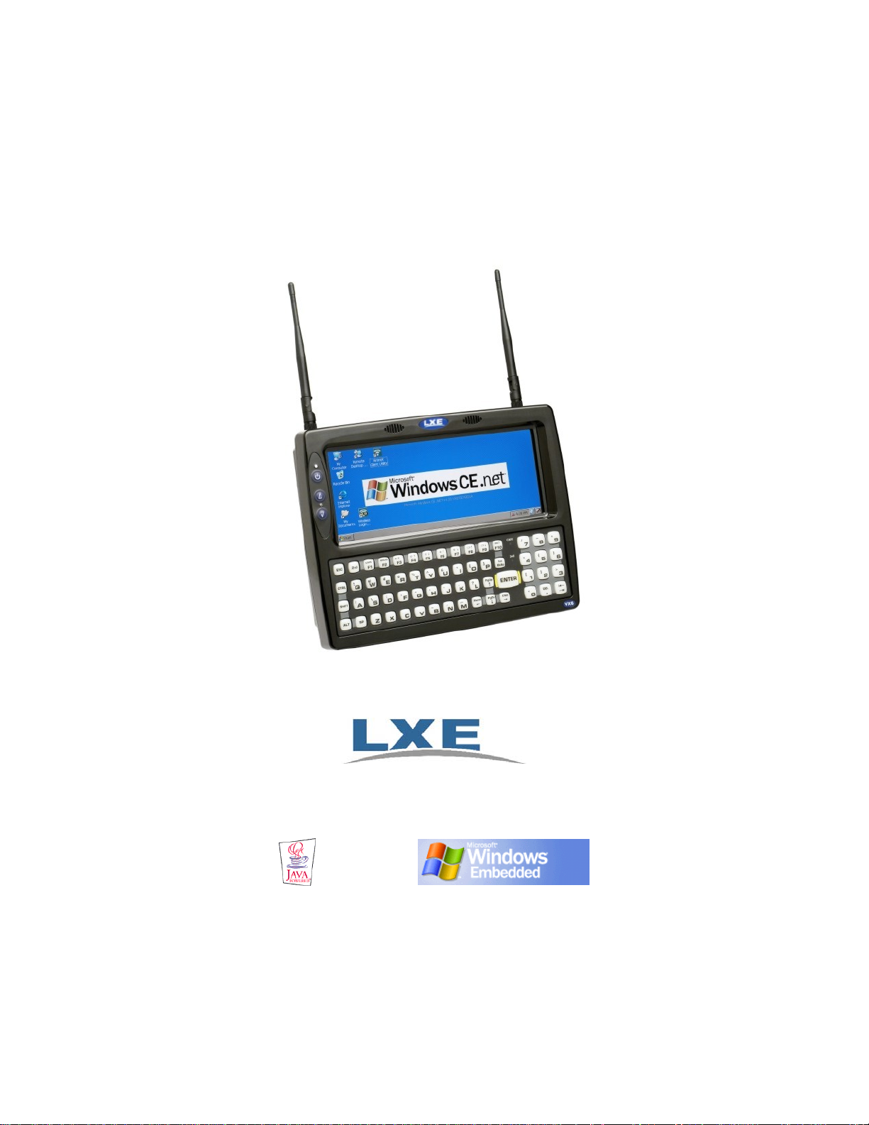
VX6 Reference Guide
Copyright © September 2008 by LXE Inc.
All Rights Reserved
E-EQ-VX6RG-J
Page 2

Notices
Notice:
LXE Inc. reserves the right to make improvements or changes in the products described in this manual at any time
without notice. While reasonable efforts have been made in the preparation of this document to assure its
accuracy, LXE assumes no liability resulting from any errors or omissions in this document, or from the use of the
information contained herein. Further, LXE Incorporated, reserves the right to revise this publication and to make
changes to it from time to time without any obligation to notify any person or organization of such revision or
changes.
Copyright Notice:
This manual is copyrighted. All rights are reserved. This document may not, in whole or in part, be copied,
photocopied, reproduced, translated or reduced to any electronic medium or machine-readable form without prior
consent, in writing, from LXE Inc.
Copyright © 2008 by LXE Inc. An EMS Technologies Company.
125 Technology Parkway, Norcross, GA 30092 U.S.A. (770) 447-4224
Trademarks:
LXE® is a registered trademark of LXE Inc. RFTerm® is a registered trademark of EMS Technologies, Norcross, GA.
Microsoft, Windows and the Windows logo are registered trademarks of Microsoft Corporation in the United
States and/or other countries.
Java® and Java-based trademarks and logos are trademarks or registered trademarks of Sun Microsystems, Inc. in
the U.S. or other countries, and are used under license.
Intel and Intel XScale are trademarks or registered trademarks of Intel Corporation or its subsidiaries in the United States and
other countries.
RAM® and RAM Mount™ are both trademarks of National Products Inc., 1205 S. Orr Street, Seattle, WA
98108.
The Cisco Square Bridge logo is a trademark of Cisco Systems, Inc.; Aironet, Cisco and Cisco Systems are
registered trademarks of Cisco Systems, Inc. and/or its affiliates in the United States and certain other countries.
Summit Data Communications, Inc. Summit Data Communications, the Summit logo, and “The Pinnacle of
Performance” are trademarks of Summit Data Communications, Inc. All rights reserved.
Symbol, the Symbol logo and Spectrum24 are registered trademarks of Symbol Technologies, Inc.
The Bluetooth® word mark and logos are owned by the Bluetooth SIG, Inc. and any use of such marks by LXE,
Inc. is under license.
Wavelink® and Wavelink Avalanche® are registered trademarks and the Wavelink logo, tagline and Avalanche
MC are trademarks of Wavelink Corporation, Kirkland, WA.
All other brand or product names are trademarks or registered trademarks of their respective companies or
organizations.
When this manual is in PDF format: “Acrobat® Reader® Copyright © 2008 Adobe Systems Incorporated. All
rights reserved. Adobe®, the Adobe logo, Acrobat®, and the Acrobat logo are registered trademarks of Adobe
Systems Incorporated.” applies.
Page 3

Revision Notice
VX6 Reference Guide
Upgrade From Revision H to Revision J
Section Explanation
Chapter 5 – Wireless Network
Configuration
Note: A complete revision history is included in Appendix C, “Reference Material”.
Added sections: “Auto Profile” and “Auth Server”
Revised sections: “Main Tab”, “Radio Mode” and “Hide Password”.
Page 4

Page 5

Table of Contents
CHAPTER 1 INTRODUCTION 1
Overview....................................................................................................................1
When to Use this Guide............................................................................................ 2
Document Conventions ............................................................................................................3
Quick Start.................................................................................................................4
Troubleshooting........................................................................................................................4
Entering the Multi AppLock Activation Key...........................................................................5
Hotkey (Activation hotkey)....................................................................................................5
Touch......................................................................................................................................5
Components.............................................................................................................. 6
Data Entry..................................................................................................................9
Keyboard Data Entry ................................................................................................................9
Tethered Scanners.....................................................................................................................9
Bluetooth Scanners...................................................................................................................9
RS-232 Data Entry....................................................................................................................9
Touchscreen Entry..................................................................................................................10
Right Click ...........................................................................................................................10
Input Panel (Virtual Keyboard)............................................................................................10
Touchscreen and Mouse.......................................................................................................11
Setup the Radio and Network................................................................................ 12
Setup Terminal Emulation Parameters ................................................................. 12
Configuring the VX6 with LXEConnect.................................................................13
Install LXEConnect ................................................................................................................
Using LXEConnect.................................................................................................................
ActiveSync – Initial Setup ......................................................................................
13
15
16
USB Connection .....................................................................................................................16
Serial Connection ...................................................................................................................
Connect.................................................................................................................................
16
16
Radio.......................................................................................................................................16
Bluetooth.................................................................................................................17
Initial Use ...............................................................................................................................
Settings Tab | Bluetooth Options .........................................................................................
Report when connection lost.......................................................................................................... 18
Report when reconnected............................................................................................................... 18
Report failure to reconnect............................................................................................................. 18
E-EQ-VX6RG-J VX6 Reference Guide
17
18
Page 6

ii Table of Contents
Computer is connectable................................................................................................................ 18
Computer is discoverable............................................................................................................... 18
Prompt if devices request to pair ................................................................................................... 18
Continuous search..........................................................................................................................19
Subsequent Use.......................................................................................................................19
Bluetooth Devices...................................................................................................................20
Bluetooth Barcode Reader Setup .........................................................................................21
Introduction.................................................................................................................................... 21
VX6 with Label ............................................................................................................................. 21
VX6 without Label ........................................................................................................................22
Bluetooth Beep and LED Indications ............................................................................................ 23
Saving Changes to the Registry............................................................................ 24
Getting Help.............................................................................................................
Manuals and Accessories......................................................................................
Manuals...................................................................................................................................25
Accessories .............................................................................................................................
C
HAPTER 2 PHYSICAL DESCRIPTION AND LAYOUT 29
Identifying Your VX6...............................................................................................29
Hardware Platforms................................................................................................................29
Software Revisions .................................................................................................................29
Hardware Configuration.........................................................................................30
System Hardware....................................................................................................................30
Central Processing Unit..........................................................................................................31
I/O Components......................................................................................................................31
System Memory......................................................................................................................31
Video Subsystem ....................................................................................................................31
Power Supply..........................................................................................................................32
Uninterruptible Power Supply..............................................................................................
Backup Battery.....................................................................................................................32
PCMCIA Slots........................................................................................................................32
CF Slot....................................................................................................................................
SD Slot....................................................................................................................................
Bluetooth LXEZ Pairing.........................................................................................................33
25
25
25
32
32
32
Power Modes...........................................................................................................34
Physical Controls....................................................................................................
35
On/Off Switch.........................................................................................................................35
External Connectors...............................................................................................36
Scanner Serial Connector (COM1).........................................................................................
37
Pinout ...................................................................................................................................37
Printer/PC Serial Connector (COM3).....................................................................................
Pinout ...................................................................................................................................
VX6 Reference Guide E-EQ-VX6RG-J
38
38
Page 7

Table of Contents iii
Technical Specifications – Connection Cable......................................................................39
RTS/CTS Handshaking and the Serial Port................................................................................... 39
Technical Specifications – Screen Blanking Cable .............................................................40
Ethernet/USB Connector ........................................................................................................41
Pinout ...................................................................................................................................
Ethernet/USB Dongle Cables .................................................................................................
41
42
D15 Female Connector.........................................................................................................43
Pinout............................................................................................................................................. 43
USB Host Connector............................................................................................................44
Pinout............................................................................................................................................. 44
USB Client Connector..........................................................................................................44
Pinout............................................................................................................................................. 44
RJ45 Connector....................................................................................................................45
Pinout............................................................................................................................................. 45
Audio Connector.....................................................................................................................46
Pinout ...................................................................................................................................46
Power Supply Connector ........................................................................................................47
Pinout ...................................................................................................................................47
UPS Battery Pack Connectors ................................................................................................48
Input .....................................................................................................................................48
Pinout............................................................................................................................................. 48
Output...................................................................................................................................48
Pinout............................................................................................................................................. 48
UPS Battery Extension Cable Connectors..............................................................................49
Input .....................................................................................................................................49
Pinout............................................................................................................................................. 49
Output...................................................................................................................................49
Pinout............................................................................................................................................. 49
Antenna Connections..............................................................................................................50
Spread Spectrum RF Antenna Connector Pin......................................................................50
Vehicle Remote Antenna Mount..........................................................................................50
Internal Antenna .....................................................................................................................
51
The QWERTY Keyboard ......................................................................................... 52
IBM 3270 Overlay..................................................................................................................52
IBM 5252 Overlay..................................................................................................................52
Key Maps................................................................................................................................
53
Custom Key Maps................................................................................................................53
NumLock and the VX6...........................................................................................................
Keyboard Backlight................................................................................................................
53
53
Keyboard LEDs ......................................................................................................................54
CAPS LED ...........................................................................................................................
54
Secondary Keys LED...........................................................................................................55
Control Keys ........................................................................................................................56
General Windows CE Keyboard Shortcuts ............................................................................
57
USB Keyboard/Mouse............................................................................................................57
Input Panel (Virtual Keyboard) ..............................................................................................
E-EQ-VX6RG-J VX6 Reference Guide
58
Page 8

iv Table of Contents
Enabling the Input Panel ......................................................................................................59
The Display..............................................................................................................60
Cleaning the Display ..............................................................................................................60
Touchscreen............................................................................................................................60
Touchscreen Heater..............................................................................................................
60
PCMCIA, CF and SD Slots......................................................................................
61
PCMCIA Slots........................................................................................................................61
PCMCIA Pinout ...................................................................................................................62
Install PCMCIA Cards .........................................................................................................63
Install the Type II PCMCIA Radio................................................................................................ 63
CF Card Slot ...........................................................................................................................
67
Replace a CF Card................................................................................................................67
SD Card Slot...........................................................................................................................68
Install an SD Card ................................................................................................................68
Power Supply..........................................................................................................69
External Power Supply ...........................................................................................................69
Specifications .......................................................................................................................70
Environmental Specifications ..............................................................................................70
Vehicle 12-80VDC Direct Connection...................................................................................71
VX6 Input Power Specifications..........................................................................................72
Power Adapter Cable ...........................................................................................................72
CMOS Battery ........................................................................................................................73
Fuse.........................................................................................................................................73
CHAPTER 3 SYSTEM CONFIGURATION 75
Introduction............................................................................................................. 75
Windows CE Operating System............................................................................. 75
Wireless Network Configuration............................................................................................
75
Warmboot ...............................................................................................................................75
Coldboot .................................................................................................................................
75
Installed Software................................................................................................... 76
Software Load.........................................................................................................................76
Software Applications..........................................................................................................76
Java (Optional) .....................................................................................................................
77
LXE RFTerm (Optional)......................................................................................................77
AppLock...............................................................................................................................
Wavelink Avalanche Enabler (Optional) .............................................................................
Desktop....................................................................................................................
77
77
79
Folders Copies at Startup........................................................................................................80
My Device Folders .................................................................................................................80
Start Menu Program Options.................................................................................81
Communication.......................................................................................................................
VX6 Reference Guide E-EQ-VX6RG-J
82
Page 9

Table of Contents v
ActiveSync ...........................................................................................................................82
Connect.................................................................................................................................83
Start FTP Server / Stop FTP Server .....................................................................................83
Command Prompt...................................................................................................................84
Internet Explorer.....................................................................................................................84
Media Player...........................................................................................................................84
Remote Desktop Connection ..................................................................................................85
Transcriber..............................................................................................................................85
Windows Explorer..................................................................................................................85
Taskbar ...................................................................................................................................86
Advanced Tab ......................................................................................................................86
Control Panel Options............................................................................................ 87
About ......................................................................................................................................88
Language and Fonts .............................................................................................................89
Identifying Software Versions .............................................................................................90
Radio MAC Address ............................................................................................................90
Accessibility ...........................................................................................................................91
Administrator Control.............................................................................................................92
Bluetooth.................................................................................................................................93
Discover ...............................................................................................................................94
Bluetooth Devices ................................................................................................................95
Bluetooth Device Properties .......................................................................................................... 96
Settings.................................................................................................................................97
Turn Off Bluetooth Button ............................................................................................................ 97
Options........................................................................................................................................... 97
About....................................................................................................................................98
Easy Pairing and Auto-Reconnect........................................................................................99
Certificates............................................................................................................................100
Date/Time .............................................................................................................................100
Dialing ..................................................................................................................................101
Display..................................................................................................................................102
Background ........................................................................................................................
102
Appearance.........................................................................................................................102
Backlight ............................................................................................................................102
Input Panel............................................................................................................................103
Internet Options ....................................................................................................................
Keyboard...............................................................................................................................
104
105
KeyPad..................................................................................................................................106
KeyMap..............................................................................................................................
106
LaunchApp.........................................................................................................................107
RunCmd..............................................................................................................................
How To: Remap a Single Key............................................................................................
How To: Remap a Key Sequence.......................................................................................
108
108
108
How To: Remap an Application Launch............................................................................108
How To: Remap a Command.............................................................................................
Mixer.....................................................................................................................................
109
110
E-EQ-VX6RG-J VX6 Reference Guide
Page 10

vi Table of Contents
Mouse ...................................................................................................................................111
MX3X-VXC Options............................................................................................................111
Communication ..................................................................................................................111
Enable TCP/IP Version 6............................................................................................................. 111
Allow Remote Desktop Autologon.............................................................................................. 111
Autolaunch TimeSync .................................................................................................................112
Misc....................................................................................................................................112
CapsLock ..................................................................................................................................... 112
Touch Screen Disable .................................................................................................................. 112
Touch Screen Heater Disable....................................................................................................... 112
Network and Dialup Connections.........................................................................................113
Owner ...................................................................................................................................114
Password...............................................................................................................................115
PC Connection......................................................................................................................116
PCMCIA...............................................................................................................................
Power ....................................................................................................................................
117
118
Regional Settings..................................................................................................................119
Remove Programs.................................................................................................................119
Scanner .................................................................................................................................119
Stylus ....................................................................................................................................120
Double Tap.........................................................................................................................120
Calibration..........................................................................................................................120
System...................................................................................................................................121
General ...............................................................................................................................121
Memory ..............................................................................................................................122
Device Name......................................................................................................................122
Copyrights ..........................................................................................................................122
Terminal Server Client Licenses ..........................................................................................123
Volume and Sounds..............................................................................................................123
Wi-Fi.....................................................................................................................................123
CF Flash Cards, CAB Files and Programs..........................................................124
Access Files on the Flash Card.............................................................................................
124
Backup VX6 Files using ActiveSync ................................................................... 125
Prerequisites..........................................................................................................................125
VX6 and ActiveSync Partnership ......................................................................................
Serial Port Transfer ............................................................................................................
125
125
USB Transfer......................................................................................................................126
Connect.................................................................................................................................
126
Explore..................................................................................................................................126
Disconnect ............................................................................................................................
Serial Connection ...............................................................................................................
127
127
USB Connection.................................................................................................................127
Radio Connection...............................................................................................................127
Important Information – Cold Boot and Loss of Host Re-connection...............................
Troubleshooting....................................................................................................................
127
128
Create a Communication Option ..........................................................................................129
VX6 Reference Guide E-EQ-VX6RG-J
Page 11

Table of Contents vii
Technical Specifications – Connection Cable......................................................................130
VX6 Utilities...........................................................................................................131
LAUNCH.EXE.....................................................................................................................131
REGEDIT.EXE ....................................................................................................................133
REGLOAD.EXE ..................................................................................................................
REGDUMP.EXE..................................................................................................................
133
133
WARMBOOT.EXE..............................................................................................................133
WAVPLAY.EXE..................................................................................................................133
VX6 Command-line Utilites.................................................................................................133
COLDBOOT.EXE .............................................................................................................133
PrtScrn.EXE .......................................................................................................................133
API Calls ................................................................................................................ 134
Reflash the VX6.....................................................................................................135
How To: Reflash using Keypress Method...........................................................................135
How To: Reflash using TAG file Method ...........................................................................136
Clearing Persistent Storage................................................................................. 137
Network Configuration ......................................................................................... 137
Wireless Radios ....................................................................................................................137
Ethernet Connector ...............................................................................................................137
Wavelink Avalanche Enabler Configuration....................................................... 138
Briefly . . ..............................................................................................................................138
Enabler Install Process..........................................................................................................138
Enabler Install Process..........................................................................................................138
Enabler Uninstall Process.....................................................................................................138
Stop the Enabler Service.......................................................................................................139
Update Monitoring Overview...............................................................................................139
Mobile Device Wireless and Network Settings....................................................................140
Enabler Configuration ..........................................................................................................141
File Menu Options..............................................................................................................
Avalanche Update Settings ................................................................................................
Menu Options .............................................................................................................................. 143
Connection................................................................................................................................... 144
Execution ..................................................................................................................................... 145
Server Contact.............................................................................................................................. 146
Startup/Shutdown......................................................................................................................... 147
Scan Config.................................................................................................................................. 148
Display......................................................................................................................................... 148
Shortcuts ......................................................................................................................................149
Adapters....................................................................................................................................... 150
Status............................................................................................................................................ 153
142
143
eXpress Scan ........................................................................................................ 154
E-EQ-VX6RG-J VX6 Reference Guide
Page 12

viii Table of Contents
CHAPTER 4 SCANNER 157
Introduction........................................................................................................... 157
Barcode Processing Overview ............................................................................
Barcode Manipulation ..........................................................................................
157
158
Main Tab...............................................................................................................................159
COM Port Tabs.....................................................................................................................160
Barcode Tab..........................................................................................................................161
Buttons ...............................................................................................................................161
Enable Code ID ..................................................................................................................162
Barcode – Symbology Settings ..........................................................................................163
Strip Leading/Trailing Control ....................................................................................................165
Barcode Data Match List ............................................................................................................. 166
Barcode Data Edit Buttons.......................................................................................................................166
Match List Rules ......................................................................................................................................167
Add Prefix/Suffix Control........................................................................................................................168
Barcode – Ctrl Char Mapping......................................................................................................169
Translate All.............................................................................................................................................169
Barcode – Custom Identifiers ......................................................................................................170
Control Code Replacement Examples .........................................................................................172
Barcode Processing Examples ..................................................................................................... 173
Length Based Barcode Stripping ........................................................................ 174
Screen Blanking....................................................................................................176
Operation ..............................................................................................................................177
CHAPTER 5 WIRELESS NETWORK CONFIGURATION 179
Introduction........................................................................................................... 179
Summit Radio........................................................................................................180
Summit Client Utility ...........................................................................................................181
Help ....................................................................................................................................
181
Summit Tray Icon...............................................................................................................182
Wireless Zero Config Utility and the Summit Radio.........................................................182
Main Tab ............................................................................................................................
Admin Login................................................................................................................................184
Auto Profile.................................................................................................................................. 185
Profile Tab..........................................................................................................................
Using the Scan Feature ................................................................................................................187
Parameters.................................................................................................................................... 188
Status Tab...........................................................................................................................
Diags Tab ...........................................................................................................................
Global Tab..........................................................................................................................
Parameters.................................................................................................................................... 193
183
186
191
192
193
Sign-On vs. Stored Credentials ............................................................................................199
Windows Certificate Store vs. Certs Path ............................................................................201
VX6 Reference Guide E-EQ-VX6RG-J
Page 13

Table of Contents ix
User Certificates.................................................................................................................201
Root CA Certificates ..........................................................................................................201
Summit Wireless Security ....................................................................................................203
No Security.........................................................................................................................204
WEP....................................................................................................................................205
LEAP without WPA Authentication..................................................................................206
PEAP/MSCHAP.................................................................................................................208
PEAP/GTC.........................................................................................................................210
WPA/LEAP........................................................................................................................212
EAP-FAST .........................................................................................................................214
EAP-TLS............................................................................................................................216
WPA PSK...........................................................................................................................218
Cisco Radio...........................................................................................................219
Cisco – Aironet Client Utility (ACU) ................................................................................219
Profiles Tab..................................................................................................................................220
No Security...............................................................................................................................................220
WEP .........................................................................................................................................................221
LEAP........................................................................................................................................................221
Firmware Tab............................................................................................................................... 222
Status Tab .................................................................................................................................... 222
Statistics Tab................................................................................................................................222
Survey Tab................................................................................................................................... 222
Configuring for WPA ...........................................................................................................223
System Requirements.........................................................................................................223
Installing Radio drivers ......................................................................................................223
Checking for the Cisco PEAP Supplicant.................................................................................... 224
Wireless Network Configuration .......................................................................................226
PEAP/MS-CHAP Authentication Configuration...............................................................229
Configuring the PEAP/MS-CHAP Supplicant ............................................................................229
Server Authentication ..................................................................................................................231
PEAP/ GTC Authentication Configuration........................................................................
Configuring the PEAP / GTC Supplicant .................................................................................... 232
Server Authentication ..................................................................................................................234
232
WPA/LEAP........................................................................................................................237
Cisco ACU................................................................................................................................... 237
EAP-TLS Authentication Configuration............................................................................
User Certificate ............................................................................................................................ 240
Setting EAP/TLS Parameters....................................................................................................... 241
Validating the Server Certificate.................................................................................................. 243
WPA PSK Configuration ...................................................................................................
240
244
Symbol Radio........................................................................................................ 245
IP Information Tab ...............................................................................................................245
IPv6 Information Tab ...........................................................................................................245
Wireless Information Tab.....................................................................................................246
View Log............................................................................................................................
Add a new connection........................................................................................................
246
247
Select a User Certificate.....................................................................................................248
E-EQ-VX6RG-J VX6 Reference Guide
Page 14

x Table of Contents
Certificates ............................................................................................................ 249
Root Certificates...................................................................................................................249
Generating a Root CA Certificate ......................................................................................249
Installing a Root CA Certificate.........................................................................................251
User Certificates ...................................................................................................................
Generating a User Certificate.............................................................................................
253
253
Installing a User Certificate ...............................................................................................258
CHAPTER 6 APPLOCK 263
Introduction........................................................................................................... 263
Determining Your AppLock Version ...................................................................................264
Multi-Application AppLock...............................................................................................264
Single Application AppLock..............................................................................................
265
Setup a New Device..............................................................................................
266
Administration Mode ............................................................................................ 267
End User Mode......................................................................................................267
Passwords............................................................................................................. 268
End-User Switching Technique ........................................................................... 269
Using a Stylus Tap................................................................................................................269
Using the Switch Key Sequence...........................................................................................269
Application Configuration.................................................................................... 270
Application Panel .................................................................................................................270
Launch Button....................................................................................................................273
Auto At Boot................................................................................................................................ 273
Auto Re-Launch........................................................................................................................... 274
Manual (Launch).......................................................................................................................... 274
Allow Close .................................................................................................................................274
Match ........................................................................................................................................... 275
End User Internet Explorer (EUIE)....................................................................................275
Security Panel .......................................................................................................................276
Password.............................................................................................................................277
Options Panel........................................................................................................................
Launch timeout...................................................................................................................
277
277
Replace timeout..................................................................................................................277
Restart timeout ...................................................................................................................
277
Status Panel...........................................................................................................................278
View ...................................................................................................................................
Log .....................................................................................................................................
Save As...............................................................................................................................
278
279
279
Troubleshooting AppLock ................................................................................... 280
VX6 Reference Guide E-EQ-VX6RG-J
Page 15

Table of Contents xi
APPENDIX A KEY MAPS 281
The VX6 Keypad....................................................................................................281
Key Map 101-Key Equivalencies..........................................................................
IBM 3270 Terminal Emulator Keypad..................................................................
281
286
IBM 5250 Terminal Emulator Keypad.................................................................. 286
APPENDIX B TECHNICAL SPECIFICATIONS 287
Physical Specifications........................................................................................ 287
Environmental Specifications..............................................................................288
Display Specifications ..........................................................................................................289
UPS Battery Pack Specifications..........................................................................................289
Network Device Specifications............................................................................ 290
Summit 802.11b/g CF 2.4GHz .............................................................................................290
Summit 802.11a/b/g CF 2.4/5.0GHz ....................................................................................290
Bluetooth...............................................................................................................................290
PCMCIA Cisco 2.4GHz Type II ..........................................................................................291
PCMCIA Symbol 11Mb 2.4GHz Type II.............................................................................291
APPENDIX C VX6 CE .NET 4.2 293
Introduction........................................................................................................... 293
Windows CE . NET 4.2 Operating System........................................................... 293
Wireless Network Configuration..........................................................................................293
Warmboot .............................................................................................................................293
Coldboot ...............................................................................................................................
Installed Software.................................................................................................
Software Load.......................................................................................................................
293
294
294
Software Applications........................................................................................................294
Java (Optional) ...................................................................................................................295
LXE RFTerm (Optional)....................................................................................................
AppLock.............................................................................................................................
295
295
Wavelink Avalanche Enabler (Optional) ...........................................................................295
Desktop..................................................................................................................297
Folders Copies at Startup......................................................................................................298
My Computer Folders...........................................................................................................
Start Menu Program Options...............................................................................
Communication.....................................................................................................................
298
299
300
ActiveSync .........................................................................................................................300
Connect...............................................................................................................................
301
E-EQ-VX6RG-J VX6 Reference Guide
Page 16

xii Table of Contents
Start FTP Server / Stop FTP Server ...................................................................................301
Command Prompt.................................................................................................................302
Internet Explorer...................................................................................................................302
Media Player.........................................................................................................................302
Remote Desktop Connection ................................................................................................303
Transcriber............................................................................................................................303
Windows Explorer................................................................................................................303
Taskbar .................................................................................................................................304
Advanced Tab ....................................................................................................................304
Control Panel Options.......................................................................................... 305
About ....................................................................................................................................306
Language and Fonts ...........................................................................................................307
Identifying Software Versions ...........................................................................................308
Radio MAC Address ..........................................................................................................308
Accessibility .........................................................................................................................309
Administrator Control...........................................................................................................310
Bluetooth...............................................................................................................................310
Certificates............................................................................................................................310
Date/Time .............................................................................................................................311
Dialing ..................................................................................................................................312
Display..................................................................................................................................313
Background ........................................................................................................................313
Appearance.........................................................................................................................313
Backlight ............................................................................................................................313
Input Panel............................................................................................................................314
Internet Options ....................................................................................................................315
Keyboard...............................................................................................................................315
Mixer.....................................................................................................................................316
Mouse ...................................................................................................................................317
Network and Dialup Connections.........................................................................................
Owner ...................................................................................................................................
Password...............................................................................................................................
317
318
319
PC Connection......................................................................................................................320
PCMCIA...............................................................................................................................321
Power ....................................................................................................................................
322
Regional Settings..................................................................................................................323
Remove Programs.................................................................................................................
323
Scanner .................................................................................................................................323
Storage Manager...................................................................................................................
Stylus ....................................................................................................................................
323
324
Double Tap.........................................................................................................................324
Calibration..........................................................................................................................
324
System...................................................................................................................................325
General ...............................................................................................................................
Memory ..............................................................................................................................
325
326
VX6 Reference Guide E-EQ-VX6RG-J
Page 17

Table of Contents xiii
Device Name......................................................................................................................326
Copyrights ..........................................................................................................................326
Volume and Sounds..............................................................................................................327
APPENDIX D REFERENCE MATERIAL 329
Introduction........................................................................................................... 329
AppLock Error Messages.....................................................................................330
AppLock Registry Settings.................................................................................. 339
Valid VK Codes for CE..........................................................................................
ASCII Control Codes.............................................................................................
340
341
Hat Encoding.........................................................................................................343
Decimal - Hexadecimal Chart...............................................................................345
Revision History.................................................................................................... 347
INDEX 353
E-EQ-VX6RG-J VX6 Reference Guide
Page 18

xiv Table of Contents
Illustrations
Figure 1-1 VX6 Components, Top View.............................................................................................................6
Figure 1-2 VX6 Components, Front View...........................................................................................................6
Figure 1-3 VX6 Components, Bottom View .......................................................................................................7
Figure 1-4 VX6 Components, Back View...........................................................................................................7
Figure 1-5 VX6 Control Panel.............................................................................................................................8
Figure 1-6 VX6 Access Panel.............................................................................................................................. 8
Figure 1-7 ActiveSync Explore .........................................................................................................................13
Figure 1-8 LXEConnect Installation Files.........................................................................................................14
Figure 1-9 LXEConnect Setup...........................................................................................................................14
Figure 1-10 LXEConnect Notice.......................................................................................................................15
Figure 1-11 LXEConnect Desktop ....................................................................................................................15
Figure 1-12 Bluetooth Devices Display – Before Discovering Devices............................................................17
Figure 1-13 Sample Bluetooth Address Barcode Label.....................................................................................21
Figure 1-14 About tab and Bluetooth Address ..................................................................................................22
Figure 2-1 VX6 Hardware Configuration..........................................................................................................30
Figure 2-2 The Power (On/Off) Switch.............................................................................................................35
Figure 2-3 Scanner Serial Connector (COM1) ..................................................................................................37
Figure 2-4 Printer/PC Serial Connector (COM3) ..............................................................................................38
Figure 2-5 Pinout – Serial Cable........................................................................................................................39
Figure 2-6 Pinout – Screen Blanking Cable.......................................................................................................40
Figure 2-7 Sample Cable for Screen Blanking ..................................................................................................40
Figure 2-8 VX6 USB Connector and External USB Adapter Cable Connector................................................41
Figure 2-9 VX6 Ethernet/USB Dongle Cables..................................................................................................42
Figure 2-10 D15 Female Connector...................................................................................................................43
Figure 2-11 Dongle Cable USB Host Port.........................................................................................................44
Figure 2-12 Dongle Cable USB Client Port.......................................................................................................44
Figure 2-13 Dongle Cable Ethernet Port............................................................................................................45
Figure 2-14 VX6 Audio Jack for External Speaker or Headphones..................................................................46
Figure 2-15 The Power Connector.....................................................................................................................47
Figure 2-16 The UPS Battery Pack Input Connector.........................................................................................48
Figure 2-17 The UPS Battery Pack Output Connector......................................................................................48
Figure 2-18 The UPS Battery Extension Cable Input Connector ......................................................................49
Figure 2-19 The UPS Battery Extension Cable Output Connector....................................................................49
Figure 2-20 External Antenna............................................................................................................................50
Figure 2-21 RF Antenna SS Connector .............................................................................................................50
Figure 2-22 Internal Antenna Cables.................................................................................................................51
Figure 2-23 QWERTY Keyboard Standard.......................................................................................................52
Figure 2-24 QWERTY Keyboard with IBM 3270 Overlay ..............................................................................52
Figure 2-25 QWERTY Keyboard with IBM 5250 Overlay ..............................................................................52
Figure 2-26 Keyboard LEDs..............................................................................................................................54
Figure 2-27 The CapsLock Key.........................................................................................................................54
Figure 2-28 The Secondary Key........................................................................................................................55
Figure 2-29 The VMT Keyboard Display Controls...........................................................................................56
Figure 2-30 Small and Large Virtual Keyboards...............................................................................................58
Figure 2-31 Input Panel Properties ....................................................................................................................59
Figure 2-32 The PCMCIA and ATA Slots ........................................................................................................61
Figure 2-33 Inserting the Type II PCMCIA Radio............................................................................................63
Figure 2-34 Summit 802.11 a/b/g Antenna Cable Connections.........................................................................64
Figure 2-35 Summit 802.11b/g Antenna Cable Connections ............................................................................65
Figure 2-36 Cisco Antenna Cable Connections.................................................................................................65
Figure 2-37 Symbol 11Mb Antenna Cable Connections...................................................................................66
VX6 Reference Guide E-EQ-VX6RG-J
Page 19

Table of Contents xv
Figure 2-38 Inserting the CF ATA Card............................................................................................................67
Figure 2-39 Inserting the SD ATA Card............................................................................................................68
Figure 2-40 Optional Power Supply Cable........................................................................................................69
Figure 2-41 Direct Vehicle Power Connection Cable (12 Ft.)...........................................................................71
Figure 2-42 Connecting the Power Cable to the Vehicle...................................................................................71
Figure 2-43 Vehicle Connection Wiring Color Codes.......................................................................................71
Figure 2-44 Power Adapter Cable, VX1/2/4 to VX6.........................................................................................72
Figure 2-45 Fuse Replacement ..........................................................................................................................73
Figure 3-1 Pocket CMD Prompt Screen ............................................................................................................84
Figure 3-2 Taskbar Properties............................................................................................................................86
Figure 3-3 About Properties, Software ..............................................................................................................89
Figure 3-4 About Properties, Versions ..............................................................................................................90
Figure 3-5 About Properties, Network IP..........................................................................................................90
Figure 3-6 Accessibility Properties, Keyboard..................................................................................................91
Figure 3-7 Accessibility Properties, Sound........................................................................................................91
Figure 3-8 Control Panel - Bluetooth.................................................................................................................94
Figure 3-9 Discover Bluetooth Devices.............................................................................................................94
Figure 3-10 Bluetooth Devices Panel ................................................................................................................95
Figure 3-11 Bluetooth Device Disconnect / Delete ...........................................................................................96
Figure 3-12 Bluetooth Device Properties Menu ................................................................................................96
Figure 3-13 Bluetooth Device Settings Panel....................................................................................................97
Figure 3-14 Bluetooth About Panel ...................................................................................................................98
Figure 3-15 Date/Time Properties....................................................................................................................100
Figure 3-16 Dialing..........................................................................................................................................101
Figure 3-17 Display Properties / Backlight Tab ..............................................................................................102
Figure 3-18 Input Panel Properties ..................................................................................................................103
Figure 3-19 KeyPad Properties / KeyMap Tab................................................................................................106
Figure 3-20 KeyMap Properties / LaunchApp Tab .........................................................................................107
Figure 3-21 KeyMap Properties / RunCmd Tab..............................................................................................108
Figure 3-22 Mixer............................................................................................................................................110
Figure 3-23 MX3X-VXC Options Properties / Communication Tab..............................................................111
Figure 3-24 MX3X-VXC Options Properties / Misc Tab................................................................................112
Figure 3-25 Network Connection Properties ...................................................................................................113
Figure 3-26 Owner Properties..........................................................................................................................114
Figure 3-27 Password Properties .....................................................................................................................115
Figure 3-28 Communication / PC Connection Tab..........................................................................................116
Figure 3-29 PCMCIA Control Tab, Slot 0 and Slot 1 .....................................................................................117
Figure 3-30 Compact Flash ATA Control Tab, Slot 2.....................................................................................117
Figure 3-31 Power Properties ..........................................................................................................................118
Figure 3-32 Stylus Properties / Recalibration Start..........................................................................................120
Figure 3-33 Stylus Properties / Recalibration..................................................................................................120
Figure 3-34 System / General tab ....................................................................................................................121
Figure 3-35 System / Memory .........................................................................................................................122
Figure 3-36 System / Device Name .................................................................................................................122
Figure 3-37 Volume and Sounds .....................................................................................................................123
Figure 3-38 Pinout – Serial Cable for Synchronization...................................................................................130
Figure 3-39 Avalanche Enabler Opening Screen.............................................................................................141
Figure 3-40 Connection Options......................................................................................................................144
Figure 3-41 Execution Options (Dimmed) ......................................................................................................145
Figure 3-42 Server Contact Options ................................................................................................................146
Figure 3-43 Startup / Shutdown Options .........................................................................................................147
Figure 3-44 Scan Config Option......................................................................................................................148
Figure 3-45 Window Display Options.............................................................................................................148
Figure 3-46 Application Shortcuts...................................................................................................................149
Figure 3-47 Adapter Options – Network .........................................................................................................150
E-EQ-VX6RG-J VX6 Reference Guide
Page 20

xvi Table of Contents
Figure 3-48 Avalanche Network Profile Displayed..........................................................................................151
Figure 3-49 Manual Settings Properties Panels ...............................................................................................152
Figure 3-50 Status Display...............................................................................................................................153
Figure 3-51 eXpress Scan Desktop Icon..........................................................................................................154
Figure 3-52 eXpress Scan Password Input ......................................................................................................154
Figure 3-53 Scan Barcode 1.............................................................................................................................155
Figure 3-54 Scan Remaining Barcodes............................................................................................................155
Figure 2-55 Configuring Settings ....................................................................................................................156
Figure 4-1 Scanner Control / Main Tab...........................................................................................................159
Figure 4-2 Scanner Control / COM Port Tab...................................................................................................160
Figure 4-3 Scanner Control / Barcode tab .......................................................................................................161
Figure 4-4 Barcode Tab – Symbology Settings...............................................................................................163
Figure 4-5 Strip Leading/Trailing Controls .....................................................................................................165
Figure 4-6 Barcode Data Match List................................................................................................................166
Figure 4-7 Add Prefix/Suffix Controls ............................................................................................................168
Figure 4-8 Barcode Tab – Ctrl Char Mapping.................................................................................................169
Figure 4-9 Barcode Tab – Custom Identifiers .................................................................................................171
Figure 4-10 AIM Custom IDs..........................................................................................................................174
Figure 4-11 AIM Custom Setup for C1 ...........................................................................................................175
Figure 4-12 Barcode Match Data for C1 .........................................................................................................175
Figure 4-13 Enable Screen Blanking ...............................................................................................................176
Figure 5-1 Summit Client Utility.....................................................................................................................181
Figure 5-2 SCU – Main Tab ............................................................................................................................183
Figure 5-3 Admin Password Entry ..................................................................................................................184
Figure 5-4 Select Profiles for Auto Profile ......................................................................................................185
Figure 5-5 SCU – Profile Tab..........................................................................................................................186
Figure 5-6 Scan................................................................................................................................................187
Figure 5-7 SCU – Status Tab...........................................................................................................................191
Figure 5-8 SCU – Diags Tab ...........................................................................................................................192
Figure 5-9 SCU – Global Tab..........................................................................................................................193
Figure 5-10 Sign-On Screen ............................................................................................................................200
Figure 5-11 Choose Certificate........................................................................................................................202
Figure 5-12 Default Profile..............................................................................................................................203
Figure 5-13 No Security...................................................................................................................................204
Figure 5-14 WEP Encryption...........................................................................................................................205
Figure 5-15 WEP Keys....................................................................................................................................205
Figure 5-16 LEAP Configuration ....................................................................................................................206
Figure 5-17 LEAP Credentials.........................................................................................................................207
Figure 5-18 PEAP/MSCHAP ..........................................................................................................................208
Figure 5-19 PEAP/MSCHAP Credentials .......................................................................................................208
Figure 5-20 PEAP/MSCHAP Certificate Filename.........................................................................................209
Figure 5-21 PEAP/GTC...................................................................................................................................210
Figure 5-22 PEAP/GTC Credentials................................................................................................................210
Figure 5-23 PEAP/GTC Certificate Filename .................................................................................................211
Figure 5-24 WPA/LEAP..................................................................................................................................212
Figure 5-25 WPA/LEAP Credentials...............................................................................................................213
Figure 5-26 EAP-FAST Configuration............................................................................................................214
Figure 5-27 EAP-FAST Credentials................................................................................................................215
Figure 5-28 EAP-TLS......................................................................................................................................216
Figure 5-29 EAP-TLS Credentials...................................................................................................................216
Figure 5-30 EAP-TLS Credentials...................................................................................................................217
Figure 5-31 WPA/PSK Encryption..................................................................................................................218
Figure 5-32 PSK Entry ....................................................................................................................................218
Figure 5-33 Cisco Aironet Client Utility .........................................................................................................219
Figure 5-34 Cisco Profile Properties Screen.................................................................................................... 220
VX6 Reference Guide E-EQ-VX6RG-J
Page 21

Table of Contents xvii
Figure 5-35 Cisco Profile WEP Keys ..............................................................................................................221
Figure 5-36 No Cisco PEAP.............................................................................................................................224
Figure 5-37 Cisco PEAP installed. ...................................................................................................................224
Figure 5-38 Cisco ACU Profile Selection........................................................................................................226
Figure 5-39 Cisco ACU Reboot Message........................................................................................................226
Figure 5-40 Microsoft Wireless Connection Icon............................................................................................226
Figure 5-41 Wireless Information Screen........................................................................................................227
Figure 5-42 Advanced Wireless Settings.........................................................................................................227
Figure 5-43 Wireless Network Properties........................................................................................................228
Figure 5-44 PEAP/MSCHAP Wireless Network Properties ...........................................................................229
Figure 5-45 Authentication Settings ................................................................................................................229
Figure 5-46 Wireless Network Login ..............................................................................................................230
Figure 5-47 IP Information Tab.......................................................................................................................230
Figure 5-48 Authentication Settings, Validate Server .....................................................................................231
Figure 5-49 Advanced Wireless Settings, Authenticated SSID.......................................................................231
Figure 5-50 PEAP/GTC Wireless Network Properties....................................................................................232
Figure 5-51 PEAP Properties...........................................................................................................................232
Figure 5-52 Login Screen ................................................................................................................................233
Figure 5-53 IP Information Tab.......................................................................................................................233
Figure 5-54 PEAP Properties, Validate Server Certificate ..............................................................................234
Figure 5-55 Server Connection Warning.........................................................................................................234
Figure 5-56 PEAP Properties, Trusted Root Certificate ..................................................................................235
Figure 5-57 Accept Server Connection Warning.............................................................................................235
Figure 5-58 PEAP Properties, Connect Only If Server Name Ends In............................................................236
Figure 5-59 Wireless Information, Authenticated ...........................................................................................236
Figure 5-60 ACU Profile Tab ..........................................................................................................................237
Figure 5-61 Renaming Profile ..........................................................................................................................237
Figure 5-62 Profile Properties Screen..............................................................................................................238
Figure 5-63 Select Profile ................................................................................................................................238
Figure 5-64 Login Screen ................................................................................................................................239
Figure 5-65 ACU Status Tab ...........................................................................................................................239
Figure 5-66 Certificate Stores..........................................................................................................................240
Figure 5-67 View Certificate Details...............................................................................................................240
Figure 5-68 EAP/TLS Configuration...............................................................................................................241
Figure 5-69 Authentication Settings ................................................................................................................241
Figure 5-70 Select Certificate ..........................................................................................................................242
Figure 5-71 Authentication Settings, Certificate Details .................................................................................242
Figure 5-72 Validate Server.............................................................................................................................243
Figure 5-73 SSID Authenticated......................................................................................................................243
Figure 5-74 WPA PSK Configuration .............................................................................................................244
Figure 5-75 Symbol NETWLAN Screen.........................................................................................................245
Figure 5-76 Symbol Wireless Information Tab ...............................................................................................246
Figure 5-77 Symbol Wireless Network Properties ..........................................................................................247
Figure 5-78 Symbol Advanced Wireless Settings ...........................................................................................248
Figure 5-79 Logon to Certificate Authority.....................................................................................................249
Figure 5-80 Certificate Services Welcome Screen ..........................................................................................249
Figure 5-81 Download CA Certificate Screen.................................................................................................250
Figure 5-82 Download CA Certificate Screen.................................................................................................250
Figure 5-83 Certificates ...................................................................................................................................251
Figure 5-84 Import Certificate.........................................................................................................................251
Figure 5-85 Browsing to Certificate Location .................................................................................................252
Figure 5-86 Certificate Import Confirmation...................................................................................................252
Figure 5-87 Logon to Certificate Authority.....................................................................................................253
Figure 5-88 Certificate Services Welcome Screen ..........................................................................................253
Figure 5-89 Request a Certificate Screen ........................................................................................................254
E-EQ-VX6RG-J VX6 Reference Guide
Page 22

xviii Table of Contents
Figure 5-90 Advanced Certificate Request Screen ..........................................................................................254
Figure 5-91 Advanced Certificate Details .......................................................................................................255
Figure 5-92 Script Warnings............................................................................................................................256
Figure 5-93 Script Warnings............................................................................................................................256
Figure 5-94 Certificate Issued..........................................................................................................................257
Figure 5-95 Download Security Warning........................................................................................................257
Figure 5-96 Certificates ...................................................................................................................................258
Figure 5-97 Import Certificate.........................................................................................................................258
Figure 5-98 Browsing to Certificate Location .................................................................................................259
Figure 5-99 Certificate Listing.........................................................................................................................259
Figure 5-100 Private Key Not Present.............................................................................................................260
Figure 5-101 Browsing to Private Key Location.............................................................................................260
Figure 5-102 Private Key Present....................................................................................................................261
Figure 6-1 Multi-Application AppLock...........................................................................................................264
Figure 6-2 Single-Application AppLock .........................................................................................................265
Figure 6-3 Switchpad Menu.............................................................................................................................269
Figure 6-4 Application Panel...........................................................................................................................270
Figure 6-5 Application Launch Options ..........................................................................................................273
Figure 6-6 Security Panel.................................................................................................................................276
Figure 6-7 Options Panel .................................................................................................................................277
Figure 6-8 Status Panel ....................................................................................................................................278
Figure A-1 VX6 QWERTY Keyboard ............................................................................................................281
Figure A-2 IBM 3270 Specific Keypad...........................................................................................................286
Figure A-3 IBM 5250 Specific Keypad...........................................................................................................286
Figure C-1 Pocket CMD Prompt Screen..........................................................................................................302
Figure C-2 Taskbar Properties.........................................................................................................................304
Figure C-3 About Properties, Software ...........................................................................................................307
Figure C-4 About Properties, Versions............................................................................................................308
Figure C-5 About Properties, Network IP .......................................................................................................308
Figure C-6 Accessibility Properties, Keyboard ...............................................................................................309
Figure C-7 Accessibility Properties, Sound.....................................................................................................309
Figure C-8 Date/Time Properties.....................................................................................................................311
Figure C-9 Dialing ...........................................................................................................................................312
Figure C-10 Display Properties / Backlight Tab..............................................................................................313
Figure C-11 Input Panel Properties..................................................................................................................314
Figure C-12 Mixer ...........................................................................................................................................316
Figure C-13 Network Connection Properties...................................................................................................317
Figure C-14 Owner Properties.........................................................................................................................318
Figure C-15 Password Properties.....................................................................................................................319
Figure C-16 Communication / PC Connection Tab.........................................................................................320
Figure C-17 PCMCIA Control Tab, Slot 0 and Slot 1.....................................................................................321
Figure C-18 Compact Flash ATA Control Tab, Slot 2....................................................................................321
Figure C-19 Power Properties..........................................................................................................................322
Figure C-20 Stylus Properties / Recalibration Start.........................................................................................324
Figure C-21 Stylus Properties / Recalibration .................................................................................................324
Figure C-22 System / General tab....................................................................................................................325
Figure C-23 System / Memory.........................................................................................................................326
Figure C-24 System / Device Name.................................................................................................................326
Figure C-25 Volume and Sounds.....................................................................................................................327
Figure D-1 Decimal - Hexadecimal Chart (0 to 159 Decimal)........................................................................345
Figure D-2 Decimal - Hexadecimal Chart (160 to 255 Decimal)....................................................................346
VX6 Reference Guide E-EQ-VX6RG-J
Page 23
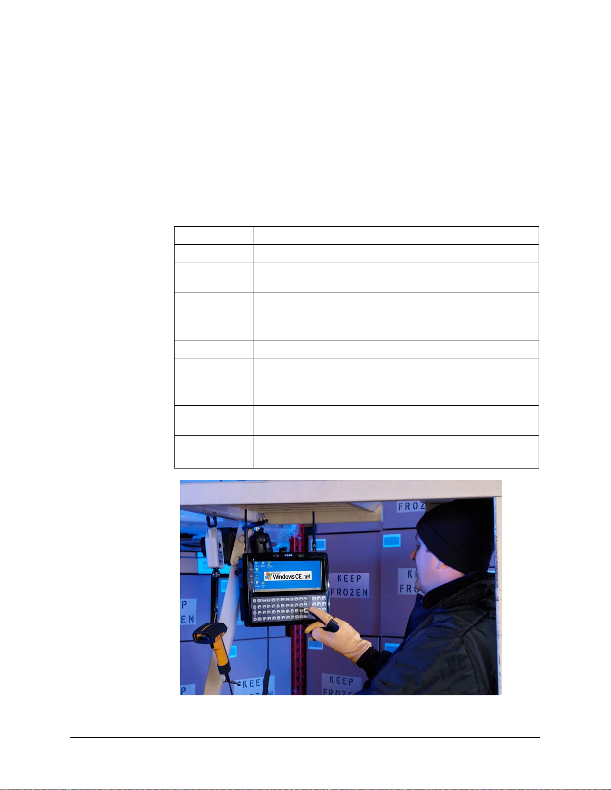
Overview
Chapter 1 Introduction
The VX6 Vehicle Mount Computer (VMC) is a rugged, vehicle mounted, PC (Personal
Computer) running a Microsoft
®
Windows® CE operating system and capable of wireless data
communications from a fork-lift truck or any properly configured vehicle. The VX6 provides
power and functionality in a vehicle mounted unit, with a wide range of options:
®
CPU 400MHz Intel
PXA255
Memory 128MB DRAM
Display
Indoor or Outdoor half screen display, integrated Touchscreen,
adjustable brightness
Wireless LAN radio (single or dual antenna)
Network
connectivity
Ethernet port
Optional Bluetooth module
Audio Speakers in front bezel, audio jack for headset with microphone
Compact Flash
Storage media
PCMCIA
Secure Digital (SD)
Operating
system
Other options
Microsoft Windows CE .NET 4.2 or CE 5.0
Extended temperature version
TM
RAM Mount
vehicle mounting
E-EQ-VX6RG-J VX6 Reference Guide
Page 24

2 When to Use this Guide
When to Use this Guide
The “VX6 User’s Guide” is directed toward the VX6 user. It is delivered on the LXE
Documentation CD. It contains safety warnings, descriptions of the controls and
connectors, instruction on installing antennas, and day to day operation.
As the reference for LXE’s VX6 equipped with a Microsoft Windows CE operating system, this
guide provides detailed information on its features and functionality. Use this guide as you would
any other source book -- reading portions to learn about the VX6, and then referring to it when
you need more information about a particular subject.
This chapter, “Introduction”, briefly describes this reference guide structure, contains setup and
installation instruction, briefly describes data entry processes, and explains how to get help.
Chapter 2 “Physical Description and Layout” describes the function and layout of the controls
and connectors on the VX6. Describes AC power and DC power connections.
Chapter 3 “System Configuration” takes you through the system setup and file structure,
covering all components except the wireless network, AppLock and Scanner.
Chapter 4 “Scanner” contains information on the scanner keyboard wedge, active scanner port,
and COM port settings such as baud rate, parity, stop bits and data bits.
Chapter 5, “Wireless Network Configuration” details radio setup. Configuration for WEP and
WPA is included.
Chapter 6, “AppLock” contains explanation and instruction when working with VX6’s running
AppLock.
Appendix A “Key Maps” describes the keypress sequences for the VX6 keyboard.
Appendix B “Technical Specifications” lists technical specifications including physical,
environmental, display and the radios.
Appendix C “VX6 CE .NET 4.2” takes you through the Windows CE .NET 4.2 system setup
and files structure.
Appendix D, “Reference Material” includes parameter programming charts and other reference
information.
VX6 Reference Guide E-EQ-VX6RG-J
Page 25
When to Use this Guide 3
Document Conventions
This reference guide uses the following document conventions:
ALL CAPS
Menu | Choice
“Quotes”
< >
P
S
ATTENTION
!
All caps are used to represent disk directories, file names, and application
names.
Rather than use the phrase “choose the Save command from the File menu”,
this guide uses the convention “choose File | Save”.
Indicates the title of a book, chapter or a section within a chapter (for example,
“Document Conventions”).
Indicates a key on the keyboard (for example, <Enter> ).
Indicates a reference to other documentation.
Differences in operation or commands due to platform type.
Differences in operation or commands due to software revision.
Keyword that indicates vital or pivotal information to follow.
Attention symbol that indicates vital or pivotal information to follow. Also,
when marked on product, means to refer to the manual or user’s guide.
Note: Keyword that indicates immediately relevant information.
Caution
!
WARNING
!
DANGER
!
International fuse replacement symbol. When marked on the product, the label
includes fuse ratings in volts (v) and amperes (a) for the product.
Keyword that indicates a potentially hazardous situation, which, if not avoided,
may result in minor or moderate injury.
Keyword that indicates a potentially hazardous situation, which, if not avoided,
could result in death or serious injury.
Keyword that indicates an imminent hazardous situation, which, if not avoided,
will result in death or serious injury.
E-EQ-VX6RG-J VX6 Reference Guide
Page 26

4 Quick Start
Quick Start
This section’s instructions are based on the assumption that your new system is pre-configured
and requires only accessory installation (e.g. antenna, external keyboard and/or barcode scanner)
and a power source.
In general, the sequence of events is:
1. Install Vehicle Mounting Bracket on vehicle and secure VX6 in Mounting Bracket
Assembly (see “VX6 User’s Guide”).
2. Connect power cable to the VX6. The power cable can also be connected to a UPS
battery pack, which is then connected to the VX6 (see “VX6 User’s Guide”).
3. Connect accessories to VX6, e.g. scanner, antenna, etc. (see “VX6 User’s Guide).
4. Secure all cables to the VX6 with the Strain Relief Cable Clamps.
5. Turn the VX6 on.
6. When instructed, calibrate the touchscreen (see Chapter 3, “System Configuration”).
7. The screen may appear white while applications and drivers are loading. When
complete, set Date and Time (see Chapter 3, “System Configuration”).
The VX6 should be mounted in an area in the vehicle where it:
Troubleshooting
Can’t calibrate the
touch screen, change
the date/time or
adjust the volume.
RFTerm opens and
runs upon each cold
reset and warm reset.
VX6 seems to lockup
as soon as it is
warmbooted.
8. Pair Bluetooth devices.
9. Configure radio (see Chapter 5, “Wireless Network Configuration”).
10. Warmboot to ensure all registry settings are saved.
11. Device is ready for use.
• Does not obstruct the vehicle driver’s vision or safe vehicle operation.
• Can be easily accessed by anyone seated in the driver’s seat.
AppLock is installed and running on the mobile device. AppLock
restricts User access to running programs. Changes or modifications
require Administrator access.
Refer to “Chapter 6 – AppLock” for setup and processing information.
Tap File | Exit to close the RFTerm application.
There may be small delays while the wireless client connects to the
network, authorization for Voxware-enabled applications complete,
Wavelink Avalanche management of the VX6 startup completes, and
Bluetooth relationships establish or re-establish.
VX6 Reference Guide E-EQ-VX6RG-J
Page 27

Quick Start 5
Entering the Multi AppLock Activation Key
See Also: Chapter 6 “AppLock”.
Hotkey (Activation hotkey)
If the mobile device uses LXE’s Multi AppLock to allow the user to switch between applications,
the default Activation key is Ctrl+Spc. The key sequence switches the focus between one
application and another. Data entry affects the application running in the foreground only. Note
that the system administrator may have assigned a different key sequence to use when switching
applications.
Touch
Note: The touch panel must be enabled.
Tap the taskbar icon to place the popup menu on screen. Tap one of the application icons in the
popup menu. The selected application is brought to the foreground while the other application
continues to run in the background. Stylus taps affect the application running in the foreground
only.
E-EQ-VX6RG-J VX6 Reference Guide
Page 28
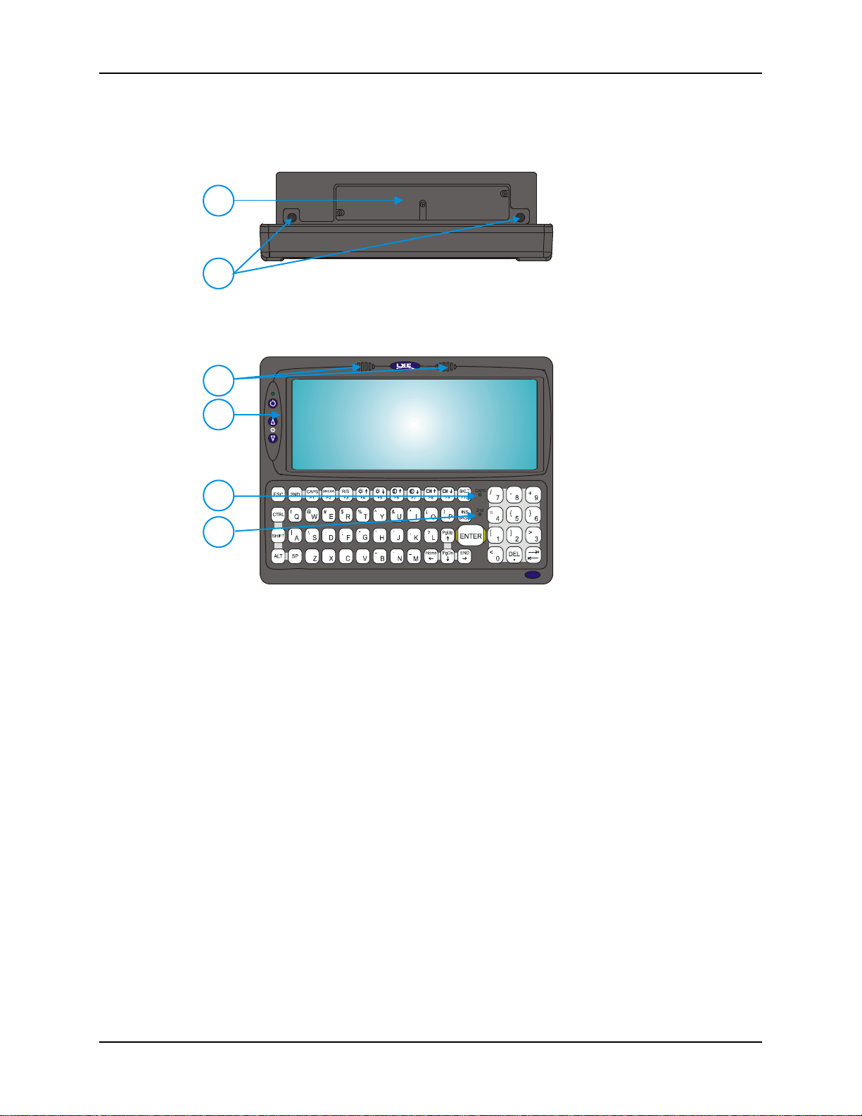
6 Components
V
Components
1
2
Figure 1-1 VX6 Components, Top View
1 Access Panel Cover (See
Following Illustrations for
Detail)
2 Antenna Connectors or
Hole Plugs
1
2
3
4
1. Speakers
2. Control Panel
(See Following
Illustrations for Detail)
3. 2nd Indicator
4. Caps Lock Indicator
X6
Figure 1-2 VX6 Components, Front View
VX6 Reference Guide E-EQ-VX6RG-J
Page 29
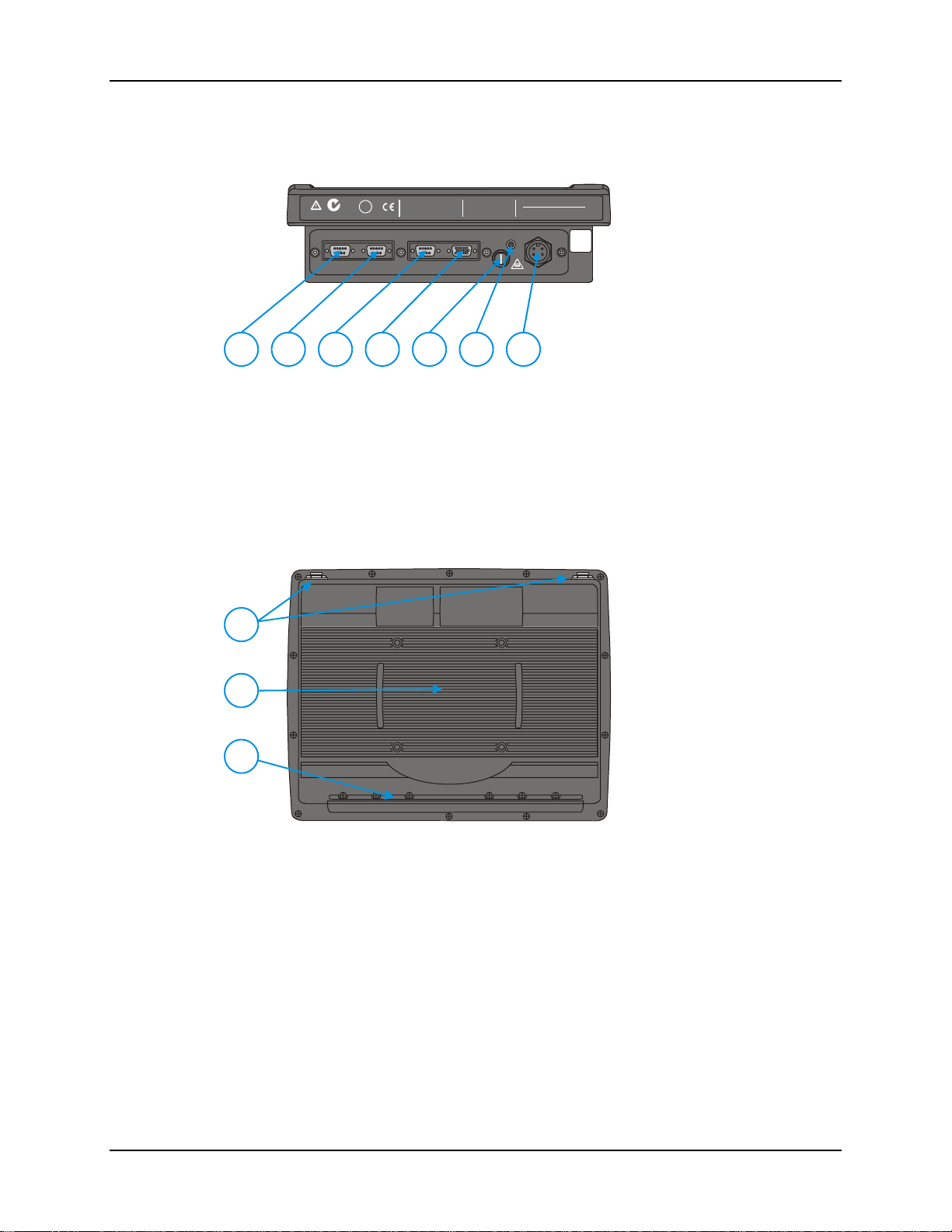
Components 7
1. COM1/Scanner
Connector
IP66
LISTED
I.T.E.
C
REFER TO
MANUAL
E-130794
N107
PRODUCT OF U.S.A. U.S. PATENT 5862393
U
®
L
COM2/3COM1 / SCANNER
US
THIS DEVICE COMPLIES WITH PART 15 OF THE FCC RULES.
OPERATION IS SUBJECT TO THE FOLLOWING TWO
CONDITIONS: (1) THIS DEVICE MAY NOT CAUSE HARMFUL
INTERFERENCE, AND (2) THIS DEVICE MUST ACCEPT ANY
INTERFERENCE RECEIVED, INCLUDING INTERFERENCE
THAT MAY CAUSE UNDESIRED OPERATION.
KEYBOARD /
MOUSE
This Class A digital apparatus complies with
Canadian ICE-003.
Cetappareil num dela ClasseAest
confirme l
ETHERNET /
USB
érique
orme NMB-003 du Canadaà n
AUDIO
CAUTION: For continues protection against risk of fire,
replace only with same type and rating of fuse.
ATTENTION: Pour ne pas compromette la preotection
contre les risques d'incendie, remplacer par un fusible
de mmes types de mmes caractristques nominales.êêé
INPUT:
12-80VDC
6A 72W
T10A, 125V
2. COM3 Connector
3. Keyboard/Mouse
Connector (Not Used)
4. Ethernet/USB Cable
Connector (USB-Host and
USB-Client)
1
3
2
54
7
6
5. Fuse
6. Audio Connector
7. Power Cable Connector
Figure 1-3 VX6 Components, Bottom View
Note: COM1 is configured with Pin 9 +5V. COM3 is labeled “COM2/3” and is configured
with Pin 9 RI. Please see Chapter 4, “Scanner”, for details on configuring Pin 9 of the
serial ports.
1
1. Antenna Connectors
2
2. Bracket Mounting Area
3. Strain Relief Bracket and
Screws
3
Figure 1-4 VX6 Components, Back View
E-EQ-VX6RG-J VX6 Reference Guide
Page 30
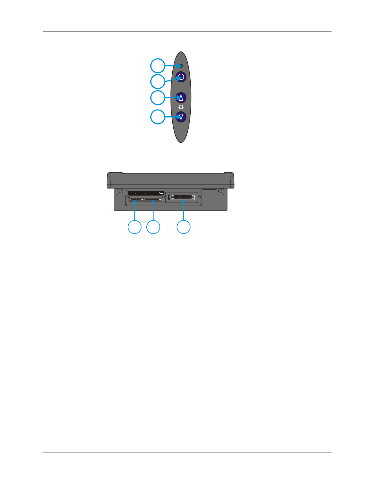
8 Components
SD CF ATA
1
2
3
4
Figure 1-5 VX6 Control Panel
PCMCIA A
PCMCIA B
21
3
Figure 1-6 VX6 Access Panel
1. Power LED
2. Power Switch
3. Brightness Increase
4. Brightness
Decrease
1. SD Memory Card
Slot
2. Compact Flash Hard
Drive
3. PCMCIA Slots
Note: The tethered access panel cover is not shown in the illustration above.
VX6 Reference Guide E-EQ-VX6RG-J
Page 31

Data Entry 9
Data Entry
You can enter data into the VX6 through several different methods. A tethered scanner connected
to the COM1 serial port provides barcode data entry, the serial ports are used to input/output data,
keyboards provide manual entry and the touchscreen also provides manual entry (simulating a
desktop PC’s mouse).
Keyboard Data Entry
Refer to Appendix A “Key Maps” for 101-key keyboard equivalent keypresses.
The keyboard is used to manually input data that is not collected otherwise. Almost any function
that a full sized computer keyboard can provide is duplicated on the VX6 keyboard but it may
take a few more keystrokes to accomplish a keyed task.
Almost every key has two or three different functions. The primary alpha or numeric character is
printed on the key.
nd
For example, when the <2
nd
the <2
character is printed above the corresponding key.
> character i.e. <2nd> + <F1> toggles the CAPS Lock function. The specific <2nd>
> key is selected pressing the desired second-function key produces
Please refer to Appendix A “Key Maps” for instruction on the specific keypresses to access all
PC-compatible keyboard functions.
Tethered Scanners
The VX6 supports an accessory barcode label reading device. Keyboard data entries can be mixed
with barcode data entries. Any scanner that decodes the barcode internally and outputs an RS-232
data stream may be used. COM port 1 is designed to be used with a hand held tethered barcode
scanner.
COM1 is set to +5V on pin 9 up to accept input from a barcode scanner by default. To change
the setting for pin 9, refer to Chapter 4: “Scanner” section titled “Serial Port Pin 9” for details.
Bluetooth Scanners
Bluetooth scanners are paired to the VX6 wirelessly using the VX6 Bluetooth wireless client. The
VX6 does not have a Bluetooth LED.
See following section “Bluetooth” for more information.
Only LXE Bluetooth scanners and LXE Bluetooth printers are supported by LXE. See
Accessories.
RS-232 Data Entry
The VX6 accepts input from an RS-232 device connected to either RS-232 port, COM1 or COM3
(labeled “COM2/3”). The data is entered at the cursor position, and the data is subject to all of the
barcode/RS-232 input menu parameters, such as truncate.
E-EQ-VX6RG-J VX6 Reference Guide
Page 32

10 Data Entry
Touchscreen Entry
Note: The touchscreen should be calibrated before initial use. See “Touchscreen Calibration”
in Chapter 3, “System Configuration”.
Note: Always use the point of the stylus for tapping or making strokes on the display. Never use
an actual pen, pencil or sharp object to write on the touchscreen.
The touchscreen input performs the same function as the mouse that is used to point to and click
elements on a desktop computer. A stylus is used in the same manner as a mouse – single tap or
double tap to select menu options, drag the stylus across text to select, hold the stylus down to
activate slider bars, etcetera.
Hold the stylus as if it were a pen or pencil. Touch an element on the screen with the tip of the
stylus then remove the stylus from the screen. The touchscreen responds to an actuation force
(touch) of up to 4 oz. of pressure.
The touchscreen can be used in conjunction with the keyboard and scanner and an input/output
device connected to one of the VX6’s serial ports.
• Touch the stylus to the field of the data entry form to receive the next data feed.
• The cursor begins to flash in the field.
• The unit is ready to accept data from either the keyboard or a device connected to a
serial port.
Note: The touchscreen may be disabled. Please refer to “MX3-VXC Options” in Chapter 3,
“System Configuration” for details.
Right Click
A right click can be simulated on the touchscreen. To perform a right click, touch the touchscreen
with the stylus and hold it in the same location for a short time.
Note: Some applications may not support this right click method. Please review documentation
for the application to see if it provides for right mouse click configuration.
Input Panel (Virtual Keyboard)
Data may be entered via the input panel (virtual keyboard) on the touchscreen. For more details
on the input panel, please refer to Chapter 2, “Physical Description and Layout”.
VX6 Reference Guide E-EQ-VX6RG-J
Page 33

Data Entry 11
Touchscreen and Mouse
The behavior of the mouse pointer on the touchscreen varies by VX6 construction.
To identify your VX6 platform type, please see “Identifying Your VX6”, in
P
Platform 1 VX6’s
Because the touchscreen also functions as a mouse, the pointer for a USB mouse may not always
be visible on the screen. The mouse pointer reappears when the USB mouse is moved or clicked.
Platform 2 VX6’s
The mouse pointer is not visible unless a USB mouse is attached.
Chapter 2, “Physical Description and Layout”.
• When a USB mouse is first attached to the VX6, the mouse pointer may not be
visible. However, moving or clicking the mouse causes the pointer to appear.
• When the USB mouse is unplugged, the pointer may remain visible until the
touchscreen is tapped.
• If the touchscreen is used for input, the mouse pointer may disappear. However,
moving or clicking the mouse causes the pointer to reappear.
If a mouse is attached, the mouse pointer is displayed on screen.
E-EQ-VX6RG-J VX6 Reference Guide
Page 34

12 Setup the Radio and Network
Setup the Radio and Network
Prerequisites
• Network SSID or ESSID number of the Access Point
• WEP or LEAP Authentication Protocol Keys
See “Chapter 5, “Wireless Network Configuration” for complete information.
Setup Terminal Emulation Parameters
Before you make a host connection, you will, at a minimum, need to know:
• the alias name or IP address (Host Address) and
• the port number (Telnet Port) of the host system
to properly set up your host session.
1. Make sure the mobile client network settings are configured and functional. If you are
connecting over wireless LAN, make sure your mobile client is communicating with the
Access Point.
2. From the Start | Programs, run LXE RFTerm or tap the RFTerm icon on the desktop.
3. Select Session | Configure from the application menu and select the “host type” that you
require. This will depend on the type of host system that you are going to connect to; i.e.
3270 mainframe, AS/400 5250 server or VT host.
4. Enter the “Host Address” of the host system that you wish to connect to. This may either be a
DNS name or an IP address of the host system.
5. Update the telnet port number, if your host application is configured to listen on a specific
port. If not, just use the default telnet port.
6. Select OK
7. Select Session | Connect from the application menu or tap the “Connect” button on the
Command Bar. Upon a successful connection, you should see the host application screen
displayed.
To change options such as Display, Colors, Cursor, Barcode, etc., please refer to the “RFTerm
Reference Guide” on the LXE Manuals CD.
VX6 Reference Guide E-EQ-VX6RG-J
Page 35
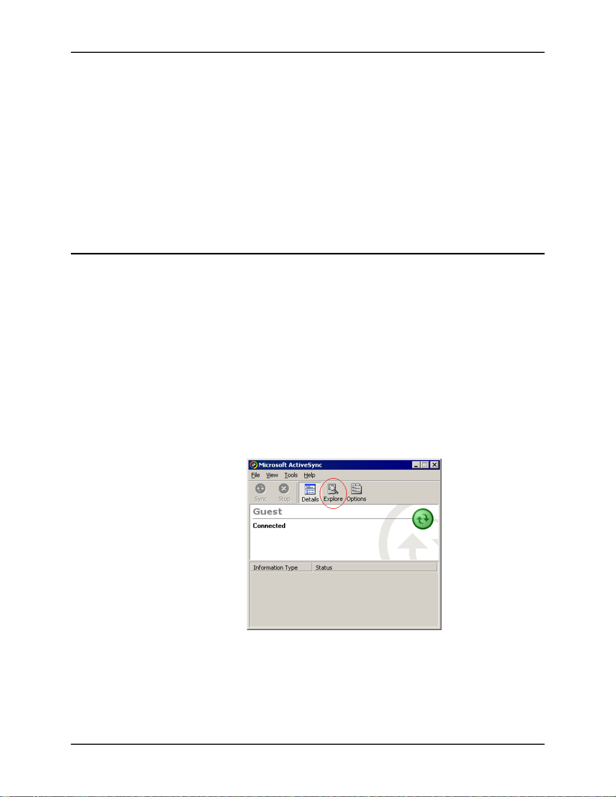
Configuring the VX6 with LXEConnect 13
Configuring the VX6 with LXEConnect
Requirements: ActiveSync version 3.8 (or higher) must be resident on the host (desktop/laptop)
computer. Please see the following section ActiveSync – Initial Setup for more
details on ActiveSync.
ActiveSync is already installed on the VX6. The VX6 is preconfigured to establish a USB
ActiveSync connection to a PC when the proper cable is attached to the VX6 and the PC. If The
VX6 uses a serial port for ActiveSync, it is necessary to configure the VX6 to use the serial port.
Complete details on the proper cables and port configuration are included in the ActiveSync
section later in this chapter.
LXEConnect allows a user to view the VX6 screen remotely from a PC using an ActiveSync
connection.
Install LXEConnect
1. Install Microsoft ActiveSync version 3.8 or higher on a PC with a USB port. For details,
please see ActiveSync later in this chapter.
2. Power up the VX6.
3. Connect the VX6 to the PC using the proper connection cable. Once connected, the
ActiveSync dialog box appears. If using the USB connection, the ActiveSync connection is
automatically established. If using a serial connection, it is necessary to initiate the
connection from the VX6.
4. Select “No” for partnership when prompted. Dismiss any ActiveSync dialog boxes warning a
partnership is not set up. It is not necessary to establish a partnership to use LXEConnect.
However, if a partnership is desired for other reasons, one may be established now. More
details on partnerships are included in ActiveSync later in this chapter.
5. When the ActiveSync screen appears, select Explore.
Figure 1-7 ActiveSync Explore
6. An explorer window is displayed for the VX6. Browse to the \System\LXEConnect folder.
E-EQ-VX6RG-J VX6 Reference Guide
Page 36
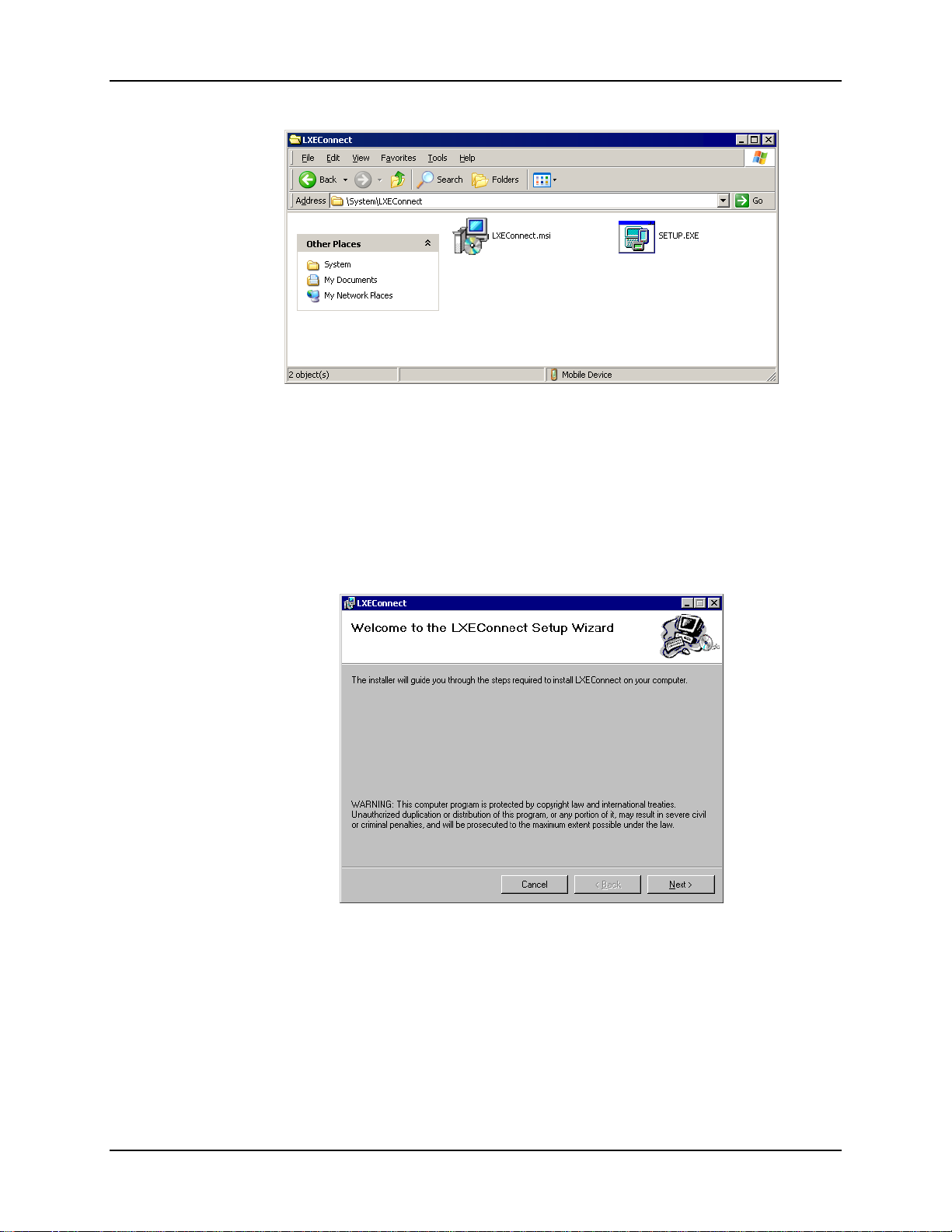
14 Configuring the VX6 with LXEConnect
Figure 1-8 LXEConnect Installation Files
7. Select and copy the LXEConnect.msi and Setup.exe files from the VX6 to the user PC. Note
the location chosen for files
8. Close the ActiveSync explorer dialog box. Do not disconnect the VX6 ActiveSync
connection.
9. Execute the setup.exe file that was copied to the user PC. This setup program installs the
LXEConnect utility.
Figure 1-9 LXEConnect Setup
10. Follow the on screen installation prompts. The default installation directory is C:\Program
Files\LXE\LXEConnect.
11. When the installation is complete, create a desktop shortcut to the following file: C:\Program
Files\LXE\LXEConnect\LXEConnect.exe. If a different directory was selected during
installation, please substitute the appropriate directory.
12. LXEConnect is now installed and ready to use.
VX6 Reference Guide E-EQ-VX6RG-J
Page 37
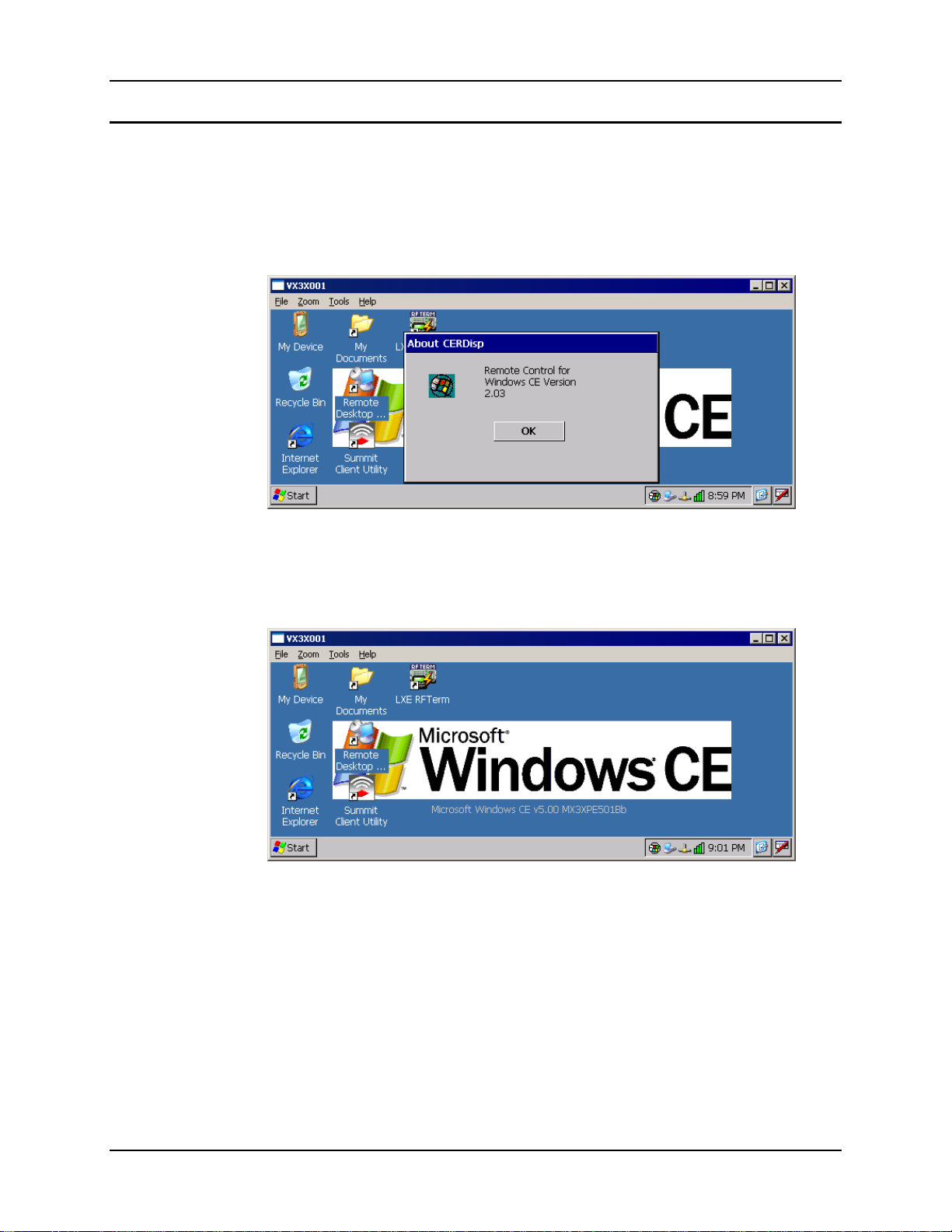
Configuring the VX6 with LXEConnect 15
Using LXEConnect
1. If an ActiveSync connection is has not been established, connect the VX6 to the PC. Details
on ActiveSync are included in the following section.
2. Double-click the LXEConnect icon that was created on the desktop.
3. LXEConnect launches.
Figure 1-10 LXEConnect Notice
4. Click the OK button to dismiss the About CERDisp dialog box. The dialog box
automatically times out and disappears after approximately 30 seconds.
Figure 1-11 LXEConnect Desktop
5. The VX6 can now be configured from the LXEConnect window. Input from the PC’s mouse
and keyboard are recognized as if they were attached to the VX6.
6. When the remote session is completed, terminate the LXEConnect program by selecting File |
Exit or clicking on the X in the upper right hand corner to close the application then
disconnect the ActiveSync cable.
E-EQ-VX6RG-J VX6 Reference Guide
Page 38

16 ActiveSync – Initial Setup
ActiveSync – Initial Setup
The following instructions relate to initial setup of ActiveSync. When there is a Connect icon on
the VX6 desktop, this section can be bypassed.
USB Connection
The VX6 is configured to use USB-C by default. No configuration is necessary
Connect the cable to the PC (the host) and to the dongle cable on the VX6 (the client). The
ActiveSync connection is established automatically when the cable is connected.
Cables for USB ActiveSync Connection:
USB Client to PC/Laptop
Dongle cable w/USB-C
connector
Also requires a standard USB cable with a type A plug on
one end, and a type B plug on the other.
9000A075CBLUSBHCETH
Serial Connection
Select Start | Settings | Control Panel | PC Connection. Click the Change button. From the
popup list, choose the appropriate COM port and baud rate.
Connect
Radio
This will set up the VX6 to use the USB or designated COM port. Click OK and ensure the check
box for “Allow connection with desktop computer when device is attached” is checked.
Click OK to return to the Control Panel.
Note: By default COM3 (labeled “COM2/3”) is configured to use ActiveSync (Pin 9 = RI).
Please refer to “Serial Port Pin 9” in Chapter 4, “Scanner” for details on configuring
Pin 9 of the serial ports.
Connect the correct cable to the PC (the host) and the VX6 (the client). Select “Connect” from the
Start Menu on the VX6 (Start | Programs | Communications | Connect).
Note: Run “Connect” when the “Get Connected” wizard on the host PC is checking COM
ports to establish a connection for the first time.
Cable for Serial ActiveSync Connection:
Serial Client to PC/Laptop RS-232 9 Pin to 9 Pin 9000A054CBL6D9D9
Note: You must establish a partnership with a desktop computer prior to running ActiveSync
on the VX6. The initial partnership must be done using direct serial / USB cable
connection.
Once the relationship is established using the serial port, the ActiveSync link in the Start Menu
gives a choice of connections, one of which is radio.
Select Start | Settings | Programs | Communication | ActiveSync. From the popup list, choose
Network and then click the Connect button.
VX6 Reference Guide E-EQ-VX6RG-J
Page 39
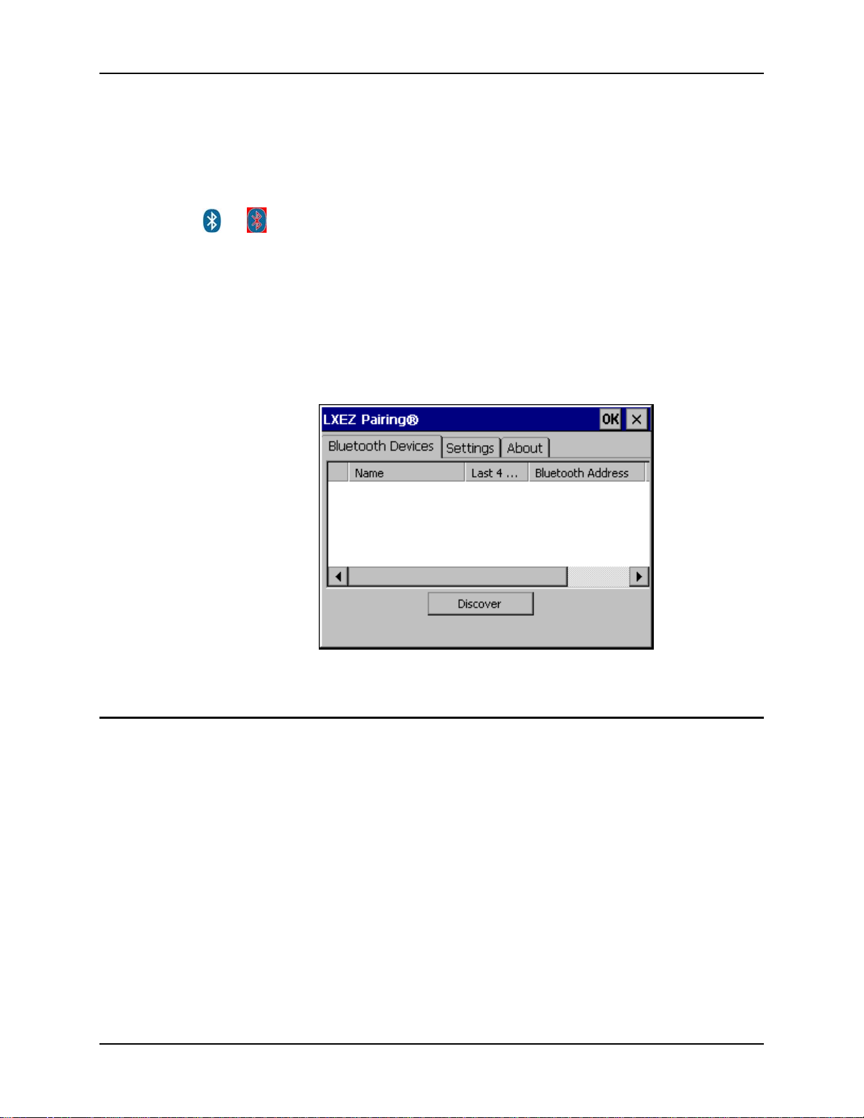
Bluetooth 17
Bluetooth
Access: Start | Settings | Control Panel | Bluetooth or Bluetooth icon
in taskbar or Bluetooth icon on desktop
or
The VX6 default Bluetooth setting is Enabled.
The LXE HX3 Bluetooth
devices. Only LXE printers or scanners are recognized and displayed in the Bluetooth panel. All
other Bluetooth devices are ignored.
Prerequisite The Bluetooth devices (printers and/or scanners) have been setup to allow them
Tap the Bluetooth icon in the taskbar to open the Bluetooth LXEZ Pairing
application.
®
module is designed to Discover and pair with nearby LXE Bluetooth
to be “Discovered” and “Connected/Paired”. The SysAdmin is familiar with the
pairing function of the Bluetooth devices.
Initial Use
Figure 1-12 Bluetooth Devices Display – Before Discovering Devices
1. Select Start | Settings | Control Panel | Bluetooth or tap the Bluetooth icon in the taskbar or
on the desktop.
2. Tap the Settings Tab.
3. Change the Computer Friendly Name at the bottom of the Settings display. The Bluetooth
VX6 default name is determined by the LXE factory installed software version. LXE strongly
urges assigning every VX6 a unique name (up to 32 characters) before Bluetooth Discovery
is initiated.
4. Check or uncheck the VX6 Bluetooth options on the Settings tab.
5. Tap the OK button to save your changes or the X button to discard any changes.
See Also: Chapter 3 – System Configuration, section titled Bluetooth.
E-EQ-VX6RG-J VX6 Reference Guide
Page 40

18 Bluetooth
Settings Tab | Bluetooth Options
Note: These options can still be checked or unchecked whether Bluetooth connection is enabled
or disabled.
As Bluetooth devices pair with the VX6, the name of the device and an icon representing the type
of device is displayed in the Devices window. The icon state changes as the paired Bluetooth
devices connect and disconnect from the VX6. When the Bluetooth devices are disconnected, the
device icon has a red background.
Report when connection lost
A dialog box appears on the VX6 display notifying the user the connection between one (or all) of
the paired Bluetooth devices has stopped. This option is enabled by default.
Click the OK button or the X button to remove the dialog box from the screen.
Report when reconnected
A dialog box appears on the VX6 display notifying the user a connection between one (or all) of
the previously-paired Bluetooth devices is complete. This option is disabled by default.
Click the OK button or the X button to remove the dialog box from the screen.
Report failure to reconnect
If the reconnect timeout (30 minutes) expires, a dialog box appears on the VX6 display notifying
the end-user the connection between one (or all) of the previously-paired Bluetooth devices has
failed. This option is enabled by default.
Click the OK button to remove the dialog box from the screen.
Computer is connectable
There is no dialog connected to this checkbox. Enable this checkbox when you want the VX6 to
be able to pair with other Bluetooth devices. This option is enabled by default.
Computer is discoverable
There is no dialog connected to this checkbox. Enable this checkbox when you want the VX6 to
be Discovered by other Bluetooth devices. This option is disabled by default.
Prompt if devices request to pair
A dialog box appears on the VX6 screen notifying the user a Bluetooth device requests to pair
with the VX6. This option is disabled by default.
The requesting Bluetooth device does not need to have been Discovered by the VX6 before the
pairing request is received.
Click the Accept button or the Decline button to remove the dialog box from the screen.
VX6 Reference Guide E-EQ-VX6RG-J
Page 41

Bluetooth 19
Continuous search
When enabled, the VX6 never stops searching for a device it has paired with once the connection
is broken (such as the paired device entering Suspend mode, going out of range or being turned
off).
When disabled, the VX6 stops searching after one half hour. The search can be restarted by
putting the VX6 through a Suspend/Resume cycle or accessing the Bluetooth control panel.
This option is disabled by default.
Subsequent Use
Note: Taskbar and Bluetooth device Icon states change as Bluetooth devices are discovered,
pair, connect and disconnect. A taskbar Bluetooth icon with a red background indicates
Bluetooth is active and not paired with any device. A device icon with a red background
indicates a disconnected paired device.
1. Tap the Bluetooth icon in the taskbar or on the desktop to open the Bluetooth LXEZ Pairing
application.
2. Tap the Bluetooth Devices tab.
3. Tap the Discover button. When the Bluetooth module begins searching for in-range
Bluetooth devices, the button name changes to Stop. Tap the Stop button to cancel the
Discover function at any time.
4. The discovered devices are listed in the Bluetooth Devices window.
5. Doubletap a Bluetooth device in the Discovered window to open the device properties menu.
6. Tap Pair as Scanner to set up the VX6 to receive scanner data.
7. Tap Pair as Printer to set up the VX6 to send data to the printer.
8. Tap Disconnect to stop pairing with the device. Once disconnected, tap Delete to remove the
device name and data from the VX6 Bluetooth Devices list. The device is deleted after the
user taps OK..
9. Upon successful pairing, the selected device may react to indicate a successful connection.
The reaction may be an audio signal from the device, flashing LED on the device, or a dialog
box is placed on the VX6 display.
10. Whenever the VX6 is turned On, all previously paired, live, Bluetooth devices in the vicinity
are paired, one at a time, with the VX6. If the devices cannot connect to the VX6 before the
re-connect timeout time period expires (default is approximately 20 seconds for each paired
device) there is no indication of the continuing disconnect state if Report Failure to
Reconnect is disabled.
See Also: Chapter 3 – System Configuration, section titled Bluetooth.
E-EQ-VX6RG-J VX6 Reference Guide
Page 42
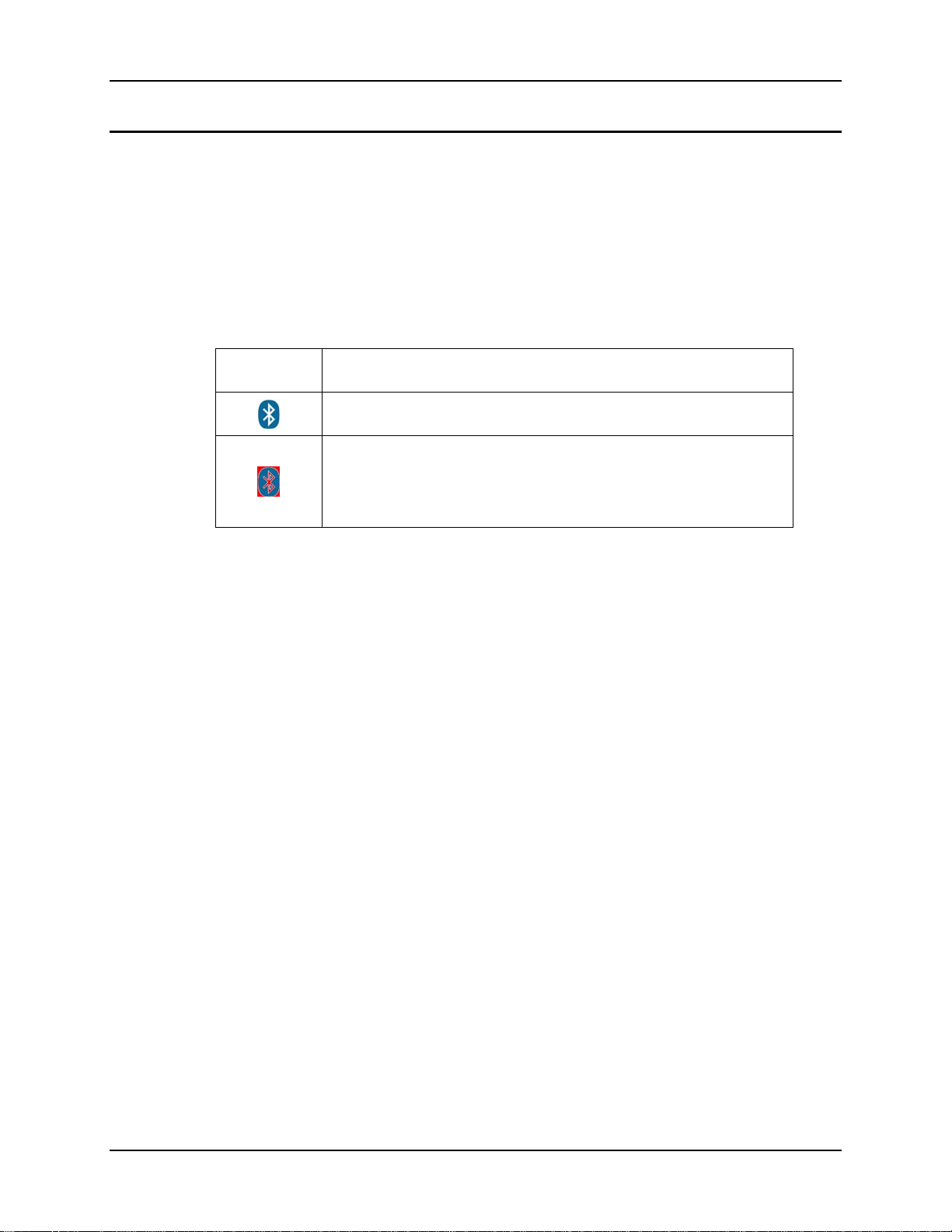
20 Bluetooth
Bluetooth Devices
Assumption: The System Administrator has Discovered and Paired targeted Bluetooth devices
for each VX6. The System Administrator has also enabled / disabled Bluetooth
settings and assigned a Computer Friendly Name for each VX6. See Chapter 3
System Configuration, Bluetooth control panel applet and supported Bluetooth
printers and scanners.
The Bluetooth taskbar Icon state and Bluetooth LED states change as Bluetooth devices are
discovered, pair, connect and disconnect. There may be audible or visual signals as paired devices
re-connect with the VX6. Only LXE printers or scanners are recognized and displayed in the
Bluetooth panel. All other Bluetooth devices are ignored.
Taskbar
Icon
Note: When an active paired device enters Suspend Mode, is turned Off or leaves the VX6
Bluetooth scan range, the Bluetooth connection between the paired device and the VX6 is
lost. There may be audible or visual signals as paired devices disconnect from the VX6.
See Accessories for supported Bluetooth printers and scanners.
AppLock, if installed, does not stop the end-user from using Bluetooth applications, nor does it
stop authorized Bluetooth-enabled devices from pairing with the VX6 while AppLock is in
control. See Chapter 6 – AppLock for more information.
See Also: Chapter 3 – System Configuration, section titled Bluetooth.
Legend
Bluetooth module is connected to one or more of the targeted Bluetooth
device(s).
VX6 is not connected to any Bluetooth device.
VX6 is ready to connect with any Bluetooth device.
VX6 is out of range of all paired Bluetooth device(s). Connection is
inactive.
VX6 Reference Guide E-EQ-VX6RG-J
Page 43
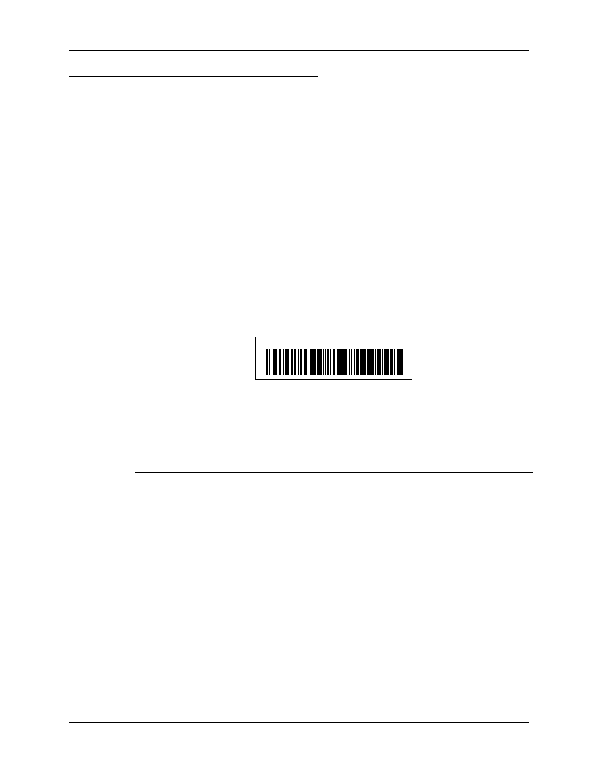
Bluetooth 21
Bluetooth Barcode Reader Setup
Please refer to the Bluetooth scanner manufacturer’s User Guide; it may be available on the
manufacturer’s web site. Contact your LXE representative for Bluetooth product assistance.
Introduction
LXE supports several different types of barcode readers. This section describes the interaction and
setup for a mobile Bluetooth laser scanner or laser imager connected to the VX6 using Bluetooth
functions.
• The VX6 must have the Bluetooth hardware and software installed. An VX6 operating
system upgrade may be required. Contact your LXE representative for details.
• If the VX6 has a Bluetooth address identifier barcode label affixed, then Bluetooth
hardware and software is installed.
• The mobile Bluetooth laser scanner / laser imager battery is fully charged.
• The barcode numbering examples in this segment are not real and should not be created
nor scanned with a Bluetooth scanner.
• To open the LXEZ Pairing program, tap Start | Settings | Control Panel | Bluetooth or
tap the Bluetooth icon on the desktop or tap the Bluetooth icon in the taskbar.
Locate the barcode label, similar to the one shown above, attached to the mobile device. The label
is the Bluetooth address identifier for the VX6.
The mobile Bluetooth scanner / imager requires this information before discovering, pairing,
connecting or disconnecting can occur.
Important: The VX6 Bluetooth address identifier label should remain protected from damage
(rips, tears, spills, soiling, erasure, etc.) at all times. It may be required when pairing, connecting,
and disconnecting new Bluetooth barcode readers.
VX6 with Label
If the VX6 has a Bluetooth address barcode label attached, follow these steps:
1. Scan the Bluetooth address barcode label, attached to the VX6, with the LXE Bluetooth
2. If this is the first time the Bluetooth scanner has scanned the VX6 Bluetooth label, the devices
LnkB00440fd01020 - Sample
Figure 1-13 Sample Bluetooth Address Barcode Label
mobile scanner.
are paired. See section titled “Bluetooth Beep and LED Indications”. If the devices do not
pair successfully, go to the next step.
3. Open the LXEZ Pairing panel [Start | Settings | Control Panel | Bluetooth].
4. Tap Discover. Locate the Bluetooth scanner in the Discovery panel.
5. Doubletap the stylus on the Bluetooth scanner. The right-mouse-click menu appears.
6. Select Pair as Scanner to pair the VX6 with the Bluetooth mobile scanner.
E-EQ-VX6RG-J VX6 Reference Guide
Page 44
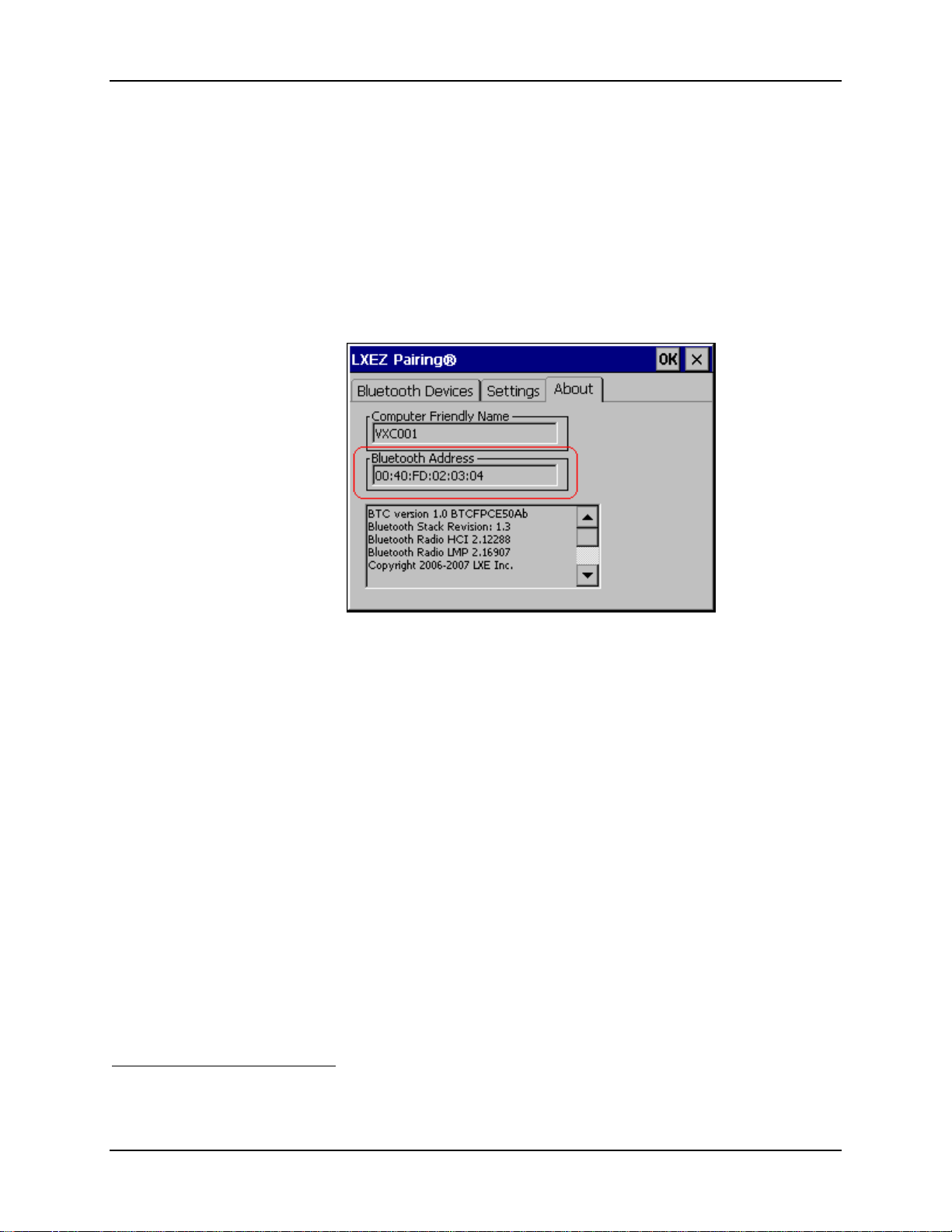
22 Bluetooth
The devices are paired. The Bluetooth barcode reader responds with a series of beeps and LED
flashes. Refer to the following section titled “Bluetooth Beep and LED Indications”.
Note: After scanning the VX6 Bluetooth label, if there is no beep and no LED flash from the
Bluetooth device, the devices are currently paired.
VX6 without Label
If the VX6 Bluetooth address barcode label does not exist, follow these steps to create a unique
Bluetooth address barcode for the VX6:
First, locate the VX6 Bluetooth address by tapping Start | Settings | Control Panel | Bluetooth |
About tab.
Figure 1-14 About tab and Bluetooth Address
1
Next, create a Bluetooth address barcode label for the VX6
.
The format for the barcode label is as follows:
• Barcode type must be Code 128.
• FNC3 character followed by string Uppercase L, lowercase n, lowercase k, uppercase B
and then the Bluetooth address (12 hex digits, no colons). For example,
LnkB0400fd002031.
Create and print the label.
Scan the VX6 Bluetooth address barcode label with the Bluetooth barcode reader.
The devices are paired. The Bluetooth barcode reader responds with a series of beeps and LED
flashes. Refer to the following section titled “Bluetooth Beep and LED Indications”.
Note: After scanning the VX6 Bluetooth label, if there is no beep and no LED flash from the
Bluetooth device, the devices are currently paired.
1
Free barcode creation software is available for download on the World Wide Web. Search
using the keywords “barcode create”.
VX6 Reference Guide E-EQ-VX6RG-J
Page 45

Bluetooth 23
Bluetooth Beep and LED Indications
Beep Type from Bluetooth Device Behavior
Acknowledge label 1 beep
Label rejected 2 beeps at low frequency
Transmission error Beep will sound high-low-high-low
Link successful Beep will sound low-medium-high
Link unsuccessful Beep will sound high-low-high-low
LED on Bluetooth Device Behavior
Yellow LED blinks at 2 Hz Linking in progress
Off Disconnected or unlinked
Yellow LED blinks at 50 Hz Bluetooth transmission in progress
Yellow LED blinks at the same rate
as the paging beep (1 Hz)
Green LED blinks once a second Disabled indication
Upon startup, if the scanner sounds a long tone, this means the scanner has not passed its
automatic Selftest and has entered isolation mode. If the scanner is reset, the sequence is repeated.
Contact LXE Support for assistance.
Paging
E-EQ-VX6RG-J VX6 Reference Guide
Page 46

24 Saving Changes to the Registry
Saving Changes to the Registry
The VX6 saves the registry when you:
• Tap the Start | Run then type Warmboot. Tap OK.
• Install Restart in the Start menu by Start | Run then type CTL RESTART=1 and tap the
OK button. Tap Start | Restart.
The registry save process takes 0 – 3 seconds. If nothing has been changed, nothing is saved (e.g.
0 seconds)
The registry is automatically saved every 20 minutes. It is also saved every tenth time the registry
settings are changed. Registry settings are changed when control panel applet (e.g. Date/Time)
parameters are changed by the user and a warm boot was not performed afterward.
When you tap the Start | Run then type Coldboot and tap the OK button, factory default registry
settings are loaded during coldboot. All changes and settings are lost.
VX6 Reference Guide E-EQ-VX6RG-J
Page 47

Getting Help 25
Getting Help
All LXE manuals are now available on one CD and they can also be viewed/downloaded
from the LXE website. Contact your LXE representative to obtain the LXE Manuals CD.
You can also get help from LXE by calling the telephone numbers listed on the LXE Manuals
CD, in the file titled “Contacting LXE”. This information is also available on the LXE website
www.lxe.com.
Explanations of terms and acronyms used in this guide are located in the file titled “Glossary” on
the LXE Manuals CD.
Manuals and Accessories
Manuals
The following manuals are available on the LXE Manuals CD:
Accessories
• VX6 User’s Guide
• RFTerm
®
Reference Guide
• Contacting LXE
• LXE Technical Glossary
The table below lists the available VX6 accessories.
• Where two parts numbers are listed for a given part, the part number ending in “-R”
is the RoHS compliant version.
• When only one part number is listed, the part is RoHS compliant unless otherwise
noted.
VX6 Brackets
Bracket, U Style, VX6 VX77 9000A021UBRACKET-R
Kit, VXX U-Bracket to VX6 VX7 Adapter 9000A022BRKTADPTKIT-R
Bracket, RAM Mount VX6 VX7 9000A023BRKTRAMMOUNT-R
Bracket, VXX RAM ball on plate 9000A028RAMPLATEBALL-R
Bracket, RAM Squeeze Mount, VX6 VX7 9000A031BRKTRAMSQZMT-R
Bracket, RAM Backup Mounting Plate 9000A033BACKUPPLATE
Data Cables
Cable, Combo D15 to USB and Ethernet Adapter 1 Ft 9000A071CBLD15USBETH
Cable, Combo D15 to USB-H, USB-C and Ethernet Adapter 9000A075CBLUSBHCETH
Cable, Printer/PC, D9 to D25
Cable, PC, D9 to D9 9000A054CBL6D9D9
Power Cables
Cable, Input Power, 12 FT, VX5 VX6 VX7 9000A073CBLPWR12FT-R
Adapter Cable, VX1 VX2 VX4 Power Cable to VX5 VX6 VX7 9000A077CBLPWRADPTR
9000A053CBL6D9D25
(above part is not RoHS compliant)
E-EQ-VX6RG-J VX6 Reference Guide
Page 48

26 Manuals and Accessories
Power Supplies
Power Supply, External, AC, W/US Power Cord VX5 VX6 VX7 9000A317PSACUS-R
Power Supply, External, AC, No Power Cord VX5 VX6 VX7 9000A318PSACWW-R
UPS Battery and Cables
Battery, UPS Lead Acid, VX5 VX6 VX7 9000A378UPSBATTPACK-R
Cable, UPS Battery, Remote Mount Extender, 6 Ft 9000A074CBLUPSEXTNDR
Antenna and Antenna Mount Kits
Replacement antenna, 2.4GHz 153180-0001
Remote Mount Antenna Kit, 8 Ft Cable, b/g 9000A279ANTREMOTE8-R
Remote Mount Antenna Kit, 8 Ft Cable, a/b/g 9000A283RMTAGANT8
Remote Mount Antenna Kit, 6 Ft Cable, b/g 9000A278ANTREMOTE6-R
Remote Mount Antenna Kit, 6 Ft Cable, a/b/g 9000A282RMTAGANT6
Right Angle Remote Mount Antenna Kit, 6 Ft Cable, b/g 9000A280ANTREMOTE6RT
Right Angle Remote Mount Antenna Kit, 6 Ft Cable, a/b/g 9000A284RMTAGANT6RT
Right Angle Remote Mount Antenna Kit, 15 Ft Cable, b/g 9000A281ANTREMOT15RT
Right Angle Remote Mount Antenna Kit, 15 Ft Cable, a/b/g 9000A285RMTAGANT15RT
Miscellaneous
Stylus, with Tethers and Sleeves, 5 Pack 9000A510STYLUS
Protective Film, Touchscreen, 10 Pack, VX6 VX6A512PROTFILM
Voice Recognition Accessories
Headset coiled adapter cable, with quick disconnect connector to a
2.5 mm audio jack. A headset (see below) is required
Headset, Single Band HX1A501SINGHEADSET
Headset, Dual Band HX1A502DUALHEADSET
Headset, Behind the Ear, Dual Ear HX1A503BTHHEADSET
Foam, Replacement Block, Headset HX1A504HSBLOCKFOAM
Yoke, Replacement for Dual Band Headset HX1A505DUALYOKE
Yoke, Replacement for Single Band Headset HX1A506SINGLEYOKE
Replacement Microphone Foam, Wind Screen, 10 pack HX1A508WINDSREEN10
Replacement Microphone Foam, Wind Screen, 50 pack HX1A509WINDSREEN50
Replacement Headset Foam, Ear Cover, 10 pack HX1A510FOAMEAR10
Replacement Headset Foam, Ear Cover, 50 pack HX1A511FOAMEAR
9000A076CBLHEADSET1
VX6 Reference Guide E-EQ-VX6RG-J
Page 49

Manuals and Accessories 27
Scanners
Scanner, Powerscan, SR, 8’ Cbl, WW
Scanner, Powerscan, SR, 12’ Cbl, US
Scanner, Powerscan, SR, Low Temp, 8’ Cbl
Scanner, Powerscan, SR, Low Temp, 12’ Cbl
Scanner, Powerscan, LR, 8’ Cbl, WW
Scanner, Powerscan, LR, 12’ Cbl, US
Scanner, Powerscan, LR, Low Temp, 8’ Cbl
Scanner, Powerscan, LR, Low Temp, 12’ Cbl
Scanner, Powerscan, XLR, 8’ Cbl, WW
Scanner, Powerscan, XLR, 12’ Cbl, US
Scanner, Powerscan, XLR, Low Temp, 8’ Cbl
Scanner, Powerscan, XLR, Low Temp, 12’ Cbl
Scanner, LS3408 Fuzzy Logic SR, D9 Interface Cable, 8ft
Scanner, LS3408 Extended Range, D9 Interface Cable, 8ft 520A326SCNRERDA9F-R
8300A326SCNRPWRSR8DA9F
8300A326SCNRPWRSR8DA9F-R
8300A327SCNRPWRSR12DA9F
(above part is not RoHS compliant)
8300A332SCNRS8D9FLT
(above part is not RoHS compliant)
8300A333SCNRS12D9FLT
(above part is not RoHS compliant)
8310A326SCNRPWRLR8DA9F
8310A326SCNRPWRLR8DA9F-R
8310A327SCNRPWRLR12DA9F
8310A327SCNRPWRLR12DA9F-R
8310A332SCNRL8D9FLT
(above part is not RoHS compliant)
8310A333SCNRL12D9FLT
(above part is not RoHS compliant)
8320A326SCNRPWRXLR8DA9F
8320A326SCNRPWRXLR8DA9F-R
8320A327SCNRPWRXLR12DA9F
(above part is not RoHS compliant)
8320A332SCNRX8D9FLT
(above part is not RoHS compliant)
8320A333SCNRX12D9FLT
(above part is not RoHS compliant)
8510A326SCNRFZYDA9F
8510A326SCNRFZYDA9F-R
E-EQ-VX6RG-J VX6 Reference Guide
Page 50

28 Manuals and Accessories
Bluetooth Scanner and Accessories
LXE Bluetooth module with laser ring scanner, battery, two
hand/wrist straps (large and small)
LXE Bluetooth module with 1D/2D imager ring scanner,
battery, two hand/wrist straps (large and small)
Li-Ion Spare Battery for LXE Bluetooth Ring Scanner
Module
8651A100BTLASERKIT
8652A100BTIMAGERKIT
8650A376BTBOHBATTERY
LXE 8-bay battery charger with US power cord 8650A377BTBOHCHGRUS
LXE single-bay charger with US wall plug 8651A379SINGLECHGRUS
PowerScan 7000BT Scanner RS-232 with pointer 8700A301SCNRBTSRI
PowerScan 7000BT Base Station, RS232, without universal
power supply.
PowerScan 7000BT Base Station Power Supply, Std US, 120V 8700A502PSACUS
PowerScan 7000BT, RS232 Cable for Base Station, DB9S, Coil,
8’
PowerScan 7000BT Battery Charger with Power Supply, Four
Station, US Std
PowerScan 7000BT Battery Pack 8700A504BATT
Bluetooth Standard Range Fuzzy Logic laser scanner
Bluetooth Auto range “LORAX” scanner
Desk Cradle, Radio/Charging, Multi-Interface
Desk Cradle, Charge Only, Mulit-Interface
Forklift Cradle, Radio/Charging, Multi-Interface
Forklift Cradle, Charge Only, Multi-Interface
US AC Power Cord
Universal Desktop Power Supply 90-264VAC
9-60VDC Forklift Power Supply
Power Cable (connects Power Supply to Forklift)
Cable Assembly, DA9F, 9 ft, Cradle to Terminal
Forklift Rugged Scanner Holder with RAM mount
8800 Spare Battery
Single slot Universal Battery Charger Adapter Cup
Single Slot Battery Charger w/International Power
Universal Battery Charger, 4 slot. Requires 4 adapter cups
Scanner Holster for Belt
Mounted take up Reel 8000A501INDREEL
Auto Sense Intellistand, Hands Free Scanning
Strap with Scanner Clip
8700A501BASERS232
8700A001CBL8DA9F
8700A503CHGR4US
8810A326SCNRBTFZ
8820A327SCNRBTER
8800A001CRADLERCMI
8800A002CRADLECMI
8800A003CRADLEVRCMI
8800A004CRADLEVCMI
8800A051POWERCORD
8800A301ACPS
8800A302DCPS
8800A052DCPWRCABLE
8500A051CBL9DA9F
8800A005STAND
8800A376BATTERY
8800A377CHGRADPTRCUP
8800A378CHGR1SLOT
8800A379CHGRBASE
8200A501HOLSRBELT
8500A505STANDSMT
9000A411SCNRSTRAP
VX6 Reference Guide E-EQ-VX6RG-J
Page 51

Chapter 2 Physical Description and Layout
Identifying Your VX6
Some features discussed in this document may not be available for all VX6’s. Additionally, some
features require a certain revision level of system software.
Any feature that is not identified as platform specific or requiring a certain level of system
software is available to all VX6’s.
Hardware Platforms
P
Platform 1 VX6
VX6’s identified as Platform 1 by a P1 notation on the serial number decal (and VX6’s with no
platform identification on the serial number decal) are referred to as Platform 1 VX6’s. These
VX6’s DO NOT support the features identified as “Platform 2” throughout this manual.
To determine the platform level of your VX6, please refer to the VX6 serial
number decal.
Note: If software revision 1ED or greater is installed, “LXE VX6 Platform 1” is displayed
Platform 2 VX6
VX6’s identified as Platform 2 by a P2 notation on the serial number decal support all features,
including those noted as Platform 2 specific.
Note: If software revision 1ED or greater is installed, “LXE VX6 Platform 2” is displayed
Software Revisions
S
The software revision is displayed during boot up and on the default desktop wallpaper. The
revision can also be viewed using the Start | Settings | Control Panel | About icon. For more
information, please refer to Chapter 3, “System Configuration”.
To upgrade the VX6 with a newer revision of system software, please refer to “Reflash the VX6”
in Chapter 3, “System Configuration”.
during boot up. See “Software Revisions”, below, to determine the software revision
installed on the VX6. If no software revision is displayed during bootup, the VX6 is a
Platform 1 type as all Platform 2 VX6’s ship with software revision 1ED or greater.
during boot up. See “Software Revisions”, below, to determine the software revision
installed on the VX6.
Some features described in this manual require a certain minimum revision level of
system software. These features are available on all VX6’s if the proper revision
level (or newer) of system software is installed.
E-EQ-VX6RG-J VX6 Reference Guide
Page 52
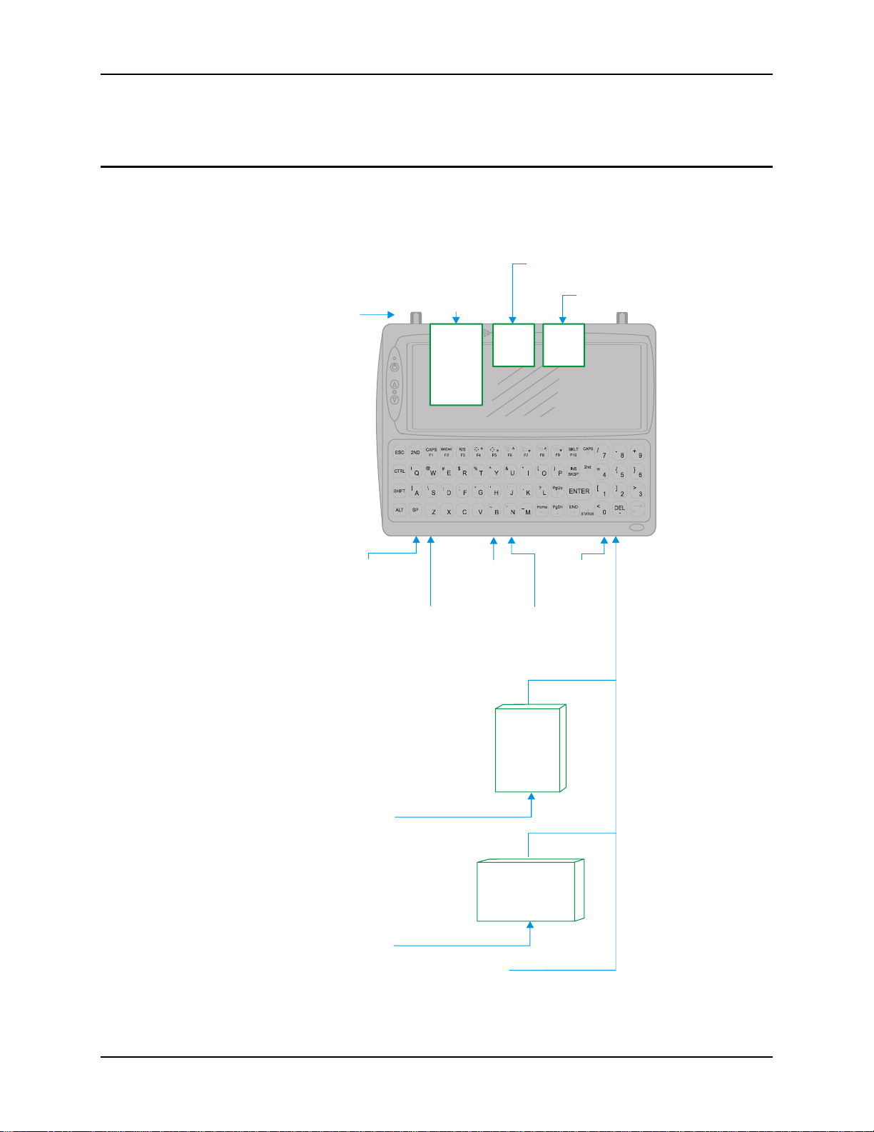
30 Hardware Configuration
V
Hardware Configuration
System Hardware
The VX6 hardware configuration is shown in the following figure.
Compact
CF
Slot
Flash
Hard
Drive
Slot
Secure Digital
Memory Card
SD
Antenna
Connector
Any Type
I, II or III
PCMCIA
Card
Slot A
&
Slot B
Serial
Connector
COM1 - Scanner
(9 pin male "D")
COM3 - PRINTER/PC
(9pin male "D")
Keyboard/
Mouse
Connector
(Not Used)
Serial
Connector
AC in (120 - 240V)
DC in (12-80V)
USB/
Ethernet
Connector
DC out (12V)
AC Adapter
Uninterruptible
Power
Supply (UPS)
DC in (12-80V)
X6
Audio
Connector
Figure 2-1 VX6 Hardware Configuration
VX6 Reference Guide E-EQ-VX6RG-J
Page 53

Hardware Configuration 31
Central Processing Unit
The LXE VX6 contains a 400MHz Intel PXA255 CPU.
I/O Components
The VX6 supports the following I/O components:
• Two 9-pin RS-232 serial ports configured as:
o COM1
o COM3 (labeled “COM2/3”)
Note: There is no COM2 port on the VX6.
• Two PCMCIA slots (supporting Type I or II PCMCIA cards).
• One slot for SD memory card.
• Compact flash drive.
• Integrated QWERTY keyboard.
• Ports available via dongle cable:
o USB Host port
System Memory
Main system memory is 128MB DRAM.
Note: The 64MB SDRAM option has been discontinued.
Video Subsystem
The LXE VX6 video subsystem consists of a color TFT display. The video subsystem complies
with the VESA VL bus standard. The resolution of this display is 800 by 320 pixels. This
resolution complies with the SVGA graphics industry standard.
The display supports screen blanking to eliminate driver distraction when the vehicle is in motion.
Please see “Technical Specifications – Screen Blanking Cable” later in this chapter and “Screen
Blanking” in Chapter 4, “Scanner” for details.
o USB Client port
o Ethernet port
• One audio jack providing monaural audio output.
E-EQ-VX6RG-J VX6 Reference Guide
Page 54

32 Hardware Configuration
Power Supply
Vehicle power input for the VX6 is 12V to 80V DC nominal and is accepted without the need to
perform any manual operation within the VX6.
If 12V to 60V DC power is not available – for example, in an office environment – an optional
external Universal Input Power Supply can be used to convert AC wall power to an appropriate
DC level. See “External Power Supply”, later in this chapter.
Power input is fused for protection and the fuse is externally accessible.
Uninterruptible Power Supply
A DC uninterruptible power supply (UPS) battery is available to maintain power to the VX6 for a
minimum of 15 minutes when vehicle power is not available (such as when a vehicle battery is
being swapped).
Backup Battery
The LXE VX6 has a permanent lithium battery installed to maintain time and date. The backup
battery is not user serviceable and should last five years with normal use before it requires
replacement.
Note: This battery should only be changed by authorized service personnel.
PCMCIA Slots
Microsoft Windows CE Plug and Play operating system controls the PCMCIA cards. These cards
are hot swappable per the PCMCIA specifications.
CF Slot
The CF ATA slot is not hot swappable. The VX6 must be powered down to insert or remove an
ATA card. Since the operating system is stored on the ATA card, the VX6 cannot operate
without the ATA card.
SD Slot
The SD slot accepts an SD memory card. These cards are hot swappable.
VX6 Reference Guide E-EQ-VX6RG-J
Page 55

Hardware Configuration 33
Bluetooth LXEZ Pairing
The VX6 contains Bluetooth version 2.0 with Enhanced Data Rate (EDR) up to 3.0 Mbit/s over
the air. Bluetooth device connection (or pairing) can occur at distances up to 32.8 ft (10 meters)
Line of Sight. The wireless client retains wireless connectivity while Bluetooth is active.
The user will not be able to select PIN authentication or encryption on connections from the HX3.
However, the HX3 supports authentication requests from pairing devices. If a pairing device
requests authentication or encryption, the VX6 displays a prompt for the PIN or passcode.
Maximum encryption is 128 bit. Encryption is based on the length of the user’s passcode.
Bluetooth will simultaneously support one printer as a slave Bluetooth device and one scanner,
either as a slave or as a master Bluetooth device.
See Chapter 3 System Configuration, control panel section titled Bluetooth.
Notes
• The VX6 does not have a Bluetooth managed LED.
• The LED on the Bluetooth scanner illuminates during a scanning operation.
• Barcode data captured by the Bluetooth scanner is manipulated by the settings in the VX6
Scanner Properties control panel applet.
• Multiple beeps may be heard during a barcode scan using the Bluetooth scanner; beeps
from the Bluetooth scanner as the barcode data is accepted/rejected, and other beeps from
the VX6 during final barcode data manipulation.
E-EQ-VX6RG-J VX6 Reference Guide
Page 56

34 Power Modes
Power Modes
The VX6 has several distinct power modes.
• On Mode – When the VX6 is attached to either vehicle 12-80 VDC or an external
power supply and the power button is pressed, the VX6 is in the On mode. In this
mode, the keypad, touchscreen and any attached peripherals such as a scanner
function normally. The display remains on until the backlight timer (if enabled)
expires.
• User Idle Mode – If the Display Backlight Timer is enabled (see the Display section
in the Windows CE Control panel), the VX6 enters User Idle Mode when the display
backlight timer expires without any Primary Event (see below) to reset the timer.
The VX6 exits User Idle Mode with any Primary Event. The keypress or screen
touch that exits User Idle Mode is sent to the operating system. The VX6 then
transitions to On Mode.
Primary Events
Any key on the keypad COM1 activity
Stylus touch on the touchscreen Scanner activity
Power button tap USB client connection
Bluetooth device reconnect / disconnect message
• System Idle Mode – The VX6 does not support System Idle mode.
• Suspend Mode – TheVX6 does not support Suspend mode. However, if the
Suspend timer is enabled, the VX6 transitions to Off mode when the Suspend timer
expires.
• Off Mode – The VX6 turns off if the user presses the power button when the VX6 is
On. The VX6 is also off when it is not connected to a power source. However, an
internal Real Time Clock (RTC) powered by an internal battery maintains the date
and time while the VX6 is off.
VX6 Reference Guide E-EQ-VX6RG-J
Page 57
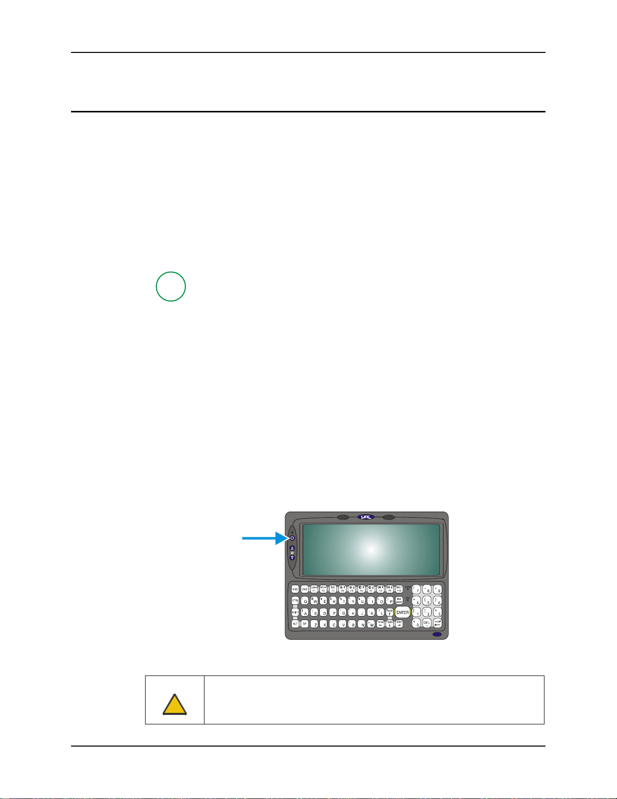
Physical Controls 35
V
Physical Controls
On/Off Switch
The power (on/off) switch is a push button switch located on the front control panel of the VX6.
The switch is a momentary switch. If the VX6 is Off, pressing the power switch turns the VX6
On.
For Platform 2 VX6’s, the keyboard LEDs turn on for about one second when the operating
system loads the keyboard driver. If the LEDs blink more than once, this indicates a keyboard
problem.
• On an external USB keyboard, the NumLock, CapsLock and Scroll Lock keys blink
the same as a desktop PC.
• On the 60-key keyboard, only the CAPs led is lit during this process.
To identify your VX6 platform type, please see “Identifying Your VX6”, earlier in
P
If the VX6 is On, pressing and releasing the power switch turns the VX6 Off. An orderly
shutdown is preformed. Any open programs are closed, the Windows CE operating system shuts
down and then the VX6 powers off.
this chapter.
If a software lockup should occur and the VX6 is unresponsive to keyboard or touchscreen input,
pressing and holding the power button for several seconds forces a shutdown. However, the
forced shutdown is not an orderly shutdown. All unsaved data and any registry settings not saved
to persistent storage are lost.
The Status LED, located on the keyboard of the VX6, is lit when the power is on:
• Green – VX6 is operating from vehicle power or AC power.
• Solid Yellow – VX6 is operating from the UPS, UPS battery is good.
• Flashing Yellow – VX6 is operating from the UPS, UPS battery is critically low.
Note: Always turn the computer off prior to removing power cables.
X6
Figure 2-2 The Power (On/Off) Switch
Caution
The VX6 has voltage on it even when power is off. Always disconnect input
!
power before working on the VX6 (changing fuse, opening access panel,
etc).
E-EQ-VX6RG-J VX6 Reference Guide
Page 58

36 External Connectors
External Connectors
Most external connectors for the VX6 are located on the bottom of the unit.
• The Keyboard/Mouse connector is not used on the VX6 as the VX6 contains an
integrated keypad.
• COM1 connects to a serial barcode scanner.
• COM3 (labeled “COM2/3”) connects to a serial printer or PC with the appropriate
cables.
• The USB/Ethernet connector accepts dongle cables, offering a combination of the
following ports:
o An Ethernet port
o A USB Host port
o A USB Client port.
• Audio connects to a mono or stereo telephone headset/microphone.
Other external connectors are located as follows:
• Antenna connectors are located on the top of the VX6. VX6’s can be configured for
a single antenna or dual antennas.
VX6 Reference Guide E-EQ-VX6RG-J
Page 59

External Connectors 37
Scanner Serial Connector (COM1)
The serial connector, labeled “SCANNER”, (configured as COM1) is industry-standard RS-232.
The connector includes a PC/AT standard 9–pin “D” male connector. By default, Pin 9 is
configured to supply +5 VDC at 0.4A (max) for an external bar code scanner. Pin 9 may also be
configured to provide RI. Refer to Chapter 4, “Scanner”, section titled “Serial Port Pin 9” for
more information on configuring Pin 9.
If Pin 9 is powered off, please see “Technical Specifications – Connection Cable” in the following
section for information on using a serial cable.
If COM1 is not being used for a scanner, it can also be used for screen blanking when the vehicle
is in motion. Please see “Technical Specifications – Screen Blanking Cable” in the following
section for more details.
Pinout
1
Figure 2-3 Scanner Serial Connector (COM1)
Note: Power the VX6 off before attaching a cable or device to the COM1 serial port.
Pin Signal Description
1 DCD Data Carrier Detect – Input
2 RXD Receive Data – Input
3 TXD Transmit Data – Output
4 DTR Data Terminal Ready – Output
5 GND Signal/Power Ground
6 DSR Data Set Ready – Input
7 RTS Request to Send – Output
8 CTS Clear to Send – Input
9 +5VDC
or
RI
Barcode Scanner Power – 400mA max (Default)
or
Ring Indicator – Input
5
96
Shell CGND Chassis Ground
E-EQ-VX6RG-J VX6 Reference Guide
Page 60

38 External Connectors
Printer/PC Serial Connector (COM3)
The serial connector (labeled “COM2/3”) is an industry-standard RS-232 9-pin “D” connector.
The connector and its pin assignments are shown below. By default, Pin 9 provides RI. Pin 9
may also be configured to supply +5 VDC at 0.4A (max) for an external bar code scanner. Refer
to Chapter 4, “Scanner”, section titled “Serial Port Pin 9” for more information on configuring Pin
9.
Pinout
1
Figure 2-4 Printer/PC Serial Connector (COM3)
Note: Power the VX6 off before attaching a cable or device to the COM3 serial port.
Pin Signal Description
1 DCD Data Carrier Detect – Input
2 RXD Receive Data – Input
3 TXD Transmit Data – Output
4 DTR Data Terminal Ready – Output
5 GND Signal/Power Ground
6 DSR Data Set Ready – Input
7 RTS Request to Send – Output
8 CTS Clear to Send – Input
9 RI
or
+5VDC
Ring Indicator – Input (default)
or
Bar Code Scanner Power – 400mA max
5
96
Shell CGND Chassis Ground
VX6 Reference Guide E-EQ-VX6RG-J
Page 61
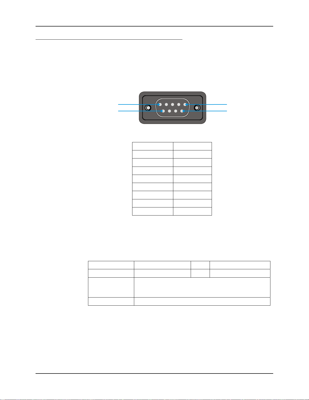
External Connectors 39
6
Technical Specifications – Connection Cable
The exact serial cable is crucial. Many commercial null modem cables will not work. LXE
recommends the following cable:
Serial cable:
9000A054CBL6D9D9
5
1
9
Pinout:
DB9 female DB9 female
1 7
2 3
3 2
4 6, 8
5 5
6, 8 4
7 1
9 no connection
Figure 2-5 Pinout – Serial Cable
Some laptop devices do not properly implement all control lines on the serial port – the laptop
connection will not work.
RTS/CTS Handshaking and the Serial Port
RTS Ready to Send CTS Clear to Send
DTR Data Terminal Ready DSR Data Set Ready
Remote Side The device sending data to and receiving data from the VX6
through the LXE serial cable connected to the RS-232 ports on
both devices.
LXE Serial Cable 9000A054CBLD9D9
The VX6 serial port supports four types of handshaking via the LXE serial cable: None, standard
Xon/Xoff, standard DTR/DSR, and a form of RTS/CTS.
To use RTS/CTS, the remote side computer must clear the DTR line which sets the VX6 CTS line
and allows the VX6 to send data to the remote side.
This allows signals and data to travel smoothly between both devices.
E-EQ-VX6RG-J VX6 Reference Guide
Page 62
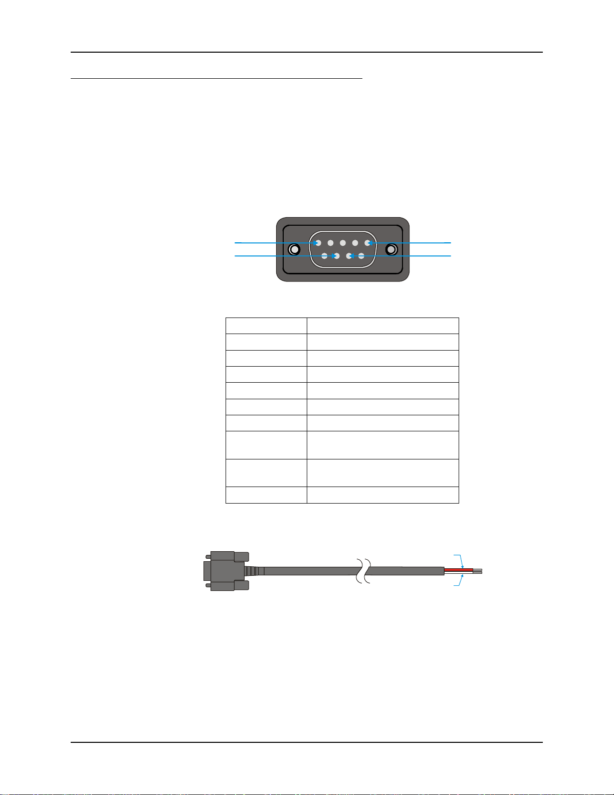
40 External Connectors
7
Technical Specifications – Screen Blanking Cable
The customer must supply their own cable. The cable must be designed so that pin 7 (RTS –
Request to Send Output) and pin 8 (Clear to Send Input) of a D9 female connector provide
continuity only when the vehicle is stopped (for example, via a switch on the accelerator pedal of
the fork truck). All other pins on the connector must be left unconnected. If pins 7 and 8 do not
provide continuity (or the cable is removed), the VX6 screen remains blank.
Serial cable:
Customer built cable with the following specifications:
Pinout:
5
8
DB9 female Function
1 Not Used
2 Not Used
3 Not Used
4 Not Used
5 Not Used
6 Not Used
7 No signal when in motion,
Continuity to Pin 8 when stopped
8 No signal when in motion,
Continuity to Pin 7 when stopped
9 Not Used
Figure 2-6 Pinout – Screen Blanking Cable
1
Pin 8
Pin 7
Figure 2-7 Sample Cable for Screen Blanking
Please refer to Chapter 4, “Scanner”, for the proper COM port settings to support screen blanking.
VX6 Reference Guide E-EQ-VX6RG-J
Page 63
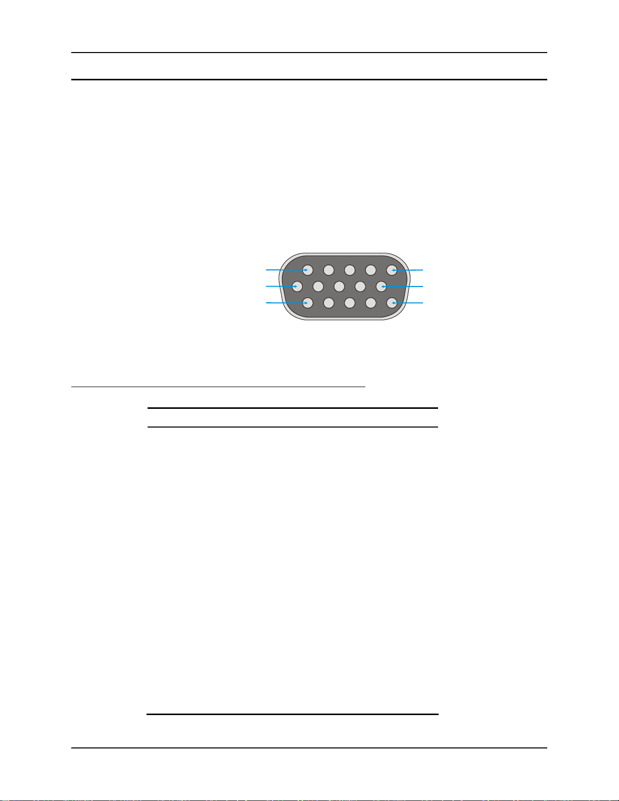
External Connectors 41
5
Ethernet/USB Connector
The VX6 Ethernet/USB connector accepts dongle cables that provide combinations of the
following connections:
• an Ethernet port, via an RJ45 connector
• a USB Host port for connecting a USB device to the VX6
• a USB Client port to connect the VX6 to a USB host or hub.
Note: Please refer to the diagrams later in this chapter for details on available ports with the
dongle cable options.
The connector is shown below.
15
6
11 1
10
Pinout
Figure 2-8 VX6 USB Connector and External USB Adapter Cable Connector
Note: Power the VX6 off before attaching a cable or device to the Ethernet/USB connector.
Pin Signal Description
1 USB2N_A USB D –
2 – Not Connected
3 – Not Connected
4 RXP Receive +
5 RXN Receive –
6 USB2P_A USB D +
7 DGND USB Power Return
8 – Not Connected
9 RJ45_45 RJ45, Pins 4 and 5 Connections
10 RJ45_78 RJ45, Pins 7 and 8 Connections
11 5V_USB_23 USB Power, Current Limited
12 – Not Connected
13 – Not Connected
14 TXN Transmit –
15 TXP Transmit +
Shell CGND Chassis Ground
E-EQ-VX6RG-J VX6 Reference Guide
Page 64
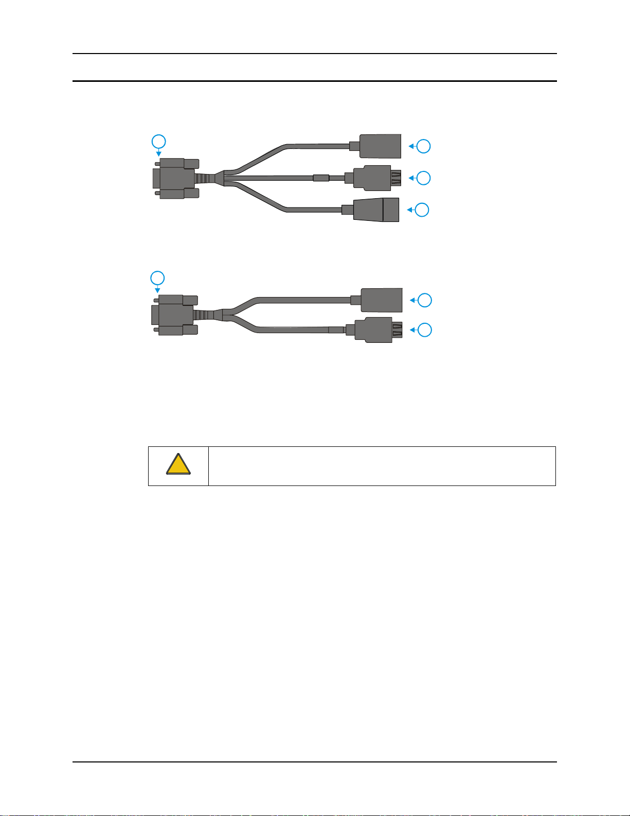
42 External Connectors
Ethernet/USB Dongle Cables
The available dongle cables are shown below.
1
9000A075CBLUSBHCETH
1
9000A071CBLD15USBETH
Figure 2-9 VX6 Ethernet/USB Dongle Cables
Note: Power the VX6 off before attaching a cable or device to the Ethernet/USB connector.
The connectors and pinouts for the dongle cables are detailed below.
1 D15 Connector
2
2 RJ45 Connector
3
3 USB Host
4
2
3
Connector
4 USB Client
Connector
1 D15 Connector
2 RJ45 Connector
3 USB Host
Connector
!
9000A075CBLUSBHCETH is required when using ActiveSync via USB on the
VX6.
VX6 Reference Guide E-EQ-VX6RG-J
Page 65
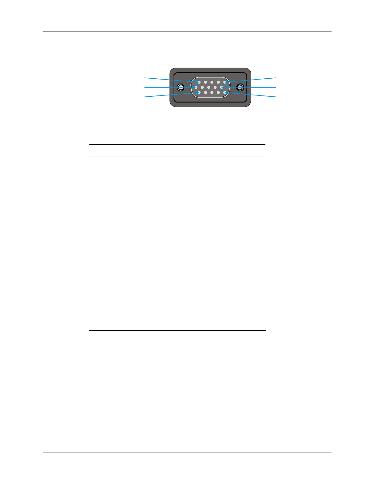
External Connectors 43
D15 Female Connector
Pinout
5
10
15
Figure 2-10 D15 Female Connector
Pin Signal Description
1 USB2N_A USB-H D –
2 – Not Connected
3 USB-D Power
4 RXP Receive +
5 RXN Receive –
6 USB2P_A USB-H D +
7 DGND USB-H Power Return
8 USB-D D –
9 RJ45_45 RJ45, Pins 4 and 5 Connections
1
6
11
10 RJ45_78 RJ45, Pins 7 and 8 Connections
11 5V_USB_23 USB-H Power, Current Limited
12 USB-D Power Return
13 USB-D D +
14 TXN Transmit –
15 TXP Transmit +
Shell CGND Chassis Ground
E-EQ-VX6RG-J VX6 Reference Guide
Page 66
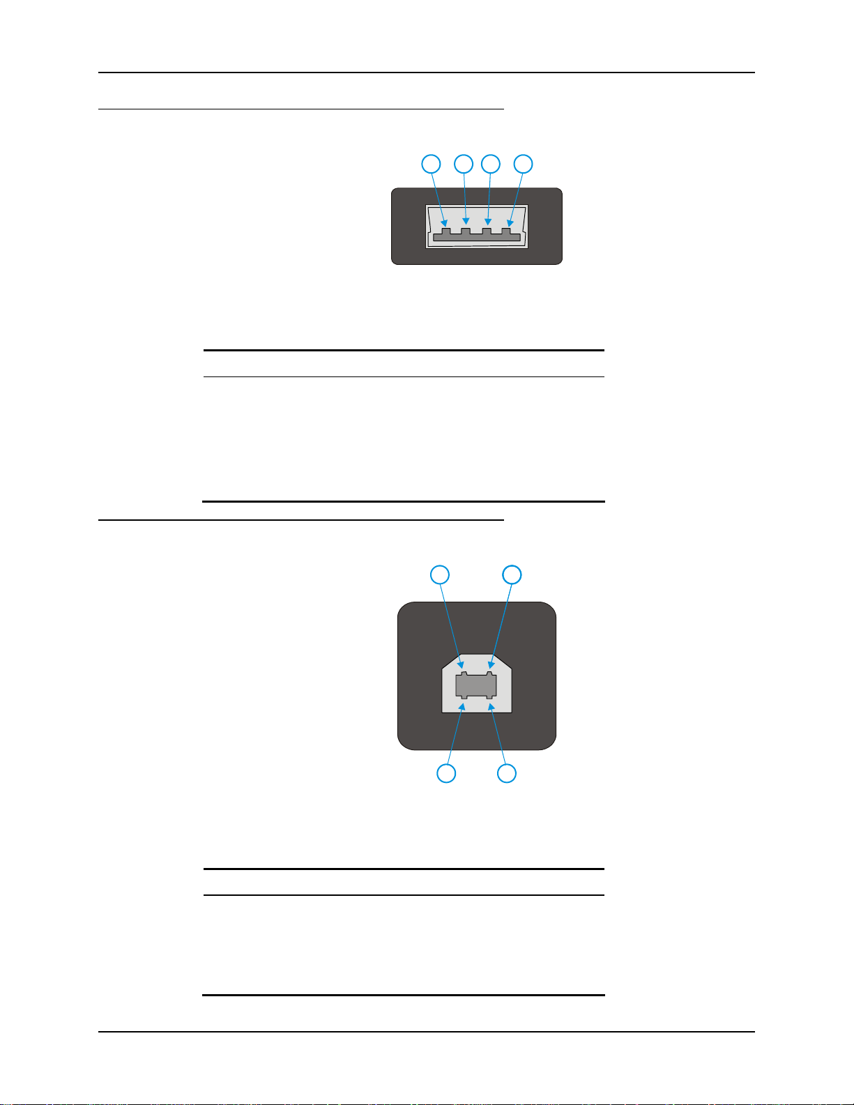
44 External Connectors
USB Host Connector
124 3
Figure 2-11 Dongle Cable USB Host Port
Pinout
Pin Signal Description
1 5V_USB_23 USB Power, Current Limited
2 USB2N_A USB D –
3 USB2P_A USB D +
4 DGND USB Power Return
Shell CGND Chassis Ground
USB Client Connector
Pinout
Pin Signal Description
12
1
3 4
Figure 2-12 Dongle Cable USB Client Port
1 5V_USB_23 USB Power, Current Limited
2 USB2N_A USB D –
3 USB2P_A USB D +
4 DGND USB Power Return
VX6 Reference Guide E-EQ-VX6RG-J
Page 67
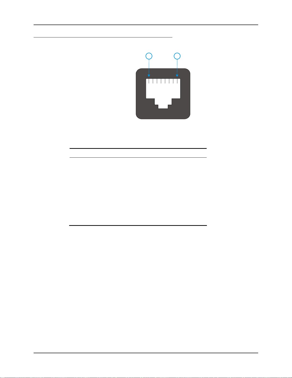
External Connectors 45
RJ45 Connector
1 8
Figure 2-13 Dongle Cable Ethernet Port
Pinout
Pin Signal Description
1 TXP Transmit +
2 TXN Transmit –
3 RXP Receive +
4 – Not Connected
5 – Not Connected
6 RXN Receive –
7 – Not Connected
8 – Not Connected
E-EQ-VX6RG-J VX6 Reference Guide
Page 68
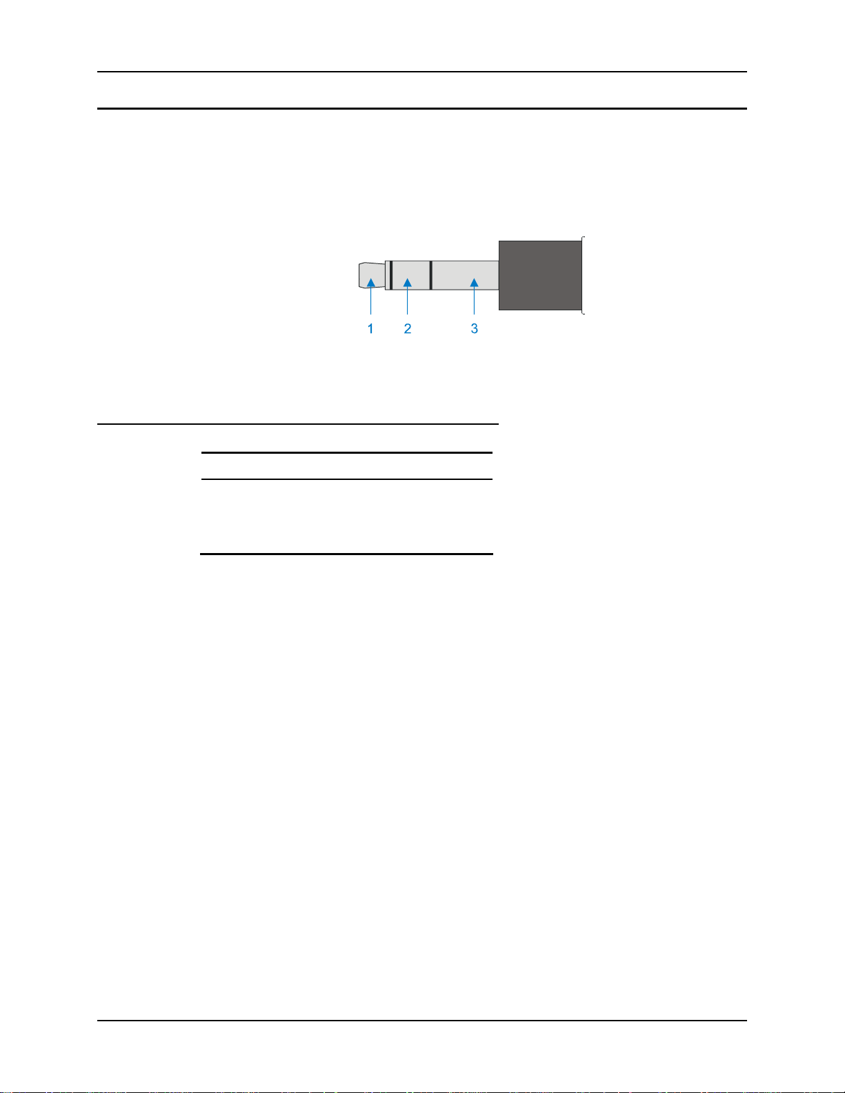
46 External Connectors
Audio Connector
The VX6 audio connector accepts a headset with a 2.5mm plug, such as a mono telephone headset
with microphone or a stereo headset.
Please refer to “Mixer” in Chapter 3, “System Configuration” for information on configuring the
audio port for either a mono headset with microphone or a stereo headset.
Figure 2-14 VX6 Audio Jack for External Speaker or Headphones
Note: The VX6 is not configured for standard PC speakers.
Pinout
Pin Description
1 Microphone
2 Speaker
3 Ground
VX6 Reference Guide E-EQ-VX6RG-J
Page 69

External Connectors 47
3
5
Power Supply Connector
Power is supplied to the VX6 through the power connector. Additionally this assembly provides a
connection point for the vehicle’s chassis ground to be connected internally to the conductive
chassis of the computer.
The VX6 internal power supply can accept DC input voltages in the range of 12 to 80 Volts.
1
2
4
Figure 2-15 The Power Connector
Pinout
Pin Signal
1 DC Positive (+)
2 UPS Battery Positive (+)
3 Chassis Ground
4 UPS Battery Negative (–)
5 DC Negative (–)
E-EQ-VX6RG-J VX6 Reference Guide
Page 70
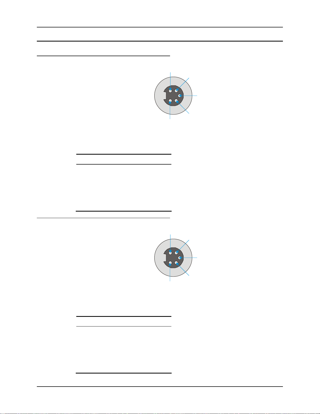
48 External Connectors
3
5
3
5
UPS Battery Pack Connectors
Input
1
2
4
Figure 2-16 The UPS Battery Pack Input Connector
Pinout
Pin Signal
1 DC Positive (+)
Output
Pinout
2 Not used
3 Chassis Ground
4 Not used
5 DC Negative (–)
1
2
4
Figure 2-17 The UPS Battery Pack Output Connector
Pin Signal
1 DC Positive (+)
2 UPS Battery Positive (+)
3 Chassis Ground
4 UPS Battery Negative (–)
5 DC Negative (–)
VX6 Reference Guide E-EQ-VX6RG-J
Page 71
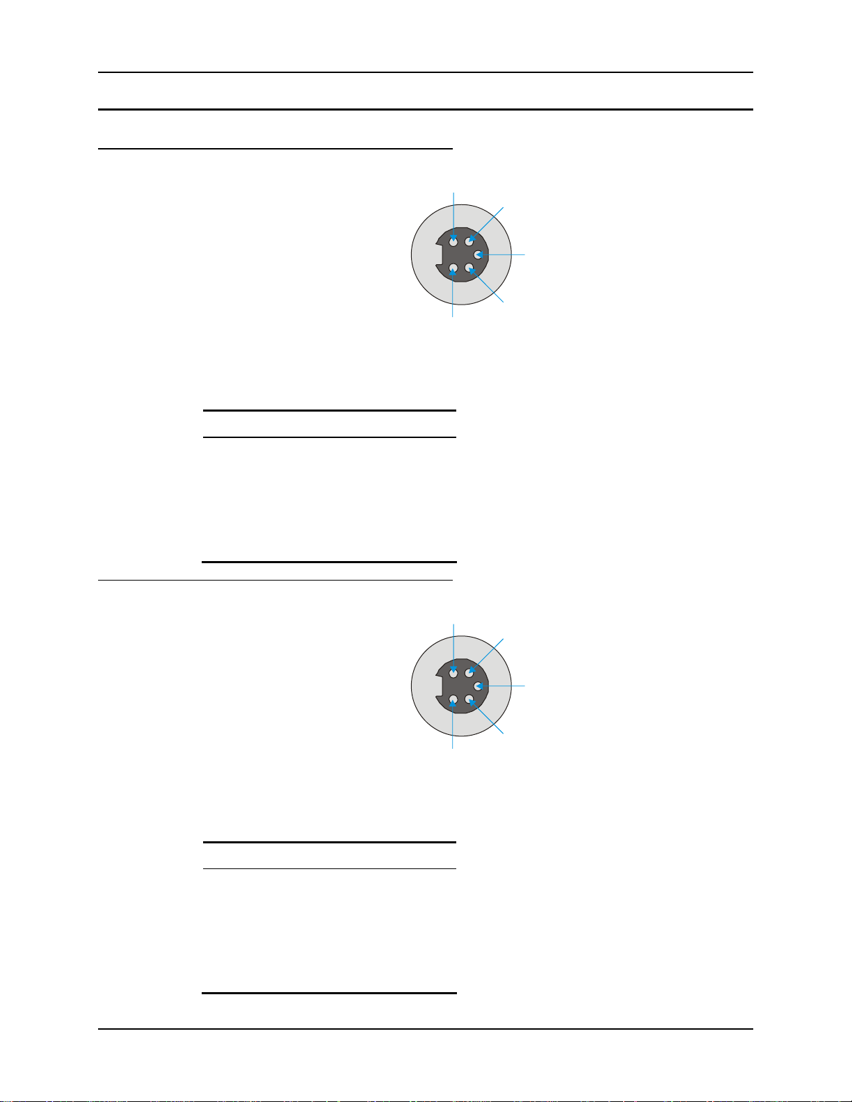
External Connectors 49
3
5
3
5
UPS Battery Extension Cable Connectors
Input
1
2
4
Figure 2-18 The UPS Battery Extension Cable Input Connector
Pinout
Pin Signal
1 DC Positive (+)
Output
Pinout
2 UPS Battery Positive (+)
3 Chassis Ground
4 UPS Battery Negative (–)
5 DC Negative (–)
1
2
4
Figure 2-19 The UPS Battery Extension Cable Output Connector
Pin Signal
1 DC Positive (+)
2 UPS Battery Positive (+)
3 Chassis Ground
4 UPS Battery Negative (–)
5 DC Negative (–)
E-EQ-VX6RG-J VX6 Reference Guide
Page 72
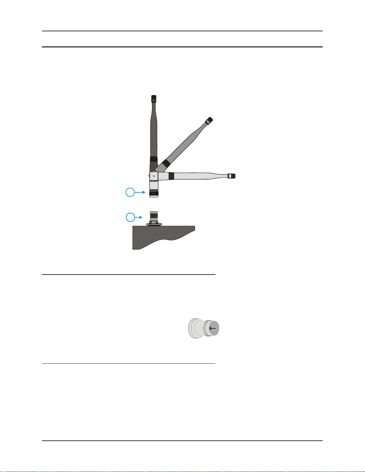
50 External Connectors
Antenna Connections
Note: VX6’s are equipped with a radio and require an either an external or an internal
antenna. Some VX6’s may be equipped with a dual antenna option. For these VX6’s, an
external antenna must be connected to each antenna connector.
1. Antenna
2. Antenna Connector
1
2
Figure 2-20 External Antenna
Spread Spectrum RF Antenna Connector Pin
VX6’s ordered with an external antenna option have either one or two antenna connectors located
on top of the unit. VX6’s ordered with the internal antenna option do not have an external
antenna connector.
Figure 2-21 RF Antenna SS Connector
Vehicle Remote Antenna Mount
The external antenna (or antennas) can be remotely mounted on the vehicle. Please refer to the
“Vehicle Remote Mount Antenna Installation Sheet” for details.
VX6 Reference Guide E-EQ-VX6RG-J
Page 73
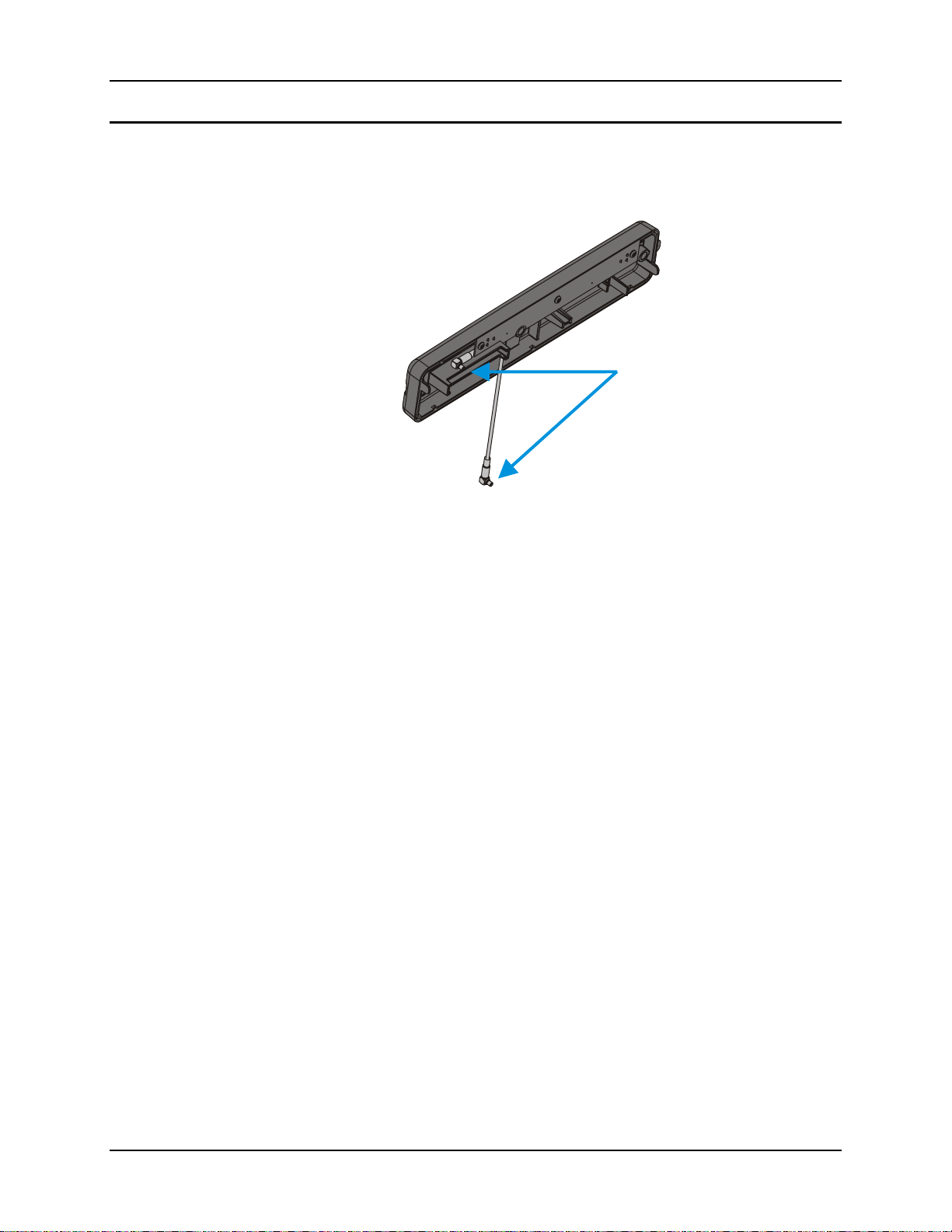
External Connectors 51
Internal Antenna
If the internal antenna option is ordered, an antenna is mounted on the inside of the user access
panel cover.
Figure 2-22 Internal Antenna Cables
The internal antenna assembly has two antenna cables which are attached to the radio card.
E-EQ-VX6RG-J VX6 Reference Guide
Page 74
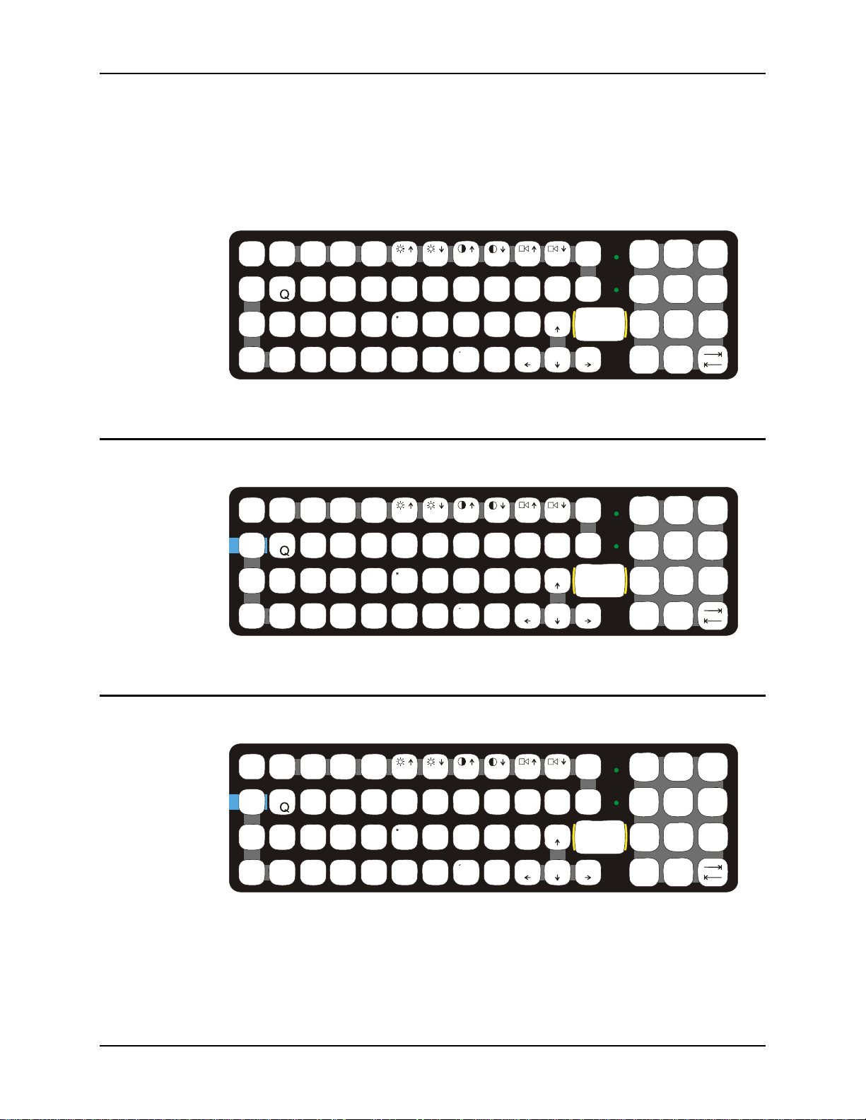
52 The QWERTY Keyboard
The QWERTY Keyboard
The VX6 has a QWERTY keyboard, available with a standard overlay, an IBM 3270 overlay or
an IBM 5250 overlay. These keyboards have 101 keyboard functions, including a numeric
keypad. Please refer to Appendix A, “Key Maps”, for keypress combinations.
IBM 3270 Overlay
CAPS
ESC
2ND
!
CTRL
|\
SHIFT
ADFGH
ALT SP
BREAK
F1 F2
@
#
EIO
WY
S
Figure 2-23 QWERTY Keyboard Standard
PA1 PA2
CAPS
ESC
2ND
!
CTRL
Attn
|\
SHIFT
ADFGH
ALT SP
BREAK
F1 F2
@
#
EIOPRT
WY
Del
SysReq
S
R/S
F3
F4
$%
RT
:;
C
VXZ
PA3
R/S
F3
F4
Rst
$
%
:;
Clr
C
VXZ
F5 F6
^
F7
&
*
U
,.
‘
J
KL
~
B
F5 F6
^&*
_
MN
F7
Ins E-Inp
U
,.
‘
J
KL
NL
~
B
_
MN
F8 F9
()
P
PgUp
?
PgDn
Home
F8 F9
()
PgUp
?
PgDn
Home
BKLT
F10
INS
BKSP
ENTER
END
BKLT
F10
INS
BKSP
ENTER
END
CAPS
/
2nd
=
[]
<
CAPS
/
2nd
=
[]
<
8
7
{
5
4
12
DEL
0
.
8
7
{
5
4
12
DEL
0
.
+
9
}
6
>
3
+
9
}
6
>
3
Figure 2-24 QWERTY Keyboard with IBM 3270 Overlay
IBM 5252 Overlay
ESC
CTRL
SHIFT
ALT SP
CAPS
2ND
F1 F2
@
!
WY
Attn
SysReq
|\
S
ADFGH
R/S
BREAK
F3
#
EIOPRT
Del
F4
$
%
:;
Clr
C
VXZ
F5 F6
^&*
F7
DupNLIns
U
,.
‘
J
KL
Fld-
~
B
_
MN
F8 F9
()
Fld+
PgUp
?
PgDn
Home
BKLT
F10
E-Inp
INS
BKSP
Field Exit
ENTER
END
CAPS
2nd
Figure 2-25 QWERTY Keyboard with IBM 5250 Overlay
Note: Press the <CTRL> + <Enter> keys to initiate the IBM 5250 Field Exit Function.
VX6 Reference Guide E-EQ-VX6RG-J
-
/
=
[]
<
8
7
{
5
4
12
DEL
0
.
+
9
}
6
>
3
Page 75

The QWERTY Keyboard 53
Key Maps
The keyboard supports all 101 keyboard functions. However, because the keyboard only has 60
keys, all functions are not visible (or printed on the keyboard). Therefore the VX6 keyboard
supports what is called hidden keys -- keys that are accessible but not visible on the keyboard.
The hidden keys supported by the VX6 are listed in Appendix A, “Key Maps”.
Custom Key Maps
A key or combination of keys can be remapped to provide a single keypress, a string of
keypresses or to execute an application or command.
All key remapping is done using the KeyPad option in the Control Panel. Please see KeyPad in
Chapter 3, System Configuration, for details.
NumLock and the VX6
The keyboard does not have a NumLock indicator or key. NumLock is always On.
Keyboard Backlight
The LXE keyboard keys are backlit. The keyboard backlight and the display share the same
timer, which is configured in the Windows CE Control Panel. When the display is On, the
keyboard backlight is also On. Please refer to “Power Management” later in this document for
information on configuring the timeout.
E-EQ-VX6RG-J VX6 Reference Guide
Page 76
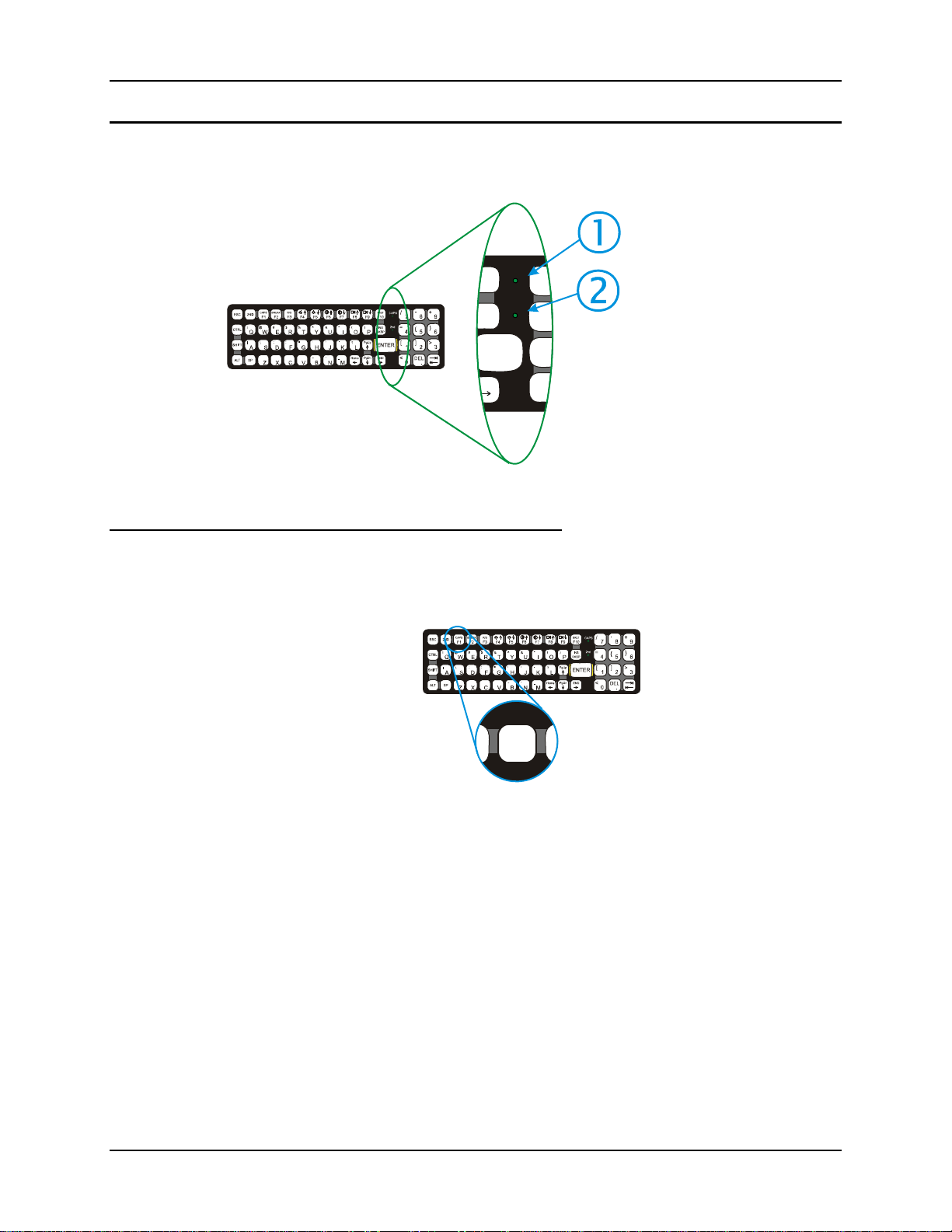
54 The QWERTY Keyboard
Keyboard LEDs
The VX6 keyboard has two (2) LED indicators.
CAPS
KLT
F10
INS
BKSP
ENTER
END
Figure 2-26 Keyboard LEDs
2nd
/
7
=
4
[
1
<
0
1. CapsLock Mode LED
Indicator
2. Secondary Mode LED
Indicator
CAPS LED
This LED indicates the state of the keyboard CapsLock mode. If CapsLock is enabled this LED is
illuminated green. When CapsLock is off, the LED is dark.
B
CAPS
D
F1
Figure 2-27 The CapsLock Key
Press <2
nd
> then <F1> to toggle CapsLock On and Off.
The default value of CapsLock is “Off”.
For information on preserving CapsLock configuration after a reboot, please see “Configuring
CapsLock Behavior” in Chapter 3, “System Configuration”.
VX6 Reference Guide E-EQ-VX6RG-J
Page 77
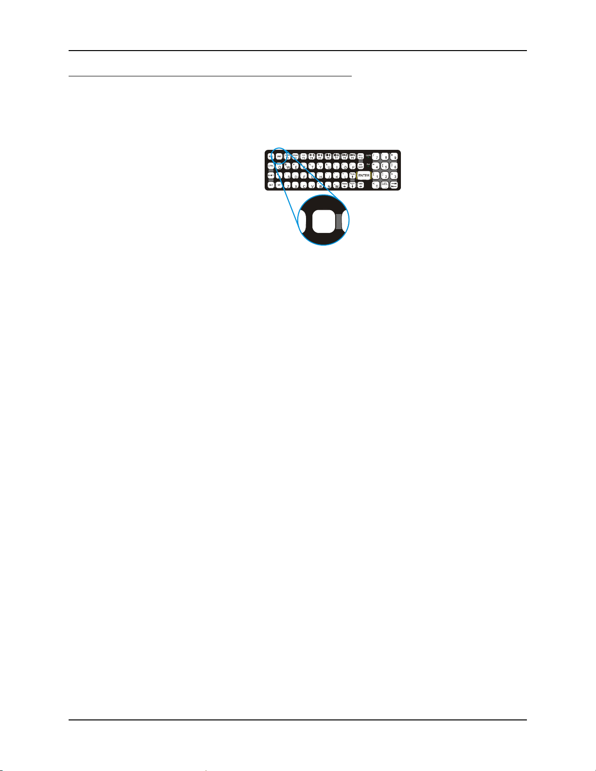
The QWERTY Keyboard 55
Secondary Keys LED
The VX6 keyboard is equipped with several secondary keys. These keys are identified by the
superscripted text found on the keyboard keys. The secondary keys are accessible by using two
(2) keystrokes: the <2
nd
> key followed by the superscripted key.
nd
Once the <2
illuminated and the <2
with a <2
> state is enabled (by pressing the <2nd> key) the Secondary Mode LED is
nd
> keypress and then immediately off with another <2nd> keypress.
For example:
nd
Press <2
Press <2
Press <2
Press <2
> and <F1> to turn CapsLock on and off.
nd
> and <↑> to initiate the PgUp command.
nd
> and <Q> to type the “!” key.
nd
> and <BkSp> to enter the Insert (Ins) mode.
2ND
C
C
Figure 2-28 The Secondary Key
nd
> state is enabled until another key is pressed. The <2nd> key is toggled on
E-EQ-VX6RG-J VX6 Reference Guide
Page 78
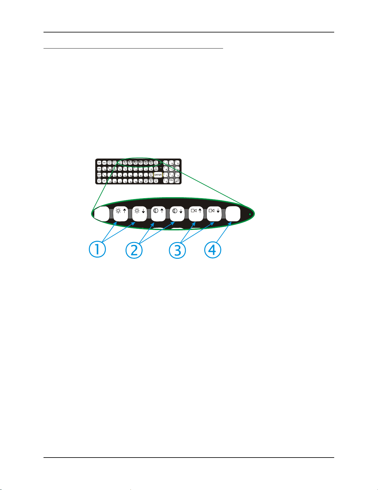
56 The QWERTY Keyboard
Control Keys
The VX6 keyboard has several control keys, some of which are not used on the VX6.
Note: The 2
adjusted via the buttons on the control panel.
The 2
screen with no provision for contrast adjustments.
The 2
VX6 is controlled with the Volume and Sounds icon in the Microsoft Windows CE
Control Panel.
The 2
the keyboard backlight.
R/S
F3
F4 F5
nd
functions of the <F4> and <F5>keys are not used as the display brightness is
nd
functions of the <F6>, and <F7> keys are not used as the VX6 has TFT LCD
nd
functions of the <F8> and <F9> keys are not used as the sound volume on the
nd
function of the <F10> key is not used as the display backlight timer also controls
1. Display Brightness
Control Keys (Not
used)
2. Display Contrast
Control Keys (Not
used)
3. Speaker Volume
F6
F7
F8
F9
BKLT
F10
Control Keys (Not
used)
4. Backlight Control
Key (See above)
Figure 2-29 The VMT Keyboard Display Controls
VX6 Reference Guide E-EQ-VX6RG-J
Page 79

The QWERTY Keyboard 57
General Windows CE Keyboard Shortcuts
Use the keyboard shortcuts in the chart below to navigate with the VX6 keyboard. These are
standard keyboard shortcuts for Windows CE applications.
Press these keys … To …
CTRL + C Copy
CTRL + X Cut
CTRL + V Paste
CTRL + Z Undo
DELETE Delete
SHIFT with any of the arrow keys
CTRL+A Select all.
ALT+ESC Cycle through items in the order they were opened.
CTRL+ESC Display the Start menu.
ALT+Underlined letter in a menu
name
Underlined letter in a command
name on an open menu
ESC Cancel the current task.
The touchscreen provides equivalent functionality to a mouse:
• A touch on the touchscreen is equivalent to a left mouse click.
• Many items can be moved by the “drag and drop” method, touching the desired item,
moving the stylus across the screen and releasing the stylus in the desired location.
• A double stylus tap is equivalent to a double click.
• A touch and hold is equivalent to a right mouse click.
Note: Some applications may not support this right click method. Please review
documentation for the ap plication to see if it provides fo r right mouse click
configuration.
Select more than one item in a window or on the
desktop, or select text within a document.
Display the corresponding menu.
Carry out the corresponding command.
USB Keyboard/Mouse
A standard USB mouse can be attached to the VX6 using the appropriate dongle cable. A standard
USB keyboard can be attached to Platform 2 VX6’s using the appropriate dongle cable. The
dongle cable attaches to the VX6 and provides a USB connector. Please refer to documentation
provided with the USB keyboard and mouse for more information on their operation.
To identify your VX6 platform type, please see “Identifying Your VX6”, earlier in
P
E-EQ-VX6RG-J VX6 Reference Guide
this chapter.
Page 80
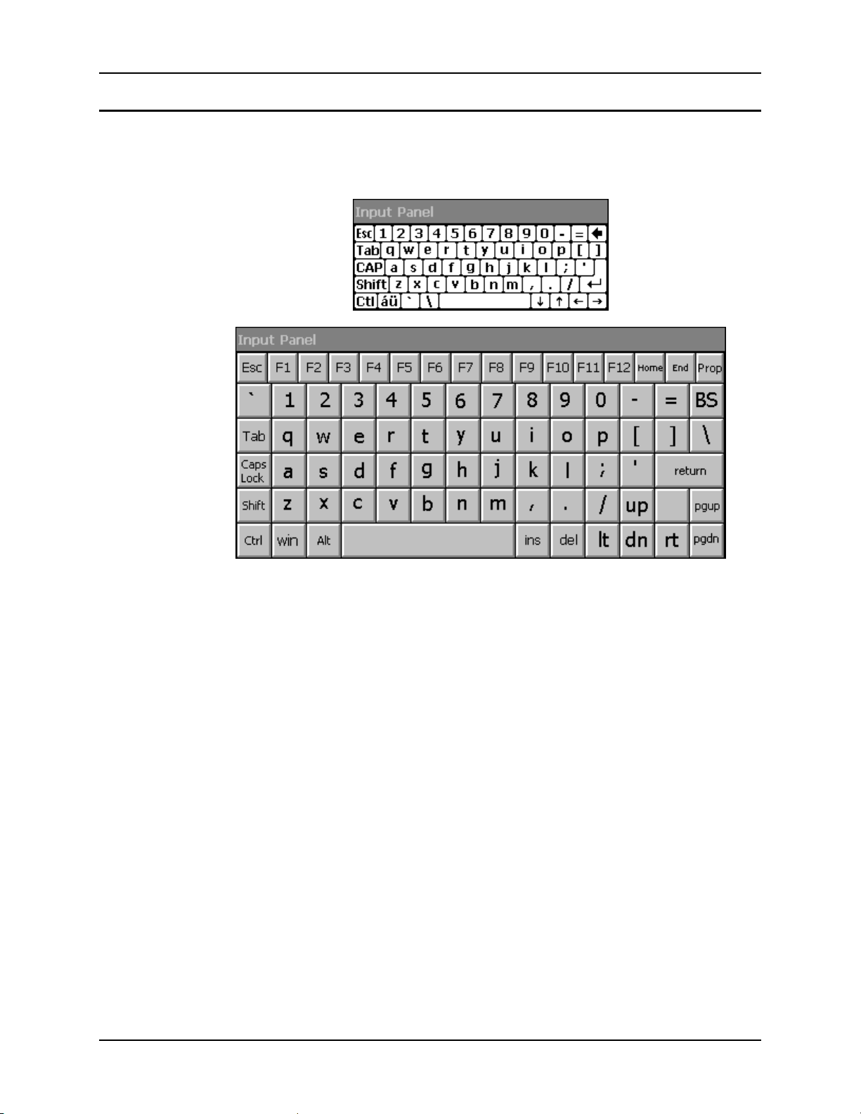
58 The QWERTY Keyboard
Input Panel (Virtual Keyboard)
The Input Panel may be enabled via the Input Panel icon in the Control panel. The Input Panel
can be displayed as a large or small keyboard.
Figure 2-30 Small and Large Virtual Keyboards
Virtual keyboards display the actual character a keypress results in. For example, pressing the
<Shift> key on the virtual keyboard toggles the characters displayed on the keys between upper
and lower case. The <áü> key toggles the keys between standard and international symbols. The
<Shift> and <áü> keys can be used in combination for capitalized international characters.
Note: When the virtual keyboard is displayed, the physical keyboard is still active. Therefore it
is possible to input data from both keyboards.
VX6 Reference Guide E-EQ-VX6RG-J
Page 81
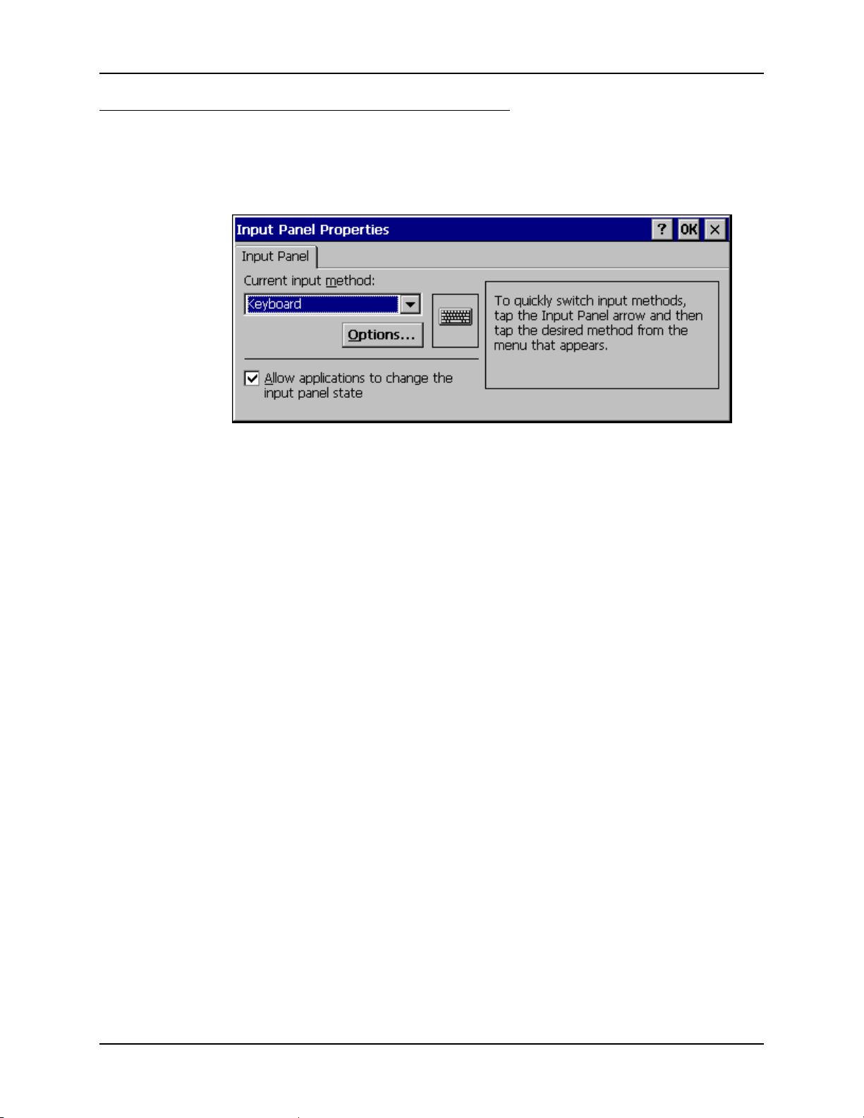
The QWERTY Keyboard 59
Enabling the Input Panel
The Input Panel is disabled by default. To enable the Input Panel, select Start | Settings |
Control Panel | Input Panel icon. Make sure the “Allow applications to change the input panel
state” checkbox is checked and warmboot the VX6.
Figure 2-31 Input Panel Properties
E-EQ-VX6RG-J VX6 Reference Guide
Page 82

60 The Display
The Display
The VX6 Display is a thin-film transistor display capable of supporting half screen SVGA+
graphics modes. Display size is 800 x 320 pixels. The display covering is designed to resist stains.
The touchscreen allows signature capture and touch input.
The display supports screen blanking to eliminate driver distraction when the vehicle is in motion.
Please see “Technical Specifications – Screen Blanking Cable” earlier in this chapter and “Screen
Blanking” in Chapter 3, System Configuration” for details.
Cleaning the Display
Touchscreen
Keep fingers and rough or sharp objects away from the display. If the glass becomes soiled or
smudged, clean only with a standard household cleaner such as Windex
Isopropyl Alcohol. Do not use paper towels or harsh-chemical-based cleaning fluids since they
may result in damage to the glass surface. Use a clean, damp, lint-free cloth. Do not scrub optical
surfaces. If possible, clean only those areas which are soiled. Lint/particulates can be removed
with clean, filtered canned air.
The touchscreen is a Resistive Panel with a scratch resistant finish that can detect touches by a
stylus, and translate them into computer commands. In effect, it simulates a computer mouse.
Only Delrin or plastic styluses should be used. A right mouse click is simulated by touching and
holding the screen for the appropriate time interval.
Note: Always use the point of the stylus for tapping or making strokes on the display. Never use
an actual pen, pencil or sharp object to write on the touchscreen.
An extra or replacement stylus may be ordered from LXE. See the “Accessories” section for the
stylus part number.
Please refer to Chapter 3, “System Configuration” for more information on:
• Calibrating the touchscreen
• Disabling the touchscreen.
LXE offers a replaceable touchscreen protective film to protect the touchscreen when the VX6 is
used in an abrasive environment. For information on installing or removing the protective film,
please refer to the “VX6 User’s Guide”.
®
without vinegar or use
Touchscreen Heater
Extended temperature versions of the VX6 contain a touchscreen heater. The touchscreen heater
can be disabled on Platform 2 VX6’s when not needed. Please see “MX3-VXC Options” in
Chapter 3, “System Configuration”.
To identify your VX6 platform type, please see “Identifying Your VX6”, earlier in
P
this chapter.
VX6 Reference Guide E-EQ-VX6RG-J
Page 83
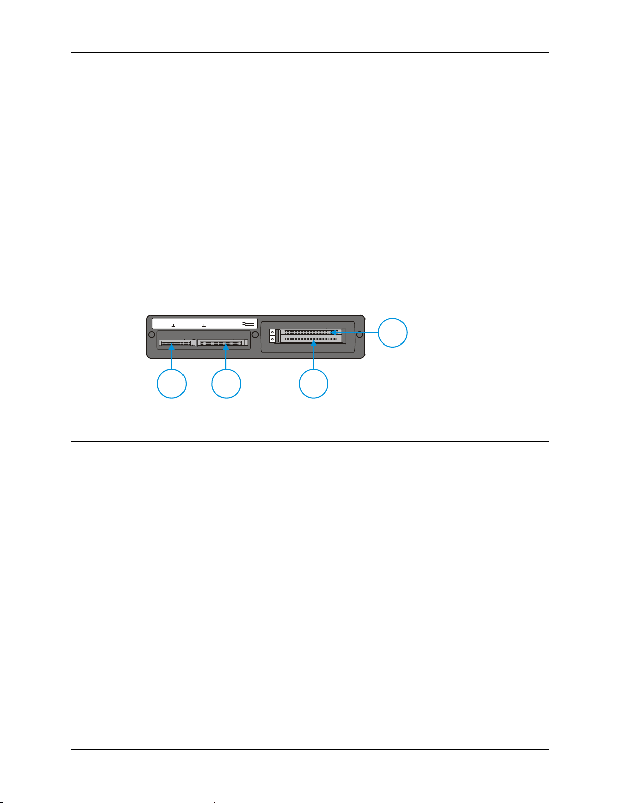
PCMCIA, CF and SD Slots 61
PCMCIA, CF and SD Slots
The VX6 has two PCMCIA slots, one Compact Flash slot and one Secure Digital slot. The
PCMCIA slots are stacked on top of each other and located on the right hand side of the opening.
The PCMCIA slots support the Personal Computer Memory Card International Association
(PCMCIA) 2.1 standards. The upper slot is designated as Slot A and the lower slot is designated
as Slot B.
Slot A accepts Type I or II PCMCIA cards. If a radio card is used, it must be installed in Slot A to
prevent damage to the internal radio cables. LXE supports only Type II radios.
Slot B accepts Type I or II PCMCIA cards.
The PCMCIA slots may be disabled by the user. To enable or disable a PCMCIA slot, select
Start | Settings | Control Panel | PCMCIA icon.
The center slot is a Compact Flash slot, containing the CF ATA hard drive. This drive contains
the operating system and settings.
The left slot is used for Secure Digital (SD) memory cards.
PCMCIA Slots
Slot A and B PCMCIA Card Management is handled by the Microsoft Windows CE operating
system. The PCMCIA cards are Plug and Play devices and can be “hot swapped”. For more
details, refer to the Windows CE help screens or refer to the documentation delivered with the
PCMCIA card.
Note: Although cards in the PCMCIA slot may be hot swapped, the VX6 is not environmentally
SD CF ATA
sealed while the access panel cover is removed to hot swap PCMCIA cards.
PCMCIA A
PCMCIA B
21
Figure 2-32 The PCMCIA and ATA Slots
3
1. SD Card Slot
4
2. Compact Flash Hard
Drive
3. PCMCIA Slots
E-EQ-VX6RG-J VX6 Reference Guide
Page 84

62 PCMCIA, CF and SD Slots
PCMCIA Pinout
Pin Signal Pin Signal
1 GND 35 12V_RF_POWER
2 D3 36 -CDI
3 D4 37 D11
4 D5 38 D12
5 D6 39 D13
6 D7 40 D14
7 -CE1 41 D15
8 A10 42 -CE2
9 -OE 43 n.c. or VS1#
10 A11 44 -IORD
11 A9 45 -IOWR
12 A8 46 A17
13 A13 47 A18
14 A14 48 A19
15 -WE 49 A20
16 RDY/-IREQ 50 A21
17 SLOT_VCC 51 SLOT_VCC
18 SLOT-VPP 52 SLOT_VPP
19 A16 53 A22
20 A15 54 A23
21 A12 55 A24
22 A7 56 A25
23 A6 57 n.c. or VS2#
24 A5 58 RESET
25 A4 59 -WAIT
26 A3 60 -INPACK
27 A2 61 -REG
28 A1 62 BVD2/-SPKR
29 A0 63 BDV1/-STSCHG
30 D0 64 D8
31 D1 65 D9
32 D2 66 D10
33 WP/A_-IOIS16 67 -CD2
34 GND 68 GND
VX6 Reference Guide E-EQ-VX6RG-J
Page 85
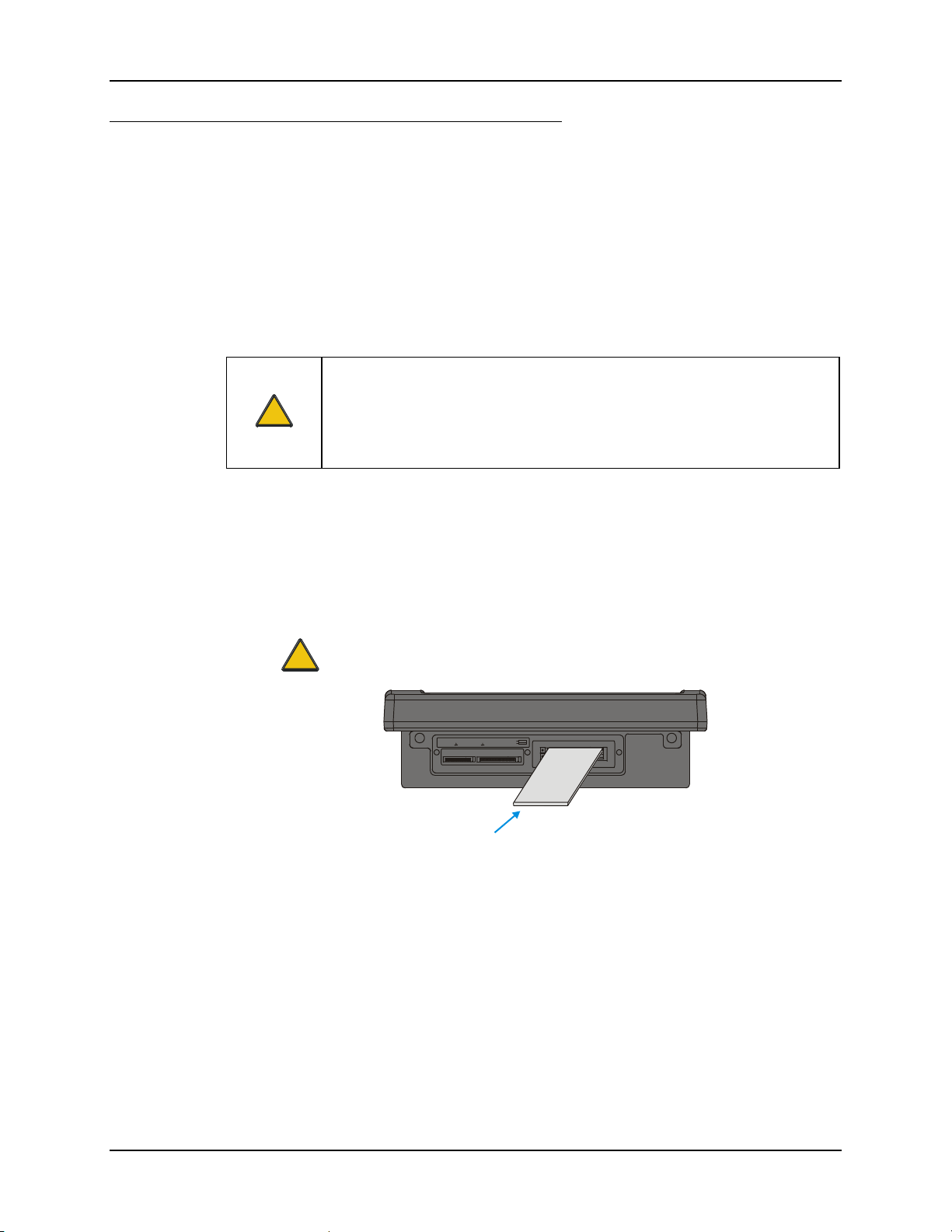
PCMCIA, CF and SD Slots 63
d
Install PCMCIA Cards
Equipment Needed: Phillips No. 1 screwdriver and a Torque wrench capable of measuring to 9±1
inch pounds (1.016±.11 N/m).
Note: The example below details installing a wireless radio card. Installation of other
PCMCIA cards is similar, except there is no antenna.
The radio card is installed in slot A (the upper slot). When a second PCMCIA card is present,
such as a Bluetooth CF card via a PCMCIA adapter, the second card is installed in Slot B (the
lower slot).
Install the Type II PCMCIA Radio
Caution
The LXE Model VX6 Vehicle Mount Computer is specifically for use with LXE
Model 6726, 6816, 4830 and 4831 Type II PCMCIA radios. Substitution of
!
other PCMCIA radios will void the FCC, Industry Canada and other
international radio certifications for the Model VX6 Vehicle Mount Computer
and is strictly prohibited.
1. Turn the VX6 off and detach the power cable.
2. Loosen the three (3) Phillips head screws securing the access panel cover so the cover can
be removed. The screws are a captive part of the cover and cannot be removed.
Partially insert the Type II PCMCIA Radio into Slot A (the upper right slot).
Caution
Slot A MUST BE used for the radio card. Installing a radio card in Slot B can
result in pinching or other damage to the internal antenna cable.
!
SD CF ATA
PCMCIA A
PCMCIA B
Radio Car
Figure 2-33 Inserting the Type II PCMCIA Radio
Note: The tethered access panel cover is not shown in the illustration above.
E-EQ-VX6RG-J VX6 Reference Guide
Page 86
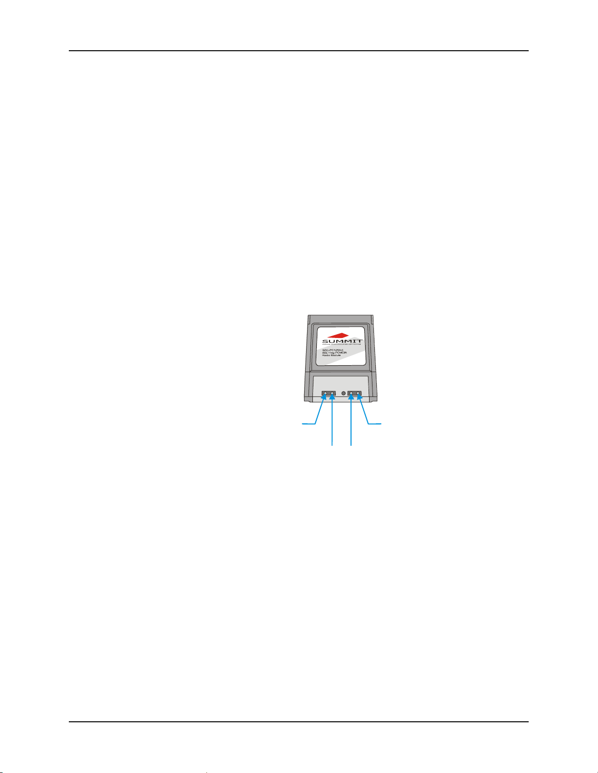
64 PCMCIA, CF and SD Slots
g
A
y
3. Before completely inserting the radio, connect the Antenna Cable(s) to the radio, using the
port(s) indicated below.
Note: Radio cards for single antenna units may have the unused antenna port covered
with tape.
The internal antenna is a dual (diversity) antenna.
Summit CF 802.11a/b/g Radio Card
The Summit 802.11a/b/g radio has four antenna ports, two ports are for the “a” portion
(5.0GHz) of the radio and two ports are for the “b/g” portion (2.4 GHz) of the radio.
CF radio is installed on a PCMCIA adapter. Hold the radio card with the antenna ports
facing down. Connect the antenna cable(s) as follows:
Single antenna – Connect antenna cable to Main a port or the Main b/g port
•
depending on antenna type. Auxiliary port is not used.
Dual a antennas – Connect antenna cables to both Main a and Auxiliary a ports.
•
Dual antennas, one a antenna and one b/g antenna – Connect the a antenna cable
•
to the Main a port and connect the b/g antenna cable to the Main b/g port.
Main
b/g Port
Auxiliary
b/
Port
Figure 2-34 Summit 802.11 a/b/g Antenna Cable Connections
Main
a Port
uxiliar
a Port
VX6 Reference Guide E-EQ-VX6RG-J
Page 87
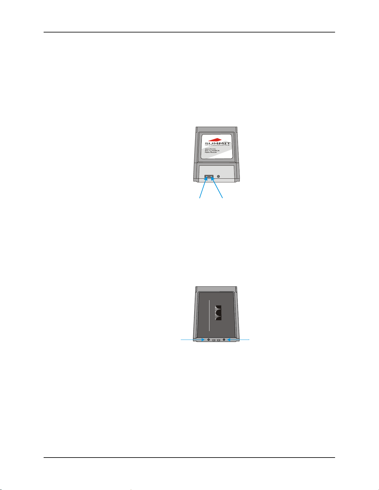
PCMCIA, CF and SD Slots 65
ort
ort
Y
t
Summit CF Radio Card
The Summit 802.11b/g radio has two antenna ports.
The Summit CF radio is installed on a PCMCIA adapter. Hold the radio card with the
antenna ports facing down. Connect the antenna cable(s) as follows:
Summit radio with single antenna – Connect antenna cable to Main port.
•
Auxiliary port is not used.
Summit radio with dual antennas – Connect antenna cables to both Main and
•
Auxiliary ports.
Main
P
Auxiliary
P
Figure 2-35 Summit 802.11b/g Antenna Cable Connections
Cisco Radio Card
Hold the radio card with the Cisco logo label facing up. Connect the antenna cable(s) as
follows:
• Single antenna – Connect antenna cable to right port, as shown below.
• Dual antennas – Connect antenna cables to both ports.
CISCO AIRONET 350
WIRELESS LANADAPTER
C
ISCO
S
STEMS
SERIES
Left Port
Right Por
Figure 2-36 Cisco Antenna Cable Connections
E-EQ-VX6RG-J VX6 Reference Guide
Page 88
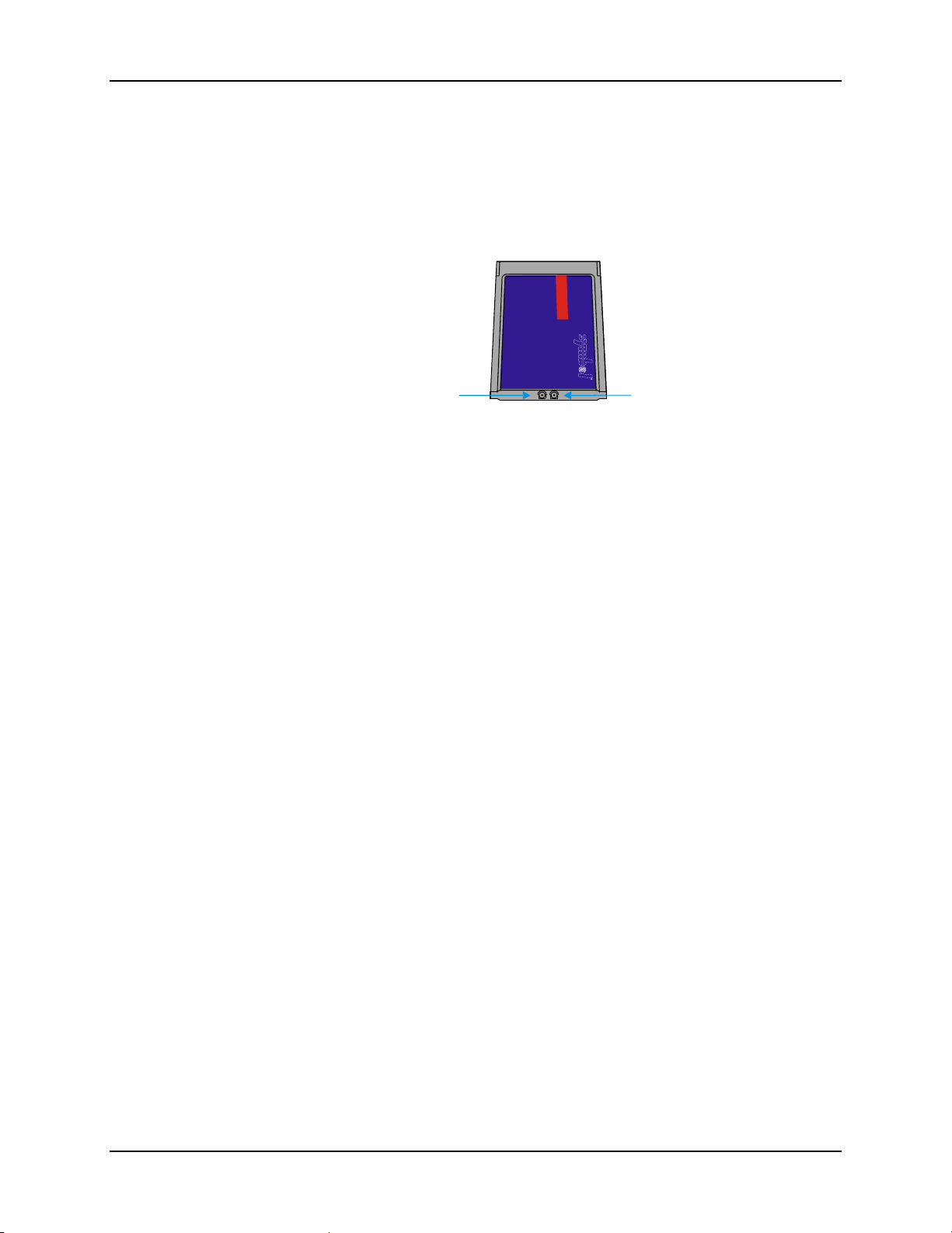
66 PCMCIA, CF and SD Slots
B
Symbol 11Mb Radio Card
Hold the radio card with the Symbol logo label facing up. Connect the antenna cable(s) as
follows:
• Single antenna – Connect antenna cable to Port A (left port), as shown below.
• Dual antennas – Connect antenna cables to both ports.
Spectrum24®
High Rate 11 Mbps
Wireless LANAdapter
IEEE 802.11b
Port A
Port
Figure 2-37 Symbol 11Mb Antenna Cable Connections
4. Now complete the insertion of the Type II PCMCIA Radio into the slot.
No te: When this process is complete, reattach the access cover screws using a torque
wrench capable of measuring to 9±1 inch pounds (1.016±.11 N/m). The screws
must be fastened to 9 inch pounds each. The screws require a Phillips size 1
driver head.
5. Re-connect the power cord/cable and turn the VX6 on.
6. For VX6’s with a Summit radio, review RX Diversity and TX Diversity on the Global
Settings tab of the Summit Client Utility to ensure these settings correspond to the VX6’s
antenna configuration.
VX6 Reference Guide E-EQ-VX6RG-J
Page 89
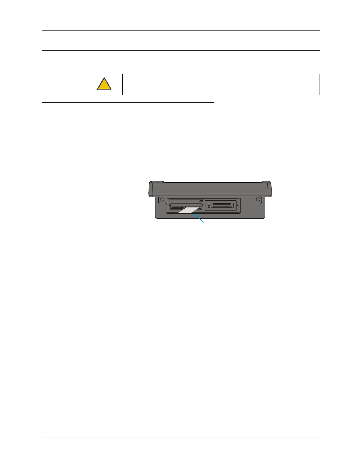
PCMCIA, CF and SD Slots 67
CF Card
CF Card Slot
This slot contains the Compact Flash (CF) hard drive.
Replace a CF Card
1. Turn the VX6 off and detach the power cable.
2. Loosen the three (3) Phillips head screws securing the access panel cover so the cover
3. Remove the card currently installed present in the CF slot and replace it with the new CF
!
The operating system and settings are stored on the CF card. The VX6 cannot
operate without this card. Cards in this slot CANNOT be hot swapped.
can be removed. The screws are a captive part of the cover and cannot be removed.
card. The replacement CF card must contain the operating system in order for the VX6
to operate.
SD CF ATA
PCMCIA A
PCMCIA B
Figure 2-38 Inserting the CF ATA Card
Note: The tethered access panel cover is not shown in the illustration above.
Note: When this process is complete, reattach the access cover screws using a torque
wrench capable of measuring to 9±1 inch pounds (1.016±.11 N/m). The screws
must be fastened to 9 inch pounds each. The screws require a Phillips size 1
driver head.
4. Re-connect the power cord/cable and turn the VX6 on.
E-EQ-VX6RG-J VX6 Reference Guide
Page 90
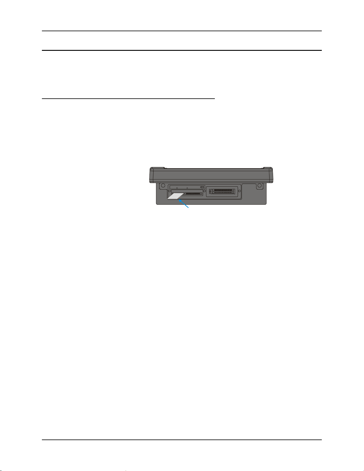
68 PCMCIA, CF and SD Slots
SD Card
SD Card Slot
The slot accepts a Secure Digital (SD) memory card. The card in this slot can be hot swapped.
Note: Although cards in the SD slot may be hot swapped, the VX6 is not environmentally
sealed while the access panel cover is removed to hot swap cards.
Install an SD Card
1. Turn the VX6 off and detach the power cable.
2. Loosen the three (3) Phillips head screws securing the access panel cover so the cover
can be removed. The screws are a captive part of the cover and cannot be removed.
3. Insert the card into the ATA SD. This slot accepts an SD memory card only.
SD CF ATA
PCMCIA A
PCMCIA B
Figure 2-39 Inserting the SD ATA Card
Note: The tethered access panel cover is not shown in the illustration above.
Note: When this process is complete, reattach the access cover screws using a torque
wrench capable of measuring to 9±1 inch pounds (1.016±.11 N/m). The screws
must be fastened to 9 inch pounds each. The screws require a Phillips size 1
driver head.
4. Re-connect the power cord/cable and turn the VX6 on.
VX6 Reference Guide E-EQ-VX6RG-J
Page 91
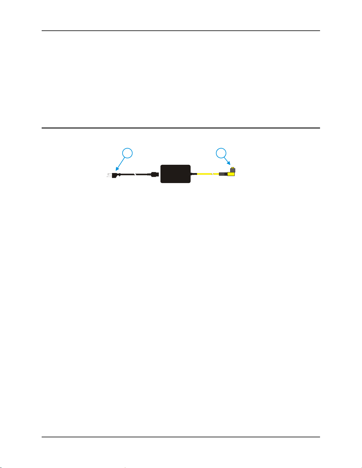
Power Supply 69
Power Supply
AC to DC power input for the VX6 is delivered via an optional external power supply. See
“External Power Supply”.
Vehicle power input for the VX6 is 12V to 80V DC nominal and is accepted without the need to
perform any manual operation within the VX6. See “Vehicle 12-80VDC Direct Connection”. An
optional uninterruptible power supply (UPS) battery can be used with the vehicle DC power
supply.
Power input is fused for protection and the fuse is externally accessible on the VX6.
External Power Supply
21
Figure 2-40 Optional Power Supply Cable
In North America, this unit is intended for use with a UL Listed ITE power supply with
output rated 12 – 80 VDC, minimum 75 W. Outside North America, this unit is intended
for use with an IEC certified ITE power supply with output rated 12 – 80 VDC, minimum
75 W.
The external power supply may be connected to either a 120V, 60Hz supply or, outside North
America, to a 230V, 50Hz supply, using the appropriate detachable cordset. In all cases, connect
the external AC supply to a properly grounded source of supply provided with maximum 15 Amp
overcurrent protection (10 Amp for 230V circuits).
Note: Instructions for using this configuration are contained in “VX6 User’s Guide” section
titled “Installation”.
1. AC Input Cable
(US only)
2. DC Output Cable
E-EQ-VX6RG-J VX6 Reference Guide
Page 92

70 Power Supply
Specifications
Feature Specification
Dimensions 3.40” x 5.87” x 2.00”
Weight <3.0 pounds
Input Power Switch None
Power “ON” Indicator None
Input Fusing None
Input Voltage 90VAC min - 264VAC max
Input Frequency 47 - 63 Hz
Input Surge Current 50 Amps max @ 264VAC input
Input Connector Standard IEC input power cord
(included with US units only)
Output Connector 3 pin female connector
Output Voltage +24VDC
Output Voltage
Tolerance
Output Current 0 Amps min, 1.87 Amps max
Safety and Emissions
Compliance
Environmental Specifications
The AC to DC adapter will withstand the following environmental characteristics:
Feature Specification
Operating Temperature see VX6 Environmental Specifications
Storage Temperature see VX6 Environmental Specifications
Humidity Operates in a relative humidity of:
ESD Immunity Per IEC 801-1
+/- 8%, measured at the end of the output
power cable
FCC, Part 15, Radio Frequency Devices,
Class B.
EN 55022
UL1950 and IEC 950
5 – 95% (non-condensing)
VX6 Reference Guide E-EQ-VX6RG-J
Page 93
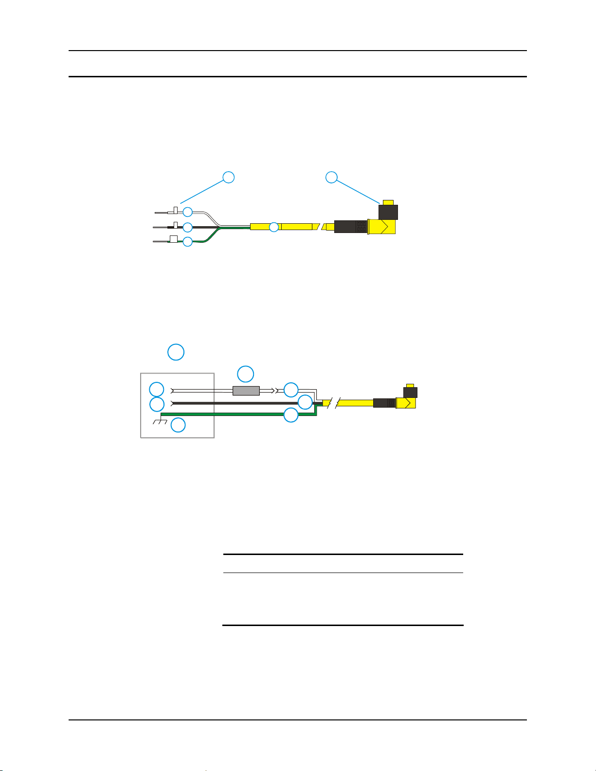
Power Supply 71
Vehicle 12-80VDC Direct Connection
Note: Instructions for using this configuration are contained in “VX6 User’s Guide” section
titled “Installation”.
1. To Vehicle Battery
2. To Vehicle
1 2
+
3
-
4
GND
5
6
Figure 2-41 Direct Vehicle Power Connection Cable (12 Ft.)
Mounted Device
or UPS Battery
Pack
3. White (DC+)
4. Black (DC-)
5. Green (GND)
6. 12 – 80 VDC
1. Vehicle Electrical
System
1
2
3
4
5
6
7
8
2. 10 Amp Slow
Blow Fuse
3. DC +
4. DC -
5. Vehicle Chassis
6. Red / White
7. Red /Black
8. Green
Figure 2-42 Connecting the Power Cable to the Vehicle
Note: Correct electrical polarity is required for safe and proper installation. Connecting the
cable to the VX6 with the polarity reversed will cau se the VX6 ’s fu se to b e blo wn. S ee the
following table for wire color-coding specifics.
Wiring color codes for LXE supplied DC input power cabling:
Vehicle Supply Wire Color
+12 - 80VDC (DC +) Red with White Stripe
Return (DC -) Red with Black Stripe
Vehicle Chassis (GND) Green
Figure 2-43 Vehicle Connection Wiring Color Codes
E-EQ-VX6RG-J VX6 Reference Guide
Page 94
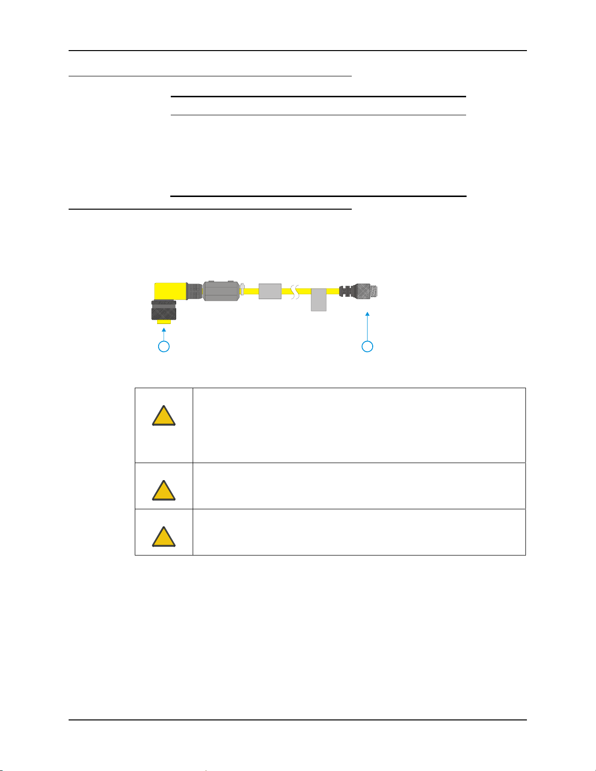
72 Power Supply
VX6 Input Power Specifications
Feature Specification
DC Input Voltage
Input Current 3.5 Amps
Input Fuse 10A Time Delay
Input Power Switch SPST 6 Amp 125VDC
12 - 80 VDC
Power Adapter Cable
LXE offers an adapter cable (part no. 9000A077CBLPWRADPTR) to adapt certain VX1, VX2 or
VX4 DC power supplies to the VX6. Please read and follow all cautions in the “VX6 User’s
Guide” to determine if your present power supply can be used with the VX6.
1. VX6 Connector
2. VX1/2/4 Power
Supply Connector
21
Caution:
!
Caution:
!
Caution:
!
Figure 2-44 Power Adapter Cable, VX1/2/4 to VX6
For use only with VX1/2/4 DC power cables with yellow colored cable containing
18AWG wires.
Do not use this cable with VX1/2/4 DC power cables with gray colored cable
containing 22AWG wires. These power cables must be replaced with a VX5/6/7
power cable.
When a DC power cable that is eight feet or longer is in a 12V application, there
may be an excessive voltage drop over the longer cable. If this occurs, a new
power cable is required.
Do not use this adapter with AC power supplies originally designed for the 1380,
1390, VX1, VX2 or VX4. These power supplies do not have sufficient power for
the VX6.
VX6 Reference Guide E-EQ-VX6RG-J
Page 95
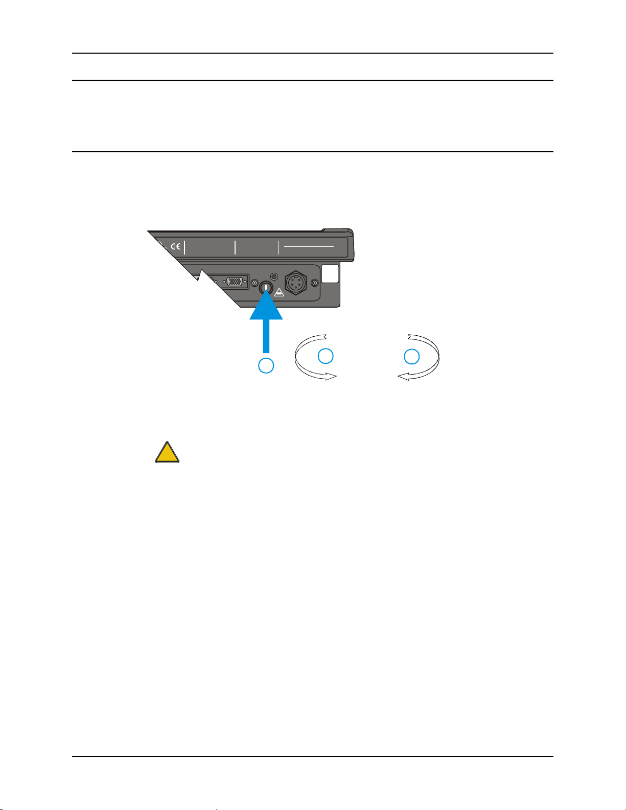
Power Supply 73
CMOS Battery
The LXE VX6 has a permanent 190 mAh Lithium battery installed to maintain time, date and
CMOS setup information. The lithium battery is not user serviceable and should last five years
with normal use before it requires replacement.
Fuse
The VX6 uses a 100V, 10A time delay (slow blow), high current interrupting rating fuse that is
externally accessible and user replaceable. Should it need replacement, replace with same size,
rating and type of fuse – Littlefuse 0234010 or Optifuse MSC-10A (5x20mm).
TENT 5862393
Caution:
!
THIS DEVICE COMPLIES WITH PART 15 OF THE FC C RULES.
OPERATION IS SUBJECT TO THE FOLLOWING TWO
CONDITIONS: (1) THIS DEVICE MAY NOT CAUSE HARMFUL
INTERFERENCE, AND (2) THIS DEVICE MUST ACCEP T AN Y
INTERFERENCE RECEIVED, INCLUDING INTERFERENCE
THAT MAY CAUSE UNDESIRED OPERATION.
This Class A digital apparatus complies with
Canadian ICE-003.
Cetappareil num de laClasseA est
érique
confirme l
orme NMB-003 du Canadaà n
CAUTION: For continues protection against risk of fire,
replace only with same type and rating of fuse.
ATTENTION: Pour ne pas compromette la preotection
contre les risques d'incendie , remplacer par un fusible
de mmes types de mmes caractristques nominales.êêé
1. Fuse
AUDIO
INPUT:
12-80VDC
ETHERNET /
USB
6A 72W
T10A, 125V
2. Twist in this
direction to
remove
3. Twist in this
direction to insert
2
3
1
Figure 2-45 Fuse Replacement
Fuse has voltage on it even when power is off. Always disconnect input power
before changing fuse.
E-EQ-VX6RG-J VX6 Reference Guide
Page 96

74 Power Supply
VX6 Reference Guide E-EQ-VX6RG-J
Page 97

Chapter 3 System Configuration
Introduction
There are several different aspects to the setup and configuration of the VX6. Many of the setup
and configuration settings are dependent upon the optional features such as hardware and software
installed on the unit. The examples found in this chapter are to be used as examples only, the
configuration of your specific VX6 computer may vary. The following sections provide a general
reference for the configuration of the VX6 and some of its optional features.
Your VX6 operating system may be Windows CE .NET 4.2 or Windows CE 5.0. The VX6
operating system is displayed on the Desktop as Windows CE .NET or Windows CE. This is the
factory default value for the Desktop Display Background.
This chapter presents information and procedures for Windows CE 5.0 only. Windows CE .NET
4.2 information and procedures are contained in Appendix C, “VX6 CE .NET 4.2”.
Windows CE Operating System
For general use instruction, please refer to commercially available Windows CE
user’s guides or the Windows CE on-line Help application installed with the VX6.
This chapter’s contents assume the system administrator is familiar with Microsoft Windows
options and capabilities loaded on most standard Windows computers.
Therefore, the sections that follow describe only those Windows capabilities that are unique to the
VX6 and its Windows CE environment.
Wireless Network Configuration
All radio configuration is included in Chapter 5, “Wireless Network Configuration”.
Warmboot
A warmboot reboots the computer without erasing any registry data. However, any applications
installed to RAM are lost, as is all data in RAM. This happens because the operating system is
stored on the flash drive, but must be loaded into RAM to run.
All registry configurations are automatically preserved. Any applications stored as .CAB files in
the System directory and configured in the registry to persist are reinstalled on boot up by the
Launch utility.
Coldboot
A coldboot reboots the computer, erases all registry data and returns the computer to factory
default settings. In order to be preserved, applications and data must be stored in the System
folder. Registry information is not preserved. Only factory default applications and drivers stored
as .CAB files in the System directory are loaded by Launch.
A cold boot is initiated by running the Coldboot application in the \Windows directory. This
application automatically cold boots the VX6, erasing any customer applied registry changes and
returning the VX6 to its factory settings.
E-EQ-VX6RG-J VX6 Reference Guide
Page 98

76 Installed Software
Installed Software
When you order a VX6 you receive the software files required by the separate programs needed
for operation and radio communication. The files are loaded by LXE and stored in subdirectories
in the VX6.
This section lists the contents of the subdirectories and the general function of the files. Files
installed in each VX6 are specific to the intended function of the VX6.
Files installed in each VX6 configured for an RF environment contain PCMCIA card radio
specific drivers – the drivers for each type of radio are specific to the manufacturer (e.g. Summit,
Cisco, Symbol) for the radios installed in the RF environment and are not interchangeable.
Software Load
The software loaded on the mobile computer consists of Windows CE 5.0 OS, hardware-specific
OEM Adaptation Layer, device drivers, Internet Explorer 6.0 for Windows CE browser and
utilities. The software supported is summarized below:
Operating System
• Full Operating System License: Includes all operating system components, including
Windows CE 5.0 kernel, file system, communications, connectivity (for remote APIs),
device drivers, events and messaging, graphics, keyboard and touchscreen input, window
management, and common controls.
Network and Device Drivers
Bluetooth (Optional)
Wavelink Avalanche (Optional)
LXE AppLock
Java (Optional)
• Java executables and browser components are handled by the Java option (when installed).
Terminal Emulation (Optional)
• RFTerm (VT220, TN5250, TN3270). Runs automatically at the conclusion of each reboot
(if installed).
LXE API Routines (see “Accessories” for the LXE SDK Kit part number)
Note: Please contact your LXE representative for software updates and CAB files as they are
released by LXE.
Software Applications
The following applications are included:
• WordPad (was PocketWord in previous versions of Windows CE)
• Word Viewer
• Excel Viewer
• PDF Viewer
VX6 Reference Guide E-EQ-VX6RG-J
Page 99

Installed Software 77
• Image Viewer
• Scanner Wedge (LXE developed)
• ActiveSync
• Transcriber
• Media Player
• Internet Explorer
Note that the viewer applications allow viewing documents, but not editing them.
Java (Optional)
Installed by LXE. Files can be accessed by tapping Start | Programs | JEM-CE. Doubletap the
EVM icon to open the EVM Console. A folder of Java examples and Plug-ins is also installed
with the Java option. LXE does not support Java applications running on the mobile device.
LXE RFTerm (Optional)
Installed by LXE. The application can be accessed by tapping Start | Programs | RFTerm.
Please refer to “Setup Terminal Emulation Parameters” earlier in this guide for RFTerm quick
start instruction. Refer to the “RFTerm Reference Guide” on the LXE Manuals CD for complete
information and instruction.
AppLock
Installed by LXE. Application is setup by the Administrator by tapping Start | Settings | Control
Panel | Administration. Configuration parameters are specified by the AppLock Administrator
for the mobile device end-user. AppLock is password protected by the Administrator. End-user
mode locks the end-user into the configured application or applications. The end user can still
reboot the mobile device and respond to dialog boxes. The administrator-specified application is
automatically launched and runs in full screen mode when the device boots up.
See Also: Chapter 6 “AppLock” for instruction.
Wavelink Avalanche Enabler (Optional)
The following features are supported by the Wavelink Avalanche Enabler when used in
conjunction with the Avalanche Molility Center (MC) Console.
After configuration, Enabler files are installed upon initial bootup and after a hard reset. Network
parameter configuration is supported for:
• IP address: DHCP or static IP
• RF network SSID
• DNS hosts (primary, secondary, tertiary)
• Subnet mask
• Enabler update
Related Manual: “Using Wavelink Avalanche on LXE Windows Computers”.
The VX6 has the Avalanche Enabler installation files loaded, but not installed, on the mobile
device when it is shipped from LXE. The installation files are located in the System folder on CE
devices. The installation application must be run manually the first time Avalanche is used.
E-EQ-VX6RG-J VX6 Reference Guide
Page 100

78 Installed Software
After the installation application is manually run, a reboot is necessary for the Enabler to begin
normal performance. Following this reboot, the Enabler will by default be an auto-launch
application. This behavior can be modified by accessing the Avalanche Update Settings panel
through the Enabler Interface. The designation of the mobile device to the Avalanche CE Manager
is LXE_VXC.
LXE CE devices manufactured before October 2006 must have their drivers and system files
upgraded before they can use the Avalanche Enabler functions. Please contact an LXE
representative for details on upgrading the mobile device baseline.
If the user is NOT using Wavelink Avalanche to manage their mobile device, the Enabler
should not be installed on the mobile device(s).
VX6 Reference Guide E-EQ-VX6RG-J
 Loading...