

Page 1
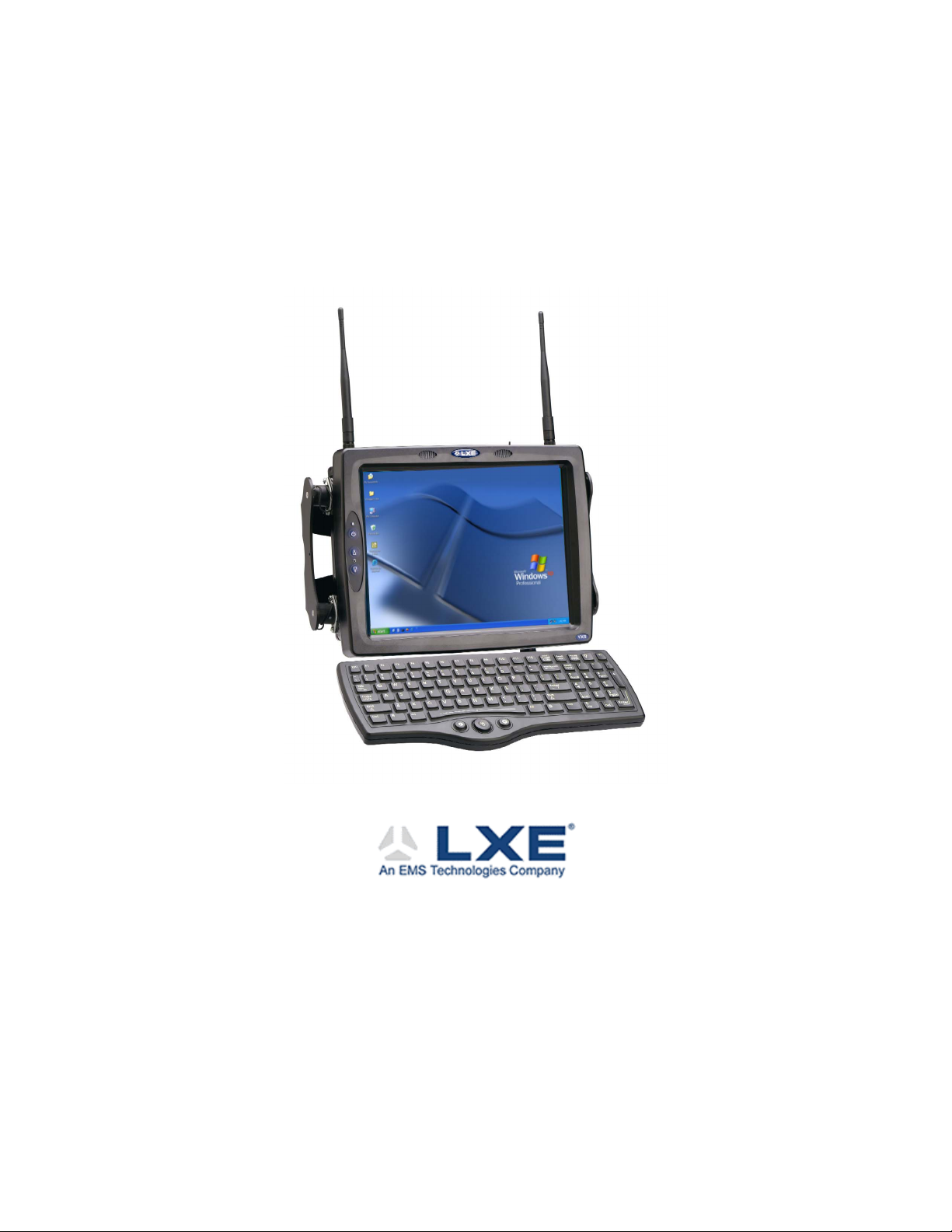
VX5 Reference Guide
Copyright © March 2004 by LXE Inc.
All Rights Reserved
E-EQ-VX5RG-A
Page 2

Notices
Notice:
LXE Inc. reserves the right to make improvements or changes in the products described in this manual at any time
without notice. While reasonable efforts have been made in the preparation of this document to assure its
accuracy, LXE assumes no liability resulting from any errors or omissions in this document, or from the use of the
information contained herein. Further, LXE Incorporated, reserves the right to revise this publication and to make
changes to it from time to time without any obligation to notify any person or organization of such revision or
changes.
Copyright Notice:
This manual is copyrighted. All rights are reserved. This document may not, in whole or in part, be copied,
photocopied, reproduced, translated or reduced to any electronic medium or machine-readable form without prior
consent, in writing, from LXE Inc.
Copyright © 2004 by LXE Inc. An EMS Technologies Company.
125 Technology Parkway, Norcross, GA 30092 U.S.A. (770) 447-4224
Trademarks:
LXE® is a registered trademark of LXE Inc.
Microsoft, Windows and the Windows logo are registered trademarks of Microsoft Corporation in the United
States and/or other countries.
All other brand or product names are trademarks or registered trademarks of their respective companies or
organizations. When this manual is in PDF format: "Acrobat ® Reader Copyright © 1987-2001 Adobe Systems
Incorporated. All rights reserved. Adobe, the Adobe logo, Acrobat, and the Acrobat logo are trademarks of Adobe
Systems Incorporated." applies.
Page 3

Table of Contents
CHAPTER 1 INTRODUCTION 1
Overview.................................................................................................................... 1
When to Use this Guide............................................................................................ 2
Document Conventions ............................................................................................................3
Quick Start................................................................................................................. 4
Components .............................................................................................................. 5
Data Entry.................................................................................................................. 7
Keyboard Data Entry ................................................................................................................7
Barcode Data Entry...................................................................................................................7
RS-232 Data Entry....................................................................................................................7
Touchscreen Entry....................................................................................................................8
Virtual Keyboard ......................................................................................................................9
Getting Help............................................................................................................. 10
Manuals and Accessories ...................................................................................... 10
Manuals...................................................................................................................................10
Accessories .............................................................................................................................10
CHAPTER 2 PHYSICAL DESCRIPTION AND LAYOUT 13
Hardware Configuration ......................................................................................... 13
System Hardware....................................................................................................................13
Central Processing Unit ..........................................................................................................14
AT Compatible Core Logic ....................................................................................................14
System Memory......................................................................................................................14
Upper Memory Block.............................................................................................................14
Flash BIOS..............................................................................................................................14
Video Subsystem ....................................................................................................................15
Power Supply..........................................................................................................................15
Uninterruptible Power Supply..............................................................................................15
Backup Battery.....................................................................................................................15
PCMCIA Slots ........................................................................................................................15
Power Management ................................................................................................................15
Physical Controls.................................................................................................... 16
On/Off Switch.........................................................................................................................16
External Connectors............................................................................................... 18
E-EQ-VX5RG-A VX5 Reference Guide
Page 4

ii Table of Contents
Scanner Serial Connector (COM1).........................................................................................19
Pinout ...................................................................................................................................19
Printer/PC Serial Connector (COM2).....................................................................................20
Pinout ...................................................................................................................................20
Keyboard/Mouse Connector...................................................................................................21
Pinout ...................................................................................................................................21
PS/2 Keyboard/Mouse Dongle Cable.....................................................................................22
D9 Male Connector ..............................................................................................................22
Pinout............................................................................................................................................. 22
PS/2 Keyboard Connector....................................................................................................23
Pinout............................................................................................................................................. 23
PS/2 Mouse ..........................................................................................................................23
Pinout............................................................................................................................................. 23
Ethernet/USB Connector ........................................................................................................24
Pinout ...................................................................................................................................24
Ethernet/USB Dongle Cable...................................................................................................25
D15 Female Connector.........................................................................................................25
Pinout............................................................................................................................................. 25
USB Connector ....................................................................................................................26
Pinout............................................................................................................................................. 26
RJ45 Connector ....................................................................................................................26
Pinout............................................................................................................................................. 26
Audio Connector.....................................................................................................................27
Pinout ...................................................................................................................................27
Power Supply Connector ........................................................................................................28
Pinout ...................................................................................................................................28
UPS Battery Pack Connectors ................................................................................................29
Input .....................................................................................................................................29
Pinout............................................................................................................................................. 29
Output...................................................................................................................................29
Pinout............................................................................................................................................. 29
UPS Battery Extension Cable Connectors..............................................................................30
Input .....................................................................................................................................30
Pinout............................................................................................................................................. 30
Output...................................................................................................................................30
Pinout............................................................................................................................................. 30
Antenna Connector .................................................................................................................31
Spread Spectrum RF Antenna Connector Pin ......................................................................31
Vehicle Remote Antenna Mount..........................................................................................31
Internal USB Port ...................................................................................................................32
Pinout ...................................................................................................................................32
The Keyboards ........................................................................................................ 33
The 95-key QWERTY Keyboard with Pointing Device ........................................................34
Key Maps .............................................................................................................................34
NumLock and the VX5.................................................................................................................. 34
CapsLock, Scroll Lock and the VX5 ............................................................................................. 34
VX5 Reference Guide E-EQ-VX5RG-A
Page 5

Table of Contents iii
Keyboard Backlight..............................................................................................................35
The 60-key QWERTY Keyboard ...........................................................................................36
Key Maps .............................................................................................................................36
Unused Key Functions .........................................................................................................36
NumLock and the VX5 ........................................................................................................37
Keyboard Backlight..............................................................................................................37
Keyboard LEDs....................................................................................................................37
CAPS LED..................................................................................................................................... 37
Secondary Keys LED..................................................................................................................... 38
Control Keys ........................................................................................................................39
General Windows Keyboard Shortcuts ..................................................................................40
PS/2 Keyboard/Mouse............................................................................................................41
Virtual Keyboard ....................................................................................................................41
The Display.............................................................................................................. 42
Cleaning the Display ..............................................................................................................42
Touchscreen............................................................................................................................42
Factory Default Settings......................................................................................... 42
PCMCIA/CardBus and ATA Slots .......................................................................... 43
PCMCIA Slots ........................................................................................................................43
PCMCIA Pinout ...................................................................................................................44
Install PCMCIA Cards .........................................................................................................45
Install the 2.4GHz Type II PCMCIA Radio .................................................................................. 45
ATA Slot.................................................................................................................................47
Install an ATA Card .............................................................................................................47
CHAPTER 3 POWER SUPPLY 49
Introduction ............................................................................................................. 49
External Power Supply ........................................................................................... 49
Specifications..........................................................................................................................50
Environmental Specifications.................................................................................................51
CMOS Battery.......................................................................................................... 51
Vehicle 12-80VDC Direct Connection.................................................................... 52
VX5 Input Power Specifications ............................................................................................53
Fuse ......................................................................................................................... 53
HAPTER 4 SYSTEM CONFIGURATION 55
C
Introduction ............................................................................................................. 55
BIOS Setup .............................................................................................................. 55
Windows Management Instrumentation.................................................................................56
Accessing the BIOS Setup......................................................................................................57
E-EQ-VX5RG-A VX5 Reference Guide
Page 6

iv Table of Contents
Using the Keypad ...................................................................................................................57
BIOS Setup Default Values by Option...................................................................................58
Main Menu Options................................................................................................................59
Legacy Diskette (A and B)...................................................................................................59
Primary and Secondary Master and Slave Drives................................................................60
Advanced Menu Options ........................................................................................................61
Advanced Chipset Control ...................................................................................................61
PCI Configuration ................................................................................................................61
Keyboard Features................................................................................................................62
NumLock ....................................................................................................................................... 62
Keyclick ......................................................................................................................................... 62
I/O Device Configuration.....................................................................................................63
Serial Port (A and B)...................................................................................................................... 63
Onboard LPT ................................................................................................................................. 63
USB Port / USB Host Controller ...................................................................................................63
USB BIOS Legacy Support ........................................................................................................... 63
Security...................................................................................................................................64
Power ......................................................................................................................................64
Boot.........................................................................................................................................64
Floppy Check .......................................................................................................................64
Summary Screen...................................................................................................................64
Quickboot Mode...................................................................................................................64
Dark Boot .............................................................................................................................64
Boot Device Priority.............................................................................................................65
Onboard LAN RPL ROM ....................................................................................................65
Exit Menu Options..................................................................................................................66
Exit Saving Changes ............................................................................................................66
Exit Discarding Changes......................................................................................................66
Load Setup Defaults .............................................................................................................66
Discard Changes...................................................................................................................66
Save Changes .......................................................................................................................66
Serial Port Pin 9 ...................................................................................................... 67
VMT Keyboard Backlighting .................................................................................. 68
Microsoft Windows Setup and Configuration ...................................................... 68
Microsoft Windows License Agreement (First Boot) ............................................................69
Microsoft Windows 2000.....................................................................................................69
Microsoft Windows XP........................................................................................................69
Drive C Directory Structure ...................................................................................................70
Software Loaded on Drive C................................................................................................70
Microsoft Windows Configuration.........................................................................................72
Touchscreen............................................................................................................ 73
Calibrating the Touchscreen...................................................................................................73
Configuring Right Click on the Touchscreen.........................................................................75
Disabling the Touch Screen....................................................................................................75
VX5 Reference Guide E-EQ-VX5RG-A
Page 7

Table of Contents v
Network Configuration ........................................................................................... 76
2.4 GHz Wireless Radios........................................................................................................76
Ethernet Connector .................................................................................................................76
VX5 Delivered with No Hard Drive ......................................................................... 77
VX5 Delivered with No OS...................................................................................... 78
Installing Microsoft Windows with Norton Ghost .................................................................78
Microsoft Windows 2000.....................................................................................................78
Microsoft Windows XP........................................................................................................80
Installing Microsoft Windows Over a Network .....................................................................82
Using a PCMCIA Network Card .........................................................................................82
Using the Ethernet Port ........................................................................................................85
Installing Microsoft Windows From a CD .............................................................................86
The VX5 Drivers CD-ROM....................................................................................... 87
CHAPTER 5 RF NETWORK CONFIGURATION 89
Introduction ............................................................................................................. 89
Cisco Radio ............................................................................................................. 90
Configuration..........................................................................................................................90
Profile Properties Screens ....................................................................................................93
Encryption...............................................................................................................................97
Static WEP ...........................................................................................................................98
LEAP....................................................................................................................................99
Diagnostics ...........................................................................................................................100
Updating Firmware...............................................................................................................101
Symbol Radio ........................................................................................................ 102
Configuration........................................................................................................................102
Encryption.............................................................................................................................105
Diagnostics ...........................................................................................................................107
Updating Firmware...............................................................................................................110
Troubleshooting.................................................................................................... 111
HAPTER 6 TROUBLESHOOTING 113
C
Problem Determination Tips ................................................................................ 113
Startup Problems .................................................................................................. 114
Bypassing Microsoft Windows Startup................................................................................115
Verifying Boot Order............................................................................................................116
Setting System Time and Date .............................................................................................116
Hardware Problems .............................................................................................. 117
Power Source ........................................................................................................................117
E-EQ-VX5RG-A VX5 Reference Guide
Page 8

vi Table of Contents
Keyboard...............................................................................................................................118
Display..................................................................................................................................118
Hard Disk Drive....................................................................................................................118
PCMCIA Cards.....................................................................................................................119
Memory Conflicts.................................................................................................................119
IRQ Assignments..................................................................................................................120
Optional Devices ..................................................................................................................121
Radio and Network Problems .............................................................................. 122
2.4 GHz Wireless Network...................................................................................................122
Ethernet Connection .............................................................................................................122
Software Related Problems.................................................................................. 123
Determining Software Revision ...........................................................................................123
System Testing ..................................................................................................... 124
Power On Self Test (POST) .................................................................................................124
POST Error Messages ........................................................................................................124
POST Informational Messages...........................................................................................127
If You Need Further Assistance........................................................................... 128
Before You Call....................................................................................................................128
APPENDIX A KEY MAPS 129
95-key Keypad with Pointing Device................................................................... 129
Key Map 101-Key Equivalencies.........................................................................................129
60-key Standard Keypad ...................................................................................... 130
Key Map 101-Key Equivalencies.......................................................................... 131
PPENDIX B TECHNICAL SPECIFICATIONS 137
A
Physical Specifications ........................................................................................ 137
Environmental Specifications.............................................................................. 138
Display Specifications ..........................................................................................................139
UPS Battery Pack Specifications..........................................................................................139
Radio Specifications............................................................................................. 140
PCMCIA Cisco 2.4GHz Type II ..........................................................................................140
PCMCIA Symbol 11Mb 2.4GHz Type II.............................................................................140
INDEX 141
VX5 Reference Guide E-EQ-VX5RG-A
Page 9

Table of Contents vii
Illustrations
Figure 1-1 VX5 Components............................................................................................................................... 5
Figure 1-2 VX5 Control Panel.............................................................................................................................6
Figure 1-3 VX5 Access Panel.............................................................................................................................. 6
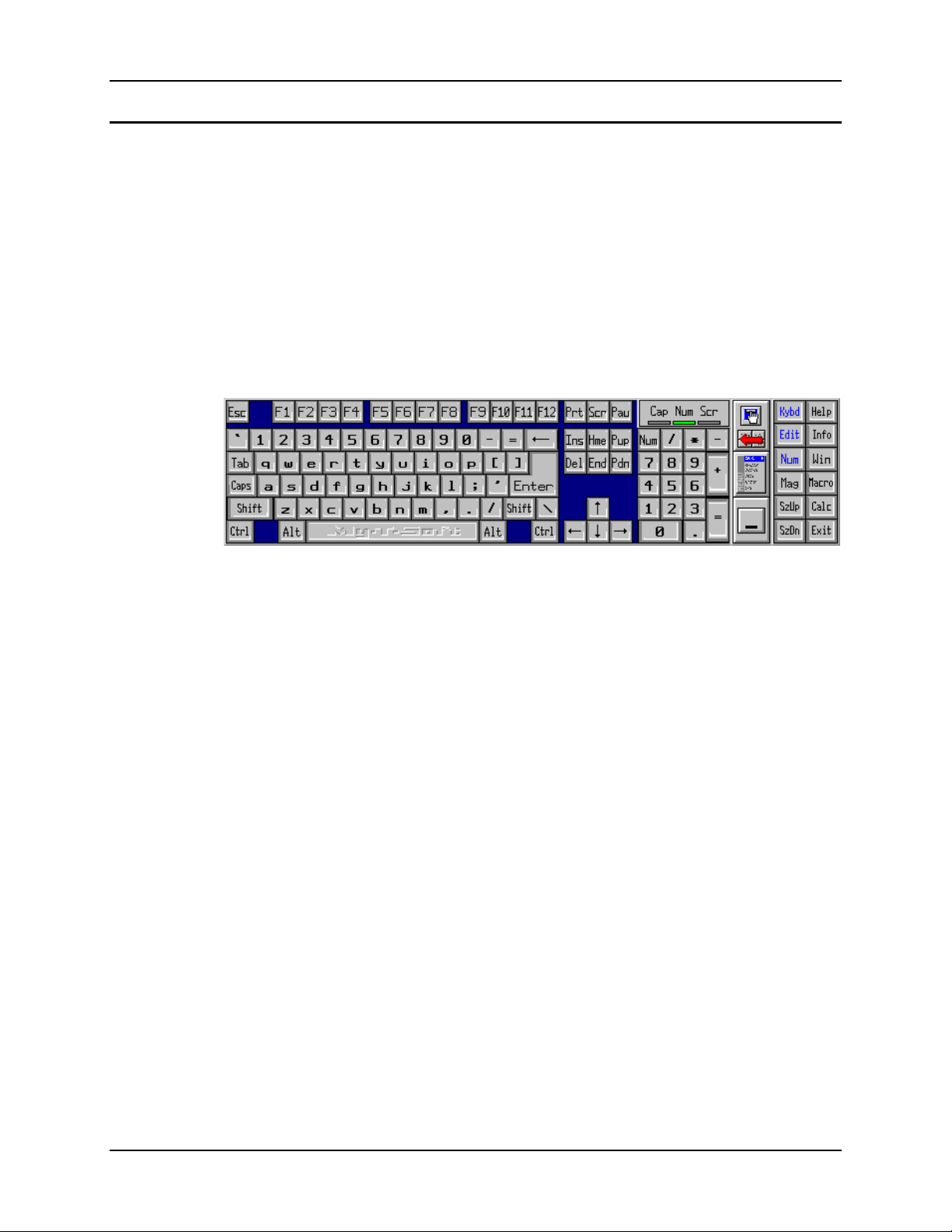
Figure 1-4 Virtual Keyboard, Typical Configuration ..........................................................................................9
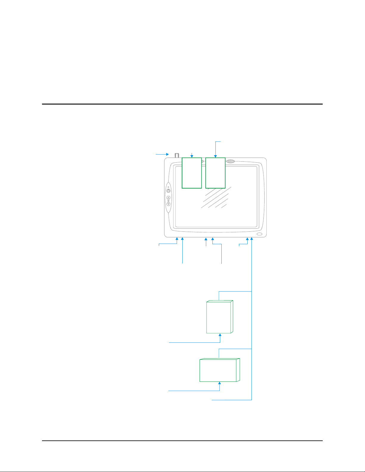
Figure 2-1 VX5 Hardware Configuration..........................................................................................................13
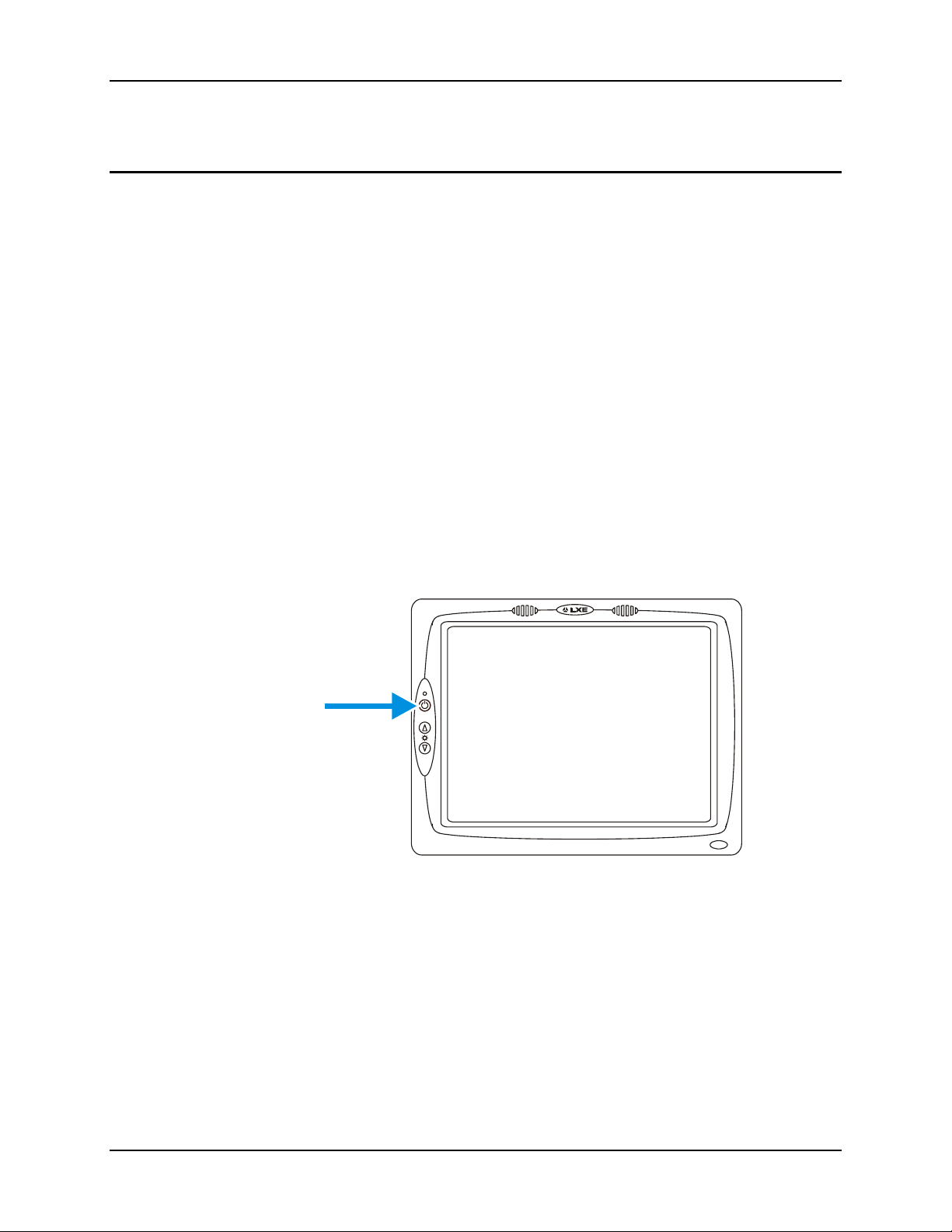
Figure 2-2 The Power (On/Off) Switch .............................................................................................................16
Figure 2-3 Scanner Serial Connector (COM1) .................................................................................................. 19
Figure 2-4 The Printer/PC Serial Connector (COM2) .......................................................................................20
Figure 2-5 VX5 Keyboard Connector and External Keyboard Cable Connector.............................................. 21
Figure 2-6 VX5 PS/2 Keyboard/Mouse Dongle Cable...................................................................................... 22
Figure 2-7 D9 Male Connector ..........................................................................................................................22
Figure 2-8 PS/2 Keyboard Connector................................................................................................................23
Figure 2-9 PS/2 Mouse Connector.....................................................................................................................23
Figure 2-10 VX5 USB Connector and External USB Adapter Cable Connector..............................................24
Figure 2-11 VX5 Ethernet/USB Dongle Cable..................................................................................................25
Figure 2-12 D15 Female Connector...................................................................................................................25
Figure 2-13 Dongle Cable USB Port ................................................................................................................. 26
Figure 2-14 Dongle Cable Ethernet Port............................................................................................................26
Figure 2-15 VX5 Audio Jack for External Speaker or Headphones..................................................................27
Figure 2-16 The Power Connector.....................................................................................................................28
Figure 2-17 The UPS Battery Pack Input Connector.........................................................................................29
Figure 2-18 The UPS Battery Pack Output Connector ......................................................................................29
Figure 2-19 The UPS Battery Extension Cable Input Connector ......................................................................30
Figure 2-20 The UPS Battery Extension Cable Output Connector....................................................................30
Figure 2-21 2.4GHz Antennas ...........................................................................................................................31
Figure 2-22 RF Antenna SS Connector .............................................................................................................31
Figure 2-23 Dongle Cable USB Port ................................................................................................................. 32
Figure 2-24 The LXE VMT Keyboards with Cable ..........................................................................................33
Figure 2-25 The 95-key QWERTY Keyboard...................................................................................................34
Figure 2-26 The 60-key QWERTY Keyboard...................................................................................................36
Figure 2-27 Keyboard LEDs..............................................................................................................................37
Figure 2-28 The CapsLock Key.........................................................................................................................37
Figure 2-29 The Secondary Key ........................................................................................................................38
Figure 2-30 The VMT Keyboard Display Controls...........................................................................................39
Figure 2-31 Virtual Keyboard, Typical Configuration ......................................................................................41
Figure 2-32 The PCMCIA and ATA Slots ........................................................................................................43
Figure 2-33 Inserting the 2.4GHz Type II PCMCIA Radio...............................................................................45
Figure 2-34 Cisco Antenna Cable Connections.................................................................................................46
Figure 2-35 Symbol 11Mb Antenna Cable Connections ...................................................................................46
Figure 2-36 Inserting the ATA Card..................................................................................................................47
Figure 3-1 Optional Power Supply Cable..........................................................................................................49
Figure 3-2 Direct Vehicle Power Connection Cable (12 Ft.).............................................................................52
Figure 3-3 Connecting the Power Cable to the Vehicle.....................................................................................52
Figure 3-4 Vehicle Connection Wiring Color Codes.........................................................................................52
Figure 3-5 Fuse Replacement ............................................................................................................................53
Figure 4-1 DIP Switch Location ........................................................................................................................67
Figure 4-2 Touchscreen Calibration ..................................................................................................................73
Figure 4-3 Touchscreen Calibration ..................................................................................................................74
Figure 4-4 Touch Panel Configuration ..............................................................................................................75
Figure 4-5 Hard Drive Sled................................................................................................................................77
Figure 4-6 Hard Drive Connector Pins ..............................................................................................................77
E-EQ-VX5RG-A VX5 Reference Guide
Page 10

viii Table of Contents
Figure 5-1 Cisco Aironet Client Utility .............................................................................................................90
Figure 5-2 Cisco Profile Selection Screen .........................................................................................................91
Figure 5-3 Cisco Profile Selection Management Screen ...................................................................................91
Figure 5-4 Cisco Profile Manager Screen..........................................................................................................92
Figure 5-5 Cisco Properties - System Parameters.............................................................................................. 93
Figure 5-6 Cisco Properties - RF Network ........................................................................................................94
Figure 5-7 Cisco Properties - Advanced (Infrastructure)...................................................................................95
Figure 5-8 Cisco Properties - Advanced (Ad Hoc)............................................................................................ 96
Figure 5-9 Cisco Properties – Network Security ............................................................................................... 97
Figure 5-10 Cisco Properties – Static WEP .......................................................................................................98
Figure 5-11 Cisco Properties – LEAP Settings..................................................................................................99
Figure 5-12 Cisco Link Status Meter...............................................................................................................100
Figure 5-13 Cisco Preferences .........................................................................................................................101
Figure 5-14 Symbol WLAN Profiles...............................................................................................................102
Figure 5-15 Symbol Profile – Mode ................................................................................................................103
Figure 5-16 Symbol Profile – IP Configuration...............................................................................................104
Figure 5-17 Symbol Profile – Power ............................................................................................................... 104
Figure 5-18 Symbol Profile – 40 bit Encryption..............................................................................................105
Figure 5-19 Symbol Profile – 128 bit Encryption............................................................................................106
Figure 5-20 Symbol Status – Signal ................................................................................................................107
Figure 5-21 Symbol Status – Information........................................................................................................108
Figure 5-22 Symbol Status – IP Status ............................................................................................................108
Figure 5-23 Symbol Status – Ping Test ...........................................................................................................109
Figure 5-24 Symbol Status – AP’s...................................................................................................................109
Figure 5-25 Symbol – Available WLANs .......................................................................................................110
Figure 5-26 Windows Wireless Network Properties .......................................................................................111
Figure A-1 95-Key VMT QWERTY Keyboard .............................................................................................. 129
Figure A-2 60-Key VMT QWERTY Keyboard .............................................................................................. 130
VX5 Reference Guide E-EQ-VX5RG-A
Page 11
Overview
Chapter 1 Introduction
The VX5 Vehicle Mount Computer (VMC) is a rugged, vehicle mounted, PC (Personal
Computer) running a Microsoft® Windows® operating system and capable of wireless data
communications from a fork-lift truck or any properly configured vehicle. The VX5 provides the
power and functionality of a desktop computer in a vehicle mounted unit, with a wide range of
options:
CPU 933MHz PIII
Memory 256 or 512MB SDRAM
Display
Network
connectivity
Audio Speakers in front bezel, audio jack for headset with microphone
Storage media
Operating
system
Other options Extended temperature version (512MB RAM only)
For information on installing Microsoft Windows on a VX5 ordered with no operating system,
please refer to Chapter 4, “System Configuration”, section titled “VX5 Delivered with No OS”.
Microsoft Windows License Agreement (First Boot)
If your VX5 is shipped with a Microsoft Windows operating system pre-installed, it is
necessary to complete the Windows licensing/registration screens when starting the
VX5 for the first time. To complete this information, you need the Microsoft
Windows software/product key that was included with the VX5.
Indoor or Outdoor 12.1” display, integrated Touchscreen, adjustable
brightness
2.4 Wireless LAN radio (single or dual antenna)
Ethernet port
Removable rotating
Compact Flash
PCMCIA
Microsoft Windows 2000 or XP Professional
No operating system
Please refer to Chapter 4 “System Configuration”, section titled “Microsoft Windows License
Agreement (First Boot)” for instruction.
The “VX5 User’s Guide” is directed toward the VX5 user. It is delivered on the LXE
Documentation CD. It contains safety warnings, descriptions of the controls and
connectors, instruction on installing antennas, and day to day operation.
E-EQ-VX5RG-A VX5 Reference Guide
Page 12

2 When to Use this Guide
When to Use this Guide
As the reference for LXE's VX5 equipped with a Microsoft Windows operating system, this guide
provides detailed information on its features and functionality. Use this guide as you would any
other source book -- reading portions to learn about the VX5, and then referring to it when you
need more information about a particular subject.
This chapter, “Introduction”, briefly describes this reference guide structure, contains setup and
installation instruction, briefly describes data entry processes, and explains how to get help.
Chapter 2 “Physical Description and Layout” describes the function and layout of the controls
and connectors on the VX5.
Chapter 3 “Power Supply” describes AC power and DC power connections.
Chapter 4 “System Configuration” takes you through the BIOS Setup, hardware configuration,
VX5 file structure, system files and Microsoft Windows configuration.
Chapter 5 "RF Network Configuration" presents information and instruction for using and
managing radio cards in the VX5.
Chapter 6 “Troubleshooting” is split into several areas. The solution may be found in one area
or it may be a combination of the solutions in several areas. It contains a listing of Power On Self
Test (POST) messages and run time messages.
Appendix A “Key Maps” describes the keypress sequences for the LXE VMC keyboard.
Appendix B “Technical Specifications” lists technical specifications including physical,
environmental, display and the radios.
VX5 Reference Guide E-EQ-VX5RG-A
Page 13
When to Use this Guide 3
Document Conventions
This reference guide uses the following document conventions:
ALL CAPS
Menu|Choice
"Quotes"
< >
ATTENTION
!
All caps are used to represent disk directories, file names, and application
names.
Rather than use the phrase "choose the Save command from the File menu",
this guide uses the convention "choose File|Save".
Indicates the title of a book, chapter or a section within a chapter (for example,
"Document Conventions").
Indicates a key on the keyboard (for example, <Enter> ).
Indicates a reference to other documentation.
Differences in operation or commands due to radio type.
Differences in operation or commands due to operating system.
Keyword that indicates vital or pivotal information to follow.
Attention symbol that indicates vital or pivotal information to follow. Also,
when marked on product, means to refer to the manual or user’s guide.
International fuse replacement symbol. When marked on the product, the label
includes fuse ratings in volts (v) and amperes (a) for the product.
Note: Keyword that indicates immediately relevant information.
Caution
!
WARNING
Keyword that indicates a potentially hazardous situation, which, if not avoided,
may result in minor or moderate injury.
Keyword that indicates a potentially hazardous situation, which, if not avoided,
could result in death or serious injury.
!
DANGER
Keyword that indicates an imminent hazardous situation, which, if not avoided,
will result in death or serious injury.
!
E-EQ-VX5RG-A VX5 Reference Guide
Page 14

4 Quick Start
Quick Start
This section’s instructions are based on the assumption that your new system is pre-configured
and requires only accessory installation (e.g. antenna, external keyboard and/or barcode scanner)
and a power source.
In general, the sequence of events is:
1. Install Vehicle Mounting Bracket (and keyboard mounting bracket) on vehicle.
2. Secure VX5 in Mounting Bracket Assembly.
3. Connect power cable to the VX5. The power cable can also be connected to a UPS
battery pack, which is then connected to the VX5.
4. Connect power cable to the VX5.
5. Connect accessories to VX5, e.g. scanner, antenna, keyboard.
6. Secure all cables to the VX5 with the Strain Relief Cable Clamps.
7. Turn the VX5 on.
The VX5 and its keyboard should be mounted in an area in the vehicle where it:
• Does not obstruct the vehicle driver's vision or safe vehicle operation.
• Can be easily accessed by anyone seated in the driver's seat.
VX5 Reference Guide E-EQ-VX5RG-A
Page 15
Components 5
V
A
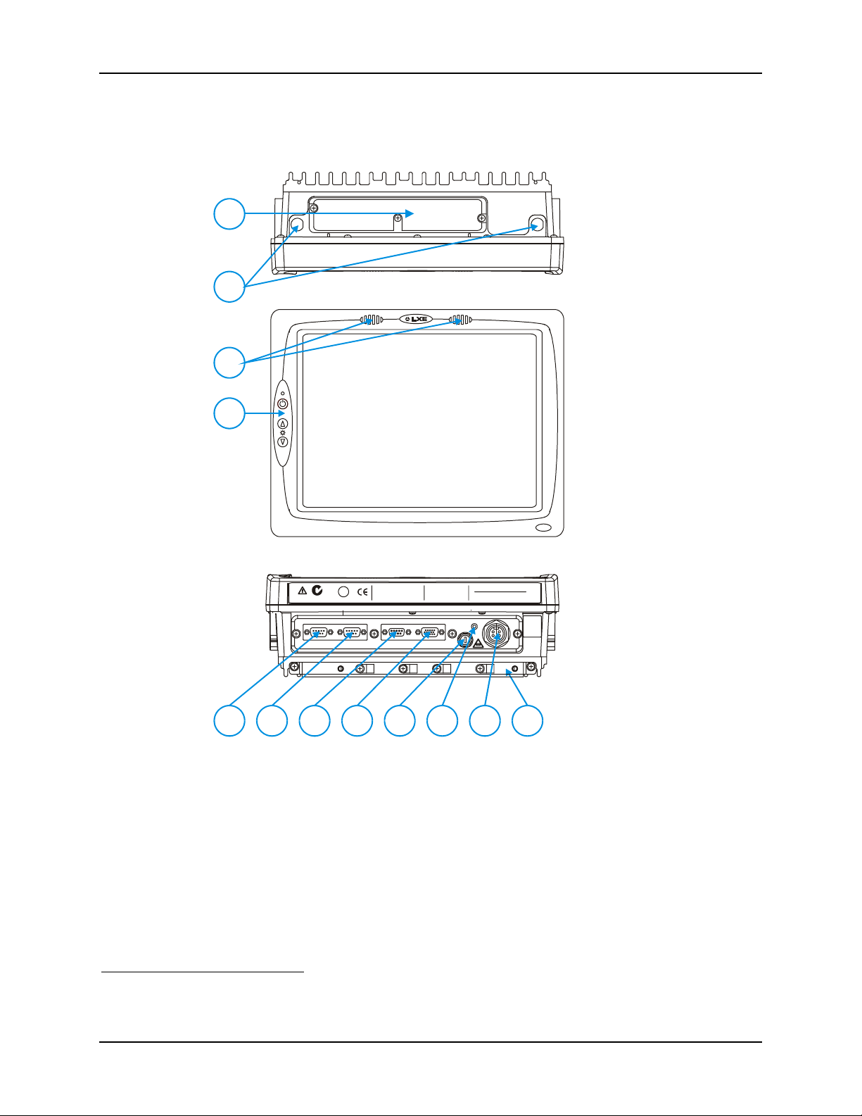
Components
1. Access Panel Cover
1
(See Following
Illustrations for Detail)
2. Antenna Connectors
or Hole Plugs
2
3. Speakers
4. Control Panel
3
(See Following
Illustrations for Detail)
4
5. COM1/Scanner
Connector
1
6. COM2 Connector
1
7. Keyboard/Mouse
Connector
X5
8. Ethernet/USB Cable
Connector
IP66
LISTED
I.T.E.
REFER TO
MANUAL
E-130794
N107
U
US
L
C
®
PRODUCT OF U.S.A. U.S. PATENT 5862393
COM2COM1 / SCANNER
THIS DEVICE COMPLIES WITH PART 15 OF THE FCC RULES.
OPERATION IS SUBJECT TO THE FOLLOWING TWO
CONDITIONS: (1) THIS DEVICE MAY NOT CAUSE HARMFUL
INTERFERENCE, AND (2) THIS DEVICE MUST ACCEPT ANY
INTERFERENCE RECEIVED, INCLUDING INTERFERENCE
THAT MAY CAUSE UNDESIRED OPERATION.
KEYBOARD /
MOUSE
This Class A digital apparatus complies with
Canadian ICE-003.
Cet appareil num de la Classe A est
confirme l
ETHERNET /
USB
érique
orme NMB-003 du Canadaà n
CAUTION: For continues protection against risk of fire,
replace only with same type and rating of f use.
ATTENTION: Pour ne pas compromette la preotecti on
contre les risques d'incendie, rempla cer par un fusible
de m mes ty pes de m mes caract ri stques nominales.êêé
UDIO
INPUT:
12-80VDC
6A 72W
T10A, 125V
9. Fuse
10. Audio Connector
11. Power Cable
Connector
12. Cable Strain Relief
5
10
9876
1211
Bracket and Clips
Figure 1-1 VX5 Components
1
COM1 is configured with Pin 9 +5V. COM2 is configured with Pin 9 RI. Refer to Chapter 4,
“System Configuration” for more information.
E-EQ-VX5RG-A VX5 Reference Guide
Page 16
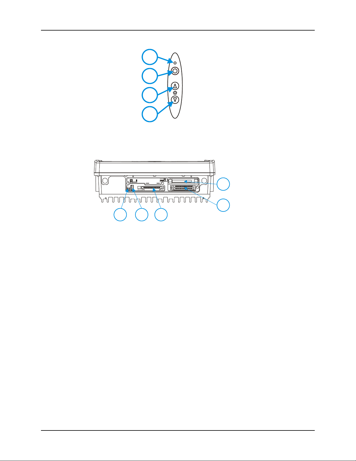
6 Components
1
2
1. Power LED
2. Power Switch
3. Brightness Increase
3
4. Brightness
Decrease
4
Figure 1-2 VX5 Control Panel
COM1 COM2
SCANNER
SERIAL
IDE DRIVE
CARD BUS A
CARD BUS B
USB
PCMCIA/CF ATA
21
3
1. COM Port DIP
Switches
2. USB Connector
5
3. ATA Slot
(PCMCIA/Compact
Flash)
4
4. CardBus (PCMCIA)
Slots
5. IDE Drive
Figure 1-3 VX5 Access Panel
Note: The tethered access panel cover is not shown in the illustration above.
VX5 Reference Guide E-EQ-VX5RG-A
Page 17

Data Entry 7
Data Entry
You can enter data into the VX5 through several different methods. A tethered scanner connected
to the COM1 serial port provides barcode data entry, the serial ports are used to input/output data,
keyboards provide manual entry and the touchscreen also provides manual entry (simulating a
desktop PC’s mouse).
Keyboard Data Entry
Refer to “Appendix A - Key Maps” for 101-key keyboard equivalent
keypresses.
The keyboard is used to manually input data that is not collected otherwise. Almost any function
that a full sized computer keyboard can provide is duplicated on the LXE VMT keyboard but it
may take a few more keystrokes to accomplish a keyed task.
When using the LXE 60-key keyboard. almost every key has two or three different functions. The
primary alpha or numeric character is printed on the key.
nd
For example, when the <2
nd
the <2
character is printed above the corresponding key.
> character i.e. <2nd> + <F1> toggles the CAPS Lock function. The specific <2nd>
> key is selected pressing the desired second-function key produces
Please refer to “Appendix A - Key Maps” for instruction on the specific keypresses to access all
PC-compatible keyboard functions.
Barcode Data Entry
The VX5 supports an accessory barcode label reading device. Keyboard data entries can be mixed
with barcode data entries. Any scanner that decodes the barcode internally and outputs an RS-232
data stream may be used. COM port 1 is designed to be used with a hand held tethered barcode
scanner.
COM1 is set to +5V on pin 9 up to accept input from a barcode scanner by default. COM2 pin
9 is set to RI. To change the default settings for pin 9 on either port, refer to Chapter 4:
“System Configuration” section titled “Serial Port Pin 9” for details.
RS-232 Data Entry
The VX5 accepts input from an RS-232 device connected to either RS-232 port, COM1 or
COM2. The data is entered at the cursor position, and the data is subject to all of the barcode/RS232 input menu parameters, such as truncate.
E-EQ-VX5RG-A VX5 Reference Guide
Page 18

8 Data Entry
Touchscreen Entry
Note: The touch screen should be calibrated before initial use. See “Touchscreen
Calibration” in Chapter 4, “System Configuration”.
Note: Always use the point of the stylus for tapping or making strokes on the display. Never use
an actual pen, pencil or sharp object to write on the touch screen.
The touchscreen input performs the same function as the mouse that is used to point to and click
elements on a desk top computer. A stylus is used in the same manner as a mouse – single tap or
double tap to select menu options, drag the stylus across text to select, hold the stylus down to
activate slider bars, etcetera. Right click is accomplished via the <Ctrl> key, either as pressing of
the <Ctrl> key followed by a screen touch or holding the <Ctrl> key down flowed by a screen
touch. Please refer to “Configuring Right Click on the Touchscreen” in Chapter 4, “System
Configuration” for more details.
Note: For the 60-key keyboard, the right click MUST BE configured as holding the <Crtl> key
followed by a screen touch.
Hold the stylus as if it were a pen or pencil. Touch an element on the screen with the tip of the
stylus then remove the stylus from the screen. The touch screen responds to an actuation force
(touch) of up to 4 oz. of pressure.
The touch screen can be used in conjunction with the keyboard and scanner and an input/output
device connected to one of the VX5's serial ports.
• Touch the stylus to the field of the data entry form to receive the next data feed.
• The cursor begins to flash in the field.
• The unit is ready to accept data from either the keyboard, integrated scanner or a
device connected to a serial port.
Note: The touchscreen may be disabled. Please refer to “Disabling the Touchscreen” in
Chapter 4, “System Configuration” for details.
VX5 Reference Guide E-EQ-VX5RG-A
Page 19
Data Entry 9
Virtual Keyboard
The optional My-T-Soft software provides a virtual keyboard on the touchscreen. To start the
virtual keyboard, click on the My-T-Soft icon on the desktop or select Start|Programs|My-T-
Soft|My-T-Soft.
The virtual keyboard provides several configuration options, including:
• Keyboard size
• QWERTY vs. ABCD
• Standard 101 key format vs. Windows 104 key format
For more information on configuring the virtual keyboard, click on Start|Programs|My-TSoft|My-T-Soft Setup.
Figure 1-4 Virtual Keyboard, Typical Configuration
Virtual keyboards display the actual character the keypress outputs. For example, pressing the
<Shift> key on the virtual keyboard toggles the characters displayed on the keys between upper
and lower case.
Note: When the virtual keyboard is displayed, the physical keyboard is still active, if attached.
Therefore it is possible to input data from both keyboards.
E-EQ-VX5RG-A VX5 Reference Guide
Page 20

10 Getting Help
Getting Help
All LXE manuals are now available on one CD and they can also be viewed/downloaded
from the LXE website. Contact your LXE representative to obtain the LXE Manuals CD.
You can also get help from LXE by calling the telephone numbers listed on the LXE Manuals
CD, in the file titled "Contacting LXE". This information is also available on the LXE website
www.lxe.com.
Explanations of terms and acronyms used in this guide are located in the file titled "Glossary" on
the LXE Manuals CD.
Manuals and Accessories
Manuals
The following manuals are available on the LXE Manuals CD:
• VX5 User’s Guide
• RFTerm™ Reference Guide
• ORiNOCO IEEE User's Guide
• Contacting LXE
• LXE Technical Glossary
Accessories
VX5 Brackets
Bracket, U Style, VX5 VX5A001UBRACKET
Bracket, U Style w/ Integrated Keyboard Mount, VX5 VX5A001UBRKTWKBDMNT
Kit, VXX U-Bracket to VX5 Adapter VX5A002BRKTADPTKIT
Kit, VXX U-Bracket to VX5 Adapter w/ Keyboard Mount VX5A002BRKTADPKBDMNT
Bracket, RAM Mount VX5 VX5A003BRKTRAMMOUNT
Bracket, Combo RAM VMT Mount w/ Keyboard Mount, VX5 VX5A003BRKTRAMWKBMNT
Keyboard Brackets
Bracket, Keyboard, Integrated U Style, VX5 VX5A004BRKTKBDUMOUNT
Bracket, Keyboard, RAM Mount, VX5 VX7 9000A017BRKTKBDRAM
Bracket, Remote, Keyboard, LXE 9000A012BRKTRMTLXE
Bracket, Remote, Mouse Keyboard 9000A018BRKTMKBDRMT
Keyboards
Keyboard, LXE Standard, D9, ANSI/PC Overlay, QWERTY 9000A157KBDSTDD9ANSI
Keyboard, LXE Standard, D9, 5250 Overlay, QWERTY 9000A158KBDSTDD95250
Keyboard, LXE Standard, D9, 3270 Overlay, QWERTY 9000A159KBDSTDD93270
Keyboard, Rugged PC Style w/Mouse, PS2 D9 9000A160MOUSEKBDD9
VX5 Reference Guide E-EQ-VX5RG-A
Page 21

Manuals and Accessories 11
Data Cables
Cable Assembly, 6FT Remote, Antenna Mount, Non-Cond. 9000A278ANTREMOTE6
Cable Assembly, 8FT Remote, Antenna Mount, Non-Cond. 9000A279ANTREMOTE8
Cable, Combo D15 to USB and Ethernet Adapter 1 Ft 9000A071CBLD15USBETH
Cable, Keyboard/Mouse Dual PS2 Adapter 1 Ft 9000A072CBLD9DUALPS2
Cable, Printer/PC, D9 to D25 9000A053CBL6D9D25
Cable, PC, D9 to D9 9000A054CBL6D9D9
Cable, Zebra QL420 Printer 9000A062CBLD9COMTEC
Power Cables
Cable, Input Power, 12 FT, VX5 VX6 VX7 9000A073CBLPWR12FT
Power Supplies
Power Supply, External, AC, W/US Power Cord VX5 VX6 VX7 9000A317PSACUS
Power Supply, External, AC, No Power Cord VX5 VX6 VX7 9000A318PSACWW
UPS Battery and Cables
Battery, UPS Lead Acid, VX5 VX6 VX7 9000A378UPSBATTPACK
Cable, UPS Battery, Remote Mount Extender, 6 Ft 9000A074CBLUPSEXTNDR
Miscellaneous
Stylus, with Tethers and Sleeves, 5 Pack 9000A510STYLUS
Media BC-WEDGE DOS/Windows Taltech Floppy 9000A485BCWEDGEMEDIA
On-Screen Software Keyboard Windows 95 Through XP 11201 MY-T-SOFT
Protective Film, 12 in Display, 10 Pack, VX5 VX7 9000A511PROTFILM12IN
PCMCIA Compact Flash adapter 9000A106PCCCFADAPTR
Software, Drivers, VX5 VX5A477DRIVERS
Printers
Zebra, PA400, 240VAC, EC PA400-050-12100
Zebra, PA400, 120VAC, US PA400-050-11100
Zebra, PA400, 20-80VDC PA400-050-99100
Zebra, PT400, 240VAC, EC PT400-050-12100
Zebra, PT400, 120VAC, US PT400-050-11100
Zebra, PT400, 20-80VDC PT400-050-99100
E-EQ-VX5RG-A VX5 Reference Guide
Page 22

12 Manuals and Accessories
Scanners
Scanner, LS3203, Ext. Range, 8’ Cbl, US 8011LS3203ERC08DUS
Scanner, LS3203, Ext. Range, 8’ Cbl, EC 8011LS3203ERC08DEC
Scanner, LS3203, Ext. Range, 20’ Cbl, US 8011LS3203ERC20DUS
Scanner, LS3203, Ext. Range, 20’ Cbl, PS/2, US 8011LS3203ERC08PUS
Scanner, LS3203, Ext. Range, 8’ Cbl, PS/2 EC 8011LS3203ERC08PEC
Scanner, 530092IP, 7’ Cbl, WW 8110IP530092C07DWW
Scanner, 530092IP, 15’ Cbl, US 8110IP530092C15DUS
Scanner, Phase 302 Fuzzy Logic, 8’ Cbl, WW 8200A326SCNRP3028DA9F
Scanner, Phase 302 Fuzzy Logic, 20’ Cbl, US 8200A327SCNRP30220DA9F
Scanner, Phase 302 Fuzzy Logic, 8’ Cbl, PS/2, WW 8200A331SCNRP3028PS2
Scanner, P304PRO, 8’ Cbl, WW 8210A326SCNRP3048DA9F
Scanner, P304PRO, 20’ Cbl, US 8210A327PRO20D9F
Scanner, P304PRO, 20’ Cbl, US 8210A327SCNRP30420DA9F
Scanner, Powerscan, SR, 8’ Cbl, WW 8300A326SCNRPWRSR8DA9F
Scanner, Powerscan, SR, 12’ Cbl, US 8300A327SCNRPWRSR12DA9F
Scanner, Powerscan SR, 11’ Cbl, PS/2, US 8300A330SCNRPWRSR11PS2
Scanner, Powerscan, LR, 8’ Cbl, WW 8310A326SCNRPWRLR8DA9F
Scanner, Powerscan LR 12’ Cbl, US 8310A327SCNRPWRLR12DA9F
Scanner, Powerscan, LR, 12’ Cbl, PS/2, US 8310A330SCNRPWRLR11PS2
Scanner, Powerscan, XLR, 8’ Cbl, WW 8320A326SCNRPWRXLR8DA9F
Scanner, Powerscan XLR, 12’ Cbl, US 8320A327SCNRPWRXLR12DA9F
Scanner, Powerscan XLR, 12’ Cbl, PS/2, US 8320A330SCNRPWRXLR11PS2
VX5 Reference Guide E-EQ-VX5RG-A
Page 23
V
CMC
Chapter 2 Physical Description and Layout
Hardware Configuration
System Hardware
The VX5 hardware configuration is shown in the following figure.
Antenna
Connector
Serial
Connector
COM1 - Scanner
(9 pin male "D")
Any Type
I, II or III
PCMCIA
Card
Slot 0
&
Slot 1
Serial
Connector
COM2 - PRINTER
(9pin male "D")
Keyboard/
Mouse
Connector
Connector
P
Compact Flash w/
ATA
Slot
Connector
USB/
Ethernet
DC out (12V)
IA Card or
Adapter
X5
Audio
AC Adapter
AC in (120 - 240V)
Uninterruptible
Power
Supply (UPS)
DC in (12-80V)
DC in (12-80V)
Figure 2-1 VX5 Hardware Configuration
E-EQ-VX5RG-A VX5 Reference Guide
Page 24

14 Hardware Configuration
Central Processing Unit
The LXE VX5 contains an Intel Pentium III 933 MHz CPU.
AT Compatible Core Logic
The LXE VX5 utilizes AT-compatible core logic. The VX5 supports the following I/O
components:
• Two 9-pin RS-232 serial ports configured as:
o COM 1 - 03F8h; IRQ4 (SCANNER port),
o COM 2 - 02F8h; IRQ3 (PRINTER/PC port)
• Two CardBus slots (supporting Type I, II or III PCMCIA cards), accepts two (2)
Type II cards or one (1) Type III card.
• One slot for ATA memory cards supporting PCMCIA or compact flash format,
configured as secondary IDE.
• Primary IDE, usually an internal hard drive.
• LXE VMT or standard PS/2 keyboard (via a watertight connector).
• Two USB ports, conforming to USB 1.0 specifications
• One audio jack providing monaural audio output.
• Ethernet port via dongle cable.
Note: Using switches inside the user access panel, Pin 9 of COM1 and COM2 may be
configured to provide 5 volts DC to power a barcode scanner or RI for serial transfer.
System Memory
Main system memory is 256 or 512MB SDRAM.
Upper Memory Block
The upper memory area, or Upper Memory Block (UMB), consists of memory between 640KB
and 1 MB. It occupies the address range A0000H – FFFFFH and includes the areas used to
shadow various system software components.
Flash BIOS
256KB of flash BIOS memory is included.
o One external USB port via dongle cable
o One internal USB port accessible by removing access panel cover.
VX5 Reference Guide E-EQ-VX5RG-A
Page 25

Hardware Configuration 15
Video Subsystem
The LXE VX5 video subsystem consists of a color TFT display. The video subsystem complies
with the VESA VL bus standard. The resolution of this display is 800 by 600 pixels. This
resolution complies with the SVGA graphics industry standard.
The AGP video controller uses a portion of the system memory. As installed in the VX5, the
video controller uses about 2MB of system memory.
Power Supply
Vehicle power input for the VX5 is 12V to 80V DC nominal and is accepted without the need to
perform any manual operation within the VX5.
If 12V to 60V DC power is not available – for example, in an office environment – an optional
external Universal Input Power Supply can be used to convert AC wall power to an appropriate
DC level. See Chapter 3 "Power Supply", sub-section titled “External Power Supply.”
Power input is fused for protection and the fuse is externally accessible.
Uninterruptible Power Supply
A DC uninterruptible power supply (UPS) battery is available to maintain power to the VX5 for a
minimum of 15 minutes when vehicle power is not available (such as when a vehicle battery is
being swapped).
Backup Battery
The LXE VX5 has a permanent lithium battery installed to maintain time, date and BIOS setup
information. The backup battery is not user serviceable and should last five years with normal use
before it requires replacement.
Note: This battery should only be changed by authorized service personnel.
PCMCIA Slots
Microsoft Windows Plug and Play operating system controls the CardBus/PCMCIA cards. These
cards are hot swappable per the CardBus/PCMCIA specifications.
The ATA slot is not hot swappable. The VX5 must be powered down to insert or remove an ATA
card.
Power Management
The VX5 uses Microsoft Windows Power Management. The VX5 has two operating modes:
Normal and Standby.
In Normal operating mode all systems are powered up and the video display is on. The RS-232
ports, any installed PCMCIA cards are active. However, Microsoft Windows also allows the
display and hard disks to be shut down in normal mode to conserve energy.
The Standby mode shuts down many devices such as the display and hard drives. For complete
details on the standby mode, please refer to the Microsoft Windows help screens.
E-EQ-VX5RG-A VX5 Reference Guide
Page 26
16 Physical Controls
V
Physical Controls
On/Off Switch
The power (on/off) switch is a toggle switch located on the front control panel of the VX5. The
switch is a momentary switch. If the VX5 is Off, pressing the power switch turns the VX5 On. If
the VX5 is On, Windows determines the results of a power button press. For example, the VX5
may be configured to:
• Shut down
• Hibernate
• Ignore the power button press
• Ask user to choose.
Pressing and holding the power button for several seconds forces a reboot.
The Status LED, located on the keyboard of the VX5, is lit when the power is on:
• Green – VX5 is operating from vehicle power or AC power.
• Solid Yellow – VX5 is operating from the UPS, UPS battery is good.
• Flashing Yellow – VX5 is operating from the UPS, UPS battery is critically low.
Note: Always turn the computer off prior to removing power cables.
X5
Figure 2-2 The Power (On/Off) Switch
The VX5 is designed for a controlled shutdown when using the power switch. A controlled
shutdown first closes any open programs, and then shuts down the Windows operating system.
DO NOT remove power from the VX5 without shutting down the VX5.
VX5 Reference Guide E-EQ-VX5RG-A
Page 27

Physical Controls 17
The VX5 shutdown may be initiated in any of the following ways:
• Selecting the “Shut Down” option from the Windows Start Menu.
• Selecting the “Shut Down” option from the Windows Task Manager. The Windows
Task Manager is displayed by pressing Ctrl-Alt-Del.
• Mometarily pressing and releasing the power button. The VX5 behavior when the
power button is pressed can be configured in the Windows Control Panel.
• Pressing and holding the power button for approximately five seconds. Any open
programs and the Windows operating system are shut down before power off. Note
that this option must be used to shut down when the operating system is not
responding.
For more information on the Windows shutdown process, please refer to the
Windows help function or commercially available Windows help guides.
E-EQ-VX5RG-A VX5 Reference Guide
Page 28

18 External Connectors
External Connectors
Most external connectors for the VX5 are located on the bottom of the unit.
• The Keyboard/Mouse connector accepts an LXE VMT keyboard or a dongle cable
for a PS/2 keyboard and mouse.
• COM 1 connects to a serial barcode scanner cable
• COM 2 connects to a serial printer or PC with the appropriate cables .
• The USB/Ethernet connector accepts a dongle cable providing a USB port and
Ethernet port.
• Audio connects to a mono telephone headset/microphone.
Other external connectors are located as follows:
• Antenna connectors are located on the top of the VX5. VX5’s can be configured for
a single antenna or dual antennas.
• A USB port is available inside the access panel.
2
.
2
2
Pin 9 of the COM port can be switched between +5V and RI to change between a barcode
scanner and a serial port printer or PC cable. See Chapter 4: “System Configuration” section
titled “Serial Port Pin 9”.
VX5 Reference Guide E-EQ-VX5RG-A
Page 29

External Connectors 19
3
Scanner Serial Connector (COM1)
The serial connector, with a SCANNER label, (configured as COM1) is industry-standard RS-
232. The connector includes a PC/AT standard 9–pin "D" male connector. Jumpers on the system
board control the function of pin 9. Pin 9 is capable of supplying +5 VDC at 0.4A (max) for an
external bar code scanner. Refer to Chapter 4: “System Configuration” section titled “Serial Port
Pin 9” for more information on configuring pin 9.
Pinout
12
6
7
4
89
Figure 2-3 Scanner Serial Connector (COM1)
Pin Signal Description
1 DCD Data Carrier Detect – Input
2 RXD Receive Data – Input
3 TXD Transmit Data – Output
4 DTR Data Terminal Ready – Output
5 GND Signal/Power Ground
6 DSR Data Set Ready – Input
7 RTS Request to Send – Output
8 CTS Clear to Send – Input
5
9 +5VDC
or
RI
Barcode Scanner Power – 400mA max (Default)
or
Ring Indicator – Input
3
Shell CGND Chassis Ground
3
Pin 9 of the COM port can be switched between +5V and RI. See Chapter 4: “System
Configuration” section titled “Serial Port Pin 9”.
E-EQ-VX5RG-A VX5 Reference Guide
Page 30

20 External Connectors
Printer/PC Serial Connector (COM2)
The serial connector, with a COM2 label, is an industry-standard RS-232 9-pin "D" connector.
The connector and its pin assignments are shown below.
Pinout
1234
7
89
6
Figure 2-4 The Printer/PC Serial Connector (COM2)
Pin Signal Description
1 DCD Data Carrier Detect – Input
2 RXD Receive Data – Input
3 TXD Transmit Data – Output
4 DTR Data Terminal Ready – Output
5 GND Signal/Power Ground
6 DSR Data Set Ready – Input
7 RTS Request to Send – Output
8 CTS Clear to Send – Input
5
9 RI
+5VDC
Shell CGND Chassis Ground
4
Pin 9 of the COM port can be switched between +5V and RI. See Chapter 4: “System
Configuration” section titled “Serial Port Pin 9” for instruction.
or
Ring Indicator – Input (default)
or
Bar Code Scanner Power – 400mA max
4
VX5 Reference Guide E-EQ-VX5RG-A
Page 31
External Connectors 21
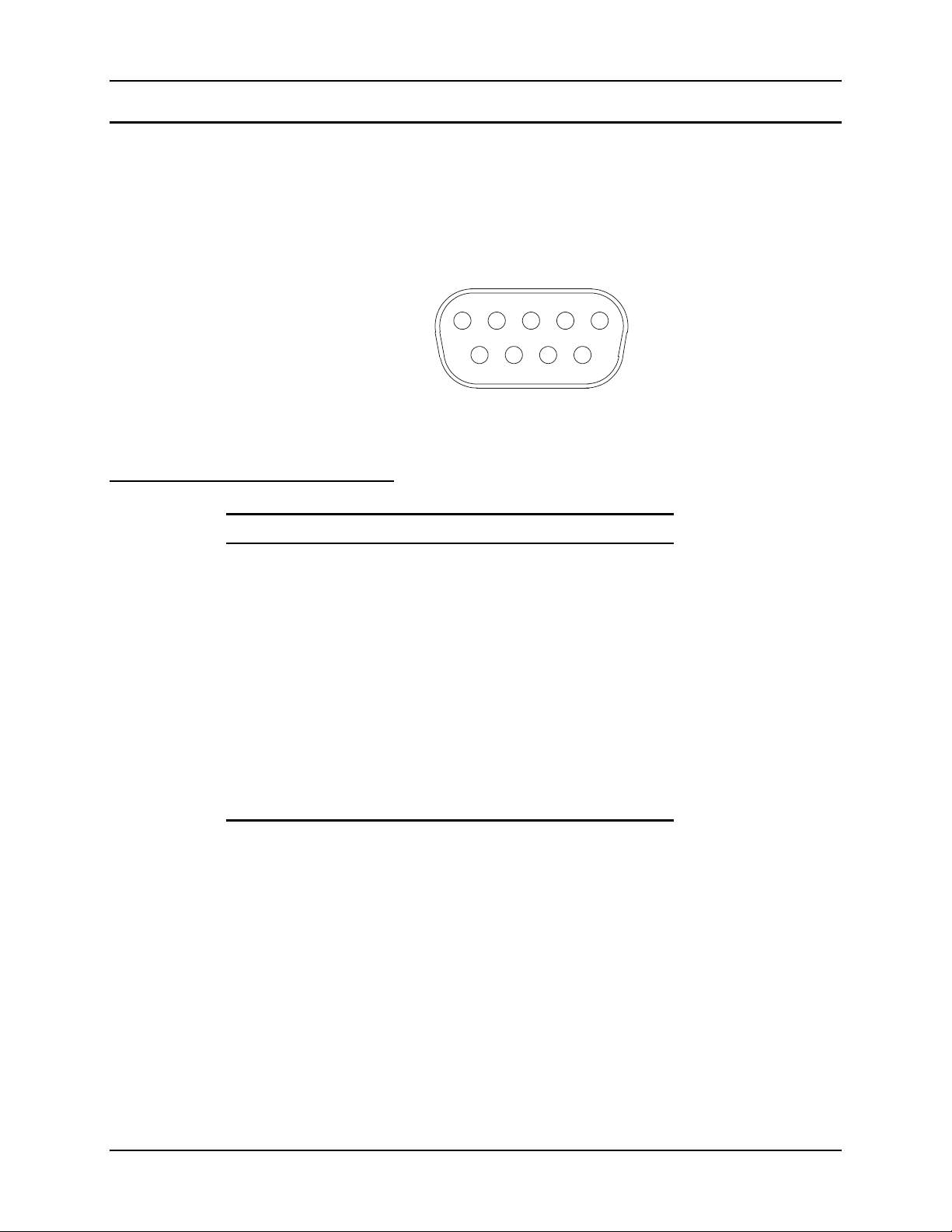
Keyboard/Mouse Connector
The VX5 external keyboard connector accepts:
• An LXE VMT keyboard with integrated pointing device
• An LXE VMT keyboard without integrated pointing device
• A dongle cable providing PS/2 connections for a standard PS/2 keyboard and mouse.
Pinout
5
9
3
421
876
Figure 2-5 VX5 Keyboard Connector and External Keyboard Cable Connector
The +5V supply available from the connector is current limited at 400mA.
Pin Signal Description
1 KBDAT_A Keyboard Data
2 MSDAT_A Mouse Data
3 – Not Connected
4 MSCLK_A Mouse Clock
5 DGND System Ground
6 – Not Connected
7 KBCLK_A Keyboard Clock
8 /BL_ENABLE Keyboard Backlight Enable
9 KDB_PWR Keyboard Power, 5V
Shell CGND Chassis Ground
E-EQ-VX5RG-A VX5 Reference Guide
Page 32
22 External Connectors
PS/2 Keyboard/Mouse Dongle Cable
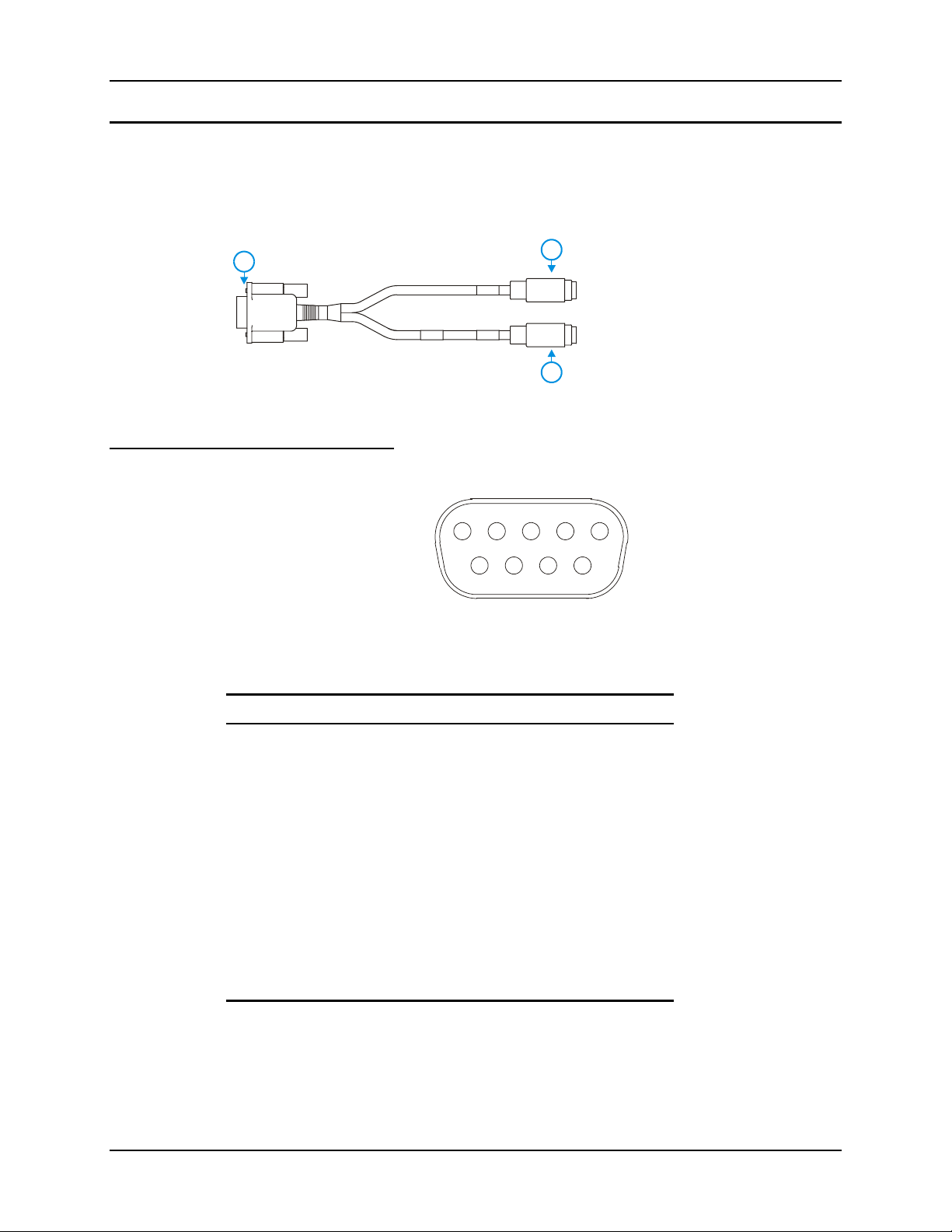
The PS/2 keyboard/mouse dongle cable allows a standard PS/2 keyboard and/or mouse to be
attached to the VX5. The PS/2 connectors on the dongle cable are labeled for keyboard and
mouse.
1
D9 Male Connector
Pinout
2
1 D9 Connector
2 PS/2 Keyboard Connector
3 PS/2 Mouse Connector
3
Figure 2-6 VX5 PS/2 Keyboard/Mouse Dongle Cable
3
876
5
421
9
Figure 2-7 D9 Male Connector
Pin Signal Description
1 KBDAT_A Keyboard Data
2 MSDAT_A Mouse Data
3 – Not Connected
4 MSCLK_A Mouse Clock
5 DGND System Ground
6 – Not Connected
7 KBCLK_A Keyboard Clock
8 /BL_ENABLE Keyboard Backlight Enable
9 KB_PWR Keyboard Power, 5V
Shell CGND Chassis Ground
VX5 Reference Guide E-EQ-VX5RG-A
Page 33

External Connectors 23
3
3
PS/2 Keyboard Connector
Pinout
PS/2 Mouse
5
6
Figure 2-8 PS/2 Keyboard Connector
Pin Signal Description
1 KBDAT_A Keyboard Data
2 – Not Connected
3 DGND System Ground
4 KBD_PWR Keyboard Power, 5V
5 KBCLK_A Keyboard Clock
6 – Not Connected
Shell CGND Chassis Ground
1
2
4
Pinout
5
6
Figure 2-9 PS/2 Mouse Connector
Pin Signal Description
1 MSDAT_A Mouse Data
2 – Not Connected
3 DGND System Ground
4 KBD_PWR Keyboard Power, 5V
5 MSCLK_A Mouse Clock
6 – Not Connected
Shell CGND Chassis Ground
1
2
4
E-EQ-VX5RG-A VX5 Reference Guide
Page 34
24 External Connectors
Ethernet/USB Connector
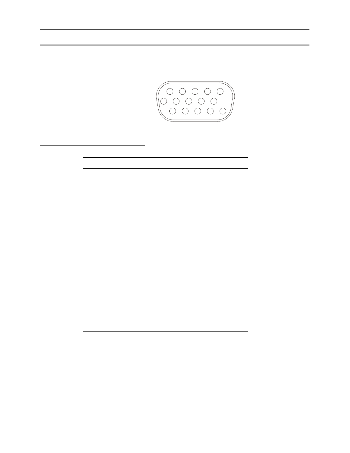
The VX5 Ethernet/USB connector accepts a dongle cable that provides a USB port and an
Ethernet port. The connector is shown below.
5
421
81591076
Pinout
11312
13
14
Figure 2-10 VX5 USB Connector and External USB Adapter Cable Connector
Pin Signal Description
1 USB2N_A USB D –
2 – Not Connected
3 – Not Connected
4 RXP Receive +
5 RXN Receive –
6 USB2P_A USB D +
7 DGND USB Power Return
8 – Not Connected
9 RJ45_45 RJ45, Pins 4 and 5 Connections
10 RJ45_78 RJ45, Pins 7 and 8 Connections
11 5V_USB_23 USB Power, Current Limited
12 – Not Connected
13 – Not Connected
14 TXN Transmit –
15 TXP Transmit +
Shell CGND Chassis Ground
VX5 Reference Guide E-EQ-VX5RG-A
Page 35
External Connectors 25
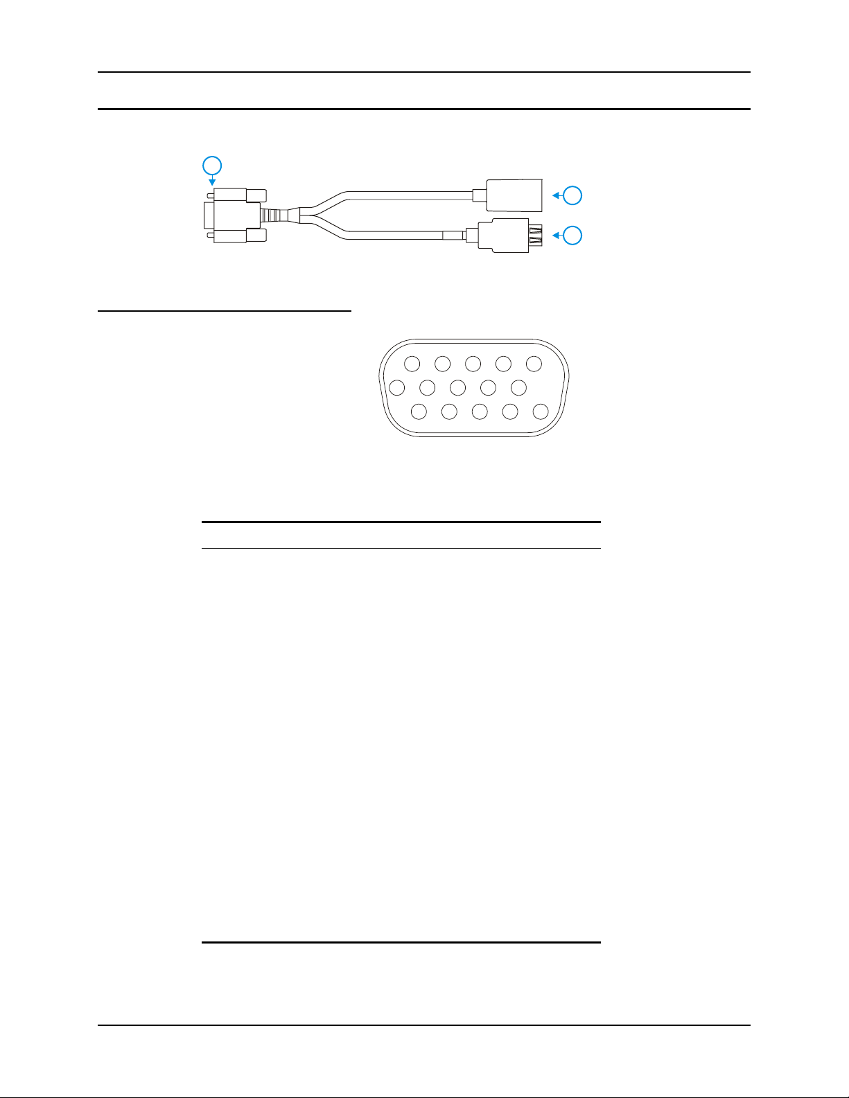
Ethernet/USB Dongle Cable
1
D15 Female Connector
Pinout
Pin Signal Description
1 USB2N_A USB D –
1 D15 Connector
2
2 RJ45 Connector
3
3 USB Connector
Figure 2-11 VX5 Ethernet/USB Dongle Cable
5
910 7 6
15
3
421
8
14
13
12
11
Figure 2-12 D15 Female Connector
2 – Not Connected
3 – Not Connected
4 RXP Receive +
5 RXN Receive –
6 USB2P_A USB D +
7 DGND USB Power Return
8 – Not Connected
9 RJ45_45 RJ45, Pins 4 and 5 Connections
10 RJ45_78 RJ45, Pins 7 and 8 Connections
11 5V_USB_23 USB Power, Current Limited
12 – Not Connected
13 – Not Connected
14 TXN Transmit –
15 TXP Transmit +
Shell CGND Chassis Ground
E-EQ-VX5RG-A VX5 Reference Guide
Page 36
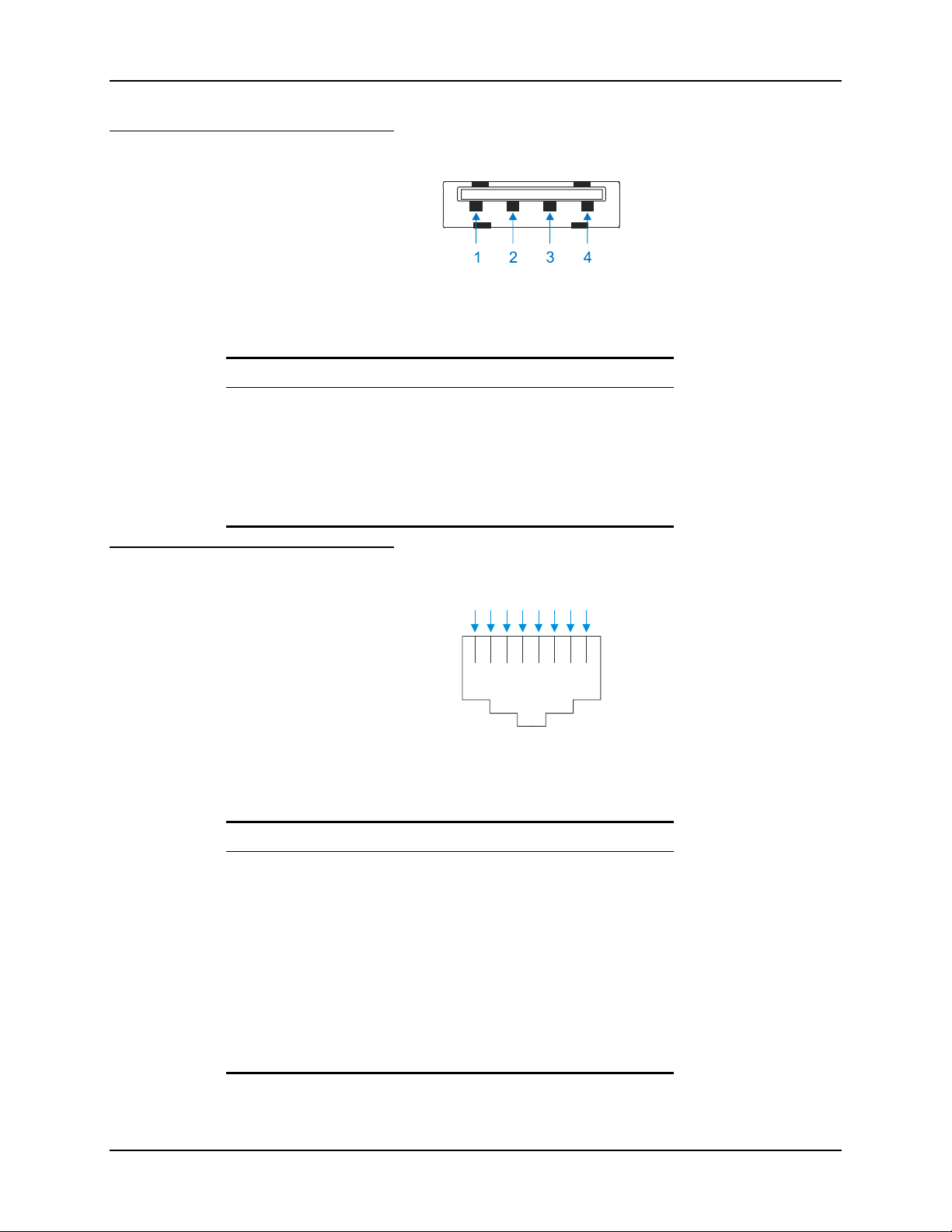
26 External Connectors
USB Connector
Figure 2-13 Dongle Cable USB Port
Pinout
Pin Signal Description
1 5V_USB_23 USB Power, Current Limited
2 USB2N_A USD D –
3 USB2P_A USB D +
4 DGND USB Power Return
Shell CGND Chassis Ground
RJ45 Connector
Pinout
1234
Figure 2-14 Dongle Cable Ethernet Port
Pin Signal Description
1 TXP Transmit +
2 TXN Transmit –
3 RXP Receive +
4 – Not Connected
5 – Not Connected
6 RXN Receive –
5678
7 – Not Connected
8 – Not Connected
VX5 Reference Guide E-EQ-VX5RG-A
Page 37
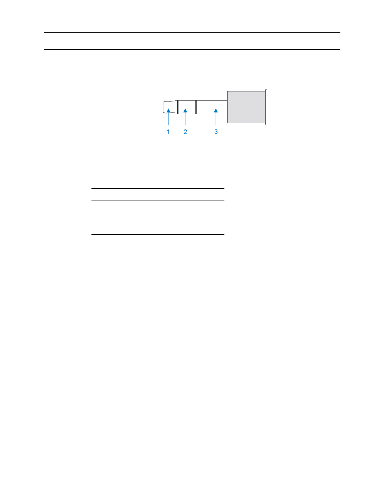
External Connectors 27
Audio Connector
The VX5 audio connector accepts a headset with a 2.5mm plug, such as a mono telephone headset
with microphone.
Figure 2-15 VX5 Audio Jack for External Speaker or Headphones
Note: The VX5 is not configured for standard PC speakers.
Pinout
Pin Description
1 Microphone (Not connected in VX5)
2 Speaker
3 Ground
E-EQ-VX5RG-A VX5 Reference Guide
Page 38
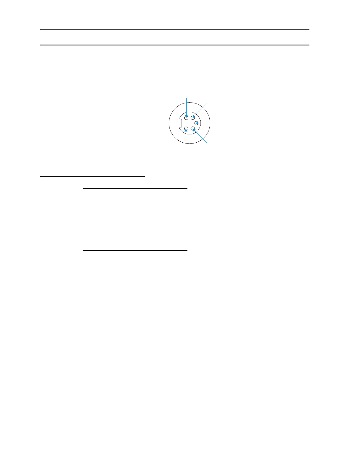
28 External Connectors
3
5
Power Supply Connector
Power is supplied to the VX5 through the power connector. Additionally this assembly provides a
connection point for the vehicle’s chassis ground to be connected internally to the conductive
chassis of the computer.
The VX5 internal power supply can accept DC input voltages in the range of 12 to 80 Volts.
1
2
4
Figure 2-16 The Power Connector
Pinout
Pin Signal
1 DC Positive (+)
2 UPS Battery Positive (+)
3 Chassis Ground
4 UPS Battery Negative (–)
5 DC Negative (–)
VX5 Reference Guide E-EQ-VX5RG-A
Page 39
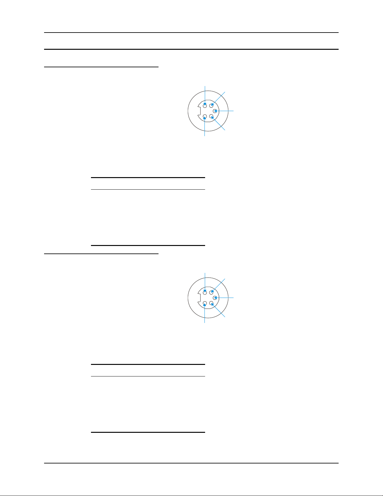
External Connectors 29
1
3
1
3
UPS Battery Pack Connectors
Input
2
4
5
Figure 2-17 The UPS Battery Pack Input Connector
Pinout
Pin Signal
1 DC Positive (+)
2 Not used
Output
Pinout
3 Chassis Ground
4 Not used
5 DC Negative (–)
5
Figure 2-18 The UPS Battery Pack Output Connector
Pin Signal
1 DC Positive (+)
2 UPS Battery Positive (+)
2
4
3 Chassis Ground
4 UPS Battery Negative (–)
5 DC Negative (–)
E-EQ-VX5RG-A VX5 Reference Guide
Page 40
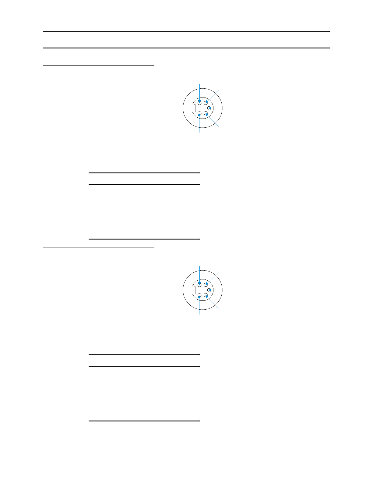
30 External Connectors
1
3
1
3
UPS Battery Extension Cable Connectors
Input
2
4
5
Figure 2-19 The UPS Battery Extension Cable Input Connector
Pinout
Pin Signal
1 DC Positive (+)
2 UPS Battery Positive (+)
Output
Pinout
3 Chassis Ground
4 UPS Battery Negative (–)
5 DC Negative (–)
5
Figure 2-20 The UPS Battery Extension Cable Output Connector
Pin Signal
1 DC Positive (+)
2 UPS Battery Positive (+)
2
4
3 Chassis Ground
4 UPS Battery Negative (–)
5 DC Negative (–)
VX5 Reference Guide E-EQ-VX5RG-A
Page 41
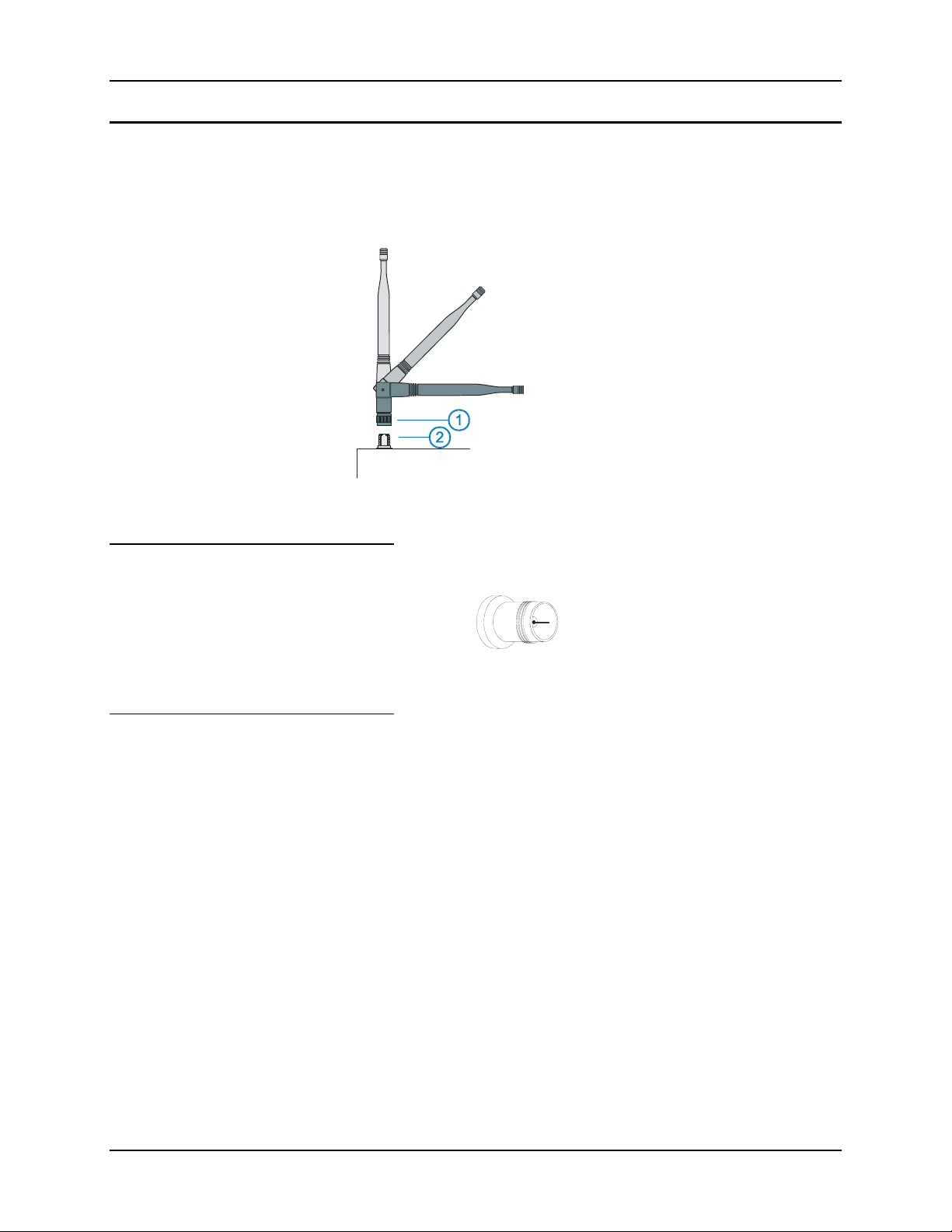
External Connectors 31
Antenna Connector
Note: VX5’s equipped with a radio require an external antenna. A VX5 without a radio does
not use an antenna. Some VX5’s may be equipped with a dual antenna option. For these
VX5’s, an external antenna must be connected to each antenna connector.
1. Antenna
2. Antenna Connector
Figure 2-21 2.4GHz Antennas
Spread Spectrum RF Antenna Connector Pin
Vehicle Remote Antenna Mount
The external antenna (or antennas) can be remotely mounted on the vehicle. Please refer to the
“Vehicle Remote Mount Antenna Installation Sheet” for details.
Figure 2-22 RF Antenna SS Connector
E-EQ-VX5RG-A VX5 Reference Guide
Page 42
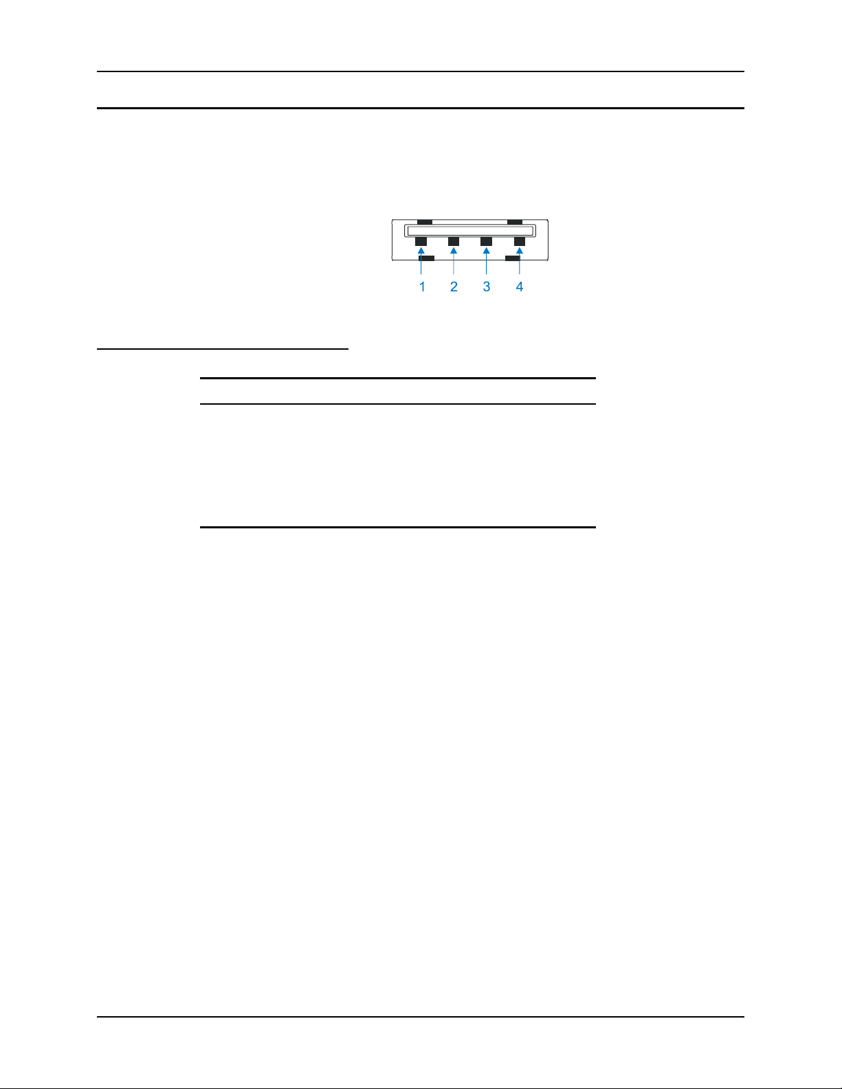
32 External Connectors
Internal USB Port
An internal USB port can be accessed by removing the access panel cover. This port conforms to
USB 1.0 specifications.
Figure 2-23 Dongle Cable USB Port
Pinout
Pin Signal Description
1 5V_USB_23 USB Power, Current Limited
2 USB2N_A USD D –
3 USB2P_A USB D +
4 DGND USB Power Return
Shell CGND Chassis Ground
VX5 Reference Guide E-EQ-VX5RG-A
Page 43
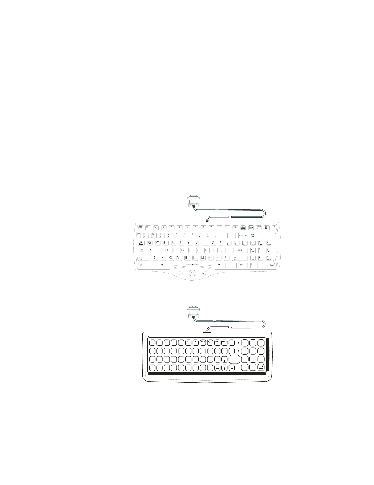
The Keyboards 33
The Keyboards
The following keyboard options are available for the VX5:
The LXE VMT keyboards are customized rugged keyboards, connected to the VX5 via a
watertight connector. The keyboards are available in the following configurations:
• LXE VMT 95-key QWERTY keyboard with integrated pointing device – a
customized rugged keyboard connected to the VX5 via a watertight connector.
• LXE VMT 60-key QWERTY keyboard – a customized rugged keyboard connected
to the VX5 via a watertight connector
• A standard PS/2 keyboard via an adapter cable attached to the “Keyboard/MOUSE”
port on the VX5. The adapter cable also provides a connector for a PS/2 mouse.
• A software keyboard, or virtual keyboard, can be displayed on the touch screen. The
virtual keyboard can be used in place of, or in addition to, a physical keyboard.
For more details on each keyboard type, please refer to the appropriate section later in this
chapter.
95 key with Integrated Pointing Device
ESC 2ND
CTRL
SHIFT
ALT SP
BREAK
R/S
CAPS
F2
F1
F3 F4 F5 F6
@
!
Q
W
|
\
S
A
%
#
E
R$T
'
;
"
:
G
F
D
H
~
CVXZ
B
F8
F7
(P)
*
&Y^
U
I
O
.
?
’
L
J
K
_
Home
´
N
M
F9
PgUp
PgDn END
BKLT
F10
INS
BKSP
ENTER
CAPS
/
7
2nd
=
4
123
<
0
-+
8
9
}{
5
6
]>[
DEL
.
60 key
Figure 2-24 The LXE VMT Keyboards with Cable
E-EQ-VX5RG-A VX5 Reference Guide
Page 44
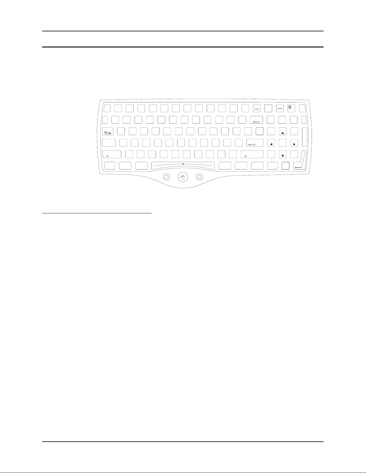
34 The Keyboards
_
/
The 95-key QWERTY Keyboard with Pointing Device
Designed for ease of use with Windows operating systems, the 95-key keyboard with pointing
device connects via a cable to the keyboard port on the VX5. Additional Windows keys (the
Windows log key and the Application key) and an integrated pointing device are provided for
ease of use with Windows operating systems.
Key Maps
~
`
Caps
Lock
Esc
Tab
Shift
Ctrl
F2 F3 F4 F5 F6 F7 F8 F9 F10 F11 F12F1
^
1!2
3#@4$5%6
&
7
Q W E R T UY IO
A S D F G JHK
Z X C V BMN
Alt
Print
Screen
SysRq
*
8
RL
)
(
0
9
L
>
<
.
,
+
-
P
:
;
?
BackSpace
=
}
{
[
"
'
Shift
|
]
\
Enter
CtrlAlt
Scroll
Lock
Num
Lock
7
Home
4
1
End
Ins0Del
Pause
Break
/*
8
9
PgUp
5
6
2
3
PgDn
.
Fn
=
+
Enter
Figure 2-25 The 95-key QWERTY Keyboard
The 95-key keyboard supports all 104 keyboard functions (101 keyboard standard plus Windows
keys) and includes an integrated pointing device and left and right mouse buttons. However,
because the keyboard only has 95 keys, all functions are not visible (or printed on the keyboard).
Therefore the VX5 keyboard supports what is called hidden keys -- keys that are accessible but
not visible on the keyboard.
As with a standard keyboard, many keys are found in the Alphanumeric section as well as on the
Numeric keypad (i.e. the 1 key is found on the numeric keypad and above the alpha characters on
standard keyboards). However these keys send distinctly different scan codes when the keys are
pressed. The hidden keys supported by the VX5 are listed in Appendix A, "Key Maps".
nd
Note: The 95-key keyboard does not have a 2
key function.
NumLock and the VX5
For the 95-key keyboard, the NumLock key and the numeric keys are backlit green when
NumLock is off. When NumLock is on, the backlight for the NumLock key and the numeric keys
are amber.
CapsLock, Scroll Lock and the VX5
For the 95-key keyboard, the CapsLock key is backlit green when CapsLock is off. When
CapsLock is on, the backlight for the CapsLock key is amber.
The Scroll Lock key is backlit green when Scroll Lock is off. When Scroll Lock is on, the
backlight for the Scroll Lock key is amber.
The default values for CapsLock and Scroll Lock are Off.
VX5 Reference Guide E-EQ-VX5RG-A
Page 45

The Keyboards 35
Keyboard Backlight
The 95-key keyboard backlights each key with an LED. The keyboard backlight is
manually controlled using the “backlight” key in the upper right hand corner of the
keyboard. Pressing the backlight key cycles the keyboard backlight through the levels of
backlight intensity:
• Off
• Maximum intensity
• Medium intensity
• Low intensity.
E-EQ-VX5RG-A VX5 Reference Guide
Page 46
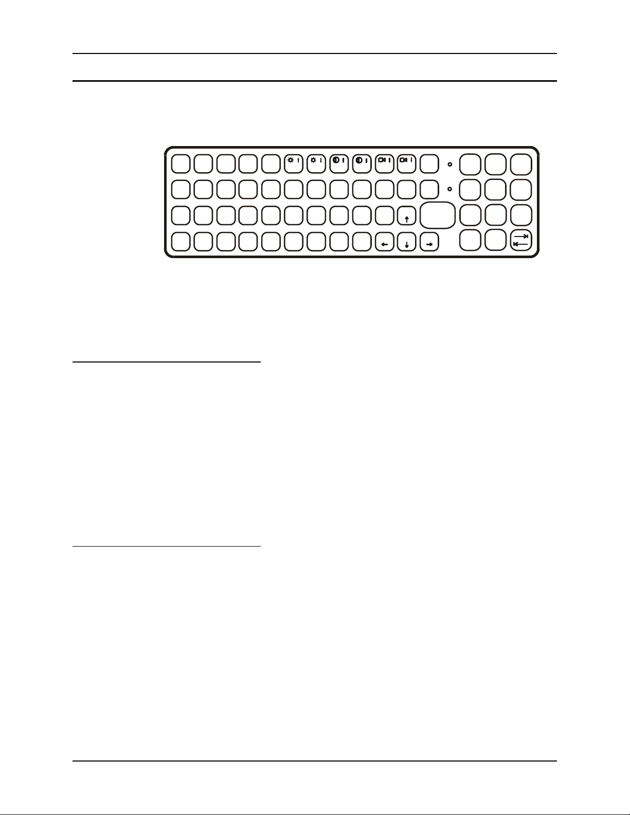
36 The Keyboards
The 60-key QWERTY Keyboard
The 60-key keyboard has 101 keyboard functions, including a numeric keyboard pad. Please refer
to Appendix A, "Key Maps", for keypress combinations.
Key Maps
ESC
CTRL
SHIFT
ALT SP
2ND
!
|
Q
A
BREAK
CAPS
F1 F2 F3
@
#
E
W
\
:
S
D
R/S
R$T
;
F
CVXZ
F4 F5
%
"
G
F6
F7
*
&
^
U
Y
'
H
~
´
B
I
.
’
J
K
_
N
M
F8
(
?
Home
O
L
F9
)
P
PgUp
PgDn END
BKLT
F10
INS
BKSP
ENTER
CAPS
/
7
2nd
=
4
123
<
0
-+
8
9
}{
5
6
]>[
DEL
.
Figure 2-26 The 60-key QWERTY Keyboard
Note: When the 60-key keyboard is used, the touchscreen MUST BE configured to recognize
holding the <Ctrl> key then touching the screen as a right click. Please refer to
“Configuring Right Click on the Touchscreen” in Chapter 4, “Configuration” for more
details.
The 60-key keyboard supports all 101 keyboard functions. However, because the keyboard only
has 60 keys, all functions are not visible (or printed on the keyboard). Therefore the VX5
keyboard supports what is called hidden keys -- keys that are accessible but not visible on the
keyboard.
On standard keyboards many keys are found in the Alphanumeric section as well as on the
Numeric keypad (i.e. the 1 key is found on the numeric keypad and above the alpha characters on
standard keyboards). However these keys send distinctly different scan codes when the keys are
pressed. The default codes for the VX5 number keys correspond to the numeric keypad on
standard keyboards. In order to duplicate the codes sent when the alphanumeric key is pressed, the
hidden keystroke must be used.
The hidden keys supported by the VX5 are listed in Appendix A, "Key Maps".
Unused Key Functions
There are several key functions on the 60-key keyboard that are not used on the VX5. These
include:
• <2nd> <F3> – The Resume/Suspend function is not used as Microsoft Windows controls
all power management modes.
nd
• <2
> <F4> and <2nd> <F5> – The Display Brightness functions are not used as the
display brightness is adjusted by the buttons on the VX5 control panel.
• <2nd> <F6> and <2nd> <F7> – The Contrast functions are not used as the contrast is not
adjustable on the TFT display on the VX5.
• <2nd> <F8> and <2nd> <F9> – The Volume control keys are not used as volume is
adjusted via the Microsoft Windows Volume icon in the System Tray.
VX5 Reference Guide E-EQ-VX5RG-A
Page 47
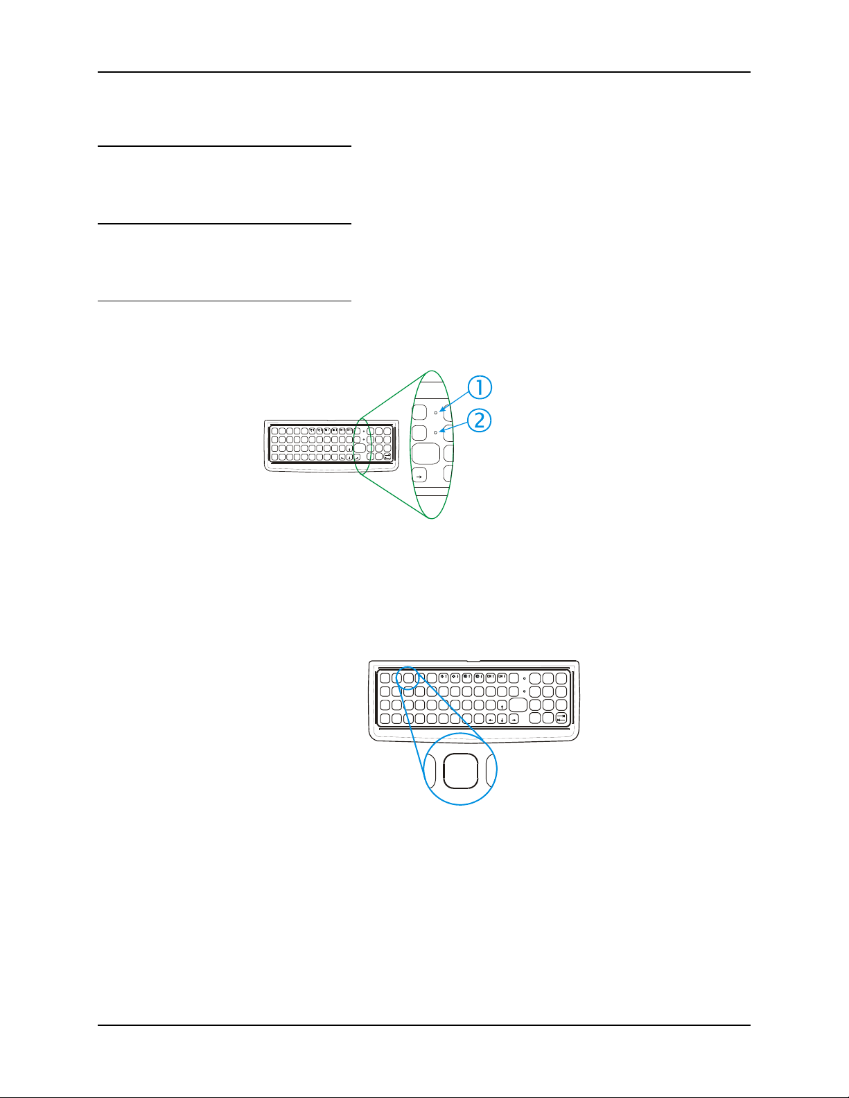
The Keyboards 37
• <2nd> <F10> – Please see “Keyboard Backlight” later in this section for details on
toggling the keyboard backlight.
NumLock and the VX5
The 60-key keyboard does not have a NumLock indicator or key. NumLock can be toggled On
or Off using the <2
Keyboard Backlight
The LXE keyboard keys are backlit with LEDs. The backlight is manually controlled using the
nd
> + <CTRL> + <F10> keypress sequence.
<2
Keyboard LEDs
The VX5 keyboard has three (2) LED indicators.
BREAK
CAPS
ESC 2ND
F1F2F3 F4 F5 F6 F7 F8
@
#
!
CTRL
E
Q
W
|
\
:
SHIFT
D;F
S
A
ALT SP
nd
> <SHIFT> <F10> keypress sequence.
CAPS
BKLT
/
R/S BKLT
R$T
CVXZ
F9
(P)
*
%U&Y^
I
O
PgUp
.
'
?
’
"
G
K
L
J
H
Home
PgDn END
~
´
B
CAPS
/
F10
2nd
INS
=
BKSP
456
ENTER
123
<
0M_N
-+
]>[
DEL
.
F10
2nd
INS
BKSP
ENTER
END
=
[
<
987
}{
Figure 2-27 Keyboard LEDs
1. CapsLock Mode
LED Indicator
2. Secondary Mode
LED Indicator
CAPS LED
This LED indicates the state of the keyboard CapsLock mode. If CapsLock is enabled this LED is
illuminated green. When CapsLock is off, the LED is dark.
BREAK
R/S
CAPS
ESC 2ND
F1 F2 F3F4F5 F6F7F8
@
!
#
CTRL
E
Q
W
|
\
:
SHIFT
D;F
S
A
ALT SP
D
R$T
CVXZ
%U&Y^
"
G
CAPS
'H.
’
~
´
B
F1
*
J
_
N
CAPS
BKLT
/
F10
INS
BKSP
ENTER
2nd
=}{
456
123
<
0
-+
]>[
DEL
.
987
F9
(P)
I
O
PgUp
?
L
K
Home
PgDn END
M
B
Figure 2-28 The CapsLock Key
nd
Press <2
> then <F1> to toggle CapsLock On and Off.
The default value of CapsLock is “Off”.
E-EQ-VX5RG-A VX5 Reference Guide
Page 48
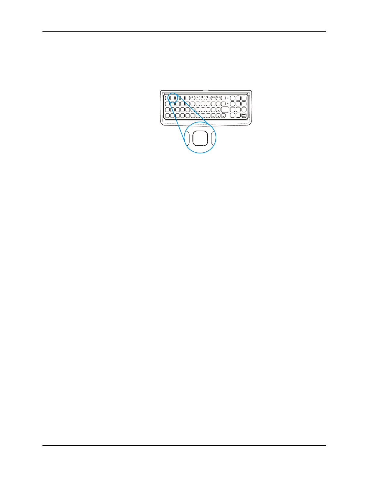
38 The Keyboards
Secondary Keys LED
The VMT keyboard is equipped with several secondary keys. These keys are identified by the
superscripted text found on the keyboard keys. The secondary keys are accessible by using two
(2) keystrokes: the <2
nd
> key followed by the superscripted key.
Once the <2
illuminated and the <2
with a <2
nd
> state is enabled (by pressing the <2nd> key) the Secondary Mode LED is
nd
> keypress and then immediately off with another <2nd> keypress.
For example:
Press <2
Press <2
Press <2
Press <2
nd
> and <F1> to turn CapsLock on and off.
nd
> and <↑> to initiate the PgUp command.
nd
> and <Q> to type the “!” key.
nd
> and <BkSp> to enter the Insert (Ins) mode.
ESC 2ND
CTRL
SHIFT
ALT SP
!
Q
|
A
BREAK
CAPS
F1 F2 F3
@
#
W
\
:
S
E
D
R/S
F4 F5F6F7
*
%U&Y^
R$T
'
’
;
"
G
F
J
H.K
_
~
´
CVXZ
B
N
C2ND
CAPS
BKLT
/
F10
INS
BKSP
ENTER
2nd
=
456
123
<
0
-+
}{
]>[
DEL
.
987
F9
F8
(P)
I
O
PgUp
?
L
Home
PgDn END
M
C
Figure 2-29 The Secondary Key
nd
> state is enabled until another key is pressed. The <2nd> key is toggled on
VX5 Reference Guide E-EQ-VX5RG-A
Page 49
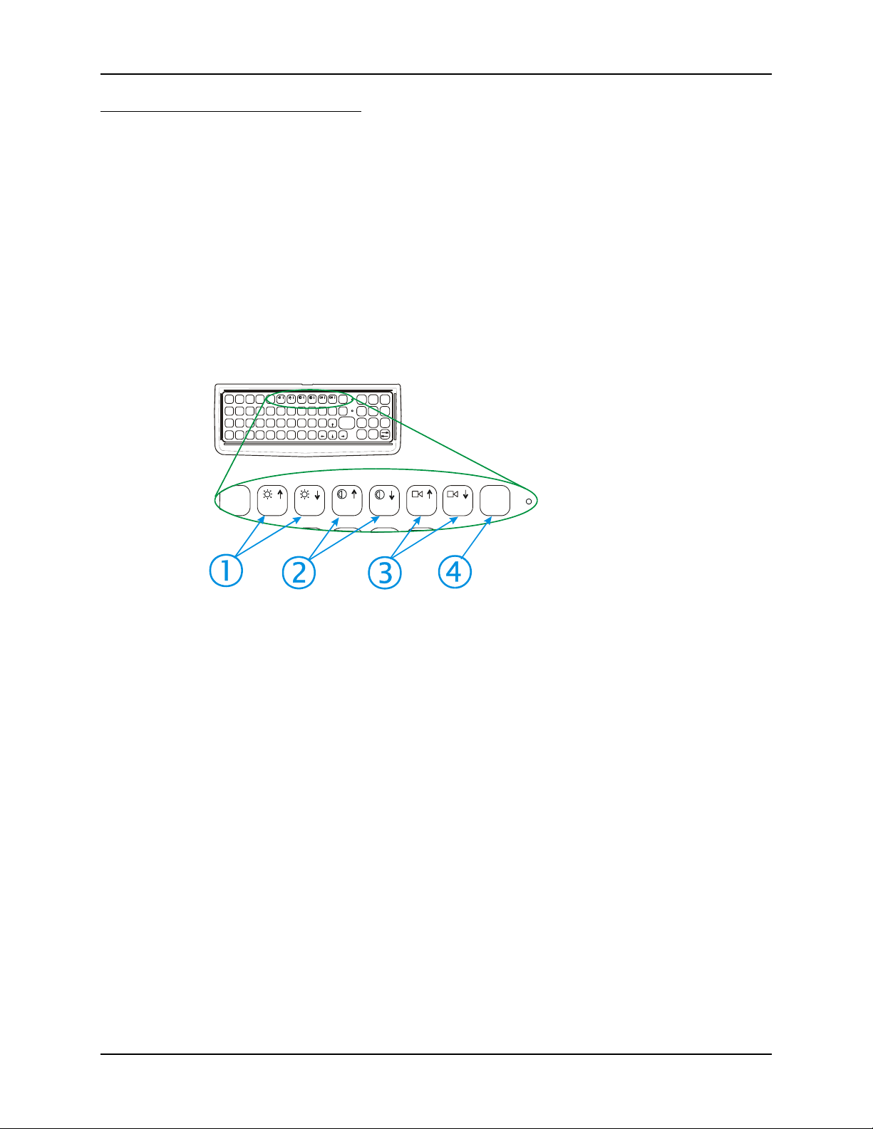
The Keyboards 39
Control Keys
The VMT keyboard has several control keys. Because of the construction of the VX5 and the
Microsoft Windows operating system, many of the Control Keys are not used on the VX5.
nd
Note: The 2
The 2
The <F10> key is used to toggle the backlight as part of the keypress sequence <2
+ <F10>. This key sequence immediately toggles the status of the keyboard backlight. Pressing
nd
> + <F10> has no effect on the keyboard backlight.
<2
functions of the <F4> and <F5>keys are not used as the display brightness is
adjusted via the buttons on the control panel.
nd
functions of the <F6>, and <F7> keys are not used as the VX5 has TFT LCD
The 2
screen with no provision for contrast adjustments.
nd
functions of the <F8> and <F9> keys are not used as the sound volume on the
VX5 is controlled with the Sound icon in the Microsoft Windows System Tray.
nd
> + <CTRL>
ESC 2 ND
CTRL
SHIFT
ALT SP
!
|
Q@W
A
BREAK
CAPS
F1 F2 F3
#
\
:
S
E
D
R/S
%U&Y^
R$T
;
"
F
F4 F5F6F7
'H.
’
G
J
~
´
BCVXZ
N
CAPS
BKLT
/
-+
F9 F10
F8
(P)
*
INS
I
O
BKSP
PgUp
?
ENTER
L
K
_
Home
PgDn E ND
M
2nd
=
456
123
<
0
987
}{
]>[
DEL
.
1. Display Brightness Control
Keys (Not used)
2. Display Contrast Control
Keys (Not used)
R/S
F3
F6
F5
F4
F8
F7
BKLT
F9
F10
3. Speaker Volume Control
Keys (Not used)
4. Backlight Control Key
(See above)
Figure 2-30 The VMT Keyboard Display Controls
E-EQ-VX5RG-A VX5 Reference Guide
Page 50

40 The Keyboards
General Windows Keyboard Shortcuts
Use the keyboard shortcuts in the chart below to navigate with any VX5 keyboard. These are
standard keyboard shortcuts for Windows applications.
Press these keys … To …
CTRL + C Copy
CTRL + X Cut
CTRL + V Paste
CTRL + Z Undo
DELETE Delete
SHIFT with any of the arrow keys
CTRL+A Select all.
ALT+ESC Cycle through items in the order they were opened.
CTRL+ESC Display the Start menu.
ALT+Underlined letter in a menu
name
Underlined letter in a command
name on an open menu
ESC Cancel the current task.
Select more than one item in a window or on the
desktop, or select text within a document.
Display the corresponding menu.
Carry out the corresponding command.
VX5 Reference Guide E-EQ-VX5RG-A
Page 51
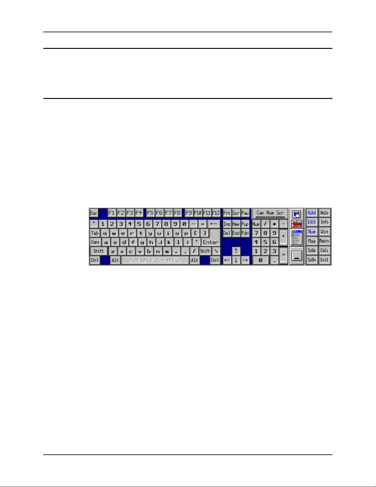
The Keyboards 41
PS/2 Keyboard/Mouse
A standard PS/2 keyboard and mouse can be attached to the VX5 using the appropriate dongle
cable. The dongle cable attaches to the VX5 and provides two PS/2 connectors, one labeled
“Keyboard” and one labeled “Mouse”. Please refer to documentation provided with the PS/2
keyboard and mouse for more information on their operation.
Virtual Keyboard
The optional My-T-Soft software provides a virtual keyboard on the touchscreen. To start the
virtual keyboard, click on the My-T-Soft icon on the desktop or select Start|Programs|My-T-
Soft|My-T-Soft.
The virtual keyboard provides several configuration options, including:
• Keyboard size
• QWERTY vs. ABCD
• Standard 101 key format vs. Windows 104 key format
For more information on configuring the virtual keyboard, click on Start|Programs|My-TSoft|My-T-Soft Setup.
Figure 2-31 Virtual Keyboard, Typical Configuration
Virtual keyboards display the actual character the keypress outputs. For example, pressing the
<Shift> key on the virtual keyboard toggles the characters displayed on the keys between upper
and lower case.
Note: When the virtual keyboard is displayed, the physical keyboard is still active, if attached.
Therefore it is possible to input data from both keyboards.
E-EQ-VX5RG-A VX5 Reference Guide
Page 52
42 The Display
The Display
The VX5 Display is a thin-film transistor display capable of supporting SVGA graphics modes.
Display size is 800 x 600 pixels. The display covering is designed to resist stains. The touch
screen allows signature capture and touch input.
Cleaning the Display
Keep fingers and rough or sharp objects away from the display. If the glass becomes soiled or
smudged, clean only with a standard household cleaner such as Windex® without vinegar or use
Isopropyl Alcohol. Do not use paper towels or harsh-chemical-based cleaning fluids since they
may result in damage to the glass surface. Use a clean, damp, lint-free cloth. Do not scrub optical
surfaces. If possible, clean only those areas which are soiled. Lint/particulates can be removed
with clean, filtered canned air.
Touchscreen
The touch screen is a Resistive Panel with a scratch resistant finish that can detect touches by a
stylus, and translate them into computer commands. In effect, it simulates a computer mouse.
Only Delrin or plastic styluses should be used.
Note: Always use the point of the stylus for tapping or making strokes on the display. Never use
an actual pen, pencil or sharp object to write on the touch screen.
An extra or replacement stylus may be ordered from LXE. See the "Accessories" section for the
stylus part number.
Please refer to Chapter 4, “System Configuration” for more information on:
• Calibrating the touchscreen
• Disabling the touchscreen.
LXE offers a replaceable touchscreen protective film to protect the touchscreen when the VX5 is
used in an abrasive environment. For information on installing or removing the protective film,
please refer to the “VX5 User’s Guide”.
Factory Default Settings
Boot Sequence
(devices searched in this order)
Legacy Floppy (A and B) Disabled
Primary and Secondary Master and
Slave drives
Display POST Messages Disabled
Show Summary Screen Disabled
Power Supply ATX
Power Savings Disabled
Onboard LAN RPL BIOS Disabled
Removable Devices (i.e. USB floppy drive), Hard
Drive, CD-ROM Drive, Network Boot (i.e. PXE)
Auto
For more information on the default settings, please refer to Chapter 4, “System Configuration”.
VX5 Reference Guide E-EQ-VX5RG-A
Page 53
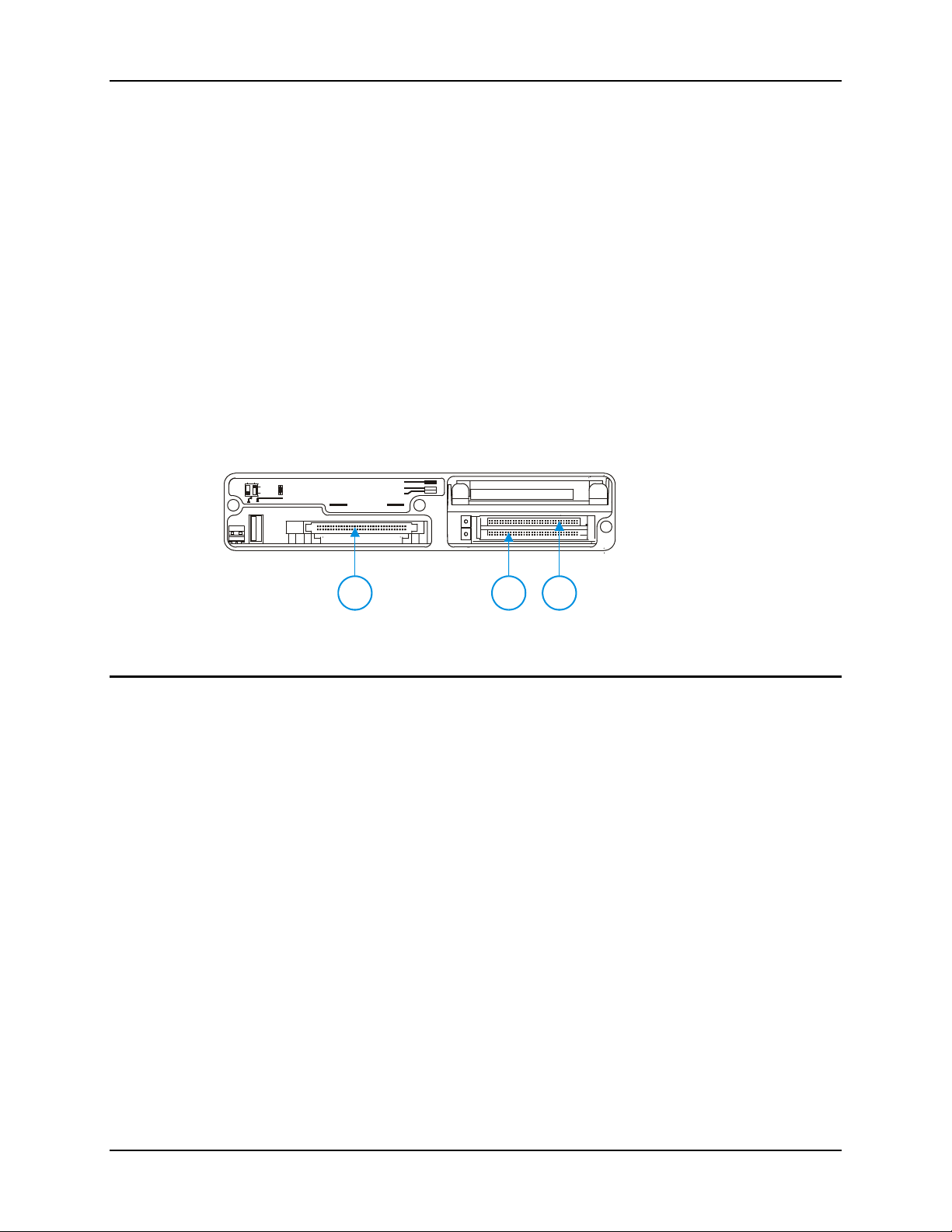
PCMCIA/CardBus and ATA Slots 43
PCMCIA/CardBus and ATA Slots
The VX5 has two PCMCIA/CardBus slots and one ATA slot. The PCMCIA slots are stacked on
top of each other and located on the right hand side of the opening. The ATA is located on the
left hand side of the opening.
The PCMCIA slots support the Personal Computer Memory Card International Association
(PCMCIA) 2.1 standards. The upper slot is designated as Slot 0 and the lower slot is designated
as Slot 1.
Slot 0 accepts Type I or II PCMCIA cards. If a radio card is used, it must be installed in Slot 0 to
prevent damage to the internal radio cables. LXE supports only Type II 2.4GHz Spread Spectrum
radios.
Slot 1 accepts Type I, II or III PCMCIA cards. A Type III card can be used only when no card is
installed in Slot 0.
The left slot is used for ATA memory cards, either PCMCIA or Compact Flash (CF) format via a
PCMCIA adapter. The left slot is connected to the secondary IDE interface.
PCMCIA Slots
Slot 0 and 1 PCMCIA Card Management is handled by Microsoft Windows. The PCMCIA cards
are Plug and Play devices and can be “hot swapped”. For more details, refer to the Windows help
screens or refer to the documentation delivered with the PCMCIA card.
COM1 COM2
SCANNER
SERIAL
IDE DRIVE
CARD BUS A
USB
CARD BUS B
PCMCIA/CF ATA
1. ATA PCMCIA Slot (Left)
2. Slot 1 (Lower Right)
3. Slot 0 (Upper Right)
21
3
Figure 2-32 The PCMCIA and ATA Slots
E-EQ-VX5RG-A VX5 Reference Guide
Page 54

44 PCMCIA/CardBus and ATA Slots
PCMCIA Pinout
Pin Signal Pin Signal
1 GND 35 12V_RF_POWER
2 D3 36 -CDI
3 D4 37 D11
4 D5 38 D12
5 D6 39 D13
6 D7 40 D14
7 -CE1 41 D15
8 A10 42 -CE2
9 -OE 43 n.c. or VS1#
10 A11 44 -IORD
11 A9 45 -IOWR
12 A8 46 A17
13 A13 47 A18
14 A14 48 A19
15 -WE 49 A20
16 RDY/-IREQ 50 A21
17 SLOT_VCC 51 SLOT_VCC
18 SLOT-VPP 52 SLOT_VPP
19 A16 53 A22
20 A15 54 A23
21 A12 55 A24
22 A7 56 A25
23 A6 57 n.c. or VS2#
24 A5 58 RESET
25 A4 59 -WAIT
26 A3 60 -INPACK
27 A2 61 -REG
28 A1 62 BVD2/-SPKR
29 A0 63 BDV1/-STSCHG
30 D0 64 D8
31 D1 65 D9
32 D2 66 D10
33 WP/A_-IOIS16 67 -CD2
34 GND 68 GND
VX5 Reference Guide E-EQ-VX5RG-A
Page 55
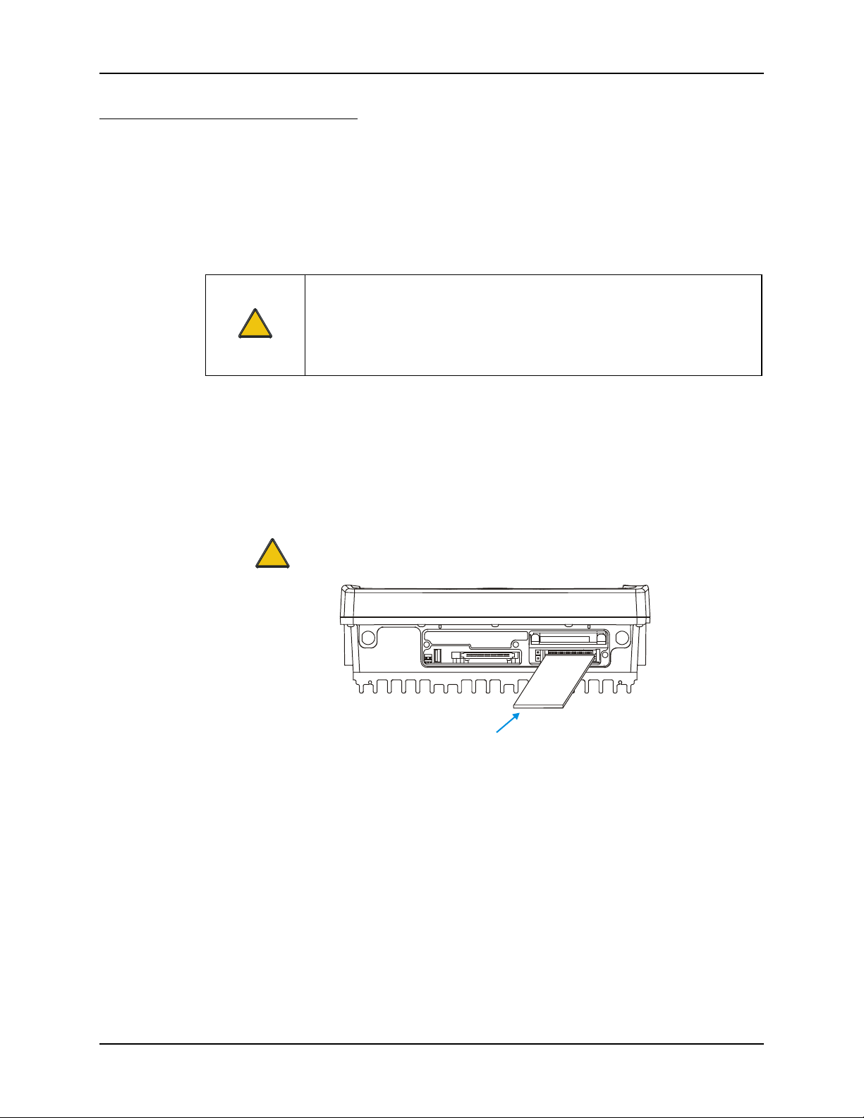
PCMCIA/CardBus and ATA Slots 45
d
Install PCMCIA Cards
Equipment Needed: Phillips No. 1 screwdriver and a Torque wrench capable of measuring to 9±1
inch pounds (1.016±.11 N/m).
Note: The example below details installing a 2.4GHz radio card. Installation of other
PCMCIA cards is similar, except there is no antenna.
Install the 2.4GHz Type II PCMCIA Radio
Caution
!
1. Turn the VX5 off and detach the power cable.
2. Loosen the three (3) Phillips head screws securing the access panel cover so the cover can
be removed. The screws are a captive part of the cover and cannot be removed.
Partially insert the 2.4GHz Type II PCMCIA Radio into Slot 0 (the upper right slot).
Caution
The LXE Model VX5 Vehicle Mount Computer is specifically for use with
LXE Model Numbers 480628-4096, 480824-3300 and LXE 6526 2.4GHz
Type II PCMCIA radios. Substitution of other PCMCIA radios will void the
FCC, Industry Canada and other international radio certifications for the
Model VX5 Vehicle Mount Computer and is strictly prohibited.
Slot 0 MUST BE used for the radio card. Installing a radio card in Slot 1 can
result in pinching or other damage to the internal antenna cable.
!
Radio Car
Figure 2-33 Inserting the 2.4GHz Type II PCMCIA Radio
Note: The tethered access panel cover is not shown in the illustration above.
E-EQ-VX5RG-A VX5 Reference Guide
Page 56
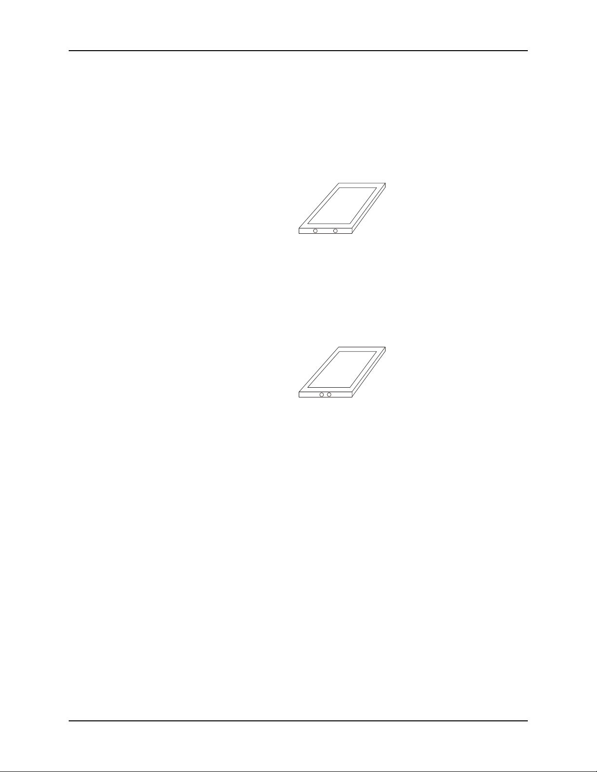
46 PCMCIA/CardBus and ATA Slots
3. Before completely inserting the 2.4GHz Radio, connect the Antenna Cable to the 2.4GHz
Radio, using the port(s) indicated below:
Cisco Radio Card
• Cisco radio with single antenna – Connect antenna cable to right port, as shown
below.
• Cisco radio with dual antennas – Connect antenna cables to both ports.
Figure 2-34 Cisco Antenna Cable Connections
Symbol 11Mb Radio Card
• Symbol 11Mb radio with single antenna – Connect antenna cable to left port, as
shown below.
• Symbol 11Mb radio with dual antennas – Connect antenna cables to both ports.
Figure 2-35 Symbol 11Mb Antenna Cable Connections
4. Now complete the insertion of the 2.4GHz Type II PCMCIA Radio into Slot 0 or Slot 1.
Note: When this process is complete, reattach the access cover screws using a torque
wrench capable of measuring to 9±1 inch pounds (1.016±.11 N/m). The screws
must be fastened to 9 inch pounds each. The screws require a Phillips size 1
driver head.
5. Re-connect the power cord/cable and turn the VX5 on.
VX5 Reference Guide E-EQ-VX5RG-A
Page 57
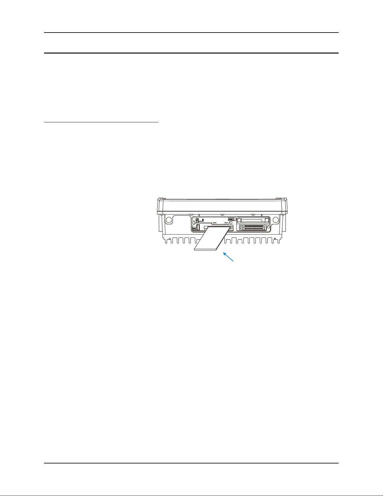
PCMCIA/CardBus and ATA Slots 47
A
d
ATA Slot
The ATA slot is connected to the secondary IDE controller. The slot accepts a PCMCIA card or a
compact flash card via a PCMCIA adapter. The VX5 must be powered down before inserting or
removing an ATA card.
Only ATA memory cards may be used in these slots. No other types of PCMCIA or compact
flash cards may be used in the ATA slots. The ATA slots do not provide for “hot swapping” of
cards.
Install an ATA Card
1. Turn the VX5 off and detach the power cable.
2. Loosen the three (3) Phillips head screws securing the access panel cover so the cover
can be removed. The screws are a captive part of the cover and cannot be removed.
3. Insert the card into the ATA slot. This slot accepts an ATA PCMCIA card or a compact
flash ATA card in a PCMCIA adapter.
COM1 COM2
SCANNER
SERIAL
USB
PCMCIA/CF ATA
CARD BUS A
CARD BUS B
IDE DRIVE
TA Car
Figure 2-36 Inserting the ATA Card
Note: The tethered access panel cover is not shown in the illustration above.
Note: When this process is complete, reattach the access cover screws using a torque
wrench capable of measuring to 9±1 inch pounds (1.016±.11 N/m). The screws
must be fastened to 9 inch pounds each. The screws require a Phillips size 1
driver head.
4. Re-connect the power cord/cable and turn the VX5 on.
5. Review the BIOS settings to ensure the ATA card is recognized as the secondary drive.
E-EQ-VX5RG-A VX5 Reference Guide
Page 58

48 PCMCIA/CardBus and ATA Slots
VX5 Reference Guide E-EQ-VX5RG-A
Page 59
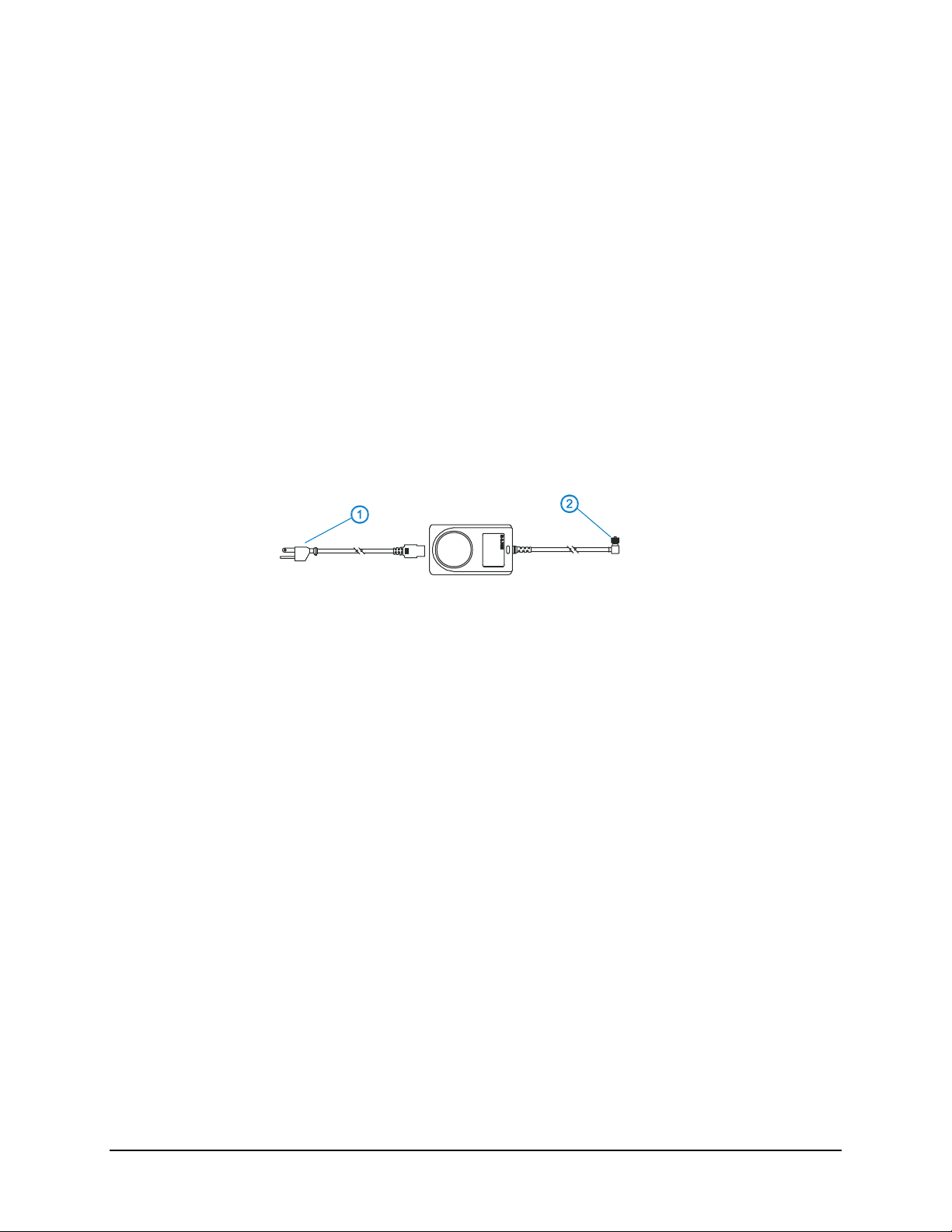
Introduction
AC to DC power input for the VX5 is delivered via an optional external power supply. See
“External Power Supply”.
Vehicle power input for the VX5 is 12V to 80V DC nominal and is accepted without the need to
perform any manual operation within the VX5. See “Vehicle 12-80VDC Direct Connection.” An
optional uninterruptible power supply (UPS) battery can be used with the vehicle DC power
supply.
Power input is fused for protection and the fuse is externally accessible on the VX5.
External Power Supply
Chapter 3 Power Supply
1. AC Input Cable
(US only)
2. DC Output Cable
Figure 3-1 Optional Power Supply Cable
In North America, this unit is intended for use with a UL Listed ITE power supply with
output rated 12 – 80 VDC, minimum 75 W. Outside North America, this unit is intended
for use with an IEC certified ITE power supply with output rated 12 – 80 VDC, minimum
75 W.
The external power supply may be connected to either a 120V, 60Hz supply or, outside North
America, to a 230V, 50Hz supply, using the appropriate detachable cordset. In all cases, connect
the external AC supply to a properly grounded source of supply provided with maximum 15 Amp
overcurrent protection (10 Amp for 230V circuits).
Note: Instructions for using this configuration are contained in “VX5 User’s Guide” section
titled “Installation”.
E-EQ-VX5RG-A VX5 Reference Guide
Page 60

50 External Power Supply
Specifications
Feature Specification
Dimensions 3.40” x 5.87” x 2.00”
Weight <3.0 pounds
Input Power Switch None
Power “ON” Indicator None
Input Fusing None
Input Voltage 90VAC min - 264VAC max
Input Frequency 47 - 63 Hz
Input Surge Current 50 Amps max @ 264VAC input
Input Connector Standard IEC input power cord
(included with US units only)
Output Connector 3 pin female connector
Output Voltage +24VDC
Output Voltage
Tolerance
Output Current 0 Amps min, 1.87 Amps max
Safety and Emissions
Compliance
+/- 8%, measured at the end of the output
power cable
FCC, Part 15, Radio Frequency Devices,
Class B.
EN 55022
UL1950 and IEC 950
VX5 Reference Guide E-EQ-VX5RG-A
Page 61
CMOS Battery 51
Environmental Specifications
The AC to DC adapter will withstand the following environmental characteristics:
Feature Specification
Operating Temperature see VX5 Environmental Specifications
Storage Temperature see VX5 Environmental Specifications
Humidity Operates in a relative humidity of:
5 – 95% (non-condensing)
ESD Immunity Per IEC 801-1
CMOS Battery
The LXE VX5 has a permanent 190 mAh Lithium battery installed to maintain time, date and
CMOS setup information. The lithium battery is not user serviceable and should last five years
with normal use before it requires replacement.
Note: This battery should only be changed by authorized service personnel.
E-EQ-VX5RG-A VX5 Reference Guide
Page 62
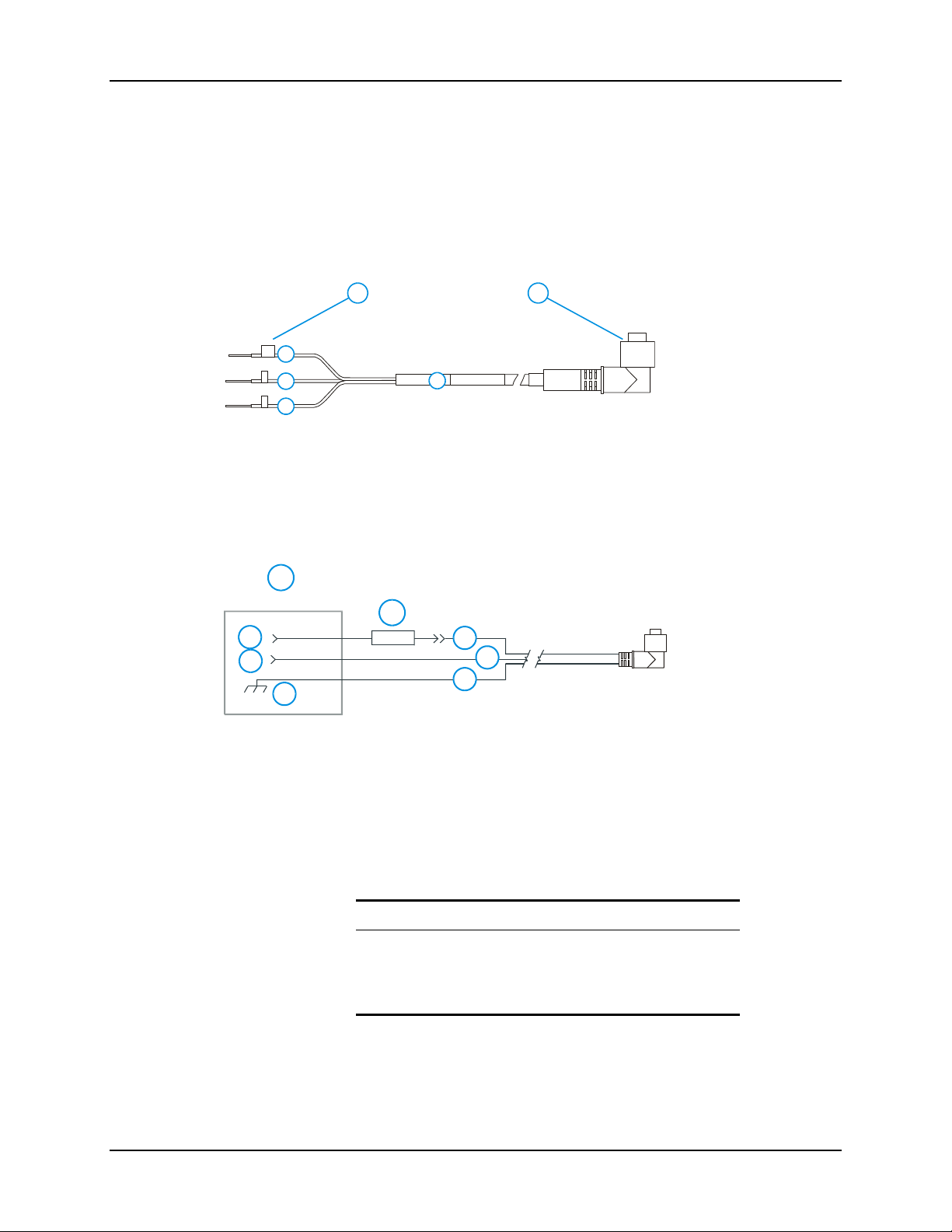
52 Vehicle 12-80VDC Direct Connection
Vehicle 12-80VDC Direct Connection
Note: Instructions for using this configuration are contained in “VX5 User’s Guide” section
titled “Installation”.
1. To Vehicle Battery
1 2
2. To Vehicle
Mounted Device
or UPS Battery
Pack
GND
3
+
4
-
5
6
3. Green (GND)
4. Red / White (DC+)
5. Red / Black (DC-)
6. 12 – 80 VDC
Figure 3-2 Direct Vehicle Power Connection Cable (12 Ft.)
1. Vehicle Electrical
System
1
2
3
4
5
6
7
8
2. 5 Amp Slow
Blow Fuse
3. DC +
4. DC -
5. Vehicle Chassis
6. Red / White
7. Red /Black
8. Green
Figure 3-3 Connecting the Power Cable to the Vehicle
Note: Correct electrical polarity is required for safe and proper installation. Connecting the
cable to the VX5 with the polarity reversed will cause the VX5’s fuse to be blown. See the
following table for wire color-coding specifics.
Wiring color codes for LXE supplied DC input power cabling:
Vehicle Supply Wire Color
+12 - 80VDC (DC +) Red with White Stripe
Return (DC -) Red with Black Stripe
Vehicle Chassis (GND) Green
Figure 3-4 Vehicle Connection Wiring Color Codes
VX5 Reference Guide E-EQ-VX5RG-A
Page 63
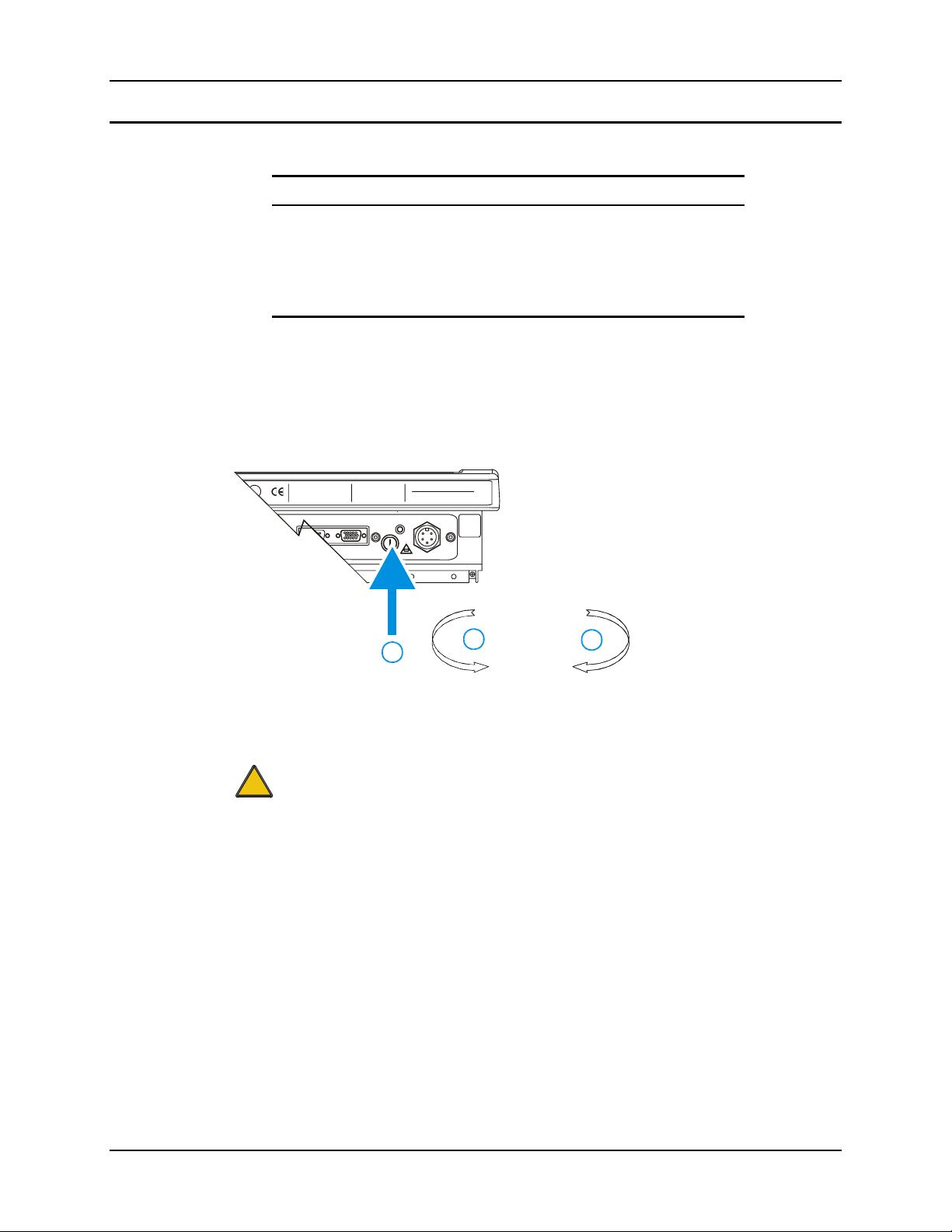
Fuse 53
VX5 Input Power Specifications
Feature Specification
DC Input Voltage 12 - 80 VDC
Input Current 3.5 Amps
Input Fuse 5A Time Delay
Input Power Switch SPST 6 Amp 125VDC
Fuse
The VX5 uses a 100V, 10A time delay (slow blow), high current interrupting rating fuse that is
externally accessible and user replaceable. Should it need replacement, replace with same size,
rating and type of fuse – Littlefuse 0234010 or Optifuse MSC-10A (5x20mm).
U
US
C
L
®
PRODUCT OF U.S.A. U.S. PATENT 5862393
Caution:
!
THIS DEVICE COMPLIES WITH PART 15 OF THE FCC RU LES.
OPERATION IS SUBJECT TO THE FOLLOWING TWO
CONDITIONS: (1) THIS DEVICE MAY NOT CAUSE HA RMFUL
INTERFERENCE, AND (2) THIS DEVICE MUST ACCEPT ANY
INTERFERENCE RECEIVED, INCLUDING INTERFERENCE
THAT MAY CAUSE UNDESIRED OPERATION.
This Class A digital apparatus complies with
Canadian ICE-003.
Cet appareil num de la Classe A est
confirme l
ETHERNET /
USB
érique
orme NMB-003 du Canadaà n
AUDIO
CAUTION: For continues protection against risk of fire,
replace only with same type and rating of fuse.
ATTENTION: Pour ne pas compromette la preotection
contre les risques d'incendie, remplacer par un fusible
de m mes types de m mes caract ristques nominales.êêé
INPUT:
12-80VDC
6A 72W
T10A, 125V
1. Fuse
2. Twist in this direction
to remove
3. Twist in this direction
to insert
2
3
1
Figure 3-5 Fuse Replacement
Fuse has voltage on it even when power is off. Always disconnect input power
before changing fuse.
E-EQ-VX5RG-A VX5 Reference Guide
Page 64

54 Fuse
VX5 Reference Guide E-EQ-VX5RG-A
Page 65
Introduction
BIOS Setup
Chapter 4 System Configuration
Like any personal computer, there are many aspects to the setup and configuration of the VX5.
Much of the setup and configuration of the VX5 is dependent upon the optional features (both
hardware and software) installed on the computer. Since the VX5 uses the Microsoft Windows
Plug and Play operating system, much of the hardware setup is automatic. The examples found in
this chapter are to be used as samples only; the configuration of your specific computer may vary.
The following sections provide a general reference for the configuration of the VX5 and its
optional features.
Please refer to commercially available Microsoft Windows user guides or to
Windows on-line Help application for more information on Windows’ options for
system configuration.
LXE installs Microsoft Windows on the VX5 before shipping. The default BIOS parameters are
configured at that time. In most cases, it is unnecessary to modify the BIOS parameters.
Generally, it is only necessary to enter the BIOS setup to change the boot order of the drives.
Note: Some BIOS parameters described in this section may not be available on all VX5’s.
Caution:
!
Note: Make sure there is an uninterrupted power supply connected to the VX5 before accessing
Be very careful when using this utility to modify BIOS Setup parameters. The VX5
may generate unexpected results when incorrect or conflicting parameter values
are entered. Selecting incorrect or invalid options may require the VX5 to be
returned to LXE for repairs.
The parameters should only be modified by Information Services personnel or the
system administrator.
BIOS Setup.
E-EQ-VX5RG-A VX5 Reference Guide
Page 66

56 BIOS Setup
Windows Management Instrumentation
VX5 BIOS includes support for Windows Management Instrumentation (WMI). The information
displayed by selecting Programs|Accessories|System Tools|System Information from the
Windows Start Menu identifies the System Manufacturer as “LXE Inc.” and the System Model as
“VX5”.
Windows Management Instrumentation (WMI) is a component of the Microsoft Windows
operating system and is the Microsoft implementation of Web-Based Enterprise Management
(WBEM). WBEM is an industry initiative to develop a standard technology for accessing
management information in an enterprise environment. WMI uses the Common Information
Model (CIM) industry standard to represent systems, applications, networks, devices, and other
managed components. You can use WMI to automate administrative tasks in an enterprise
environment.
Windows Management Instrumentation (WMI) is a component of the Microsoft Windows
operating system that provides management information and control in an enterprise environment.
By using industry standards, managers can use WMI to query and set information on desktop
systems, applications, networks, and other enterprise components. Developers can use WMI to
create event monitoring applications that alert users when important incidents occur.
In order to get specific system attributes to return valid data is very simple. The values are pulled
from the SMBIOS data structure. The following attributes are populated with LXE specific
information:
Within the Win32_ComputerSystemProduct class
Caption = "Computer System Product"
Description = "Computer System Product"
IdentifyingNumber = this field is populated by the Kontron Serial number, if
available. If not available, this field contains a ‘serial number not available
message’.
Name = "VX5" [This is equivalent to the Model Number]
Vendor = LXE Inc [This is equivalent to the Make Number]
Within the Win32_SystemEnclosure
ChassisTypes = 8 (Note that some applications may display “portable”, which is
equivalent to the value 8)
Manufacturer = LXE Inc
VX5 Reference Guide E-EQ-VX5RG-A
Page 67

BIOS Setup 57
Accessing the BIOS Setup
When you turn the VX5 on, the unit starts to boot. Watch the bootup sequence and when the
following is displayed:
Press F2 to Enter Setup
Press the [F2] key.
Note: The “Press F2 to Enter Setup” message may be disabled in the BIOS. The F2 key still
has the same function when the display of the message is disabled.
BIOS Setup has six menus: Main, Advanced, Security, Power, Boot and Exit.
Using the Keypad
The set of keypad commands used to select menu items and parameters, as well as modify
parameter values is as follows:
Action Keypress
Exit a menu Esc
Activate Help Screen F1
Modify parameter value Space key or alpha-numeric key
Move to next parameter Enter or Arrow Key
Move from menu to menu Arrow key
Note: Refer to Appendix A “Key Maps” for other key press sequences.
E-EQ-VX5RG-A VX5 Reference Guide
Page 68
58 BIOS Setup
BIOS Setup Default Values by Option
Menu Option Menu / Section Default Value
Boot Boot Device Priority Removable Devices (i.e. USB floppy
drive), Hard Drive, CD-ROM drive,
Network boot (i.e. PXE) in this order
Onboard LAN RPL ROM Boot Disabled
Power Savings Power Disabled 5
Power Supply Power ATX
Rpt Delay Advanced / Keyboard 1/2 sec 5
Rpt Rate Advanced / Keyboard 30 /sec 5
Dark Boot Boot Disabled (displays diagnostic screen
during boot)
Summary Boot Disabled
Settings are saved temporarily as each parameter activity screen is closed. Changes are saved to
CMOS RAM when Exit With Save is selected and the BIOS setup program closes.
Changed parameter values take effect when the VX5 reboots upon exiting BIOS Setup. If the
VX5 does not automatically reboot upon exit, please reboot the VX5.
5
Refer to commercially available Windows guides or Windows help files as these items may be
configured via Microsoft Windows Control Panel.
VX5 Reference Guide E-EQ-VX5RG-A
Page 69

BIOS Setup 59
Main Menu Options
To edit parameters, use the up and down arrow key to move from parameter to parameter.
Use the space key or an alpha-numeric key to modify a parameter value.
Press F1 to activate the help screen. Then use the panning function to move around the help
screen. Press ESC to close the help screen.
Use the left and right arrow keys to move from menu to menu.
Press the ESC key or key sequence to go directly to the Exit Menu.
When changes have been made, press an arrow key to go to another parameter or menu or press
ESC to go to the Exit Menu.
Menu Option Default Value
System Time
System Date
Legacy Diskette (A: and B:) Disabled
Primary Master Auto
Primary Slave Auto
6
Secondary Master Auto
Secondary Slave Auto
Memory Shadow ---
Memory Cache ---
System Memory 640KB
Extended Memory 252928KB
6
Settings are saved temporarily as each parameter activity screen is closed. Changes are saved to
CMOS RAM when “Save and Exit” is selected and the BIOS Setup program closes.
Changed and saved parameter values take effect after the VX5 is rebooted.
Legacy Diskette (A and B)
This option is used to indicate if a floppy disk drive is attached to the VX5. The VX5 does not
have a provision for a standard floppy drive; however, a USB floppy may be attached to the USB
interface cable.
Values:
Disabled No floppy drive present.
360KB 5¼” The option chosen will depend
1.2MB 5¼” on the drive attached. Most
720KB 3½” common are 1.44MB 3½” drives.
1.44/125MB 3½”
2.88MB 3½”
Default: Disabled
6
The secondary drive is either an ATA Compact Flash or ATA PCMCIA card. Please refer to
“ATA Secondary Drive” later in this chapter for more information.
E-EQ-VX5RG-A VX5 Reference Guide
Page 70

60 BIOS Setup
Primary and Secondary Master and Slave Drives
Use this option to indicate the type of disk drive installed in the VX5.
Values:
Auto Auto-detects the hard drive installed, if any.
User User enters parameters of the installed hard
1-39 Select hard drive from pre-determined types.
CD-ROM A CD-ROM is installed here.
ATAPI Removable A removable disk drive is installed.
Default: Auto
Note: The secondary drive is the enabled ATA slot on the side of the VX5. This drive may be
either a PCMCIA or Compact Flash (via PCMCIA adapter) ATA drive. Please see
“ATA Secondary Drive” later in this chapter for more details.
drive.
VX5 Reference Guide E-EQ-VX5RG-A
Page 71

BIOS Setup 61
Advanced Menu Options
The Advanced Menu contains several sections – Advanced Chipset Control, PCI Configuration,
Keyboard Features, and I/O Device Configuration.
To edit parameters, use the up and down arrow key to move from parameter to parameter.
Use the space key or an alpha-numeric key to modify a parameter value.
Press F1 to activate the help screen then use the arrow keys to scroll through the help screen.
Press ESC to close the help screen.
Use the left and right arrow keys to move from menu to menu.
Press the ESC key or key sequence to go directly to the Exit Menu.
Menu Option Default Value
Advanced Chipset Control ---
PNP OS Installed No
Reset Configuration Data No
Secured Setup Configuration Yes
PCI Configuration ---
PS/2 Mouse Auto Detect
Keyboard Features ---
I/O Device Configuration ---
Hardware Monitor ---
Large Disk Access Mode DOS
Settings are saved temporarily as each parameter activity screen is closed. Changes are saved to
CMOS RAM when “Save and Exit” is selected and the BIOS Setup program closes.
Changed and saved parameter values take effect after the VX5 is rebooted.
Advanced Chipset Control
Parameters in this menu have been selected for best performance from your VX5. Changes are
not recommended.
PCI Configuration
Parameters in this menu have been selected for best performance from your VX5. Changes are
not recommended.
E-EQ-VX5RG-A VX5 Reference Guide
Page 72

62 BIOS Setup
Keyboard Features
NumLock
Keyclick
Note: Some VX5 keyboards do not have a NumLock indicator or key. For these keyboards,
NumLock may be toggled using the <2
Use this option to set NumLock at boot time. When NumLock is On, the keypad is locked in
numeric mode. When NumLock is Off the numeric keys are inoperable.
Whether NumLock at Boot is Off or On, no LED is illuminated on the VX5.
Values: Auto, On, Off
Default: Auto
Enables the click on a keypress.
Values: Enabled, Disabled
Default: Disabled
nd
> <SHIFT> <F10> keypress sequence.
VX5 Reference Guide E-EQ-VX5RG-A
Page 73

BIOS Setup 63
I/O Device Configuration
Serial Port (A and B)
These parameters determine if the integrated serial port is active.
Values:
Disabled Port is not active.
Enabled User must define port by specifying base
I/O address and interrupt.
Auto BIOS or OS configured.
OS Cntrl Controlled by OS
Default: Auto
Note: To switch pin-9 of the port between RI and +5v, it is necessary to change jumpers on the
system board. See “Serial Port Pin 9” later in this chapter.
Onboard LPT
These parameters determine if the integrated parallel port is active.
Values:
Disabled Port is not active.
Enabled User must define port by specifying base
Auto BIOS or OS configured.
OS Cntrl Controlled by OS
Default: Disabled
Note: There is no parallel port (LPT1) on a VX5. Disabling the LPT1 port allows IRQ7 to be
used by other devices.
USB Port / USB Host Controller
These parameters determine if the USB port is active.
Values: Enabled, Disabled
Default: Enabled
Note: The USB adapter cable must be attached to the VX5 to use the USB port.
USB BIOS Legacy Support
Enables support for USB keyboard and mice.
Values: Enabled, Disabled
Default: Enabled
I/O address and interrupt.
Note: To boot from a USB floppy, USB BIOS Legacy Support must be enabled.
E-EQ-VX5RG-A VX5 Reference Guide
Page 74

64 BIOS Setup
Security
This menu can be used to set security features as desired.
Power
BIOS power management is disabled in the VX5. Microsoft Windows handles all power
management.
Boot
Floppy Check
This parameter determines if the floppy drive is verified on boot. Disabling provides a faster
boot.
Values: Enabled, Disabled
Default: Disabled
Summary Screen
This parameter determines if the summary screen should be displayed on bootup. Disabling
provides a faster boot.
Quickboot Mode
This parameter determines if certain tests should be skipped during boot. Enabling provides a
faster boot.
Dark Boot
This parameter prevents diagnostic output to the screen during boot.
Values: Enabled, Disabled
Default: Disabled
Values: Enabled, Disabled
Default: Enabled
Values: Enabled, Disabled
Default: Enabled
VX5 Reference Guide E-EQ-VX5RG-A
Page 75

BIOS Setup 65
Boot Device Priority
The bootable devices are listed in the order they are searched.
Removable Devices
+ Hard Drive
ATAPI CD-ROM Drive
Network Boot
Any item listed with a “+” contains an expandable list of devices. Highlight the item and press
the <Enter> key to expand the list.
Removable Devices
- Hard Drive
Secondary Master
Bootable Add-In Cards
Primary Master
ATAPI CD-ROM Drive
Network Boot
7
7
This is the default boot order delivered with your VX5. Valid functions are:
• Highlight a device and press <+> to move it up the list of devices.
• Highlight a device and press <-> to move it down the list of devices.
• <Enter> expands an item with a “+” and contracts an item with a “-”.
• <2nd>+<Shift>+<1> disables or enables a device. Any disabled device is displayed
Onboard LAN RPL ROM
Enables remote boot BIOS extensions for the onboard LAN controller (Ethernet port). RPL
stands for Remote Program Load.
Values: Enabled, Disabled
Default: Disable
with an “!”.
7
Hard drives may be identified by the manufacturer name. In those cases, the (PM) or (SM)
listed after the drive name identifies the drive as Primary Master or Secondary Master.
E-EQ-VX5RG-A VX5 Reference Guide
Page 76

66 BIOS Setup
Exit Menu Options
To edit parameters, use the up and down arrow key to move from parameter to parameter.
Press F1 to activate the help screen then use the panning function to move around the help screen.
Press ESC to close the help screen.
Use the left and right arrow keys to move from menu to menu.
Press the ESC key or key sequence to go directly to the Exit Menu.
As changes are made to Setup values, the values can be saved or discarded. The next time the
VX5 is turned on or rebooted, the saved values take effect.
Exit Saving Changes
Use this option to immediately save current Setup settings to CMOS RAM and into the Flash Boot
Device (FBD).
When “Save and Exit” is highlighted, press <Enter> to save. When the saving process is
complete, the VX5 reboots with the current values.
Exit Discarding Changes
Use this option when any current changes made to Setup parameters are to be ignored. The
parameters revert to their state when Setup was entered.
When this option is highlighted, press <Enter> and the boot process continues. The system
reboots with unchanged values.
Load Setup Defaults
This option is used to reset the Setup values to the original, default values that were set at the
factory, before suppliers or end users made changes.
The next time the VX5 is turned on or rebooted, those saved values are in effect. Save this
change by selecting “Save and Exit.”
Discard Changes
Use this option to immediately restore CMOS RAM and update the current Setup settings from
the Flash Boot Device.
Save this change by selecting “Save and Exit.”
Save Changes
Used to save BIOS Setup changes without rebooting. The changed parameters are in effect the
next time the VX5 is powered on or rebooted.
Reboot by selecting either “Exit w/o Save” or “Save and Exit.”
VX5 Reference Guide E-EQ-VX5RG-A
Page 77
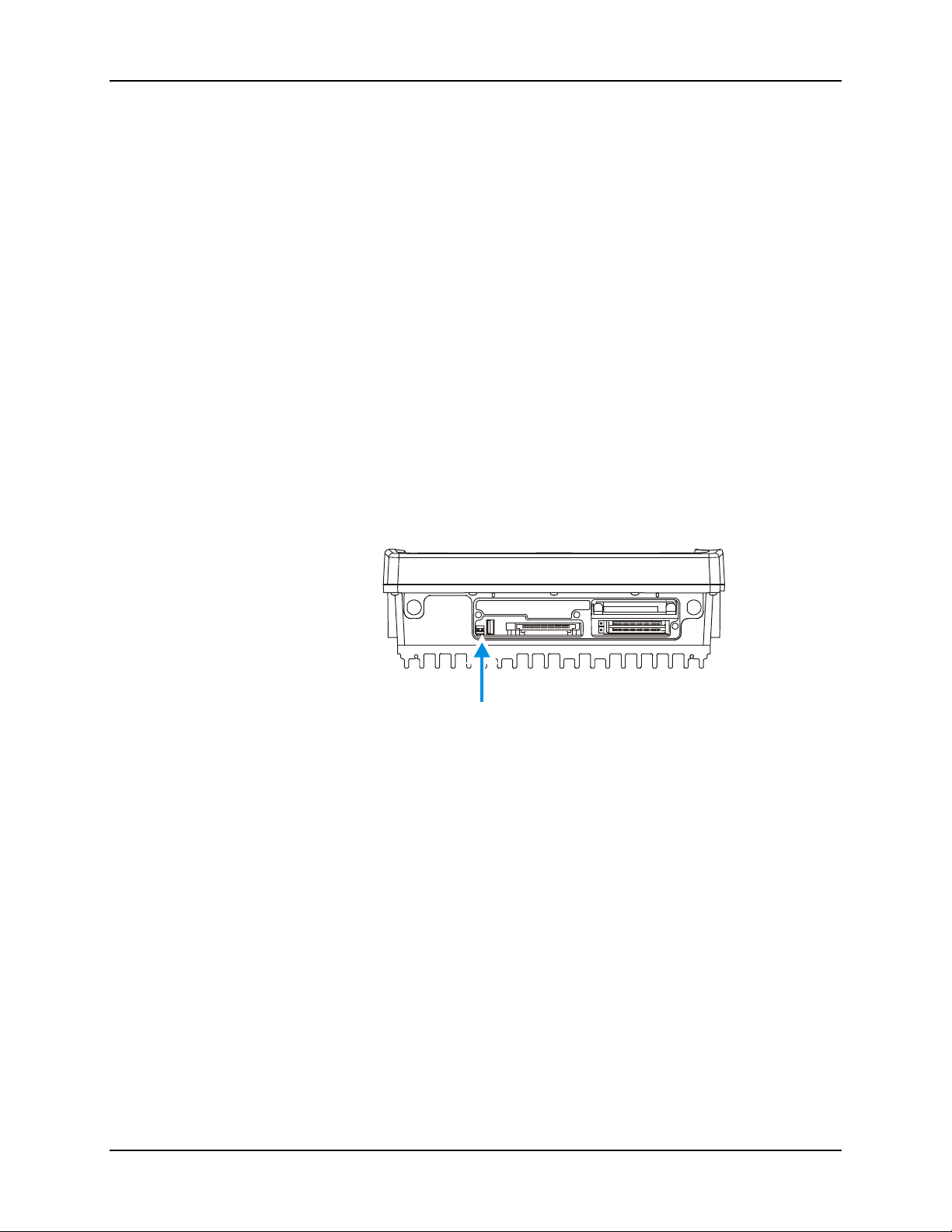
Serial Port Pin 9 67
Serial Port Pin 9
Pin 9 of the serial ports may be configured to provide RI or +5V using DISP switches accessible
by removing the access cover:
• Pin 9 must be set to +5V if an external serial scanner is to be attached. This is the
default setting for COM1 and provides 400mA maximum.
• Pin 9 must be set to RI if a serial printer or PC cable is to be used with the port. This
is the default setting for COM2.
Equipment Needed: Phillips No. 1 screwdriver, a Torque wrench capable of measuring to 9±1
inch pounds (1.016 ±.11 N/m).
Note: Torquing tool is not supplied by LXE.
1. Turn the VX5 off and remove the power supply before opening the access cover located
on the top of the VX5.
2. Loosen the three (3) Phillips screws securing the access cover so the cover can be
removed. The screws are a captive part of the cover and cannot be removed.
3. Remove the access cover. The cover is tethered to the VX5 to prevent loss.
Figure 4-1 DIP Switch Location
Note: The tethered access panel cover is not shown in the illustration above.
4. Refer to the legend above the DIP switches. There are two DIP switches, one for
COM1 and one for COM2. When a DIP switch is in the Up position, the COM port pin
9 is configured for a scanner (+5V). When a DIP switch is in the Down position, the
COM port pin 9 is configured for RI.
5. After setting the dip switches to the desired position, reattach the access cover screws
using a torque wrench capable of measuring 9±1 inch pounds (1.016±.11 N/m). The
three screws must be fastened to 9 inch pounds each. The screws require a Phillips size
1 driver head.
E-EQ-VX5RG-A VX5 Reference Guide
Page 78

68 VMT Keyboard Backlighting
VMT Keyboard Backlighting
95-key Keyboard
This LXE keyboard has keys that are backlit with LEDs. The backlight is manually controlled
using the “backlight” key in the upper right hand corner of the keyboard. Pressing the backlight
key cycles the backlight through the levels of backlight intensity:
• Off
• Maximum intensity
• Medium intensity
• Low intensity.
60-key Keyboard
This LXE keyboard has LEDs that illuminate the individual keys. The keyboard backlight may be
toggled manually by pressing <2
changes the state of the keyboard backlight as follows:
• Turns the backlight Off if it is currently On.
• Turns the backlight On if it is currently Off.
nd
> + <CTRL> + <F10>. This key sequence immediately
Microsoft Windows Setup and Configuration
Options for the VX5 include Windows 2000 Professional and Windows XP Professional
preinstalled. If your VX5 was ordered with no Operating System, please see “VX5 Delivered
with No OS” later in this chapter.
Note: The VX5 System Tools CD-ROM (LXE Part No. VX5A477DRIVERS) contains files that
may be used during Microsoft Windows setup and Configuration. Please refer to the
section detailing the contents of this CD later in this chapter.
VX5 Reference Guide E-EQ-VX5RG-A
Page 79

Microsoft Windows Setup and Configuration 69
Microsoft Windows License Agreement (First Boot)
If your VX5 is shipped with a Microsoft Windows operating system pre-installed, it is
necessary to complete the Windows licensing/registration screens when starting the
VX5 for the first time. To complete this information, you need the Microsoft
Windows software/product key that was included with the VX5.
Note: If you are installing a Microsoft Windows operating system on a VX5 delivered with no
OS, you may be prompted for the Windows software or product key and registration
information either during installation or upon first boot.
Microsoft Windows 2000
The Microsoft Windows software key is a 25 digit key included with the VX5.
The first screen prompts for the name (individual or corporation) to which Microsoft Windows is
registered. After the information is entered, press or click on the “Next” button.
The second screen displays Microsoft’s licensing agreement. Review the agreement and indicate
if you wish to accept the agreement.
Note: If you do not accept the agreement, Microsoft Windows does not continue to load.
The next screen asks for the software key. Enter the key exactly as it is displayed on the decal.
Note: If you ordered multiple VX5’s, a separate key code decal is included for each VX5. Each
key code is to be used on only one VX5. Be sure to store the key codes in a safe place.
Pressing “Next” finishes the licensing/registration process.
As Microsoft Windows starts for the first time, you are asked to verify the time and time zone.
Make any necessary changes and Windows finishes its setup and starts for the first time.
Microsoft Windows XP
When Microsoft Windows XP is started by the user for the first time (known as the “out of the
box experience”), a series of questions is presented. The product key (printed on a decal attached
to the VX5) must be entered. The series of prompts and responses allow the user to configure
Microsoft Windows XP on the VX5 according to the user’s needs.
During this process it is normal for the “New Hardware Wizard” window to appear. When the
wizard appears and asks for the Ethernet device driver, select “OEMxxx.INF” (where xxx is a
series of numbers, such as OEM123.INF) from the list of available drivers and click Next. When
prompted, click Finish to complete the installation of the Ethernet device.
If you are installing a Symbol radio, the wizard window may appear for the radio driver. Click
Next and then Finish when prompted.
Proceed with the remainder of the boot process.
E-EQ-VX5RG-A VX5 Reference Guide
Page 80

70 Microsoft Windows Setup and Configuration
Drive C Directory Structure
The drive C: directory structure is the same for all media types. Microsoft Windows is installed
in the \Windows or \WINNT directory. The default directory depends on the version installed. In
addition, Microsoft Windows creates other directories and several subdirectories. For more
information on the directories Microsoft Windows uses, please refer to commercially available
Windows reference guides.
Depending on the option ordered, drive C: may be:
• a 40GB rotating drive
• a 2GB flash drive
• a 2GB PCMCIA card
• a user installed drive (a VX5 with the “no hard drive” option)
Please refer to the invoice or packing list if there are any questions about the configuration of your
VX5.
ATTENTION: On a VX5 with a flash drive, powering off the VX5 before a write (to disk)
function has completed, may result in the corruption of the flash drive.
Software Loaded on Drive C
The software loaded on the VX5 computer consists of:
• BIOS
• Microsoft Windows 2000 Professional or Windows XP Professional
• device drivers
• radio software
• touchscreen software
• RFTerm
Note: If your VX5 was ordered with the no OS option, please refer to “VX5 with No OS”, later
in this chapter.
The software installed on the VX5 is summarized below.
Note: Due to the complex directory structure and System Registry under Microsoft Windows,
software should not be removed manually. Instead use the Add/Remove Programs icon
in the Windows Control Panel.
Microsoft Windows
Microsoft Windows is installed in the \Windows (or \WINNT) subdirectory, which is the
Windows default. In addition, Windows places files in other directories and subdirectories during
installation. For more information, please refer to commercially available Windows user guides.
TM
software.
VX5 Reference Guide E-EQ-VX5RG-A
Page 81

Microsoft Windows Setup and Configuration 71
Device Drivers
Device drivers are included for all installed hardware options, such as the display, touchscreen,
radios, Ethernet port, etc. For more information on Microsoft Windows device drivers, please
refer to commercially available Windows guides.
Radio Software
If a radio is ordered with a VX5, the VX5 is delivered with the radio software installed. Because
the VX5 is uses a Microsoft Windows operating system, the radio installation includes Windows
device drivers.
Touchscreen Software
Fujitsu Touch Panel software is installed for calibrating the VX5’s touchscreen. Please see
“Touch Screen Calibration” later in this chapter for more information.
TM
RFTerm
RFTerm allows users to connect to applications running on IBM 3270, AS/400 and VT hosts from
an LXE Microsoft Windows based mobile computer over a wireless TCP/IP data network.
Software
E-EQ-VX5RG-A VX5 Reference Guide
Page 82

72 Microsoft Windows Setup and Configuration
Microsoft Windows Configuration
After the system files are processed, Microsoft Windows begins to load. Windows maintains a
System Registry and INI files. Standard Windows configuration options apply to the VX5.
Configuration options are located in either the System Tray or the Control Panel:
• The System Tray contains icons for adjusting the time, date or volume level.
• The Control Panel contains icons for many other configuration options, such as
Power Management, PC Cards, etc.
• The Control Panel icons are also used to add, delete or modify hardware installed on
the VX5.
Please refer to Microsoft Windows help screens or commercially available
Windows guides for more information on configuration options in Windows.
VX5 Reference Guide E-EQ-VX5RG-A
Page 83
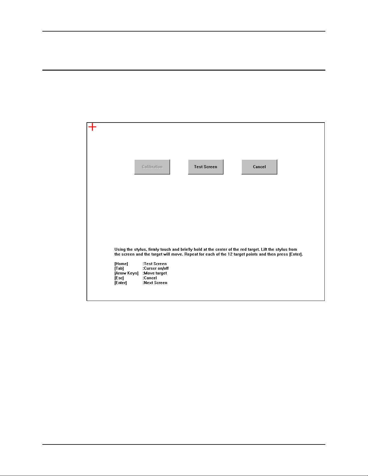
Touchscreen 73
Touchscreen
Calibrating the Touchscreen
Although the touch screen is installed and calibrated at the factory, users may make adjustments to
it by using the Fujitsu Touch Panel on the Microsoft Windows Programs menu. To calibrate the
touchscreen, select Start|Programs|Fujitsu Touch Panel (USB)|Touch Screen Calibration
Utility.
Figure 4-2 Touchscreen Calibration
The calibration utility displays a red cross on the screen. Touch the center of the cross with the
stylus and hold for a few seconds. Release and repeat with the next cross. After all twelve
locations have been touched, either press <Enter> or click the Calibration button.
E-EQ-VX5RG-A VX5 Reference Guide
Page 84
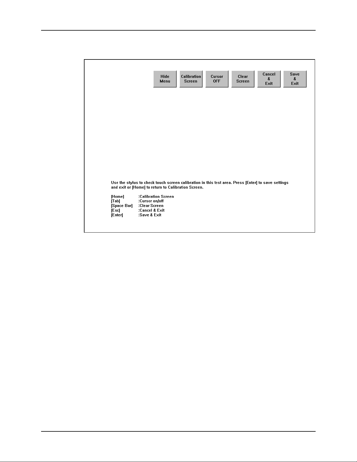
74 Touchscreen
Figure 4-3 Touchscreen Calibration
To save the new calibration settings, click on the Save & Exit button or press <Enter>.
To discard the new calibration settings, click Cancel & Exit or press <Esc>.
VX5 Reference Guide E-EQ-VX5RG-A
Page 85
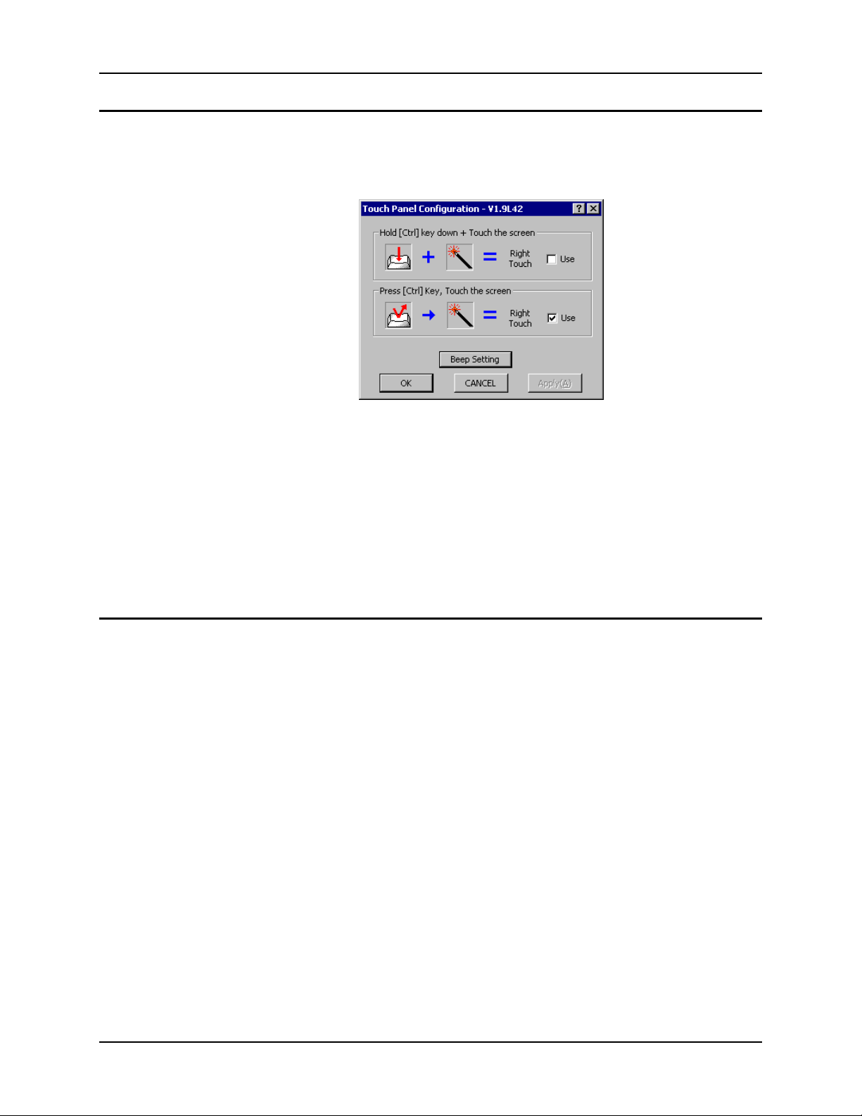
Touchscreen 75
Configuring Right Click on the Touchscreen
The Fujitsu Touch Panel configuration is accessed from the Programs section of the Microsoft
Windows Start menu. Use this utility to configure the “right click” behavior of the touch screen.
Figure 4-4 Touch Panel Configuration
The touch screen right click behavior can be configured as followed:
• Holding the <Ctrl> key and then touching the screen if the first option is selected
• A screen touch after the <Ctrl> key is pressed if the second option is selected.
Note: Because the <Ctrl> key is a “sticky key” on the 60-key keyboard, the first option must be
used with this keyboard. Once the <Ctrl> key is pressed on the 60-key keyboard, the
<Ctrl> key stays active (and every screen touch is treated as a right click) until another
key is pressed on the keyboard.
Disabling the Touch Screen
If desired, the touchscreen can be disabled in the Windows control panel. Once disabled, the
touchscreen remains disabled until it is enabled again.
To disable the touchscreen, access the Windows control panel and click on
System|Hardware|Device Manager|Human Interface Devices. Under the Human Interface
Devices there is a listing for Fujitsu Touch Panel (USB). Right click on this listing and select
Disable from the menu.
To enable the touchscreen, follow the same process, selecting Enable from the right click menu.
E-EQ-VX5RG-A VX5 Reference Guide
Page 86

76 Network Configuration
Network Configuration
There are two networking options available for the VX5:
• 2.4GHz wireless radios
• Ethernet (RJ-45) connector.
2.4 GHz Wireless Radios
Please refer to Chapter 5, “RF Network Configuration” for details on configuring the 2.4 GHz
wireless radio cards.
Ethernet Connector
When the VX5 is networked using the Ethernet connector, the VX5’s networking options are set
via the Microsoft Windows Control Panel. The same networking configuration options are
available as in a standard PC.
For more information on configuring the Microsoft Windows network settings,
please refer to the Windows Help feature or commercially available Windows
networking literature.
VX5 Reference Guide E-EQ-VX5RG-A
Page 87
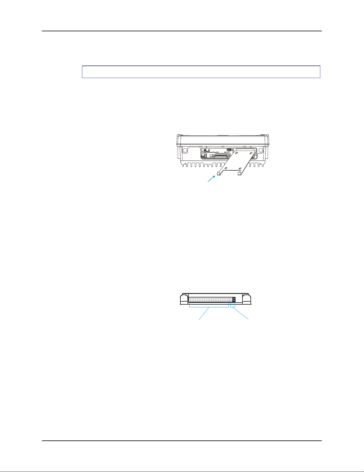
VX5 Delivered with No Hard Drive 77
s
VX5 Delivered with No Hard Drive
How To Install 2.5” IDE Hard Drive
1. Turn the VX5 off and remove the power supply before opening the access cover
located on the top of the VX5.
2. Loosen the three (3) Phillips head screws securing the access cover so the cover can
be removed. The screws are a captive part of the cover and cannot be removed.
3. Slide the Hard Drive Sled (or bracket) out of the VX5.
COM1COM2
Hard Drive Sled
IDE DRIVE
SCANNER
CARD BUS A
SERIAL
CARD BUS B
USB
PCMCIA/CF ATA
Figure 4-5 Hard Drive Sled
Note: The tethered access panel cover is not shown in the illustration above.
4. Attach the hard drive to the hard drive sled, using 4 M3x4 flat head screws inserted
through the holes in the bottom of the hard drive sled. Torque to 8.0±1 in/lb
(0.9±.11 N/m). The VX5 accepts 2.5” IDE flash or rotating hard drives.
5. Insert the hard drive into the VX5. Slide the assembly into the opening from which
the empty bracket was removed. Do not slide it all the way in.
6. Connect the hard drive cable to the connector pins on the back of the hard drive.
Make sure the cable is centered correctly on the connector pins. Do not attempt to
place the hard drive cable over the jumper pins.
Hard Drive Cable
Connector Pins
Hard Drive
Jumper Pin
Figure 4-6 Hard Drive Connector Pins
7. Insert the hard drive assembly the rest of the way into the VX5.
8. Reinstall the access panel cover, torquing the screws to 9±1 inch pounds (1.016±.11
N/m). The screws require a Phillips size 1 driver head.
9. If the VX5 displays a message such as “operating system not found” during the first
boot with the new hard drive, it may be necessary to reboot. The error may be
eliminated with a reboot. If the error persists, please review the BIOS settings for
the primary hard drive. Also check the hard drive documentation for the proper
jumper settings.
E-EQ-VX5RG-A VX5 Reference Guide
Page 88

78 VX5 Delivered with No OS
VX5 Delivered with No OS
Note: This section applies only to a VX5 ordered with no OS installed.
If the ‘no Operating System (OS)’ option was chosen when ordering the VX5, two possible
options for installing the OS are detailed in this section:
TM
• Install the OS using Norton Ghost
• Install the OS over the network.
Additionally, a Microsoft Windows image can be created on a hard drive before it is installed in
the VX5. See “VX5 Delivered with No Hard Drive” earlier in this chapter for information on
installing a hard drive in the VX5.
Note: It is assumed that the OS to be installed is Microsoft Windows.
It is necessary to make changes to the BIOS when using either of these options to install an OS.
Please refer to “BIOS Setup” earlier in this chapter for more details.
The VX5 System Tools CD (LXE Part No. VX5A477DRIVERS) contains device drivers that are
necessary when installing Microsoft Windows on a VX5 delivered with no OS. The device
drivers contained on this CD need to be available during the Windows installation/configuration.
For example, the drivers can be copied to a location where they can be accessed via network or
USB floppy. Please see the section detailing the contents of this CD-ROM later in this chapter.
.
After installing Microsoft Windows, please refer to “Microsoft Windows Setup and
Configuration” earlier in this chapter.
Installing Microsoft Windows with Norton Ghost
The requirements and process for using Norton Ghost depend on the version of
Microsoft Windows to be installed on the VX5.
Microsoft Windows 2000
To use the Norton Ghost utility to install an OS, there must be a blank drive connected to the
Primary IDE and a Compact Flash or ATA drive with a ghost image connected to the Secondary
IDE.
Note: This procedure can also be used with Microsoft Windows NT. For NT versions of
Windows, the image must be created on the same type of computer as the destination
computer where the OS is to be used. Differences in hardware may keep NT from
booting after it is loaded on the destination computer.
Hardware Required
• A PC where the original image will be produced.
• A Micro drive, PCMCIA ATA flash drive or Compact Flash drive that is at least
10MB larger than the ghost image.
Software Required
• Norton Ghost 2002 or newer
• Microsoft Windows image
VX5 Reference Guide E-EQ-VX5RG-A
Page 89

VX5 Delivered with No OS 79
How To Install Microsoft Windows 2000
1. With the primary hard drive installed in the VX5, insert a bootable Compact Flash or
PCMCIA ATA drive into the secondary IDE slot. This drive should contain the ghost image
and the Norton Ghost utility 2002 or newer.
2. Boot the VX5 and enter the BIOS by pressing F2.
Note: Refer to “BIOS Setup” earlier in this chapter for more information on the BIOS
changes made during this process.
3. Select Advanced|I/O Device Configuration and ensure that the Local Bus Adapter is set to
“Both”.
4. Press <Esc> to return to the main menu.
5. Select Boot|Boot Device Priority and make sure the Secondary IDE device is first in the boot
order.
• Press <Enter> while “Hard Drive” is highlighted to expand the listing
• Highlight the Secondary IDE device in the listing and press <2nd> <+> until it is
listed before the Primary hard drive.
6. Save any changes made and allow the VX5 to boot.
7. Follow the instructions for the version of Ghost you are using to copy the ghost image from
the Secondary IDE to the Primary IDE drive.
8. Once the image has been copied, power the VX5 down and remove the secondary drive.
9. Restart the VX5 and edit the BIOS to return the Primary IDE to the top of the boot order.
10. Save the change and reboot the VX5.
11. After the VX5 boots, verify that the image has been transferred and the unit is operating
correctly.
Note: You may wish to review the “Microsoft Windows Setup and Configuration” section,
earlier in this chapter, to set up Windows as desired.
E-EQ-VX5RG-A VX5 Reference Guide
Page 90

80 VX5 Delivered with No OS
Microsoft Windows XP
To use the Norton Ghost utility to install an OS, there must be a blank drive connected to the
Primary IDE and a Compact Flash or ATA drive with a ghost image connected to the Secondary
IDE.
Note: This procedure can also be used with Microsoft Windows NT.
Hardware Required
• A PC where the original image will be produced.
• A Micro drive, PCMCIA ATA flash drive or Compact Flash drive that is at least
10MB larger than the ghost image.
• TEAC USB floppy drive or equivalent bootable USB floppy drive.
Note: Not all USB floppy drives are bootable devices.
Software Required
• Norton Ghost 2002 or equivalent
• Microsoft Windows image
VX5 Reference Guide E-EQ-VX5RG-A
Page 91

VX5 Delivered with No OS 81
How To Install Microsoft Windows XP
To install Microsoft Windows XP using Ghost 2002 or newer, a Ghost boot floppy is required.
You will also need the Ghost license number from the Ghost program that made the Windows XP
image. To make the Ghost floppy:
1. From Microsoft Windows, start the Ghost 2002 Boot Wizard.
2. Choose “Boot Disk with CD/R”
3. Connect the USB floppy drive to the VX5.
4. Boot the VX5 and enter the BIOS by pressing F2.
Note: Refer to “BIOS Setup” earlier in this chapter for more information on the BIOS
changes made during this process.
5. Select Advanced|I/O Device Configuration and ensure that the USB Controller and USB
Legacy Support are enabled.
6. Press <Esc> to return to the main menu.
7. Select Boot|Boot Device Priority and make sure that “Removable Devices” is listed first in
the boot order.
8. Save any changes and exit the BIOS setup.
9. Insert the Ghost floppy in USB floppy drive and allow the VX5 to boot from the floppy.
10. Follow the directions to transfer the Microsoft Windows XP image to the VX5 hard drive.
Note: Do not restart the VX5 with Microsoft Windows running until you are ready to
perform the “Out of box experience” process detailed earlier in this chapter. Please
refer to “Microsoft Windows License Agreement” for more details.
11. Restart the VX5 and edit the BIOS to return the Primary IDE to the top of the list (to boot
into Microsoft Windows).
12. Save the change and reboot the VX5.
13. After the VX5 boots, verify that the image has been transferred and the unit is operating
correctly.
Note: You may wish to review the “Microsoft Windows Setup and Configuration” section,
earlier in this chapter, to set up Windows as desired.
E-EQ-VX5RG-A VX5 Reference Guide
Page 92

82 VX5 Delivered with No OS
Installing Microsoft Windows Over a Network
Using a PCMCIA Network Card
This section details installing the operating system over the network. This procedure assumes the
VX5 has a formatted blank hard drive installed as the Primary IDE drive. You will also need
software to enable the PCMCIA slot in which the Ethernet card will reside. For this example, that
software will be Enabler that is delivered with the Socket LP-E Ethernet card.
Hardware Required
• Socket LP-E network card or equivalent.
Note: Bus cards will not fit into the PCMCIA slots.
• TEAC USB floppy drive or equivalent bootable USB floppy drive.
Note Not all USB floppy drives are bootable devices.
• USB adapter cable for VX5.
Software Required
• Bootable Microsoft Windows diskette.
• Software to enable PCMCIA slot.
Note: Enable is included with the Socket LP-E Ethernet card.
• Software needed to connect to your network (ie: ETHDRV.EXE, TCP.EXE,
LSL.COM, odipkt.COM)
How To Install Microsoft Windows 2000 or XP
1. Create a bootable diskette.
2. Copy the utility to enable the PCMCIA slot and any files needed to connect to your network
to the bootable diskette. A sample list of files to be included on the bootable diskette is
included later in this section.
3. Edit all required files to allow the Ethernet card to become active. A list of sample files used
in this process is provided later in this section.
Note: Different cards and different utilities may require different settings.
4. Connect the hardware listed above to the VX5.
5. Boot the VX5 and enter the BIOS by pressing F2.
Note: Refer to “BIOS Setup” earlier in this chapter for more information on the BIOS
changes made during this process.
6. Select Advanced|I/O Device Configuration and ensure that the USB Controller and USB
Legacy Support are enabled.
7. Press <Esc> to return to the main menu.
8. Select Boot|Boot Device Priority and make sure that “Removable Devices” is listed first in
the boot order.
9. Save any changes made and exit the BIOS.
10. Insert the floppy drive and allow the VX5 to boot.
VX5 Reference Guide E-EQ-VX5RG-A
Page 93

VX5 Delivered with No OS 83
11. After connecting to the network, perform all necessary installations.
12. Restart the VX5 and edit the BIOS to return the primary IDE to the top of the boot order.
13. Save the change and reboot the VX5.
14. After the VX5 boots, verify that all software is installed and the unit is operating correctly.
Note: You may wish to review the “Microsoft Windows Setup and Configuration” section,
earlier in this chapter, to set up Windows as desired.
Files on Bootable Diskette
Note: The files included on the boot disk shown below are examples only. The files contained
on your bootable diskette and the directory structure may vary depending on the network
card and software used.
Directory of A:\
COMMAND.COM
NET.CFG
AUTOEXEC.BAT
CONFIG.SYS
HIMEM.SYS
DIR.TXT
EDIT.EXE
ATTRIB.EXE
FDISK.EXE
XCOPY.EXE
FORMAT.COM
QBASIC.EXE
SOCKETLP <DIR>
Directory of A:\SOCKETLP
CIRRFIX.EXE
DRIVER.LST
ENABLELP.EXE
ETHDRV.EXE
FTP.EXE
IPSTAT.EXE
LSL.COM
NE2000.COM
NE2000.INS
NET.CFG
ODIPKT.COM
PCTCP.INI
PING.EXE
SKTID.EXE
TCP.EXE
TFTP.EXE
(See example file below)
(See example file below)
(See example file below)
E-EQ-VX5RG-A VX5 Reference Guide
Page 94

84 VX5 Delivered with No OS
Sample Files for Installation Procedure
Note: The example files shown below are examples only. Your files may differ depending on
the Ethernet card used.
NET.CONFIG
Link Driver NE2000
Port 340
Int 7
; Remove the semi-colon in front of the frame type you will use.
; This frame type must match what the NetWare server is using.
; FRAME Ethernet_802.2
; FRAME Ethernet_802.3
; FRAME Ethernet_SNAP
FRAME Ethernet_II
NetWare DOS Requester
FIRST NETWORK DRIVE = F
; If you know the name of your preferred server, remove the
; semi-colon below and enter the preferred server name after
; the equal sign.
;preferred server =
CONFIG.SYS
DEVICE=HIMEM.SYS /testmem:off
FILES=30
BUFFERS=20
DEVICE=a:\socketlp\enablelp.exe membase=0xE8000 messages=enabled
socket=1
LASTDRIVE=Z
AUTOEXEC.BAT
@echo off
cd\socketlp
LSL
ne2000
odipkt
SET PCTCP=a:\socketlp\pctpc.ini
ethdrv.exe
VX5 Reference Guide E-EQ-VX5RG-A
Page 95

VX5 Delivered with No OS 85
Using the Ethernet Port
This section provides only a general overview of the PXE boot and RIS service.
For complete details, the user should consult Microsoft’s documentation for PXE
and RIS. This information is available on Microsoft’s web site,
www.microsoft.com.
Microsoft Remote Installation Services (RIS) can be used to install a Microsoft Windows
operating system on a VX5 delivered with no OS. RIS uses DHCP based boot technology known
as Preboot eXecution Environment (PXE).
Requirements
• A PC with Microsoft Windows 2000 Server with the following services:
o Remote Installation Services (RIS)
o Domain Name Systems (DNS)
o Dynamic Host Configuration Protocol (DHCP) server
o Active Directory.
• A Microsoft Windows 2000 or XP image to download to VX5 computers.
• A VX5 configured for PXE boot located on the same physical network as the server
PC.
How To Install Microsoft Windows 2000 or XP
1. Connect the VX5 to the network by inserting a network cable in the Ethernet port.
2. Boot the VX5 and enter the BIOS by pressing F2.
Note: Refer to “BIOS Setup” earlier in this chapter for more information on the BIOS
changes made during this process.
3. Select Boot and change “Onboard LAN RPL ROM” to enabled.
4. Press <Esc> to return to the main menu.
5. Select Boot|Boot Device Priority and make sure that “Network boot” is listed first in the
boot order.
6. Save any changes made and exit the BIOS.
7. Allow the VX5 to boot.
8. When the message is displayed, press F12 to connect to the RIS server.
9. When the file transfer is complete, reboot the VX5 and enter the BIOS by pressing F2.
10. Set “Onboard LAN RPL ROM” to disabled. Return primary IDE to the top of the boot order
list.
11. Save any changes made and exit the BIOS.
12. After the VX5 boots, verify that the image has been transferred and the unit is operating
correctly.
E-EQ-VX5RG-A VX5 Reference Guide
Page 96

86 VX5 Delivered with No OS
Installing Microsoft Windows From a CD
This section details installing the Microsoft Windows XP operating system from a CD-ROM.
This procedure assumes the VX5 has a formatted blank hard drive installed as the Primary IDE
drive.
Hardware Required
• VX5 computer with at least 10GB of free space on the hard drive
• Ethernet/USB dongle cable
• External USB CD–ROM drive
Note: The following drives have been tested to work with the VX5:
o IOMEGA CD-RW 52x24x52x USB 2.0 external drive, model number
CDRW55292EXT
o TDK veloCD 5201ue 52x24x48x USB 2.0 external drive, model
number UE-5201B
o HP DVDwriter model number dvd300e
Software Required
• Microsoft Windows XP Professional installation CD
• LXE VX5 Driver CD, part no. VX5A477DRIVERS.
How To Install Microsoft Windows XP
1. Plug the CD drive into the USB connector on the end of the Ethernet/USB dongle cable.
2. Turn the VX5 on and press the F2 key when prompted to enter setup.
Note: Refer to “BIOS Setup” earlier in this chapter for more information on the BIOS
changes made during this process.
3. Select Boot|Boot Device Priority and change the boot sequence to the following order: CD
ROM, Hard Drive, Floppy Drive in that order.
4. Before exiting BIOS, insert the Windows XP Professional CD into the CD drive.
5. Exit and save BIOS changes.
6. During the reboot, watch for the message “Press any key to boot from the CD” and press any
key.
Note: This message appears for a short time only. If no key is pressed before the message
disappears, the VX5 must be rebooted.
7. This starts the Windows XP setup routine. Complete the installation answering the questions
appropriately.
8. Install LXE drivers using the LXE VX5 Drivers CD.
VX5 Reference Guide E-EQ-VX5RG-A
Page 97

The VX5 Drivers CD-ROM 87
The VX5 Drivers CD-ROM
The VX5 Drivers CD-ROM (LXE Part No. VX5A477DRIVERS) contains files that may be
necessary for configuration of the VX5 computer. It is recommended that the device drivers listed
below (as appropriate for your VX5 display panel type and operating system) be available during
Microsoft Windows installation and configuration. Since the VX5 does not have a CD-ROM
drive, the device drivers can be copied to a floppy and accessed via a USB floppy drive. The
device drivers can also be copied to a location on the network if a network connection is used to
install the Windows OS.
After Microsoft Windows is installed, device drivers contained on the CD can be used to update
default Windows device drivers, if necessary.
For more information on installing or updating Microsoft Windows device
drivers, please refer to the Windows Help feature or commercially available
Windows documentation.
The files on the CD are organized as follows:
\Radio_drvs\Cisco
Note: Do not install the radio card before the drivers are installed. The driver installation
prompts for the radio card to be inserted at the applicable time.
\Win2K – This directory contains the radio driver and radio firmware for the VX5 with a Cisco
radio and Microsoft Windows 2000 operating system. Click on the IWSetup.exe icon and follow
the on screen direction for the driver.
\WinXP – This directory contains the radio driver and radio firmware for the VX5 with a Cisco
radio and Microsoft Windows XP operating system. Click on the IWSetup.exe icon and follow
the on screen direction for the driver.
\Radio_drvr\Symbol
Note: Do not install the radio card before the drivers are installed. The driver installation
prompts for the radio card to be inserted at the applicable time.
\Win2K – This directory contains the radio driver and radio firmware for the VX5 with a Symbol
radio and Microsoft Windows 2000 operating system. Click on the Setup.exe icon and follow the
on screen direction for the driver.
\WinXP – This directory contains the radio driver and radio firmware for the VX5 with a Symbol
radio and Microsoft Windows XP operating system. Click on the Setup.exe icon and follow the
on screen direction for the driver.
E-EQ-VX5RG-A VX5 Reference Guide
Page 98

88 The VX5 Drivers CD-ROM
\Win_2K
Contains drivers for use with the Microsoft Windows 2000 operating system:
\TouchScreen – Provides the touchscreen driver used on the VX5. The drivers are loaded by
running FTSETUP.EXE.
\Display – This file provides an update to the display driver.
\Cardbus – Provides a driver for the Cardbus controller under Windows 2000.
\Audio – Provides an update to the audio driver for use with the sound card.
\Ethernet – Provides drivers to support the on-board Ethernet port.
\Wav_files – Contains .WAV files designed for the VX5’s speaker frequency range.
\Win_XP
Contains drivers for use with the Microsoft Windows XP operating system:
\TouchScreen – Provides the touchscreen driver used on the VX5. The drivers are loaded by
running FTSETUP.EXE.
\Display – This file provides an update to the display driver.
\Audio – Provides an update to the audio driver for use with the sound card.
\Ethernet – Provides drivers to support the on-board Ethernet port.
\Wav_files – Contains .WAV files designed for the VX5’s speaker frequency range.
VX5 Reference Guide E-EQ-VX5RG-A
Page 99

Introduction
Chapter 5 RF Network Configuration
Note: This chapter is only applicable to wireless RF network configuration. If an Ethernet
cable provides the network connection, please refer to “Network Configuration” in
Chapter 4, “System Configuration”.
The VX5 radios rely on Microsoft Windows network configuration via the Windows Control
Panel and configuration software that depends on the type of radio installed in the VX5. The VX5
has all necessary radio software and drivers installed before it is shipped. The radio software
includes a configuration utility and a status monitor or diagnosis utility.
For information on network configuration under Microsoft Windows, please refer
to commercially available Windows networking guides, Windows on-line help
screens or Windows network troubleshooter.
E-EQ-VX5RG-A VX5 Reference Guide
Page 100
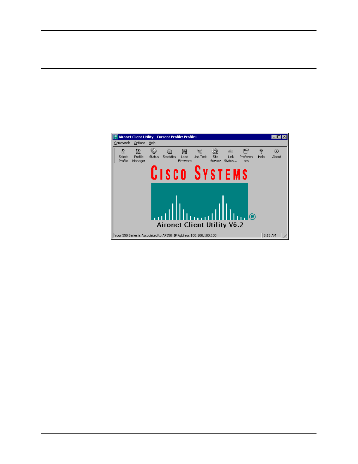
90 Cisco Radio
Cisco Radio
Configuration
Note: For more information on configuring the Cisco radio, select the “Help” item from the
menu bar or click on the “Help” icon. For details on ACU features not described in this
section, please refer to the online help.
To access the configuration utility, select Programs|Cisco Aironet|Aironet Client Utility (ACU)
from the Microsoft Windows Start menu.
Figure 5-1 Cisco Aironet Client Utility
If profiles have already been created, a profile can be selected by clicking on the Select Profile
icon.
VX5 Reference Guide E-EQ-VX5RG-A
 Loading...