

Page 1
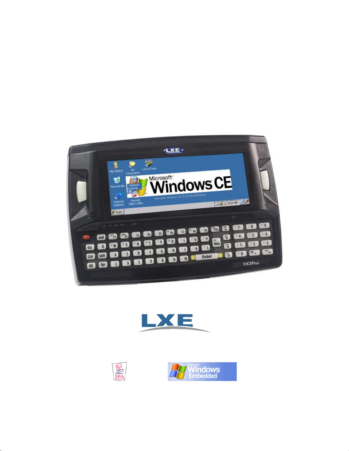
VX3Plus User’s Guide
Copyright © September 2008 by LXE Inc.
All Rights Reserved
E-EQ-VX3PLUSOGWW-B
Page 2

LANGUAGE: ENGLISH
Notices
Notice:
LXE Inc. reserves the right to make improvements or changes in the products described in this manual at any time
without notice. While reasonable efforts have been made in the preparation of this document to assure its
accuracy, LXE assumes no liability resulting from any errors or omissions in this document, or from the use of the
information contained herein. Further, LXE Incorporated, reserves the right to revise this publication and to make
changes to it from time to time without any obligation to notify any person or organization of such revision or
changes.
Copyright Notice:
This manual is copyrighted. All rights are reserved. This document may not, in whole or in part, be copied,
photocopied, reproduced, translated or reduced to any electronic medium or machine-readable form without prior
consent, in writing, from LXE Inc.
Copyright © 2008 by LXE Inc. An EMS Technologies Company.
125 Technology Parkway, Norcross, GA 30092 U.S.A. (770) 447-4224
Trademarks:
LXE® is a registered trademark of LXE Inc. RFTerm® is a registered trademark of EMS Technologies, Norcross, GA.
Microsoft, Windows and the Windows logo are registered trademarks of Microsoft Corporation in the United States and/or
other countries.
Java® and Java-based trademarks and logos are trademarks or registered trademarks of Sun Microsystems, Inc. in the U.S. or
other countries, and are used under license.
Intel and Intel XScale are trademarks or registered trademarks of Intel Corporation or its subsidiaries in the United States and
other countries.
RAM® and RAM Mount™ are both trademarks of National Products Inc., 1205 S. Orr Street, Seattle, WA 98108.
Summit Data Communications, Inc. Summit Data Communications, the Summit logo, and “The Pinnacle of Performance” are
trademarks of Summit Data Communications, Inc. All rights reserved.
The Bluetooth® word mark and logos are owned by the Bluetooth SIG, Inc. and any use of such marks by LXE, Inc. is under
license.
Wavelink® and Wavelink Avalanche® are registered trademarks and the Wavelink logo, tagline and Avalanche MC are
trademarks of Wavelink Corporation, Kirkland, WA.
All other brand or product names are trademarks or registered trademarks of their respective companies or organizations.
When this manual is in PDF format: “Acrobat® Reader® Copyright © 2008 Adobe Systems Incorporated. All rights reserved.
Adobe®, the Adobe logo, Acrobat®, and the Acrobat logo are registered trademarks of Adobe Systems Incorporated.” applies.
The user is strongly cautioned to read Appendix B, “Regulatory Notices and Safety
!
Information”. Important safety cautions, warnings and regulatory information is contained in
Appendix B.
Important: This symbol is placed on the product to remind users to dispose of Waste Electrical
and Electronic Equipment (WEEE) appropriately, per Directive 2002-96-EC. In most areas, this
product can be recycled, reclaimed and re-used when properly discarded. Do not discard labeled
units with trash. For information about proper disposal, contact LXE through your local sales
representative, or visit www.lxe.com.
Page 3

Revision Notice
VX3Plus User’s Guide
Upgrade From Revision A to Revision B
Section Explanation
Appendix B Regulatory Notices and
Safety Information
Note: A complete revision history is included in Appendix B, “Regulatory Notices and Safety Information”.
Update approvals for 802.11 a/b/g radio.
Remove Summit Declaration of Compliance for consistency.
Page 4

Page 5

Table of Contents
THE VX3PLUS VEHICLE MOUNT COMPUTER 1
Introduction............................................................................................................... 1
Identifying the VX3Plus Computer..........................................................................................2
Document Conventions ............................................................................................................3
Environmental Specifications...................................................................................................3
VX3Plus without Touchscreen................................................................................. 4
Quick Start.................................................................................................................4
Troubleshooting........................................................................................................................5
Components.............................................................................................................. 6
Microsoft Windows CE Control Panel..................................................................... 8
The Half-Screen Display........................................................................................... 8
AppLock and the VX3Plus........................................................................................ 9
Single Application AppLock ....................................................................................................9
Multi Application AppLock .....................................................................................................9
Using the Touchscreen ...........................................................................................................9
Using the Keypad .................................................................................................................10
The QWERTY Keyboard .........................................................................................11
IBM 3270 Overlay..................................................................................................................11
IBM 5250 Overlay..................................................................................................................11
Key Functions.........................................................................................................................12
CAPS Key and CapsLock Mode ............................................................................................13
Keypad Shortcuts....................................................................................................................13
Keypress Sequences................................................................................................................
Custom Key Maps ..................................................................................................................13
LED Functions........................................................................................................................14
General Windows CE Keyboard Shortcuts ............................................................................15
Input Panel (Virtual Keyboard) ..............................................................................................
Enabling the Input Panel ......................................................................................................
Power Supply.......................................................................................................... 17
Backup Battery .......................................................................................................................17
Getting Help.............................................................................................................
13
16
16
18
Manuals and Accessories...................................................................................... 18
Manuals...................................................................................................................................
Accessories .............................................................................................................................
INSTALLATION 23
E-EQ-VX3PLUSOGWW-B VX3Plus User’s Guide
18
18
Page 6

ii Table of Contents
Install Mounting Brackets ......................................................................................23
RAM Mount System ................................................................................................ 24
Components ............................................................................................................................24
Torque Measurements ............................................................................................................24
Procedure ................................................................................................................................
Step 1 – Mount Vehicle RAM Clamp Mount ......................................................................
Mounting Dimensions.................................................................................................................... 26
25
25
Step 2 – Attach RAM Mount Ball to the VX3Plus ..............................................................27
Step 3 – Attach VX3Plus Assembly to RAM Mount...........................................................28
Completed Assembly..............................................................................................................28
Strain Relief Cable Clamps ....................................................................................29
Install Stylus Tether and Sleeve (Optional) ..........................................................30
Install/Remove Touchscreen Protective Film Optional)...................................... 30
Connect Serial Barcode Scanner .......................................................................... 31
Connect Serial Printer or PC..................................................................................33
USB-C Port .............................................................................................................. 34
USB-H Port .............................................................................................................. 35
Connect External Headset...................................................................................... 36
LXE Headsets .........................................................................................................................36
Other Headsets........................................................................................................................37
Connect Antenna .................................................................................................... 38
Connect Power Cable.............................................................................................38
External Power Supply, Optional........................................................................... 39
Vehicle 12-80VDC Power Connection ...................................................................40
OPERATION 43
Power Button........................................................................................................... 43
Power Management ................................................................................................................43
Restart Sequence.....................................................................................................................
43
Display and Touchscreen....................................................................................... 44
Set the Display Backlight Timer ............................................................................................44
Set the Display Brightness......................................................................................................44
Cleaning the Display ..............................................................................................................
Disabling the Touchscreen .....................................................................................................
45
45
Calibrating the Touchscreen...................................................................................................45
Touchscreen Protective Film ..................................................................................................45
Adjust Speaker Volume.......................................................................................... 46
Using the Keypad ...................................................................................................................46
VX3Plus User’s Guide E-EQ-VX3PLUSOGWW-B
Page 7

Table of Contents iii
Using the Touchscreen ...........................................................................................................46
Microsoft Windows CE Event Sounds...................................................................................46
Laser Barcode Scanner Warnings......................................................................... 47
Enter Data................................................................................................................ 47
Keyboard Entry.......................................................................................................................
Touchscreen Entry..................................................................................................................
48
48
Right Click ...........................................................................................................................48
Tethered Scanner Entry ..........................................................................................................49
Aiming the Barcode Scanner................................................................................................49
Distance from Label .............................................................................................................49
Successful Scan ....................................................................................................................
49
Unsuccessful Scan................................................................................................................49
Bluetooth Scanners .................................................................................................................
Voice Data ..............................................................................................................................
50
50
Bluetooth Devices...................................................................................................
51
APPENDIX A KEY MAPS 53
The VX3Plus Keypad .............................................................................................. 53
Key Map 101-Key Equivalencies...........................................................................................53
IBM 3270 Keypad Overlay ....................................................................................................58
IBM 5250 Keypad Overlay ....................................................................................................58
APPENDIX B REGULATORY NOTICES AND SAFETY INFORMATION 59
Approvals ................................................................................................................60
Revision History...................................................................................................... 65
NDEX 67
I
E-EQ-VX3PLUSOGWW-B VX3Plus User’s Guide
Page 8

iv Table of Contents
Illustrations
Figure 1 VX3Plus Components, Top View .........................................................................................................6
Figure 2 VX3Plus Components, Front View.......................................................................................................6
Figure 3 VX3Plus Components, Back View .......................................................................................................7
Figure 4 Switchpad Menu....................................................................................................................................9
Figure 5 QWERTY Keyboard Standard Overlay ..............................................................................................11
Figure 6 QWERTY Keyboard with IBM 3270 Overlay....................................................................................11
Figure 7 QWERTY Keyboard with IBM 5250 Overlay....................................................................................11
Figure 8 LED Functions.....................................................................................................................................14
Figure 9 Virtual Keyboard .................................................................................................................................16
Figure 10 RAM Clamp Mount Components......................................................................................................25
Figure 11 Assembled RAM Clamp Mount........................................................................................................25
Figure 12 RAM Clamp Mount - Mounting Dimensions (Not To Scale)...........................................................26
Figure 13 Attach RAM Mount to VX3Plus.......................................................................................................27
Figure 14 RAM Assembly .................................................................................................................................28
Figure 15 Completed RAM Mount Assembly...................................................................................................28
Figure 16 Strain Relief Cable Clamps ...............................................................................................................29
Figure 17 Slide Clamp Over Cable....................................................................................................................29
Figure 18 Connect Serial Scanner Cable ...........................................................................................................31
Figure 19 VX3Plus with Generic Barcode Scanner Attached ...........................................................................32
Figure 20 Generic Barcode Scanner ..................................................................................................................32
Figure 21 Connect Serial Cable to COM3 .........................................................................................................33
Figure 22 Connect USB-C Cable....................................................................................................................... 34
Figure 23 Connect USB-H Cable ......................................................................................................................35
Figure 24 Connect External Headset .................................................................................................................36
Figure 25 Headset Adapter Cable Components.................................................................................................36
Figure 26 Headset Quick Disconnect Connector...............................................................................................37
Figure 27 Connect Power Cable to VX3Plus.....................................................................................................38
Figure 28 Optional Power Configuration ..........................................................................................................39
Figure 29 Vehicle Power Connection Cable (Fuse Not Shown)........................................................................40
Figure 30 Connecting the Power Cable to the Vehicle......................................................................................40
Figure 31 Vehicle Connection Wiring Color Codes..........................................................................................41
Figure 32 Location of the Power (PWR) Button ...............................................................................................43
Figure 33 Touchscreen Calibration, Calibration Targets...................................................................................45
Figure 34 Caution Labels Class II Scanner........................................................................................................47
Figure 35 Caution Labels Class IIIA Scanner ...................................................................................................47
Figure 36 Scan Beam.........................................................................................................................................49
Figure 37 VX3Plus QWERTY Keyboard..........................................................................................................53
Figure 38 IBM 3270 Specific Keypad ...............................................................................................................58
Figure 39 IBM 5250 Specific Keypad ...............................................................................................................58
VX3Plus User’s Guide E-EQ-VX3PLUSOGWW-B
Page 9

Introduction
The VX3Plus Vehicle Mount Computer
The VX3Plus Vehicle Mount Computer (VMC) is a rugged, vehicle-mounted, Microsoft®
Windows
®
CE equipped computer. The VX3Plus is capable of wireless data communications
from a fork-lift truck or any properly configured vehicle. The unit uses an 802.11radio for
wireless data communications.
The mobile device is horizontally oriented and features backlighting for the display. The touchscreen display supports graphic features and Windows CE icons that the Windows CE operating
system supports. The keys on the keypad are constructed of a phosphorescent material that can
easily be seen in dimly lighted areas.
The VX3Plus provides the power and functionality of a desktop computer in a vehicle mounted
unit, with a wide range of options:
®
• 400MHz Intel
PXA255 CPU
• Windows 5.0 Operating System
• An active transmissive display optimized for indoor viewing, or an active
transflecive display optimized for outdoor viewing.
• Wireless LAN radios with internal antenna or external remote mount antenna
• USB Client port
• Available touch screen protective film
• Available Bluetooth
• Available RAM Mount
®
module supports LXE Bluetooth printers and scanners.
TM
Note: The “VX3Plus Reference Guide” contains VX3Plus technical information and advanced
functions.
E-EQ-VX3PLUSOGWW-B VX3Plus User’s Guide
Page 10

2 Introduction
Identifying the VX3Plus Computer
VX3Plus
The VX3Plus is identified by the “VX3Plus” logo located at the bottom right of the keypad.
The VX3Plus is covered in this document and the VX3Plus Reference Guide.
VX3X
The VX3X is identified by the “VX3X” logo located above the keypad.
The VX3X is not covered in this document. Please refer to the VX3X User’s Guide and the VX3X
Reference Guide for information on the VX3X.
VX3Plus User’s Guide E-EQ-VX3PLUSOGWW-B
Page 11
Introduction 3
Document Conventions
This reference guide uses the following document conventions:
ALL CAPS All caps are used to represent disk directories, file names, and application
names.
Menu|Choice Rather than use the phrase “choose the Save command from the File menu”,
this manual uses the convention “choose File|Save”.
“Quotes” Indicates the title of a book, chapter or a section within a chapter (for
example, “Document Conventions”).
< > Indicates a key on the keyboard (for example, <Enter> ).
ATTENTION
!
Note: Keyword that indicates immediately relevant information.
Caution
!
WARNING
!
DANGER
!
Indicates a reference to other documentation.
Differences in operation or commands due to radio type.
Keyword that indicates vital or pivotal information to follow.
Attention symbol that indicates vital or pivotal information to follow. Also,
when marked on product, means to refer to the manual or operator’s guide.
International fuse replacement symbol. When marked on the product, the
label includes fuse ratings in volts (v) and amperes (a) for the product.
Keyword that indicates a potentially hazardous situation, which, if not
avoided, may result in minor or moderate injury.
Keyword that indicates a potentially hazardous situation, which, if not
avoided, could result in death or serious injury.
Keyword that indicates an imminent hazardous situation, which, if not
avoided, will result in death or serious injury.
Environmental Specifications
Operating Temperature
Storage Temperature -22°F to 158°F (-30°C to 70°C) [non-condensing]
Operating Humidity 5% to 95% non-condensing at 104°F (40°C)
Vibration Based on MIL Std 810D
ESD 8 kV air, 4kV contact
Shock 75G, 5ms duration, 100 shock impacts
Bluetooth Range 32.8 feet (10 meters) Direct line of sight only.
14°F to 122°F (-10°C to 50°C) [non-condensing]
E-EQ-VX3PLUSOGWW-B VX3Plus User’s Guide
Page 12

4 VX3Plus without Touchscreen
VX3Plus without Touchscreen
If a VX3Plus is not equipped with a touchscreen of if your system administrator has disabled the
touchscreen, please see the Keypad Shortcuts section, later in this manual, for helpful keypress
sequences.
Your system administrator may need to use LXEConnect to configure the VX3Plus. Complete
details on using LXEConnect to configure theVX3Plus are in the VX3Plus Reference Guide.
Quick Start
This section’s instructions are based on the assumption that your new system is pre-configured
and requires only accessory installation and a power source.
Use this guide as you would any other source book -- reading portions to learn about the
VX3Plus, and then referring to it when you need more information about a particular subject. This
guide takes you through installation and operation of the LXE VX3Plus.
In general, the sequence of events is:
1. Install RAM ball on back of VX3Plus. Install Vehicle Mounting Bracket on vehicle
and secure VX3Plus in Mounting Bracket Assembly (see “Installation”, later in this
manual).
2. Connect power cable to the VX3Plus. If using DC power, please refer to “Vehicle
12-80VDC Power Connection”, later in this manual, for instructions, warnings and
fuse information.
3. Connect accessories to VX3Plus, e.g. scanner, etc.
4. Secure all cables to the VX3Plus with the Strain Relief Cable Clamps.
5. Turn the VX3Plus on.
6. When instructed, calibrate the touchscreen.
7. The screen may appear white while applications and drivers are loading. When
complete, set Date and Time (see the “VX3Plus Reference Guide”).
8. Configure radio (see the “VX3Plus Reference Guide”).
9. Warmboot to ensure all registry settings are saved.
10. Device is ready for use.
The VX3Plus should be mounted in an area in the vehicle where it:
• Does not obstruct the vehicle driver’s vision or safe vehicle operation.
• Can be easily accessed by anyone seated in the driver’s seat.
!
If your VX3Plus has AppLock installed, please contact your system
administrator for setup and processing information.
AppLock is configured by an administrator to limit general users to only certain
programs.
VX3Plus User’s Guide E-EQ-VX3PLUSOGWW-B
Page 13

Quick Start 5
Troubleshooting
Can’t calibrate the touch
screen, change the date/time or
adjust the volume.
RFterm opens and runs upon
each cold reset and warm reset.
The VX3Plus seems to lockup
as soon as it is warm booted.
AppLock is installed and running on the mobile device.
AppLock restricts User access to running programs. Changes
or modifications require Administrator access.
Refer to AppLock in the VX3Plus Reference Guide for setup
and processing information.
Tap File | Exit to close the RFTerm application.
There may be small delays while the wireless client connects to
the network, authorization for Voxware-enabled applications
complete, Wavelink Avalanche management of the VX3Plus
startup completes, and Bluetooth relationships establish or reestablish.
E-EQ-VX3PLUSOGWW-B VX3Plus User’s Guide
Page 14
6 Components
Components
RS-232
21
3
USB-C
4
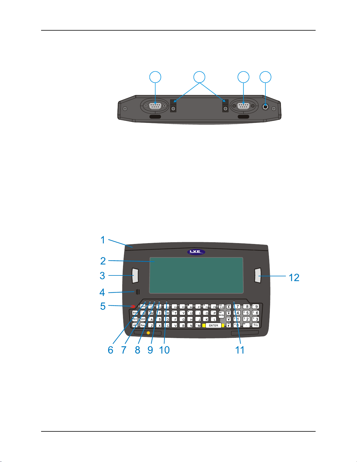
Figure 1 VX3Plus Components, Top View
1 Left Port 4 Audio or Antenna Connector
2 Strain Relief Clamps (Audio Connector shown)
3 Right Port
The following combinations are offered for the VX3Plus Endcap
Left Port Right Port
COM3 (RS-232) USB-Client (USB-C)
COM3 (RS-232) COM1 (RS-232)
USB-Host (USB-H) COM1 (RS-232)
USB-Host (USB-H) USB-Client (USB-C)
VX3Plus
Figure 2 VX3Plus Components, Front View
1 Endcap 7 Alt LED
2 Display 8 Ctrl LED
3 Programmable Key 9 Shift LED
4 Beeper 10 Caps LED
5 On/Off Button 11 Status LED
nd
6 2
LED 12 Programmable Key
VX3Plus User’s Guide E-EQ-VX3PLUSOGWW-B
Page 15
Components 7
1
2
3
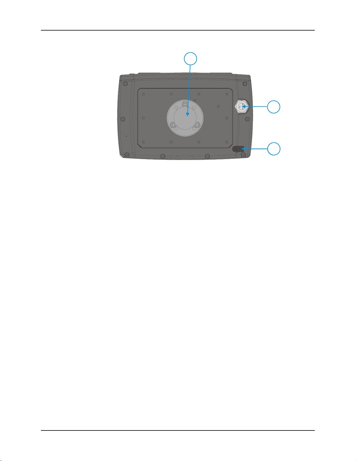
Figure 3 VX3Plus Components, Back View
1 RAM Ball
2 Power Connector
3 Strain Relief Clamp
Note: The RAM ball shown above is shipped unattached. The installer must assemble the RAM
ball to the back of the VX3Plus. See “Installation” later in this manual for details.
E-EQ-VX3PLUSOGWW-B VX3Plus User’s Guide
Page 16

8 Microsoft Windows CE Control Panel
Microsoft Windows CE Control Panel
The Microsoft Windows CE Control Panel provides standard Windows CE options for
configuring the VX3Plus, such as:
• Sounds and volume control
• Display configuration (including backlight power management)
Please consult your System Administrator or refer to commercially available
Microsoft Windows CE user guides or the on-line Help application for these standard
configuration options.
The Half-Screen Display
The VX3Plus has a half screen LCD color display capable of supporting VGA graphics mode.
The resolution is 640 x 240 pixels. The display type is either:
• An active transmissive display optimized for indoor viewing, or
• An active transflecive display optimized for outdoor viewing. A VX3Plus with this
display includes a “sun” logo to the bottom left of the keypad.
VX3Plus User’s Guide E-EQ-VX3PLUSOGWW-B
Page 17
AppLock and the VX3Plus 9
AppLock and the VX3Plus
AppLock may be installed and running on the mobile device. AppLock restricts access to
programs and the Windows CE Control Panel. Please contact your system administrator for
details.
Single Application AppLock
Single application AppLock restricts a user to one application. The user is unable to exit the
application (or if the application exits, it immediately restarts).
Note: Single application AppLock is obsolete. Please contact your LXE representative if you
desire to upgrade to multi application AppLock.
Multi Application AppLock
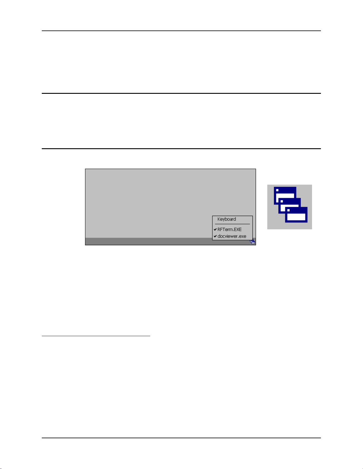
A checkmark indicates applications currently active or available for Launching by the user. When
Keyboard is selected, the VX3Plus default input method (Input Panel, Transcriber, or custom
input method) is activated.
Note: If “Keyboard” is not present in the window, an older version of AppLock is installed.
Please contact your LXE representative for upgrade information, if desired.
Using the Touchscreen
Note: The touch screen must be enabled.
When the mobile device enters end-user mode, a Switchpad icon (it looks like three tiny windows
one above the other) is displayed in the taskbar. The taskbar is always visible on top of the
application in focus.
When the user taps the Switchpad icon, a menu is displayed showing the applications available to
the user. The user can tap an application name in the popup menu and the selected application is
brought to the foreground. The previous application continues to run in the background. Stylus
taps affect the application in focus only. When the user needs to use the Input Panel, they tap the
Keyboard option. Input Panel taps affect the application in focus only.
Switchpad Menu
Figure 4 Switchpad Menu
Switchpad Icon in
Taskbar
E-EQ-VX3PLUSOGWW-B VX3Plus User’s Guide
Page 18

10 AppLock and the VX3Plus
The figure shown above is an example and is shown only to aid in describing how the user can
switch between applications using a stylus.
Using the Keypad
One switch key sequence (or hotkey) is defined by the administrator for the end-user to use when
switching between locked applications. This is known as the Activation key. When the switch
key sequence is pressed on the keypad, the next application in the AppLock configuration is
moved to the foreground and the previous application moves to the background. The previous
application continues to run in the background. End-user key presses affect the application in
focus only.
See the VX3Plus Reference Guide for AppLock setup instruction.
VX3Plus User’s Guide E-EQ-VX3PLUSOGWW-B
Page 19
The QWERTY Keyboard 11
The QWERTY Keyboard
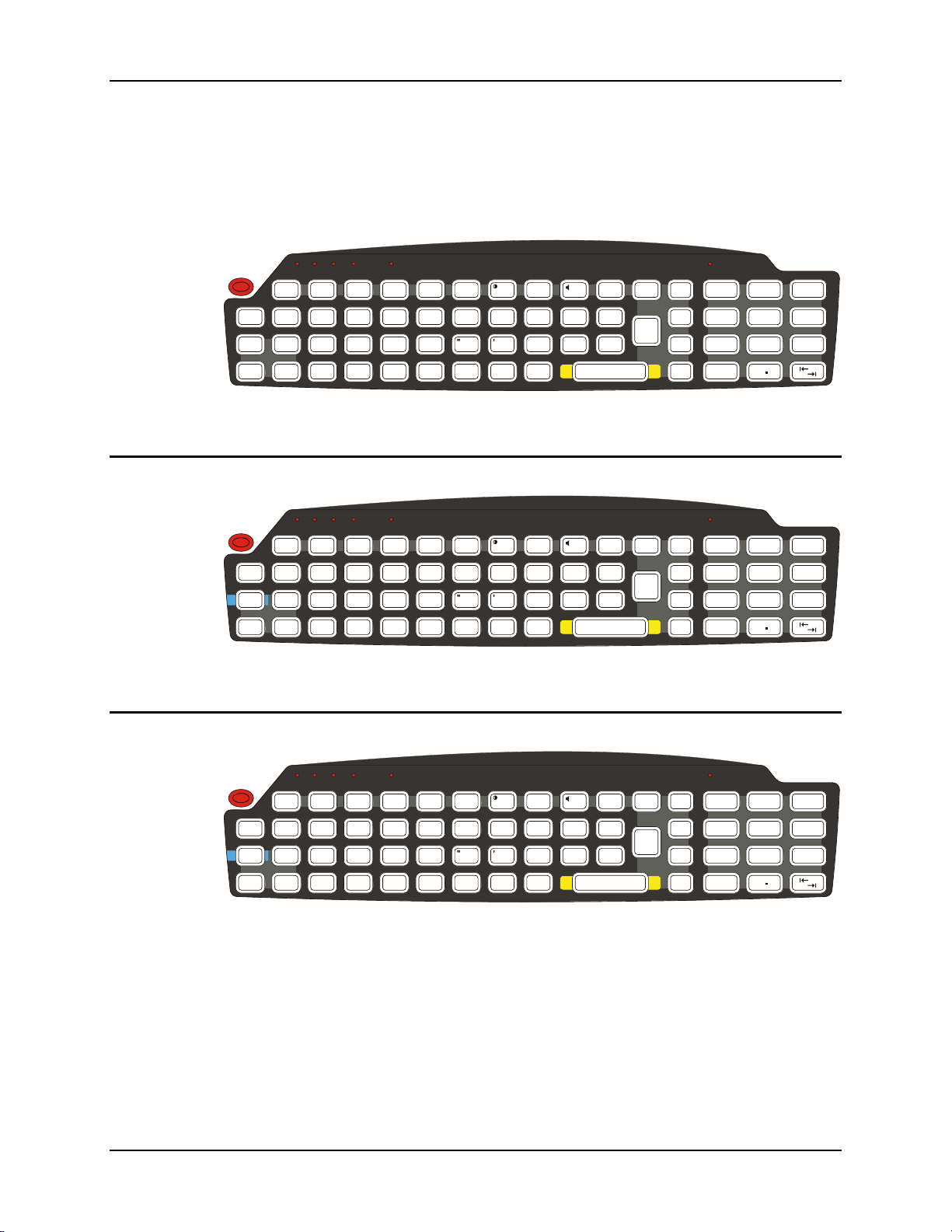
The VX3Plus has a QWERTY keyboard, available with a standard ANSI overlay, an IBM 3270
overlay or an IBM 5250 overlay. These keyboards have 101 keyboard functions, including a
numeric keypad. Please refer to Appendix A, “Key Maps”, for keypress combinations.
ALT
CTRL SHFT CAPS STAT
2nd
Esc
Ctrl
Alt
IBM 3270 Overlay
Esc
Ctrl
Alt
IBM 5250 Overlay
2nd
!
Shft
Spc
2nd
!
Shft
Spc
Q
2nd
Q
CAPS
Break
F1 F2
#
@
WERTY
|\
ASDFGH
ZXCVBNM
F3
%
$
:; ,
F5 F6
F4
^
~
F7
*
&
U
_
`
F8 F9 F10
()
IO P
.
J
KL
?
Enter
BkLt
Ins
BkSp
Figure 5 QWERTY Keyboard Standard Overlay
ALT
CTRL SHFT CAPS STAT
PA1 PA2 PA3
CAPS
Break
F1 F2
#
@
WERTY
Attn
|\
ASDFGH
ZXCVBNM
F3
Rst
%
$
SysReq
Del
:; ,
Clr
F5 F6
F4
^
&
~
`
F7
*
U
NL
_
F8 F9 F10
Ins
()
IO P
.
J
KL
?
Enter
BkLt
Ins
BkSp
E - Inp
Figure 6 QWERTY Keyboard with IBM 3270 Overlay
PgUp
/
789
PgDn
=
4
Home
[]
1
End
<
0
PgUp
/
789
PgDn
=
4
Home
[]
1
End
<
0
-
+
{}
5
6
>
3
2
Del
-
+
{}
5
6
>
3
2
Del
ALT
CTRL SHFT CAPS STAT
2nd
BkLt
Ins
BkSp
E - Inp
PgUp
/
789
PgDn
=
4
Home
[]
1
End
<
0
-
+
{}
5
6
>
3
2
Del
Esc
Ctrl
Alt
2nd
!
Shft
Spc
Q
CAPS
Break
F1 F2
#
@
WERTY
Attn
|\
ASDFGH
ZXCVBNM
F3
%
$
SysReq
Del
:; ,
Clr
F5 F6
F4
^
&
~
`
F7
Dup
*
U
NL
_
F8 F9 F10
Ins
()
IO P
.
J
Fld -
Fld +
?
KL
Enter
Figure 7 QWERTY Keyboard with IBM 5250 Overlay
Note: Press the <CTRL> + <Enter> keys to initiate the IBM 5250 Field Exit Function.
E-EQ-VX3PLUSOGWW-B VX3Plus User’s Guide
Page 20

12 The QWERTY Keyboard
Key Functions
Key Function
Programmable
Enter
2nd
Ctrl
For information on programming these keys, please refer to the “VX3Plus
Reference Guide”.
By default, these keys function as Enter keys, except for IBM 5250
configurations where the left button is configured as “Field Exit”.
The Enter key is used to confirm a form entry or to transmit information.
How it is used is determined by the application running on the computer.
nd
key is used to activate the 2nd functions of the keypad. Printed on
The 2
many keys at the upper left corner are small characters that represent the 2
function of that key. Using the 2
Note that the 2
need to use the 2
nd
key only stays active for one keystroke. Each time you
nd
function you must press the 2nd key. To cancel a 2nd
function before pressing another key, press the 2
When the 2
nd
function is active, the 2nd LED illuminates.
nd
key activates the second key function.
nd
key again.
The Ctrl key enables the control functions of the keypad. This function is
similar to a regular keyboard’s Control key. Note that the Ctrl key only
stays active for one keystroke. Each time you need to use a Ctrl function,
you need to press the Ctrl key before pressing the desired key.
When the Ctrl function is active, the Ctrl LED illuminates.
nd
Alt
Shft
Spc
The Alt key enables the alternate functions of the keypad. This function is
similar to a regular keyboard’s Alt key. Note that the Alt key only stays
active for one keystroke. Each time you need to use an alternate function,
you need to press the Alt key before pressing the desired key.
When the Alt function is active, the Alt LED illuminates.
The Shft key enables the shifted functions of the keypad. This function is
similar to a regular keyboard’s Shift key. Note that the Shift key only stays
active for one keystroke. Each time you need to use a Shifted function, you
need to press the Shft key before pressing the desired key. When the Shft
function is active, the Shft LED illuminates.
When the Shft key is pressed the next key is determined by the major key
legends, i.e., the alpha keys display lower case letters – when CAPS is On
alpha characters are capitalized. For example, when CAPS is on and the
Shft key and the G key are pressed, a lower case g is displayed.
The Spc key adds a space to the line of data on the display. This function is
similar to a regular keyboard’s Spacebar. Note that the Spc key only stays
active for one keystroke.
VX3Plus User’s Guide E-EQ-VX3PLUSOGWW-B
Page 21

The QWERTY Keyboard 13
CAPS Key and CapsLock Mode
This function is similar to a regular keyboard’s CapsLock key. Note that the CAPS mode stays
active until the CAPS key sequence is pressed again. Each time you need to use a Caps function,
you need to press the CAPS key sequence first. To cancel a Caps function press the CAPS key
sequence again. When the Caps mode is active, the Caps LED illuminates.
nd
The CAPS key sequence is 2
• No CAPS AND No Shift keypress – result is a lowercase letter.
• CAPS OR Shift – result is an uppercase letter.
• CAPS AND Shift keypress – result is a lowercase letter.
For information on preserving Caps configuration after a reboot, please see refer to the “VX3Plus
Reference Guide”.
+ F1.
Keypad Shortcuts
Use keyboard shortcuts instead of the stylus:
• Press Tab and an Arrow key to select a file.
• Press Shift and an Arrow key to select several files.
• Once you’ve selected a file, press Alt then press Enter to open its Properties dialog.
• Press 2nd then press numeric dot to delete a file.
• To force the Start menu to display, press Ctrl then press Esc.
Keypress Sequences
See Appendix A for all key press sequences.
Custom Key Maps
The System Administrator can create custom key maps. Details are in the VX3Plus Reference
Guide.
E-EQ-VX3PLUSOGWW-B VX3Plus User’s Guide
Page 22
14 The QWERTY Keyboard
LED Functions
ALT
CTRL SHFT CAPS STAT
2nd
CAPS
2nd
Break
F1 F2
F3
F5 F6
F4
F7
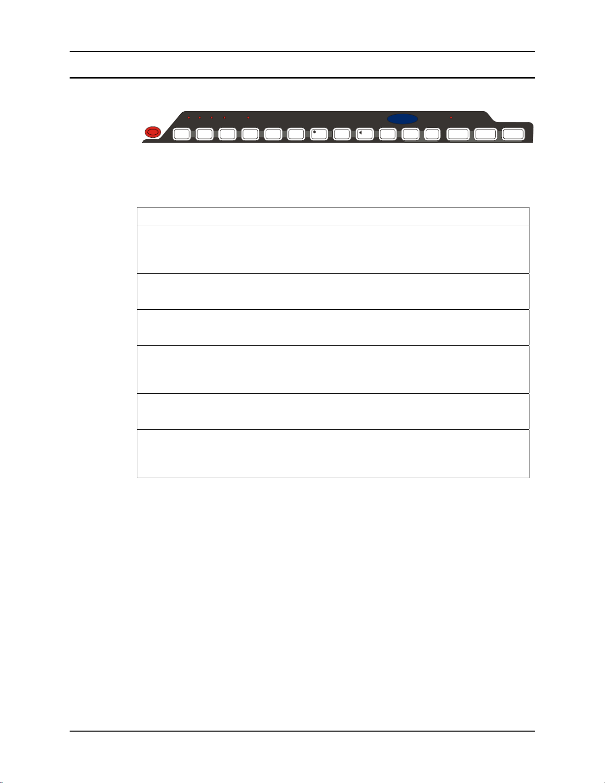
Figure 8 LED Functions
Across the top of the keypad are LEDs that provide visual cues to current computer operation.
When the LED is not illuminated, the function is inactive.
LED When illuminated ...
2nd
The next keypress is a 2
nd
keypress.
• Amber when on
• Blinks amber during configuration key sequence.
VX3X
F8 F9 F10
BkLt
PgUp
/
789
-
+
ALT
The next keypress is an ALT keypress.
• Amber when on and unlit when off.
CTRL
The next keypress is a CTRL keypress.
• Amber when on and unlit when off.
SHFT
The next letter is the uppercase letter on alpha keys and the shifted character on the
numeric keypad keys.
• Amber when on and unlit when off.
CAPS
Uppercase letters are active until the CAPS key sequence is pressed again.
• Amber when on and unlit when off.
STAT
Status Indicator.
• Amber when device is booting up.
• Blinking Green when display Suspend state begins.
VX3Plus User’s Guide E-EQ-VX3PLUSOGWW-B
Page 23

The QWERTY Keyboard 15
General Windows CE Keyboard Shortcuts
Use the keyboard shortcuts in the chart below to navigate with the VX3Plus keyboard. These are
standard keyboard shortcuts for Windows CE applications.
Press these keys … To …
CTRL + C Copy
CTRL + X Cut
CTRL + V Paste
CTRL + Z Undo
DELETE Delete
SHIFT with any of the arrow keys
CTRL+A Select all.
ALT+ESC Cycle through items in the order they were opened.
CTRL+ESC Display the Start menu.
ALT+Underlined letter in a menu
name
Underlined letter in a command
name on an open menu
ESC Cancel the current task.
The touchscreen provides equivalent functionality to a mouse:
• A touch on the touchscreen is equivalent to a left mouse click.
• Many items can be moved by the “drag and drop” method, touching the desired item,
moving the stylus across the screen and releasing the stylus in the desired location.
• A double stylus tap is equivalent to a double click.
• A touch and hold is equivalent to a right mouse click.
Select more than one item in a window or on the
desktop, or select text within a document.
Display the corresponding menu.
Carry out the corresponding command.
E-EQ-VX3PLUSOGWW-B VX3Plus User’s Guide
Page 24
16 The QWERTY Keyboard
Input Panel (Virtual Keyboard)
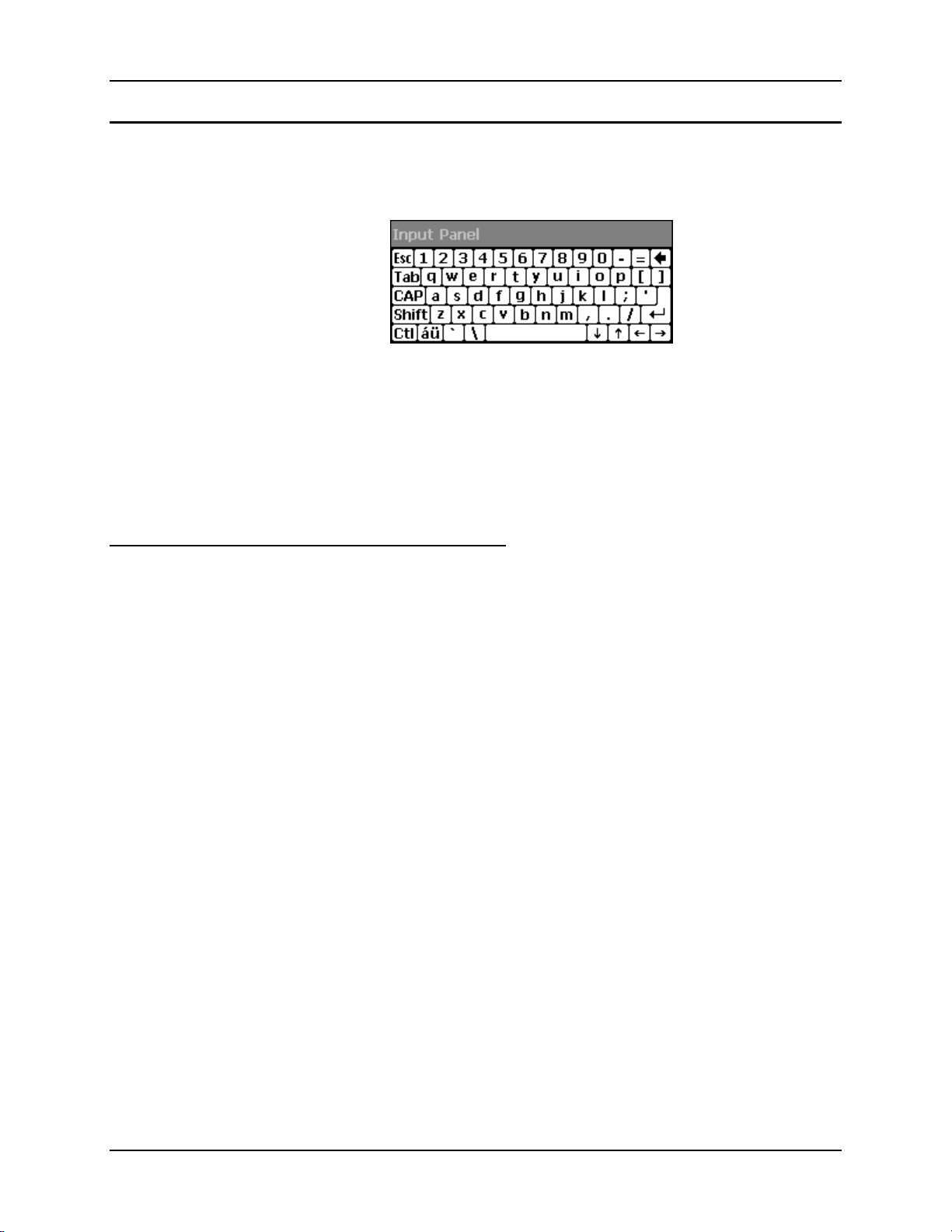
The Input Panel may be enabled via the Input Panel icon in the Windows CE Control Panel. The
Input Panel can be displayed as a large or small keyboard.
Figure 9 Virtual Keyboard
Virtual keyboards display the actual character a keypress results in. For example, pressing the
<Shift> key on the virtual keyboard toggles the characters displayed on the keys between upper
and lower case. The <áü> key toggles the keys between standard and international symbols. The
<Shift> and <áü> keys can be used in combination for capitalized international characters.
Note: When the virtual keyboard is displayed, the physical keyboard is still active. Therefore it
is possible to input data from both keyboards.
Enabling the Input Panel
The Input Panel is disabled by default. Please see the “VX3Plus Reference Guide” for details on
enabling the Input Panel
VX3Plus User’s Guide E-EQ-VX3PLUSOGWW-B
Page 25
Power Supply 17
Power Supply
Vehicle power input for the VX3Plus is 12V to 80V DC and is accepted without the need to
perform any manual adjustments within the VX3Plus. See the section titled “Installation”, subsection titled “Vehicle 12-80V DC Direct Connection”.
If 12V to 80V DC power is not available – for example, in an office environment – an optional
external Input Power Supply can be used to convert AC wall power to an appropriate DC level.
See the section titled “Installation”, sub-section titled “External Power Supply”.
Backup Battery
The internal Lithium backup (coin cell) battery provides power to maintain date and time when
the VX3Plus is not powered from an external source.
Caution
!
Danger of explosion if battery is incorrectly replaced.
Replace only with the same type or equivalent type recommended by the
manufacturer.
Dispose of used batteries according to the manufacturer’s instructions.
E-EQ-VX3PLUSOGWW-B VX3Plus User’s Guide
Page 26

18 Getting Help
Getting Help
All LXE manuals are now available on one CD and they can also be viewed / downloaded
from the LXE ServicePass website on the ServicePass / Documentation page. Contact your LXE
representative to obtain the LXE Manuals CD or logon information for the ServicePass web
pages.
You can also get help from LXE by calling the telephone numbers listed on the LXE Manuals
CD, in the file titled “Contacting LXE”. This information is also available on the LXE website.
Explanations of terms and acronyms used in this guide are located in the file titled “Glossary” on
the LXE Manuals CD.
Manuals and Accessories
Manuals
The following manuals are available on the LXE Manuals CD:
• VX3Plus Reference Guide
• Contacting LXE
Accessories
• LXE Technical Glossary
The table below lists the available VX3Plus accessories.
• Where two parts numbers are listed for a given part, the part number ending in “-R”
is the RoHS compliant version.
• When only one part number is listed, the part is RoHS compliant unless otherwise
noted.
VX3Plus Brackets
Bracket, RAM Squeeze Mount, VX3Plus VX3XA001BRKTRAMSQZ
Data Cables
Cable, Null Modem, Printer/PC D9 to D25
Cable, PC, D9 to D9
(For endcaps with an RS-232 port only)
Cable, D9 to USB Type A Host
(for endcaps with a USB-H port only)
Cable, D9F to USB Client Type A
(for endcaps with a USB-C port only)
Cable, D9 to USB Type B Host
(for endcaps with a USB-H port only)
9000A053CBL6D9D25
(above part is not RoHS compliant)
9000A054CBL6D9D9
MX3XA068CBLD9USBHOST
MX3A069CBL09USBCLNT-R
MX3XA071CBLD9USBTYPB
MX3XA071CBLD9USBTYPB-R
Replacement Power Cables
Cable, Input Power, 12 FT, VX3Plus VX3XA051CBLPWR12FT
VX3Plus User’s Guide E-EQ-VX3PLUSOGWW-B
Page 27

Manuals and Accessories 19
Power Supplies
Power Supply, External, AC, W/US Power Cord VX3Plus 1300A304PSACUS
Power Supply, External, AC, No Power Cord VX3Plus 1300A303PSACWW
Adapter Cable for AC Power Supply to VX3Plus 9000A081CBLAC2VX3X
Antenna Mount Kits
Remote Mount Antenna Assembly Kit, 8 Ft Cable 9000A279ANTREMOTE8-R
Remote Mount Antenna Assembly Kit, 6 Ft Cable 9000A278ANTREMOTE6-R
Right Angle Remote Mount Antenna Assembly Kit, 6 Ft Cable 9000A280ANTREMOTE6RT
Right Angle Remote Mount Antenna Assembly Kit, 15 Ft Cable 9000A281ANTREMOT15RT
Miscellaneous
Stylus, with Tethers and Sleeves, 5 Pack 9000A507STYLUS
Protective Film, Touchscreen, 10 Pack, VX3Plus MX3XA503PROTFILM
Cover Plate, RS-232 Port MX3RA351RS232CVR
Tethered Scanners
Scanner, Powerscan, SR, 8’ Cbl, WW
Scanner, Powerscan, SR, 12’ Cbl, US
Scanner, Powerscan, SR, Low Temp, 8’ Cbl
Scanner, Powerscan, SR, Low Temp, 12’ Cbl
Scanner, Powerscan, LR, 8’ Cbl, WW
Scanner, Powerscan, LR, 12’ Cbl, US
Scanner, Powerscan, LR, Low Temp, 8’ Cbl
Scanner, Powerscan, LR, Low Temp, 12’ Cbl
Scanner, Powerscan, XLR, 8’ Cbl, WW
Scanner, Powerscan, XLR, 12’ Cbl, US
Scanner, Powerscan, XLR, Low Temp, 8’ Cbl
Scanner, Powerscan, XLR, Low Temp, 12’ Cbl
Scanner, LS3408 Fuzzy Logic SR, D9 Interface Cable, 8ft
Scanner, LS3408 Extended Range, D9 Interface Cable, 8ft 8520A326SCNRERDA9F-R
8300A326SCNRPWRSR8DA9F
8300A326SCNRPWRSR8DA9F-R
8300A327SCNRPWRSR12DA9F
(above part is not RoHS compliant)
8300A332SCNRS8D9FLT
(above part is not RoHS compliant)
8300A333SCNRS12D9FLT
(above part is not RoHS compliant)
8310A326SCNRPWRLR8DA9F
8310A326SCNRPWRLR8DA9F-R
8310A327SCNRPWRLR12DA9F
8310A327SCNRPWRLR12DA9F-R
8310A332SCNRL8D9FLT
(above part is not RoHS compliant)
8310A333SCNRL12D9FLT
(above part is not RoHS compliant)
8320A326SCNRPWRXLR8DA9F
8320A326SCNRPWRXLR8DA9F-R
8320A327SCNRPWRXLR12DA9F
(above part is not RoHS compliant)
8320A332SCNRX8D9FLT
(above part is not RoHS compliant)
8320A333SCNRX12D9FLT
(above part is not RoHS compliant)
8510A326SCNRFZYDA9F
8510A326SCNRFZYDA9F-R
E-EQ-VX3PLUSOGWW-B VX3Plus User’s Guide
Page 28

20 Manuals and Accessories
Bluetooth Scanner and Accessories
LXE Bluetooth module with laser ring scanner, battery,
two hand/wrist straps (large and small)
LXE Bluetooth module with 1D/2D imager ring scanner,
battery, two hand/wrist straps (large and small)
Li-Ion Spare Battery for LXE Bluetooth Ring Scanner
Module
8651A100BTLASERKIT
8652A100BTIMAGERKIT
8650A376BTBOHBATTERY
LXE 8-bay battery charger with US power cord 8650A377BTBOHCHGRUS
LXE single-bay charger with US wall plug 8651A379SINGLECHGRUS
PowerScan 7000BT Scanner RS-232 with pointer 8700A301SCNRBTSRI
PowerScan 7000BT Base Station, RS232, without universal
power supply.
PowerScan 7000BT Base Station Power Supply, Std US, 120V 8700A502PSACUS
PowerScan 7000BT, RS232 Cable for Base Station, DB9S, Coil,
8’
PowerScan 7000BT Battery Charger with Power Supply, Four
Station, US Std
PowerScan 7000BT Battery Pack 8700A504BATT
Bluetooth Standard Range Fuzzy Logic laser scanner
Bluetooth Auto range “LORAX” scanner
Desk Cradle, Radio/Charging, Multi-Interface
Desk Cradle, Charge Only, Mulit-Interface
Forklift Cradle, Radio/Charging, Multi-Interface
Forklift Cradle, Charge Only, Multi-Interface
US AC Power Cord
Universal Desktop Power Supply 90-264VAC
9-60VDC Forklift Power Supply
Power Cable (connects Power Supply to Forklift)
Cable Assembly, DA9F, 9 ft, Cradle to Terminal
Forklift Rugged Scanner Holder with RAM mount
8800 Spare Battery
Single slot Universal Battery Charger Adapter Cup
Single Slot Battery Charger w/International Power
Universal Battery Charger, 4 slot. Requires 4 adapter cups
Scanner Holster for Belt
Mounted take up Reel 8000A501INDREEL
Auto Sense Intellistand, Hands Free Scanning
Strap with Scanner Clip
8700A501BASERS232
8700A001CBL8DA9F
8700A503CHGR4US
8810A326SCNRBTFZ
8820A327SCNRBTER
8800A001CRADLERCMI
8800A002CRADLECMI
8800A003CRADLEVRCMI
8800A004CRADLEVCMI
8800A051POWERCORD
8800A301ACPS
8800A302DCPS
8800A052DCPWRCABLE
8500A051CBL9DA9F
8800A005STAND
8800A376BATTERY
8800A377CHGRADPTRCUP
8800A378CHGR1SLOT
8800A379CHGRBASE
8200A501HOLSRBELT
8500A505STANDSMT
9000A411SCNRSTRAP
VX3Plus User’s Guide E-EQ-VX3PLUSOGWW-B
Page 29

Manuals and Accessories 21
Voice Recognition Accessories
Headset coiled adapter cable, with quick disconnect connector to
a 2.5 mm audio jack. A headset (see below) is required
Headset, Single Band HX1A501SINGHEADSET
Headset, Dual Band HX1A502DUALHEADSET
Headset, Behind the Ear, Dual Ear HX1A503BTHHEADSET
Foam, Replacement Block, Headset HX1A504HSBLOCKFOAM
Yoke, Replacement for Dual Band Headset HX1A505DUALYOKE
Yoke, Replacement for Single Band Headset HX1A506SINGLEYOKE
Replacement Microphone Foam, Wind Screen, 10 pack HX1A508WINDSREEN10
Replacement Microphone Foam, Wind Screen, 50 pack HX1A509WINDSREEN50
Replacement Headset Foam, Ear Cover, 10 pack HX1A510FOAMEAR10
Replacement Headset Foam, Ear Cover, 50 pack HX1A511FOAMEAR
9000A076CBLHEADSET1
E-EQ-VX3PLUSOGWW-B VX3Plus User’s Guide
Page 30

22 Manuals and Accessories
VX3Plus User’s Guide E-EQ-VX3PLUSOGWW-B
Page 31

Install Mounting Brackets
Installation
Caution:
Equipment Needed: Phillips No. 1 screwdriver and a Torque wrench capable of measuring to 50
inch pounds (5.64±.56 N/m).
Note: Torquing tool is not supplied by LXE. Tools needed to attach the RAM Clamp Mount to
The VX3Plus is designed to use a RAM mount system.
Before installation begins, verify you have the applicable vehicle mounting bracket assembly
components necessary, as shown in the following figures.
This device is intended to transmit RF energy. For protection against RF exposure
to humans and in accordance with FCC rules and Industry Canada rules, this
transmitter should be installed such that a minimum separation distance of at least
20 cm (7.8 in.) is maintained between the antenna and the general population.
This device is not to be co-located with other transmitters.
the vehicle are not supplied by LXE.
E-EQ-VX3PLUSOGWW-B VX3Plus User’s Guide
Page 32
24 RAM Mount System
RAM Mount System
Components
RAM Mounting Assembly
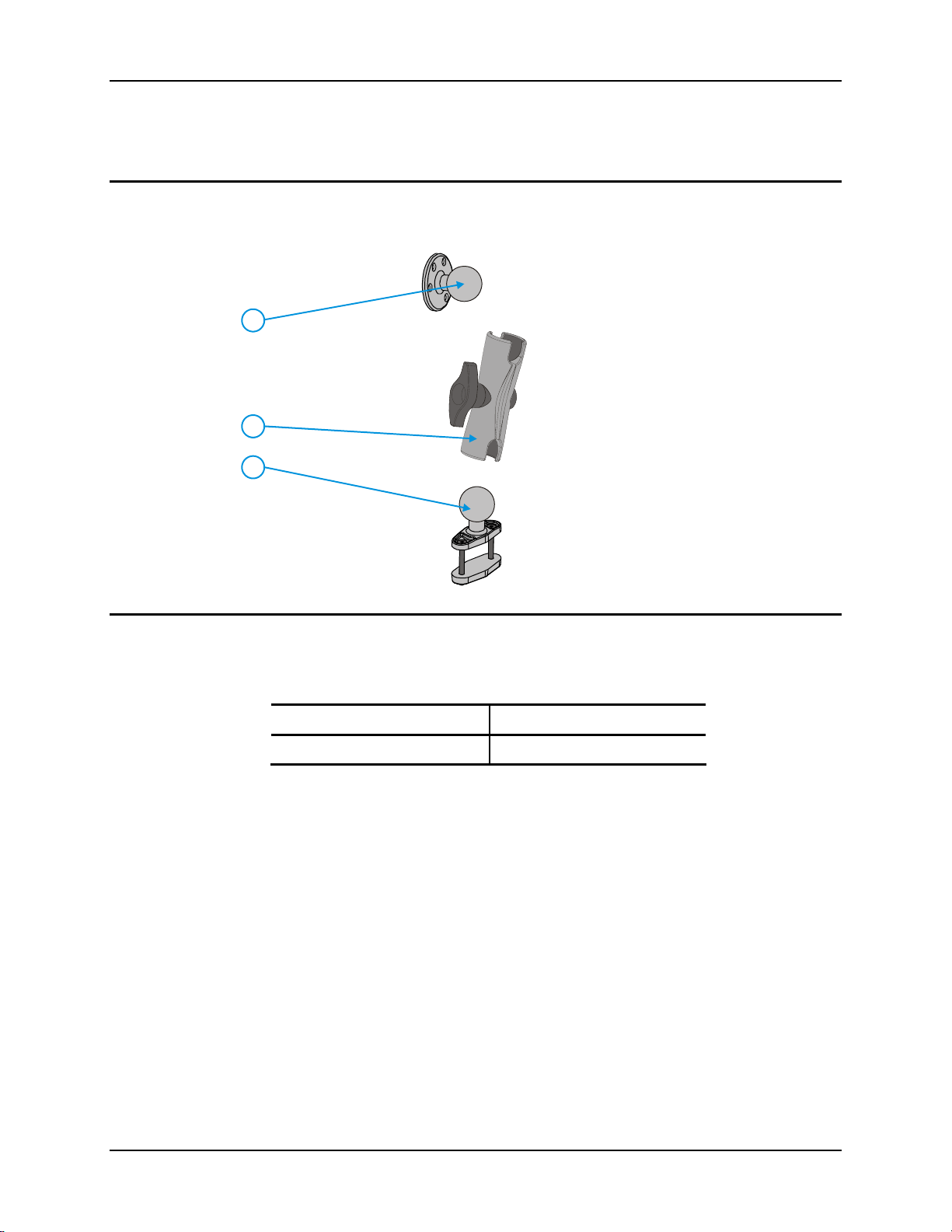
The RAM mounting assembly consists of
the following parts:
VX3Plus RAM ball (included with
1.
1
2
3
VX3Plus)
RAM arm, size C
2.
RAM clamp mount
3.
RAM Clamp Mount includes:
Upper Clamp Piece with Ball
Lower Clamp Piece
Bolts (2 each)
Nylon locking nuts (2 each)
Hardware (not shown):
4.
Lock Nuts, 10-32 (3 each)
RAM wrench
Torque Measurements
You will need a torquing tool capable of torquing to 20 inch pounds (1.10 N/m).
Torque all screws and bolts according to the following table:
For these nuts… Torque to
10-32 lock nuts 17 - 20 in/lb (0-95 - 1.10 N/m)
VX3Plus User’s Guide E-EQ-VX3PLUSOGWW-B
Page 33
RAM Mount System 25
Procedure
Step 1 – Mount Vehicle RAM Clamp Mount
1. Determine the position for mounting
the RAM clamp mount. The clamp
mount can be used on a beam (such
as on a fork lift truck) up to 2.5”
(63.5 mm) wide and approximately
2” (50.8 mm) thick. The clamp may
be attached to a thicker beam by
substituting longer bolts (not
included). Be sure to position the
RAM clamp mount to allow access
to the switches and ports on the
VX3Plus.
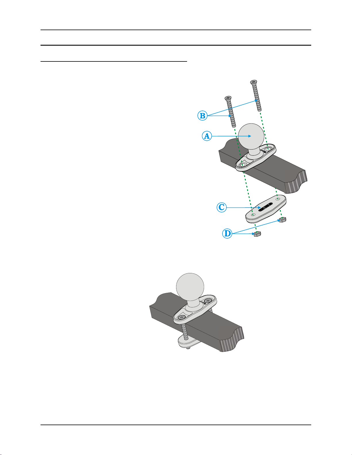
2. Position the upper clamp piece with
ball (A) on the beam. Place the bolts
(B) through the holes in the upper
clamp piece.
3. Position the lower clamp piece (C)
below the beam. Align the bolts with
the holes in the lower clamp piece.
4. Place the nylon locking nuts (D) on
the bolts and tighten the bolts.
Figure 11 Assembled RAM Clamp Mount
Figure 10 RAM Clamp Mount
Components
E-EQ-VX3PLUSOGWW-B VX3Plus User’s Guide
Page 34
26 RAM Mount System
Mounting Dimensions
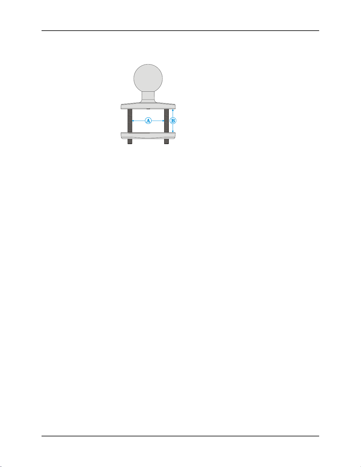
A 2.56” (65.02 mm)
B 1.84” (46.74 mm)
Varies depending on bolt length
Figure 12 RAM Clamp Mount - Mounting Dimensions (Not To Scale)
VX3Plus User’s Guide E-EQ-VX3PLUSOGWW-B
Page 35
RAM Mount System 27
Step 2 – Attach RAM Mount Ball to the VX3Plus
1. Turn the VX3Plus off before attaching the RAM mount ball.
2. Place the VX3Plus face down on a stable surface.
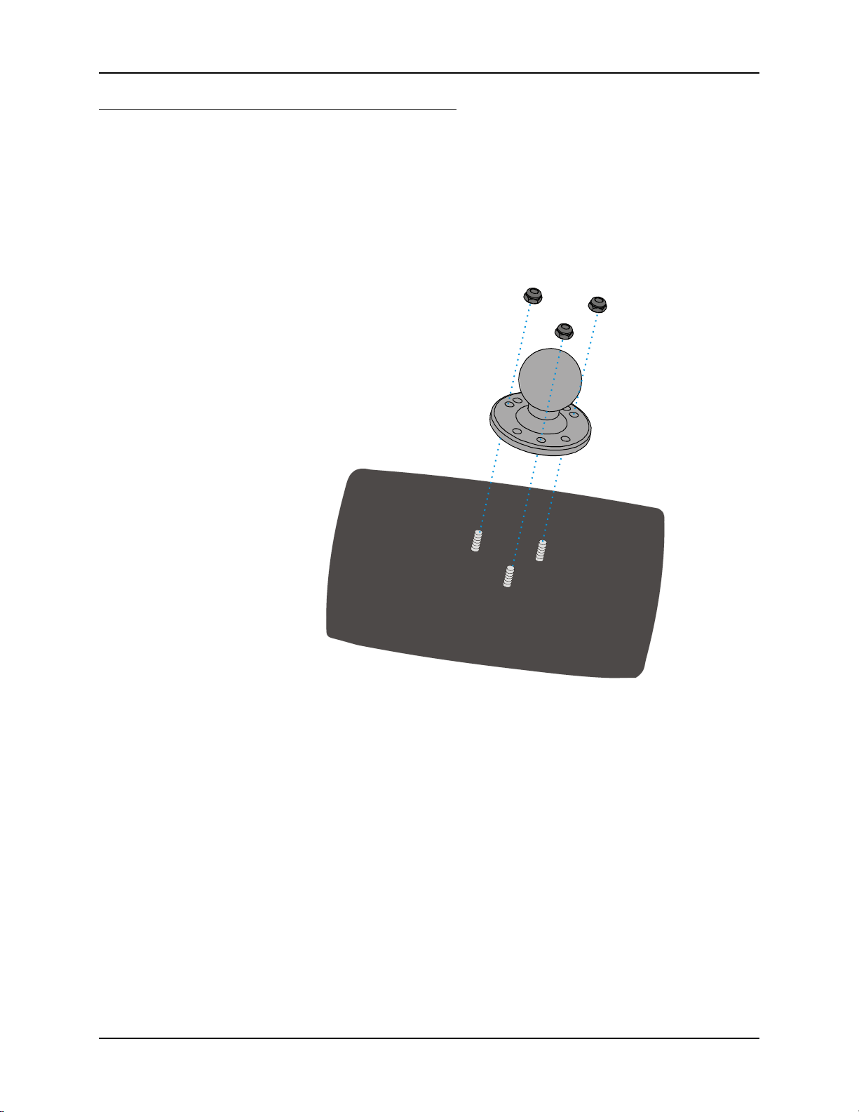
3. Position the RAM ball bracket on the rear of the VX3Plus, aligning the studs on the back
of the VX3Plus with the holes on the RAM ball mount bracket. Attach with three 10-32
lock nuts.
Figure 13 Attach RAM Mount to VX3Plus
E-EQ-VX3PLUSOGWW-B VX3Plus User’s Guide
Page 36
28 RAM Mount System
Step 3 – Attach VX3Plus Assembly to RAM Mount
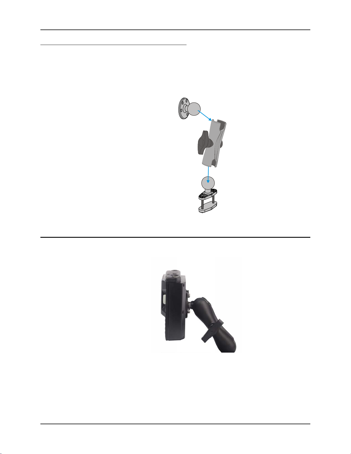
1. Slip the RAM arm over the ball on the vehicle RAM clamp mount. Insert the ball of the
RAM mount bracket into the RAM arm. Adjust the VX3Plus to the desired position and
tighten the knob on the RAM arm using the supplied RAM wrench.
Completed Assembly
Figure 14 RAM Assembly
Figure 15 Completed RAM Mount Assembly
VX3Plus User’s Guide E-EQ-VX3PLUSOGWW-B
Page 37
Strain Relief Cable Clamps 29
Strain Relief Cable Clamps
Equipment Required: Phillips screwdriver (not supplied by LXE)
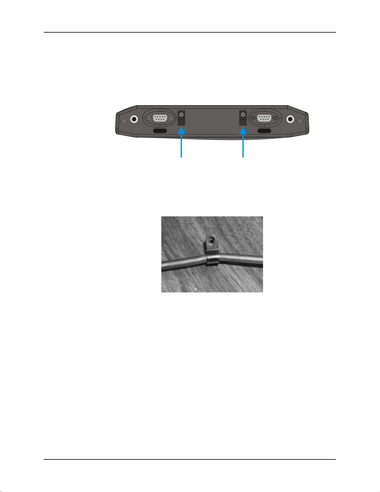
There are two strain relief cable clamps secured to the VX3Plus endcap. Use the strain relief
clamps to secure audio, power, and I/O cables attached to the VX3Plus.
RS-232
USB-C
Figure 16 Strain Relief Cable Clamps
1. Remove the strain relief clamp from the endcap by turning the screw counterclockwise. Put
the screw aside in a safe location.
2. Slide the strain relief clamp over the cable.
Figure 17 Slide Clamp Over Cable
3. Using a Phillips screwdriver and the screw that was removed, refasten the clamp holding the
cable to the endcap. Do not stretch the cable. Leave enough slack in the cable to allow it to be
connected and disconnected easily when needed.
4. Continue in this manner until all cables are secured to the endcap.
E-EQ-VX3PLUSOGWW-B VX3Plus User’s Guide
Page 38

30 Install Stylus Tether and Sleeve (Optional)
Install Stylus Tether and Sleeve (Optional)
Carefully remove the paper backing from the Stylus Clip sticky. Firmly press the sticky side of the
clip onto the mobile device and hold in place for 15 seconds. Thread the tether through the end of
the stylus and tie the ends firmly to the Stylus Clip so that the ends don’t interfere with placing the
stylus in the Stylus Clip. Place the stylus in the Stylus Clip when not in use.
An extra or replacement stylus can be ordered from LXE. See the section titled “Accessories” for
the stylus part number.
Install/Remove Touchscreen Protective Film Optional)
First, clean the display of fingerprints, lint particles, dust and smudges.
Remove the protective film from its container. Remove any protective backing from the film sheet
by lifting the backing from a corner of the film. Discard the backing.
Apply the film to the screen starting at one side and smoothing it across the display. If air bubbles
appear, raise the film slightly and continue smoothing the film across the display until it covers
the glass surface of the display.
If dust, lint or smudges are trapped between the protective film and the glass display, remove the
protective film, clean the display and apply the protective film again.
VX3Plus User’s Guide E-EQ-VX3PLUSOGWW-B
Page 39
Connect Serial Barcode Scanner 31
Connect Serial Barcode Scanner
Some endcap configurations contain a single serial port or dual serial ports. These ports are
labeled RS-232 and are configured either as COM1 or COM3. Please refer to “Components”
earlier in this manual for port identification.
Refer to the documentation received with the barcode scanner for complete
instructions. Read all warnings and caution labels.
!
Before using the scanner, read section titled “Operation”, sub- section titled “Laser
Barcode Scanner Warnings”.
Pin 9 of COM1 or COM3 (when present) may be configured to provide +5V or RI. To change
Pin 9 of the port, please refer to the “VX3Plus Reference Guide”.
Caution – Do Not Use the USB-C or USB-H Labeled Port for Tethered Scanners.
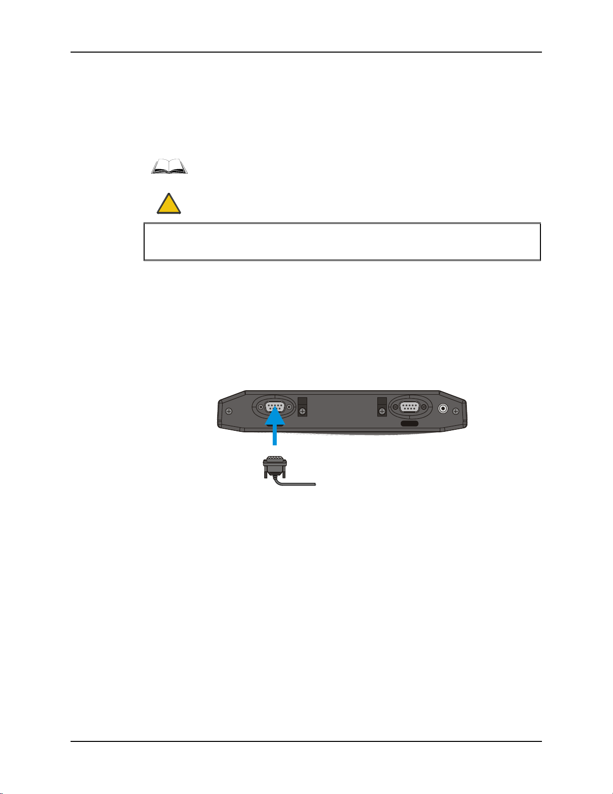
The scanner cable is attached to the connector labeled “RS-232”. The scanner receives power
from the VX3Plus.
The cable requires a nine-pin D-shell female connector for the VX3Plus.
Note: Use of a shielded cable is required to maintain FCC and CISPR22 emissions
compliance.
RS-232
USB-C
Figure 18 Connect Serial Scanner Cable
1. Power off the VX3Plus before connecting the scanner cable to the VX3Plus.
2. Seat the connector firmly over the pins and turn the thumbscrews in a clockwise
direction. Do not overtighten.
3. Use a strain relief clamp to secure the cable.
4. Press the power button to power up the VX3Plus.
E-EQ-VX3PLUSOGWW-B VX3Plus User’s Guide
Page 40
32 Connect Serial Barcode Scanner
When you have finished using the scanner, remove it from the VX3Plus and store the scanner in a
closed container or bag.
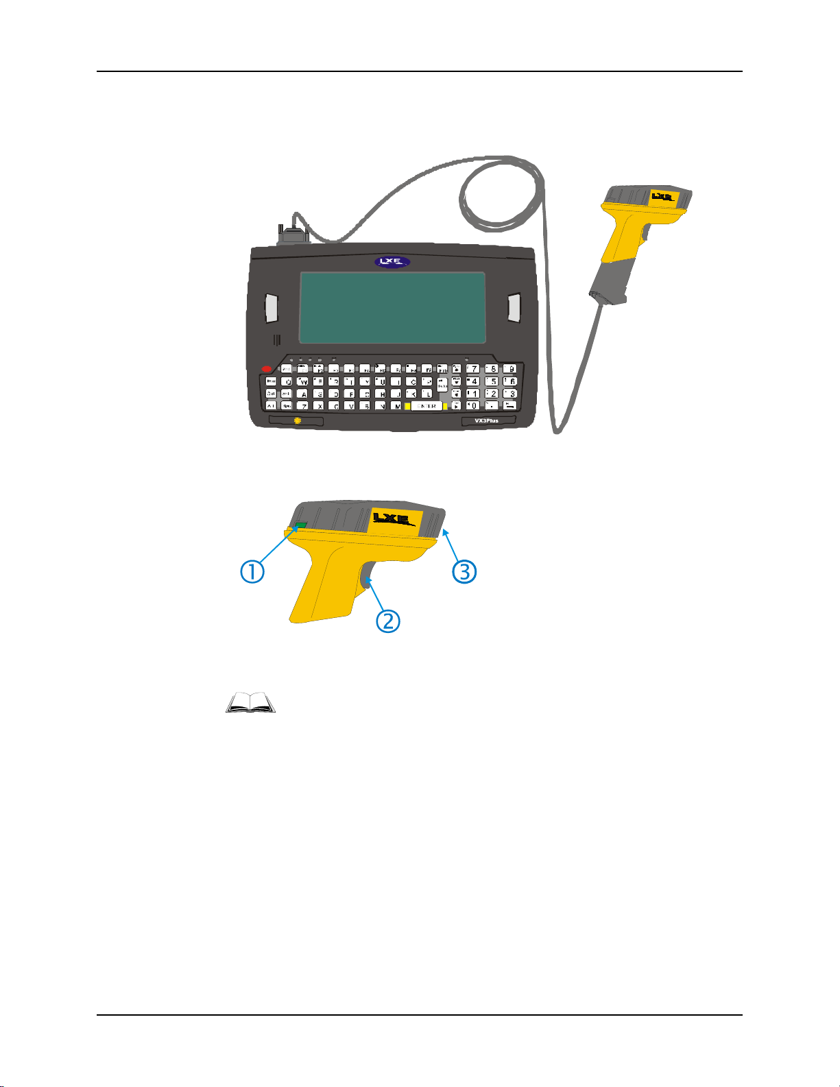
Figure 19 VX3Plus with Generic Barcode Scanner Attached
1. Good Scan LED (or equivalent)
2. Trigger
3. Laser Aperture at Front
Figure 20 Generic Barcode Scanner
Refer to the documentation received with the barcode scanner for complete
instructions.
VX3Plus User’s Guide E-EQ-VX3PLUSOGWW-B
Page 41
Connect Serial Printer or PC 33
Connect Serial Printer or PC
Some endcap configurations contain a single serial port or dual serial ports. These ports are
labeled RS-232 and are configured either as COM1 or COM3. Please refer to “Components”
earlier in this manual for port identification.
Refer to the documentation received with the printer or PC for complete
instructions.
Pin 9 of COM1 or COM3 (when present) may be configured to provide +5V or RI. To change
Pin 9 of the port, please refer to the “VX3Plus Reference Guide”.
Caution – Do Not Use the USB-C or USB-H Labeled Port for PC serial cables or printers.
The printer or PC cable requires a nine-pin D-shell female connector for the VX3Plus.
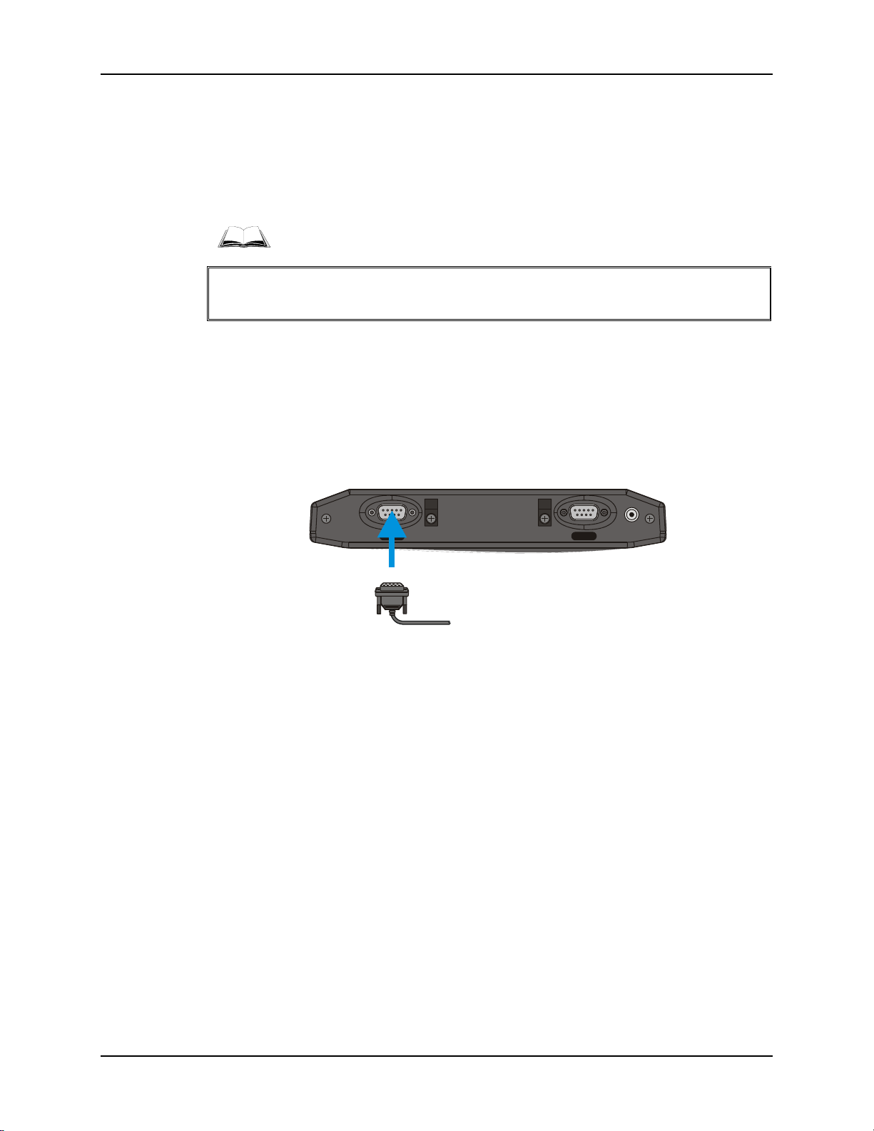
The printer or PC cable is attached to the connector labeled “RS-232”.
Note: Use of a shielded cable is required to maintain FCC and CISPR22 emissions
compliance.
RS-232
USB-C
Figure 21 Connect Serial Cable to COM3
1. Power off the VX3Plus before connecting the cable to the VX3Plus.
2. Seat the connector firmly over the pins and turn the thumbscrews in a clockwise
direction. Do not overtighten.
3. Use a strain relief clamp to secure the cable.
4. Press the power button to power up the VX3Plus.
E-EQ-VX3PLUSOGWW-B VX3Plus User’s Guide
Page 42
34 USB-C Port
USB-C Port
Some endcap configurations contain a USB client port. This port is labeled USB-C. Please refer
to “Components” earlier in this manual for port identification.
Caution – Do Not Use the USB-C Labeled Port for scanners, PC serial cables or printers.
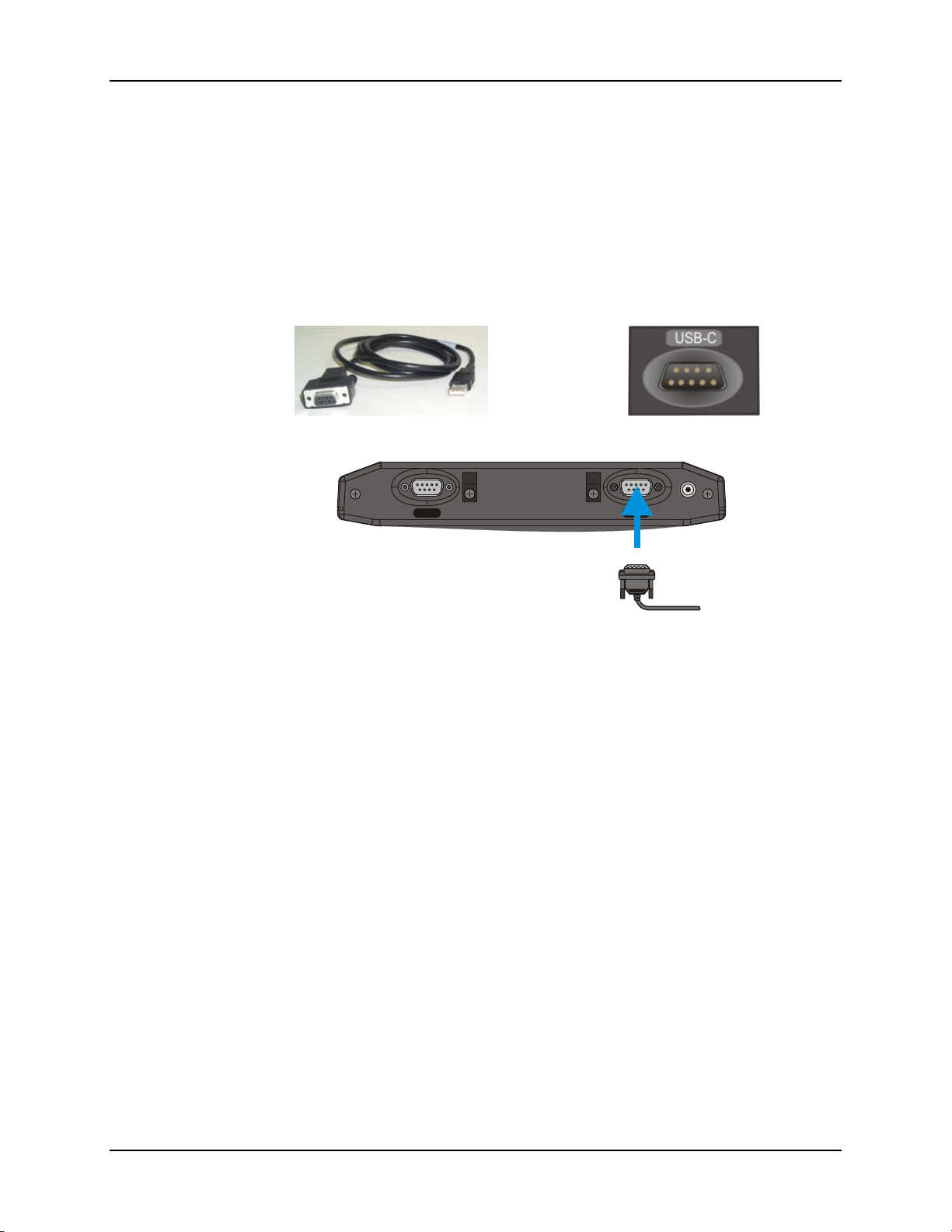
The USB-C connector accepts an adapter cable which provides a USB client port. Cable requires
a nine-pin D-shell female connector for the VX3Plus.
Port Label on Endcap
RS-232
USB-C
Figure 22 Connect USB-C Cable
1. Power off the VX3Plus before connecting the cable to the VX3Plus.
2. Seat the connector firmly over the pins and turn the thumbscrews in a clockwise
direction. Do not overtighten.
3. Use a strain relief clamp to secure the cable.
4. Press the power button to power up the VX3Plus.
5. Attach the USB end of the cable to the PC.
VX3Plus User’s Guide E-EQ-VX3PLUSOGWW-B
Page 43
USB-H Port 35
USB-H Port
Some endcap configurations contain a USB host port. This port is labeled USB-H. Please refer to
“Components” earlier in this manual for port identification.
Caution – Do Not Use the USB-H Labeled Port for scanners, PC serial cables or printers.
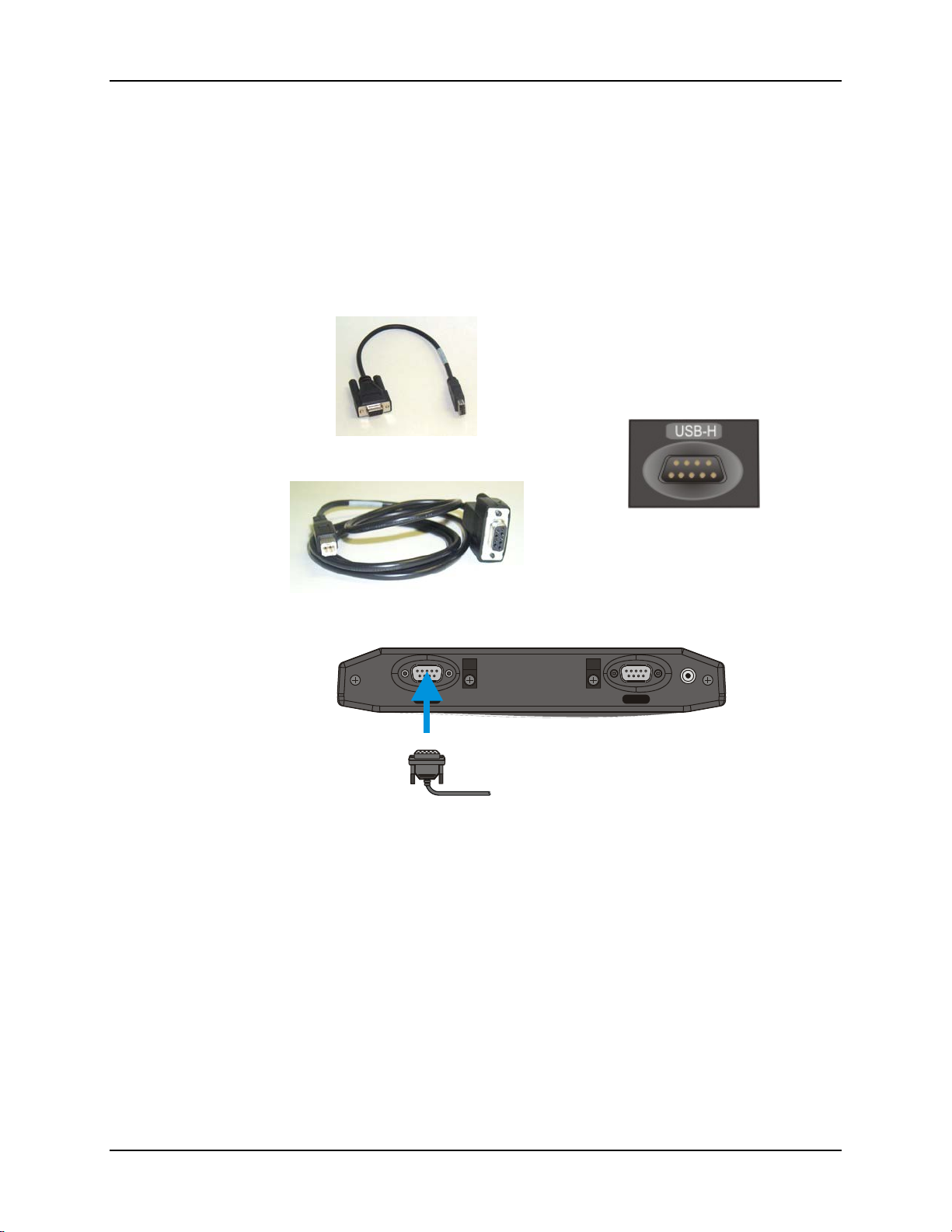
The USB-C connector accepts an adapter cable which provides a USB host port. Cable requires a
nine-pin D-shell female connector for the VX3Plus.
UBS Host Type A
Port Label on Endcap
USB Host Type B
RS-232
USB-C
Figure 23 Connect USB-H Cable
1. Power off the VX3Plus before connecting the cable to the VX3Plus.
2. Seat the connector firmly over the pins and turn the thumbscrews in a clockwise
direction. Do not overtighten.
3. Use a strain relief clamp to secure the cable.
4. Press the power button to power up the VX3Plus.
E-EQ-VX3PLUSOGWW-B VX3Plus User’s Guide
Page 44
36 Connect External Headset
Connect External Headset
Note: When the remote antenna mount is ordered, the VX3Plus does not have an audio
connector.
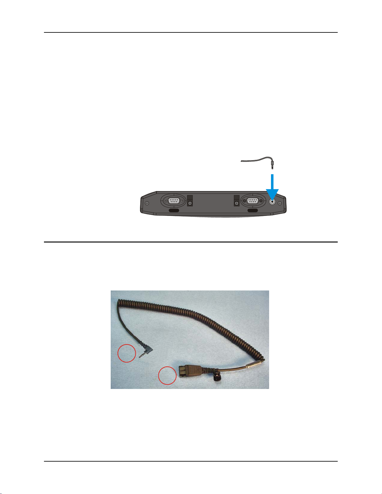
The VX3Plus provides an external headset connection via an audio jack connector labeled
“Audio”. The audio jack accepts a headset with a 2.5mm plug, such as a mono headset with
microphone or a stereo headset. Please refer to the VX3Plus Reference Guide for information on
configuring the audio port for a mono headset with microphone or a stereo headset.
An adapter cable (LXE Part No. 9000A076CBLHEADSET1) can be attached to the audio port.
The adapter cable has a 2.5mm plug on one end to attach to the VX3Plus and a quick disconnect
connector on the other end to connect to a variety of LXE voice recognition headsets.
T10A, 125V
LXE Headsets
A coiled headset adapter cable is used to connect the VX3Plus to an LXE headset.
RS-232
Figure 24 Connect External Headset
1. Insert the 2.5mm end of the adapter cable into the audio jack.
USB-C
2
1
1
Quick
Disconnect
Connector
2 2.5mm
Connector
Figure 25 Headset Adapter Cable Components
2. Use a strain relief clamp to secure the cable.
VX3Plus User’s Guide E-EQ-VX3PLUSOGWW-B
Page 45
Connect External Headset 37
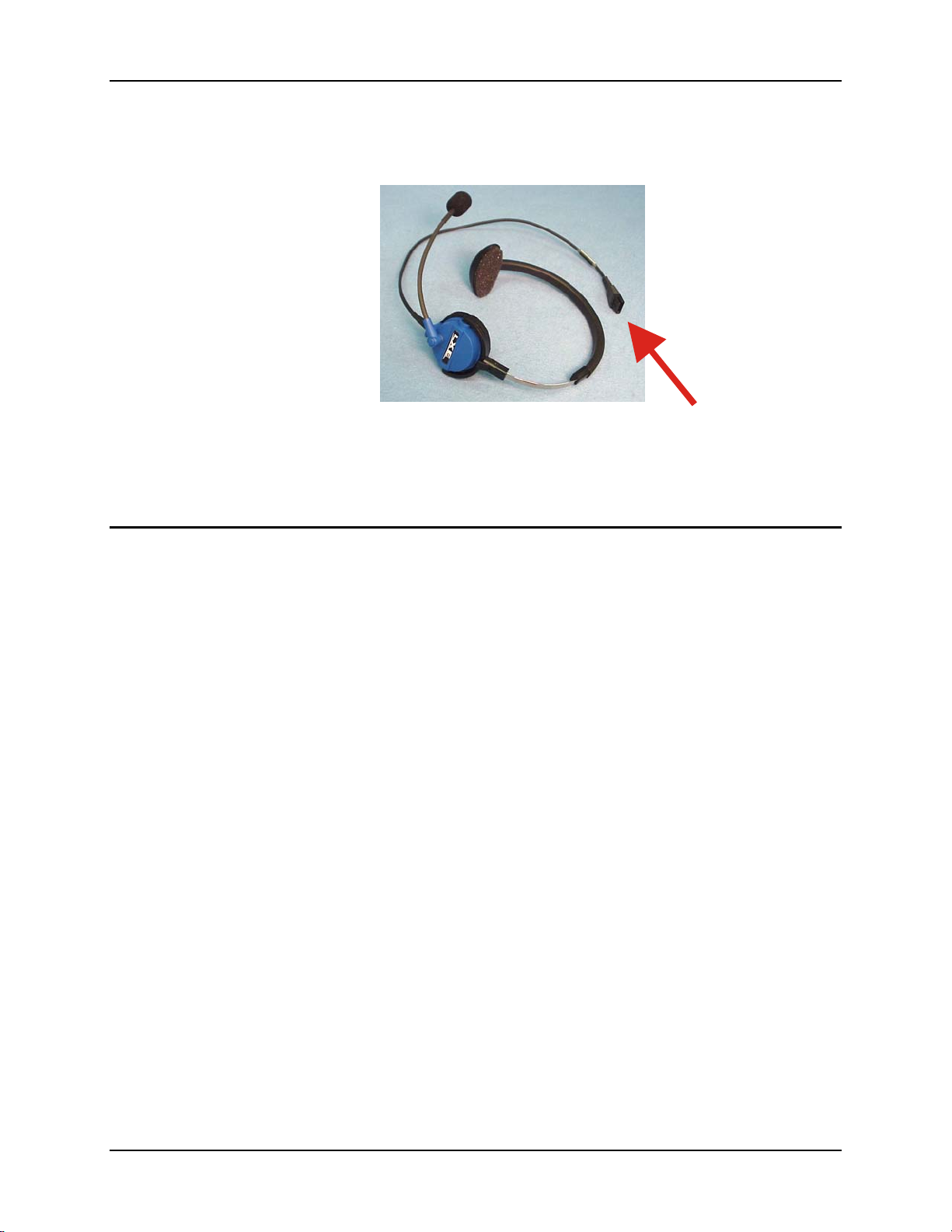
3. Connect the quick connect end of the adapter cable to the LXE headset. Align the
pins and push the connectors together until they click and are locked in place.
Figure 26 Headset Quick Disconnect Connector
4. If the adapter cable is removed from the VX3Plus, replace the plug to ensure the
VX3Plus is environmentally sealed.
Other Headsets
The audio jack accepts a headset with a 2.5mm plug, such as a mono headset with microphone or
a stereo headset.
1. Insert the speaker or headphone plug into the audio connector; making sure the plug is
firmly seated in the audio jack.
2. Replace the plug when the speaker or headset is removed from the audio jack.
3. Use a strain relief clamp to secure the cable.
E-EQ-VX3PLUSOGWW-B VX3Plus User’s Guide
Page 46
38 Connect Antenna
Connect Antenna
If the VX3Plus has the optional remote mount external antenna, please refer to the “Vehicle
Remote Mount Antenna Installation Sheet”, available on the LXE Manuals CD or ServicePass
website, for details.
If the VX3Plus has an internal antenna (no antenna connector on the endcap), the antenna was
connected when the VX3Plus was manufactured.
Connect Power Cable
1. Connect the power cable to vehicle power (See the following section titled “Vehicle
12-80VDC Direct Connection”.)
- or -
to an AC adapter. (See the following section titled “External Power Supply”.).
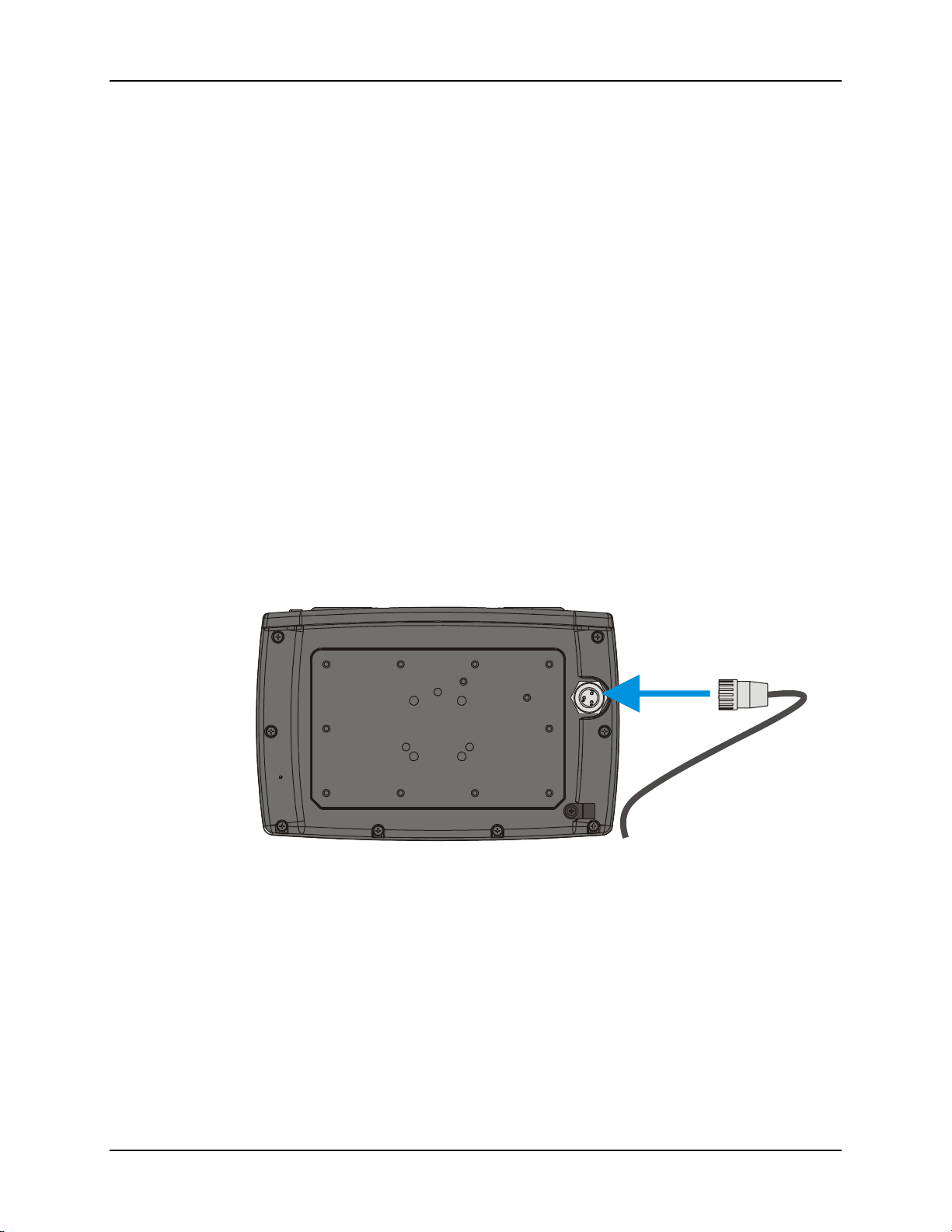
2. The plug and receptacle are keyed and care must be used when connecting the cables.
Tighten the nut of the plug clockwise until tight.
Secure the cable with the strain relief cable clamps.
Figure 27 Connect Power Cable to VX3Plus
3. Turn the VX3Plus on.
VX3Plus User’s Guide E-EQ-VX3PLUSOGWW-B
Page 47
External Power Supply, Optional 39
External Power Supply, Optional
The LXE-approved AC Power Supply and Adapter Cable are only intended for use in a 25ºC
(77ºF) maximum ambient temperature environment.
AC Power Supply
In North America, this unit is intended for use with a UL Listed ITE power supply with
output rated 12 – 80 VDC, minimum 15W. Outside North America, this unit is intended for
use with an IEC certified ITE power supply with output rated 12 – 80 VDC, minimum 15W.
The external power supply may be connected to either a 120V, 60Hz supply or, outside North
America, to a 230V, 50Hz supply, using the appropriate detachable cordset. In all cases, connect
to a properly grounded source of supply provided with maximum 15 Amp overcurrent protection
(10 Amp for 230V circuits).
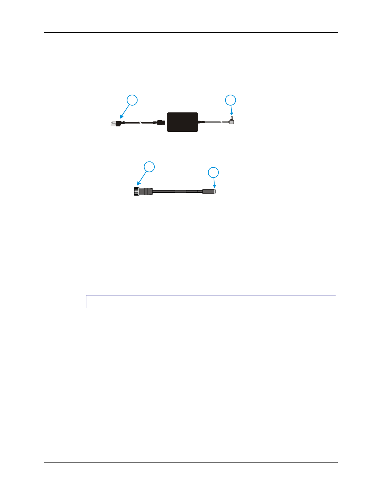
4
Adapter Cable, AC Power Supply to VX3Plus
Figure 28 Optional Power Configuration
21
3
1. AC Input Cable (US
only)
2. DC Output Cable
3. To DC Output Cable
(see above)
4. To VX3Plus
How To: Connect External Power Supply
1. Connect the detachable cordset provided by LXE (US only, all others must provide
their own cable) to the external power supply (IEC 320 connector).
2. Plug cordset into appropriate, grounded, electrical supply receptacle (AC mains).
3. Connect the DC Output Cable end to the corresponding connector on the Adapter
Cable.
3. Connect the watertight connector end of the Adapter Cable to the VX3Plus’s Power
Connector by aligning the connector pins to the power connector; push down on the
watertight connector and twist it to fasten securely.
4. Turn the VX3Plus on.
E-EQ-VX3PLUSOGWW-B VX3Plus User’s Guide
Page 48
40 Vehicle 12-80VDC Power Connection
Vehicle 12-80VDC Power Connection
Caution:
Caution:
Warning:
For proper and safe installation, the input power cable must be connected to a
!
fused circuit on the vehicle. This fused circuit requires a 2 Amp maximum time
delay (slow blow) high interrupting rating fuse. If the supply connection is
made directly to the battery, the fuse should be installed in the positive lead
within 5 inches of the battery positive (+) terminal.
For installation by trained service personnel only.
!
Risk of ignition or explosion. Explosive gas mixture may be vented from
!
battery. Work only in well ventilated area. Avoid creating arcs and sparks at
battery terminals.
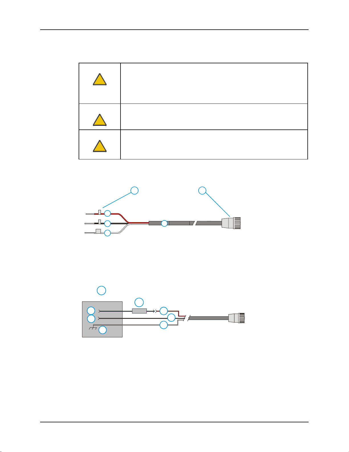
1. To Vehicle
1 2
Battery
2. To VX3Plus
+
3
-
4
GND
5
6
3. Red (DC+)
4. Black (DC-)
5. White (GND)
6. 12 – 80 VDC
Figure 29 Vehicle Power Connection Cable (Fuse Not Shown)
1. Vehicle Electrical
System
1
2
3
4
5
6
7
8
2. 2 Amp Slow
Blow Fuse
3. DC +
4. DC -
5. Vehicle Chassis
6. Red
7. Black
8. White
Figure 30 Connecting the Power Cable to the Vehicle
Note: Correct electrical polarity is required for safe and proper installation. See the following
figure titled “Vehicle Connection Wiring Color Codes” for additional wire color-coding
specifics.
VX3Plus User’s Guide E-EQ-VX3PLUSOGWW-B
Page 49

Vehicle 12-80VDC Power Connection 41
How To: Connect Vehicle 12-80VDC Connection
1. The VX3Plus must be turned off and the power cable must be UNPLUGGED from the
VX3Plus.
2. While observing the fuse requirements specified above, connect the power cable as
close as possible to the actual battery terminals of the vehicle. When available, always
connect to unswitched terminals in vehicle fuse panel, after providing proper fusing.
ATTENTION: For uninterrupted power, electrical supply connections should not
be made at any point after the ignition switch of the vehicle.
3. Route the power cable the shortest way possible. The cable is rated for a maximum
temperature of 75°C (167°F). When routing this cable it should be protected from
physical damage and from surfaces that might exceed this temperature.
Do not expose the cable to chemicals or oil that may cause the wiring insulation to
deteriorate.
Note: If the vehicle is equipped with a panel containing Silicon Controller Rectifiers
(SCR’s), avoid routing the power cable in close proximity to these devices.
Always route the cable so that it does not interfere with safe operation and maintenance
of the vehicle.
Use proper electrical and mechanical fastening means for terminating the cable.
Properly sized “crimp” type electrical terminals are an accepted method of termination.
Please select electrical connectors sized for use with 22AWG (1mm
2
) conductors.
Wiring color codes for LXE supplied DC input power cabling:
Vehicle Supply Wire Color
+12 - 80VDC (DC +) Red
Return (DC -) Black
Vehicle Chassis GND White
Figure 31 Vehicle Connection Wiring Color Codes
4. Provide mechanical support for the cable by securing it to the vehicle structure at
approximately one foot intervals, taking care not to over tighten and pinch conductors
or penetrate outer cable jacket.
5. Connect the power cable to the VX3Plus.
E-EQ-VX3PLUSOGWW-B VX3Plus User’s Guide
Page 50

42 Vehicle 12-80VDC Power Connection
VX3Plus User’s Guide E-EQ-VX3PLUSOGWW-B
Page 51
Power Button
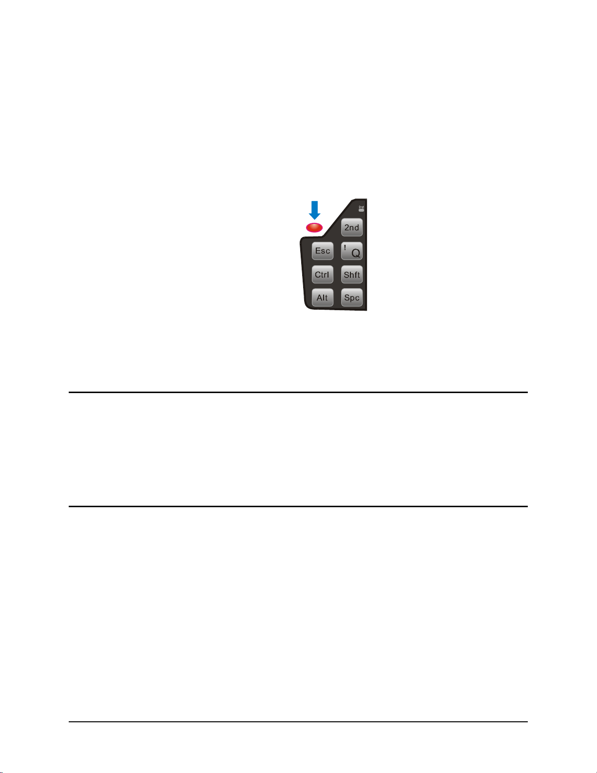
The power button is located above the ESC key on the keypad. After power is connected, the
Power button must be pressed to turn the device on.
Operation
Quickly tapping the Power button places the device immediately in Suspend mode. Quickly
tapping the Power button again, or touching the screen, immediately returns the device from
Suspend.
Power Management
Because the VX3Plus is powered by the vehicle battery, power management options are limited.
The display backlight can be configured to turn off after a specified period of inactivity. Please
see the “VX3Plus Reference Guide” for configuration details.
The VX3Plus can be placed in Suspend Mode. To enter suspend mode, tap the power button and
release or select Start | Suspend. To exit suspend tap the screen, press any key or tap the power
button.
Restart Sequence
Tap Start | Run, then type warmboot in the textbox and press Enter. If the touchscreen is not
accepting taps or needs recalibration, press <Ctrl>+<Esc> to force the Start Menu to appear.
When the Windows desktop is displayed or an application begins, the power on (or reboot)
sequence is complete. If any changes to the settings had been saved previously, they are restored
on reboot. There may be slight delays while the wireless client connects to the network, reauthorization for voice-enabled applications completes, Wavelink Avalanche management of the
VX3Plus startup completes, or Bluetooth relationships establish or re-establish.
Figure 32 Location of the Power (PWR) Button
E-EQ-VX3PLUSOGWW-B VX3Plus User’s Guide
Page 52

44 Display and Touchscreen
Display and Touchscreen
The VX3Plus Display is an LCD display capable of supporting Half VGA graphics modes.
Display size is half screen, 640 x 240 pixels. The display covering is designed to resist stains. The
touch screen allows signature capture and touch input. The display is either:
• An active transmissive display optimized for indoor viewing, or
• An active transflecive display optimized for outdoor viewing. A VX3Plus with this
display includes a “sun” logo to the bottom left of the keypad.
Display contrast adjustment is not necessary and the contrast adjustment key has no effect on the
VX3Plus.
The touch screen is a Resistive Panel with a scratch resistant finish that can detect touches by a
stylus, and translate them into computer commands. In effect, it simulates a computer mouse.
Only Delrin or plastic styluses should be used.
Note: Always use the point of the stylus for tapping or making strokes on the display. Never use
an actual pen, pencil or sharp object to write on the touch screen.
An extra or replacement stylus may be ordered from LXE. See the “Accessories” section for the
stylus part number.
Set the Display Backlight Timer
The Display Backlight Timer can be configured, if desired. For more information, please refer to
“Set the Display Backlight Timer” in the “VX3Plus Reference Guide”.
Set the Display Brightness
The brightness on the color display is incremented or decremented one step each time the arrow
key is pressed until either the maximum or minimum brightness is achieved (8 steps). The
brightness setting is recalled at power up.
• 2nd key then the <F10> key
• Use the Up Arrow and Down Arrow keys to adjust brightness until the display
lightens or darkens to your satisfaction.
• Press the Enter key to exit this mode.
nd
The LED for the 2
key blinks until the special editing mode (set display brightness) is complete.
VX3Plus User’s Guide E-EQ-VX3PLUSOGWW-B
Page 53

Display and Touchscreen 45
Cleaning the Display
Keep fingers and rough or sharp objects away from the display. If the glass becomes soiled or
smudged, clean only with a standard household cleaner such as Windex
Isopropyl Alcohol. Do not use paper towels or harsh-chemical-based cleaning fluids since they
may result in damage to the glass surface. Use a clean, damp, lint-free cloth. Do not scrub optical
surfaces. If possible, clean only those areas which are soiled. Lint/particulates can be removed
with clean, filtered canned air.
Disabling the Touchscreen
The touchscreen can be disabled, if desired. For more information, please refer to “Disabling the
Touchscreen” in the “VX3Plus Reference Guide”.
Calibrating the Touchscreen
Although the touch screen is installed and calibrated at the factory, users may make adjustments to
it. To calibrate the touchscreen, select Start | Settings and double tap the Stylus icon.
®
without vinegar or use
Figure 33 Touchscreen Calibration, Calibration Targets
The calibration utility displays a cross on the screen. Touch the center of the cross with the stylus
and hold for a few seconds. Release and repeat with the next cross. After all locations have been
touched, either press <Enter> or click the Calibration button.
Touchscreen Protective Film
LXE offers a replaceable touchscreen protective film to protect the touchscreen when the
VX3Plus is used in an abrasive environment. Installation and removal instructions can be found
earlier in this guide.
E-EQ-VX3PLUSOGWW-B VX3Plus User’s Guide
Page 54

46 Adjust Speaker Volume
Adjust Speaker Volume
The speaker is located on the front of the device above the Power button. The audio volume can
be adjusted to a comfortable level for the user. The volume is increased or decreased one step
each time the volume key is pressed. The device has an internal speaker and a jack for an external
headset. Operational “beeps” are emitted from the speaker.
Using the Keypad
Note: Volume & Sounds (in Control Panel) must be enabled before the following key sequences
will adjust the volume.
To adjust speaker volume, locate the <F8> key at the top of the keypad. Adjust the
speaker volume by pressing the:
nd
key then the <F8> key to enter Volume change mode.
2
Use the Up Arrow and Down Arrow keys to adjust volume until the speaker volume is
satisfactory.
Press the Enter key to exit this mode.
The LED for the 2
complete.
nd
key blinks until the special editing mode (set audio speaker volume) is
Using the Touchscreen
Select Start | Settings | Control Panel | Volume & Sounds | Volume tab. Change the volume
setting and tap OK to save the change. You can also select / deselect sounds for key clicks and
screen taps and whether each is loud or soft.
As the volume scrollbar is moved between Loud and Soft, the computer will emit a tone each time
the volume increases or decreases in decibel range.
Microsoft Windows CE Event Sounds
The VX3Plus includes a customized sound scheme. The customized WAV files are preferable to
the standard Microsoft Windows CE sounds when using the internal speaker.
VX3Plus User’s Guide E-EQ-VX3PLUSOGWW-B
Page 55
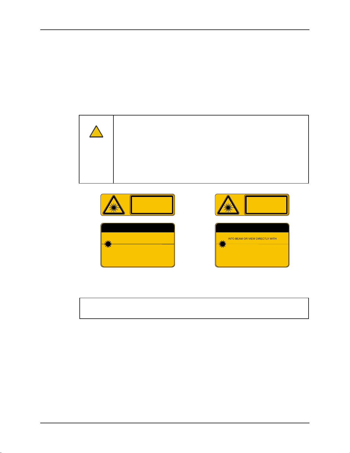
Laser Barcode Scanner Warnings 47
Laser Barcode Scanner Warnings
• Do not look into the laser’s lens.
• Do not stare directly into the laser beam.
• Do not remove the laser caution labels from the scanner.
• Do not connect the laser barcode module to any other device.
Caution:
!
Please read the caution labels.
Avoid exposure. Laser light is emitted from the scanner’s aperture.
Use of controls, adjustments or performance of procedures other than those
specified herein may result in hazardous radiation exposure.
The scanner uses laser light. The following labels are representations of caution
and warning labels placed on laser scanners.
IEC 825-1
1993
1ST ED.
LASER LIGHT - DO NOT
STARE INTO BEAM
CLASS 2 LASER PRODUCT
1.0 mW - 675nm
CAUTION
DO NOT STARE INTO BEAM
630-680nm LASER
1.0 MILLIWATT MAX OUTPUT
CLASS II LASER PRODUCT
COMPLIES WITH 21 CFR 1040.10 1040.11 AND IEC825
Figure 34 Caution Labels
Class II Scanner
IEC 825-1
1993
1ST ED.
LASER RADIATION
DO NOT STARE INTO BEAM OR
VIEW DIRECTLY WITH OPTICAL
INSTRUMENTS
CLASS 3A LASER PRODUCT
2.5 mW - 675nm
CAUTION
LASER RADIATION. DO NOT STARE
OPTICAL INSTRUMENTS.
675nm LASER
2.5 MILLIWATT MAX OUTPUT
CLASS IIIA LASER PRODUCT
COMPLIES WITH 21 CFR 1040.10 1040.11 AND IEC825
Figure 35 Caution Labels
Class IIIA Scanner
Do not pour, spray, or spill any liquid on the scanner. The Barcode Scanner contains the
circuitry, scanning motor and laser. Handle with appropriate care.
Enter Data
You can enter data into the VX3Plus through several different methods:
• The tethered scanner connected to the COM1 serial port provides barcode data entry
• The serial port and SUB port are used to input/output data
• The keyboard provides manual entry
• The touchscreen also provides manual entry
E-EQ-VX3PLUSOGWW-B VX3Plus User’s Guide
Page 56

48 Enter Data
Keyboard Entry
Refer to Appendix A “Key Maps” for specific keypresses.
The keyboard is used to manually input data that is not collected otherwise. Almost any function
that a full sized computer keyboard can provide is duplicated on the VX3Plus keyboard but it may
take a few more keystrokes to accomplish a keyed task.
Almost every key has two or three different functions. The primary alpha or numeric character is
printed on the key.
nd
For example, when the <2
nd
the <2
> character i.e. <2nd> + F1 toggles the CAPS Lock function. The specific <2nd> character
> key is selected pressing the desired second-function key produces
is printed above the corresponding key.
Please refer to Appendix A “Key Maps” for instruction on the specific keypresses to access all
PC-compatible keyboard functions.
Touchscreen Entry
Note: This section is directed to the VX3Plus user. The assumption is that the unit has been
configured and the touch panel calibrated by the System Administrator prior to releasing
the VX3Plus for use.
Right Click
Note: Always use the point of the stylus for tapping or making strokes on the display. Never use
an actual pen, pencil or sharp object to write on the touch screen.
The touchscreen input performs the same function as the mouse that is used to point to and click
elements on a desk top computer. The stylus is used in the same manner as a mouse – single tap or
double tap to select menu options, drag the stylus across text to select, hold the stylus down to
activate slider bars, etcetera. Holding the stylus down for ½ second performs the right mouse
click function.
When using a stylus, hold the stylus as if it were a pen or pencil. Touch an element on the screen
with the tip of the stylus then remove the stylus from the screen. The touch screen responds to an
actuation force (touch) of up to 4 oz. of pressure.
The touch screen can be used in conjunction with the keyboard and an input/output device
connected to one of the VX3Plus’s serial ports.
• Touch the stylus to the field of the data entry form to receive the next data feed.
• The cursor begins to flash in the field.
• The unit is ready to accept data from either the keyboard or a device connected to a
serial port.
A right click can be simulated on the touch screen. To perform a right click, touch the touch
screen with the stylus and hold it in the same location for a short time.
VX3Plus User’s Guide E-EQ-VX3PLUSOGWW-B
Page 57
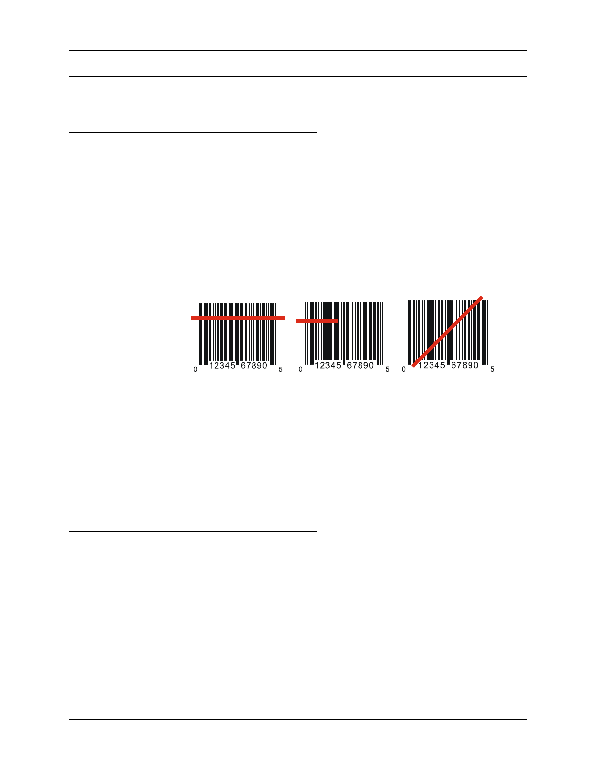
Enter Data 49
Tethered Scanner Entry
The following section is directed toward a generic tethered scanner connected to the COM1 serial
port on the VX3Plus.
Aiming the Barcode Scanner
Aim the scanner away from you, direct it at the barcode and press the trigger to scan.
The Scan On LED (or equivalent) turns red to indicate the scanner is on.
Adjust the aim so that the thin, red laser beam covers the entire length of the barcode.
Some scanners use a laser aiming beam which then spreads into a wide beam when the scanner’s
Aiming Beam Timer expires. Place the aiming beam in the center of the barcode and hold the
scanner steady until the beam spreads and the barcode is decoded. Beeps may be heard as the
barcode is decoded. Refer to the barcode scanner user’s guide for information on the Aiming
Beam Timer and beep sequences, and the TE reference guide for host generated beep sequences.
The scan beam must cross every bar and space on the barcode.
Distance from Label
Large barcodes can be scanned at the maximum distance. Hold the scanner closer to small
barcodes (or with bars that are very close together).
Note: Do not position the scanner exactly perpendicular to the barcode being scanned. In this
Successful Scan
When the scan is successful, the scanner’s good scan indicator illuminates, the scan on indicator is
off, and the currently running application may produce a distinctive audible tone.
Unsuccessful Scan
When the scan is unsuccessful, the scan on indicator remains illuminated and the currently
running application may produce distinctive audible tones. Check the following:
Correct Scan Incorrect Scan Incorrect Scan
Figure 36 Scan Beam
position, light can bounce back into the scanner’s exit window, and possibly prevent a
successful decode.
• Is the scanner programmed for the barcode being read?
• Check the barcode for marks or physical damage e.g. ripped label, missing section,
etc.
• Try scanning test symbols of the same code type at different distances and angles.
E-EQ-VX3PLUSOGWW-B VX3Plus User’s Guide
Page 58

50 Enter Data
Bluetooth Scanners
Bluetooth scanners are paired to the VX3Plus wirelessly using the VX3Plus Bluetooth wireless
client.
See previous sections on Bluetooth for more information.
Only LXE Bluetooth scanners and LXE Bluetooth printers are supported by LXE. See
Accessories.
Voice Data
Data is entered into the VX3Plus by speaking into the headset’s microphone when prompted.
Please contact your System Administrator if assistance is needed with the voice software.
VX3Plus User’s Guide E-EQ-VX3PLUSOGWW-B
Page 59
Bluetooth Devices 51
Bluetooth Devices
Assumption: The System Administrator has Discovered and Paired targeted Bluetooth devices
for each VX3Plus. The System Administrator has also enabled / disabled
Bluetooth settings and assigned a Computer Friendly Name for each VX3Plus.
See the VX3Plus Reference Guide for information and instruction on the VX3Plus,
Bluetooth control panel applet and supported LXE Bluetooth printers and
scanners.
The Bluetooth taskbar Icon state and Bluetooth scanner LED states change as Bluetooth devices
are discovered, pair, connect and disconnect. There may be audible or visual signals as paired
devices re-connect with the VX3Plus. Only LXE printers or scanners are recognized and
displayed in the Bluetooth panel. All other Bluetooth devices are ignored. (see VX3Plus
Reference Guide for details).
Taskbar
Icon
Note: When an active paired device, not the VX3Plus, enters Suspend Mode, is turned Off or
leaves the VX3Plus Bluetooth scan range, the Bluetooth connection between the linked
device and the VX3Plus is lost. There may be audible or visual signals as paired devices
disconnect from the VX3Plus.
Notes
• The VX3Plus does not have a Bluetooth managed LED.
• The LED on the Bluetooth scanner illuminates during a scanning operation; there is no
Scan LED on the VX3Plus.
• Barcode data captured by the Bluetooth scanner is manipulated by the settings in the
VX3Plus Scanner Properties control panel applet.
• Multiple beeps may be heard during a barcode scan using the Bluetooth scanner; beeps
from the Bluetooth scanner as the barcode data is accepted/rejected, and other beeps from
the VX3Plus during final barcode data manipulation.
Legend
Bluetooth module is connected to one or more of the targeted Bluetooth
device(s).
VX3Plus is not connected to any Bluetooth device.
VX3Plus is ready to connect with any Bluetooth device.
VX3Plus is out of range of all paired Bluetooth device(s). Connection is
inactive.
See Accessories for supported Bluetooth printers and scanners.
AppLock, if installed, does not stop the end-user from using Bluetooth, nor does it stop authorized
Bluetooth devices from pairing with the VX3Plus while AppLock is in control.
E-EQ-VX3PLUSOGWW-B VX3Plus User’s Guide
Page 60

52 Bluetooth Devices
VX3Plus User’s Guide E-EQ-VX3PLUSOGWW-B
Page 61
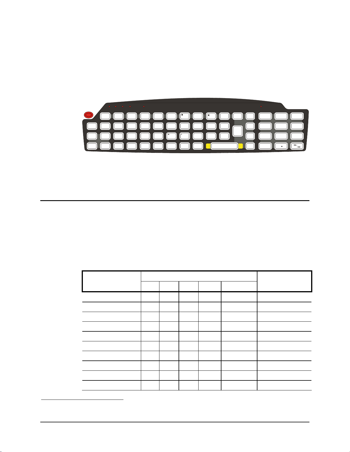
The VX3Plus Keypad
Appendix A Key Maps
ALT
CTRL SHFT CAPS STAT
2nd
CAPS
Break
F1 F2
$
#
@
WERTY
|\
ASDFGH
:; ,
ZXCVBNM
Esc
Ctrl
Alt
2nd
!
Shft
Spc
Q
The key map table that follows lists the commands used for the VX3Plus. Note that since the
VX3Plus uses a Microsoft Windows CE operating system, no DOS Terminal Emulation keypress
sequences are provided.
Key Map 101-Key Equivalencies
Note: This key mapping is used on VX3Plus computers that are NOT running LXE’s RFTerm.
When using a sequence of keys that includes the 2
key sequence.
Note: When the computer boots, the default condition of Caps (or CapsLock) is Off. The Caps
(or CapsLock) condition can be toggled with a 2
illuminated when CapsLock is On.
To get this key
?
Enter
BkLt
Ins
BkSp
F3
%
F5 F6
F4
^
&
U
~
`
F8 F9 F10
F7
*
()
IO P
.
J
KL
_
Figure 37 VX3Plus QWERTY Keyboard
nd
key, press the 2nd key first then the rest of the
nd
+F1 key sequence. The CAPS LED is
Press These Keys and Then
nd
2
Shift Ctrl Alt CapsLock
PgUp
/
789
PgDn
=
4
Home
[]
1
End
<
0
Press this key
-
+
{}
5
6
>
3
2
Del
Contrast 1 x F6
Volume x F8
Backlight x F10
2nd 2
nd
Shift Shft
Alt Alt
Ctrl Ctrl
Esc Esc
Space Spc
Enter Enter
1
The Contrast key sequence has no effect on the VX3Plus since display contrast is not adjustable.
E-EQ-VX3PLUSOGWW-B VX3Plus User’s Guide
Page 62

54 The VX3Plus Keypad
To get this key
2
Scan 2 Scan
CapsLock (Toggle) x F1
Back Space BkSp
Tab Tab
BackTab x Tab
Break x F2
Pause x x F3
Up Arrow Up Arrow
Down Arrow Down Arrow
Right Arrow Right Arrow
Left Arrow Left Arrow
Insert x BkSp
Delete x DOT
Home x Left Arrow
End x Right Arrow
Press These Keys and Then
nd
Shift Ctrl Alt CapsLock
Press this key
Page Up x Up Arrow
Page Down x Down Arrow
ScrollLock x x F4
F1 F1
F2 F2
F3 F3
F4 F4
F5 F5
F6 F6
F7 F7
F8 F8
F9 F9
F10 F10
F11 x x F1
F12 x x F2
a Off A
b Off B
c Off C
2
Left Scan key default value is Scan, however this key has no affect on an external scanner
attached to the VX3X. Right Scan key default value is Enter.
VX3Plus User’s Guide E-EQ-VX3PLUSOGWW-B
Page 63

The VX3Plus Keypad 55
To get this key
2
d Off D
e Off E
f Off F
g Off G
h Off H
i Off I
j Off J
k Off K
l Off L
m Off M
n Off N
o Off O
p Off P
q Off Q
r Off R
Press These Keys and Then
nd
Shift Ctrl Alt CapsLock
Press this key
s Off S
t Off T
u Off U
v Off V
w Off W
x Off X
y Off Y
z Off Z
A x A
B x B
C x C
D x D
E x E
F x F
G x G
H x H
I x I
J x J
K x K
L x L
E-EQ-VX3PLUSOGWW-B VX3Plus User’s Guide
Page 64

56 The VX3Plus Keypad
To get this key
2
M x M
N x N
O x O
P x P
Q x Q
R x R
S x S
T x T
U x U
V x V
W x W
X x X
Y x Y
Z x Z
1 1
Press These Keys and Then
nd
Shift Ctrl Alt CapsLock
Press this key
2 2
3 3
4 4
5 5
6 6
7 7
8 8
9 9
0 0
DOT DOT
< x 0
[ x 1
] x 2
> x 3
= x 4
{ x 5
} x 6
/ x 7
- x 8
+ x 9
VX3Plus User’s Guide E-EQ-VX3PLUSOGWW-B
Page 65

The VX3Plus Keypad 57
To get this key
2
* x I
: (colon) x D
; (semicolon) x F
? x L
` x N
_ (underscore) x M
, (comma) x J
‘ (apostrophe) x H
~ (tilde) x B
\ x S
| x A
“ x G
! x Q
@ x W
# x E
Press These Keys and Then
nd
Shift Ctrl Alt CapsLock
Press this key
$ x R
% x T
^ x Y
& x U
( x O
) x P
E-EQ-VX3PLUSOGWW-B VX3Plus User’s Guide
Page 66
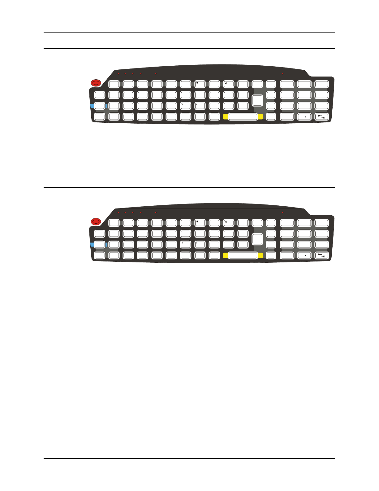
58 The VX3Plus Keypad
IBM 3270 Keypad Overlay
ALT
CTRL SHFT CAPS STAT
2nd
Esc
Ctrl
Alt
2nd
!
Shft
Spc
Q
PA1 PA2 PA3
CAPS
Break
F1 F2
#
@
WERTY
Attn
|\
ASDFGH
ZXCVBNM
F3
Rst
%
$
SysReq
Del
:; ,
Clr
F5 F6
F4
^
&
~
`
F7
*
U
NL
_
F8 F9 F10
Ins
()
IO P
.
J
?
KL
Enter
BkLt
Ins
BkSp
E - Inp
PgUp
/
789
PgDn
=
4
Home
[]
1
End
<
0
-
+
{}
5
6
>
3
2
Del
Figure 38 IBM 3270 Specific Keypad
The 60-key keypad is available with an IBM 3270 overlay designed to allow the user to enter
terminal emulator commands when running LXE’s RFTerm™ program. When running this
program please refer to the following reference guide for equivalent keys and keypress sequences:
• RFTerm™ Reference Guide
IBM 5250 Keypad Overlay
ALT
CTRL SHFT CAPS STAT
2nd
BkLt
Ins
BkSp
E - Inp
PgUp
/
789
PgDn
=
4
Home
[]
1
End
<
0
-
+
{}
5
6
>
3
2
Del
Esc
Ctrl
Alt
2nd
!
Shft
Spc
Q
CAPS
Break
F1 F2
#
@
WERTY
Attn
|\
ASDFGH
ZXCVBNM
F3
%
$
SysReq
Del
:; ,
Clr
F5 F6
F4
^
&
~
`
F7
Dup
*
U
NL
_
F8 F9 F10
Ins
()
IO P
.
J
Fld -
Fld +
?
KL
Enter
Figure 39 IBM 5250 Specific Keypad
The 60-key keypad is available with an IBM 5250 overlay designed to allow the user to enter
terminal emulator commands when running LXE’s RFTerm™ program. When running this
program please refer to the following reference guide for equivalent keys and keypress sequences:
• RFTerm™ Reference Guide
VX3Plus User’s Guide E-EQ-VX3PLUSOGWW-B
Page 67

Appendix B Regulatory Notices and Safety Information
FCC Information:
This device complies with FCC Rules, part 15. Operation is subject to the following conditions:
1. This device may not cause harmful interference
and
2. This device must accept any interference that may be received, including interference that may cause
undesired operation.
Note: This equipment has been tested and found to comply with the limits for a Class A digital device, pursuant
to part 15 of the FCC rules. These limits are designed to provide reasonable protection against harmful
interference when the equipment is operated in a commercial environment. This equipment generates, uses, and
can radiate radio frequency energy and, if not installed and used in accordance with the instruction manual, may
cause harmful interference to radio communications. Operation of this equipment in a residential area is likely to
cause harmful interference in which case the user will be required to correct the interference at his own expense.
Warning: Changes or modifications to this device not expressly approved by LXE, Inc., could void the user’s
authority to operate this equipment.
EMC Directive Requirements:
This is a Class A product. In a domestic environment this product may cause radio interference in which case the
user may be required to take adequate measures.
Industry Canada:
This Class A digital apparatus meets all requirements of the Canadian Interference Causing Equipment
Regulations. Operation is subject to the following two conditions: (1) this device may not cause harmful
interference, and (2) this device must accept any interference received, including interference that may cause
undesired operation.
Cet appareil numérique de la classe A respecte toutes les exigences du Règlement sur le matériel brouilleur du
Canada. Le présent appareil numérique n’émet pas de bruits radioélectriques dépassant les limites applicables aux
appareils numériques de Classe A prescrites dans le Règlement sur le brouillage radioélectrique édits par le
ministère des Communications du Canada.
Notice:
The long term characteristics or the possible physiological effects of radio frequency electromagnetic fields have
not been investigated by UL.
RF Safety Notice:
Caution:
This device is intended to transmit RF energy. For protection against RF exposure to humans and in
accordance with FCC rules and Industry Canada rules, this transmitter should be installed such that
a minimum separation distance of at least 20 cm (7.8 in.) is maintained between the antenna and the
general population. This device is not to be co-located with other transmitters.
E-EQ-VX3PLUSOGWW-B VX3Plus User’s Guide
Page 68
60 Regulatory Notices
R&TTE Directive Requirements (Applies only to Equipment operated within the EU/EFTA)
Information to User
A label on the exterior of the device should resemble one of the labels shown below (the label contains
the LXE part number of the installed radio card). The labels shown below and affixed to the device,
identify where the device may be used and where its use is restricted. Use of a device is prohibited in
countries not listed below or otherwise identified by the label. (May or may not include the 0560 Notified
Body No.)
Approvals
Product EMI / EMC Standards Safety Standards
VX3Plus
Transceiver RF Standards Notes
4830 (LXE Model No.)
LXE 2.4GHz CF with Type II PCMCIA
Adapter Card
4831 (LXE Model No.)
LXE 5GHz CF with Type II PCMCIA
Adapter Card
FCC Part 15 Subpart B, Class A
EN 55022:1998
Class A
EN 55024:1998
Industry Canada Class A
FCC Part 15
FCC Bulletin OET-65
EN 300 328
IC-RSS 210
IC-RSS 102
FCC Part 15
FCC Bulletin OET-65
EN 300 328
EN 301 893
IC-RSS 210
IC-RSS 102
UL 60950-1:2003 For indoor use or use in
an enclosed vehicle only
CSA C22.2 No. 60950-1:2003
EN 60950-1:2001
IEC 60950-1:2001
Unlicensed Operation
Unlicensed Operation
Requires License for Outdoor Use
Unlicensed Operation
Unlicensed Operation
Requires License for Outdoor Use
Important: This symbol is placed on the product to remind users to dispose of Waste Electrical
and Electronic Equipment (WEEE) appropriately, per Directive 2002-96-EC. In most areas,
this product can be recycled, reclaimed and re-used when properly discarded. Do not discard
labeled units with trash. For information about proper disposal, contact LXE through your
local sales representative, or visit www.lxe.com.
VX3Plus User’s Guide E-EQ-VX3PLUSOGWW-B
Page 69

Regulatory Notices 61
!
Caution:
Lithium battery inside. Danger of explosion if battery is incorrectly replaced. Replace only with same or equivalent
type recommended by battery manufacturer. (US)
Attention:
Contient une pile de lithium. Risque d’explosion dans le cas où la pile ne serait pas correctement remplacée.
Remplacer uniquement avec une pile semblable ou equivalente au type de pile recommandé par le fabricant. (FR)
Forsigtig:
Indeholder lithiumbattterier. Risiko for eksplosion, hvis batteriet udskiftes forkert. Må kun udskiftes med samme
eller tilsvarende type, som anbefalet af fabikanten. (DK)
Varoitus:
Tämä tuote käyttää laservaloa. Skannerissa on jokin seuraavista tarroista. Lue Huomio-kohta. (FI)
Vorsicht:
Enthält Lithium-Batterie. Bei unsachgemäßem Ersatz besteht Explosionsgefahr. Nur durch gleichen oder vom
Hersteller empfohlenen Typ ersetzen. (DE)
Attenzione:
Batteria al litio. Pericolo di esplosione qualora la batteria venga sostituita in maniera scorretta. Sostituire solo con lo
stesso tipo o equivalente consigliato per il fabbricante. (IT)
Atenção:
Contém pilha de lítio. Há perigo de explosão no caso de uma substituição incorreta. Substitua somente pelo mesmo
tipo, ou equivalente, recomendado pelo fabricante. (PT)
Lithium Battery Safety Statement
!
Varning:
Innehåller litiumbatteri. Fara för explosion om batteriet är felaktigt placerat eller av fel typ. Använd endast samma
eller motsvarande typ batterier rekommenderade av tillverkaren. (SE)
Advarsel:
Innmontert Lithium batteri. Eksplosjonsfare ved feil montering av batteri. Benytt kun batteri anbefalt av produsent.
(NO)
Cuidado:
Pila de litio adentro. Peligro de explosión si la pila se reemplaza incorrectamente. Reemplace solamente con el
mismo tipo o equivalente recomendado por el fabricante. (ES)
Oppassen:
Bevat Lithium-batterij. Incorrrecte plaatsing van batterij kan leiden tot explosiegevaar. Alleen vervangen door
hetzelfde of door fabrikant aanbevolen gelijkwaardig type. (NL)
E-EQ-VX3PLUSOGWW-B VX3Plus User’s Guide
Page 70
62 Regulatory Notices
at:
!
(GR)
(JP)
Dikk
Lithium Battery Safety Statement
(KR)
(CN)
!
(TR)
Legend:
Chinese CN Italian IT
Danish DK Japanese JP
Dutch NL Korean KR
English US Norwegian NO
Finnish FI Portuguese PT
French FR Spanish ES
German DE Swedish SE
Greek GR Turkish TR
VX3Plus User’s Guide E-EQ-VX3PLUSOGWW-B
Page 71
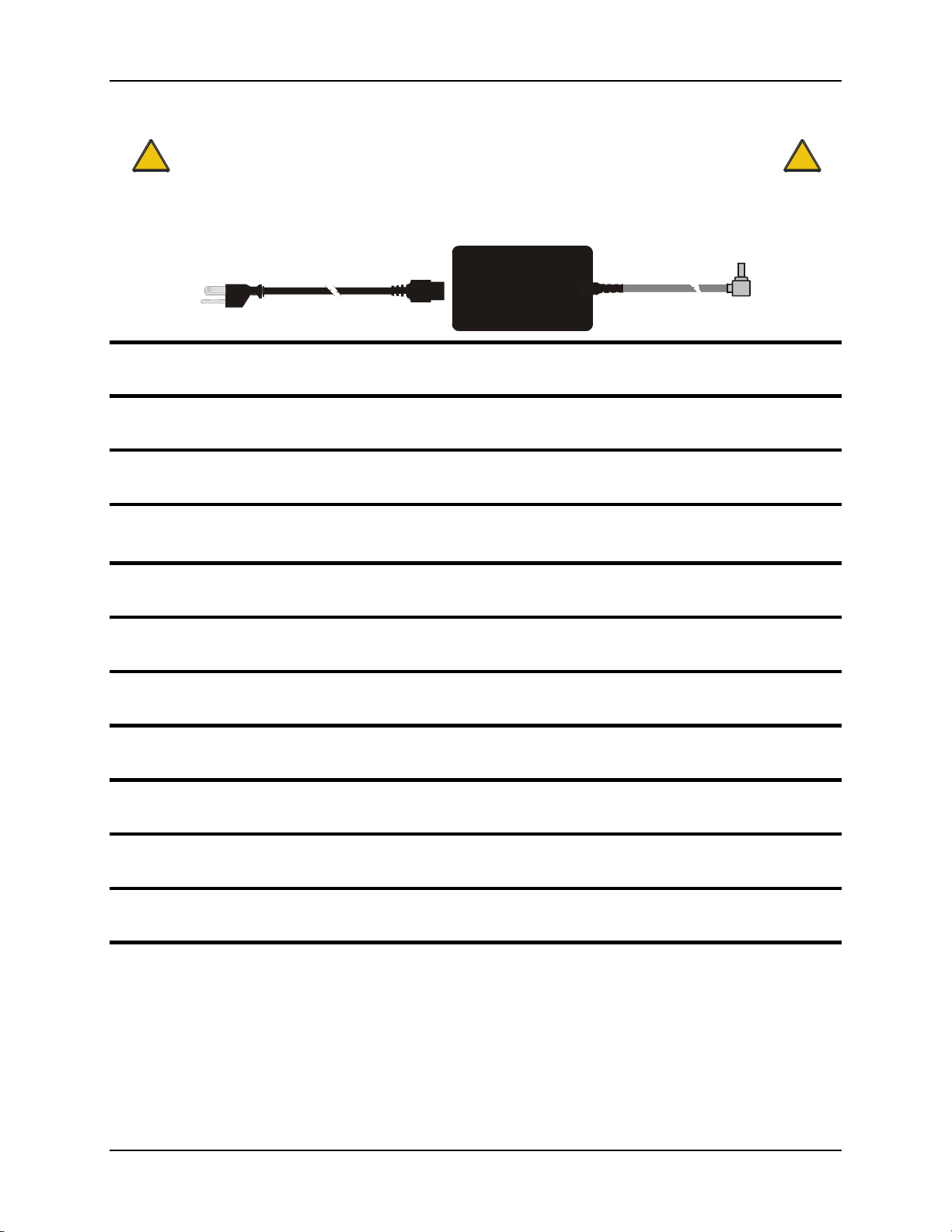
Regulatory Notices 63
A/C Power Supply Safety Statement – VX3Plus
!
Output Rated 12 – 80 VDC, Minimum 15W.
The LXE-approved AC Power Adapter is only intended for use in a 25ºC (77ºF) maximum
ambient temperature environment.
Optional A/C Power Supply:
Outside North America, this unit is intended for use with an IEC certified ITE power supply with output rated as stated
at the top of this page. (US)
Alimentation c.a. optionnelle:
Hors de l’Amérique du Nord, cette unité est conçue pour être utilisée avec une alimentation ITE certifiée CEI de sortie nominale
indiquée au haut de cette page. (FR)
Valgfrit vekselstrømforsygning
Udenfor Nord Amerika er denne enhed udstattet med en IEC (international elektronisk Kommission) udfærdiget med en ITE
strømforsygning med strømudgang som fastslået på denne sides begyndelse. (DK)
Vaihtoehtoinen vaihtovirran syöttölaite:
Pohjois-Amerikan ulkopuolella tämä laite on tarkoitettu käytettäväksi sellaisen IEC:n sertifioiman ITE-tehonsyöttölaitteen
kanssa, jonka antoteho on tämän sivun yläosassa esitetyn mukainen. (FI)
Optionales Netzteil (Wechselstrom)
Außerhalb Nordamerikas sollte diese Einheit über ein der IEC-Norm entsprechendes ITE-Netzteil gespeist werden, und zwar mit
einer wie oben auf dieser Seite genannten Ausspeisung. (DE)
Προαιρετική Τροφοδοσία Συνεχούς Ρεύματος
Εκτός Β. Αμερικής, η μονάδα αυτή προορίζεται για χρήση με ένα τροφοδοτικό ITE πιστοποιημένο κατά IEC με ονομαστική
ισχύ όπως δηλώνεται στην αρχή της σελίδας. (GR)
Alimentazione opzionale a corrente alternata:
Al di fuori dei paesi dell’America del nord, l’unità deve essere impiegata con un dispositivo d’alimentazione per attrezzature
informatiche approvato dalla IEC la cui potenza nominale sia pari a quella indicata all’inizio della pagina. (IT)
Vekselstrømforsyning (ekstrautstyr):
Utenfor Nord-Amerika skal dette produktet brukes med en IEC-sertifisert ITE-strømforsyning med klassifisert effekt som angitt
øverst på denne siden. (NO)
Fornecimento opcional de CA:
Fora dos EUA, esta unidade destina-se a ser usada com dispositivos de fornecimento de corrente ITE com certificação IEC, com
a capacidade indicada no topo desta página. (PT)
Suministro optativo de corriente alterna
Fuera de América del Norte, esta unidad se debe utilizar con un alimentador ITE homologado por la IEC (comisión
electrotécnica internacional) con una salida que tenga la calificación que figura en la parte superior de esta página. (ES)
Valfri A/C Strömförsörjning
Utanför Nordamerika är det meningen att denna enheten används med en IEC-certifierad ITE-strömförsörjare med den uteffekt
som anges längst uppe på den här sidan. (SE)
İsteğe Bağlı A/C Güç Kaynağı:
Kuzey Amerika dışında, bu ünite, çıkış sınıflandırması bu sayfanın başında belirtilen IEC sertifikalı bir ITE güç kaynağı ile
birlikte kullanılmak üzere tasarlanmıştır. (TR)
Updated 10/01/2001
Legend: Danish – DK; English – US; Finnish – FI; French- - FR; German – DE; Greek – GR; Italian – IT; Norwegian – NO;
Portuguese – PT; Spanish – ES; Swedish – SE; Turkish – TR.
!
E-EQ-VX3PLUSOGWW-B VX3Plus User’s Guide
Page 72

64 Regulatory Notices
!
Vehicle Power Supply Connection Safety Statement
!
Vehicle Power Supply Connection:
If the supply connection is made directly to the battery, a 2A slow-blow fuse should be installed in the positive lead
within 5 inches (12.7 cm.) of the battery positive (+) terminal. (US)
Raccordement de l’alimentation du véhicule
Si l’alimentation est raccordée directement à la batterie, un fusible à action retardée de 2A doit être installé sur le
câble positif à moins de 12,7 cm de la borne positive (+) de la batterie. (FR)
EL forsyning af køretøjet.
Er forsyningsforbindelsen direkte tilknyttet til batteriet og og tilsluttet til den positive part indenfor 12,7 cm (+
delen). vil der være en langsom tændelse af 2 ampere. (DK)
Kytkentä ajoneuvon virtalähteeseen
Jos virtaa otetaan suoraan akusta, 2 ampeerin hidas sulake on asennettava positiiviseen johtoon enintään 12 cm:n
etäisyydelle akun positiivisesta (+) navasta. (FI)
Anschluss an Fahrzeugbatterie
Bei direktem Anschluss an die Fahrzeugbatterie sollte eine träge 2A-Sicherung in die positive Leitung
zwischengeschaltet werden, und zwar nicht weiter als ca. 13 cm von der positiven (+) Batterieklemme entfernt.
(DE)
Σύνδεση Τροφοδοτικού Ισχύος Οχήματος
Αν η σύνδεση του τροφοδοτικού γίνει κατευθείαν στη μπαταρία, μια ασφάλεια βραδείας τήξης των 2A θα πρέπει να
τοποθετηθεί στο θετικό καλώδιο εντός 5 ιντσών (12,7 εκ.) του θετικού (+) ακροδέκτη της μπαταρίας. (GR)
Collegamento dell’alimentazione del veicolo
Se il collegamento dell’alimentazione viene stabilito direttamente con la batteria, è necessario installare un fusibile
ad azione lenta da 2 A nel conduttore positivo a meno di 5 in. (12,7 cm) dal terminale positivo (+) della batteria.
(IT)
Tilkople strømforsyningen til kjøretøyet
Hvis strømforsyningen koples direkte til batteriet, skal det installeres en 2 A treg sikring i den positive ledningen
innen 12,7 cm fra plusspolen (+) på batteriet. (NO)
Ligação do fornecimento de corrente do veículo
Se a ligação de fornecimento de corrente for ligada directamente à bateria, deve instalar-se um fusível de 2A no
terminal positivo, a 12,7 cm. do terminal positivo (+) da bateria. (PT)
Conexión de suministro eléctrico para el vehículo
Si el suministro eléctrico se proporciona directamente a la batería, se debe instalar un fusible de retardo de 2 A en el
conductor positivo, como máximo a 12,7 cm (5 pulgadas) del terminal positivo (+). (ES)
Fordonets strömförsörjningskoppling
Om strömkopplingen görs direkt till batteriet, måste en 2A-säkring installeras i den positivt laddade ledningen inom
12.7 cm från batteriets pluspol (+). (SE)
Taşıt Güç Kaynağı Bağlantısı
Kaynak bağlantısı doğrudan aküye yapılırsa, pozitif bağlantı kablosu üzerinde akünün pozitif (+) kutbuna 12.7 cm
mesafede 2A’lık yavaş atan bir sigorta monte edilmelidir. (TR)
Legend: Danish – DK; English – US; Finnish – FI; French- - FR; German – DE; Greek – GR; Italian – IT;
Norwegian – NO; Portuguese – PT; Spanish – ES; Swedish – SE; Turkish – TR.
Updated 02/10/2004
VX3Plus User’s Guide E-EQ-VX3PLUSOGWW-B
Page 73

Regulatory Notices 65
Revision History
Revision A, Initial Release: May 2008
Revision B: September 2008
Section Explanation
Appendix B Regulatory Notices
and Safety Information
Update approvals for 802.11 a/b/g radio.
Remove Summit Declaration of Compliance for consistency.
E-EQ-VX3PLUSOGWW-B VX3Plus User’s Guide
Page 74

66 Regulatory Notices
VX3Plus User’s Guide E-EQ-VX3PLUSOGWW-B
Page 75

Numeric
Index
Pixels...............................................................8, 44
Document Conventions .............................................3
2nd key function .......................................................12
A
Aim Barcode Scanner..............................................49
Alt key function.......................................................12
AppLock....................................................................9
Audio Volume settings ............................................46
B
Backup Battery ........................................................17
Barcode Scanner......................................................31
Barcode scanner data entry......................................48
Battery, Backup, Lithium ........................................17
Beam, Long Range Scanner ....................................49
Bluetooth printers and scanners...............................51
Bottom Mounting Bracket.......................................25
Bracket
How To ...............................................................25
Tools Required....................................................23
C
Caps mode function.................................................13
Cleaning
Display ................................................................45
Color Codes, Wiring................................................41
Connection
COM1 .................................................................31
COM3 .....................................................33, 34, 35
External Speakers................................................36
Control Panel, Windows CE......................................8
Controls, Physical....................................................43
CPU ...........................................................................1
Ctrl key function......................................................12
Custom Key Maps ...................................................13
E
End user switching
Touch ....................................................................9
Enter Data, How To.................................................47
Enter key function ...................................................12
Environmental Specifications....................................3
External Speakers ....................................................36
F
Features .....................................................................1
Flash Memory............................................................1
Function
nd
Key ................................................................12
2
Alt Key................................................................12
Caps Mode ..........................................................13
Ctrl Key...............................................................12
Enter Key ............................................................12
Shft Key ..............................................................12
Spc Key...............................................................12
G
Getting Started...........................................................4
Good Scan LED.......................................................32
H
Headphone Jack.......................................................36
How To
Aim the Scan Beam.............................................49
Connect 12-80VDC Vehicle Power....................41
Connect Barcode Scanner ...................................31
Connect External Speakers .................................36
Connect Serial Printer .............................33, 34, 35
Install Vehicle Mounting Brackets .....................23
Keyboard data entry............................................48
D
Data entry, How To .................................................47
Display.......................................................................8
Cleaning ..............................................................45
Features...............................................................44
E-EQ-VX3PLUSOGWW-B VX3Plus User’s Guide
I
Input Cable, Max Temp rating ................................41
Install
External Speakers..........................................36, 37
Page 76

68 Index
Mounting Brackets, Vehicle ...............................23
Optional Power Supply.......................................39
Printer or PC ...........................................33, 34, 35
Scanner................................................................31
K
Key Map ..................................................................53
TN3270 keypads .................................................58
Keyboard data entry ................................................48
keyboard shortcuts...................................................15
Keymaps..................................................................53
Keypad Shortcuts.....................................................13
L
Laser Aperture.........................................................32
Laser barcode scanner warnings..............................47
LEDs
nd
function..........................................................14
2
ALT function ......................................................14
CAPS function ....................................................14
CTRL function....................................................14
on keypads,location.............................................14
SHFT function ....................................................14
STAT function ....................................................14
M
Manuals ...................................................................18
Maximum overcurrent protection............................39
Measurement,Torque...............................................24
Mode Key Functions ...............................................13
N
Nine-pin D-shell female connector
and the Scanner...................................................31
for printer or PC......................................33, 34, 35
O
Operating Temperature..............................................3
Overcurrent protection.............................................39
P
Protective Film ........................................................30
Q
Quick Start Instructions.............................................4
S
Scanner
Nine-pin D-shell female connector.....................31
Scanner data entry ...................................................48
Scanner Installation .................................................31
Scanning distance ....................................................49
Serial Printer................................................33, 34, 35
Shielded Cable
and the PC or printer...............................33, 34, 35
Shielded Cable Requirement ...................................31
Shift key function ....................................................12
Silicon Controller Rectifiers (SCR's) ......................41
Sizing of electrical connectors for use with 22AWG
conductors ...........................................................41
Space key function ..................................................12
Speaker Volume ......................................................46
using keypad .......................................................46
using touchscreen................................................46
Specifications
Environmental.......................................................3
Stylus .................................................................44, 48
Stylus Clip ...............................................................30
Stylus Data Entry.....................................................48
Successful Scan indicators ......................................49
SVGA graphics modes ..............................................8
T
Terminal Emulator List .............................................1
Thin Film Transistor (TFT) Display..........................8
Tools Required
Phillips No. 1 Screwdriver..................................23
Torque Wrench ...................................................24
Torque Wrench........................................................23
Touch Screen.....................................................44, 48
Touch Screen and Keypad Shortcuts.......................13
Touchscreen
Data Entry ...........................................................48
Finger or Stylus...................................................48
Trigger .....................................................................32
Pen Stylus ..........................................................44, 48
Polarity ....................................................................41
Power Button...........................................................43
Printer ..........................................................33, 34, 35
Procedure
Mounting Brackets..............................................25
U
Unsuccessful Scan indicators ..................................49
VX3Plus User’s Guide E-EQ-VX3PLUSOGWW-B
Page 77

Index 69
V
Vehicle Mounting Bracket, Installation Procedure .23
Vehicle Power
12V to 80V DC ...................................................17
External Power Supply .......................................39
View
Display ................................................................44
Voice data................................................................50
Volume
adjust audio volume ............................................46
VX3Plus Reference Guide ........................................2
W
Warning
Laser light ...........................................................47
Windows CE
Control Panel ........................................................8
Help Screens .........................................................8
Windows CE online Help..........................................8
Wiring Color Codes.................................................41
E-EQ-VX3PLUSOGWW-B VX3Plus User’s Guide
Page 78

70 Index
VX3Plus User’s Guide E-EQ-VX3PLUSOGWW-B
 Loading...