

Page 1
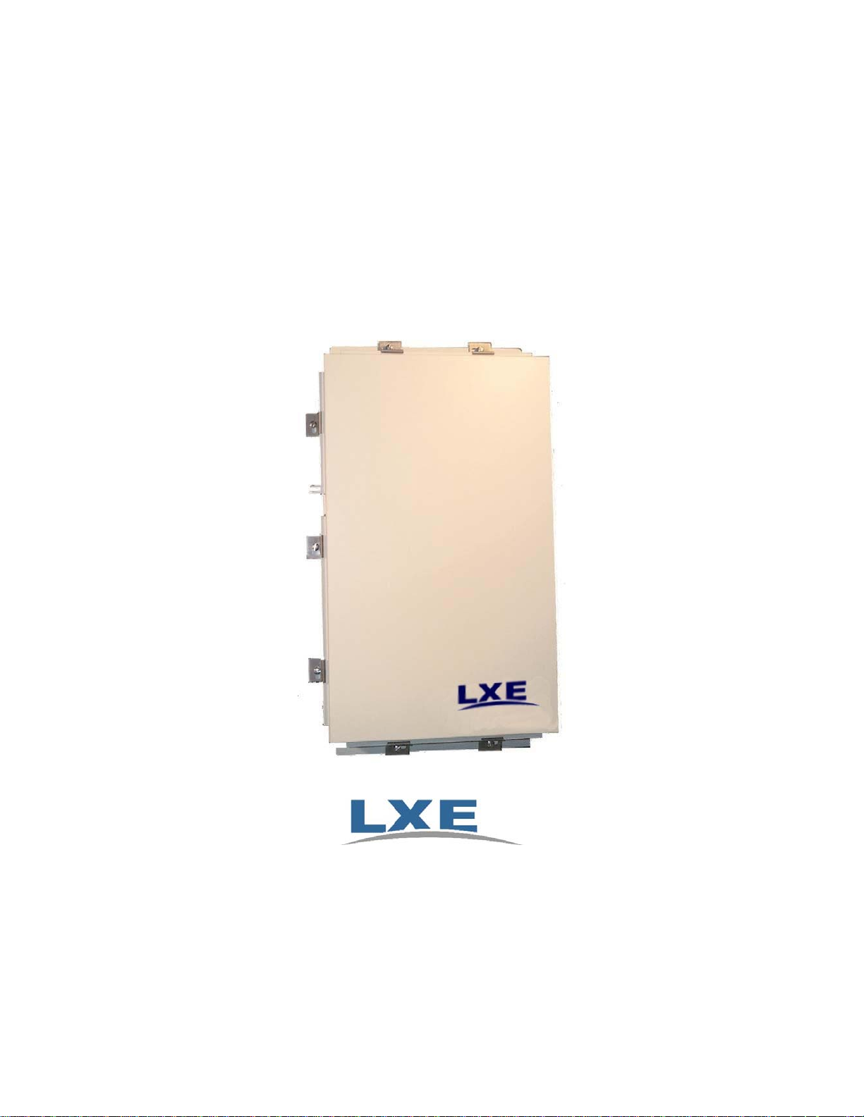
NEMA Type 4 Enclosure Reference
Guide
Copyright © December 2006 by LXE Inc.
All Rights Reserved
E-EQ-NEMARG-F
Page 2

Notices – Please Read
LXE Inc. reserves the right to make improvements or changes in the products described in this manual at any time
without notice. While reasonable efforts have been made in the preparation of this document to assure its accuracy,
LXE assumes no liability resulting from any errors or omissions in this document, or from the use of the information
contained herein. Further, LXE Incorporated, reserves the right to revise this publication and to make changes to it
from time to time without any obligation to notify any person or organization of such revision or changes.
Copyright:
This manual is copyrighted. All rights are reserved. This document may not, in whole or in part, be copied,
photocopied, reproduced, translated or reduced to any electronic medium or machine-readable form without prior
consent, in writing, from LXE Inc.
Copyright © 2006 by LXE Inc. An EMS Technologies Company. 125 Technology Parkway, Norcross, GA 30092
U.S.A. (770) 447-4224
Trademarks:
LXE® is a registered trademark of LXE Inc.
All other brand or product names are trademarks or registered trademarks of their respective companies or
organizations.
When this manual is in PDF format: “Acrobat ® Reader Copyright © 1987-2006 Adobe Systems Incorporated. All
rights reserved. Adobe, the Adobe logo, Acrobat, and the Acrobat logo are trademarks of Adobe Systems
Incorporated.” applies.
Important Notice:
Please refer to the documentation for enclosed access points and or bridges for additional regulatory and safety
information, including, but not limited to:
• RF Safety Notices
• FCC Information
• EMC Directive Requirements
• Industry Canada Notices
Approvals
NEMA Enclosure Regulatory Information:
Compliance Category Applicable Standards Corresponding Markets
Safety
Notes: European Union countries = Austria, Belgium, Denmark, Finland, France, Germany, Greece,
Ireland, Italy, Luxembourg, Netherla n ds, P ortugal, Spain, Sweden and United Kingdom.
EN60950 = IEC 950 with European national deviations
UL 50
NEMA Type 4
IEC60529
EN60950
U.S., Canada + Argentine, Brazil, Chile, Costa Rica,
Hong Kong, Mexico, New Zealand, Peru, Philippines,
Singapore
EU + Switzerland and Norway
Page 3

Revision Notice
NEMA Type 4 Enclosure Reference Guide
Upgrade From Revision E to Revision F
Section Explanation
Chapter 1 – Introduction Updated accessories listing.
Appendix B – I nstallation
Procedure Sheets
Appendix C – Installation Procedure
Sheets (RoHS)
Note: A complete revision history is included in Appendix A, “Technical Specifications”.
Renamed to Appendix B, “Installation Procedure Sheets (nonRoHS).
Revised section: “Introduction”.
Added new appendix.
E-EQ-NEMARG-F NEMA Type 4 Enclosure Reference Guide
Page 4

Page 5

Table of Contents
CHAPTER 1 INTRODUCTION 1
Features.....................................................................................................................1
External Interfaces....................................................................................................................1
Electrical.................................................................................................................................1
Ethernet ..................................................................................................................................1
Antenna ..................................................................................................................................
Security.....................................................................................................................................
Mounting...................................................................................................................................3
Enclosed Devices......................................................................................................................3
Heater........................................................................................................................................4
Lightning Suppression..............................................................................................................4
Components..............................................................................................................5
Configuration .......................................................................................................... 10
2
3
When to Use This Guide......................................................................................... 10
Document Conventions ..........................................................................................................10
Getting Help.............................................................................................................11
Accessories............................................................................................................. 11
CHAPTER 2 INSTALLATION 13
Step 1: Assemble Internal Components ............................................................... 13
Step 2: Mount NEMA Enclosure ............................................................................ 15
Direct Wall Mount..................................................................................................................15
Using a Mounting Board ........................................................................................................15
Step 3: Route AC Power and Ethernet.................................................................
Important Notes......................................................................................................................18
Step 4: Complete Installation................................................................................
Fuse Replacement ..................................................................................................
Completed Installation............................................................................................20
APPENDIX A TECHNICAL SPECIFICATIONS 21
16
19
19
Physical Specifications.......................................................................................... 21
Environmental Specifications................................................................................
Enclosed Devices ...................................................................................................
E-EQ-NEMARG-F NEMA Type 4 Enclosure Reference Guide
21
22
Page 6

ii Table of Contents
Revision History...................................................................................................... 23
APPENDIX B INSTALLATION PROCEDURE SHEETS (NON-ROHS) 25
Introduction............................................................................................................. 25
Installation Procedure, LXE Model 6520 AP (non-RoHS) .................................... 27
Installation Procedure, LXE Model 6540 AP (non-RoHS) .................................... 35
Installation Procedure, LXE Model 6543 Bridge (non-RoHS).............................. 43
Installation Procedure, LXE Models 6453 Bridge & 6540 AP (non-RoHS).......... 51
Installation Procedure, LXE Model 6720 AP (non-RoHS) .................................... 61
Installation Procedure, LXE Model 6730 AP (non-RoHS) .................................... 69
Installation Procedure, LXE Models 6723 Bridge & 6730 AP (non-RoHS).......... 83
Installation Procedure, LXE Models 6723 Bridge & 6720 AP (non-RoHS).......... 99
Installation Procedure, Lightning Suppression Accessories (non-RoHS)....... 111
APPENDIX C INSTALLATION PROCEDURE SHEETS (ROHS) 117
Introduction........................................................................................................... 117
Installation Procedure, LXE Model 6520 AP (RoHS).......................................... 119
Installation Procedure, LXE Model 6540 AP (RoHS).......................................... 127
Installation Procedure, LXE Model 6543 Bridge (RoHS).................................... 135
Installation Procedure, LXE Models 6453 Bridge & 6540 AP (RoHS) ............... 143
Installation Procedure, LXE Model 6720 AP (RoHS).......................................... 153
Installation Procedure, LXE Model 6730 AP (RoHS)..........................................
Installation Procedure, LXE Models 6723 Bridge & 6730 AP (RoHS) ...............
Installation Procedure, LXE Models 6723 Bridge & 6720 AP (RoHS) ...............
161
175
191
Installation Procedure, Lightning Suppression Accessories (RoHS) .............. 203
INDEX 209
NEMA Type 4 Enclosure Reference Guide E-EQ-NEMARG-F
Page 7

Table of Contents iii
Illustrations
Figure 1 NEMA Enclosure, Front View ..............................................................................................................5
Figure 2 NEMA Enclosure, Inside View.............................................................................................................6
Figure 3 NEMA Enclosure, Top View.................................................................................................................7
Figure 4 NEMA Enclosure, Bottom View...........................................................................................................7
Figure 5 NEMA Enclosure, Left (Latch side) View............................................................................................8
Figure 6 NEMA Enclosure, Right (Hinge side) View.........................................................................................9
Figure 7 Watertight Plugs ..................................................................................................................................14
Figure 8 Mounting Template .............................................................................................................................15
Figure 9 Terminal Block Wiring Connections...................................................................................................17
Figure 10 Fuse Holder........................................................................................................................................ 19
Figure 11 NEMA Enclosure, Typical Installation..............................................................................................20
E-EQ-NEMARG-F NEMA Type 4 Enclosure Reference Guide
Page 8

iv Table of Contents
NEMA Type 4 Enclosure Reference Guide E-EQ-NEMARG-F
Page 9

Features
Chapter 1 Introduction
LXE’s NEMA Type 4 Enclosure is designed to protect enclosed devices from harsh conditions,
excluding hazardous locations. An Access Point, bridge or a combination of two of these devices
may be installed in the enclosure. The Enclosure is watertight, dust tight and intend ed for indoor
or outdoor use, meeting the specifications of UL50 when mounted vertically. The unit is designed
for environments ranging from 0º C to 50º C (32º F to 122º F). An optional heater extends the
operating temperature range to -30º C (-22º F). The weatherproof NEMA Type 4 Enclosure is UL
listed for indoor and outdoor use when wired using permanent, weatherproof, electrical
connections. Please do not drill or punch additional holes or open ings into the enclosure, as this
voids the Type 4 rating and LXE warranty of the enclosure.
User-supplied ½ inch (1.3 cm) liquid tight flexible conduit fitting s are required for AC wiring and
Ethernet cable. If use of alternate conduit fittings is required, Type 4 rated fittings sho uld be u sed .
The recommended conduit size is ½ inch (1.3 cm).
Designed for indoor or outdoor installation, the NEMA Enclosure allows the LXE 802.11b
wireless networks to be expanded into harsh, environments where dust or water may damage
traditional mounted devices. With the optional heater, network coverage can be added in extreme
temperature environments. The NEMA enclosure protects wireless access points and bridges from
rain, snow, ice, hose spray, dust and sand.
External Interfaces
The Enclosure provides provisions for external connections through watertight entrances, as
detailed below.
Electrical
When mounted on a wall, the Enclosure provides power input via a conduit-fitting hole, located on
the bottom of the unit. The Enclosure is available with 120V AC or 240V AC power
configuration. The power is distributed to enclosed APs, bridges, heaters and other accessories.
When the Enclosure is equipped with an optional heater, power is first applied to the heater. Once
the temperature reaches the operating range of the enclosed device, power is applied to the
enclosed device.
Both the 120V and 240V AC power configurations are available with optional lightning protection
to protect against power surges. Please contact your LXE representative if you would like to add
AC power lightning suppression to your Enclosure.
Ethernet
A Cat5 Ethernet cable can be routed into the Enclosure via a conduit-fitting hole on the bottom of
the Enclosure. Optional lightning protection is available for the Ethernet connection. Please
contact your LXE representative if you would like to add Ethernet lightnin g suppression to your
Enclosure.
E-EQ-NEMARG-F NEMA Type 4 Enclosure Reference Guide
Page 10

2 Features
Antenna
The Enclosure has provisions for up to four external antenna connections. An antenna is
connected to the appropriate access point or bridge via an antenna cable.
Note: To maintain the Type 4 rating of the Enclosure, the following precautions MUST BE
followed:
• When an antenna is routed through one of the antenna holes, please follow the
instruction in the Installation Kit to ensure a watertight seal is made.
• Any unused antenna holes must be securely covered by the hole plugs included
with the Enclosure.
Optional lightning protection is available for each of the four antenna connections. The actual
number of suppressors included with the Enclosure depends upon the configuration specified
when ordering.
Please contact your LXE representative if you would like to add RF antenna lightning suppression
to your Enclosure.
Note: If you are adding ligh tning suppression to you r Enclosure, you will n eed one kit for each
antenna.
NEMA Type 4 Enclosure Reference Guide E-EQ-NEMARG-F
Page 11

Features 3
Security
The front lid of the Enclosure is permanently attached and is secured in the closed position with
seven (7) locking tabs and screws, ensuring the watertight seal of the unit. For additional security,
the latch can be secured with a standard user-supplied padlock.
Mounting
The Enclosure is designed for vertical wall mounting. If the Enclosure will not be mounted
directly on the wall, LXE recommends mounting the Enclosure on ¾ inch (1.90 cm) plywood
mounting boards measuring 30” x 40” (76.2 cm x 101.6 cm).
Using a mounting board allows the Enclosure to attached to a ceiling truss or support column
using beam clamps, “U” bolts, or other secure methods. To maintain the NEMA Type 4 rating,
the Enclosure must be mounted vertically.
If you are uncertain as to the quality of your facility’s electric power (i.e. surges, spikes, lightning
strikes, brown outs, noise, etc.), LXE recommends that you install an Uninterruptible Power
Supply (UPS) for each unit. Select a UPS with approximately 250VA - 500VA capacities.
Note: Optional lightning suppression for AC power is available on the Enclosure.
Enclosed Devices
The Enclosure is designed to house Access Points and bridges. LXE offers mounting kits for the
following devices
• LXE 6730 (Cisco Aironet 1200 802.11b Access Point)
• LXE 6740 (Cisco Aironet 1200 802.11g Access Point)
• LXE 6723 (Cisco Aironet 350 Wireless Bridge)
• LXE 6720 (Cisco Aironet 350 Access Point)
• LXE 6520 (Orinoco 1000 Access Point)
• LXE 6540 (Proxim Orinoco AP600 Access Point)
• LXE 6543 (Proxim MP.11 Wireless Bridge)
Note: The LXE 6740 uses the same mountin g kit as the LXE 6730. Please refer to
the appropriate LXE 6730 instruction sheet to install an LXE 6740.
Kits are available to mount these devices alone or in combination. Please contact your LXE
representative for available mounting combinations. Some of the network products (AP’s and
Bridges) mentioned in this document are obsolete. LXE continues to offers kits to mount these
devises as a service to our customers.
Note: The above devices have been tested and approved by LXE. Other Access Points and
Bridges may be used in the Enclosure, but have not been tested by LXE. For information
on obsolete equipment used in the NEMA enclosure, please refer to the archive section of
the LXE ServicePass website.
E-EQ-NEMARG-F NEMA Type 4 Enclosure Reference Guide
Page 12

4 Features
Heater
An optional heater expands the operating range of the Enclosure. The Enclosure turns the heater
on or off as necessary to maintain the operating temperatures of the AP’s and bridges. Please refer
to Appendix A, “Technical Specifications” for the operating temperature ranges of standard and
heated Enclosures.
If the temperature is below the operating range of the enclosed device, power is supplied to the
heater only. Power is not supplied to the enclosed device until the temperature reaches the
operating range of the enclosed device. The heater is enabled when the ambient temperature is
below 15º C (59º F). Power is supplied to enclosed devices when the internal temperature is
above 0º C (32º F).
Lightning Suppression
The Enclosure has optional lightning protection. Lightning protection is available for any
combination of the following areas:
• AC power
• Ethernet
• Up to four RF antenna connections
Lightning protection is designed to meet ANSI and IEEE specifications involving a waveform of 8
μs rise time by 20 μs fall time. Lightning protection meets a minimum 10 kA.
Lightning suppression may be ordered when the Enclosure order is placed. LXE also sells
separate kits to add lightning suppression to units ordered without this option. Please contact your
LXE representative for more details.
NEMA Type 4 Enclosure Reference Guide E-EQ-NEMARG-F
Page 13
Components 5
Components
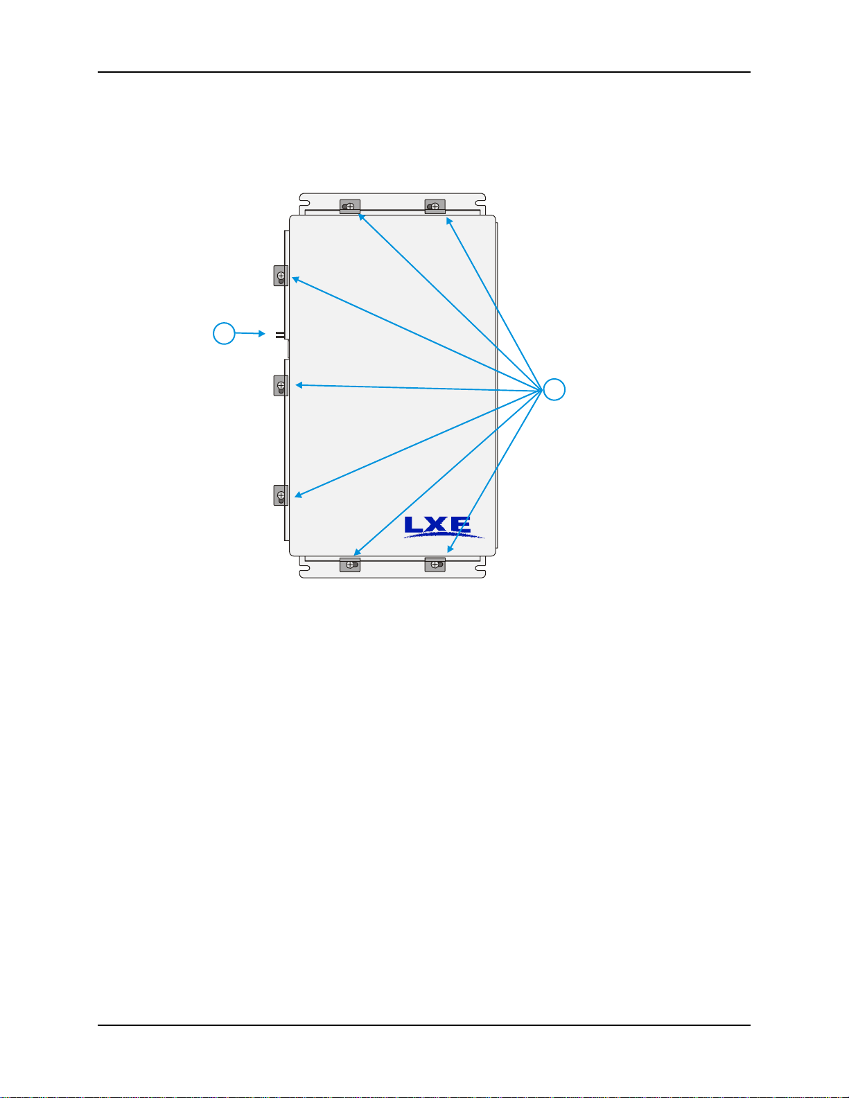
This view represents the front of the Enclosure as mounted on a wall.
2
1. Clips and Screws
1
Figure 1 NEMA Enclosure, Front View
Please note that the AC power and Ethernet connections are on the bottom of the unit when
installed. To preserve the NEMA Type 4 rating, the Enclosure must be mounted with the AC
power and Ethernet connectors on the bottom.
2. Latch for UserSupplied Padlock
E-EQ-NEMARG-F NEMA Type 4 Enclosure Reference Guide
Page 14
6 Components
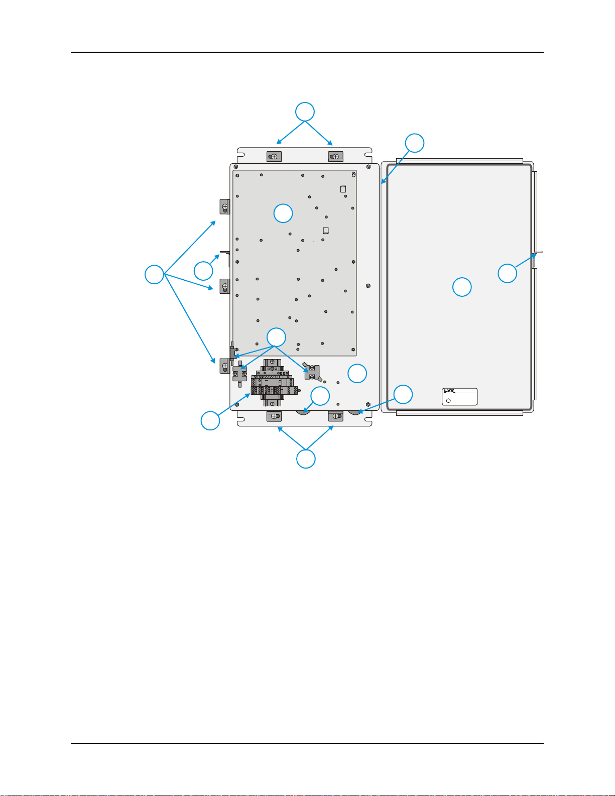
This view represents the interior of the Enclosure with no kits installed.
1
10
3
1
2
2
9
4
5
RAINTIGHT AND WATERTIGHT TYPE 4 INDUSTRIAL
CONTROL PANEL ENCLOSURE SUITABLE FOR
7
8
INSTALLATION IN WET LOCATIONS
U
L
C
®
US
LISTED
E-205841
INDUSTRIAL CONTROL
PANEL ENCLOSURE
ISSUE NO. XXXXXXX
6
1
1. Clips and Screws 6. Terminal Block (Includes Fuse Holder)
2. Latch for User-Supplied Padlock 7. AC Power Inlet
3. AP Mounting Plate 8. Ethernet Cable Inlet
4. Thermostats (Heated Enclosures only) 9. Lid
5. Base Plate 10. Hinge
Figure 2 NEMA Enclosure, Inside View
Note: LXE installed internal wiring is omitted from this diagram for clarity.
NEMA Type 4 Enclosure Reference Guide E-EQ-NEMARG-F
Page 15
Components 7
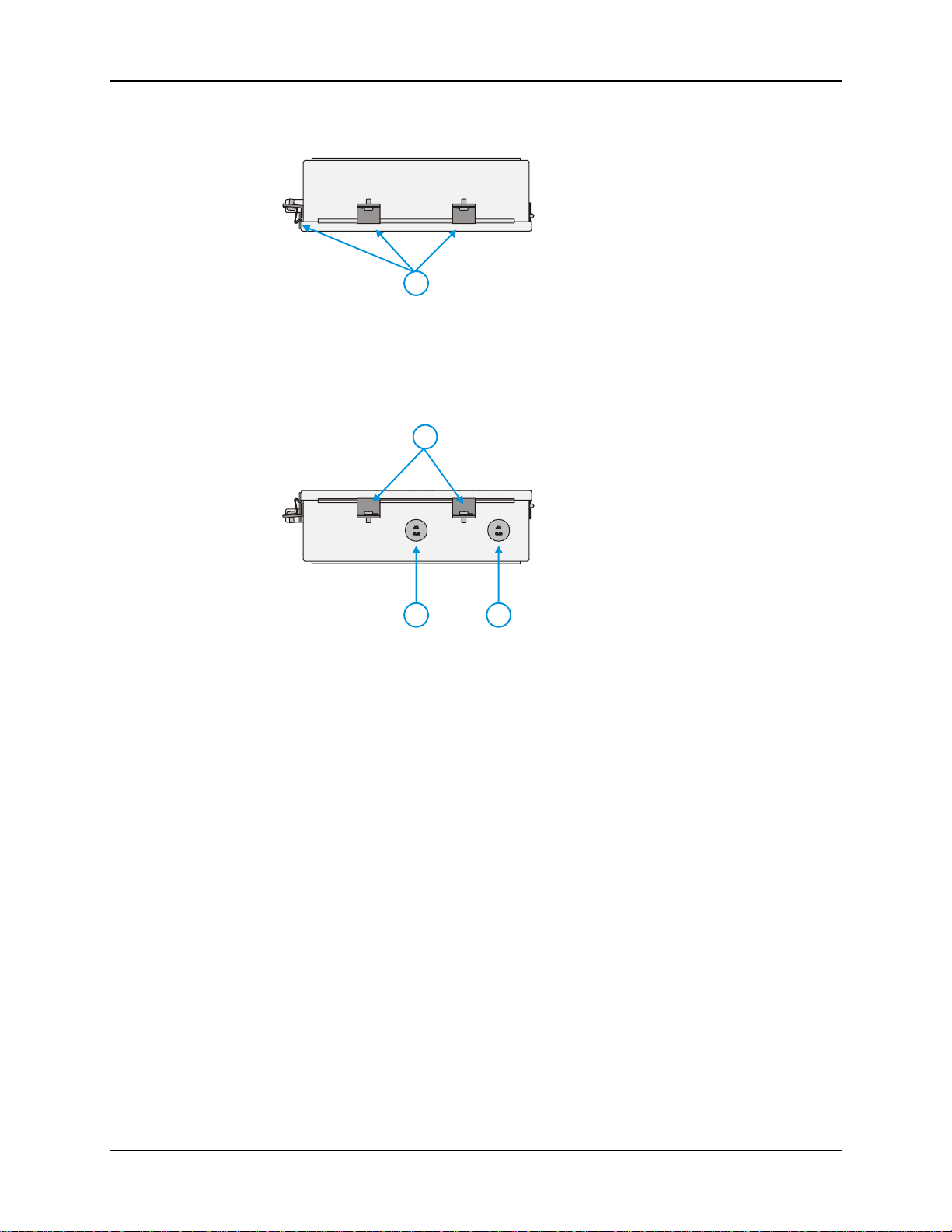
This view represents the top of the Enclosure as mounted on a wall.
1. Clips and Screws
1
Figure 3 NEMA Enclosure, Top View
Please note there are no connectors on the top of the Enclosure.
This view represents the bottom of the Enclosure as mounted on a wall.
1
1. Clips and Screws
2. AC Connector
3. Ethernet Connector
2
Figure 4 NEMA Enclosure, Bottom View
Please note the connectors for AC power and Ethernet cable are on the bottom of the Enclosure.
3
E-EQ-NEMARG-F NEMA Type 4 Enclosure Reference Guide
Page 16
8 Components
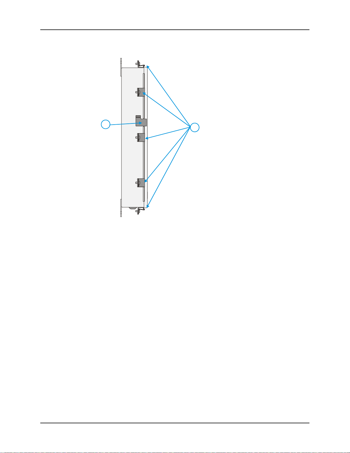
This view represents the left, or latch, side of the Enclosure as mounted on a wall.
2
Figure 5 NEMA Enclosure, Left (Latch side) View
Please note the provision for a user-supplied padlock.
1
1. Clips and Screws
2. Latch for User Supplied
Padlock
NEMA Type 4 Enclosure Reference Guide E-EQ-NEMARG-F
Page 17
Components 9
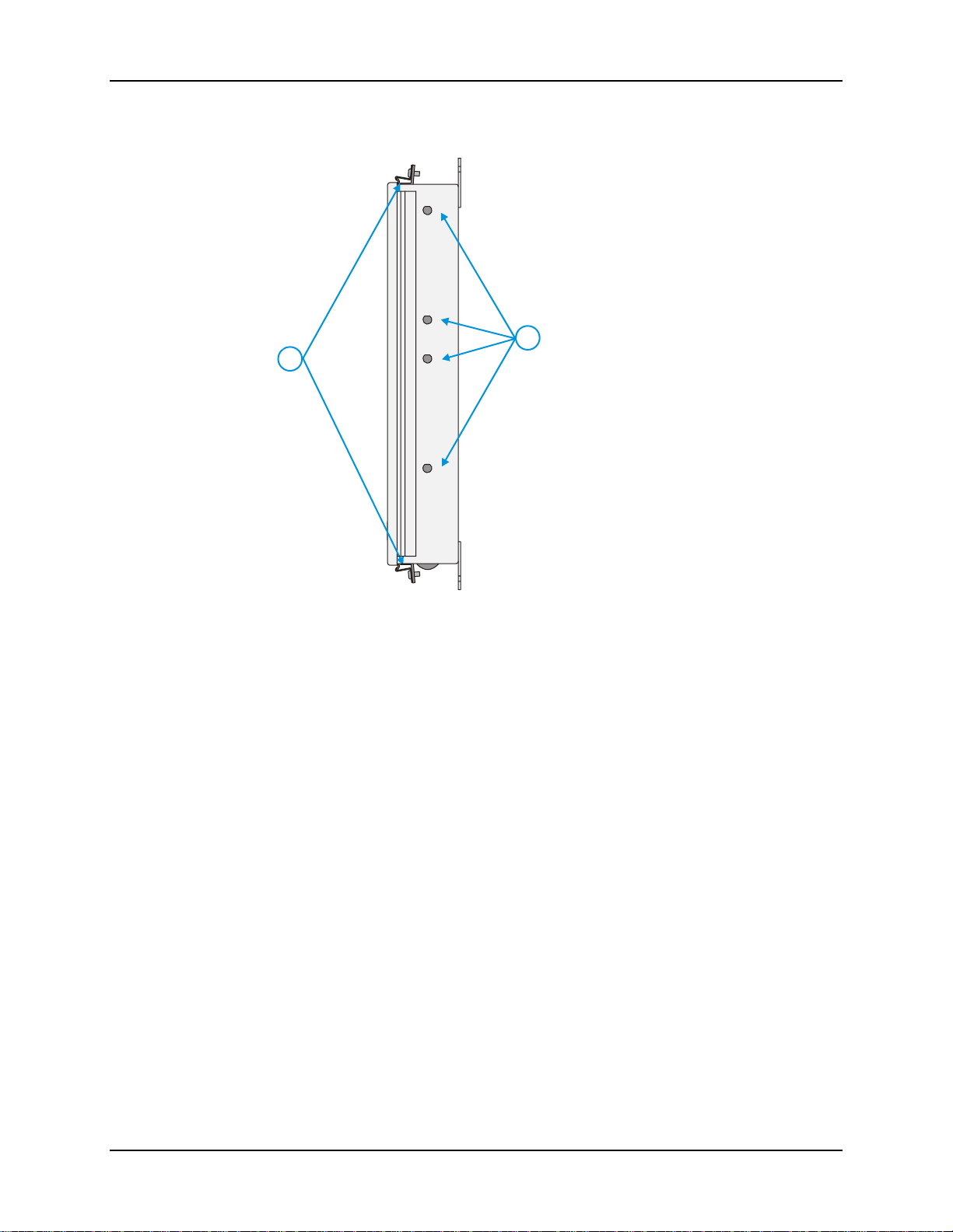
This view represents the right, or hinge side of the Enclosure as mounted on a wall.
2
1. Clips and Screws
1
2. Holes for External
Antennas
Figure 6 NEMA Enclosure, Right (Hinge side) View
Please note the front cover is not removable.
Note: Any unused antenna holes must be securely sealed with provided plugs and hardware.
E-EQ-NEMARG-F NEMA Type 4 Enclosure Reference Guide
Page 18
10 Configuration
Configuration
Please refer to the appropriate section of Appendix B, “Installation Procedure Sheets (non-RoHS)”
or Appendix C, “Installation Procedure Sheets (RoHS)” for details on installing enclosed devices
in the Enclosure.
When to Use This Guide
As the reference for LXE’s NEMA Type 4 Enclosure, this guide provides detailed information on
its installation, features and functionality. Use this reference guide as you would any other source
book -- reading portions to learn about the enclosure, and then referring to it when you need more
information about a particular subject. Always review the instructions in this guide before making
any changes to the installation of the LXE Enclosure.
This chapter, “Introduction”, highlights the features and design of the Enclosure.
Chapter 2, Installation”, details the process of setting up and installing the Enclosure.
Appendix A, “Technical Specifications”, lists the specifications of the Enclosure and enclosed
devices.
Appendix B, “Installation Procedure Sheets (non-RoHS)”, provides copies of the instructions
provided with AP/bridge install kits and lightning suppression install kits for countries that do not
require RoHS compliant items.
Appendix C, “Installation Procedure Sheets (RoHS)”, provides copies of the instructions
provided with AP/bridge install kits and lightning suppression install kits that require RoHS
compliant items.
Document Conventions
This reference guide uses the following document conve nt ions:
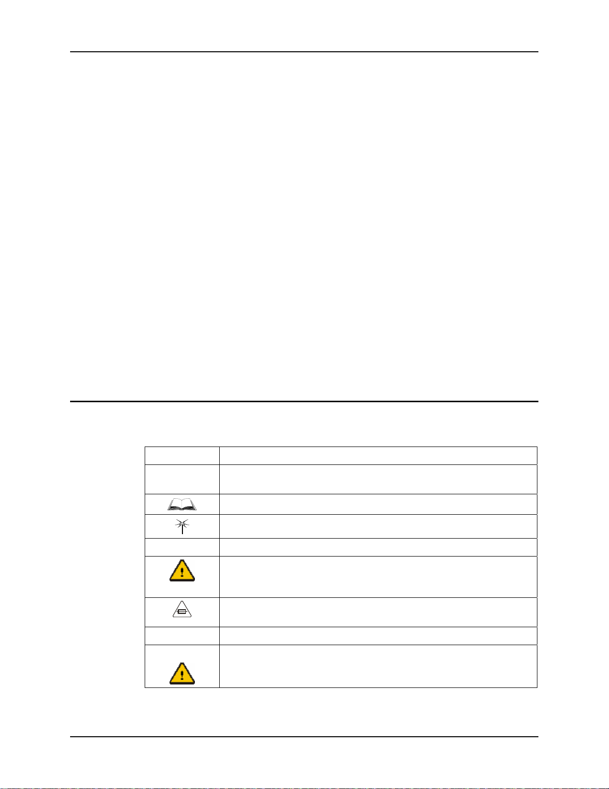
Convention Meaning
“Quotes” Indicates the title of a book, chapter or a section within a chapter (for
ATTENTION
Note: Keyword that indicates immediately relevant information.
example, “Document Conventions”).
Indicates a reference to other documentati on.
Differences in operation or commands due to radio type.
Keyword that indicates vital or pivotal information to follow.
Attention symbol that indicates vital or pivotal information to follow. Also,
when marked on product, means to refer to the manual or operator’s guide.
International fuse replacement symbol. When marked on the product, the
label includes fuse ratings in volts (v) and amperes (a) for the product.
Caution
Keyword that indicates a potentially hazardous situation which, if not
avoided, may result in minor or moderate injury.
NEMA Type 4 Enclosure Reference Guide E-EQ-NEMARG-F
Page 19

Getting Help 11
Getting Help
All LXE manuals are now available on one CD and they can also be viewed/downloaded
from the LXE website. Contact your LXE representative to obtain the LXE Manuals CD.
You can also get help from LXE by calling the telephone numbers listed on the LXE Manuals CD,
in the file titled “Contacting LXE”. This information is also available on the LXE website
www.lxe.com.
Accessories
Install Kits for AP’s and Bridges
Please consult your LXE Representative for information on the following installation kits.
Although some APs and Bridges are obsolete, the Install Kit may still be available. Kits are
available that meet the RoHS compliance standards.
• Install Kit, 6720 or 6723
• Install Kit, 6730/6740
• Install Kit, 6520
• Install Kit, 6540
• Install Kit, 6543
• Install Kit, 6540 & 6543
• Install Kit, 6720 & 6723
• Install Kit, 6730/6740 & 6723
Note: Install kits include brackets, screws, cables, instruction sheet, etc., necessary to install
the enclosed device in the Enclosure. These kits DO NOT include the AP or Bridge.
Please contact your LXE representative for additional information.
Lightning Suppression Kits
Please consult your LXE Representative for information on the following lightning suppression
kits. Kits are available that meet the RoHS compliance standards.
• RF Antenna Surge Suppression
• Ethernet Surge Suppression
• AC Power Surge Suppression, 120V
• AC Power Surge Suppression, 240V
Note: These suppression kits are for use in the NEMA Enclosure ONLY. They are not intended
for use with any other LXE product.
E-EQ-NEMARG-F NEMA Type 4 Enclosure Reference Guide
Page 20

12 Accessories
NEMA Type 4 Enclosure Reference Guide E-EQ-NEMARG-F
Page 21
Chapter 2 Installation
Step 1: Assemble Internal Components
Note: LXE recommends performing the installation of enclosed devices and internal
wiring/cabling before the Enclosure is mounted. These devices should be installed while
the enclosure is laying flat on a workbench. Please note that the enclosure door CAN
NOT be removed.
LXE recommends that installation or removal of access points, bridges or lightning suppression
components be performed on a clean, well-lit surface. When necessary, protect the work surface
and components from electrostatic discharge.
• Follow the instruction sheet provided with the install kit to install each AP/bridge in
the NEMA enclosure using the brackets from the install kit. A copy of the
installation sheet is provided in Appendix B, “Installation Procedure Sheets (nonRoHS)” or Appendix C, “Installation Procedure Sheets (RoHS)”.
• Following the instruction sheet, route any necessary internal AC wires from the
terminal block to the enclosed device(s).
Caution
• Following the instruction sheet, route any necessary internal Ethernet cables.
• Following the instruction sheet, route any necessary RF antenna cables. Remove the
necessary plugs to install external antennas. To maintain the Type 4 rating of the
enclosure, be sure any antenna connectors and plugs for unused antenna holes are
properly secured.
If the NEMA enclosure is heated, all AC wires, RF antenna cables and Ethernet
cables must be secured so they do not come in contact with the back plate. The back
plate can get hot enough to melt the wires/cables when the heater is in use.
E-EQ-NEMARG-F NEMA Type 4 Enclosure Reference Guide
Page 22
14 Step 1: Assemble Internal Components
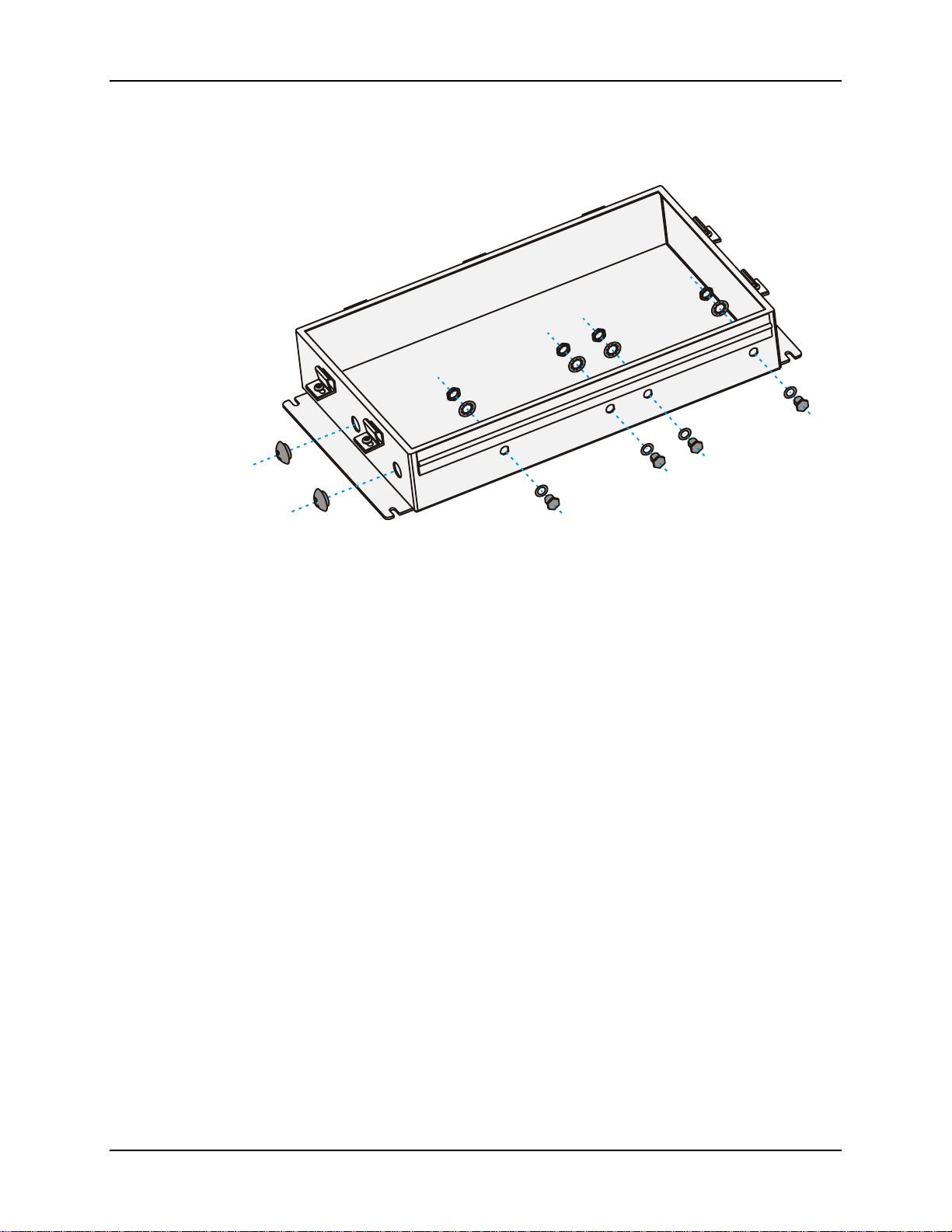
When all internal components are installed, ensure that any unused connection holes are securely
plugged.
Figure 7 Watertight Plugs
Note: Lid, enclosed components and other internal details omitted for clarity.
The NEMA enclosure is ready to be mounted in the desired location.
NEMA Type 4 Enclosure Reference Guide E-EQ-NEMARG-F
Page 23
Step 2: Mount NEMA Enclosure 15
Step 2: Mount NEMA Enclosure
Select the proper location for installation of the Enclosure using the Site Su rvey report provided
by LXE.
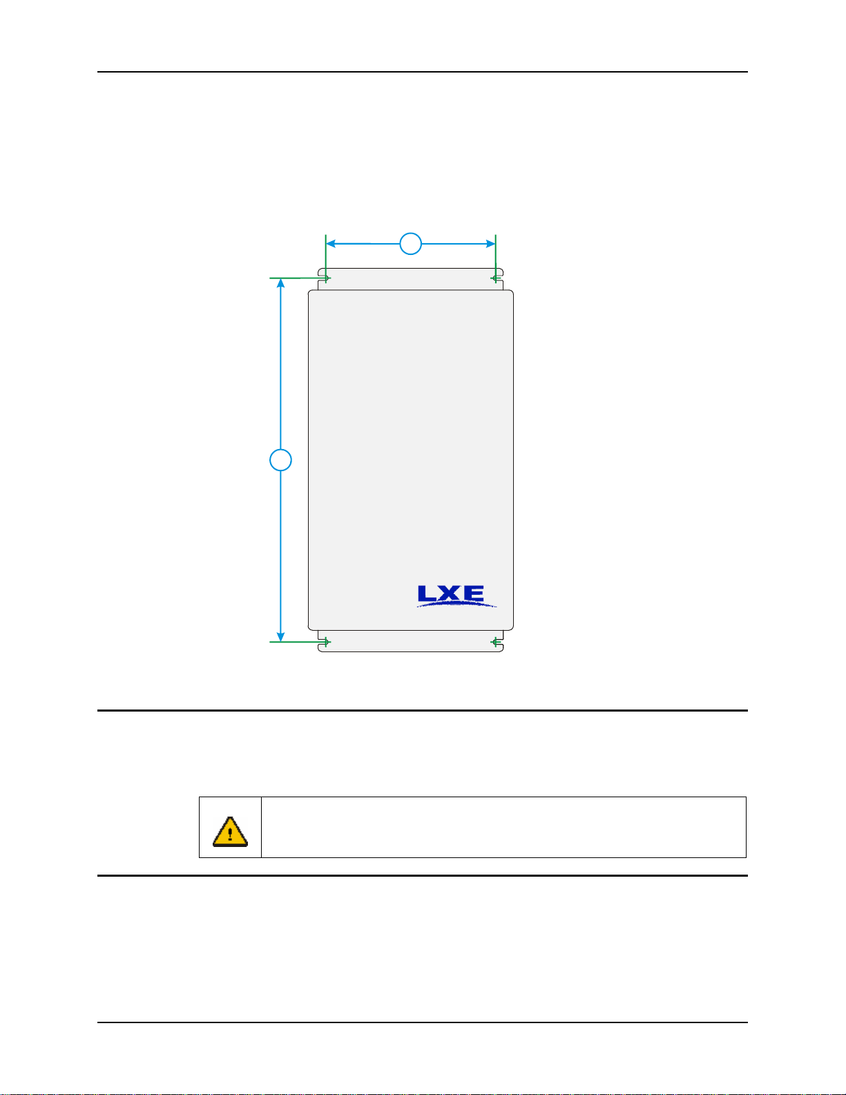
Please refer to the template below for measurements when mounting the Enclosure.
1
1. 11.00” (27.94 cm)
Direct Wall Mount
The Enclosure may be mounted directly on a wall. The Enclosure must be mounted vertically.
The Enclosure has slots for the securing bolts to allow for easy installation. Please refer to the
template above for mounting dimensions
Caution
2
Figure 8 Mounting Template
If the enclosure cannot be attached to wall studs or other surfaces capable of
supporting up to 20 lbs (9 kg), the NEMA enclosure must be attached to a mounting
board. The mounting board must be securely attached to the wall.
2. 23.50” (59.69 cm)
Using a Mounting Board
An appropriate mounting board should be used. LXE reco mmends a ¾ inch (1.90 cm) plywood
mounting board measuring 30” x 40” (76.2 cm x 101.6 cm). The mounting board must be attached
securely to a wall or a ceiling truss or support column using beam clamps, “U” bolts, or other
secure methods. The Enclosure must be mounted vertically. Please refer to the template above for
mounting dimensions.
E-EQ-NEMARG-F NEMA Type 4 Enclosure Reference Guide
Page 24
16 Step 3: Route AC Power and Ethernet
Step 3: Route AC Power and Ethernet
Note: An AC power supply is not need if using Power over Ethernet (PoE) in an unheated
Enclosure.
IMPORTANT
Caution
Caution
IMPORTANT
Caution
LXE’s NEMA Type 4 Enclosure provides electrical cabling for 120V, 60 Hz
electrical power for use in the US and Canada or 240V power for use in
Europe and other locations.
In order to maintain the Type 4 rating of the Enclosure, NEMA rated type 4
connectors must be used when running AC wires or Ethernet cable into the
enclosure.
This Equipment is for installation by qualified service personnel in
accordance with the National Electrical Code, NEC, (NFPA No. 70-1999).
Please install in accordance with the NEC and installation instructions
provided herein and in accordance with any other applicable state or local
code or building codes.
LXE’s NEMA Enclosure is available with optional power surge suppression.
If this option was not ordered, LXE recommends either purchasing the
lightning suppression kit or adding an external provision for surge
protection.
In addition, it may be desirable to add a Uninterruptible Power Supply
(UPS) to the circuit
Risk of electric shock. Disconnect AC electrical branch circuit or DC
power supply before proceeding. Use OSHA LOCK OUT/TAG OUT
procedures for safe and proper isolation of electrical circuits.
Important NEC note: For separation of circuits requirement, please
The AC wiring must be installed by a licensed electrician. Arrange for an electrician to install
conduit to the Enclosure and AC wiring to the AC terminal block observing proper polarity
connections for line, neutral and ground and wire color coding. Maintain as much sepa ration as
possible from other wiring inside the enclosure.
physically route, isolate, and secure the AC supply conductors away from all
low voltage wiring and conductors (all antenn a and data cables). A
minimum 0.25 inch physical separation between AC primary circuit
conductors and all other low voltage wiring is required by the 1999 NEC.
Reference NEC Article 725-54(a)(1), exception no. 2(a).
NEMA Type 4 Enclosure Reference Guide E-EQ-NEMARG-F
Page 25
Step 3: Route AC Power and Ethernet 17
Route the electrical wires to the terminal block.
1. Disconnect power from the electrical circuit before working.
2. Run power to the Enclosure and use a NEMA4 rated connector to route the AC
power cable through the opening located on the bottom left of the enclosure.
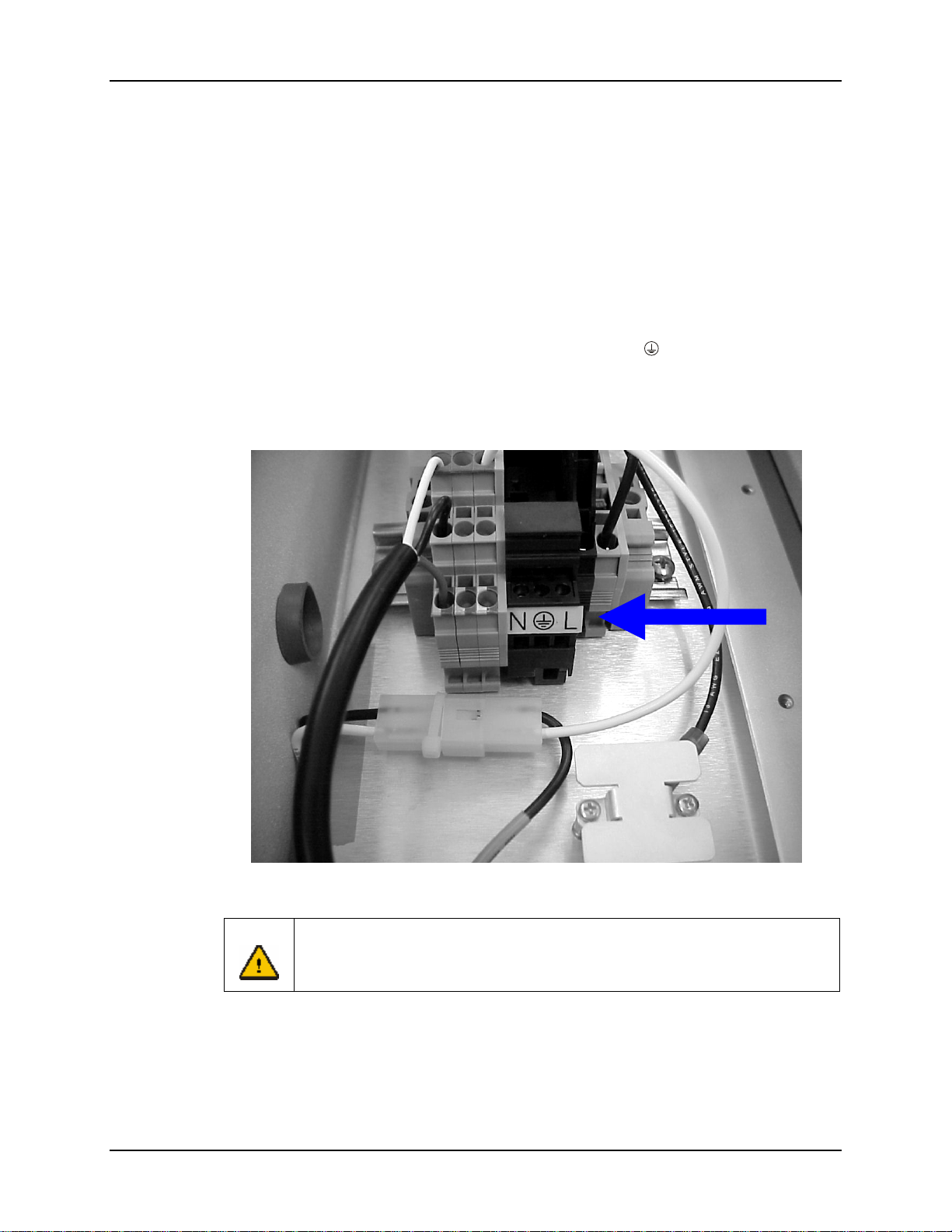
3. Connect the wires to the terminal block, to the terminals shown below, following
established standards:
• Route the line wire to the terminal marked L
• Route the neutral wire to the terminal marked N
• Route the ground (green or green with yellow stripe) wire to the middle
terminal, identified by the “ground” symbol,
4. Run an Ethernet cable (if desired) to the Enclosure and use a NEMA rated connector
to rout the Ethernet cable through the opening located on the bottom right of the
enclosure.
.
Figure 9 Terminal Block Wiring Connections
Caution
If the NEMA enclosure is heated, all AC wires, RF antenna cables and Ethernet
cables must be secured so they do not come in contact with the back plate. The back
plate can get hot enough to melt the wires/cables when the heater is in use.
E-EQ-NEMARG-F NEMA Type 4 Enclosure Reference Guide
Page 26

18 Step 3: Route AC Power and Ethernet
Important Notes
The NEMA Type 4 Enclosure is for installation in accordance with the requirements of the
National Electrical Code, NEC, (NFPA No. 70-1999) and other Building Codes as applicable.
The NEMA Type 4 Enclosure is provided with a protective earth grounding terminal. Please
connect a properly color coded (green or green with yellow stripe) copper ground conductor,
minimum 12 AWG, to the dedicated terminal provided and marked for this purpose.
Note: This grounding conductor must be provided for all installations.
The NEMA Type 4 Enclosure requires a 120V/60Hz or 240V/50-60Hz, single phase, 3 conductor
AC supply circuit as specified within the electrical ratings for the specified enclosed devices. The
maximum supply wire size suitable for connection to the field wiring terminal strip is 12 AWG
stranded or solid copper conductors only. The maximum branch circuit overcurrent protective
device (OCPD) acceptable for use is 20A (ampere) for 120V supply circuits and 10A for 240V
supply circuits.
The enclosed devices are only for connection to electrical supply circuits using a grounded neutral
conductor. It is not approved for use on 240VAC circu its using two line conductors. The second
supply circuit conductor must always be a grounded neutral wire.
The NEMA Type 4 Enclosure requires an AC supply circuit disconnect switch (not provided) for
proper installation. The disconnect switch is required to open both supply conductors (double pole
single throw switch) and, upon installation, should be located in close proximity and within sight
of the NEMA Type 4 Enclosure. The disconnect switch is not permitted to open the protective
earth (ground) conductor to the enclosure.
NEMA Type 4 Enclosure Reference Guide E-EQ-NEMARG-F
Page 27
Step 4: Complete Installation 19
Step 4: Complete Installation
After all connections are complete, close the Enclosure door.
There are seven (7) clips around the edges of the Enclosure lid. Ensure that each clip catches the
lip of the Enclosure lid. Tighten the screw for each clip securely.
If desired, install a user-supplied padlock to prevent unauthorized access to the contents of the
Enclosure.
Once the box is secured, return power to the electrical circuit.
Caution
Fuse Replacement
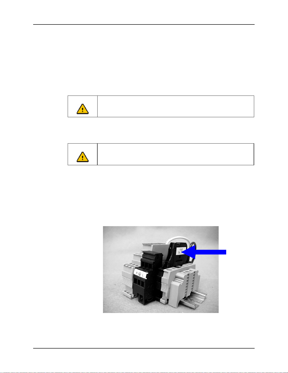
Both the 120V and 240V units use a 250V, 5A Fast Blow fuse.
Caution:
The fuse holder is located on the top of the Terminal Block.
To replace the fuse:
1. Grasp the fuse holder and pull up.
2. Remove the old fuse and replace with a new fuse of the specified capacity
3. Close the fuse holder.
If the Enclosure must be reopened for any reason, the AC power MUST BE
turned off before opening the enclosure.
For continued protection against risk of fire, replace only with the same type
and rating of fuse.
Figure 10 Fuse Holder
E-EQ-NEMARG-F NEMA Type 4 Enclosure Reference Guide
Page 28
20 Completed Installation
Completed Installation
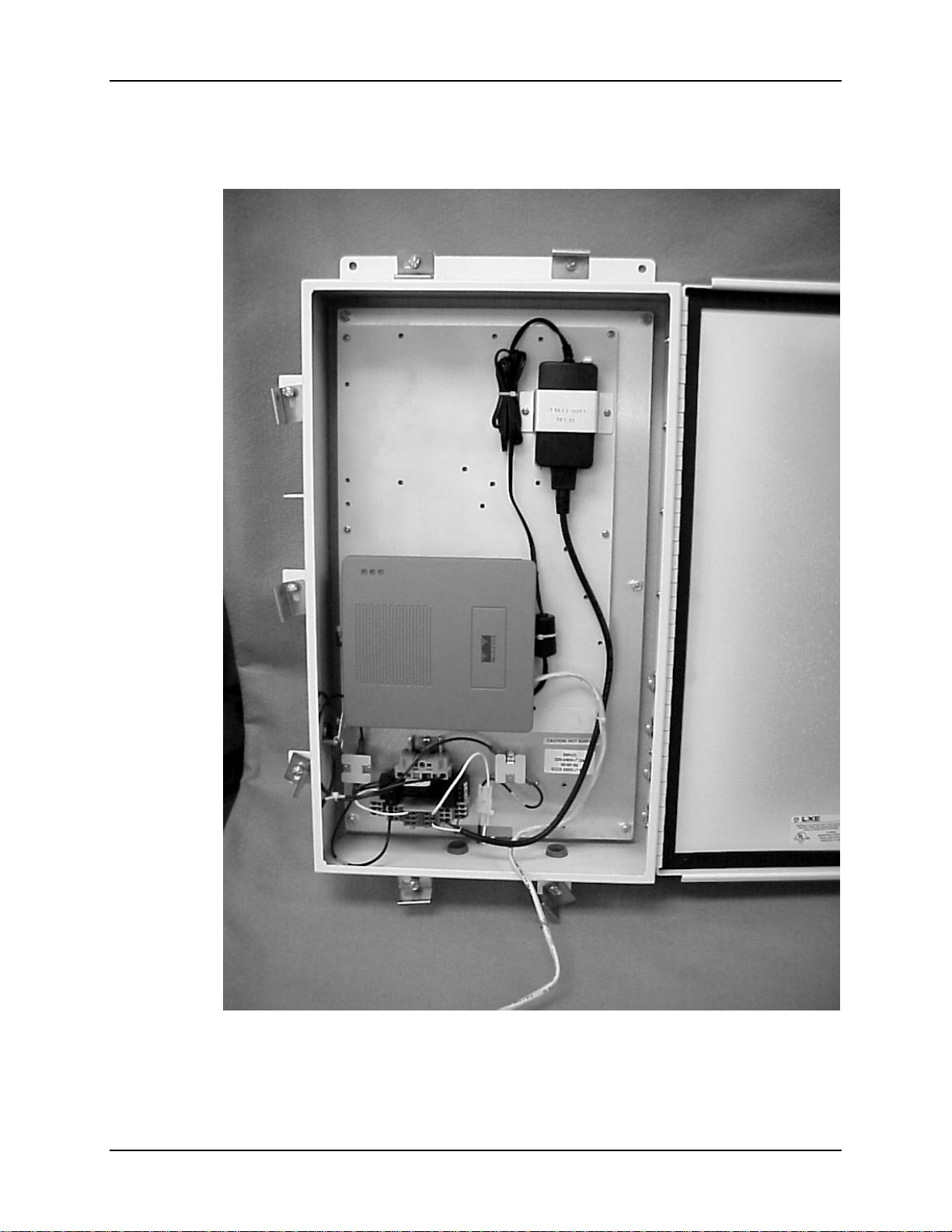
Figure 11 NEMA Enclosure, Typical Installation
Note: AC wiring and Ethernet cabling not shown.
NEMA Type 4 Enclosure Reference Guide E-EQ-NEMARG-F
Page 29
Appendix A Technical Specifications
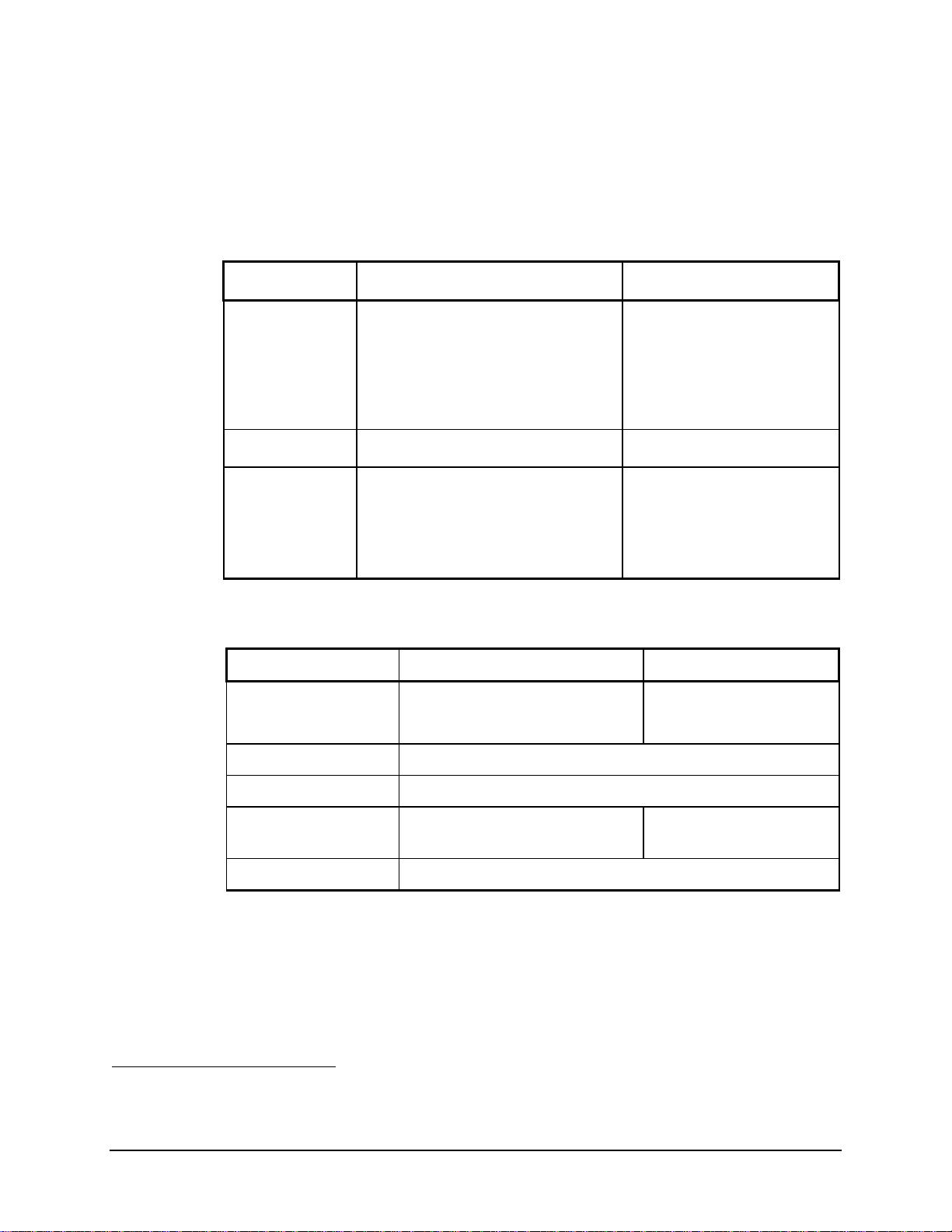
Physical Specifications
Features Specification Comments
External
Connectors/
Interfaces
Weight 19.2 lbs (8.71 kg) Maximum weight
Dimensions Height: 22.02 in (55.93 cm)
AC Power
Data cabling
Mounting holes for up to four external
antennas
Width: 13.3 in (34.00 cm)
Depth: 3.91 in (9.93 cm)
Environmental Specifications
Feature Specification Comments
-30 ºC to 50 ºC (-22 ºF to 122 ºF)
Storage Temperature -40 ºC to 60 ºC (-40 ºF to 140 ºF)
120V or 240V AC, via conduit
Cat 5 Ethernet, via conduit
All dimensions are measured
with no external antennas
installed.
0 ºC to 50 ºC (32 ºF to 122 ºF) 1 Base unit Operating Temperature
1
Base unit with heater
Water, Sand and Dust Type 4 rating
Lightning Protection
Humidity 0% to 95%, non-condensing
1
If internal devices are not rated to 70º C (158º F), the operating temperature must be decreased
accordingly. Enclosed devices assumed to dissipate less than 20W.
Waveform of 8 μs rise time by 20
μs fall time, min imum 10 kA
Optional
E-EQ-NEMARG-F NEMA Type 4 Enclosure Reference Guide
Page 30
22 Enclosed Devices
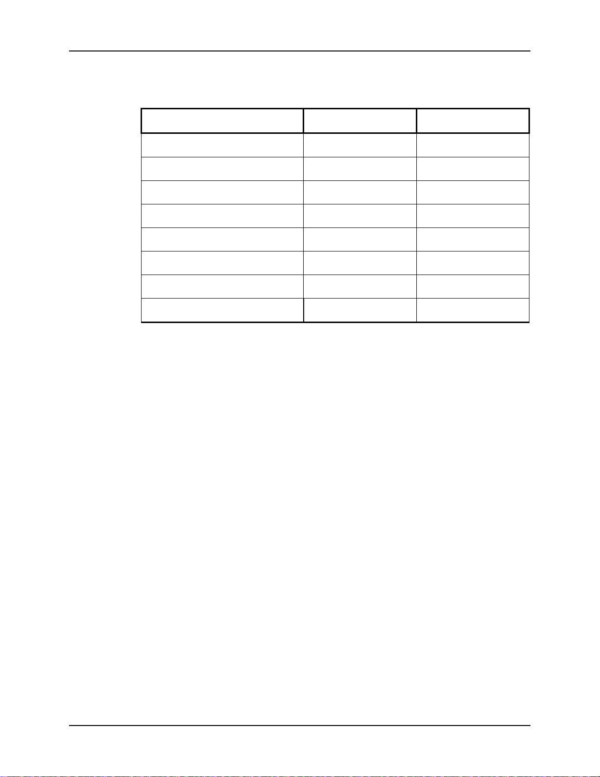
Enclosed Devices
Enclosed Device Power @ 120V Power @ 240V
LXE 6520 AP/Orinoco AP 1000 6.50 W 9.00 W
LXE 6540 AP/Proxim AP 600 5.30 W 8.50 W
LXE 6543 Bridge/Proxim MP.11 5.60 W 8.70 W
LXE 6720 AP/Cisco AP 350 7.20 W 8.70 W
LXE 6723 Bridge/Cisco Bridge 350 6.90 W 7.50 W
LXE 6730/Cisco AP 1200 802.11b 7.20 W 8.50W
LXE 6740/Cisco AP 1200 802.11g 7.20 W 8.50W
AC Heater 261.0 W 291.0 W
Notes: Enclosed devices are assumed to be rated for 70º C (158º F). If enclosed devices are not
rated for this temperature, the maximum temperature for the Enclosure must be adjusted
accordingly.
The power requirement for enclosed Access Points and Bridges is 120 or 240V AC @ 1.0
Amp Maximum.
Enclosed devices should dissipate less than 20W
Some of the network products (AP’s and Bridges) in the table above are obsolete.
NEMA Type 4 Enclosure Reference Guide E-EQ-NEMARG-F
Page 31
Revision History 23
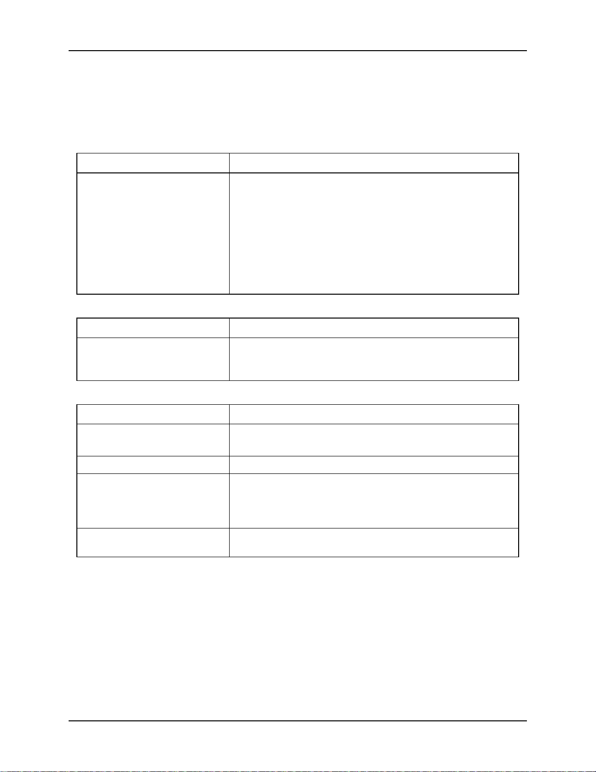
Revision History
Revision A, Initial Release: November 2003
Revision B: February 2004
Section Explanation
Appendix B – Installation
Procedure Sheets
Revision C: May 2004
Section Explanation
Appendix B – Installation
Procedure Sheets
Revision D: August 2005
Section Explanation
Front cover Updated with 2005 LXE logo.
Replaced the Revision A of the following Installation Procedure Sheets
with Revision B:
159084-0001
159085-0001
159086-0001
159087-0001
159088-0001
159089-0001
159128-0001
159333-0001
Replaced the Revision A of the following Installation Procedure Sheet
with Revision B:
159083-0001
Updated notices and copyrights.
Entire Manual Updated all images with LXE logo to reflect the 2005 LXE logo.
Chapter 1 – Introduction Added 6740 to “Enclosed Devices” section and removed obsolete 6540
and 6543.
Updated “Accessories” listing to include 6740 and remove 6540 and
6543.
Appendix A – Technical
Specifications
Updated “Enclosed Devices” section to include 6740 and remove 6540
and 6543.
E-EQ-NEMARG-F NEMA Type 4 Enclosure Reference Guide
Page 32
24 Revision History
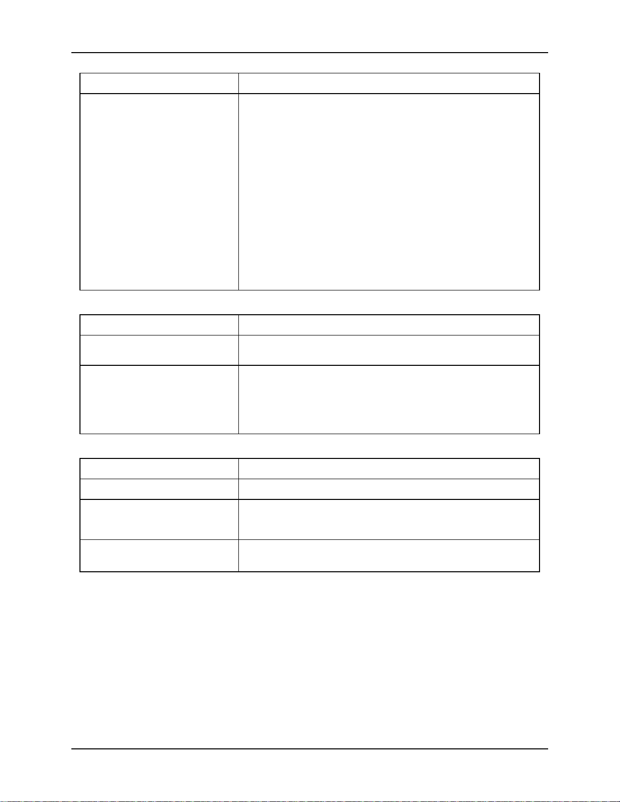
Section Explanation
Appendix B – Installation
Procedure Sheets
Revision E: April 2006
Section Explanation
Appendix A – Technical
Specifications
Appendix B – Installation
Procedure Sheets
Updated “Introduction” section.
Replaced the Revision B of the following Installation Procedure Sheets
with Revision C:
Removed the following Installation Procedure Sheets for obsolete
equipment:
Note: Installation Procedure Sheets for obsolete equipment can be
Added “Revision History”.
Updated “Introduction” section.
Replaced the Revision B of the following Installation Procedure Sheet
with Revision C:
159087-0001
159089-0001
159128-0001
159084-0001
159085-0001
159086-0001
found in the archive section of the LXE ServicePass website.
The archive copy of this manual includes these installation
sheets.
159088-0001
Revision F: August 2006
Section Explanation
Chapter 1 – Introduction Updated accessories listing.
Appendix B – I nstallation
Procedure Sheets
Appendix C – Installation
Procedure Sheets (RoHS)
Renamed to Appendix B, “Installation Procedure Sheets (non-RoHS).
Revised section: “Introduction”.
Added new appendix.
NEMA Type 4 Enclosure Reference Guide E-EQ-NEMARG-F
Page 33

Appendix B Installation Procedure Sheets (non-RoHS)
Introduction
When an Install Kit is purchased for an enclosed device, an Installation Procedure sheet is
included. For reference, those installation sheets are also included in this appendix.
Notes: The installation kit instructions in this appendix are for countries that do not require
RoHS approved products. Please see Appendix C, Installation Procedures Sheets
(RoHS)”, for instructions on installation kits for countries that require RoHS approved
products.
Some of the network products (AP’s and Bridges) mentioned in this document are
obsolete. LXE continues to offers kits to mount these devises as a service to our
customers.
6520 Installation Kit Instructions
Please refer to 159083-0001, “Installation Procedure, LXE Model 6520 AP (Orinoco AP1000)
NEMA 4 Enclosure”, Rev. B.
6540 Installation Kit Instructions
Please refer to 159084-0001, “Installation Procedure, LXE Model 6540 AP (Proxim AP600)
NEMA 4 Enclosure”, Rev. B.
6543 Installation Kit Instructions
Please refer to 159085-0001, “Installation Procedure, LXE Model 6543 Bridge (Proxim MP11)
NEMA 4 Enclosure”, Rev. B.
6540 and 6543 Installation Kit Instructions
Please refer to 159086-0001, “Installation Procedure, LXE Model 6543 (Proxim MP11) & LXE
Model 6540 AP (Proxim AP600) NEMA 4 Enclosure”, Rev. B.
6720 Installation Kit Instructions
Please refer to 159087-0001, “Installation Procedure, LXE Mo del 6720 AP (Cisco 350AP) NEMA
4 Enclosure”, Rev. C.
6730 Installation Kit
Please refer to 159088-0001, “Installation Procedure, LXE Model 6730 AP (Cisco 1200AP)
NEMA 4 Enclosure”, Rev. C.
Note: Use this instruction sheet when installing an LXE Model 6740 AP.
E-EQ-NEMARG-F NEMA Type 4 Enclosure Reference Guide
Page 34

26 Introduction
6730 and 6723 Installation Kit Instructions
Please refer to 159089-0001, “Installation Procedure, LXE Model 672 3 Bridge ( Cisco 350 Br idge)
& LXE Model 6730 AP (Cisco 1200AP) NEMA 4 Enclosure”, Rev. C.
Note: Use this instruction sheet when installing an LXE Model 6740 AP with an LXE Model
6723 Bridge.
6720 and 6723 Installation Kit Instructions
Please refer to 159128-0001, “Installation Procedure, LXE Model 672 3 Bridge ( Cisco 350 Br idge)
& LXE Model 6720 AP (Cisco 350AP) NEMA 4 Enclosure”, Rev. C.
Lightning Suppression Kit
Please refer to 159333-0001, “Installation Procedure For Lightning Suppression Accessories”,
Rev. B for installation of the following:
• RF ANT Surge Suppressor
• Ethernet Surge Suppression
• Power Supply Surge Suppression, 120V
• Power Supply Surge Suppression, 240V
NEMA Type 4 Enclosure Reference Guide E-EQ-NEMARG-F
Page 35

Installation Procedure, LXE Model 6520 AP (non-RoHS)
159083-0001
Rev. B
INSTALLATION PROCEDURE
LXE Model 6520 AP, Orinoco AP 1000
NEMA 4 ENCLOSURE
159083-0001 Rev. B Page 1 of 7
E-EQ-NEMARG-F NEMA Type 4 Enclosure Reference Guide
Page 36
28 Installation Procedure, LXE Model 6520 AP (non-RoHS)
Qty
Qty
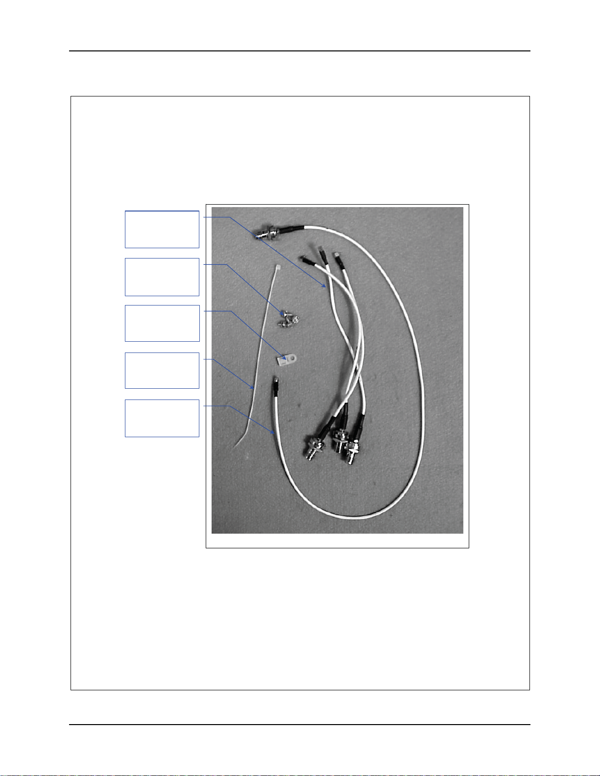
1. Remove the hardware package from the enclosure.
2. Remove contents and verify the quantities. See figure 1.
Antenna Cable
(155724-0001)
Qty. 3
#8-32 Screw,
1/4”long. Qty 4
(137646-0804)
Hardware Package
Nylon Tie Down
(703006-0000)
. 1
8” Nylon Tie
(703028-0000)
. 2
Antenna Cable
(155723-0001)
Qty. 1
Figure 1
159083-0001 Rev. B Page 2 of 7
NEMA Type 4 Enclosure Reference Guide E-EQ-NEMARG-F
Page 37
Installation Procedure, LXE Model 6520 AP (non-RoHS) 29
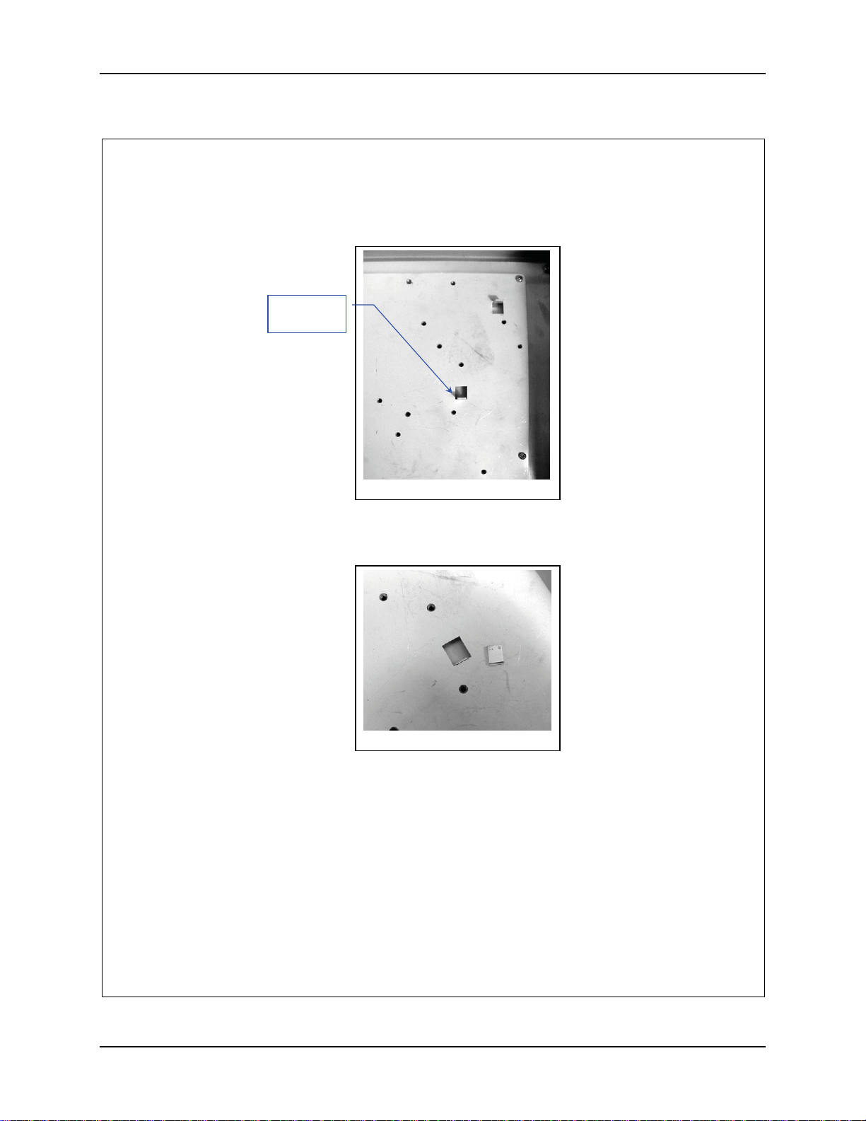
3. Remove the locating tab from the AP Mounting Plate. See figures 2 and 3.
Remove
this Tab.
Figure 2
4. Break the tab off by bending back and forth with a pair of pliers. Discard the
tab.
Figure 3
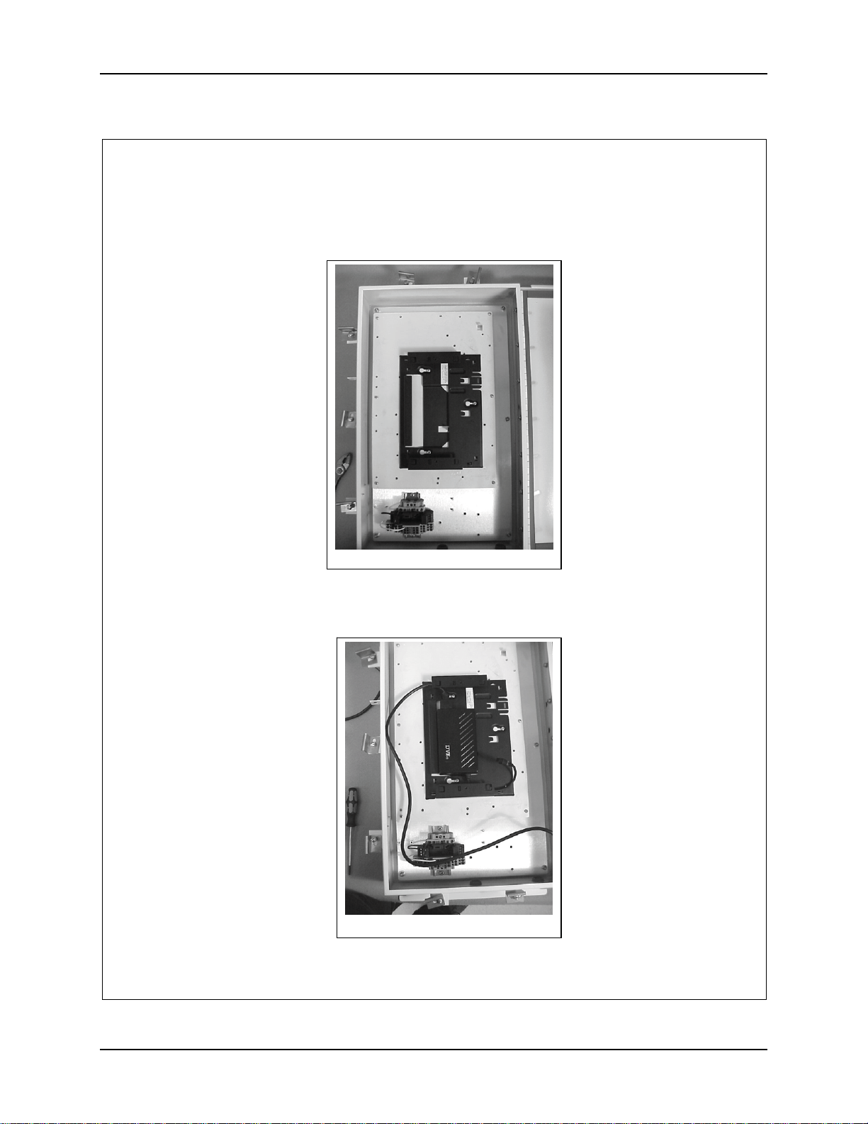
5. Locate the Orinoco AP 1000 mounting bracket on the AP Mounting Plate, see
figure 4.
159083-0001 Rev. B Page 3 of 7
E-EQ-NEMARG-F NEMA Type 4 Enclosure Reference Guide
Page 38
30 Installation Procedure, LXE Model 6520 AP (non-RoHS)
6. Secure the AP Mounting Bracket to the AP Mounting Plate with three (3) 832 screws. See figure 4.
Figure 4
7. Plug the power cord (supplied with the AP) into the power brick.
8. Insert the power brick into the bracket. See figure 5.
Figure 5
159083-0001 Rev. B Page 4 of 7
NEMA Type 4 Enclosure Reference Guide E-EQ-NEMARG-F
Page 39
Installation Procedure, LXE Model 6520 AP (non-RoHS) 31
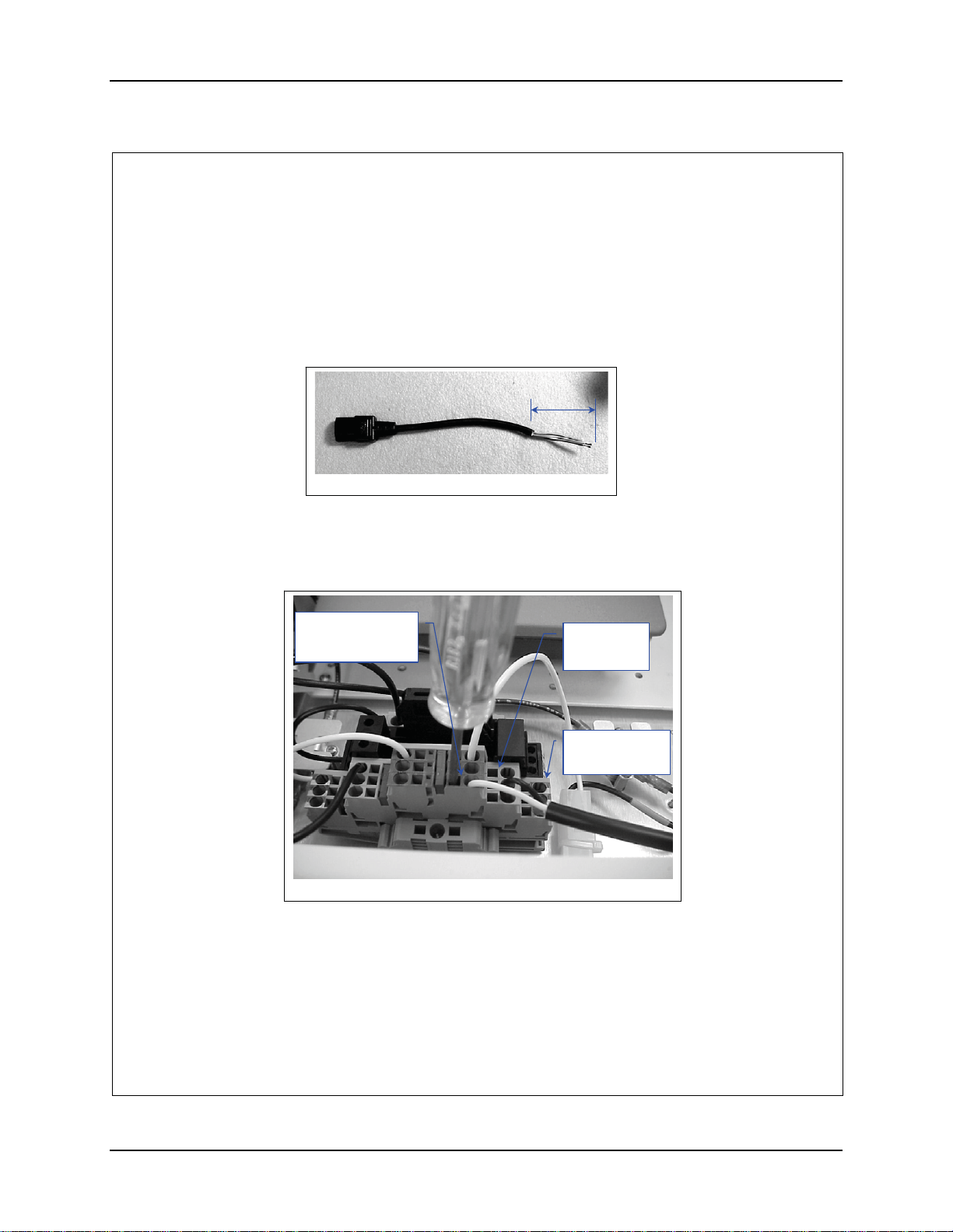
9. Route the power cord to the terminal block.
10. Cut the cord and discard the male end.
11. Remove at least 2” inches of the outer covering from the cut end of each cord.
See figure 6.
2”
Figure 6
12. Remove 0.4” (10 mm) of the insulation from each conductor.
13. Insert the conductors of the cord into the terminal block on the LEFT side.
Neutral (marked blue) Live (unmarked) Ground to Ground (marked green).
See figure 7.
Neutral
Marked Blue
Figure 7 Right side connection shown.
Live
Unmarked
Ground
Marked Green
159083-0001 Rev. B Page 5 of 7
E-EQ-NEMARG-F NEMA Type 4 Enclosure Reference Guide
Page 40
32 Installation Procedure, LXE Model 6520 AP (non-RoHS)
g
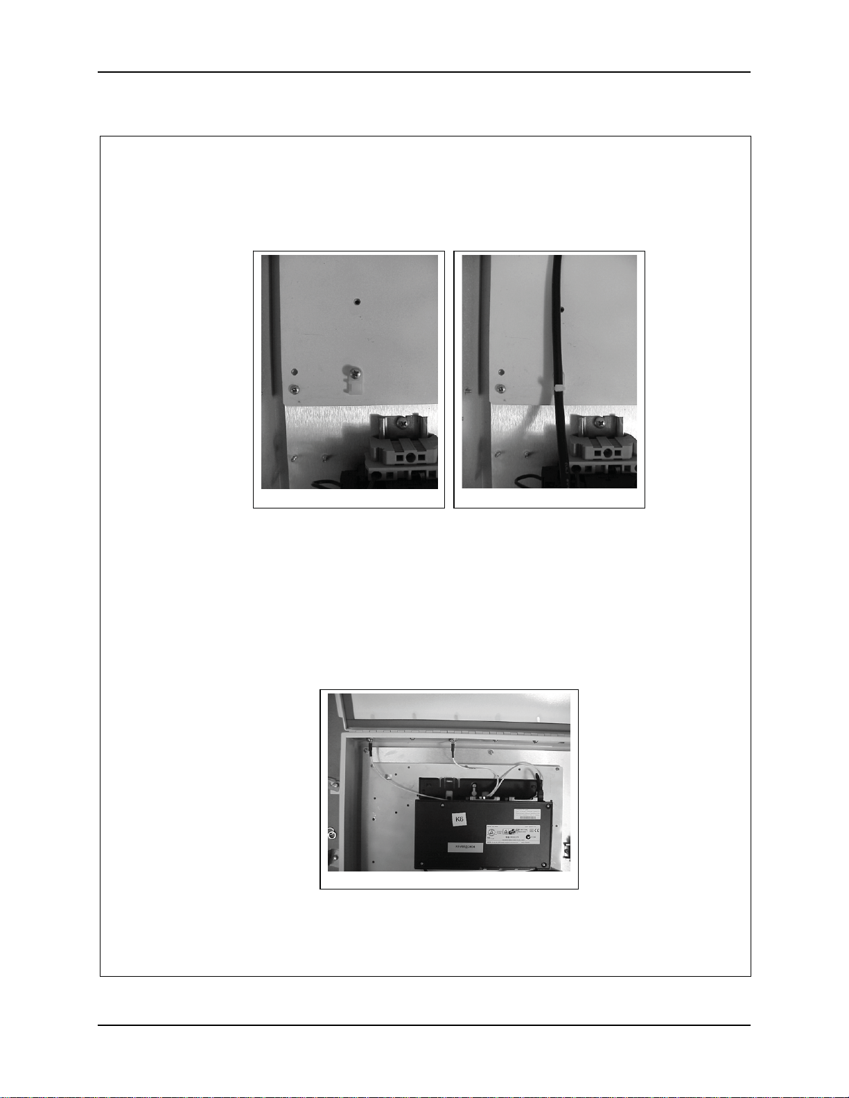
14. Install the nylon tie down on the AP Mounting Plate. Secure it with an 8-32
screw. See figure 8.
Figure 8
15. Secure the power cord to the tie down with the 8” nylon cable tie. See figure
8a. Pull it tight and trim.
16. Remove the two (2) plugs closest to the top, located on the hinge side of the
enclosure.
17. Insert the long antenna cable, 155723-0001 in the FIRST opening from the
top of the enclosure. See figure 9. Secure it with the lock washer and nut.
18. Route the cable to the radio closest to the top of the AP. Connect it to the
radio. See figure 9.
ure 9
Fi
Figure 8a
159083-0001 Rev. B Page 6 of 7
NEMA Type 4 Enclosure Reference Guide E-EQ-NEMARG-F
Page 41
Installation Procedure, LXE Model 6520 AP (non-RoHS) 33
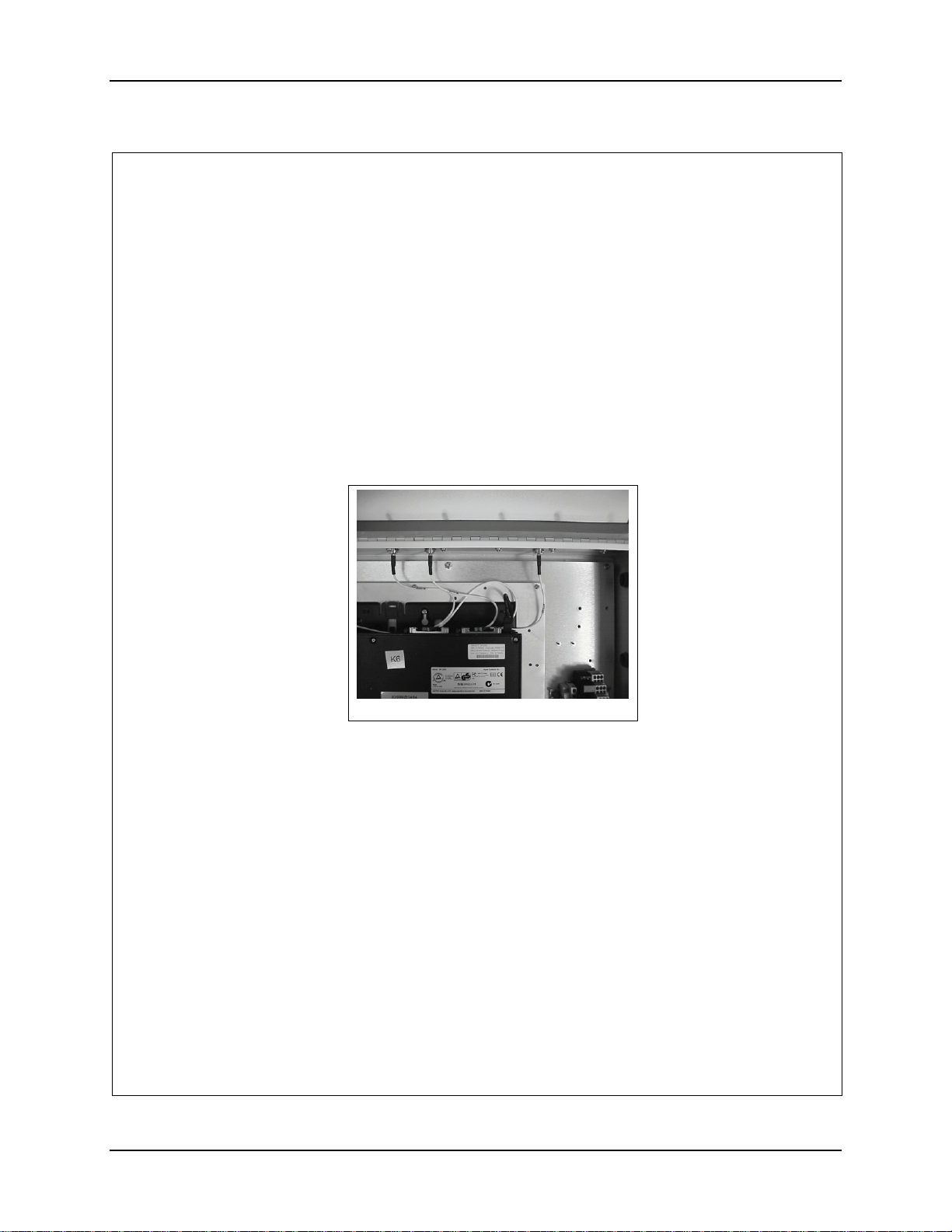
19. Insert an antenna cable, 155724-0001, in the SECOND opening from the top
of the enclosure. See figure 9. Secure it with the lock washer and nut.
20. Route the cable to the radio closest to the top of the AP. Connect it to the
radio. See figure 9.
21. If more than one radio is installed, remove the two (2) remaining plugs and
insert an antenna cable, 155724-0001, in the THIRD and FOURTH openings
from the top of the enclosure. See figure 10. Secure it with the lock washer
and nut.
22. Route the cables to the other radio of the AP. Connect it to the radio. See
figure 10.
Figure 10
23. Connect power and data cables per installation manual.
159083-0001 Rev. B Page 7 of 7
E-EQ-NEMARG-F NEMA Type 4 Enclosure Reference Guide
Page 42

34 Installation Procedure, LXE Model 6520 AP (non-RoHS)
NEMA Type 4 Enclosure Reference Guide E-EQ-NEMARG-F
Page 43
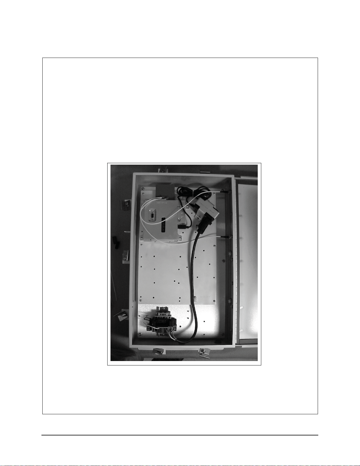
Installation Procedure, LXE Model 6540 AP (non-RoHS)
159084-0001
Rev. B
INSTALLATION PROCEDURE
LXE Model 6540 AP, Proxim AP600
NEMA 4 ENCLOSURE
159084-0001 Rev. B Page 1 of 8
E-EQ-NEMARG-F NEMA Type 4 Enclosure Reference Guide
Page 44
36 Installation Procedure, LXE Model 6540 AP (non-RoHS)
Qty
Qty
Qty
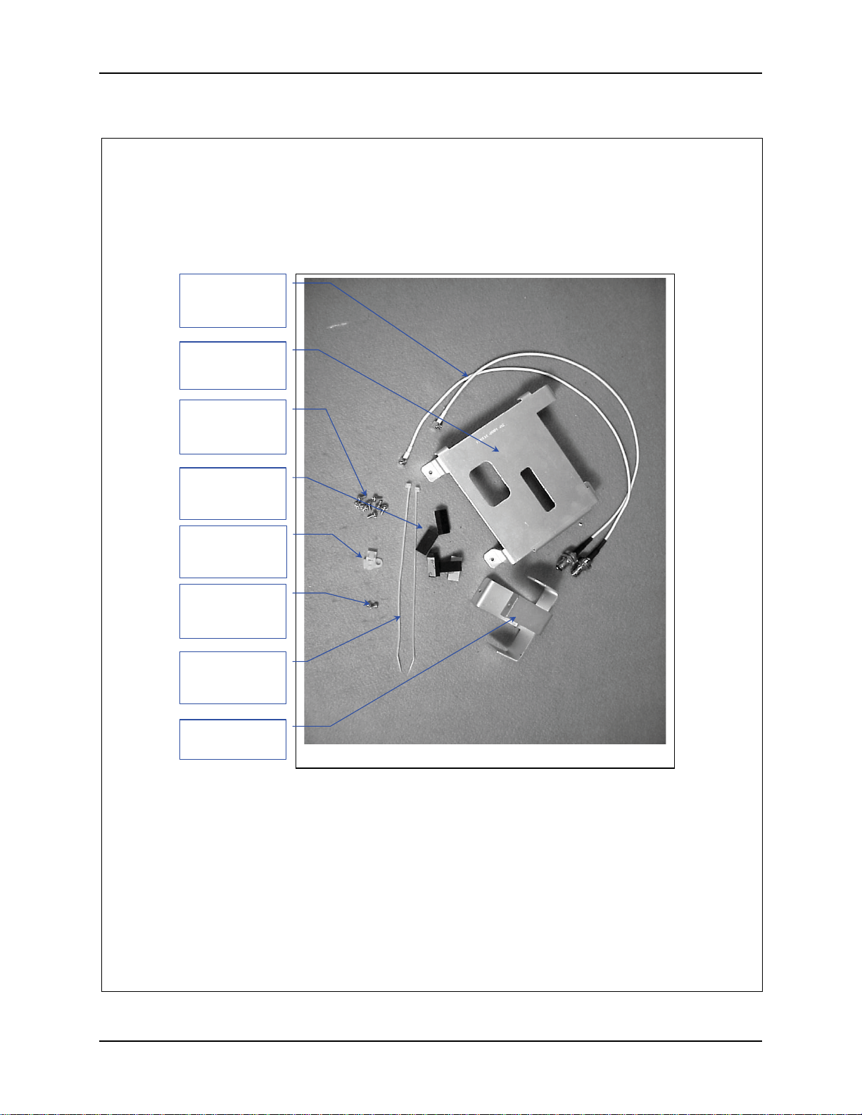
1. Remove the hardware Package from the enclosure.
2. Remove contents and verify the quantities. See figure 1.
Antenna Cable
(159078-0001)
Qty. 2
Bracket, Qty. 1
(1589348-0001)
#6-32 Screw,
5/16”long. Qty 8
(137646-0606)
Pad, Foam
(155154-0001)
. 5
Nylon Tie Down
(703006-0000)
. 2
#4-40 Screw,
1/4”long. Qty 2
(137646-0404)
8” Nylon Tie
(703028-0000)
. 2
Bracket, Qty. 1
(158937-0001)
Hardware Package
Figure 1
159084-0001 Rev. B Page 2 of 8
NEMA Type 4 Enclosure Reference Guide E-EQ-NEMARG-F
Page 45
Installation Procedure, LXE Model 6540 AP (non-RoHS) 37
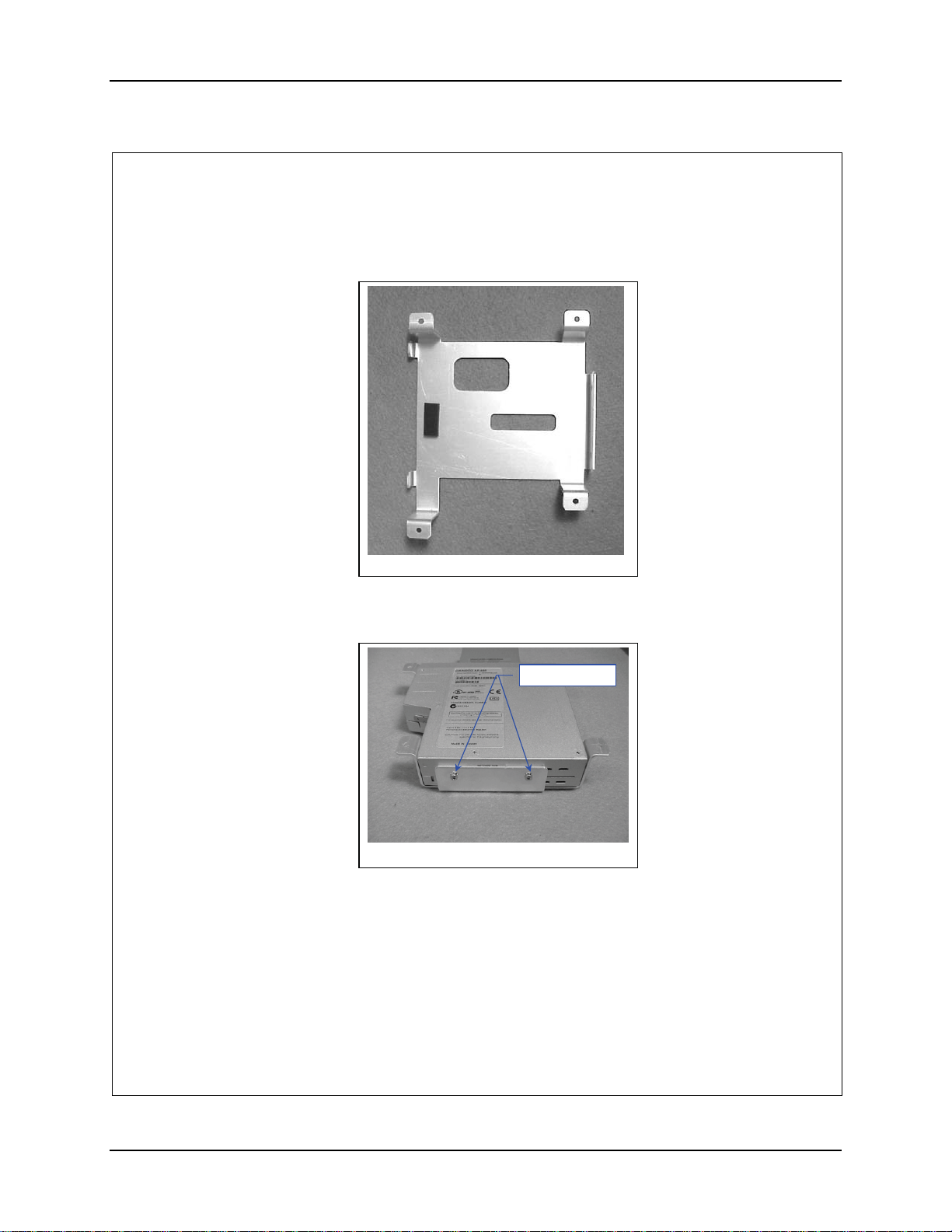
3. Prep the Bracket to accept the AP. Remove the adhesive backing and apply a
foam pad, 155154-0001 to bracket, 158941-0001 as shown in figure 2.
Figure 2
4. Insert the AP top first into the bracket.
5. Secure the AP with the two (2) 4-40 screws. See figure 3.
-
Figure 3
6. Locate the AP, secured in the bracket, on the AP Mounting plate.
159084-0001 Rev. B Page 3 of 8
E-EQ-NEMARG-F NEMA Type 4 Enclosure Reference Guide
Page 46
38 Installation Procedure, LXE Model 6540 AP (non-RoHS)
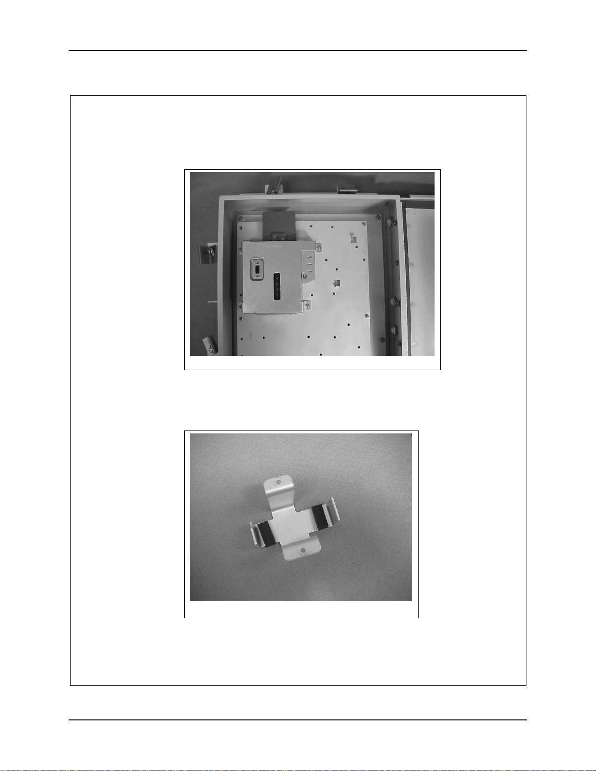
7. Secure the AP to the AP Mounting Plate with four (4) 6-32 screws.
Figure 4
8. If the AP is going to be powered over Ethernet, skip to step 22.
9. Remove the adhesive backing and apply two of the foam pad to bracket,
158937-0001 as shown in figure 5.
Figure 5
159084-0001 Rev. B Page 4 of 8
NEMA Type 4 Enclosure Reference Guide E-EQ-NEMARG-F
Page 47
Installation Procedure, LXE Model 6540 AP (non-RoHS) 39
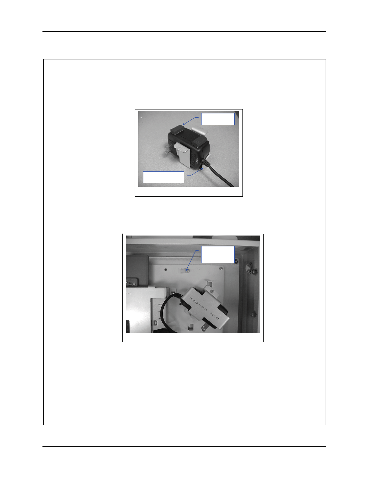
10. Position the AC power Transformer in the bracket with the output cord near
the notched tab on the bracket. See figure 6.
Foam Pads
Notched Tab
Figure 6
11. Remove the adhesive backing and apply the remaining two (2) foam pads to
the transformer, as shown in figure 6
12. Locate the transformer and bracket on the AP Mounting Plate. See figure 7.
Cable Tie
Down
Figure 7
13. Secure the bracket with two (2) 6-32 screws.
14. Install a cable tie down on the AP Mounting Plate as shown in figure 7.
15. Plug the power cord in to the AP.
159084-0001 Rev. B Page 5 of 8
E-EQ-NEMARG-F NEMA Type 4 Enclosure Reference Guide
Page 48
40 Installation Procedure, LXE Model 6540 AP (non-RoHS)
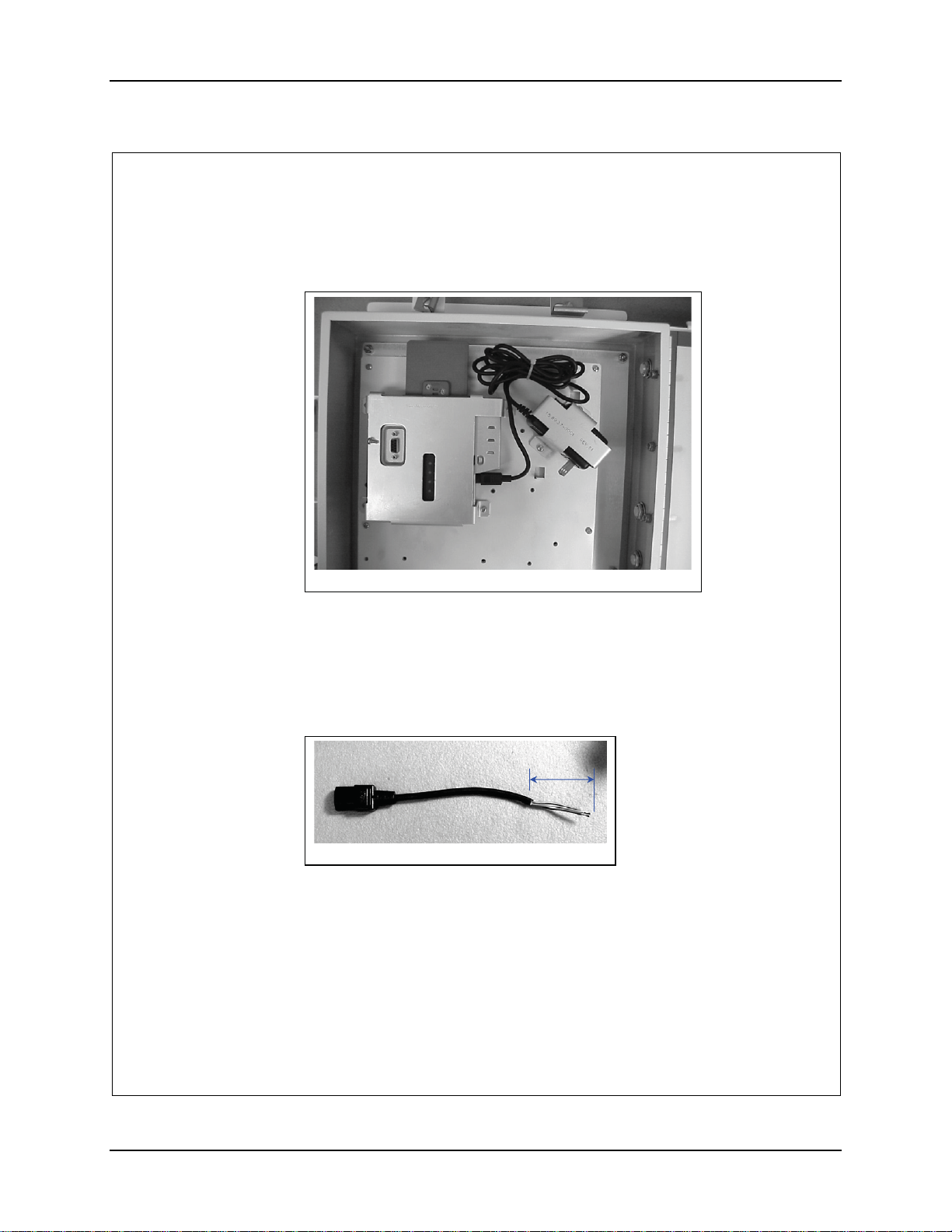
16. Bundle the loose cord up and secure it with an 8” nylon cable tie. See figure
8.
Figure 8
17. Obtain a female power cord (Supplied Locally)
18. Plug the cord into the power transformer and route it to the terminal block.
19. Cut the cord and remove at least 2” inches of the outer covering from the cut
end of the cord. See figure 9.
2”
Figure 9
20. Remove 0.4” (10 mm) of the insulation from each conductor.
159084-0001 Rev. B Page 6 of 8
NEMA Type 4 Enclosure Reference Guide E-EQ-NEMARG-F
Page 49
Installation Procedure, LXE Model 6540 AP (non-RoHS) 41
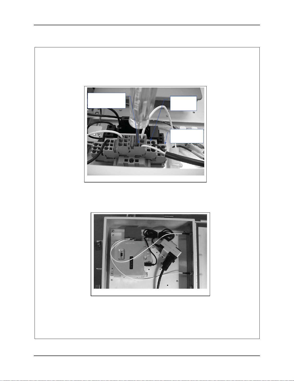
21. Insert the conductors into the terminal block. Neutral (marked blue) Live
(unmarked) Ground to Ground (marked green). See figure 10.
Neutral
Marked Blue
Figure 10
22. Remove the two (2) plugs located on the hinge side of the enclosure closest to
the top.
23. Route the antenna cables as shown in figure 10.
Live
Unmarked
Ground
Marked Green
Figure 11
24. Insert the antenna cable connectors in the holes and secure them.
159084-0001 Rev. B Page 7 of 8
E-EQ-NEMARG-F NEMA Type 4 Enclosure Reference Guide
Page 50
42 Installation Procedure, LXE Model 6540 AP (non-RoHS)
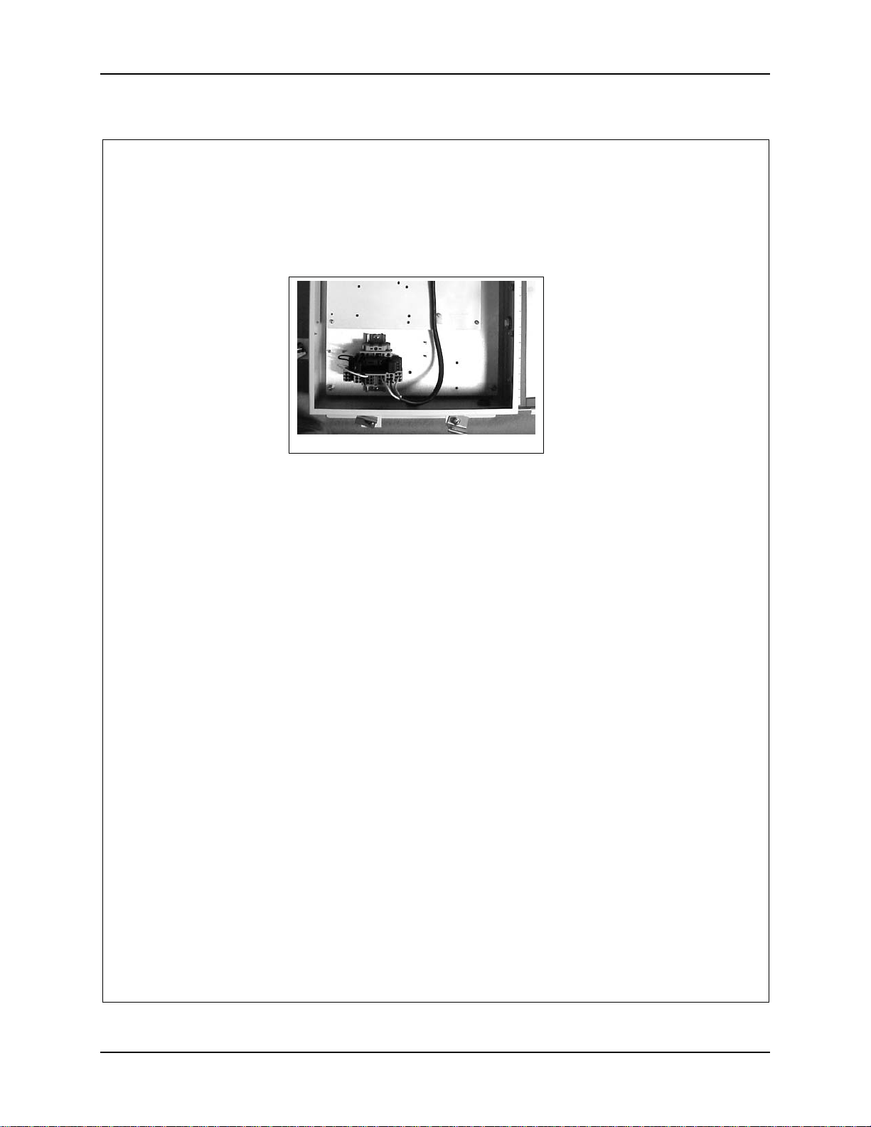
25. Plug the antenna cables into the AP.
26. Install a cable tie down on the AP mounting plate as shown in figure 12.
Figure 12
27. Secure the power cord to the tie down with an 8” nylon cable tie. Pull it tight
and trim.
28. Connect Power and Data cables per installation manual.
159084-0001 Rev. B Page 8 of 8
NEMA Type 4 Enclosure Reference Guide E-EQ-NEMARG-F
Page 51
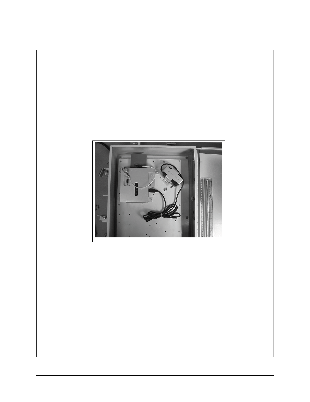
Installation Procedure, LXE Model 6543 Bridge (non-RoHS)
159085-0001
Rev. B
INSTALLATION PROCEDURE
LXE Model 6543 Bridge, Proxim MP11
NEMA 4 ENCLOSURE
159085-0001 Rev. B Page 1 of 8
E-EQ-NEMARG-F NEMA Type 4 Enclosure Reference Guide
Page 52
44 Installation Procedure, LXE Model 6543 Bridge (non-RoHS)
Qty
Qty
Qty
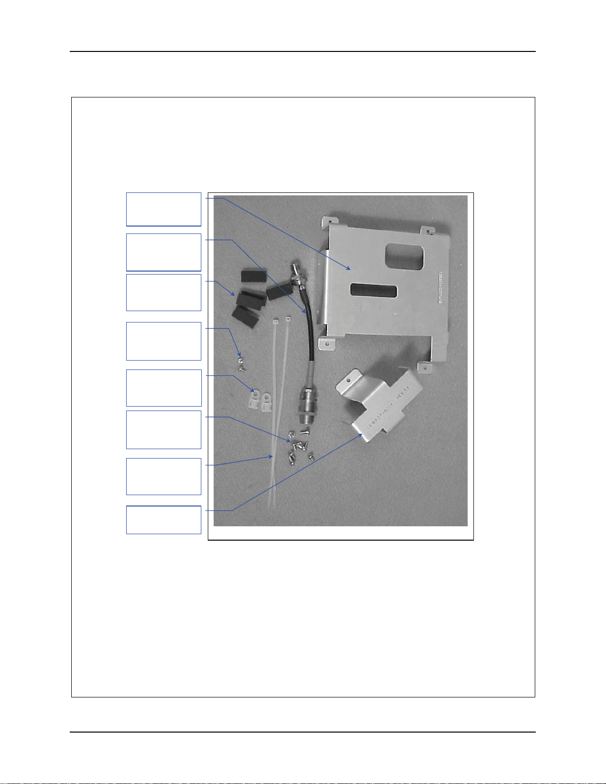
1. Remove the hardware Package from the enclosure.
2. Remove contents and verify the quantities. See figure 1.
Bracket, Qty. 1
(158934-0001)
Antenna Cable
(158887-0001)
Qty. 1
Pad, Foam
(155154-0001)
. 5
#4-40 Screw,
1/4”long. Qty 2
(137646-0404)
Nylon Tie Down
(703006-0000)
. 3
#6-32 Screw,
5/16”long. Qty 9
(137646-0606)
8” Nylon Tie
(703028-0000)
. 3
Bracket, Qty. 1
(158937-0001)
Figure 1
159085-0001 Rev. B Page 2 of 8
NEMA Type 4 Enclosure Reference Guide E-EQ-NEMARG-F
Page 53
Installation Procedure, LXE Model 6543 Bridge (non-RoHS) 45
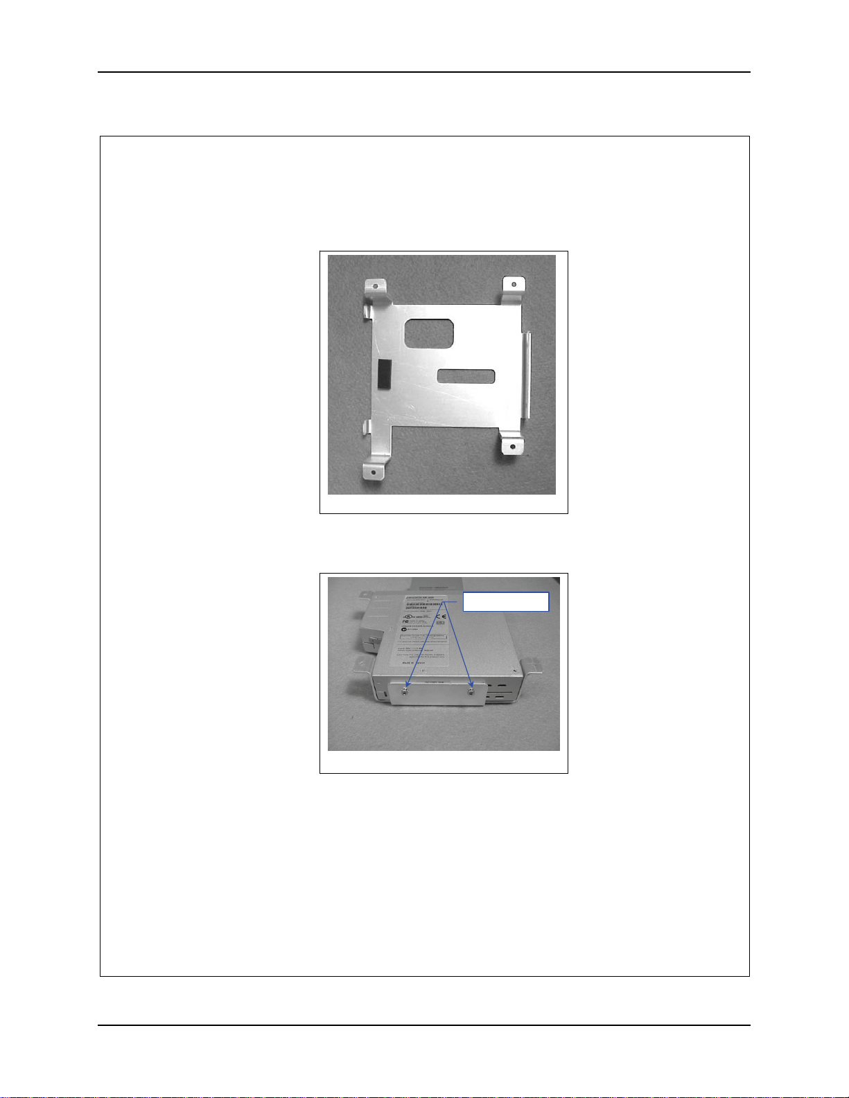
3. Prep the Bracket to accept the AP. Remove the adhesive backing and apply a
foam pad, 155154-0001 to bracket, 158941-0001 as shown in figure 2.
Figure 2
4. Insert the Bridge top first into the bracket.
5. Secure the Bridge with two (2) 4-40 screws. See figure 3.
-
Figure 3
6. Locate the Bridge, secured in the bracket, on the AP Mounting plate.
159085-0001 Rev. B Page 3 of 8
E-EQ-NEMARG-F NEMA Type 4 Enclosure Reference Guide
Page 54
46 Installation Procedure, LXE Model 6543 Bridge (non-RoHS)
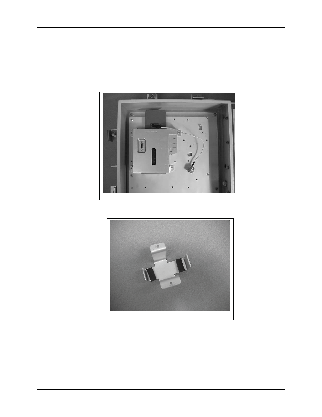
7. Secure the Bridge to the AP Mounting Plate with four (4) 6-32 screws.
Figure 4
8. Remove the adhesive backing and apply two of the foam pads to bracket,
158937-0001 as shown in figure 5.
Figure 5
159085-0001 Rev. B Page 4 of 8
NEMA Type 4 Enclosure Reference Guide E-EQ-NEMARG-F
Page 55
Installation Procedure, LXE Model 6543 Bridge (non-RoHS) 47
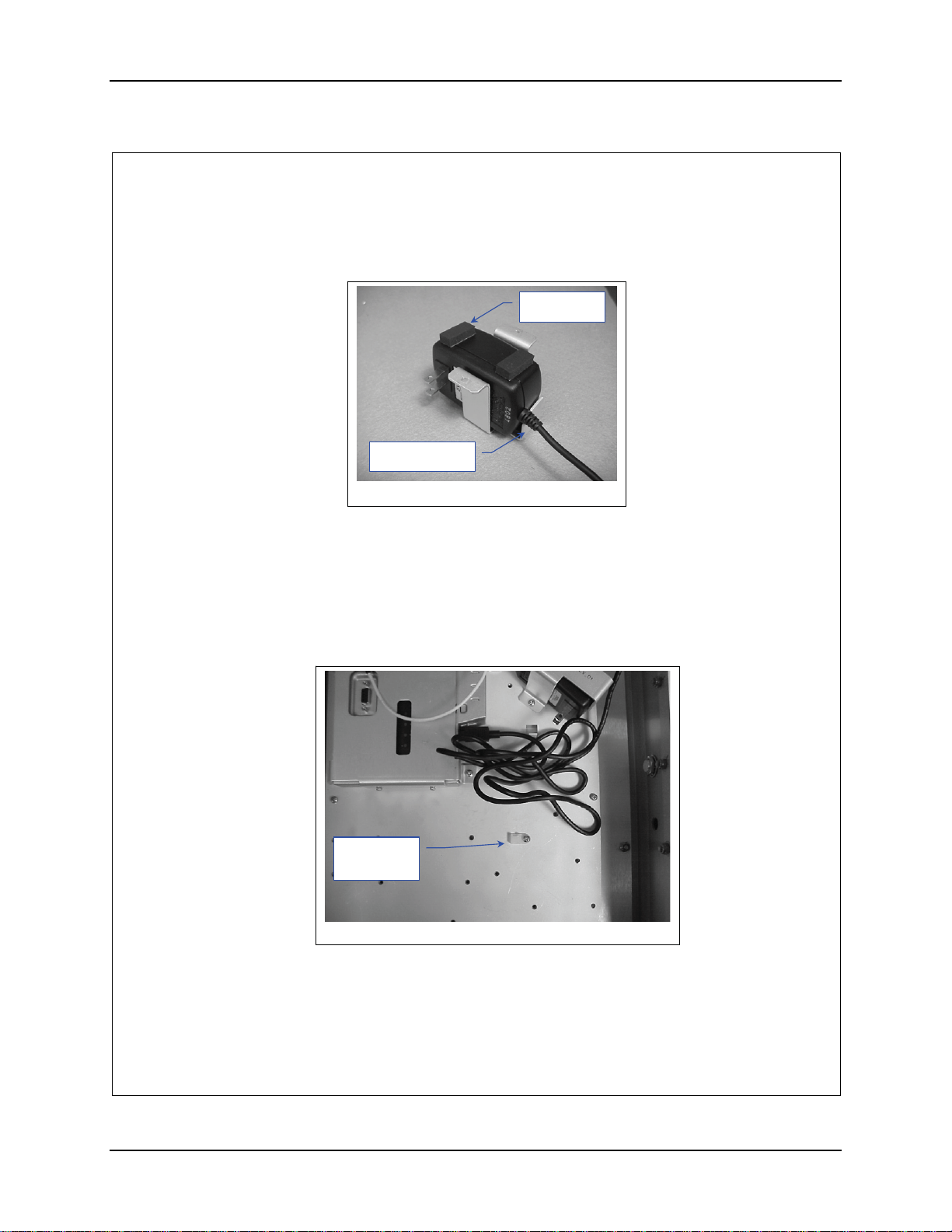
9. Position the AC power Transformer in the bracket with the output cord near
the notched tab on the bracket. See figure 6.
Foam Pads
Notched Tab
Figure 6
10. Remove the adhesive backing and apply the remaining two (2) foam pads to
the transformer, as shown in figure 6
11. Locate the transformer and bracket on the AP Mounting Plate. See figure 7.
12. Secure the bracket with two (2) 6-32 screws.
13. Install a cable tie down on the AP Mounting Plate as shown in figure 7.
Cable Tie
Down
Figure 7
14. Plug the power cord in to the Bridge.
159085-0001 Rev. B Page 5 of 8
E-EQ-NEMARG-F NEMA Type 4 Enclosure Reference Guide
Page 56
48 Installation Procedure, LXE Model 6543 Bridge (non-RoHS)
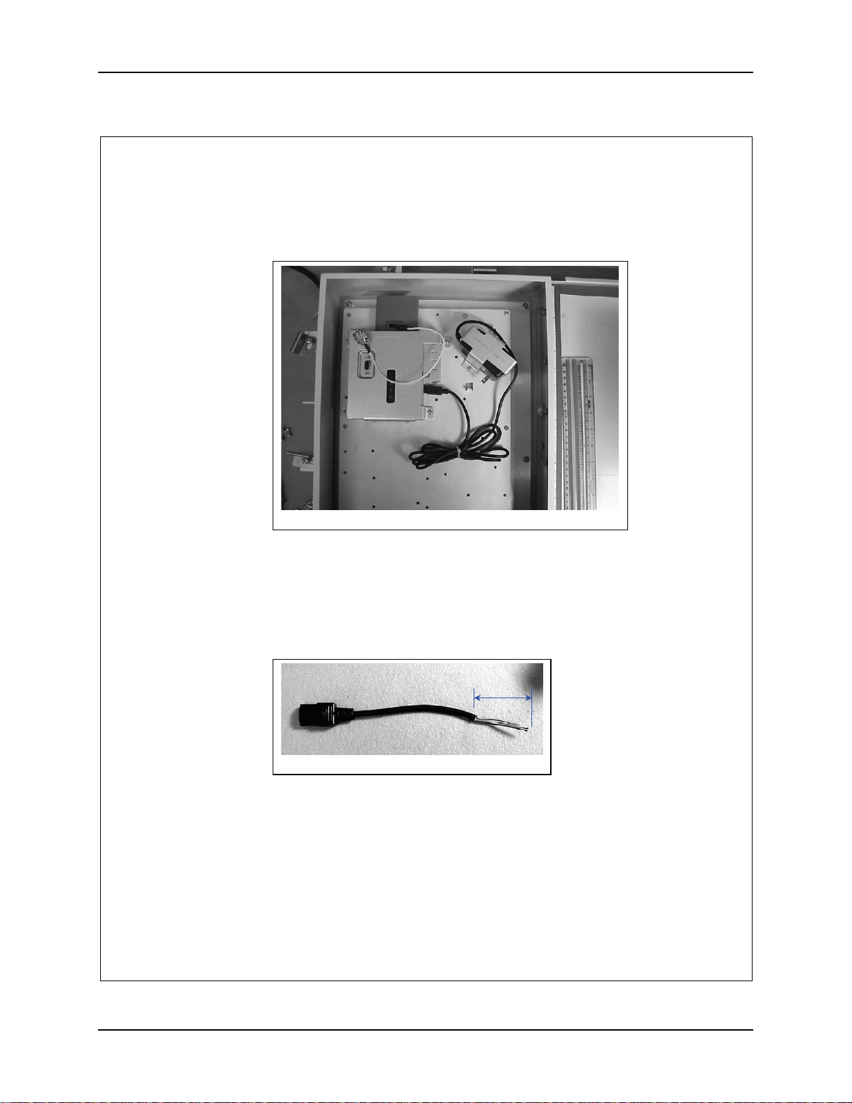
15. Bundle the loose cord up and secure it with an 8” nylon cable tie. See figure
8.
Figure 8
16. Obtain a female power cord (Supplied Locally).
17. Plug the cord into the power transformer and route it to the terminal block.
18. Cut the cord and remove at least 2” inches of the outer covering from the cut
end of the cord. See figure 9.
2”
Figure 9
19. Remove 0.4” (10 mm) of the insulation from each conductor.
159085-0001 Rev. B Page 6 of 8
NEMA Type 4 Enclosure Reference Guide E-EQ-NEMARG-F
Page 57
Installation Procedure, LXE Model 6543 Bridge (non-RoHS) 49
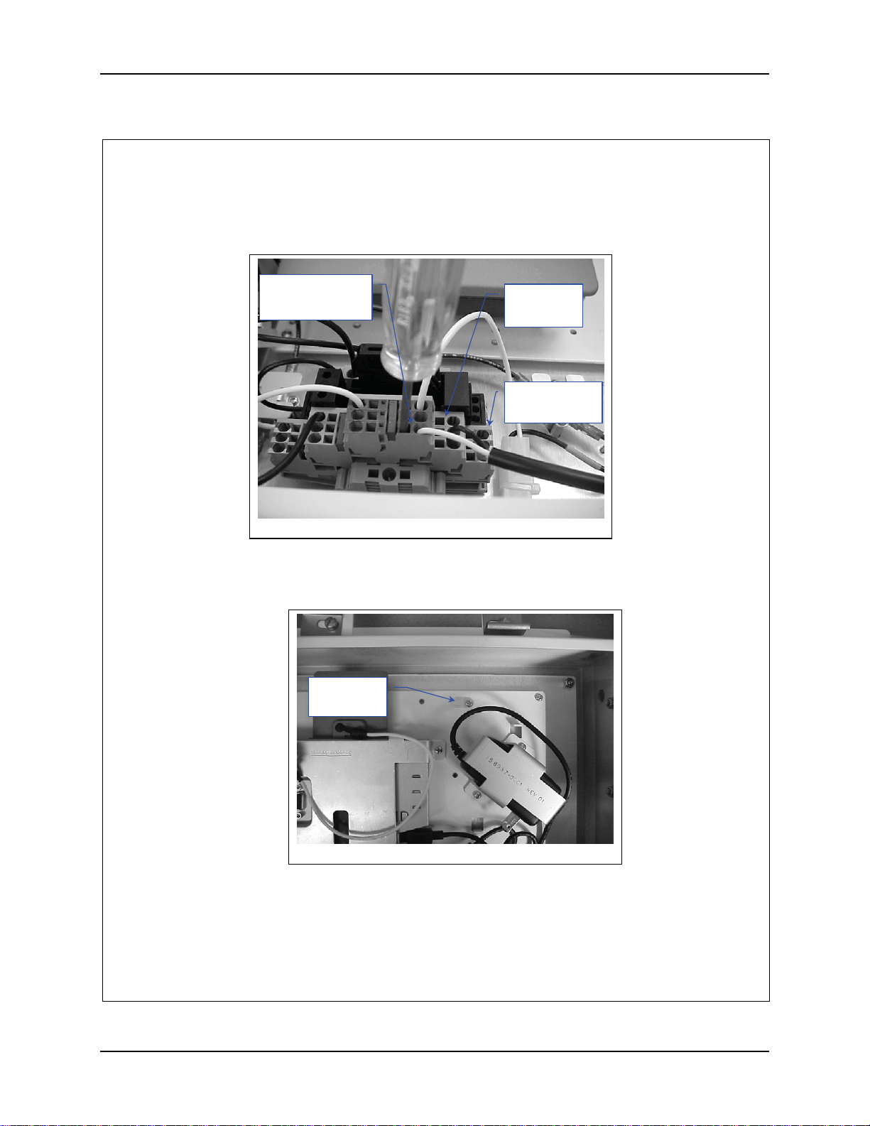
20. Insert the conductors into the terminal block. Neutral (marked blue) Live
(unmarked) Ground to Ground (marked green). See figure 10.
Neutral
Marked Blue
Figure 10
21. Remove the plug located on the hinge side of the enclosure closest to the top.
22. Install a cable tie down on the AP Mounting Plate as shown in figure 7.
Cable Tie
Down
Live
Unmarked
Ground
Marked Green
Figure 11
23. Insert the antenna cable into the hole and secure it.
159085-0001 Rev. B Page 7 of 8
E-EQ-NEMARG-F NEMA Type 4 Enclosure Reference Guide
Page 58
50 Installation Procedure, LXE Model 6543 Bridge (non-RoHS)
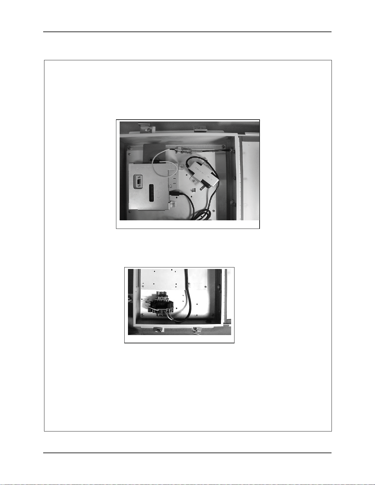
24. Connect the Bridge antenna cable to the antenna cable you just installed.
25. Route the antenna cables as shown in figure 10.
Figure 12
26. Secure the Antenna cables with an 8” nylon cable tie at the junction of the two
cables. Pull the cable tie tight and trim.
27. Install a cable tie down on the AP mounting plate as shown in figure 13.
Figure 13
28. Secure the power cord to the tie down with an 8” nylon cable tie. Pull it tight
and trim.
29. Connect Power cable per installation manual.
159085-0001 Rev. B Page 8 of 8
NEMA Type 4 Enclosure Reference Guide E-EQ-NEMARG-F
Page 59
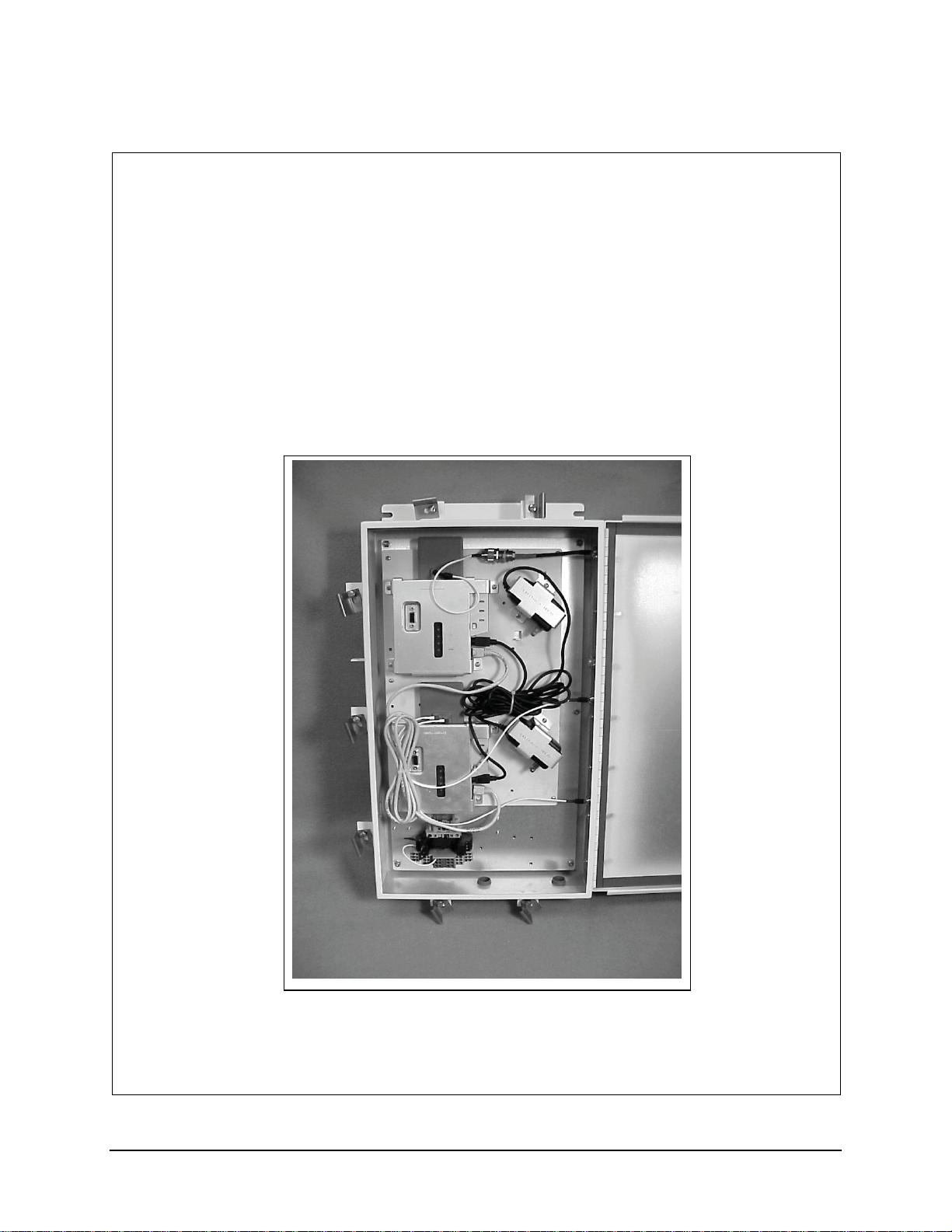
Installation Procedure, LXE Models 6453 Bridge & 6540 AP (non-RoHS)
159086-0001
Rev. B
INSTALLATION PROCEDURE
LXE Model 6543 Bridge, Proxim MP11
&
LXE Model 6540 AP, Proxim AP600
NEMA 4 ENCLOSURE
159086-0001 Rev. B Page 1 of 10
E-EQ-NEMARG-F NEMA Type 4 Enclosure Reference Guide
Page 60
52 Installation Procedure, LXE Models 6453 Bridge & 6540 AP (non-RoHS)
Qty
Qty
Qty
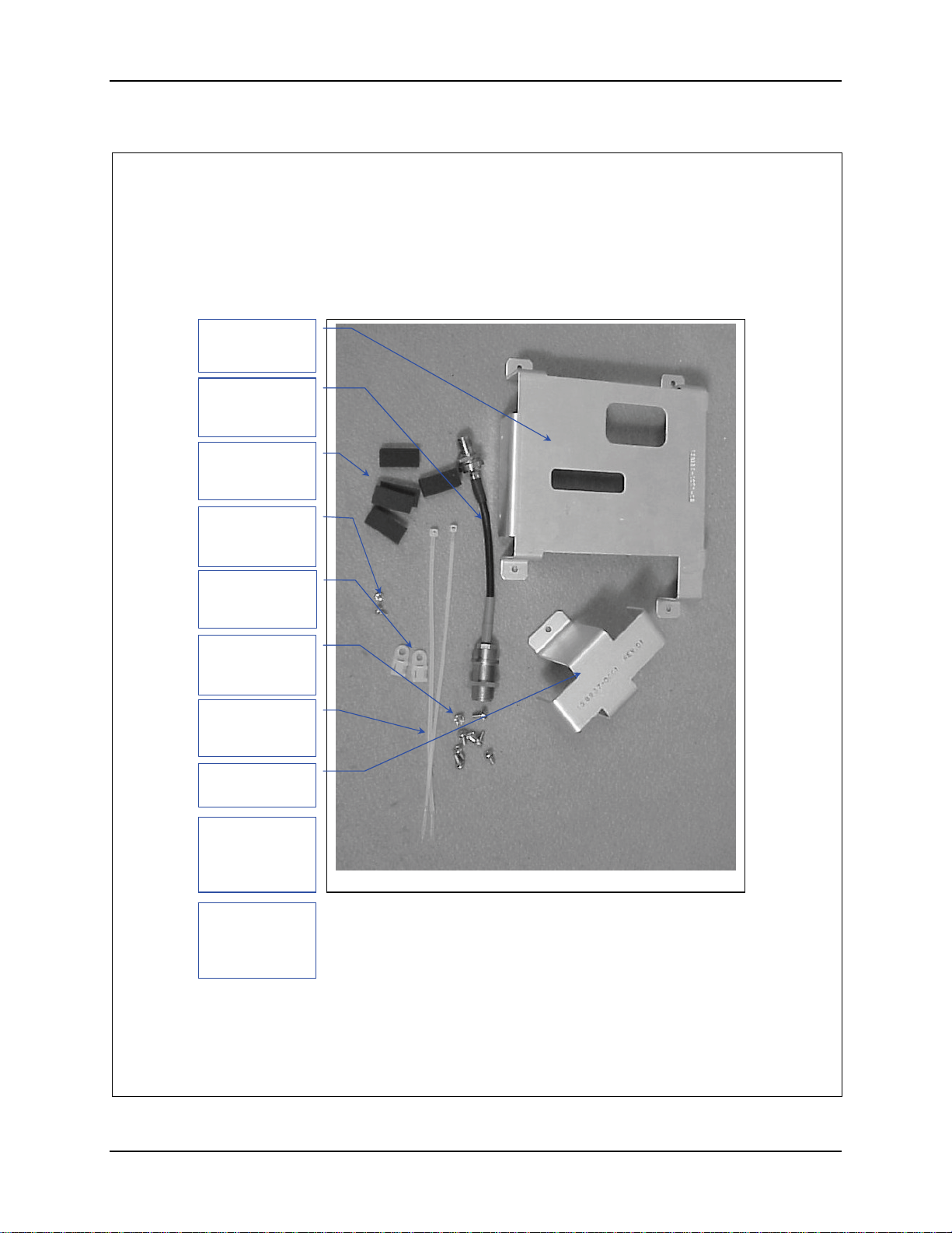
1. Remove the hardware Package from the enclosure.
2. Remove contents and verify the quantities. See figure 1.
Bracket, Qty. 2
(158934-0001)
Antenna Cable
(158887-0001)
Qty. 1
Pad, Foam
(155154-0001)
. 10
#4-40 Screw,
1/4”long. Qty 4
(137646-0404)
Nylon Tie Down
(703006-0000)
. 2
#6-32 Screw,
5/16”long. Qty 14
(137646-0606)
8” Nylon Tie
(703028-0000)
. 3
Bracket, Qty. 2
(158937-0001)
Antenna Cable
(159078-0001)
Qty 2
Not Shown
Hardware Package
Figure 1
Crossover Cable
(425042-0836)
Qty 1
Not Shown
159086-0001 Rev. B Page 2 of 10
NEMA Type 4 Enclosure Reference Guide E-EQ-NEMARG-F
Page 61
Installation Procedure, LXE Models 6453 Bridge & 6540 AP (non-RoHS) 53
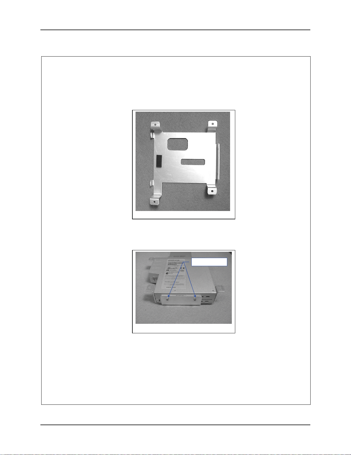
3. Prep the Brackets to accept the AP and the Bridge. Remove the adhesive
backing and apply a foam pad, 155154-0001 to each bracket, 158941-0001 as
shown in figure 2.
Figure 2
4. Insert the Bridge top first into the bracket. Repeat for the AP.
5. Secure the Bridge with two (2) 4-40 screws. See figure 3. Repeat for The
AP.
-
Figure 3
6. Locate the Bridge, secured in the bracket, on the AP Mounting plate.
159086-0001 Rev. B Page 3 of 10
E-EQ-NEMARG-F NEMA Type 4 Enclosure Reference Guide
Page 62
54 Installation Procedure, LXE Models 6453 Bridge & 6540 AP (non-RoHS)
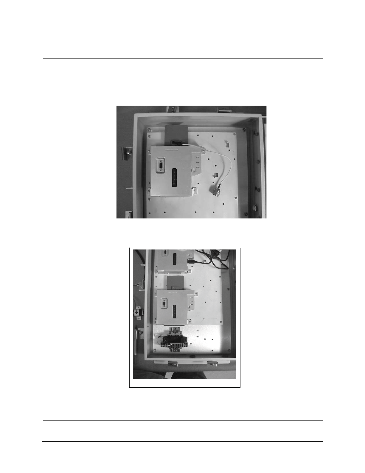
7. Secure the Bridge to the AP Mounting Plate with four (4) 6-32 screws.
Figure 4
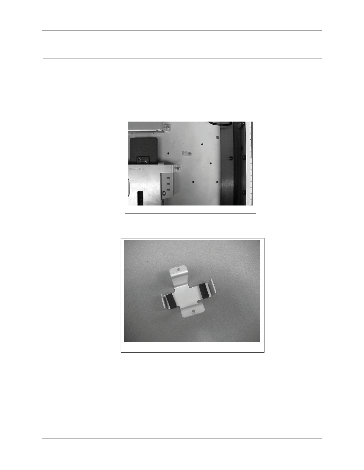
8. Locate the AP, secured in the bracket, on the AP Mounting plate below the
Bridge. See figure 4a.
Figure 4a
159086-0001 Rev. B Page 4 of 10
NEMA Type 4 Enclosure Reference Guide E-EQ-NEMARG-F
Page 63
Installation Procedure, LXE Models 6453 Bridge & 6540 AP (non-RoHS) 55
9. Secure the Bridge to the AP Mounting Plate with four (4) 6-32 screws.
10. Install a cable tie down on the AP Mounting Plate as shown in figure 5.
Figure 5
11. Remove the adhesive backing and apply two of the foam pads to each bracket,
158937-0001 as shown in figure 6.
Figure 6
159086-0001 Rev. B Page 5 of 10
E-EQ-NEMARG-F NEMA Type 4 Enclosure Reference Guide
Page 64
56 Installation Procedure, LXE Models 6453 Bridge & 6540 AP (non-RoHS)
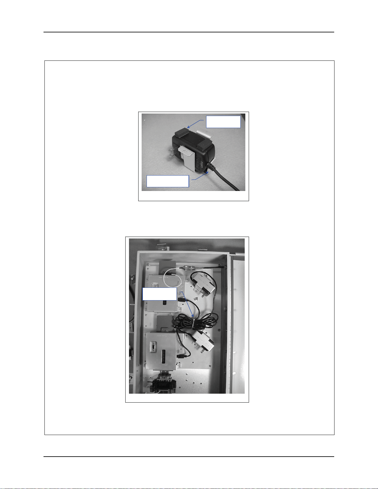
12. Position the AC power Transformer in the bracket with the output cord near
the notched tab on the bracket. See figure 7.
Foam Pads
Notched Tab
Figure 7
13. Remove the adhesive backing and apply two (2) foam pads to each
transformer, as shown in figure 7.
14. Locate the transformers in the bracket on the AP Mounting Plate. See figure
8.
Cable Tie
Figure 8
159086-0001 Rev. B Page 6 of 10
NEMA Type 4 Enclosure Reference Guide E-EQ-NEMARG-F
Page 65
Installation Procedure, LXE Models 6453 Bridge & 6540 AP (non-RoHS) 57
15. Secure the bracket with two (2) 6-32 screws for each transformer.
16. Plug the power cord from the upper transformer into the Bridge.
17. Plug the power cord from the lower transformer into the AP.
18. Bundle the loose cords up and secure them with an 8” nylon cable tie. See
figure 8.
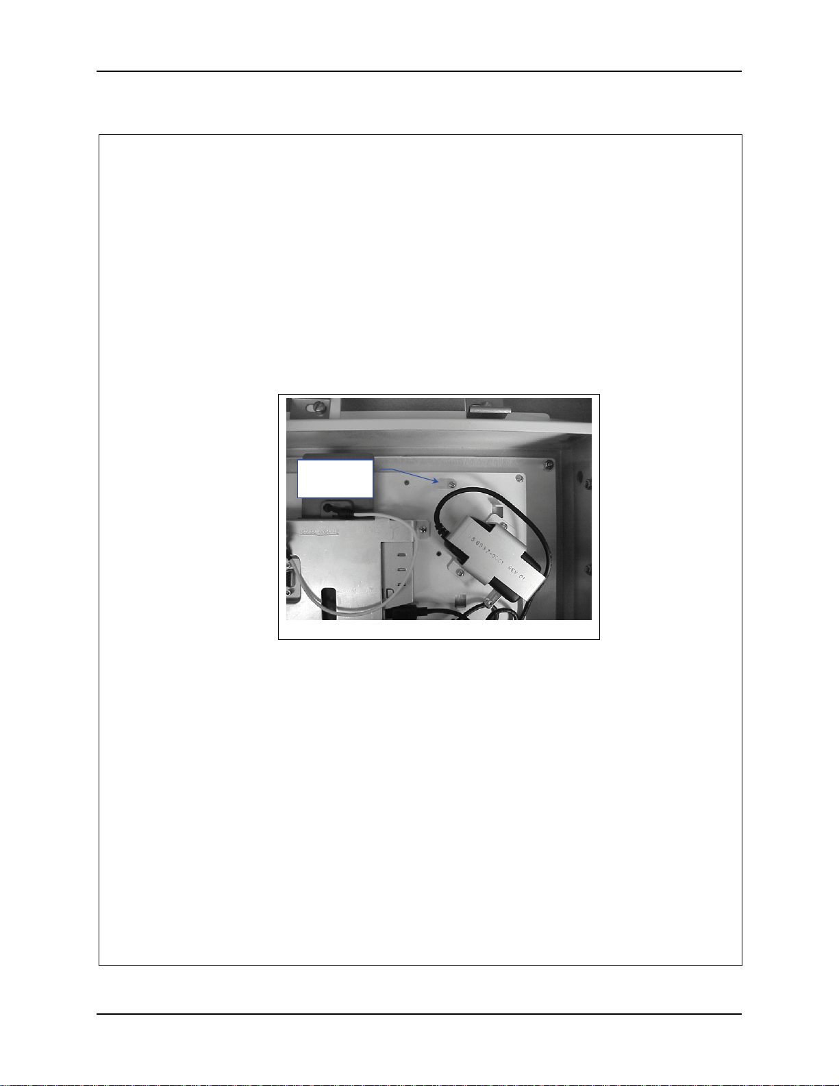
19. Remove the plug located on the hinge side of the enclosure closest to the top.
20. Install a cable tie down on the AP Mounting Plate as shown in figure 9.
Cable Tie
Down
Figure 9
21. Insert the antenna cable, 158887-0001, into the hole and secure it.
22. Connect the Bridge antenna cable to the antenna cable you just installed.
159086-0001 Rev. B Page 7 of 10
E-EQ-NEMARG-F NEMA Type 4 Enclosure Reference Guide
Page 66
58 Installation Procedure, LXE Models 6453 Bridge & 6540 AP (non-RoHS)
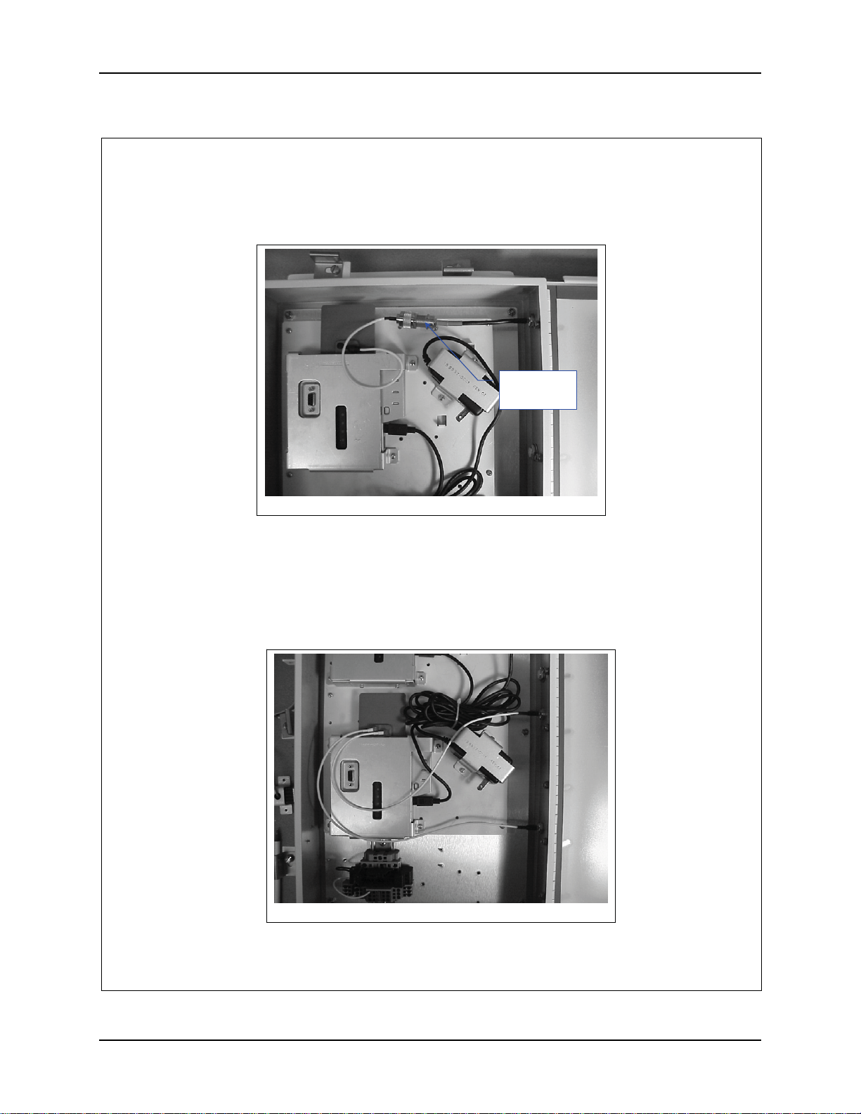
23. Route the antenna cables as shown in figure 10.
Cable Tie
here.
Figure 10
24. Secure the Antenna cables with an 8” nylon cable tie at the junction of the two
cables. See figure 10. Pull the cable tie tight and trim.
25. Remove the two (2) plugs located on the hinge side of the enclosure closest to
the bottom.
26. Route the antenna cables as shown in figure 11.
Figure 11
159086-0001 Rev. B Page 8 of 10
NEMA Type 4 Enclosure Reference Guide E-EQ-NEMARG-F
Page 67
Installation Procedure, LXE Models 6453 Bridge & 6540 AP (non-RoHS) 59
27. Insert the antenna cable connectors in the holes and secure them.
28. Plug the antenna cables into the AP.
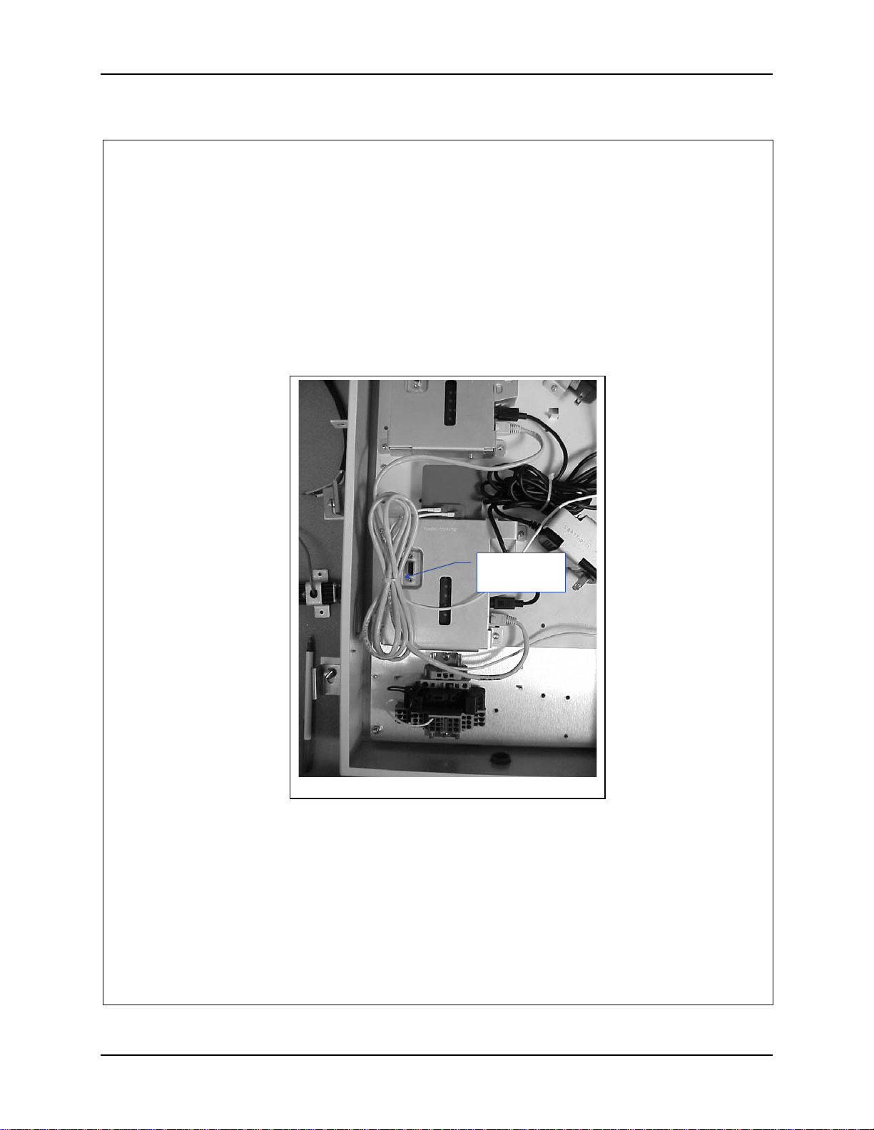
29. Route and connect the Crossover cable between the AP and the Bridge.
30. Secure the crossover cable and the AP antenna cables to the AP bracket. See
figure 12. Loop the cable tie between the bracket and the AP. Pull it tight and
trim.
Cable tie
goes here.
Figure 12
31. Obtain two (2) female power cords (Supplied Locally).
32. Plug a cord into each power transformer and route it to the terminal block.
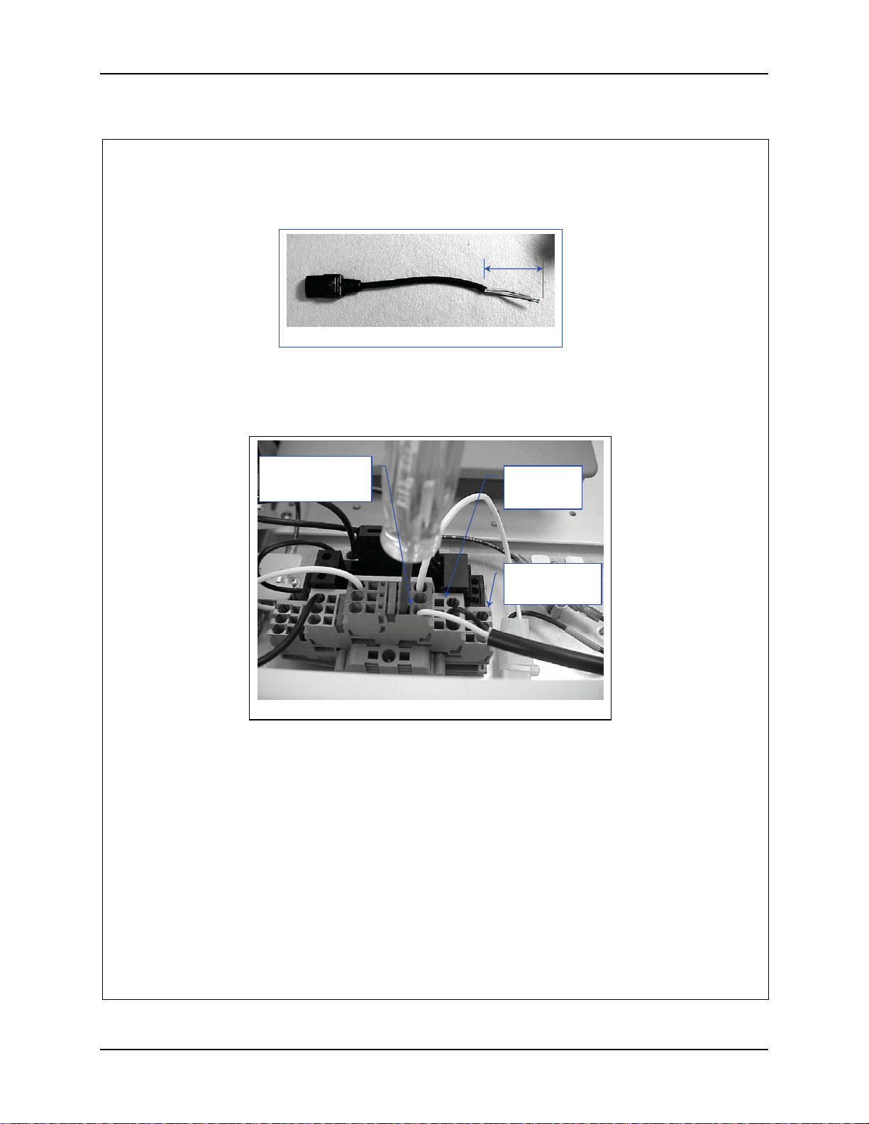
33. Cut the cords and remove at least 2” inches of the outer covering from the cut
end of the cord. See figure 13.
159086-0001 Rev. B Page 9 of 10
E-EQ-NEMARG-F NEMA Type 4 Enclosure Reference Guide
Page 68
60 Installation Procedure, LXE Models 6453 Bridge & 6540 AP (non-RoHS)
2”
Figure 13
34. Remove 0.4” (10 mm) of the insulation from each conductor.
35. Insert the conductors into the terminal block. Neutral (marked blue) Live
(unmarked) Ground to Ground (marked green). See figure 14.
Neutral
Marked Blue
Figure 14
36. Connect Power per installation manual.
Live
Unmarked
Ground
Marked Green
159086-0001 Rev. B Page 10 of 10
NEMA Type 4 Enclosure Reference Guide E-EQ-NEMARG-F
Page 69
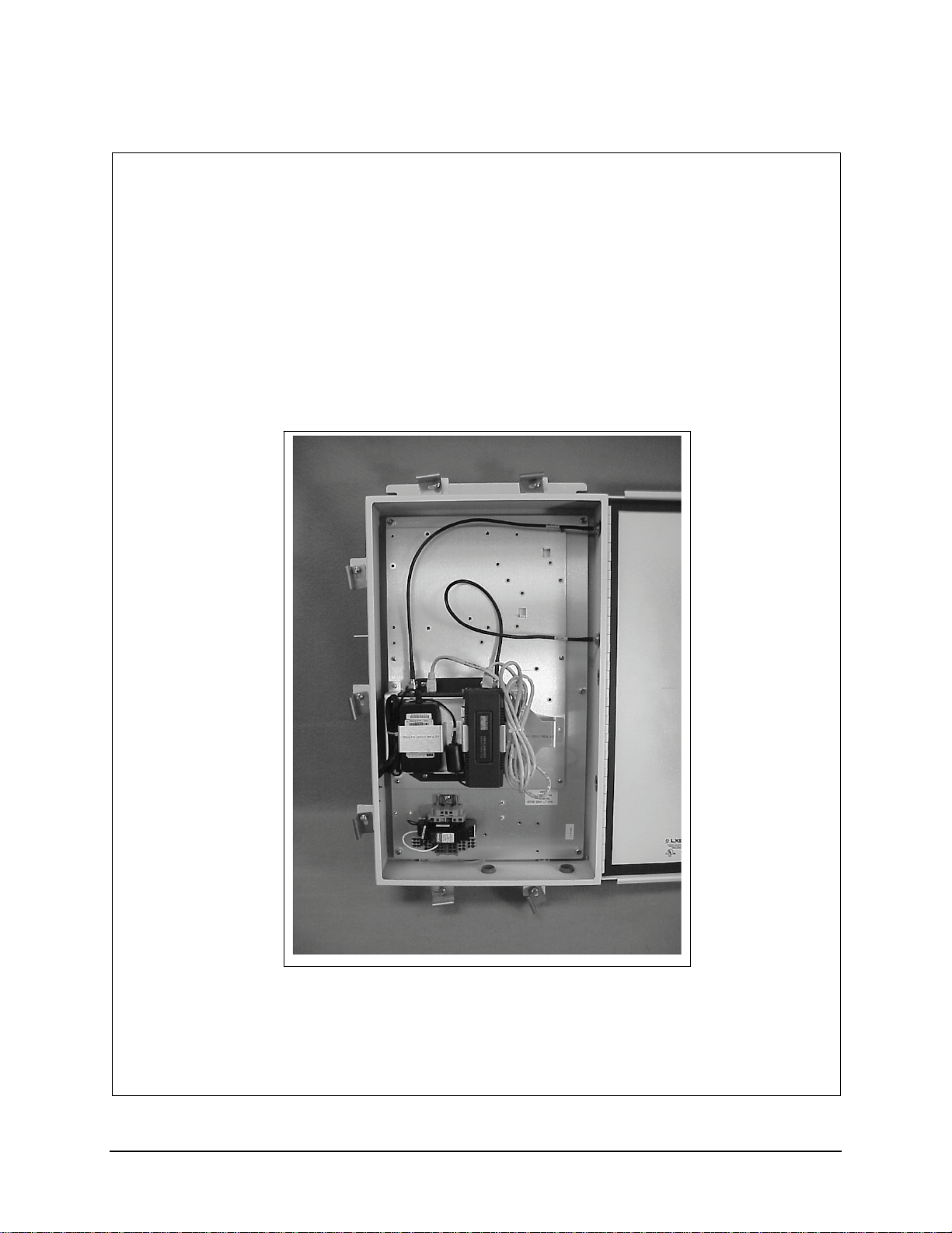
Installation Procedure, LXE Model 6720 AP (non-RoHS)
159087-0001
Rev. C
INSTALLATION PROCEDURE
LXE Model 6720 AP, CISCO 350AP
NEMA 4 ENCLOSURE
159087-0001 Rev. C Page 1 of 8
E-EQ-NEMARG-F NEMA Type 4 Enclosure Reference Guide
Page 70
62 Installation Procedure, LXE Model 6720 AP (non-RoHS)
Qty
Qty
Qty
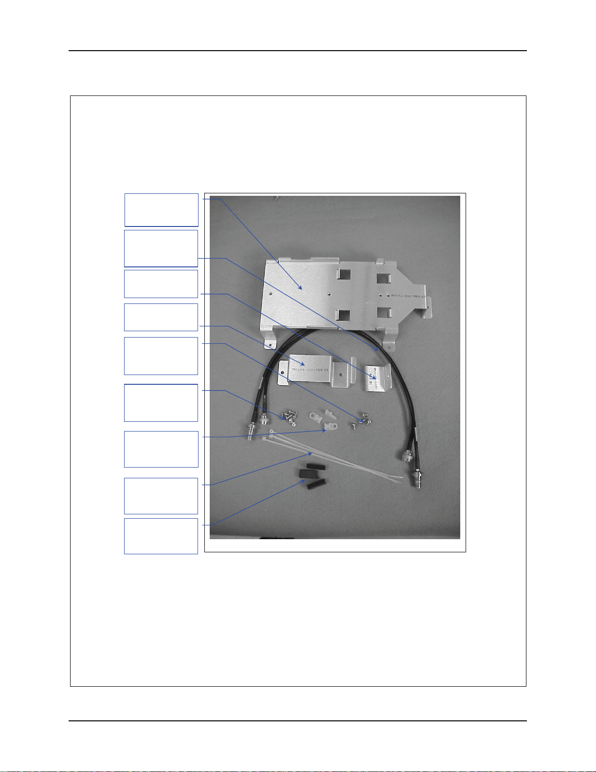
1. Remove the hardware package from the enclosure.
2. Remove contents and verify the quantities. See figure 1.
Bracket, Qty. 1
(160042-0001)
Antenna Cable
(158877-0001)
Qty. 2
Bracket, Qty. 1
(160046-0001)
Bracket, Qty. 1
(160043-0001)
#8-32 Screw,
1/4”long. Qty 4
(137646-0804)
#6-32 Screw,
5/16”long. Qty 8
(137646-0606)
Nylon Tie Down
(703006-0000)
. 3
8” Nylon Tie
(703028-0000)
. 3
Pad, Foam
(155154-0001)
. 3
Hardware Package
Figure 1
159087-0001 Rev. C Page 2 of 8
NEMA Type 4 Enclosure Reference Guide E-EQ-NEMARG-F
Page 71
Installation Procedure, LXE Model 6720 AP (non-RoHS) 63
Qty
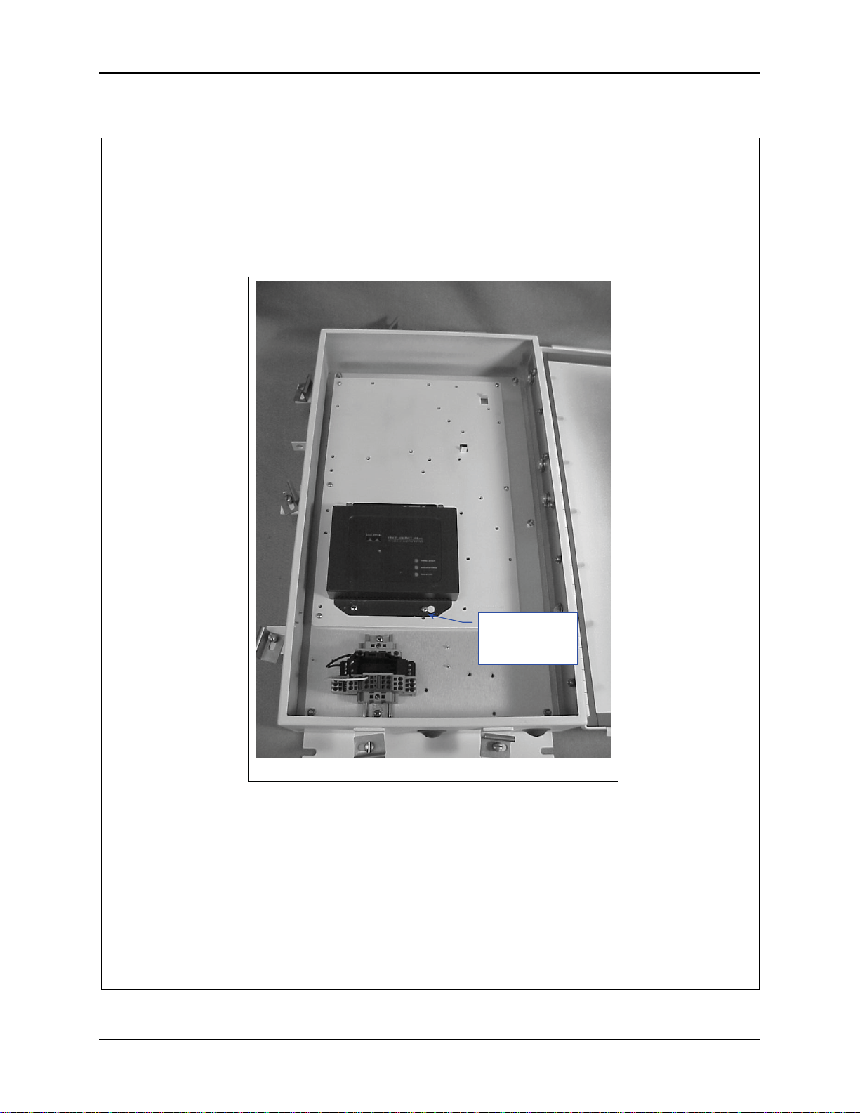
3. Locate the AP on the AP Mounting Plate. See figure 2.
4. Secure the AP to the AP Mounting Plate with four (4) 8-32 screws. See figure
2.
#8-32 Screw
¼” long.
. 4
Figure 2
5. If the AP is going to be powered over Ethernet, skip to step 23.
159087-0001 Rev. C Page 3 of 8
E-EQ-NEMARG-F NEMA Type 4 Enclosure Reference Guide
Page 72
64 Installation Procedure, LXE Model 6720 AP (non-RoHS)
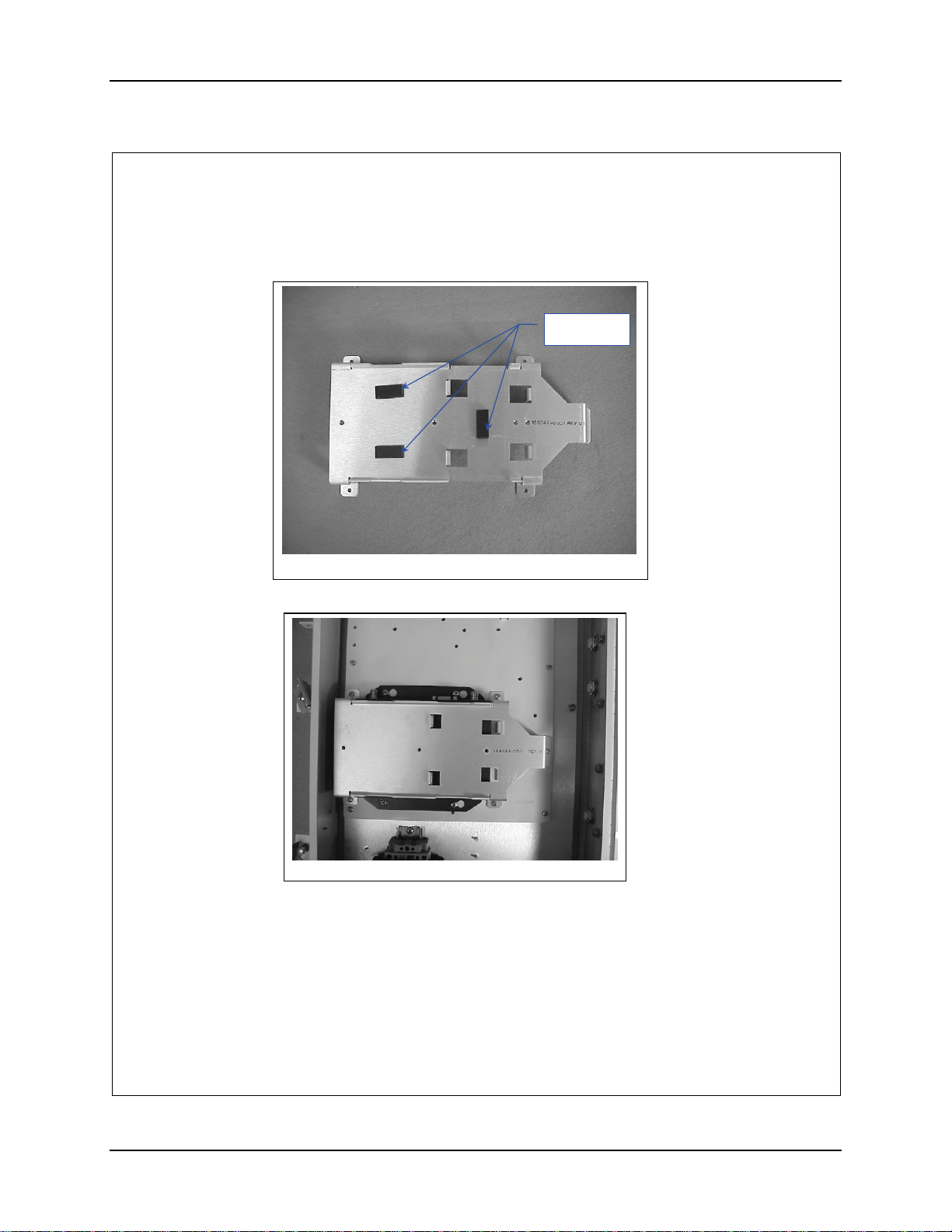
6. Remove the adhesive backing and apply the three (3) foam pads to the bracket
as shown in figure 3.
Foam pads
Figure 3
7. Position bracket 160042-0001 over the AP. See figure 4.
Figure 4
8. Secure the bracket with five (5) 6-32 screws 5/16” long.
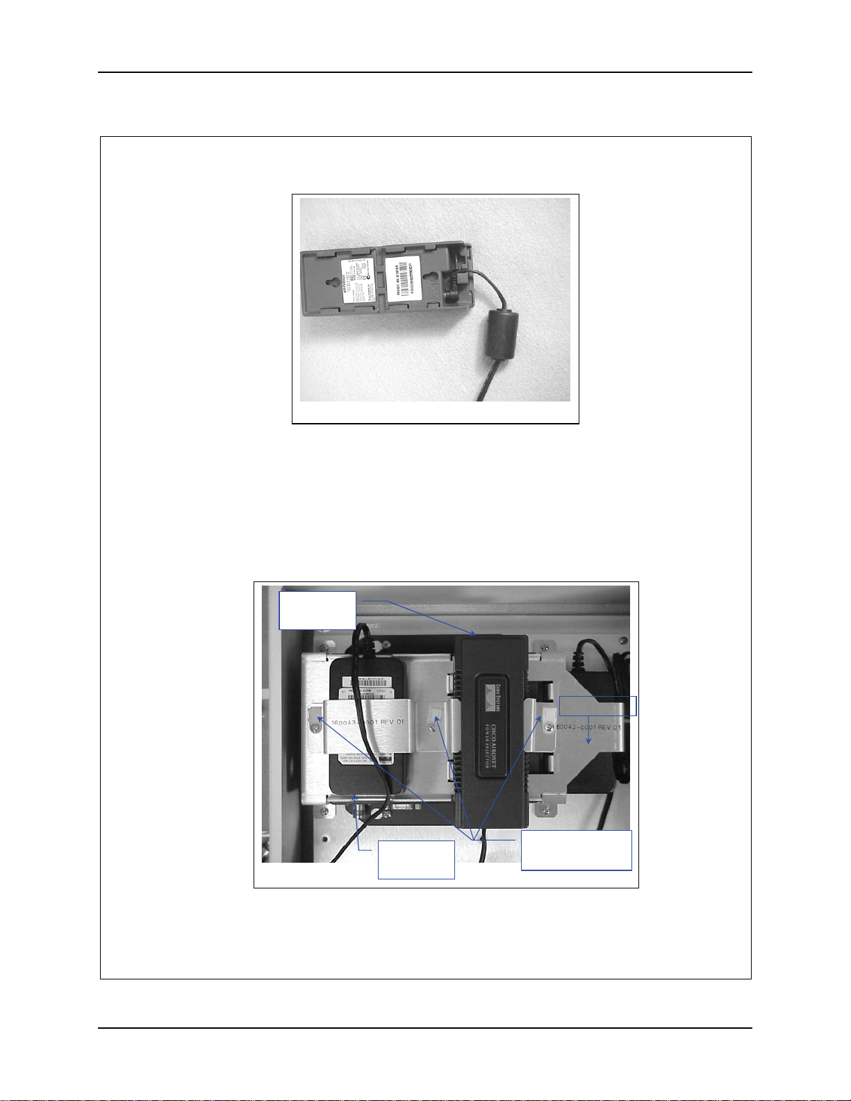
9. Plug the output power cord from the Power Brick into the Power Injector.
Route cable as shown in figure 5.
159087-0001 Rev. C Page 4 of 8
NEMA Type 4 Enclosure Reference Guide E-EQ-NEMARG-F
Page 73
Installation Procedure, LXE Model 6720 AP (non-RoHS) 65
Figure 5
10. Position the AC Power Brick over the Foam Pads with the label side (bottom)
up and the AC input pointing towards the bottom of the box. See figure 6.
11. Position the Power Injector over the Foam Pad on bracket 160042-0001 up
against the locating tabs with the RJ45 jacks pointed towards the top of the
box. See Figure 6.
12. Place brackets 160043-0001 and 160046-0001 over the Power Brick and
Injector. See figure 6.
Network
RJ45 Conn.
Cable Tie Down
Installed Here
Figure 6
AC power
connector
159087-0001 Rev. C Page 5 of 8
E-EQ-NEMARG-F NEMA Type 4 Enclosure Reference Guide
Page 74
66 Installation Procedure, LXE Model 6720 AP (non-RoHS)
13. Place a nylon tie down over the screw holes of the brackets. See figure 6.
14. Secure the tie downs and the bracket with three (3) 6-32x 5/16” long screws.
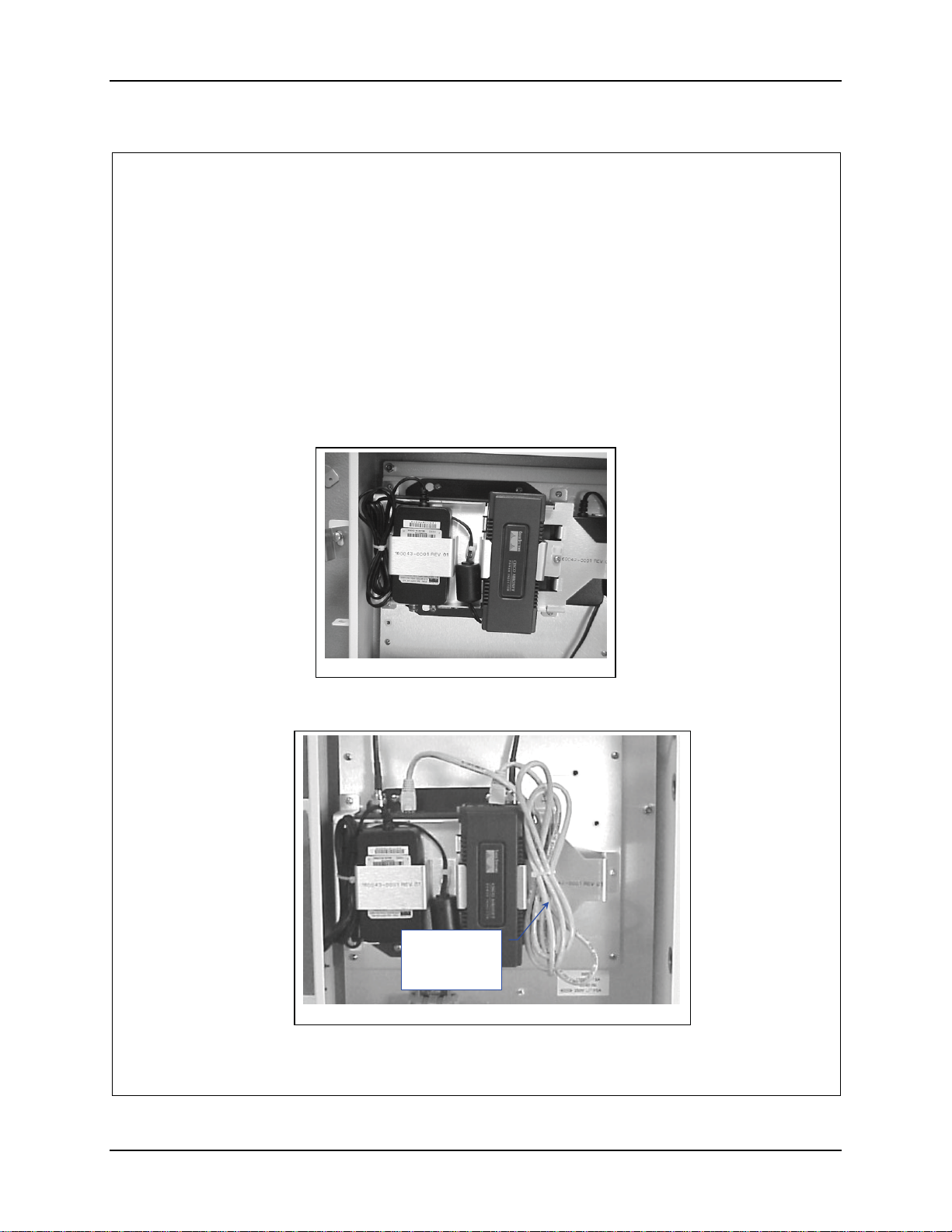
15. Route the power cord from the Power Injector between the Power Brick and
the Power Injector and secure the ferrite with a nylon cable tie. See Figure 7.
16. Route the power cord around the top of the Power Brick.
17. Bundle it and secure it with a nylon cable tie on the LEFT side of the Power
Brick. See figure 7.
Figure 7
18. Connect the Ethernet Cable (supplied with the AP) to the Power Injector and
the AP. See figure 8.
Data cable
Supplied with
AP
Figure 8
159087-0001 Rev. C Page 6 of 8
NEMA Type 4 Enclosure Reference Guide E-EQ-NEMARG-F
Page 75
Installation Procedure, LXE Model 6720 AP (non-RoHS) 67
19. Bundle it and secure it with a nylon cable tie on the RIGHT side of the Power
Injector. See figure 8.
20. Measure 10” from the universal plug end of the AC power cord (supplied with
the AP) and cut. Discard the remainder of the cord.
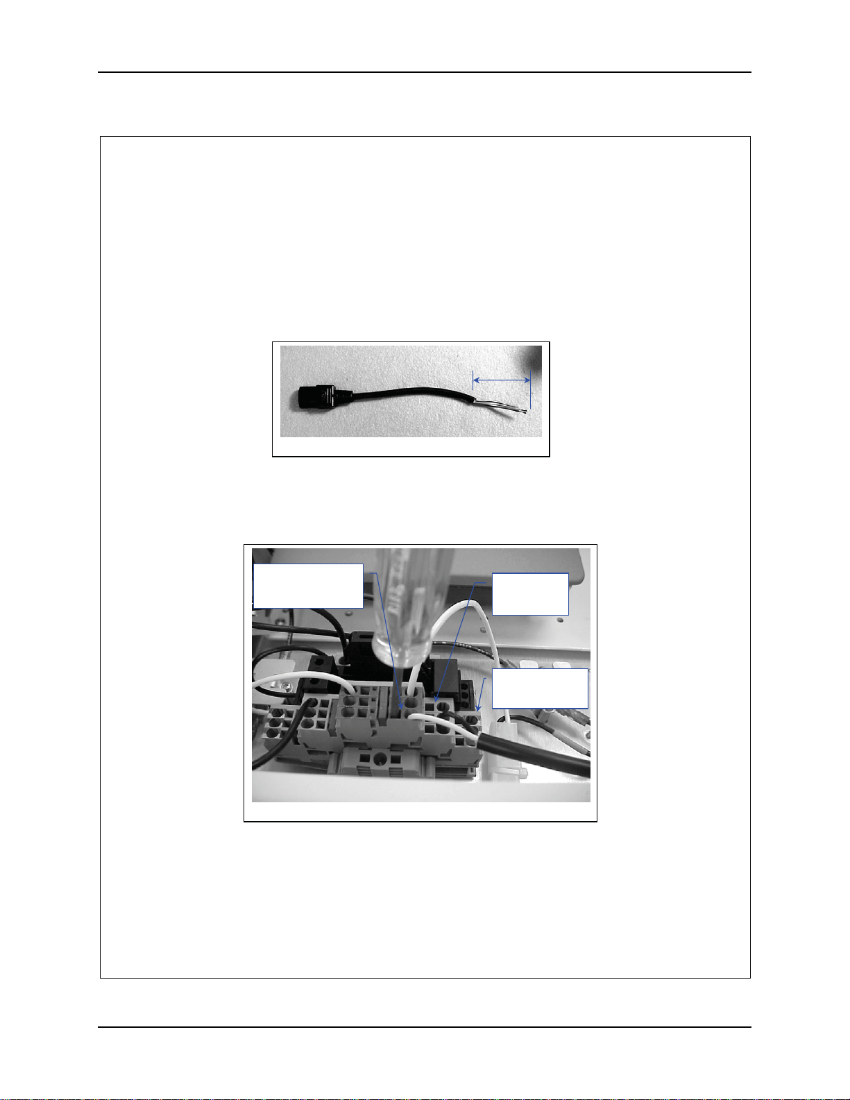
21. Remove at least 2” inches of the outer covering from the cut end of the cord.
See figure 9.
2”
Figure 9
22. Remove 0.4” (10 mm) of the insulation from each conductor.
23. Insert the conductors into the terminal block. Neutral (marked blue), Live
(unmarked), Ground to Ground (marked green). See figure 10.
Neutral
Marked Blue
Figure 10
24. Plug the other end of the cable into the power brick.
25. Connect the Antenna Cables to the AP.
Live
Unmarked
Ground
Marked Green
159087-0001 Rev. C Page 7 of 8
E-EQ-NEMARG-F NEMA Type 4 Enclosure Reference Guide
Page 76
68 Installation Procedure, LXE Model 6720 AP (non-RoHS)
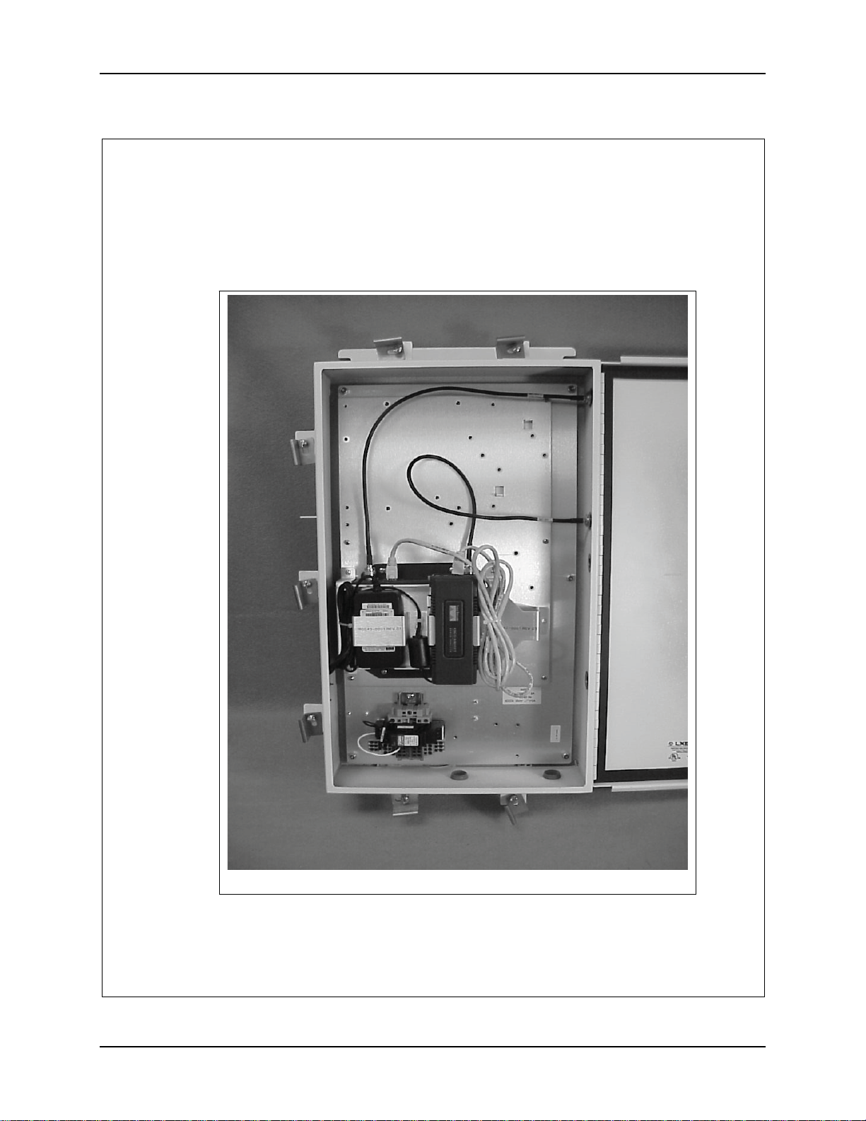
26. Remove the two (2) plugs located on the hinge side of the enclosure closest to
the top.
27. Route the Antenna Cables as shown in figure 11.
Figure 11
28. Insert the Antenna Cable connectors in the holes and secure them.
159087-0001 Rev. C Page 8 of 8
NEMA Type 4 Enclosure Reference Guide E-EQ-NEMARG-F
Page 77
Installation Procedure, LXE Model 6730 AP (non-RoHS)
159088-0001
Rev. C
INSTALLATION PROCEDURE
LXE Model 6730 AP, CISCO 1200AP
NEMA 4 ENCLOSURE
159088-0001 Rev. C Page 1 of 14
E-EQ-NEMARG-F NEMA Type 4 Enclosure Reference Guide
Page 78
70 Installation Procedure, LXE Model 6730 AP (non-RoHS)
Qty
Qty
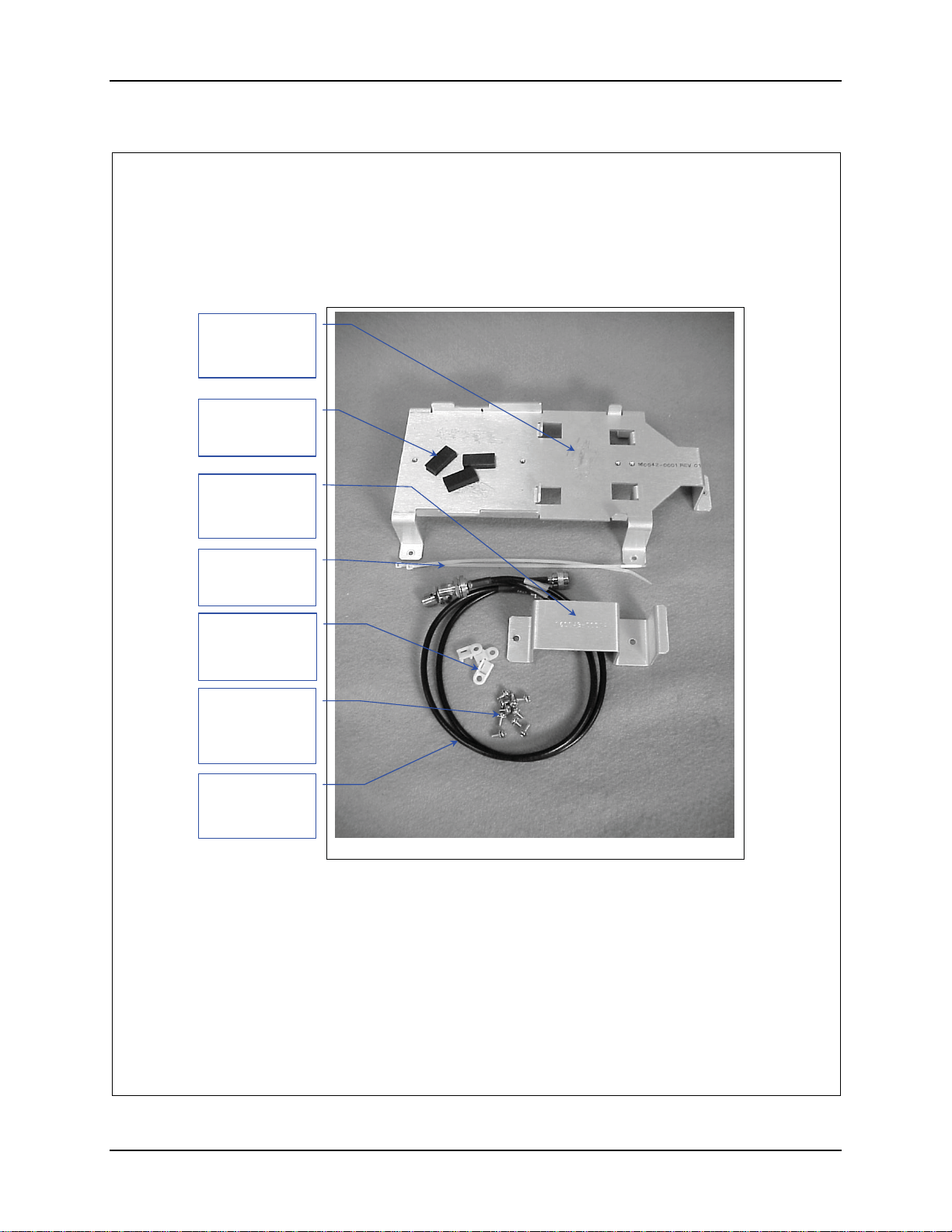
1. Remove the hardware Package from the enclosure.
2. Remove contents and verify the quantities. See figure 1.
Bracket
(160042-0001)
Qty. 1
Pad, Foam
(155154-0001)
. 3
Bracket
(160043-0001)
Qty. 1
Hardware Package
8” Nylon Tie
(703028-0000)
. 4
Nylon Tie Down
(703006-0000)
Qty. 3
#6-32 Screw,
5/16” long.
Qty. 10
(137646-0605)
Antenna Cable
(158887-0001)
Qty. 2
Figure 1
159088-0001 Rev. C Page 2 of 14
NEMA Type 4 Enclosure Reference Guide E-EQ-NEMARG-F
Page 79
Installation Procedure, LXE Model 6730 AP (non-RoHS) 71
Qty
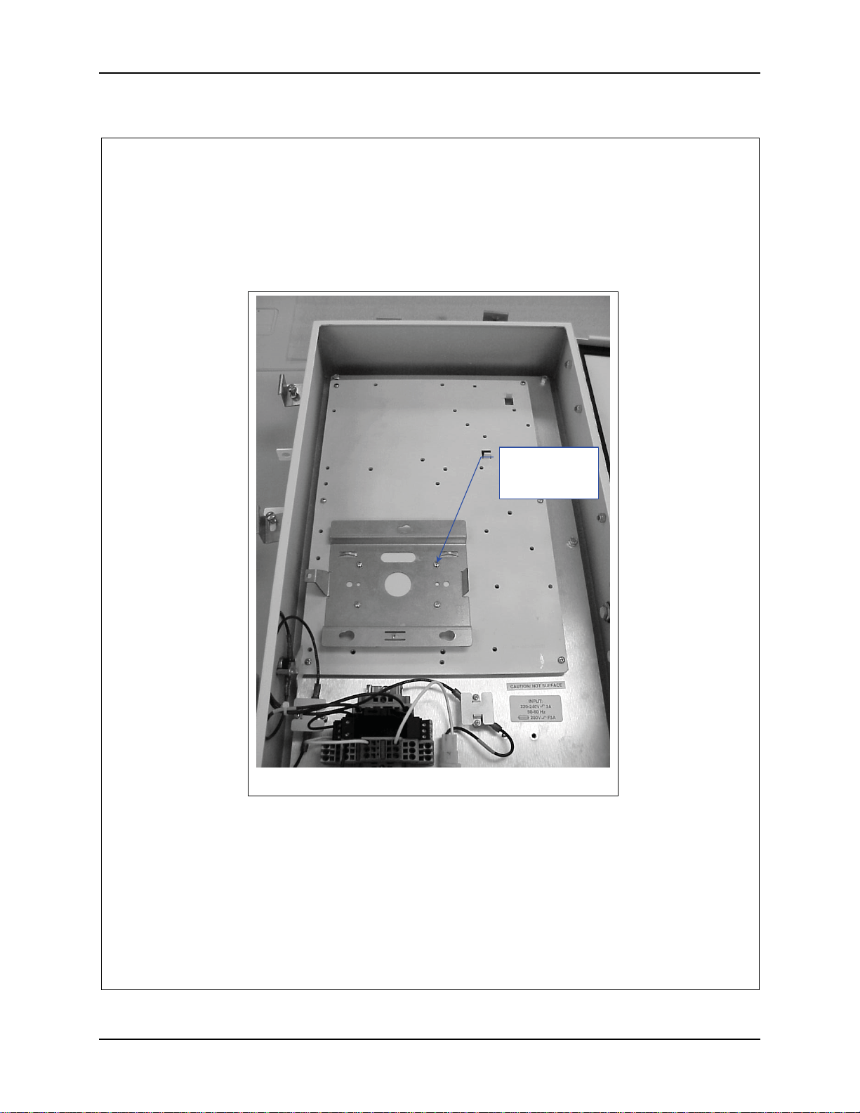
3. Install the AP Mounting Bracket (Supplied with the AP). See figure 2.
4. Secure the plate with 4 screws. See figure 2.
#6-32 Screw,
5/16” long.
. 4
Figure 2
159088-0001 Rev. C Page 3 of 14
E-EQ-NEMARG-F NEMA Type 4 Enclosure Reference Guide
Page 80
72 Installation Procedure, LXE Model 6730 AP (non-RoHS)
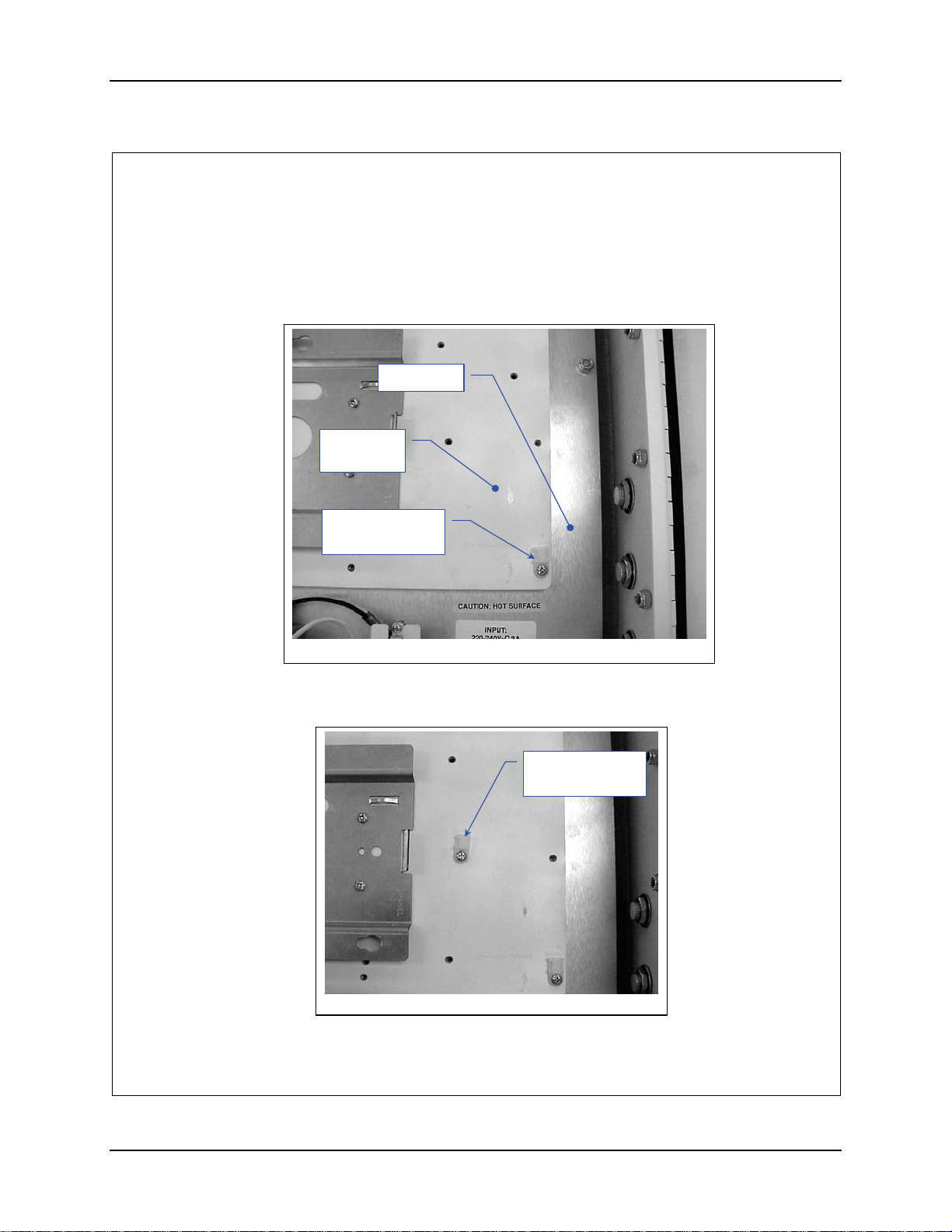
5. Remove the lower right screw holding the mounting plate to the base plate.
See figure 3.
6. Install one of the cable tie downs and secure it with the screw you removed
earlier.
Base Plate
Mounting
Plate
Cable Tie Down
Installed Here
Figure 3
7. Install the next cable tie near the AP bracket. See figure 4. Secure it with a
#6-32 screw.
Cable Tie Down
Installed Here
Figure 4
159088-0001 Rev. C Page 4 of 14
NEMA Type 4 Enclosure Reference Guide E-EQ-NEMARG-F
Page 81
Installation Procedure, LXE Model 6730 AP (non-RoHS) 73
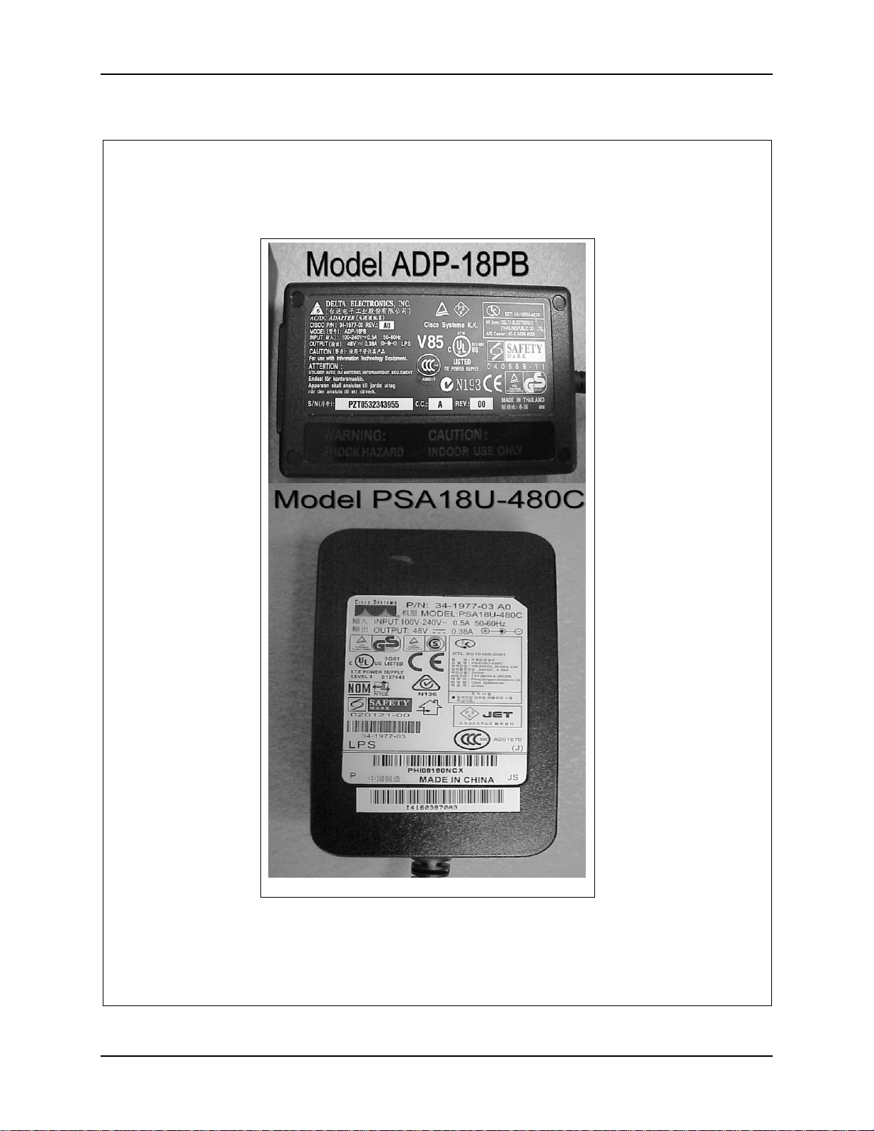
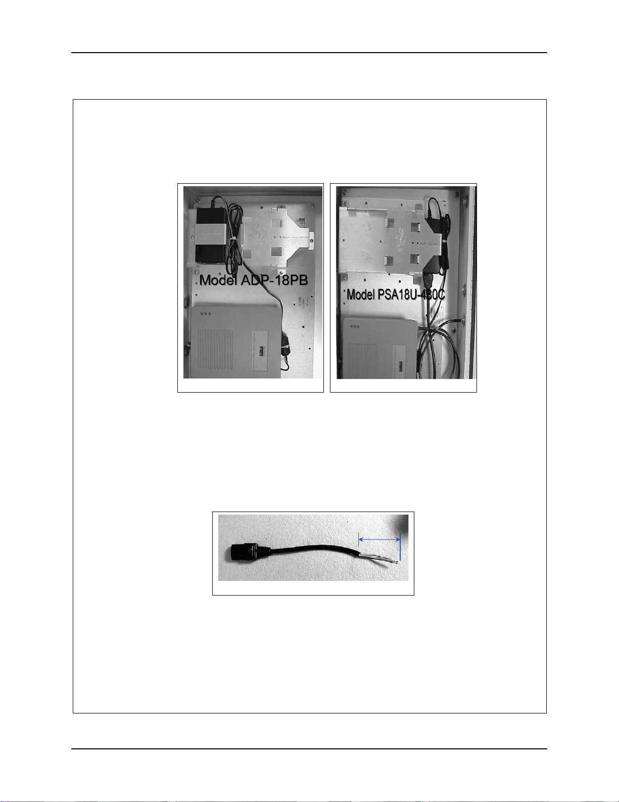
8. Determine which Model Power Brick Came with the AP. See figure 5.
Figure 5
9. For Model ADP-18PB skip to step 16.
159088-0001 Rev. C Page 5 of 14
E-EQ-NEMARG-F NEMA Type 4 Enclosure Reference Guide
Page 82
74 Installation Procedure, LXE Model 6730 AP (non-RoHS)
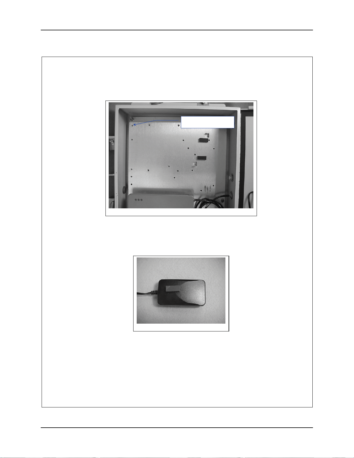
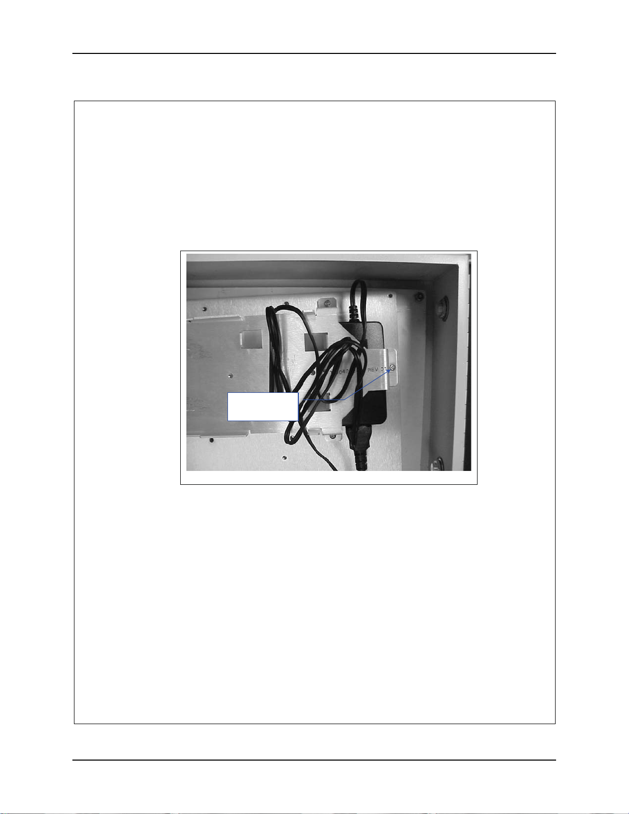
10. Install two (2) of the Foam Pads on the mounting plate. See figure 6.
Remove this screw
Figure 6
11. Remove the screw from the upper left corner of the Mounting Plate. See
figure 6.
12. Apply the remaining Foam Pad to the top of the Power brick as shown in
figure 7.
Figure 7
159088-0001 Rev. C Page 6 of 14
NEMA Type 4 Enclosure Reference Guide E-EQ-NEMARG-F
Page 83
Installation Procedure, LXE Model 6730 AP (non-RoHS) 75
13. Place the AP power supply on top of the foam pads placed on mounting plate
earlier with the AC power connector pointed towards the bottom of the
enclosure. See figure 8.
14. Position bracket 160042-0001 over the AP Power Brick. See figure 8.
15. Place a cable tie down over the screw hole on the right end of the bracket and
secure it with a 6-32 screw. See figure 8. (Skip to step 25)
Cable Tie
down here.
Figure 8
159088-0001 Rev. C Page 7 of 14
E-EQ-NEMARG-F NEMA Type 4 Enclosure Reference Guide
Page 84
76 Installation Procedure, LXE Model 6730 AP (non-RoHS)
16. Install power brick Model ADP-18PB
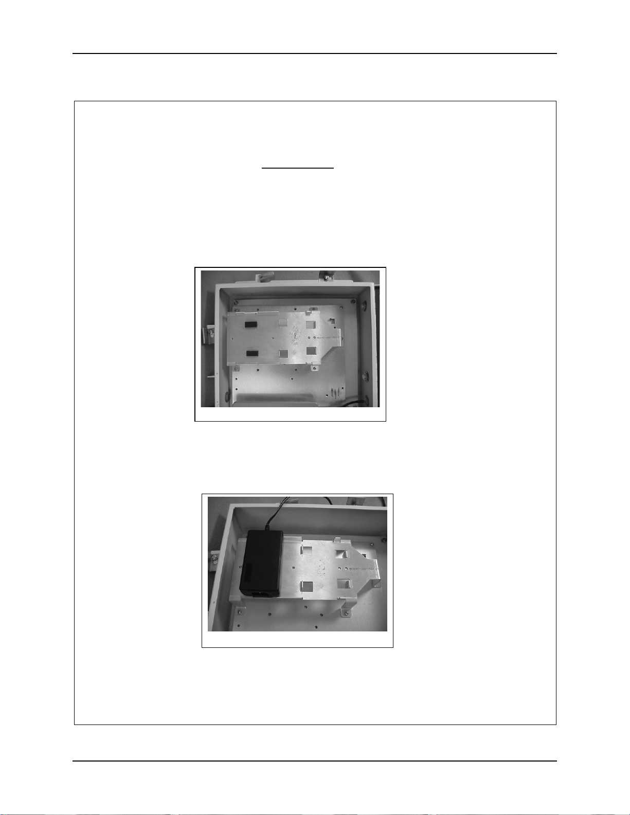
17. Remove the screw from the upper left corner of the Mounting Plate. See
figure 6.
18. Position bracket 160042-0001 in the upper area of the enclosure. See figure 9.
19. Secure the bracket with four (4) 6-32 x 5/16” long screws and the one that was
removed form the Mounting Plate earlier.
Figure 9
20. Remove the adhesive backing and apply two (2) of the Foam Pads to Bracket,
160042-0001, as shown in figure 9. Discard the remaining Foam Pad.
.
21. Position the AC Power Brick over the Foam Pads with the AC input pointing
towards the bottom of the box. See figure 10.
Figure 10
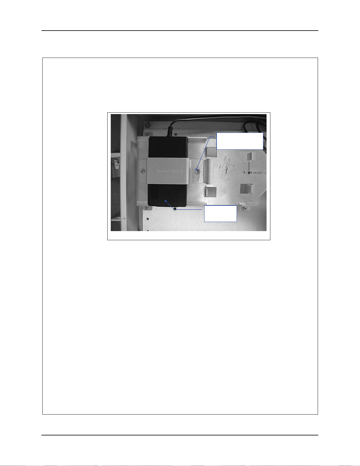
22. Place bracket 160043-0001 over the Power Brick. See figure 11.
159088-0001 Rev. C Page 8 of 14
NEMA Type 4 Enclosure Reference Guide E-EQ-NEMARG-F
Page 85
Installation Procedure, LXE Model 6730 AP (non-RoHS) 77
23. Place a nylon tie down over the screw hole to the right of the power brick.
See figure 11.
Cable Tie Down
Installed Here
AC power
connector
Figure 11
24. Secure the bracket and tie down with two (2) 6-32 x 5/16” screws.
159088-0001 Rev. C Page 9 of 14
E-EQ-NEMARG-F NEMA Type 4 Enclosure Reference Guide
Page 86
78 Installation Procedure, LXE Model 6730 AP (non-RoHS)
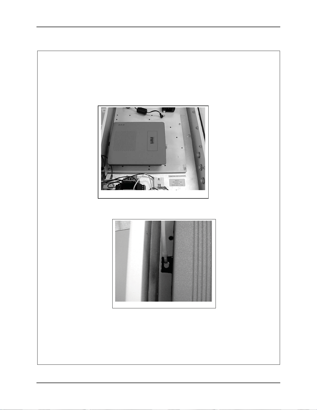
25. Place the AP on top of the AP Mounting bracket. See figure 12
26. Align the AP up with the slots in the AP mounting bracket and slide it to the
left to engage the pins.
Figure 12
27. Secure the AP with an 8” cable tie. See figure 13. Slide the tie through the
slot located on the left side of the AP and pull it tight and trim.
Figure 13
159088-0001 Rev. C Page 10 of 14
NEMA Type 4 Enclosure Reference Guide E-EQ-NEMARG-F
Page 87
Installation Procedure, LXE Model 6730 AP (non-RoHS) 79
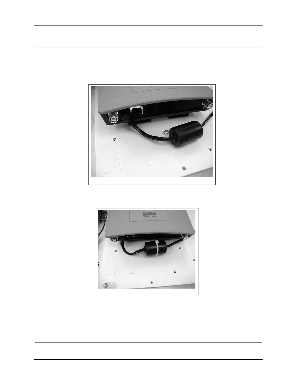
28. Plug the power brick output cord into the AP. See figure 14.
Figure 14
29. Secure the ferrite to the tie down with one of the 8” nylon cable ties. See
figure 15. Trim the nylon tie after pulling it tight.
Figure 15
159088-0001 Rev. C Page 11 of 14
E-EQ-NEMARG-F NEMA Type 4 Enclosure Reference Guide
Page 88
80 Installation Procedure, LXE Model 6730 AP (non-RoHS)
30. Bundle the excess cord as shown and tie it down with an 8” nylon tie to the tie
down near the power brick. See figure 16.
Figure 16a
31. Trim the nylon tie after pulling it tight.
32. Obtain the power cord supplied with the AP.
33. Measure 21” from the universal plug end of the AC power cord (supplied with
the AP) and cut. Discard the remainder of the cord.
34. Remove at least 2” inches of the outer covering from the cut end of the cord.
See figure 17.
Figure 17
35. Remove 0.4” (10 mm) of the insulation from each conductor.
36. Plug the power cord into the power supply brick
Figure 16b
2”
159088-0001 Rev. C Page 12 of 14
NEMA Type 4 Enclosure Reference Guide E-EQ-NEMARG-F
Page 89
Installation Procedure, LXE Model 6730 AP (non-RoHS) 81
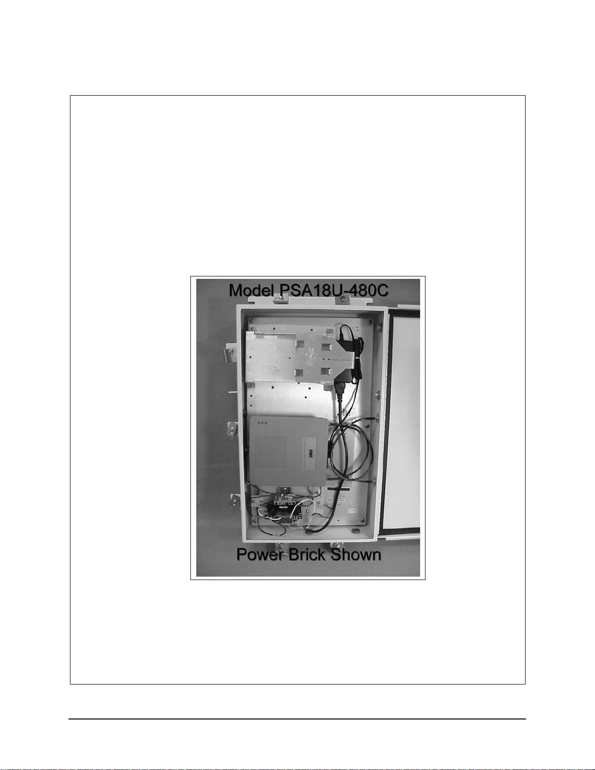
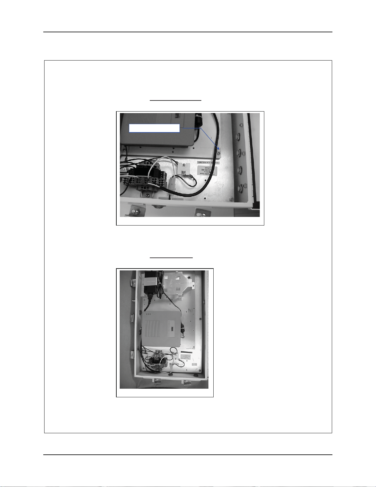
37. For power brick Model PSA18U-480C
block located in the lower left corner of the enclosure. See figure 18.
Figure 18
38. Secure the cord with an 8” Nylon tie to the tie down in the lower right corner
of the mounting plate. See figure 18.
39. For power brick Model ADP-18PB
block located in the lower left corner of the enclosure. See figure 19.
, route the power cord to the terminal
, route the power cord to the terminal
Figure 19
159088-0001 Rev. C Page 13 of 14
E-EQ-NEMARG-F NEMA Type 4 Enclosure Reference Guide
Page 90
82 Installation Procedure, LXE Model 6730 AP (non-RoHS)
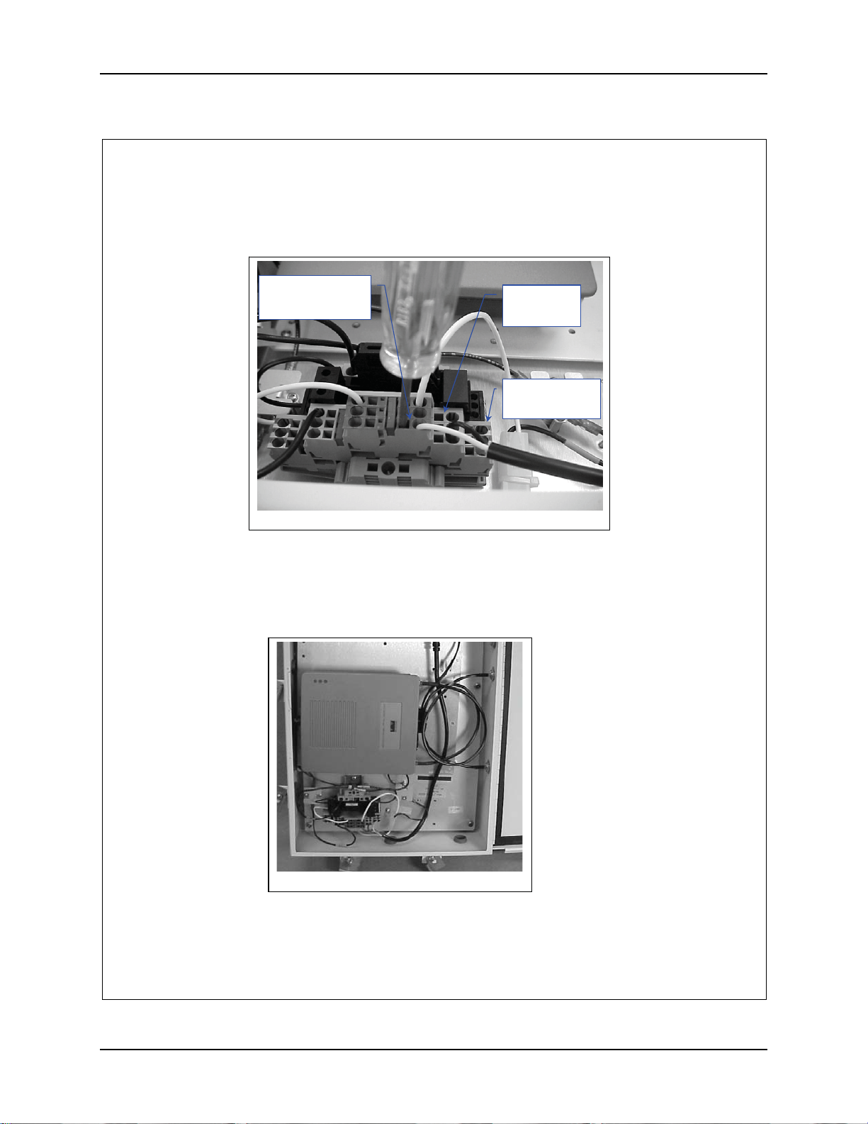
40. Insert the conductors into the terminal block. White to Neutral (marked blue)
Black to Live (unmarked) Ground to Ground (marked green). See figure 20.
Neutral
Marked Blue
Figure 20
41. Remove the two (2) lower plugs opposite the AP from the side of the
enclosure.
42. Install the antenna cables in the holes and tighten.
43. Route the cables to the AP and connect them to the AP. See figure 21.
Live
Unmarked
Ground
Marked Green
Figure 21
44. Connect Power and Data cables per installation manual.
159088-0001 Rev. C Page 14 of 14
NEMA Type 4 Enclosure Reference Guide E-EQ-NEMARG-F
Page 91
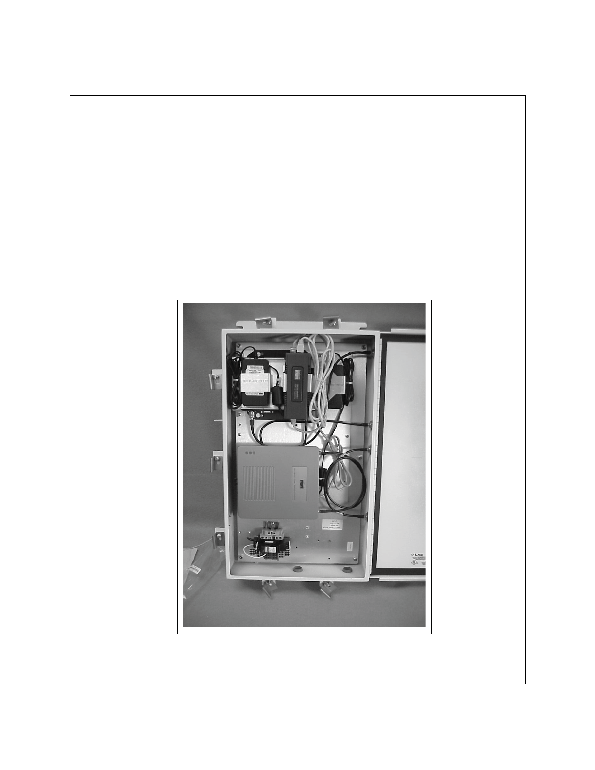
Installation Procedure, LXE Models 6723 Bridge & 6730 AP (non-RoHS)
159089-0001
Rev. C
INSTALLATION PROCEDURE
LXE Model 6723 Bridge, Cisco 350 Bridge
&
LXE Model 6730 AP, Cisco 1200 AP
NEMA 4 ENCLOSURE
159089-0001 Rev. C Page 1 of 15
E-EQ-NEMARG-F NEMA Type 4 Enclosure Reference Guide
Page 92
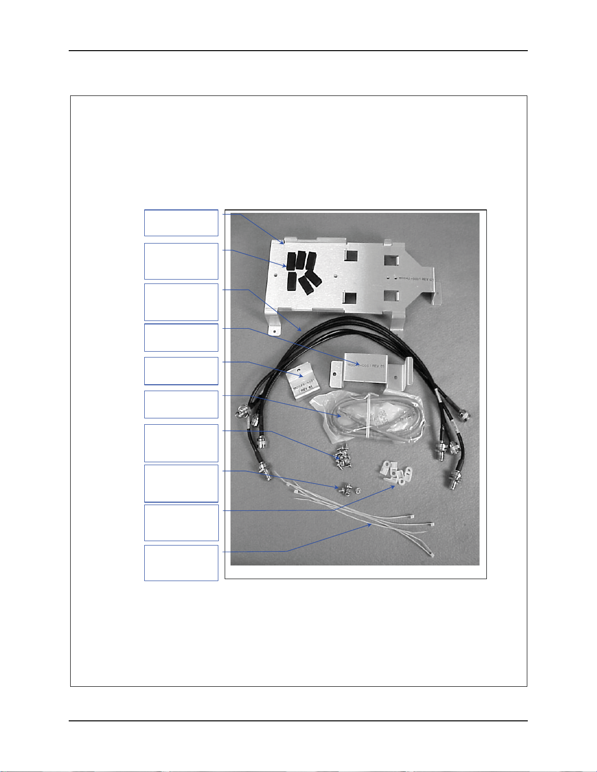
84 Installation Procedure, LXE Models 6723 Bridge & 6730 AP (non-RoHS)
(
)
Qty
Qty
Qty
1. Remove the hardware package from the enclosure.
2. Remove contents and verify the quantities. See figure 1.
Bracket, Qty. 1
160042-0001
Pad, Foam
(155154-0001)
. 6
Antenna Cable
(158877-0001)
Qty. 4
Bracket, Qty. 1
(160043-0001)
Bracket, Qty. 1
(160046-0001)
Crossover cable,
(425042-0836)
#6-32 Screw,
5/16”lg. Qty 14
(137646-0606)
#8-32 Screw,
1/4”long. Qty 4
(137646-0804)
Nylon Tie Down
(703006-0000)
. 6
8” Nylon Tie
(703028-0000)
. 6
Figure 1
159089-0001 Rev. C Page 2 of 15
NEMA Type 4 Enclosure Reference Guide E-EQ-NEMARG-F
Page 93
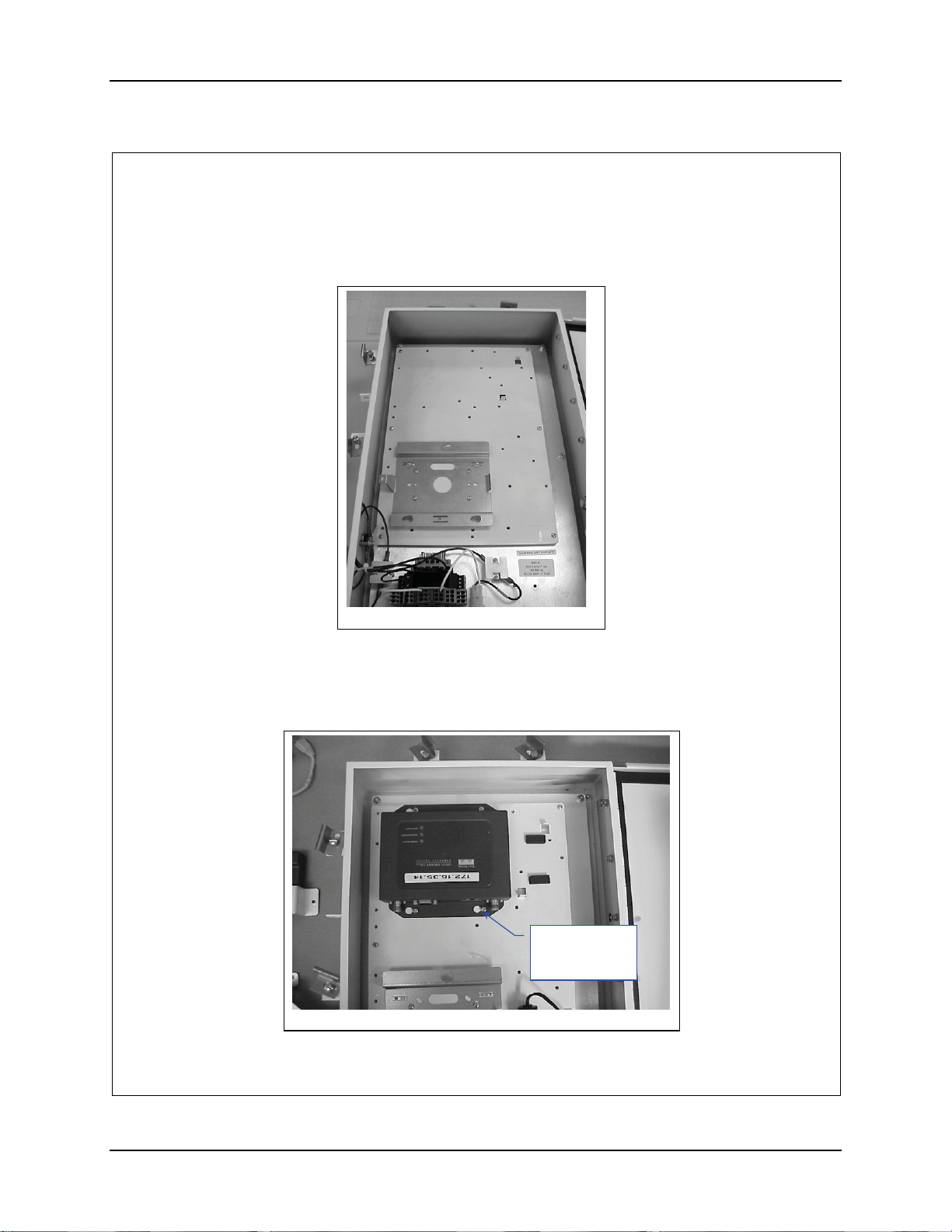
Installation Procedure, LXE Models 6723 Bridge & 6730 AP (non-RoHS) 85
3. Locate the 6730 Mounting Bracket (Cisco 1200), supplied with the AP, on the
AP Mounting Plate. See figure 2.
Figure 2
4. Secure the AP Mounting Bracket to the AP Mounting Plate with four (4) 6-32
screws. See figure 2.
5. Locate the 6723 Bridge (Cisco 350) on the AP Mounting Plate above the AP
bracket, with the antenna connectors towards the bottom. See figure 3.
#8-32 Screw ¼”
long. Qty. 4
Figure 3
159089-0001 Rev. C Page 3 of 15
E-EQ-NEMARG-F NEMA Type 4 Enclosure Reference Guide
Page 94
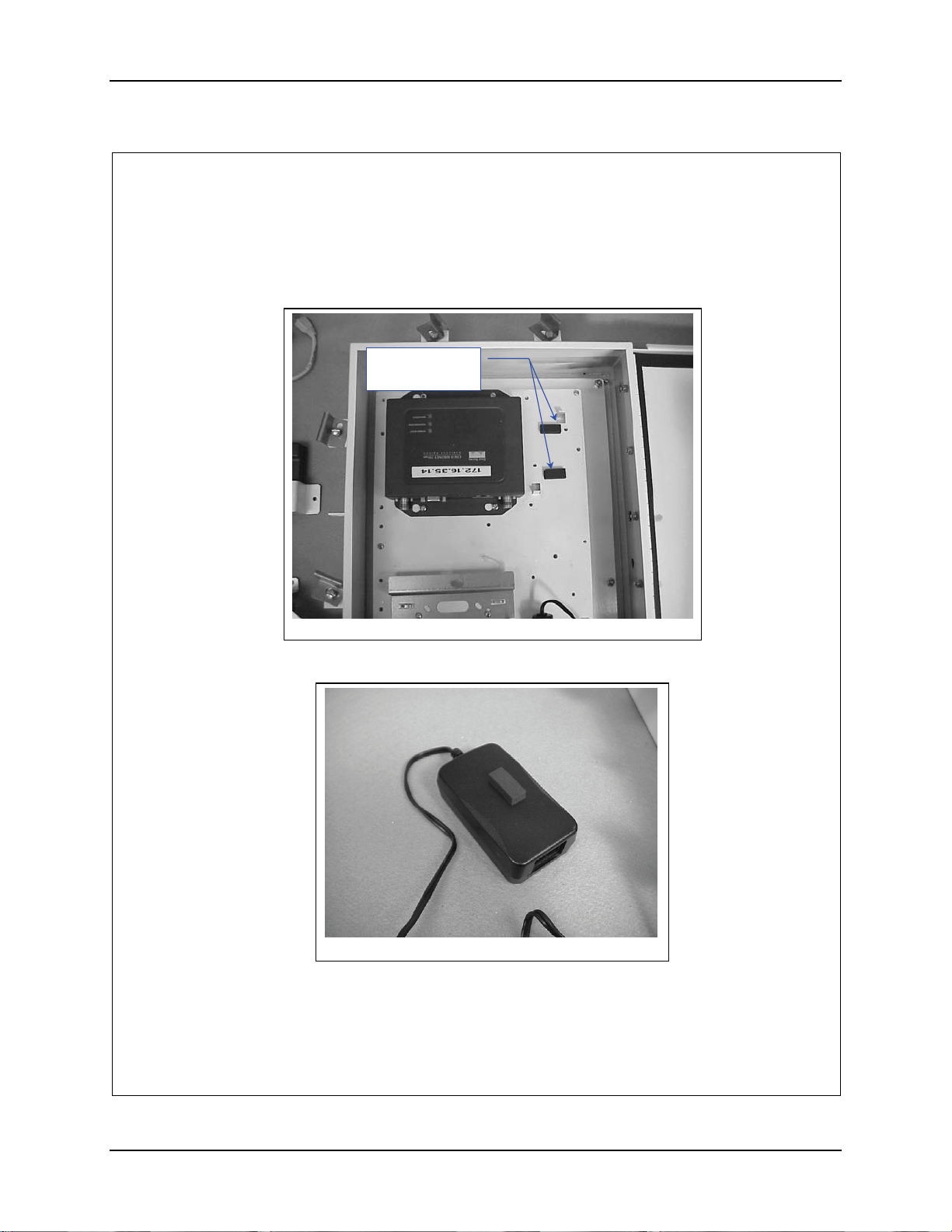
86 Installation Procedure, LXE Models 6723 Bridge & 6730 AP (non-RoHS)
6. Secure the Bridge in place with four (4) 8-32 screws.
7. Apply two (2) foam pads, 155145-0001, to the AP Mounting Plate as shown
in figure 4.
Foam Pads,
155154-0001
Figure 4
8. Apply a single foam pad to the AP Power Brick. See figure 5.
Figure 5
159089-0001 Rev. C Page 4 of 15
NEMA Type 4 Enclosure Reference Guide E-EQ-NEMARG-F
Page 95
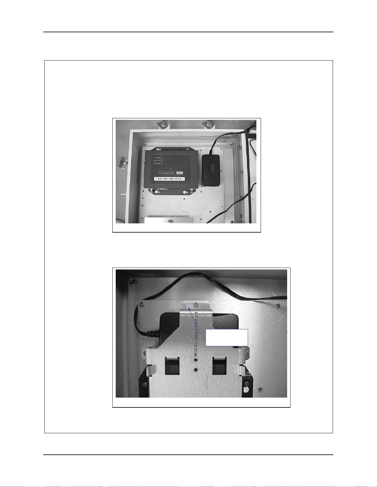
Installation Procedure, LXE Models 6723 Bridge & 6730 AP (non-RoHS) 87
9. Position the Power Brick on top of the two foam pads, between the bent up
tabs with the AC power connector pointed towards the bottom of the
enclosure. See figure 6.
Figure 6
10. Position bracket 160042-0001 over the Bridge and the AP Power Brick. See
figure 7.
11. Place a cable tie down over the screw hole on the right end of the bracket and
secure it with a 6-32 screw. See figure 7.
Cable Tie
down here.
Figure 7
159089-0001 Rev. C Page 5 of 15
E-EQ-NEMARG-F NEMA Type 4 Enclosure Reference Guide
Page 96
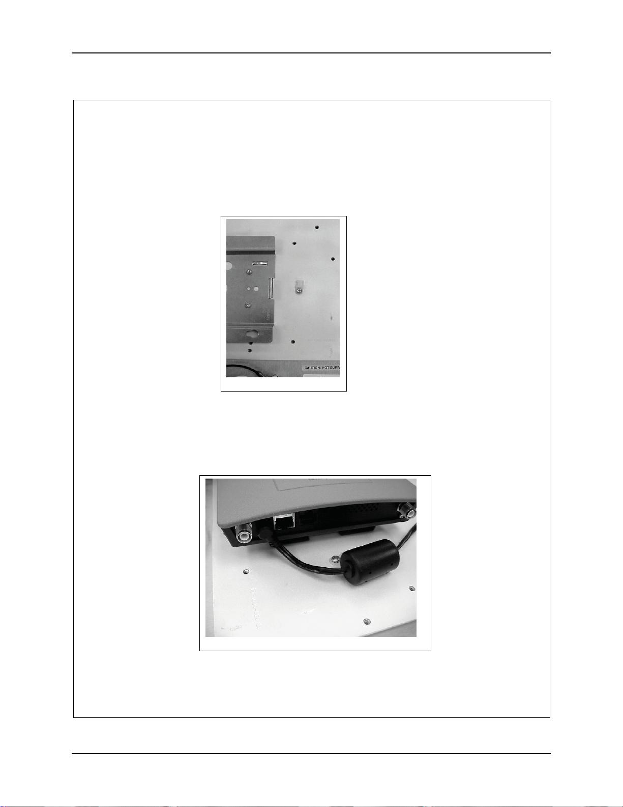
88 Installation Procedure, LXE Models 6723 Bridge & 6730 AP (non-RoHS)
12. Secure the bracket with four (4) 6-32 screws 5/16” long.
13. Install a cable tie down in the AP Mounting Plate near the AP Bracket and
secure it with a 6-32 screw. See figure 8.
Figure 8
14. Place the AP on top of the AP Mounting Bracket. See figure 9.
15. Align the AP up with the slots in the AP Mounting Bracket and slide it to the
left to engage the pins.
16. Route the power connector to the AP and plug it into the AP. See figure 9.
Figure 9
159089-0001 Rev. C Page 6 of 15
NEMA Type 4 Enclosure Reference Guide E-EQ-NEMARG-F
Page 97
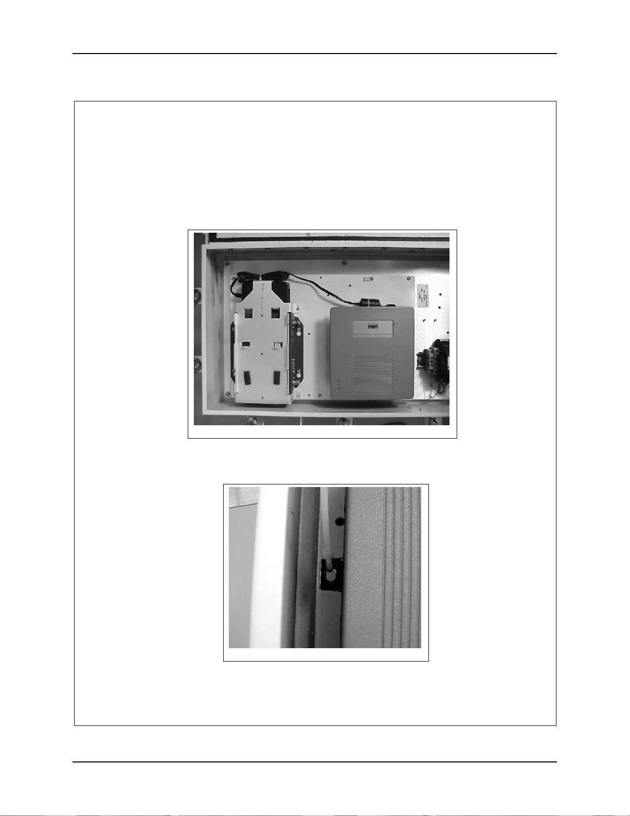
Installation Procedure, LXE Models 6723 Bridge & 6730 AP (non-RoHS) 89
17. Secure the Ferrite on the power cord to the AP Mounting Plate with an 8”
nylon cable tie.
18. Bundle the power cord up and cable tie it to the tie down near the Power
Brick. See figure 10.
Figure 10
19. Secure the AP with an 8” cable tie. See figure 11. Slide the tie through the
slot located on the left side of the AP and pull it tight and trim.
Figure 11
159089-0001 Rev. C Page 7 of 15
E-EQ-NEMARG-F NEMA Type 4 Enclosure Reference Guide
Page 98
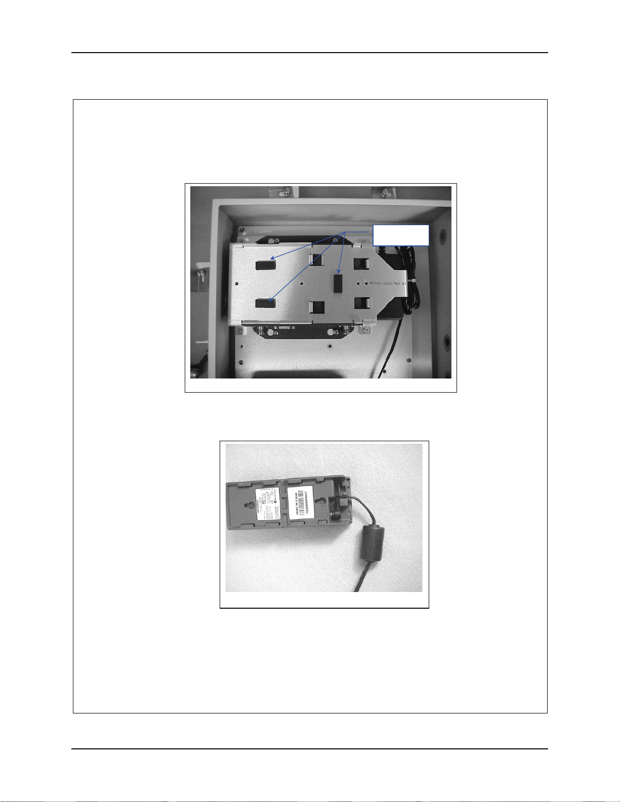
90 Installation Procedure, LXE Models 6723 Bridge & 6730 AP (non-RoHS)
20. Remove the adhesive backing and apply three (3) of the Foam Pads to
Bracket, 160042-0001, as shown in figure 12.
Foam Pads
Figure 12
21. Plug the output power cord from the Power Brick into the Power Injector and
route cable as shown in figure 13.
Figure 13
22. Position the AC Power Brick over the Foam Pads with the label side (bottom)
up and the AC input pointing towards the bottom of the box. See figure 14.
159089-0001 Rev. C Page 8 of 15
NEMA Type 4 Enclosure Reference Guide E-EQ-NEMARG-F
Page 99
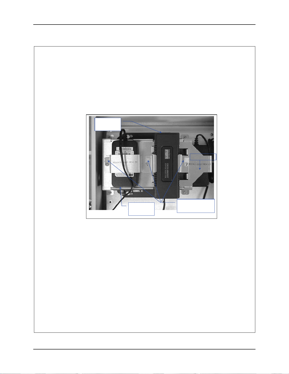
Installation Procedure, LXE Models 6723 Bridge & 6730 AP (non-RoHS) 91
23. Position the Power Injector over the Foam Pad on bracket 160042-0001 and
up against the locating tabs with the RJ45 jacks pointed towards the top of the
box. See Figure 14.
24. Place brackets 160043-0001 and 160046-0001 over the Power Brick and
Injector. See figure 14.
25. Place a nylon tie down over the screw holes of the brackets. See figure 14.
Network
RJ45 Conn.
AC power
Figure 14
26. Secure the tie downs and the bracket with three (3) 6-32x 5/16” long screws.
159089-0001 Rev. C Page 9 of 15
connector
Cable Tie Down
Installed Here
E-EQ-NEMARG-F NEMA Type 4 Enclosure Reference Guide
Page 100
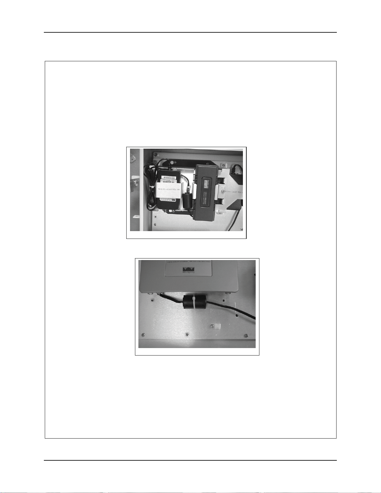
92 Installation Procedure, LXE Models 6723 Bridge & 6730 AP (non-RoHS)
27. Route the power cord from the Power Injector between the Power Brick and
the Power Injector and secure the ferrite with a nylon cable tie. See Figure 15.
28. Route the power cord around the top of the Power Brick.
29. Bundle it and secure it with a nylon cable tie on the LEFT side of the Power
Brick. See figure 15.
Figure 15
30. Install a cable tie down on the AP Mounting Plate for the Crossover Cable.
See figure 16.
Figure 16
31. Connect the Crossover Cable to the AP and route it to the network input on
the Power Injector for the Bridge. See figure 16a and 16b.
159089-0001 Rev. C Page 10 of 15
NEMA Type 4 Enclosure Reference Guide E-EQ-NEMARG-F
 Loading...