

Page 1
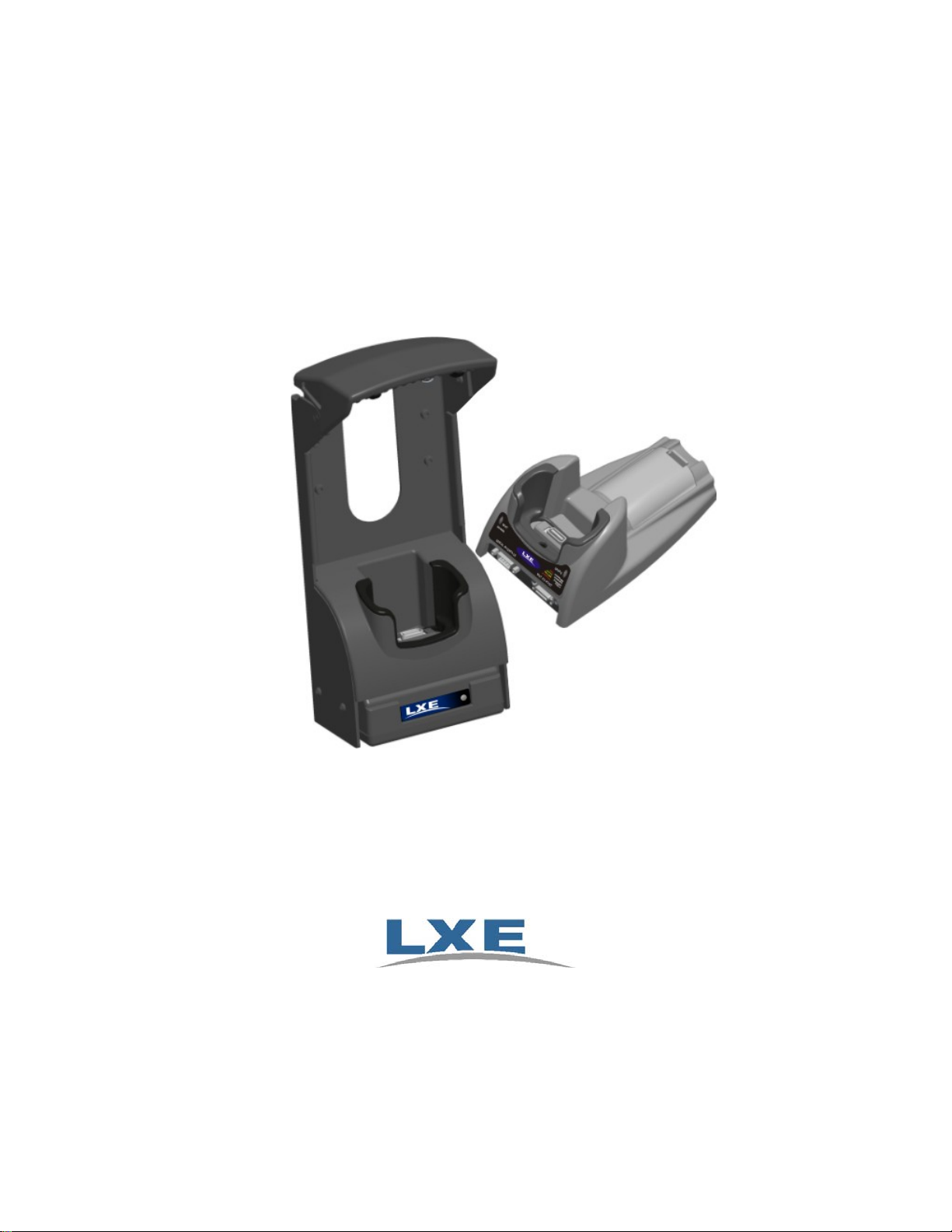
MX7 Cradle Reference Guide
Copyright © 2008 by LXE Inc.
All Rights Reserved
E-EQ-MX7DKRG-C
Page 2
Notices
LXE Inc. reserves the right to make improvements or changes in the products described in this document at any
time without notice. While reasonable efforts have been made in the preparation of this document to assure its
accuracy, LXE assumes no liability resulting from any errors or omissions in this document, or from the use of the
information contained herein. Further, LXE Incorporated, reserves the right to revise this document and to make
changes to it from time to time without any obligation to notify any person or organization of such revision or
changes.
Copyright:
This manual is copyrighted. All rights are reserved. This document may not, in whole or in part, be copied,
photocopied, reproduced, translated or reduced to any electronic medium or machine-readable form without prior
consent, in writing, from LXE Inc. Further, LXE Incorporated, reserves the right to revise this publication and to
make changes to it from time to time without any obligation to notify any person or organization of such revision or
changes.
Copyright © 2008 by LXE Inc. An EMS Technologies Company.
125 Technology Parkway, Norcross, GA 30092 U.S.A. (770) 447-4224
Trademarks:
LXE® and Spire® are registered trademarks of LXE Inc.
RAM® and RAM Mount™ are both trademarks of National Products Inc., 1205 S. Orr Street, Seattle, WA 98108.
The Bluetooth® word mark and logos are owned by the Bluetooth SIG, Inc. and any use of such marks by LXE,
Inc. is under license.
PowerScan® is a registered trademark of Datalogic Scanning, Inc., located in Eugene, OR.
Symbol® is a registered trademark of Symbol Technologies. MOTOROLA® and the Stylized M Logo are
registered trademarks of Motorola®, Inc.
All other brand or product names are trademarks or registered trademarks of their respective companies or
organizations.
When this manual is in PDF format: “Acrobat ® Reader Copyright © 1987-2008 Adobe Systems Incorporated. All
rights reserved. Adobe, the Adobe logo, Acrobat, and the Acrobat logo are trademarks of Adobe Systems
Incorporated.” Applies.
Important: This symbol is placed on the product to remind users to dispose of Waste Electrical and Electronic
Equipment (WEEE) appropriately, per Directive 2002-96-EC. In most areas, this product can be recycled,
reclaimed and re-used when properly discarded. Do not discard labeled units with trash. For information about
proper disposal, contact LXE through your local sales representative, or visit www lxe com.
Caution
Attention
RISK OF EXPLOSION IF BATTERY IS REPLACED BY AN INCORRECT TYPE.
DISPOSE OF USED BATTERIES ACCORDING TO THE INSTRUCTIONS.
II y a danger d’explosion s’il y a remplacement incorrect de la batterie. Remplacer
uniquement avec une batterie du même type ou d’un type equivalent
recommandé par le constructeur. Mettre au rebut les batteries usagées
conformément aux instructions du fabricant.
Revision Notice - Rev C: The MX7 Passive Cradle does not secure an MX7 with a boot, but will secure an MX7
with a handle or a strap.
Revision Notice - Rev B: Added Powered Vehicle Mount Cradle and related Accessories. Updated Regulatory
Notices and Safety Statements.
Page 3

Table of Contents
MX7 CRADLES 1
Introduction............................................................................................................................................1
Suggestions / Notes ..............................................................................................................................1
Desktop Cradle.......................................................................................................................................2
Powered Vehicle Mounted Cradle........................................................................................................2
Passive Vehicle Mounted Cradle..........................................................................................................3
Desktop Cradle LEDs ............................................................................................................................4
MX7 Docked LED................................................................................................................................................4
Spare Battery LED................................................................................................................................................4
MX7 Mobile Device System Status LED ............................................................................................................. 4
Powered Vehicle Mount Cradle LEDs..................................................................................................5
Vehicle Cradle LED.............................................................................................................................................. 5
MX7 Mobile Device System Status LED ............................................................................................................. 5
Tethered Scanners and the MX7 Cradles............................................................................................6
Maintenance........................................................................................................................................... 7
Desktop Cradles....................................................................................................................................................7
Vehicle Mounted Cradles .....................................................................................................................................7
Cleaning ................................................................................................................................................................ 7
MX7 Base Plate Replacement...............................................................................................................................8
Identify Your MX7 Base Plate...........................................................................................................................8
Upgrade The Base Plate.....................................................................................................................................8
Getting Help..........................................................................................................................................10
Manuals............................................................................................................................................................... 10
Accessories .........................................................................................................................................................10
DESKTOP CRADLE 13
Quick Start - Desktop Cradle..............................................................................................................13
Suggestions / Notes............................................................................................................................................. 13
Components......................................................................................................................................... 14
Desktop Mounting Footprint...............................................................................................................16
Preparing the Desktop Cradle for Use...............................................................................................16
Install / Remove MX7 Desktop Cradle Adapter Cup......................................................................... 17
Cabling the Desktop Cradle................................................................................................................18
Assemble/Attach the AC Power Adapter............................................................................................................18
Attach a Serial or I/O Connector.........................................................................................................................19
Serial Cable ......................................................................................................................................................19
I/O Cable..........................................................................................................................................................19
Pinout - RS-232 Connector ..............................................................................................................................20
Docking and Undocking the MX7.......................................................................................................21
Battery Charging in a Desktop Cradle...............................................................................................21
Technical Specifications – Desktop Cradle...................................................................................... 21
Insert / Remove a Spare Battery.........................................................................................................22
POWERED VEHICLE MOUNT CRADLE 23
Introduction..........................................................................................................................................23
Quick Start - Powered Vehicle Cradle ............................................................................................... 24
Components......................................................................................................................................... 24
Install / Remove Vehicle Cradle Adapter Cup and Top Adapter..................................................... 26
E-EQ-MX7DKRG-C MX7 Cradle Reference Guide
Page 4

ii Table of Contents
Install Adapter Assembly.................................................................................................................................... 26
Remove Adapter Assembly ................................................................................................................................28
Docking and Undocking the MX7.......................................................................................................29
RAM Bracket Mounting ....................................................................................................................... 30
RAM Circular Base Footprint............................................................................................................................. 31
Vehicle Cradle RAM Ball Assembly...................................................................................................32
Connect Power Supply to Vehicle......................................................................................................33
Vehicle 12V Bare Wire Adapter.........................................................................................................................33
Connect Power Supply to Vehicle Cradle ......................................................................................... 36
Vehicle Cradle LED............................................................................................................................................ 36
Attach a Serial or I/O Connector ........................................................................................................37
Serial Interface....................................................................................................................................................37
MX7 I/O Port ......................................................................................................................................................37
Vehicle Cradle Strain Relief Cable Clamp.........................................................................................38
Technical Specifications.....................................................................................................................39
Powered Vehicle Cradle .....................................................................................................................................39
Cradle Power Connector Port .............................................................................................................................39
Pinout - RS-232 Connector.................................................................................................................................40
PASSIVE VEHICLE MOUNT CRADLE 41
Introduction..........................................................................................................................................41
Quick Start - Passive Vehicle Cradle..................................................................................................................41
Components......................................................................................................................................... 42
U-Bracket.........................................................................................................................................................42
U-Bracket Footprint ......................................................................................................................................42
RAM Ball and Cylinder ...................................................................................................................................43
RAM Assembly Footprint.............................................................................................................................44
Install..................................................................................................................................................... 44
How to Install the Cradle U-Bracket...................................................................................................................44
How to Install the RAM Bracket ........................................................................................................................46
APPENDIX A REGULATORY NOTICES AND SAFETY INFORMATION 49
Cradle Approvals.................................................................................................................................49
INDEX 53
MX7 Cradle Reference Guide E-EQ-MX7DKRG-C
Page 5

Illustrations
Figure 1 Desktop Cradle ...................................................................................................................................... 2
Figure 2 Powered Vehicle Mounted Cradle.........................................................................................................2
Figure 3 Passive Vehicle Mounted Cradle...........................................................................................................3
Figure 4 Desktop Cradle Front Label ..................................................................................................................4
Figure 5 Powered Vehicle Cradle Front Label ....................................................................................................5
Figure 6 LXE Tethered Scanners (w/o cable)......................................................................................................6
Figure 7 Desktop Components...........................................................................................................................14
Figure 8 Top.......................................................................................................................................................15
Figure 9 Table Mounting Hole Guides .............................................................................................................16
Figure 10 MX7 Charging Pocket Adapter Cup ................................................................................................17
Figure 11 AC/DC 12V External Power Supply and 3-prong Cable ..................................................................18
Figure 12 Connect Power Cable to the Cradle................................................................................................... 18
Figure 13 Serial Connector and I/O Connector .................................................................................................19
Figure 14 Desktop Cradle RS-232 and Pinout....................................................................................................20
Figure 15 Spare Battery Charging Bay ..............................................................................................................22
Figure 16 Vehicle Mount Cradle – Front........................................................................................................... 24
Figure 17 Vehicle Mount Cradle – Back ...........................................................................................................25
Figure 18 Charging Pocket Adapter Cup...........................................................................................................26
Figure 19 Retainer Insert ...................................................................................................................................27
Figure 20 Adapter Assembly .............................................................................................................................28
Figure 21 MX7 Docking and Undocking ..........................................................................................................29
Figure 22 RAM Bracket Mounting Points – Cradle Back .................................................................................30
Figure 23 RAM Base Dimensions .....................................................................................................................31
Figure 24 RAM Bracket Components ...............................................................................................................32
Figure 25 Vehicle Power Connection Cable (Fuse Not Shown)........................................................................33
Figure 26 Connecting the Power Cable to the Vehicle......................................................................................34
Figure 27 Vehicle Connection Wiring Color Codes..........................................................................................35
Figure 28 Connect Power Adapter Cable to the Vehicle Cradle........................................................................36
Figure 29 Powered Vehicle Cradle Front Label ................................................................................................36
Figure 30 Serial Connector, Power and MX7 I/O Connector............................................................................37
Figure 31 Vehicle Cradle Strain Relief Cable Clamps ......................................................................................38
Figure 32 Slide Clamp Over Cable....................................................................................................................38
Figure 33 Cradle Power Connector Port............................................................................................................39
Figure 34 Power Connector Pinout.................................................................................................................... 39
Figure 35 Vehicle Cradle RS-232 and Pinout....................................................................................................40
Figure 36 Passive Vehicle Mount Cradle and U-Bracket ..................................................................................42
Figure 37 U-Bracket Mounting Dimensions......................................................................................................42
Figure 38 Passive Vehicle Mount Cradle / RAM Ball Assembly...................................................................... 43
Figure 39 RAM Bracket Components ...............................................................................................................43
Figure 40 RAM Assembly Dimensions .............................................................................................................44
Figure 41 Installing the Cradle U-Bracket.........................................................................................................44
Figure 42 Installing the RAM Assembly ...........................................................................................................46
E-EQ-MX7DKRG-C MX7 Cradle Reference Guide
Page 6

iv Table of Contents
MX7 Cradle Reference Guide E-EQ-MX7DKRG-C
Page 7

Introduction
MX7 Cradles
MX7 docking cradles restrain the MX7, re-charge batteries, and enable serial, audio or USB
communication with a PC, scanner, printer or other peripheral device. MX7 keypad data entries
can be mixed with cradle-tethered scanner barcode data entries while the MX7 is in a powered
cradle. Bluetooth device connection and use, while the MX7 is docked, are managed by the MX7
Control Panel Bluetooth program, not the cradle.
Using a wall AC adapter the desktop cradle can also recharge a spare MX7 battery in
approximately 4 hours. The MX7 battery recharging is managed by the docked MX7 power
management configuration. The MX7 can be either On or in Suspend Mode while in the cradles.
The MX7 Vehicle Mount cradles do not have spare battery charging capabilities. Special purpose
and power cables are available from LXE®.
Wireless host/client communications can occur whether the cradles are receiving external power
or not as wireless functions draw power from the main battery in the MX7.
The powered cradles are designed to secure an MX7 with or without a protective
(MX7A490PROTBOOTBLK or MX7A491PROTBOOTYEL), a handstrap and/or a
boot
trigger handle.
Important: Use the power cables provided with the MX7 cradle power supply
adapters. The adapters are incompatible with other MX7 power cables.
Suggestions / Notes
• Remove cables from the base of the MX7 before docking it in a desktop or powered
vehicle cradle.
• Review the Maintenance section titled MX7 Base Plate Replacement and install a new
base plate on the MX7 if necessary.
• Allow clearance above and behind the cradles for inserting an MX7 with a trigger handle.
• Allow clearance behind the cradles for cable connection ease. Allow clearance in front of
desktop cradles for serial and I/O cable connection ease.
• Route cradle cables to ensure they are protected from jostling, tugging or being
disconnected by objects moving nearby.
• Install the pocket insert in the powered cradle charging well for use with an MX7 without
a boot enclosure.
• Remove the cradle insert for use with an MX7 with a boot enclosure.
• Use care when inserting the spare battery into the desktop charging bay. Do not slam the
battery into the bay, as this action could damage the contacts at the base of the charging
bay.
• Keep dirt and foreign objects out of the cradle. Do not short circuit any of the charging
terminals (pins), as this action could result in injury or property damage.
• Refer to the MX7 Reference Guide for information and instruction when using Bluetooth
scanning or printing devices with an MX7 docked in a powered or non-powered cradle.
MX7 Cradles are not certified for use in Hazardous Locations.
E-EQ-MX7DKRG-C MX7 Cradle Reference Guide
Page 8
2 Desktop Cradle
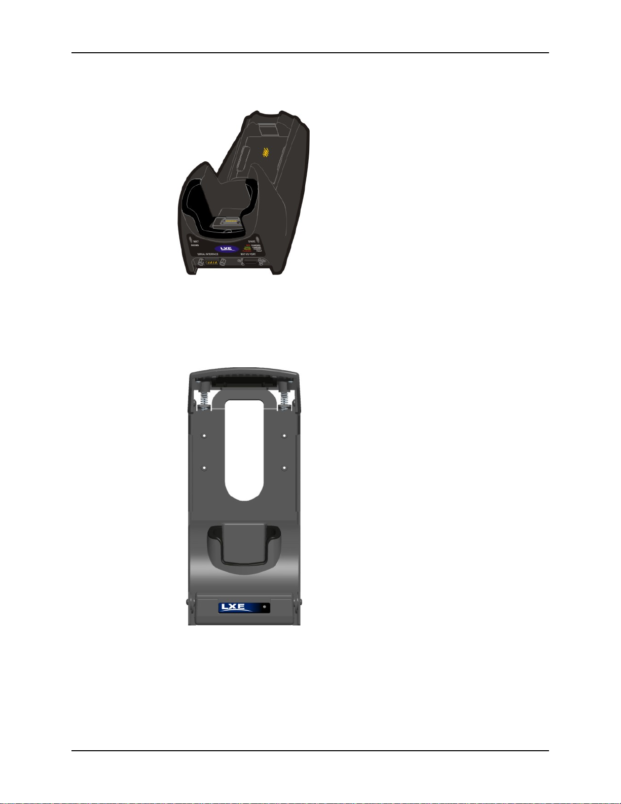
Desktop Cradle
The MX7 Desktop Cradle requires external
power before battery charging and tethered
scanning can commence. The cradle can
charge both the main battery in the docked
MX7 and a spare main battery at the same
time.
Figure 1 Desktop Cradle
See section titled Desktop Cradle, for more information and installation instruction.
Powered Vehicle Mounted Cradle
Figure 2 Powered Vehicle Mounted Cradle
The Powered Vehicle Cradle requires an
external power source before docked MX7
battery charging and tethered scanning
can commence.
See section titled Powered Vehicle Mounted Cradle, for more information and installation
instruction.
MX7 Cradle Reference Guide E-EQ-MX7DKRG-C
Page 9
Passive Vehicle Mounted Cradle 3
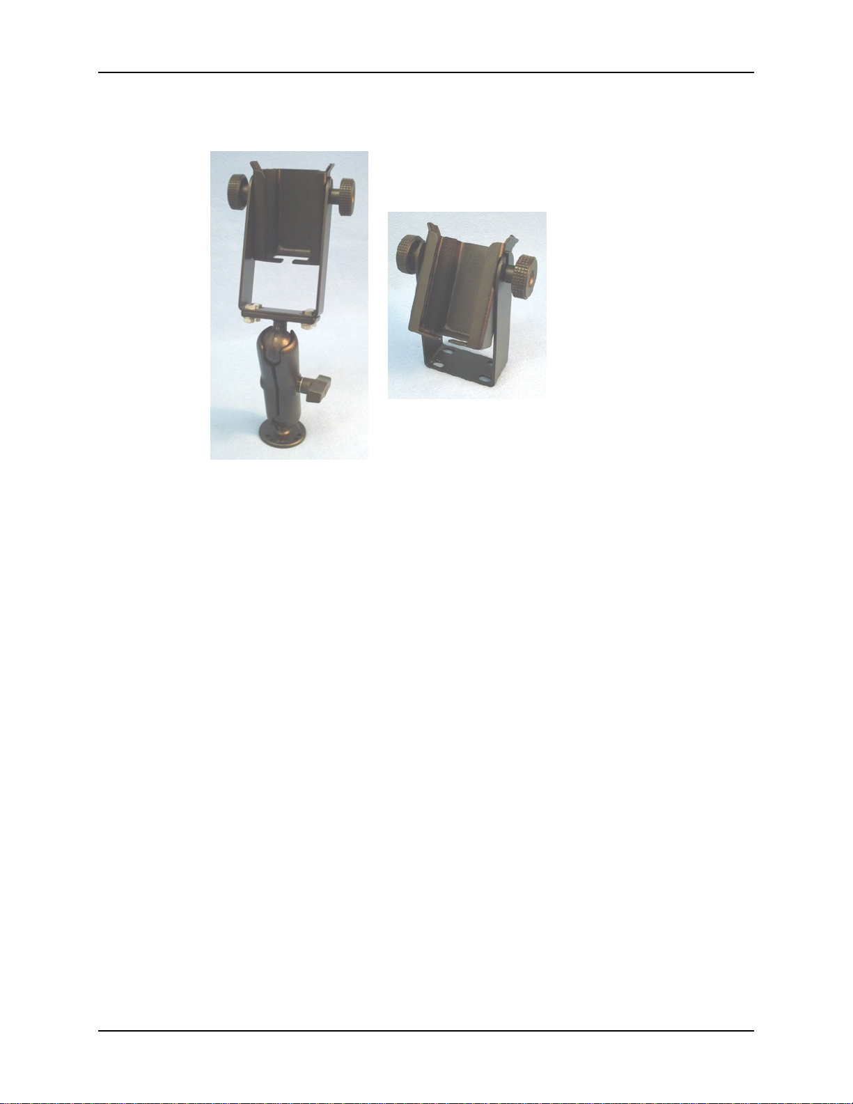
Passive Vehicle Mounted Cradle
The Passive Vehicle Cradle
does not have connectors
that can accept an external
power source or tethered
scanner. It is designed to
secure the MX7 in a
vehicle.
Figure 3 Passive Vehicle Mounted Cradle
See chapter titled Passive Vehicle Mounted Cradle for more information and installation
instruction.
E-EQ-MX7DKRG-C MX7 Cradle Reference Guide
Page 10
4 Desktop Cradle LEDs
Desktop Cradle LEDs
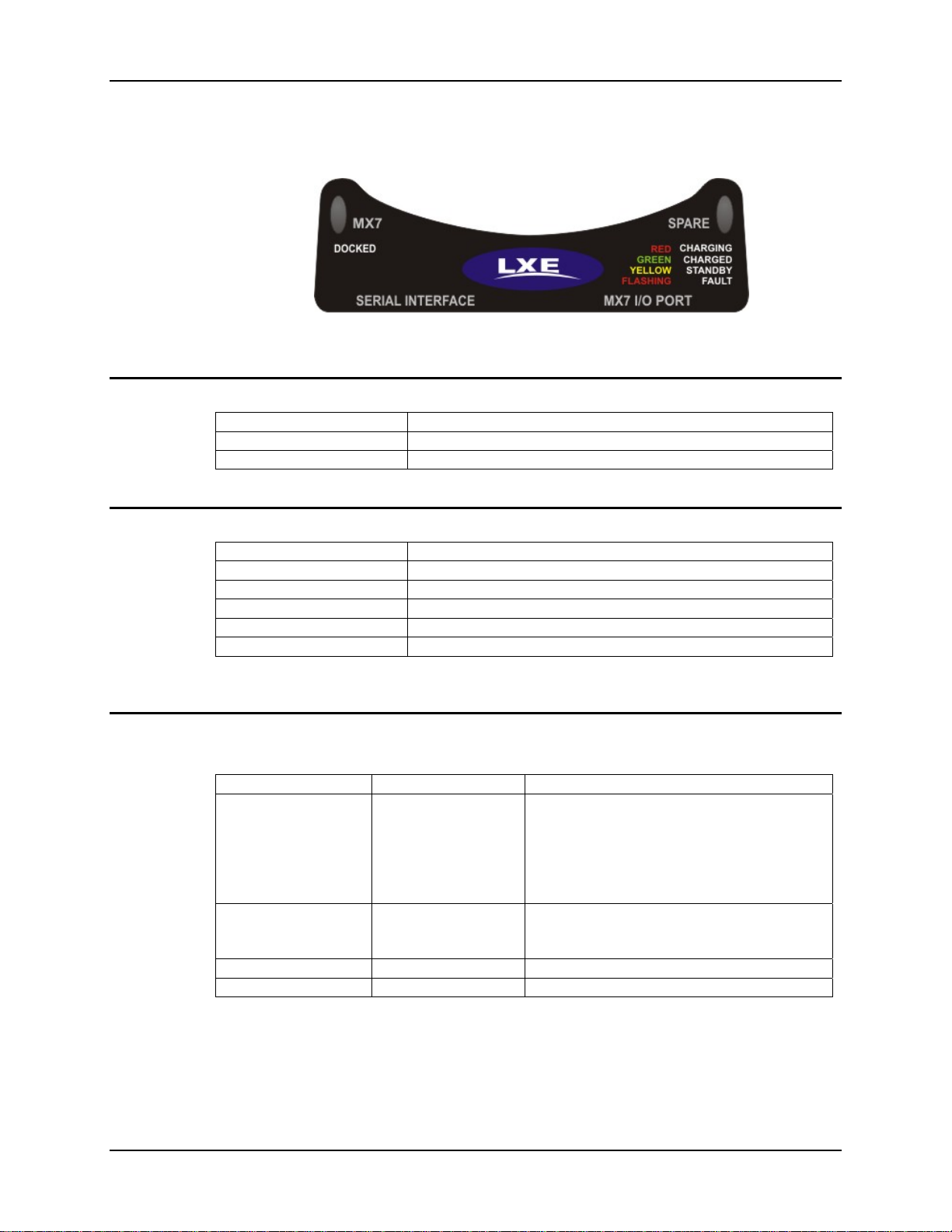
Figure 4 Desktop Cradle Front Label
MX7 Docked LED
When Docked LED is … It means ….
Off
Red
The cradle must be connected to AC power.
MX7 not inserted or no power applied
MX7 docked and power applied.
Spare Battery LED
When Spare LED is … It means ….
Off
Green
Red
Yellow / Amber
Flashing Red
The cradle must be connected to AC power. This process does not require an MX7 be in the
docking bay.
Battery pack not inserted or no power applied
Battery pack fully charged
Battery pack charging
Battery pack temperature out of range
Battery pack fault or failure
MX7 Mobile Device System Status LED
The MX7 System Status LED is located at the top left of the keypad, above the Scan button.
When the LED is . . . The Status is . . . Comment
Blinking Red
Steady Red
Blinking Green
No Color
Power Fail
Main Battery Low
Display Off No user intervention required.
Good No user intervention required.
Replace the main battery with a fully charged
main battery.
Or
Connect the MX7 to external AC power to
allow the internal charger to charge the main
battery e.g. dock in a powered cradle.
Low Battery Warning. Replace the main
battery with a fully charged main battery. Or
dock the MX7 in a powered cradle.
Note: The Passive Vehicle Cradle does not have LEDs.
MX7 Cradle Reference Guide E-EQ-MX7DKRG-C
Page 11
Powered Vehicle Mount Cradle LEDs 5
Powered Vehicle Mount Cradle LEDs
On Off
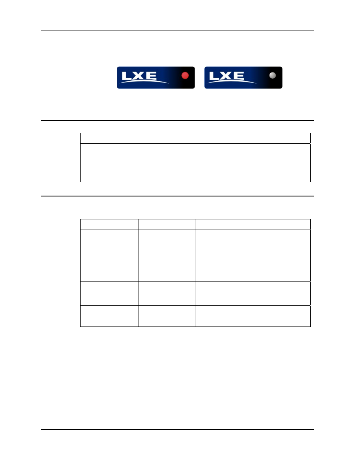
Figure 5 Powered Vehicle Cradle Front Label
Vehicle Cradle LED
When Cradle LED is … It means ….
1. MX7 is docked. Cradle does not have power.
Off
2. MX7 is not docked. Cradle may have power. Check the
power connector at the back of the cradle.
Red
MX7 is docked and external power is available.
MX7 Mobile Device System Status LED
The MX7 System Status LED is located at the top left of the keypad, above the Scan button.
When the LED is . . . The Status is . . . Comment
Blinking Red
Steady Red
Blinking Green
No Color
Note: The Passive Vehicle Cradle does not have LEDs.
Power Fail
Main Battery Low
Display Off No user intervention required.
Good No user intervention required.
Replace the main battery with a fully charged
main battery.
Or
Connect the MX7 to external AC power to
allow the internal charger to charge the main
battery e.g. insert in a powered cradle.
Low Battery Warning. Replace the main
battery with a fully charged main battery. Or
dock the MX7 in a powered cradle.
E-EQ-MX7DKRG-C MX7 Cradle Reference Guide
Page 12
6 Tethered Scanners and the MX7 Cradles
Tethered Scanners and the MX7 Cradles
An MX7 powered cradle supports tethered scanner attachment. A powered cradle provides 5V
power to a tethered scanner. The MX7 passive vehicle cradle cannot support tethered scanner
attachment.
Note: The MX7 Scan button has no effect on tethered barcode scanners connected to a
powered desktop cradle. Tethered scanners read barcode scans only when the trigger on
the tethered scanner is pressed.
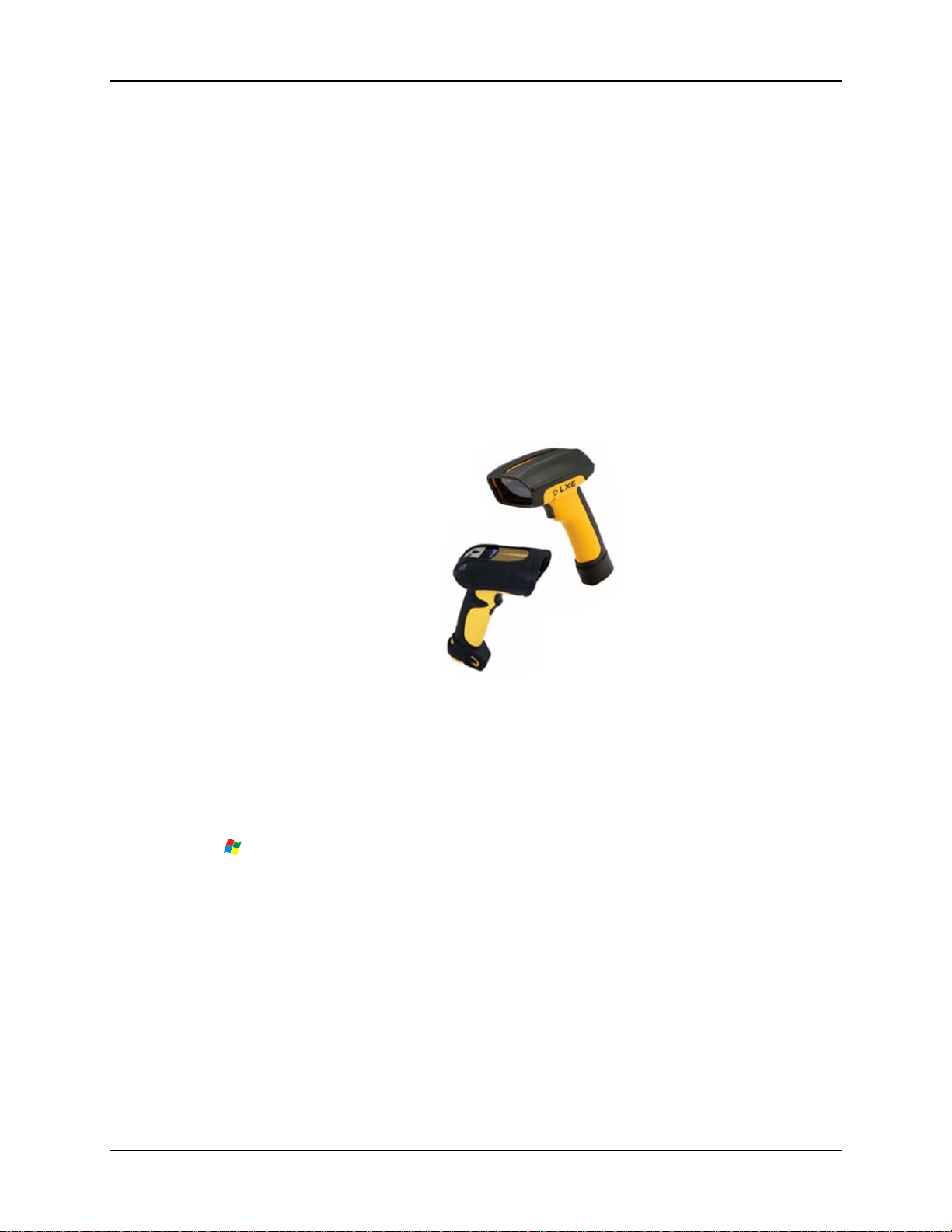
MX7 powered cradles support an accessory barcode label reading device. A tethered scanner can
be connected to the 9-pin RS-232 Serial Interface port on the front of the desktop cradle or to the
Serial Interface port on the back of the vehicle cradle.
MX7 keypad data entries can be mixed with tethered scanner barcode data entries. Any tethered
scanner that decodes the barcode internally and outputs an RS-232 data stream may be used. It
sends the data to the MX7 in ASCII format.
Figure 6 LXE Tethered Scanners (w/o cable)
LXE 8300 (Symbol) and 8500 (PowerScan) tethered scanners will send scanned data to the MX7
when the MX7 is in a powered cradle and the scanners are connected to the Serial Interface port
on the cradle. See “Accessories” for LXE approved tethered scanners for the MX7.
When a tethered scanner is connected to the Serial Interface port on a powered cradle, the MX7
must be configured as follows:
| Settings | Control Panel | Scanner | Main | either Port 1, Port 2 or Port 3
Select Port 2.
There is no software in the desktop or vehicle mount cradles. There is no software in the passive
vehicle mount cradle.
Bluetooth device connection and use, while the MX7 is docked, are managed by the MX7 Control
Panel Bluetooth program, not the cradle.
Note: The cradle must be powered by an external power source to enable tethered scanner use.
MX7 Cradle Reference Guide E-EQ-MX7DKRG-C
Page 13

Maintenance 7
Maintenance
There are no serviceable parts in the desktop or vehicle cradles. Do not attempt to open the units.
Desktop Cradles
Inspect the rubber feet and replace them if missing, broken or cracked. If the cradle is broken or
cracked, the cradle must be taken out of service and replaced. If the cradle is mounted to a flat
surface (i.e. desk, table, etc) examine the fasteners and re-tighten if necessary.
Contact LXE Customer Service (see Getting Help).
Vehicle Mounted Cradles
Check the vehicle bracket fasteners and re-tighten if necessary. If the vehicle bracket, cradle or
connections are broken, loose or cracked, the cradle must be taken out of service and replaced.
Contact LXE Customer Service (see Getting Help).
Cleaning
Do not use paper towels or harsh-chemical-based cleaning fluids since they may result in damage
to the surfaces and/or battery connectors.
Use a clean soft cloth to wipe any dirt, moisture or grease from the MX7, spare battery pack,
charging contacts or the cradle. Do not use any liquid to clean the cradle, battery pack, MX7, or
charging terminals (pins). If possible, clean only those areas which are soiled. Lint/particulates
can be removed from the connectors and charging pockets with clean, filtered canned air. If the tip
of the stylus is dirty, clean the tip with a water moistened cloth before touching the screen with the
stylus.
E-EQ-MX7DKRG-C MX7 Cradle Reference Guide
Page 14
8 Maintenance
MX7 Base Plate Replacement
The base plate, and the gasket underneath the base plate, on the MX7 may have to be upgraded
before the MX7 is docked in a cradle. In rare cases in which the MX7 will never be docked in an
MX7 cradle, the MX7 does not require a base plate upgrade.
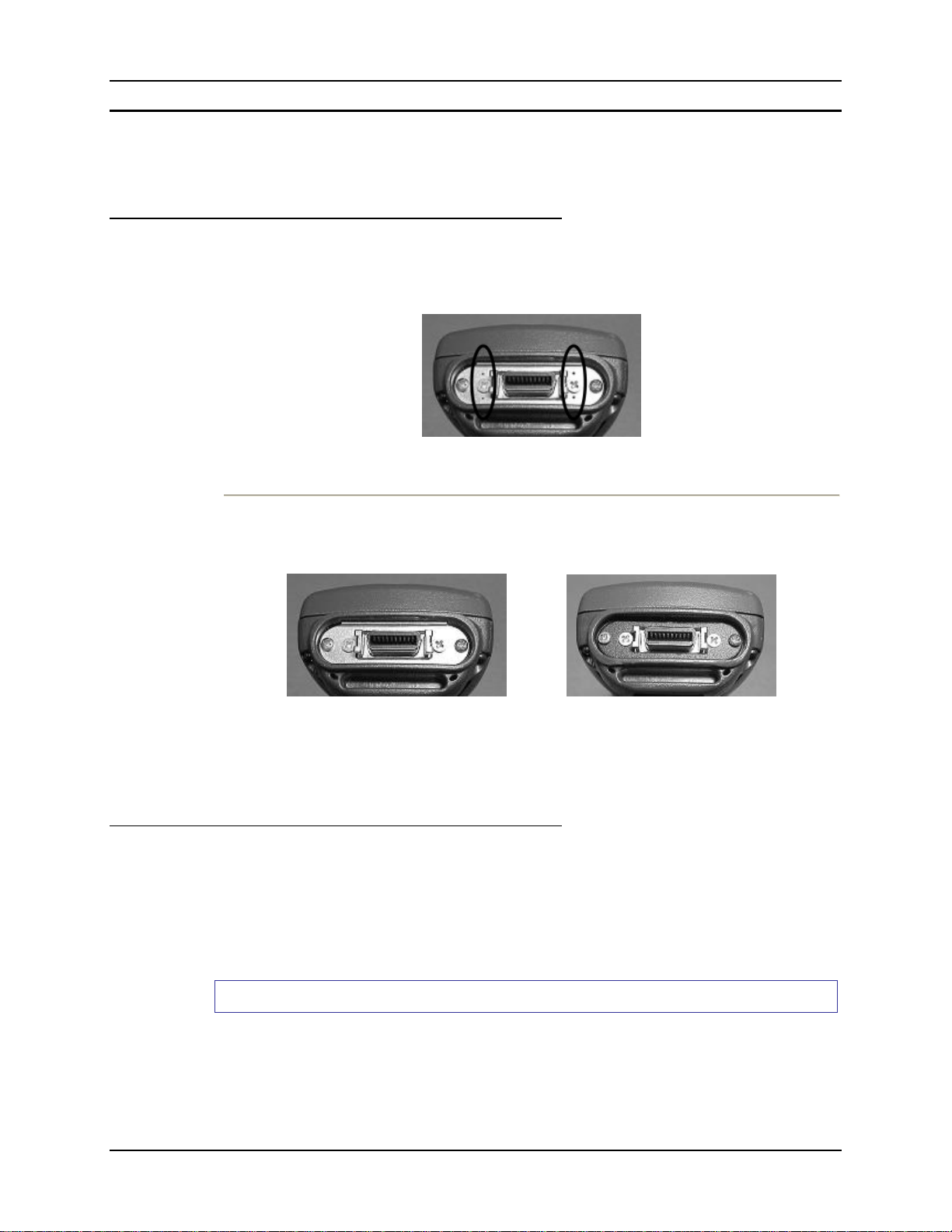
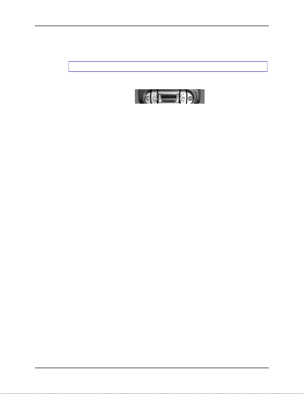
Identify Your MX7 Base Plate
If your MX7 has a stainless steel base plate with a pinhole above and below the screws next to the
input/output port, similar to the picture shown below:
Then the MX7 can be docked in a cradle without requiring the base plate upgrade.
If your MX7 has a base plate that looks like either of these two pictures (and without the
pinholes):
The base plate must be upgraded with the contents of this kit before the MX7 is placed in a cradle.
See Upgrade the Base Plate for instruction.
MX7 Base Plate Kit Part Number – MX7A586RPLCENDPLATE
Upgrade The Base Plate
Equipment Required: Phillips screwdriver (not supplied by LXE)
• You will need a torquing tool capable of torquing up to 2.5 in/lb
• LXE recommends the upgrade be performed on a clean, well-lit stable surface.
• Protect the MX7 internal components from static discharge.
• The base plate should not be replaced in a harsh, wet, or dirty environment.
Remove the Base Plate and Gasket
1. If the MX7 is On, place the MX7 in Suspend mode by quickly pressing and releasing the
Power button or by tapping Start | Suspend with the stylus on the touchscreen.
2. Using a phillips screwdriver, remove the four screws holding the base plate to the bottom of
the MX7. Set the screws aside in the order in which they were removed. Referring to the
photos on the previous page, the flat head screws are on either side of the input/output port
and the pan head screws are beside the plastic rim.
MX7 Cradle Reference Guide E-EQ-MX7DKRG-C
Page 15
Maintenance 9
3. Remove the base plate, and the gasket underneath the base plate, and set them aside. Note: Do
not use destructive force or move the input/output connector when removing the original base
plate.
Do not remove anything else from the base of the MX7.
Install the Upgrade
1. Place the gasket in the base plate opening.
2. Place the base plate on top of the gasket in the base plate opening.
3. The flat head screws are on either side of the input/output port and the pan head screws are
beside the plastic rim.
4. Using a torquing screwdriver, insert the screws in the correct screw holes, torquing each to
1.5 in/lb (0.168 n/M) to 2.5 in/lb (0.282 n/M).
The MX7 is ready for use.
Periodically check the connection of the base plate to the MX7 and re-torque if necessary.
E-EQ-MX7DKRG-C MX7 Cradle Reference Guide
Page 16
10 Getting Help
Getting Help
LXE user guides are now available on CD and they can also be viewed/downloaded from the LXE
ServicePass website. Contact your LXE representative to obtain the LXE Manuals CD or access
to the LXE ServicePass website. You can also check the LXE ServicePass website for the latest
manual releases.
Note: Obsolete/archived manuals are not available on the LXE Manuals CD. They are
available for download from the ServicePass website only.
You can get help from LXE by calling the telephone numbers listed on the LXE Manuals CD, in
the file titled Contacting LXE. This information is also available on the LXE website.
Explanations of terms and acronyms used in this guide are located in the file titled LXE Technical
Glossary on the LXE Manuals CD and on the LXE website.
Manuals
MX7 User’s Guide
MX7 Reference Guide
LXEbook – MX7 User’s Guide (can be downloaded to the MX7 device from the LXE Manuals
CD.)
MX7 Multi-charger User’s Guide
Accessories
Note: Items with a Green letter R in the second column are ROHS-compliant. Please contact your LXE
representative when ordering ROHS-compliant items as the part number may have changed. Items without
the letter R may have received ROHS-compliance after this guide was published. E designator means the
accessory is RoHS Exempt.
MX7 Cradle Accessories Part Numbers
Desktop Cradle Power Supply, AC/DC, US, with power cord
Desktop Cradle Power Supply, AC/DC, WW, without power
cord
Cradle, Desktop with spare battery charging
MX7 Passive vehicle cradle. Does not support charging or
communication. U-Bracket kit included.
RAM mount kit for MX7 Passive Vehicle Bracket. This kit
does NOT include the Cradle. Attaches to U-Bracket.
MX7 Active vehicle cradle. Supports charging and
communication.
MX7 Main Battery, Lithium Ion
Black rubber protective boot, designed for Desktop Cradle use.
Yellow rubber protective boot, designed for Desktop Cradle use.
MX7 Base Plate Kit
Power Supply (Vehicle Cradle)
Power Adapter, Bare Wire, 12VDC, 12 ft.
Cables (Cradle RS-232 or I/O Port connection only)
MX7 Charge/Comm Interface Cable, USB Client for
ActiveSync
9000A321PSACUS
R
9000A322PSACWW
R
MX7A388DESKCRADLEWW
R
MX7A007VMCRADLE
R
MX7A001RAMBRKT
R
MX7A008ACTIVEVMCRADLE
R
MX7A380BATT
R
MX7A490PROTBOOTBLK
R
MX7A491PROTBOOTYEL
R
MX7A586RPLCENDPLATE
R
9000A079CBL12ML3
R
MX7A052MULTICBLUSB
R
MX7 Cradle Reference Guide E-EQ-MX7DKRG-C
Page 17
Getting Help 11
MX7 Charge/Comm Interface Cable, RS-232 Serial ActiveSync,
D9 Female
RS-232 Serial Adapter Cable, 6 in., for use with printers that
provide their own source of power
MX7 Headset coiled adapter cable, includes quick disconnect
headset connector. A headset is still required.
MX7A055MULTICBLDA9F
R
MX7A058ADPTCBLPER
R
MX7A060ADPTCBLVOICE
R
Tethered Scanners (Cradle connection only)
Scanner, Powerscan SR, 8’ Cbl, WW
Scanner, Powerscan SR, 12’ Cbl, US
Scanner, Powerscan LR, 8’ Cbl, WW
Scanner, Powerscan LR, 12’ Cbl, US
Scanner, Powerscan XLR, 8’ Cbl, WW
Scanner, Powerscan XLR, 12’ Cbl, US
Scanner, LS3408ER, 9’ Cbl, US See Note
Scanner, LS3408FZ, Fuzzy Logic, 9’ Cbl, US. See Note
8300A326SCNRPWRSR8DA9F
R
8300A327SCNRPWRSR12DA9F
-
8310A326SCNRPWRLR8DA9F
R
8310A327SCNRPWRLR12DA9F
R
8320A326SCNRPWRXLR8DA9F
R
8320A327SCNRPWRXLR12DA9F
-
8520A326SCNRERDA9F
R
8510A326SCNRFZYDA9F
R
Note: When using the 8500 Series tethered scanners (LS3408), the tethered scanner Power Mode must be
set to “Reduced Power Mode” to conserve the device’s main battery life. The reduced power mode setting
will not impact performance of the 8500 series scanner. The default mode is “Continuous On”. Please refer
to the tethered scanner manufacturer’s user guide for instruction.
E-EQ-MX7DKRG-C MX7 Cradle Reference Guide
Page 18

12 Getting Help
MX7 Cradle Reference Guide E-EQ-MX7DKRG-C
Page 19

LXE recommends placing the desktop cradle on a stable, horizontal surface out of the way of:
• inclement weather conditions,
• extremely high concentrations of dust or wind blown debris,
• accidental knocks, bumps or other shocks to the MX7 and the cradle.
Allow clearance above the cradle for an MX7 with a trigger handle. Allow clearance behind the
cradle for power cable connection ease. Allow clearance in front of the cradle for serial and I/O
cable connect/disconnect ease.
Quick Start - Desktop Cradle
1. Refer to Install / Remove MX7 Desktop Cradle Adapter Cup.
2. Connect the cradle end of the power adapter cable to the Power port on the back of the cradle.
Refer to Cabling the Desktop Cradle.
3. Attach the AC power connector to a dependable power source. Refer to Cabling the Desktop
Cradle.
4. Attach any desired external cabled devices to the ports on the front of the cradle, if required.
Refer to Cabling the Desktop Cradle.
5. The desktop cradle is ready for use. Refer to Docking and Undocking the MX7 and
Insert/Remove a Spare Battery.
Desktop Cradle
Suggestions / Notes
• Remove cables from the base of the MX7 before inserting it in a cradle’s docking bay.
Refer to the MX7 User’s Guide for instruction.
• Route cradle cables to ensure they are protected from jostling, tugging or being
disconnected by items passing by.
• Remove the adapter cup from the powered cradle before docking an MX7 with a rubber
boot (MX7A490PROTBOOTBLK or MX7A491PROTBOOTYEL) installed.
• Use care when inserting the spare battery into the charging pocket. Do not slam the
battery into the pocket, this could damage the contacts at the base of the charging pocket.
• Keep dirt and foreign objects out of the cradle pockets. Do not short circuit any of the
contacts in the charging pockets, as this could result in injury or property damage.
E-EQ-MX7DKRG-C MX7 Cradle Reference Guide
Page 20
14 Components
Components
Front Back
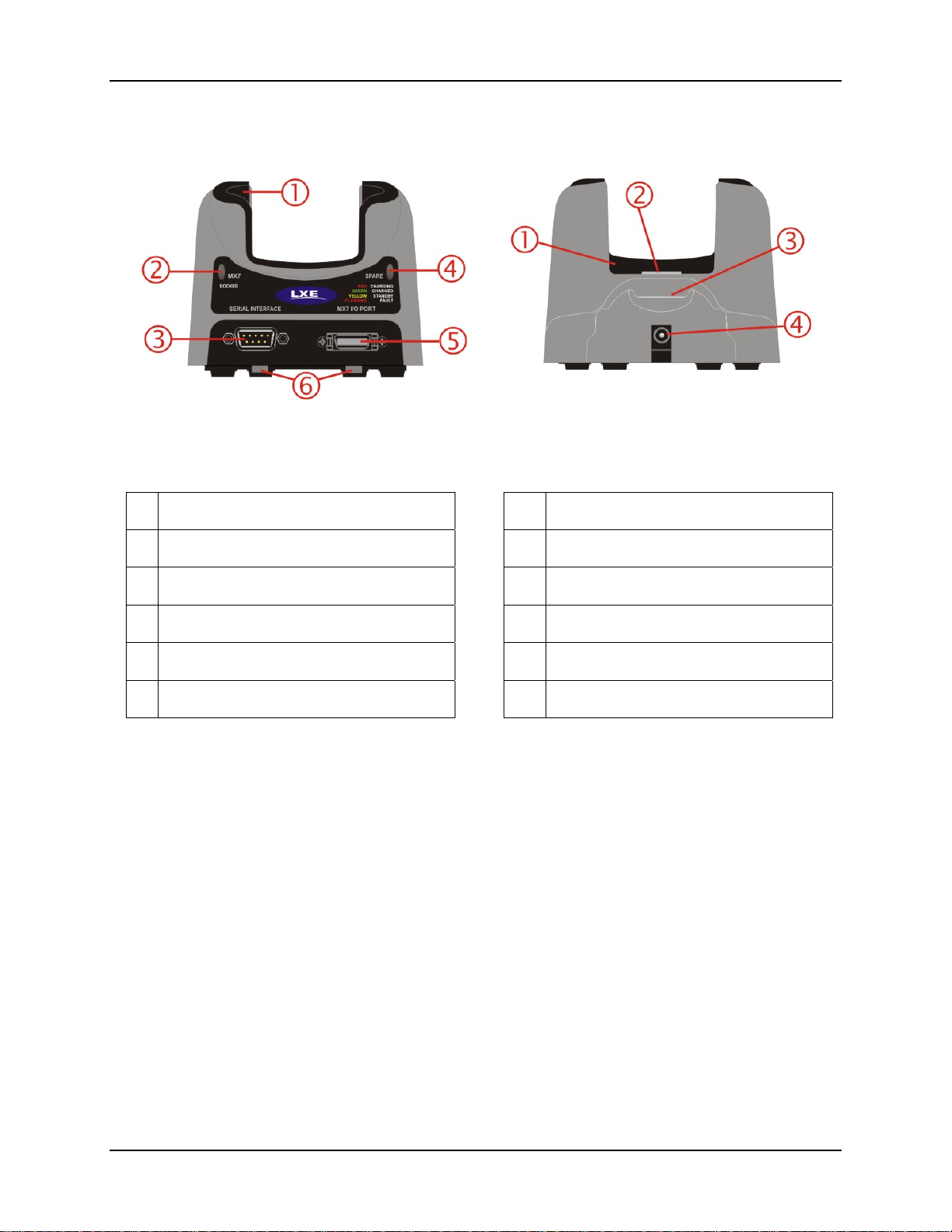
Figure 7 Desktop Components
1 Charging Pocket Adapter Cup 1 Charging Pocket Adapter Cup
2 MX7 Docked LED 2 MX7 Cradle Connector
3 Serial Interface Connector 3 Spare Battery Charging Bay
4 Spare Battery LED 4 Power Connector
5 I/O Connector
6 Table Mounting Hole Guides
MX7 Cradle Reference Guide E-EQ-MX7DKRG-C
Page 21
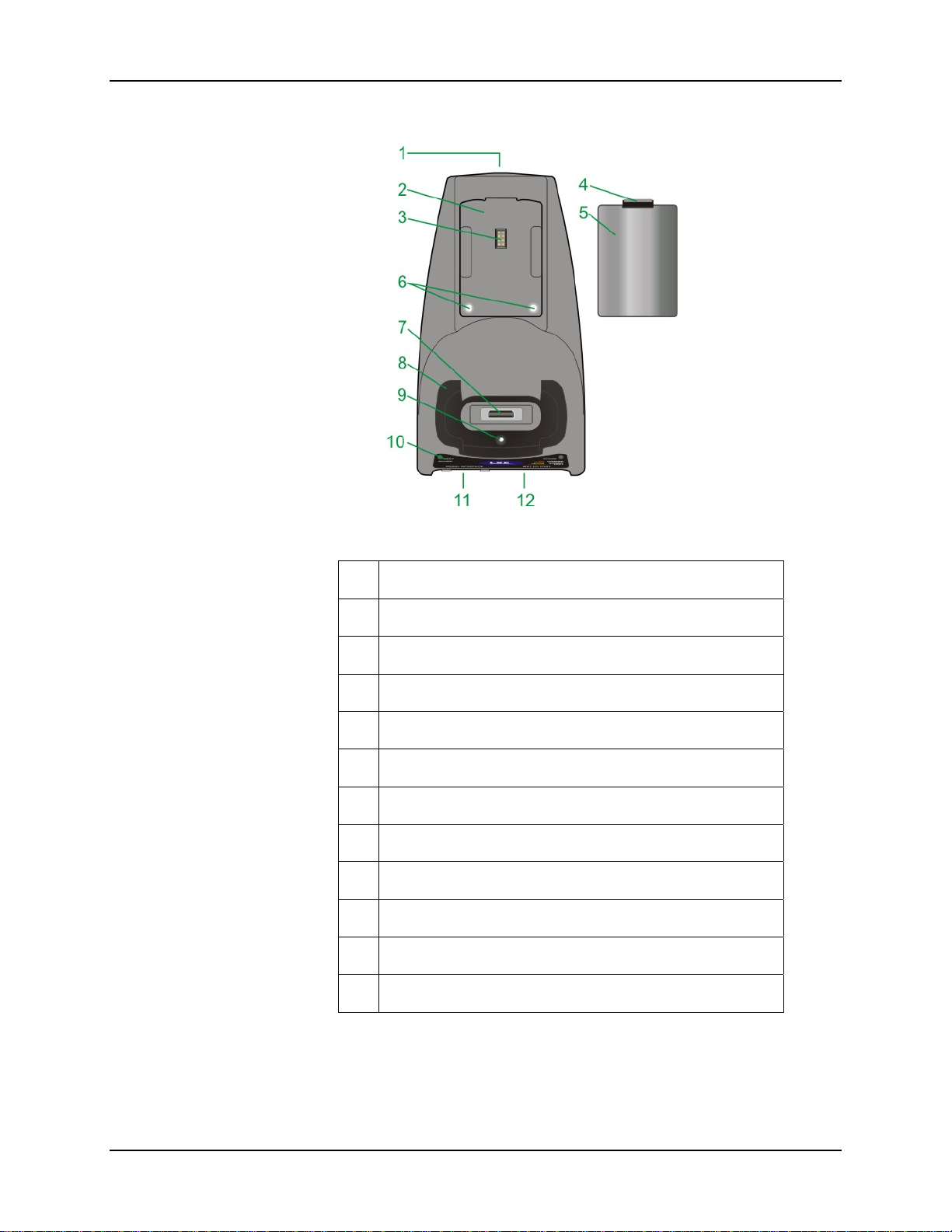
Components 15
Figure 8 Top
1. Power Supply Connector
2 Spare Battery Charging Bay
3 Spare Battery Charging Terminals
4 Spare Battery Latch
5 Spare Battery
6 Table Mounting Holes
7 MX7 Cradle Connector
8 MX7 Charging Pocket Adapter Cup
9 MX7 Charging Pocket Adapter Cup Mounting Hole
10 Desktop Cradle Label
11 MX7 Serial Interface Connector
12 MX7 I/O Connector
E-EQ-MX7DKRG-C MX7 Cradle Reference Guide
Page 22
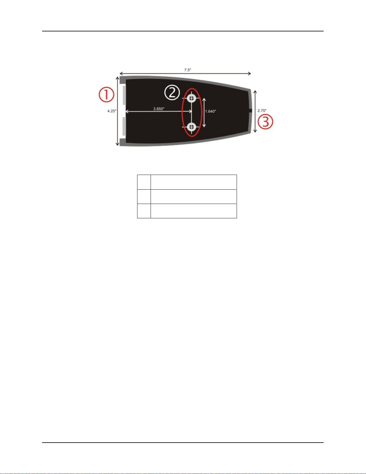
16 Desktop Mounting Footprint
Desktop Mounting Footprint
Figure 9 Table Mounting Hole Guides
1 Front
2 Table Mounting Hole Guides
3 Back
Bolts, washers, screws, screwdriver or wrench needed when attaching the desktop cradle to a
protected flat surface are not supplied by LXE. Periodically check the table mounting hardware
and re-tighten if necessary. Table mounting hardware can be finger-tightened.
Note: Do not over-tighten the table mounting hardware. If the cradle is cracked, it must be
replaced before being placed into service. Contact your LXE representative for
assistance.
Preparing the Desktop Cradle for Use
LXE recommends a stable, horizontal surface out of the way of:
• inclement weather,
• extremely high concentrations of dust or wind blown debris,
• accidental knocks, bumps or other shocks to the MX7 and the cradle, and
• enough space at cable connections to ensure cables are protected from jostling, tugging or
being disconnected by passing objects.
• See also MX7 Base Plate Replacement.
1. Position the cradle on a flat surface ensuring it is protected from unexpected events.
2. Fasten the cradle to a stable surface, if desired. See Desktop Mounting Footprint.
3. The desktop cradle is ready for use.
MX7 Cradle Reference Guide E-EQ-MX7DKRG-C
Page 23
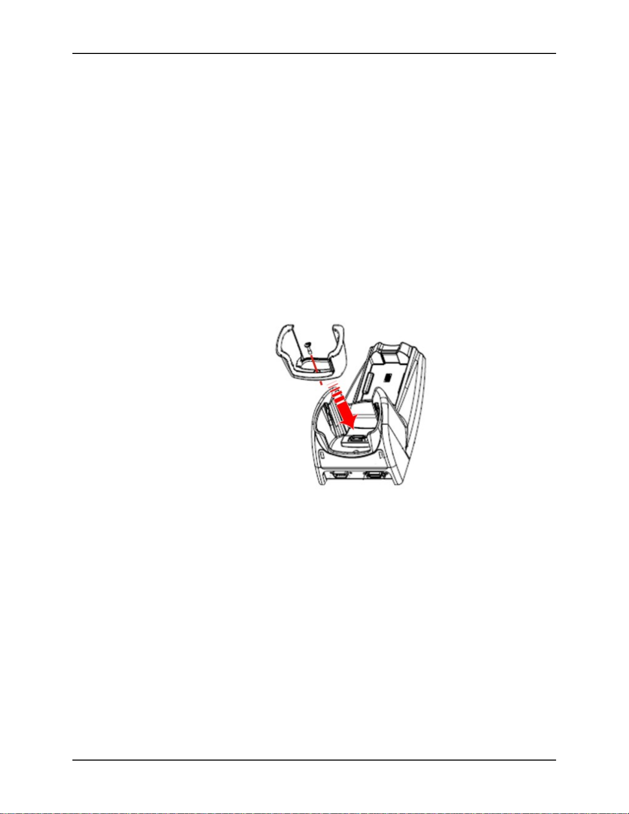
Install / Remove MX7 Desktop Cradle Adapter Cup 17
Install / Remove MX7 Desktop Cradle Adapter Cup
Equipment Required -- Phillips screwdriver and torquing tool (not supplied by LXE). You will
need a torquing tool capable of torquing up to 6 (+/- .5) in/lb. LXE recommends using a clean,
well-lit stable surface.
The desktop cradle is shipped with the cradle adapter cup pre-installed.
The MX7 charging pocket, without a cradle adapter cup, is designed for an MX7 with a rubber
(MX7A490PROTBOOTBLK or MX7A491PROTBOOTYEL) enclosing/protecting the mobile
boot
device.
Before docking an MX7 without a rubber boot in the cradle, re-install the MX7 adapter cup.
Install -- The adapter cup is installed facing in one direction. Put the adapter cup in the MX7
charging pocket, aligning the screw hole in the adapter cup with the screw hole in the MX7
charging bay. Using a torquing screwdriver, insert the screw in the adapter cup screw hole, and
torque the screw to 6 in/lbs +/- .5 in/lbs.
Periodically check the connection of the adapter cup and re-torque if necessary.
Figure 10 MX7 Charging Pocket Adapter Cup
Remove -- Remove the adapter cup by unscrewing the single captive screw at the front of the
adapter cup. Place both the adapter cup and the screw in a protected, safe place until needed.
E-EQ-MX7DKRG-C MX7 Cradle Reference Guide
Page 24
18 Cabling the Desktop Cradle
Cabling the Desktop Cradle
Note: Route all cables to ensure they are protected from jostling, tugging or being
disconnected by passing objects.
The cradle must be receiving power from an external power source before battery charging can
begin.
Assemble/Attach the AC Power Adapter
The LXE-approved AC Power Adapter is only intended for use in a 25°C (77°F) maximum
ambient temperature environment.
Note: Connect the cable to the cradle first, then to an AC source.
If the AC power cable is not included with the AC Adapter, please contact your LXE
representative for assistance.
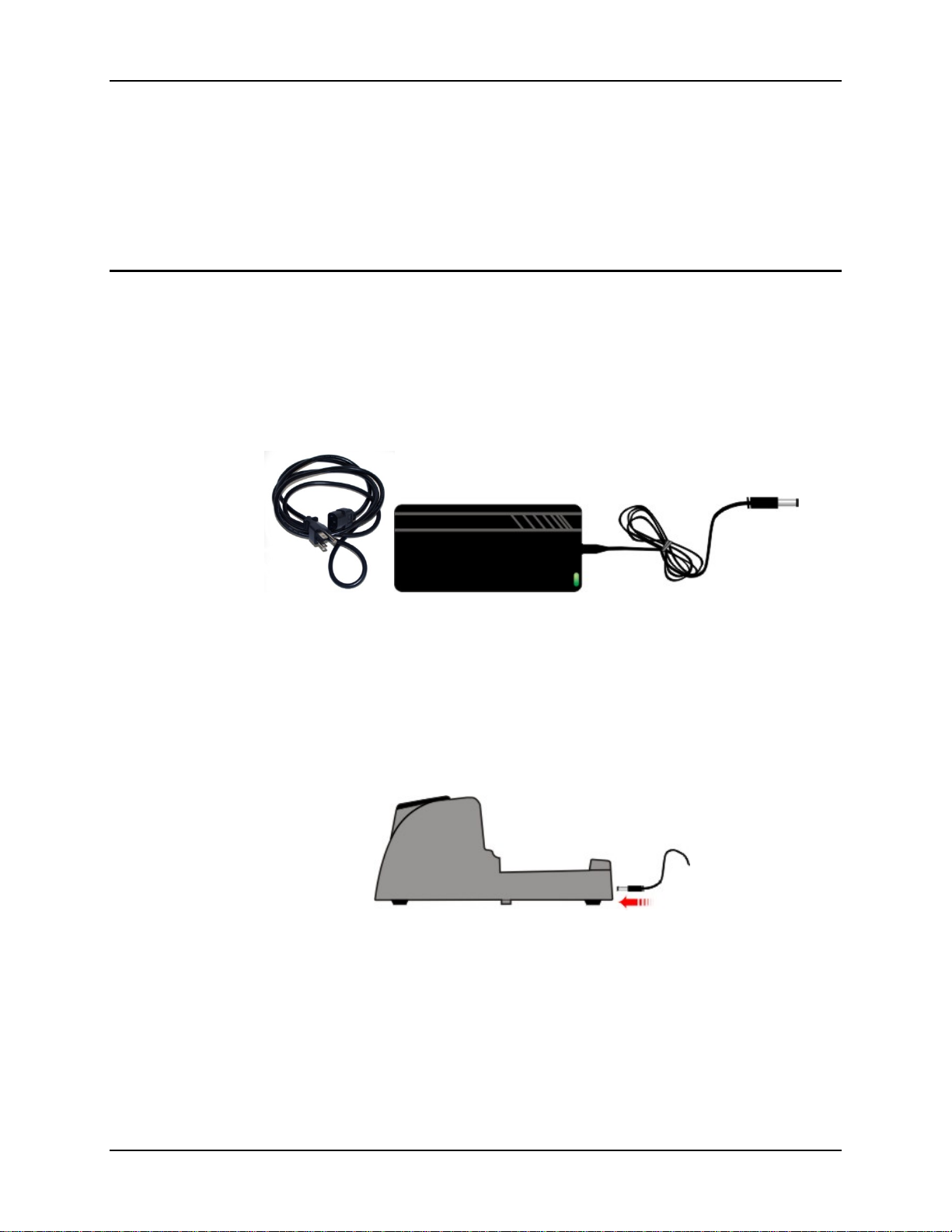
Figure 11 AC/DC 12V External Power Supply and 3-prong Cable
Firmly press the cradle end of the power cable into the female connector on the back of the
cradle.
Firmly press the female end of the power cable into the male connector on the power adapter.
Plug the 3-prong cable into any AC wall outlet with a dependable power source.
AC power is now being supplied to the AC/DC power adapter and the cradle.
Figure 12 Connect Power Cable to the Cradle
MX7 Cradle Reference Guide E-EQ-MX7DKRG-C
Page 25
Cabling the Desktop Cradle 19
Attach a Serial or I/O Connector
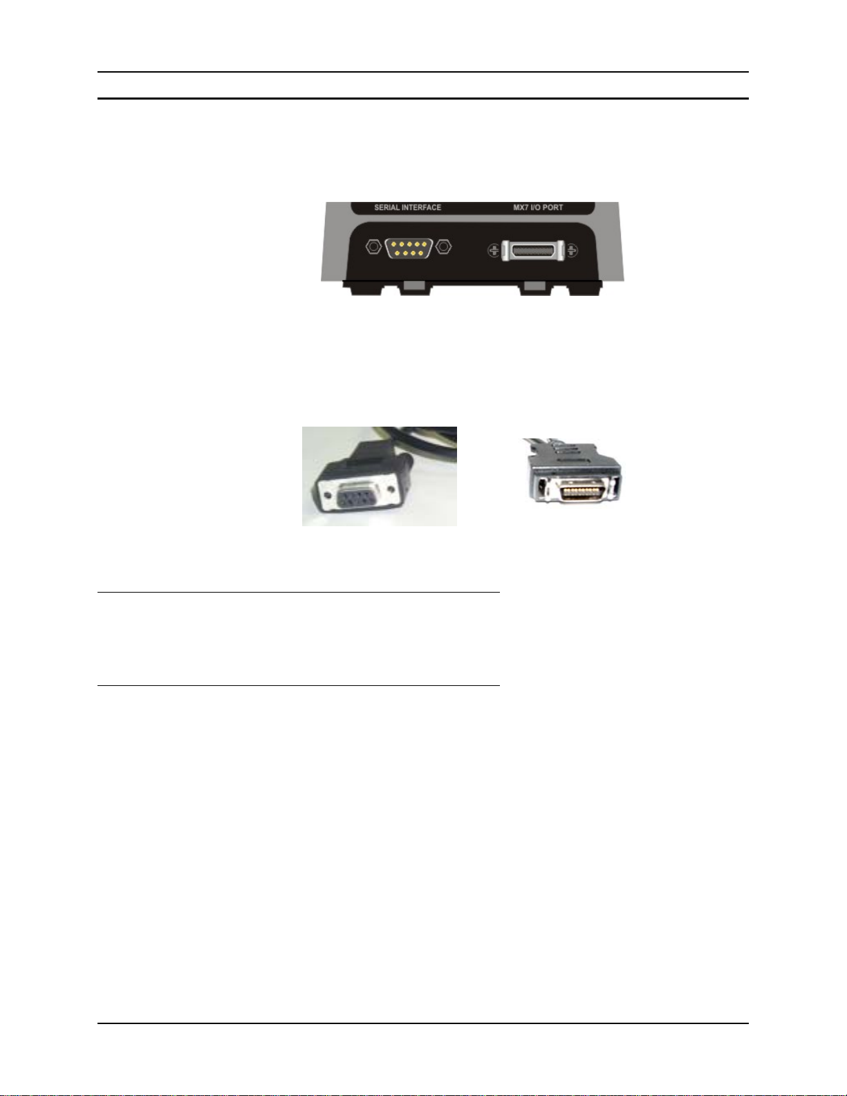
The serial cable is connected to the port labelled Serial Interface on the left front of the desktop
cradle. The serial cable end can originate with a tethered scanner, a desktop/laptop PC, a printer or
another serial device.
Figure 13 Serial Connector and I/O Connector
The I/O connector cable is connected to the port (male) labelled MX7 I/O Port on the right front
of the desktop cradle.
Serial Cable End MX7 I/O Cable End
Serial Cable
I/O Cable
Periodically test the connections for stability and re-tighten if necessary.
Align the RS-232 serial cable end (female) carefully to the Serial Interface port (male) on the left
front of the desktop cradle. Press the ends together and finger tighten the screws on either side of
the connector. Test the connection for stability.
Squeeze the clips next to the connector attached to the cable to open the catches in the connector
assembly. Firmly press the cable end (female) into the MX7 I/O Port connector (male) on the
front of the cradle. Release the clips in the connector cable. Test the connection for stability.
E-EQ-MX7DKRG-C MX7 Cradle Reference Guide
Page 26
20 Cabling the Desktop Cradle
Pinout - RS-232 Connector
Note: Tethered scanners must be connected to powered cradles.
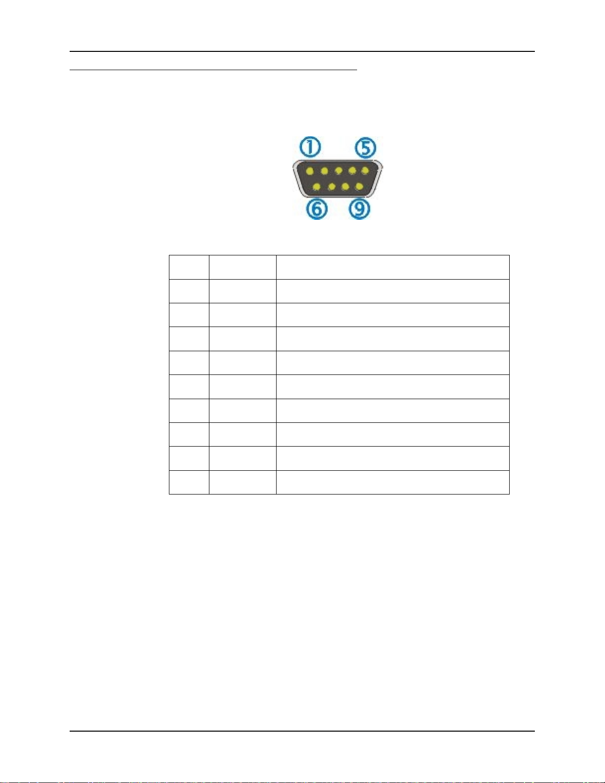
The connector is industry-standard RS-232 and is a PC/AT standard 9-pin D male connector.
Figure 14 Desktop Cradle RS-232 and Pinout
Pin Signal Description
1 DCD Data Carrier Detect
2 RXD Received Data – Input
3 TXD Transmitted Data – Output
4 DTR Data Terminal Ready
5 GND Signal/Power Ground
6 DSR Data Set Ready
7 RTS Request to Send
8 CTS Clear To Send
9 RI or Power +5 VDC sourced by the Cradle
Note: Pin 9 of this port is connected to +5 VDC and only approved LXE cables are to be used
for communication between the cradle and external devices.
MX7 Cradle Reference Guide E-EQ-MX7DKRG-C
Page 27

Docking and Undocking the MX7 21
Docking and Undocking the MX7
Refer to previous section titled Install / Remove MX7 Desktop Cradle Adapter Cup.
When the MX7 is in Suspend Mode it wakes up when docked in a powered cradle. There is no
change in mode state settings or behavior when the MX7 is docked in an unpowered cradle.
MX7 mode states while the MX7 is in a powered cradle e.g. suspend, resume, display backlight,
etc., are managed by the settings in Start | Settings | Control Panel | Power and Start | Settings
| Control Panel | Display.
If the cradle is not permanently attached to the work surface, remember to stabilize the cradle
with one hand while inserting or removing the MX7 with the other hand.
The MX7 is inserted into the charging pocket with the keypad facing forward.
Dock the MX7 -- Carefully press the MX7 down into the charging pocket until the 20 pin
connector at the base of the MX7 clicks into place with the charging connector at the bottom of
the charging well. The Docked LED illuminates.
Undock the MX7 -- Remove the MX7 from the cradle by pulling it straight up and out of the
charging pocket. The Docked LED turns Off.
Battery Charging in a Desktop Cradle
• The MX7 main battery recharging is managed by the Power Management settings in the
MX7. Refer to Start | Settings | Control Panel | Power on the MX7.
• The spare battery re-charges with or without an MX7 in the dock. The spare battery is
fully charged in approximately four hours.
• The cradle must be receiving power from an external power source before MX7 battery or
spare battery pack charging can take place.
Technical Specifications – Desktop Cradle
Note: Do not store MX7 batteries above 140°F (60°C) for extended periods.
Weight 18 oz / 500 grams
Dimensions H 3.5 in x W 4.25 in x L 7.5 in
Temperature
Operating 32° F to 104° F / 0° C to 40° C (Charger is receiving AC/DC power)
Charging 50° F to 104° F / 10° C to 40° C (Charging cups are occupied)
Storage -4° F to 158° F / -20° C to 70° C (No AC/DC power)
Humidity 5% to 90% (non-condensing) at 104° F / 40° C
IEC 60529 Compliant to IP40
Ports Power and serial ports
E-EQ-MX7DKRG-C MX7 Cradle Reference Guide
Page 28
22 Insert / Remove a Spare Battery
Insert / Remove a Spare Battery
Pre-requisites: The steps outlined in Assemble/Attach the AC Power Adapter have been
completed and the cradle has a dependable power source. The cradle has been
bolted to a stable surface, if required.
Note: Do not drop or slam the spare battery into the charging bay. Damage may result.
A fully depleted spare battery recharges in approximately four hours in the MX7 powered cradle.
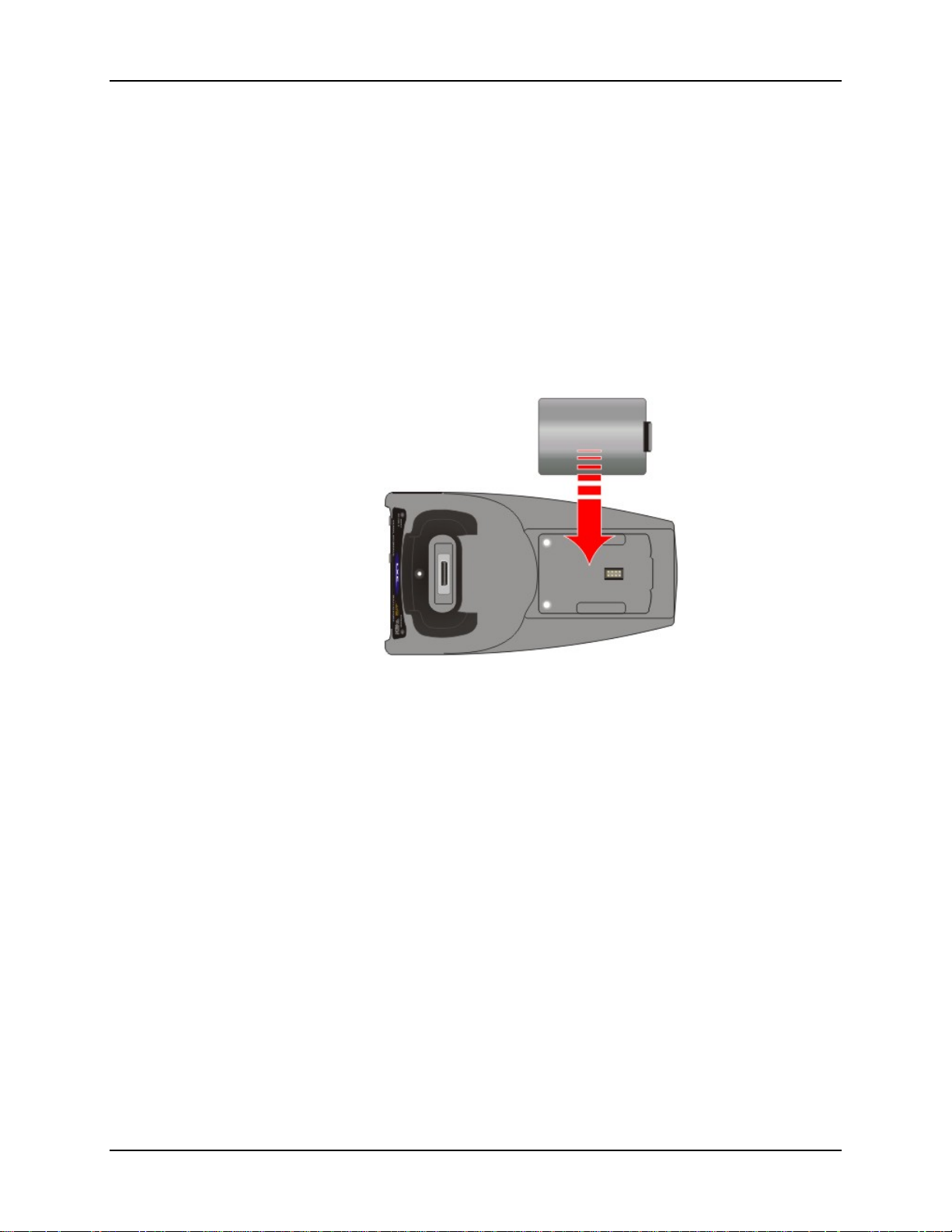
The spare battery well is molded in the shape of the MX7 main battery. The spare battery can be
inserted in the battery well in only one direction.
When there is an MX7, with or without a handle, docked in the cradle, a spare battery can still be
inserted in the charging bay. You do not need to undock the MX7.
Figure 15 Spare Battery Charging Bay
Insert -- Tilt the end (without the latch) of the spare battery pack into the upper end of the battery
charging well, and firmly press the other end (with the latch) until the battery is fully inserted into
the battery well.
Push down on the battery pack until it clicks into place. This will ensure the charging contacts on
the spare battery connect with the charging contacts in the battery well. The Spare charging bay
LED illuminates.
Remove -- Remove the charged battery by pressing the latch in and pulling the battery up with a
hinging motion and out of the charging bay. The Spare charging bay LED turns Off.
A green spare battery LED signifies the spare battery is fully charged.
MX7 Cradle Reference Guide E-EQ-MX7DKRG-C
Page 29

Introduction
Powered Vehicle Mount Cradle
This cradle is specifically designed for vehicle mounting. The cradle restrains the MX7 with or
without a boot, handle or strap. Cables must be removed from the base of the MX7 before it is
placed in the vehicle cradle pocket. Overhead, dash and roof support pillar mounting is via a
RAM Mount accessory which includes all the hardware and squeeze plates required for vehicle
mounting. Multiple attachment points for the RAM ball mechanism are located on the back of the
vehicle cradle.
The MX7 is inserted into the cradle by placing the base of the MX7 in the cradle pocket and
firmly pressing the unit backward until the Retainer latches catch on the front of the MX7,
securing it in the charging pocket.
The MX7 is removed from the vehicle cradle by pushing the front of the Retainer up and back
until the MX7 is released from the Retainer latches and the charging pocket swings forward. Pull
the MX7 up and out of the cradle pocket.
The vehicle mounted cradle should be mounted in an area in the vehicle where it:
• Does not obstruct the driver's vision or safe vehicle operation.
• Will be protected from rain or inclement weather.
• Will be protected from extremely high concentrations of dust or wind-blown debris.
• Can be easily accessed by a user seated in the driver's seat while the vehicle is not in
operation.
Before installation begins, verify you have the applicable vehicle mounting assembly components
necessary for your mount type, as shown in the next section titled “Components”.
Do not put the MX7 into the cradle pocket until the cradle is securely fastened to the vehicle.
Do not slam the MX7 into the cradle pocket. Damage to the cradle and MX7 components
may occur. Always put the handle through the Handle Opening first or damage to the
scanner aperture may occur. If the cradle or MX7 is damaged, it must be removed from
service and repaired before placing it into service again.
E-EQ-MX7DKRG-C MX7 Cradle Reference Guide
Page 30
24 Quick Start - Powered Vehicle Cradle
Quick Start - Powered Vehicle Cradle
1. Attach the RAM bracket mounting device to the vehicle.
2. Attach the MX7 vehicle cradle to the RAM bracket.
3. Attach a tethered scanner connector to the serial port on the back of the cradle, if required.
Tethered scanners must be connected to powered vehicle cradles.
4. Attach the DC/DC or 12VDC power connector from the vehicle mounted power supply to the
Power port on the back of the cradle.
5. Secure all cables to the vehicle cradle using the cable clamps.
6. The Vehicle Mount cradle is ready for use.
For installation instructions, see Powered Vehicle Cradle Mounting later in this guide.
Components
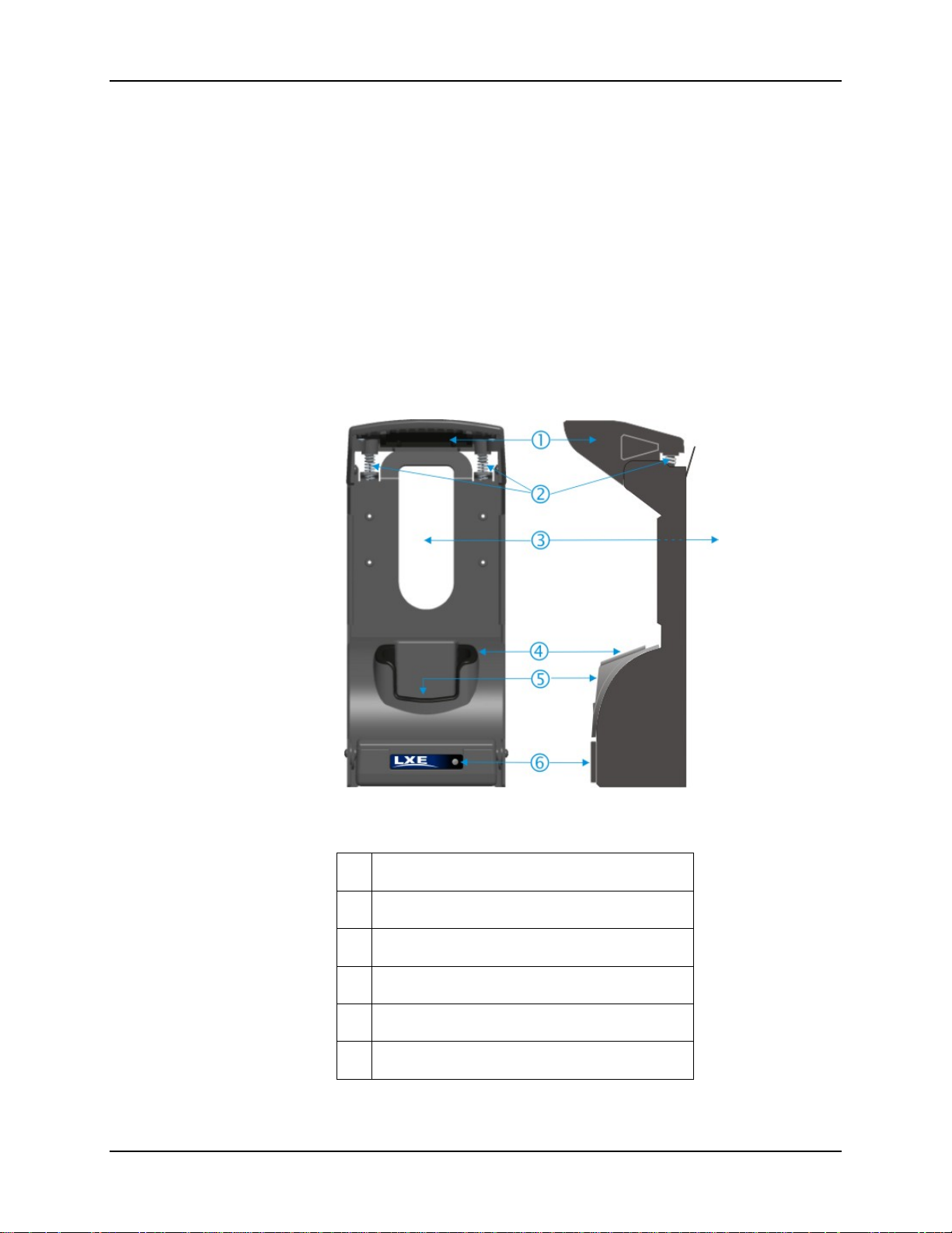
Figure 16 Vehicle Mount Cradle – Front
1 Retainer
2 Retainer Springs
3 Handle Opening
4 Vehicle Cradle Adapter Cup
5 Charging Pocket
6 MX7 Docked LED
MX7 Cradle Reference Guide E-EQ-MX7DKRG-C
Page 31
Components 25
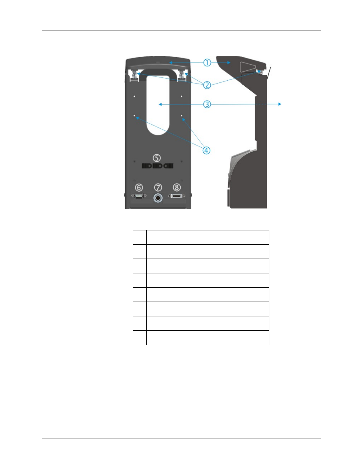
Figure 17 Vehicle Mount Cradle – Back
1 Retainer
2 Retainer Springs
3 Handle Opening
4 RAM Bracket Mounting Locations
5 Strain Relief Cable Clamps
6 Serial Interface Port
7 Power Connector
8 MX7 I/O Port
E-EQ-MX7DKRG-C MX7 Cradle Reference Guide
Page 32
26 Install / Remove Vehicle Cradle Adapter Cup and Top Adapter
Install / Remove Vehicle Cradle Adapter Cup and Top Adapter
Equipment Required -- Phillips screwdriver and torquing tool (not supplied by LXE). You will
need a torquing tool capable of torquing up to 6 in/lb (+/- .5 in/lb) for the cradle adapter cup.
LXE recommends using a clean, well-lit stable surface.
The vehicle cradle is shipped with the cradle adapter cup and Retainer Insert pre-installed.
The MX7 cradle charging pocket, without a cradle adapter cup and top adapter, is designed for an
MX7 with a rubber boot (MX7A490PROTBOOTBLK or MX7A491PROTBOOTYEL)
enclosing/protecting the mobile device.
Before docking an MX7 without a rubber boot in the vehicle cradle, re-install the MX7 adapter
cup and Retainer Cap Insert.
Install Adapter Assembly
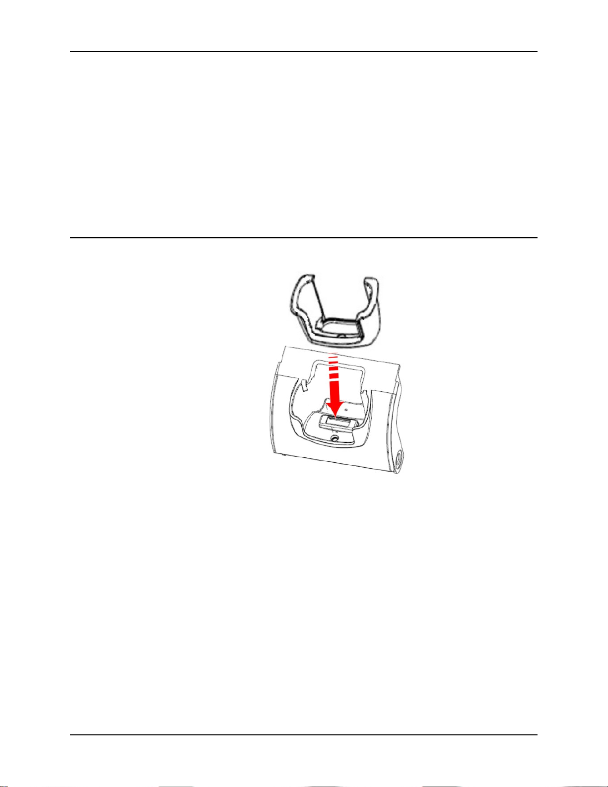
Figure 18 Charging Pocket Adapter Cup
The adapter cup is installed facing in one direction.
1. Slip the adapter cup into the cradle charging pocket, aligning the screw hole in the adapter
cup with the screw hole in the charging bay.
2. Using a torquing screwdriver, insert the screw in the adapter cup screw hole, and torque the
screw to 6 in/lbs +/- .5 in/lbs.
MX7 Cradle Reference Guide E-EQ-MX7DKRG-C
Page 33
Install / Remove Vehicle Cradle Adapter Cup and Top Adapter 27
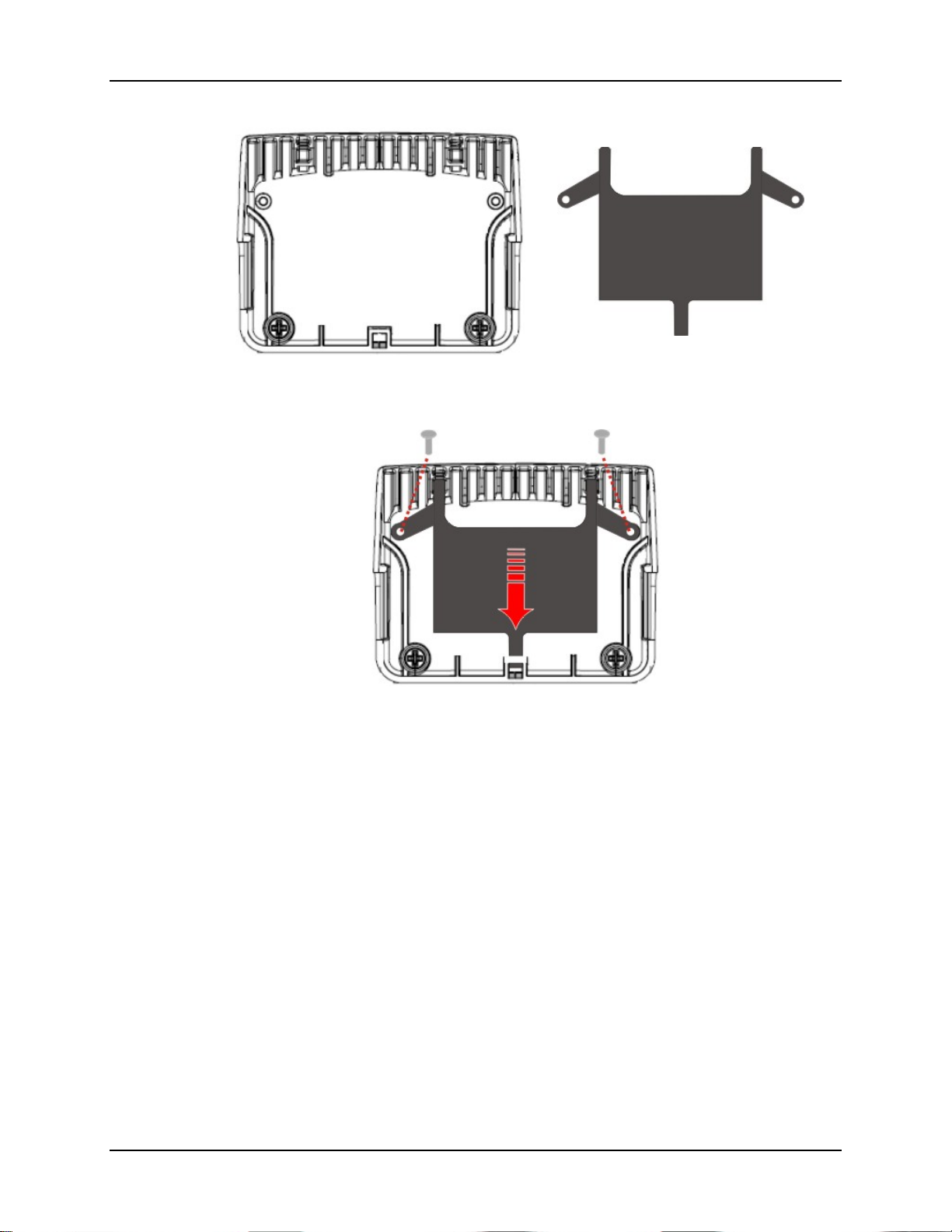
Underside of Retainer Cap Retainer Cap Insert
Assembled
Figure 19 Retainer Insert
The Retainer insert has three tabs.
1. Lay the flat side of the Insert against the underside of the Retainer cap.
2. The Insert back tab slides into the slot at the back of the Retainer.
3. The Insert is fastened to the Retainer cap using screws and the pre-drilled holes in the angled
tabs (one on each side).
4. The Insert is secured in place with two screws (the screws do not require a torquing tool).
Periodically check the connection of the adapter cup and re-torque if necessary. Periodically
check the Retainer Insert connection and re-tighten if necessary.
E-EQ-MX7DKRG-C MX7 Cradle Reference Guide
Page 34
28 Install / Remove Vehicle Cradle Adapter Cup and Top Adapter
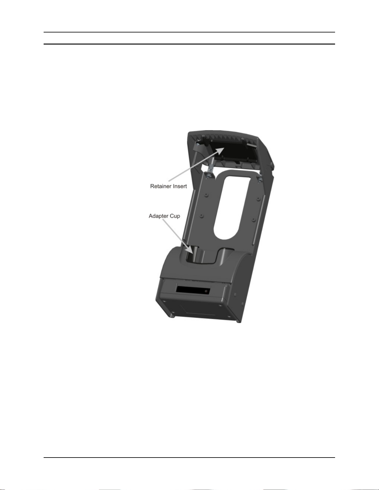
Remove Adapter Assembly
1. Remove the adapter cup by unscrewing the single captive screw at the front of the adapter
cup.
2. Remove the Retainer Cap Insert by unscrewing the two screws holding it to the Retainer.
Slide the tab out of the slot in the back of the Retainer assembly.
3. Place the screws, adapter cups and the Retainer Cap Insert in a protected, safe place until
needed.
If the adapter cup or retainer insert are cracked or broken, they must be replaced before a powered
vehicle cradle, with an adapter cup and Retainer Cap Insert, is placed into service.
Figure 20 Adapter Assembly
MX7 Cradle Reference Guide E-EQ-MX7DKRG-C
Page 35
Docking and Undocking the MX7 29
Docking and Undocking the MX7
Refer to previous section titled Install / Remove Vehicle Cradle Adapter Cup and Top Adapter.
When the MX7 is in Suspend Mode it wakes up when docked in a powered cradle. There is no
change in mode state settings or behavior when the MX7 is docked in an unpowered cradle.
MX7 mode states while the MX7 is in a powered cradle e.g. suspend, resume, display backlight,
etc., are managed by the settings in Start | Settings | Control Panel | Power and Start | Settings
| Control Panel | Display in the MX7 Control Panel.
The MX7 can be inserted and removed from the charging pocket with one hand.
The MX7 is inserted into the charging pocket with the keypad facing forward. Always put the
handle through the Handle Opening first or damage to the scanner aperture may occur.
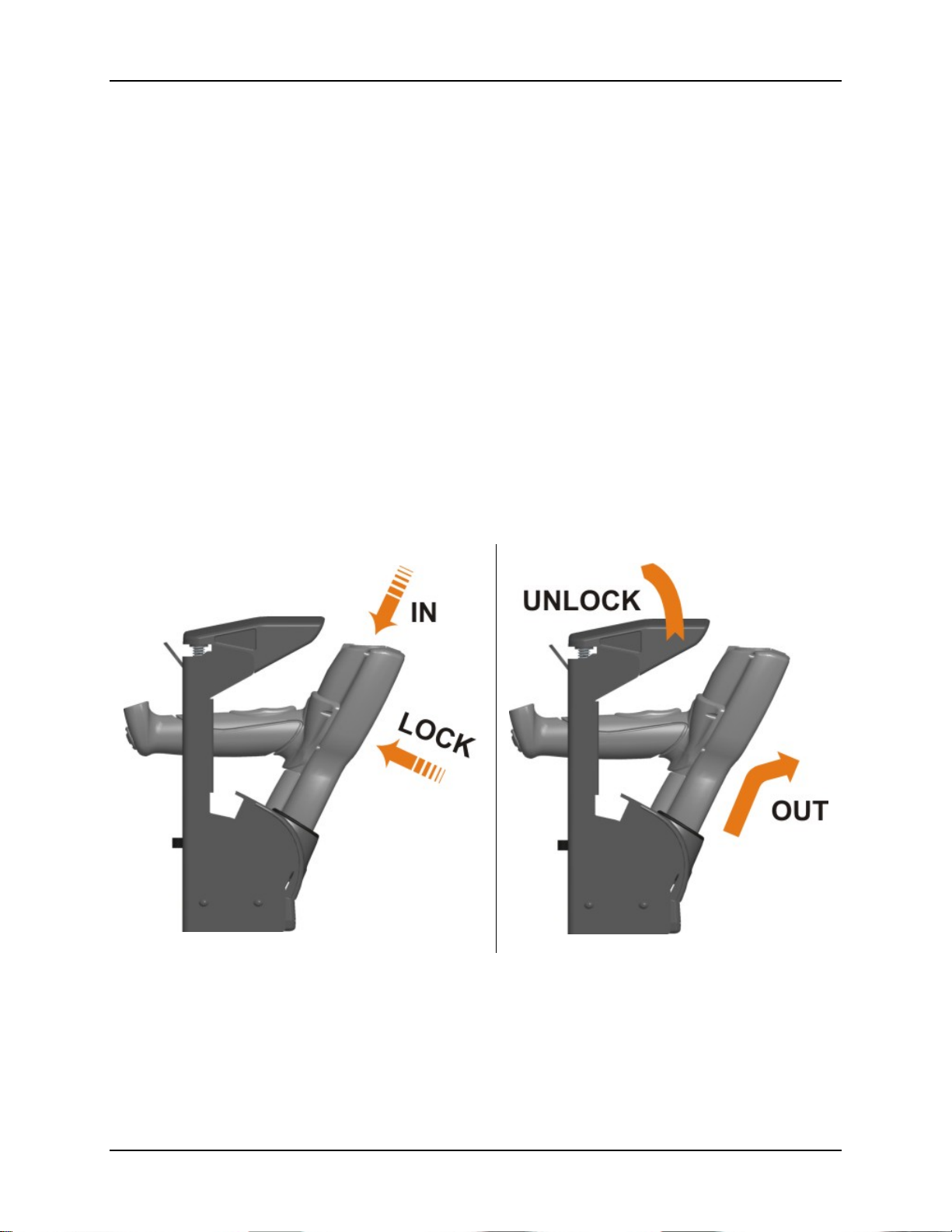
Dock the MX7 -- Carefully press the MX7 down into the charging pocket until the 20 pin
connector at the base of the MX7 clicks into place with the charging connector at the bottom of
the charging well. The Docked LED illuminates.
Push the MX7 backwards into the vehicle cradle until the Retainer snaps forward, securing the
MX7 to the vehicle cradle.
Undock the MX7 -- Remove the MX7 from the cradle by first lifting the Retainer upwards. The
MX7 charging pocket hinges forward, allowing the MX7 to be pulled up and out of the charging
pocket. The Docked LED turns off.
Figure 21 MX7 Docking and Undocking
Important: Do not dock the MX7 until the dock is secured a nd stable. If the cradle or MX7 is
damaged, it must be removed from service and repaired.
E-EQ-MX7DKRG-C MX7 Cradle Reference Guide
Page 36
30 RAM Bracket Mounting
RAM Bracket Mounting
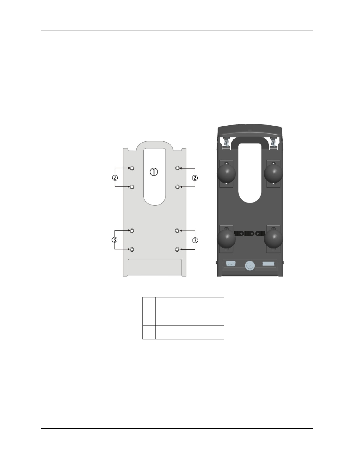
RAM Bracket Assembly mounting holes are on the back of the cradle. The mounting screws fit in
Pim nuts and are automatically secured.
The number of RAM balls attached to the back of the vehicle mount cradle are dependent upon
the desired RAM mount configuration. The figure shown below is for demonstration purposes
only.
RAM ball mounting screws are included in the mounting kit. Contact your LXE representative for
assistance, if needed.
Figure 22 RAM Bracket Mounting Points – Cradle Back
1 Trigger Handle opening
2 Upper mounting points
3 Lower mounting points
MX7 Cradle Reference Guide E-EQ-MX7DKRG-C
Page 37
RAM Bracket Mounting 31
RAM Circular Base Footprint
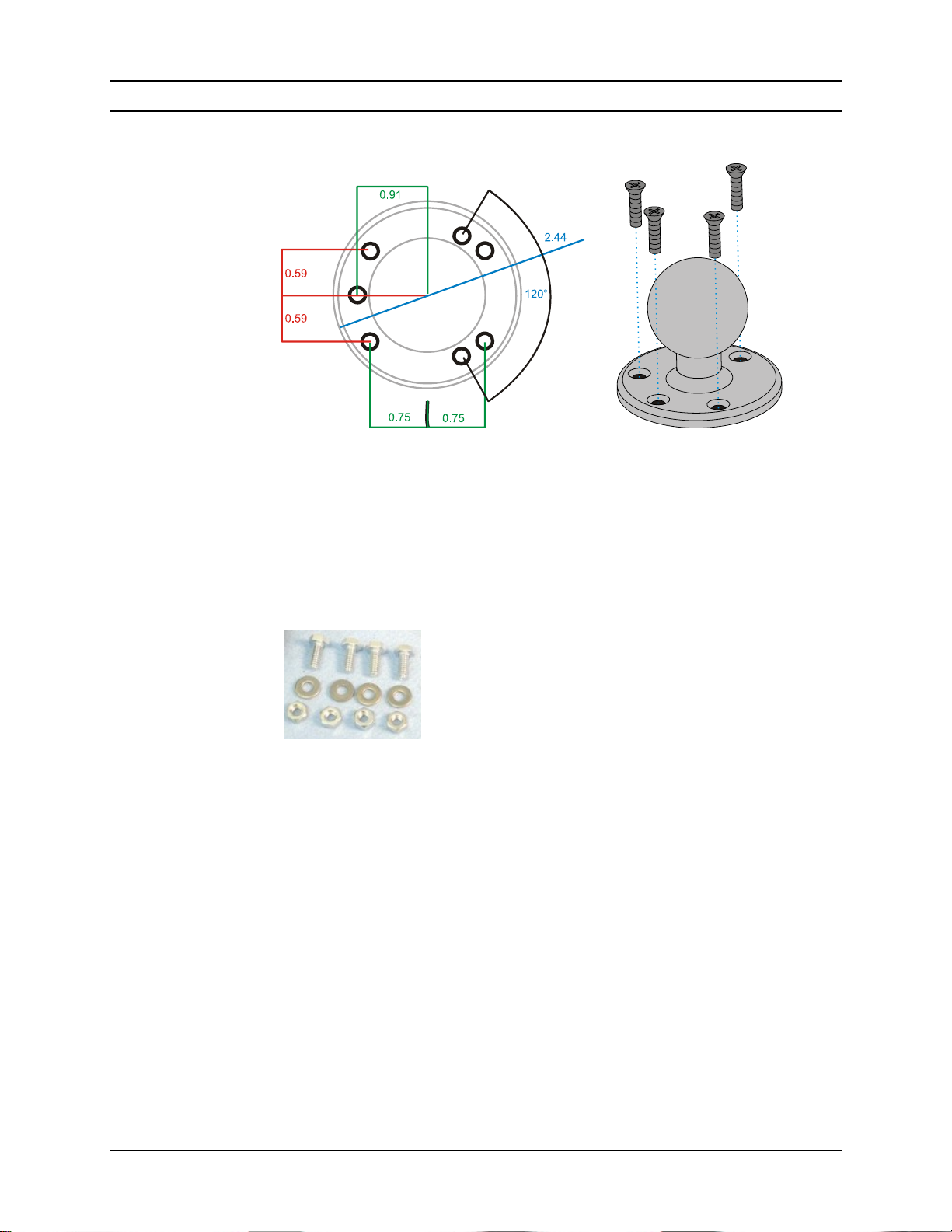
Not To Scale
Figure 23 RAM Base Dimensions
Note: LXE does not supply the bolts or washers needed when mounting the cradle assembly to
the vehicle chassis. LXE recommends using bolts with a maximum 10/32” (0.3125)
diameter.
Bolts, washers and nuts for mounting the RAM ball to
the vehicle are supplied by LXE.
Qty 4 – Hex Cap ¼-20 x ¾ bolts
Qty 4 – ¼ flat washer
Qty 4 – 1/4-20 nylon insert lock nuts
E-EQ-MX7DKRG-C MX7 Cradle Reference Guide
Page 38
32 Vehicle Cradle RAM Ball Assembly
Vehicle Cradle RAM Ball Assembly
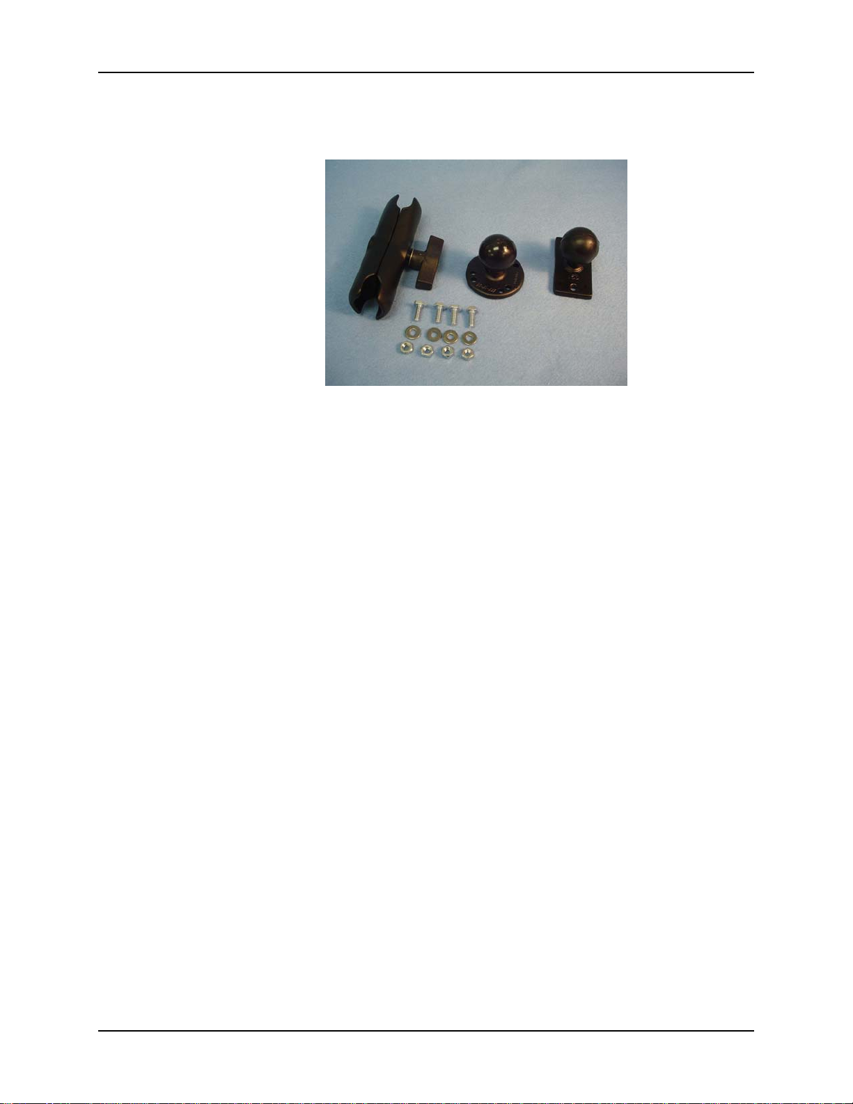
Figure 24 RAM Bracket Components
• There must be enough clearance at the back of the cradle to accept an MX7 with an
installed trigger handle.
• There must be at least 2” clearance at the back of the vehicle cradle for power, serial
interface and MX7 I/O Port cables
• There must be enough clearance to accept an MX7 with an installed trigger handle.
• Position the bracket to allow access to the ports on the back of the Vehicle Mount Cradle.
1. Fasten the RAM ball with the circular mounting base to the vehicle.
2. Fasten the RAM ball with the rectangular mounting base to the back of the vehicle cradle.
3. Loosen the knob on the squeeze arm.
4. Place either RAM ball opening over the vehicle mounted RAM ball.
5. Place the remaining RAM ball opening over the vehicle cradle mounted RAM ball.
6. Tighten the knob on the squeeze arm until the vehicle cradle is secured to the vehicle.
Adjust the position of the secured vehicle cradle by slightly loosening the squeeze arm knob,
rotating the cradle and then re-tightening the squeeze arm knob.
Periodically test the mounting device and retighten bolts, RAM balls and/or squeeze arm
adjustment knob as needed.
MX7 Cradle Reference Guide E-EQ-MX7DKRG-C
Page 39
Connect Power Supply to Vehicle 33
Connect Power Supply to Vehicle
Mounting hardware and tools are not supplied by LXE.
The adapter should be mounted in an area in the vehicle where it:
• Does not obstruct the vehicle operator's vision or safe vehicle operation.
• Will be protected from rain or inclement weather.
• Will be protected from extremely high concentrations of dust or wind-blown debris.
Vehicle 12V Bare Wire Adapter
Part Number: 9000A079CBL12ML3
Caution:
Caution:
Warning:
For proper and safe installation, the input power cable must be connected to a
fused circuit on the vehicle. This fused circuit requires a 10 Amp maximum
time delay (slow blow) high interrupting rating fuse. If the supply connection
is made directly to the battery, the fuse should be installed in the positive lead
within 5 inches of the battery positive (+) terminal. Note: For North America,
a UL Listed fuse is to be used.
For installation by trained service personnel only.
Risk of ignition or explosion. Explosive gas mixture may be vented from
battery. Work only in well ventilated area. Avoid creating arcs and sparks at
battery terminals.
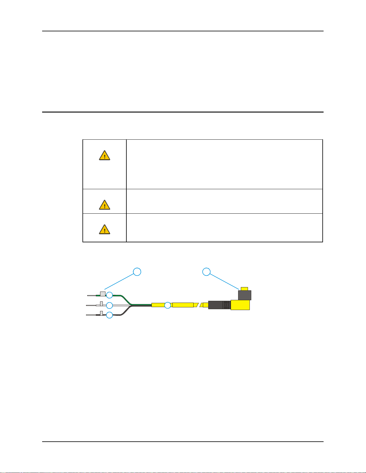
1. To Vehicle Battery
1 2
2. To Vehicle
Mounted Device
GND
3
+
4
-
5
6
3. Green (GND)
4. Brown (DC+)
5. Blue (DC-)
6. 12 VDC
Figure 25 Vehicle Power Connection Cable (Fuse Not Shown)
E-EQ-MX7DKRG-C MX7 Cradle Reference Guide
Page 40
34 Connect Power Supply to Vehicle
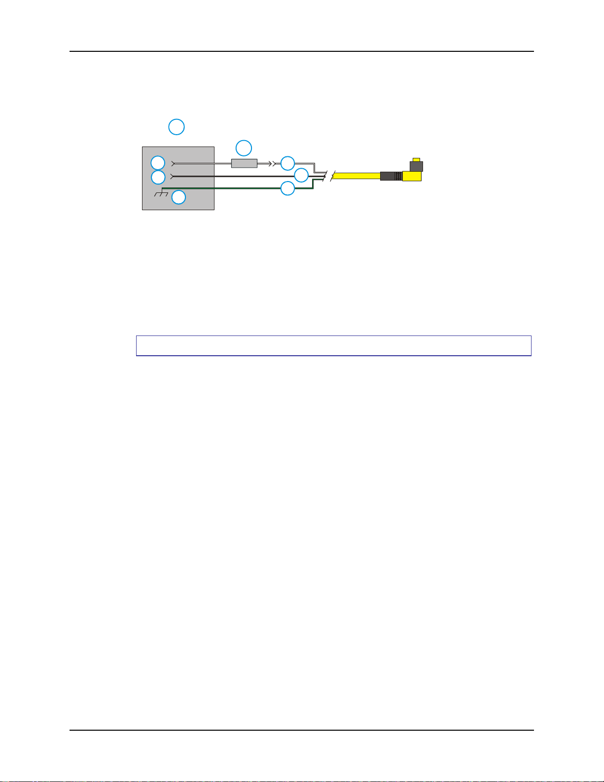
1. Vehicle Electrical
System
1
2
3
4
5
Figure 26 Connecting the Power Cable to the Vehicle
Note: Correct electrical polarity is required for safe and proper installation. The cradle will
not power on or function if the cable is connected with the polarity reversed. See the
following figure titled “Vehicle Connection Wiring Color Codes” for additional wire
color-coding specifics.
How To: Connect Vehicle 12 VDC Connection
1. The power cable must be UNPLUGGED from the MX7 vehicle cradle.
2. While observing the fuse requirements specified above, connect the power cable as
close as possible to the actual battery terminals of the vehicle. When available, always
connect to unswitched terminals in the vehicle fuse panel, after providing proper
fusing.
6
7
8
2. 10 Amp Slow
Blow Fuse
3. DC +
4. DC -
5. Vehicle Chassis
6. Brown
7. Blue
8. Green
ATTENTION: For uninterrupted power, electrical supply connections sho uld not
be made at any point after the ignition switch of the vehicle.
3. Route the power cable the shortest way possible. The cable is rated for a maximum
temperature of 105°C (221°F). When routing this cable it should be protected from
physical damage and from surfaces that might exceed this temperature.
Do not expose the cable to chemicals or oil that may cause the wiring insulation to
deteriorate.
Note: If the vehicle is equipped with a panel containing Silicon Controller Rectifiers
(SCR’s), avoid routing the power cable in close proximity to these devices.
Always route the cable so that it does not interfere with safe operation and maintenance
of the vehicle.
MX7 Cradle Reference Guide E-EQ-MX7DKRG-C
Page 41

Connect Power Supply to Vehicle 35
Use proper electrical and mechanical fastening means for terminating the cable.
Properly sized “crimp” type electrical terminals are an accepted method of termination.
Please select electrical connectors sized for use with 18AWG (1mm
Wiring color codes for LXE supplied DC input power cabling:
Vehicle Supply Wire Color
+12 VDC (DC +) Brown
Return (DC -) Blue
Vehicle Chassis GND Green
Figure 27 Vehicle Connection Wiring Color Codes
4. Provide mechanical support for the cable by securing it to the vehicle structure at
approximately one foot intervals, taking care not to over tighten and pinch conductors
or penetrate outer cable jacket.
5. Refer to the following sections to complete the power connection to the MX7 vehicle
cradle.
2
) conductors.
E-EQ-MX7DKRG-C MX7 Cradle Reference Guide
Page 42
36 Connect Power Supply to Vehicle Cradle
Connect Power Supply to Vehicle Cradle
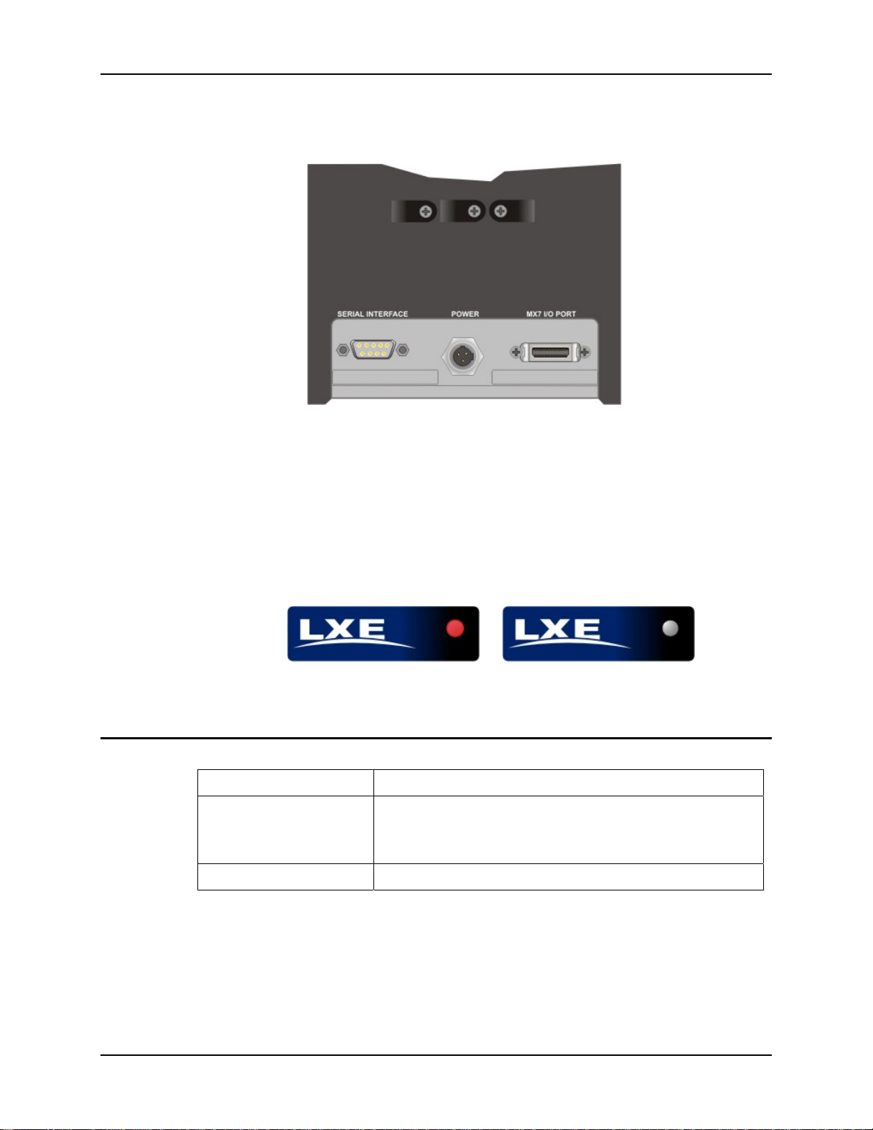
Figure 28 Connect Power Adapter Cable to the Vehicle Cradle
The power cable connector is L-shaped. The long end of the L (the cable) will be facing up
towards the middle strain relief cable clamp. Align the connector pins to the vehicle cradle Power
connector; firmly pushing the connector into the Power port. Tighten the nut of the plug clockwise
until the power cable is securely fastened. Secure the cable to the cradle with the LXE-installed
strain relief cable clamp (see section titled Vehicle Cradle Strain Relief Cable Clamp).
The power LED on the MX7 illuminates when it is receiving external power and an MX7 is
docked.
Vehicle Cradle LED
When Cradle LED is … It means ….
Off
Red
On Off
Figure 29 Powered Vehicle Cradle Front Label
1. MX7 is docked. Cradle does not have power.
2. MX7 is not docked. Cradle may have power. Check the
power connector at the back of the cradle.
MX7 is docked and external power is connected.
MX7 Cradle Reference Guide E-EQ-MX7DKRG-C
Page 43
Attach a Serial or I/O Connector 37
Attach a Serial or I/O Connector
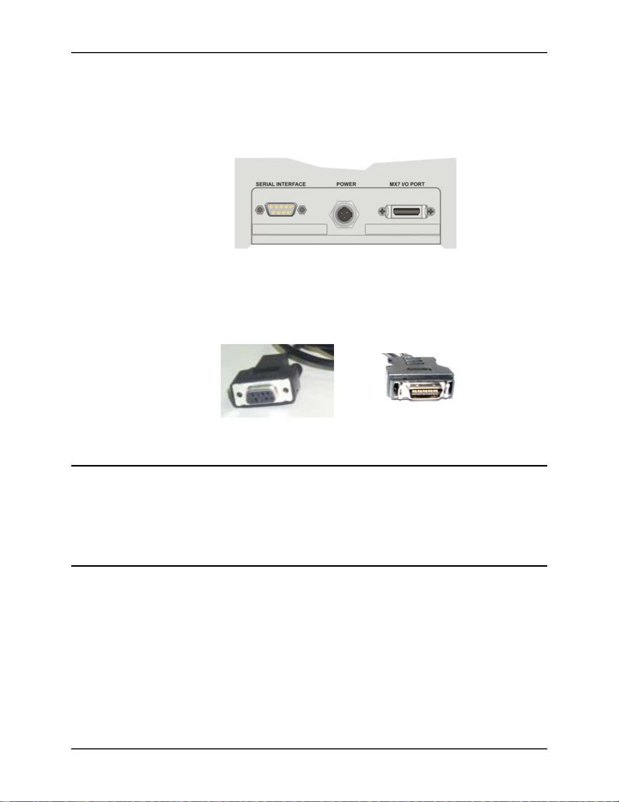
The serial cable is connected to the port labelled Serial Interface on the back of the vehicle cradle.
The serial cable can originate with a tethered scanner, a desktop/laptop PC, a printer or another
serial device.
Figure 30 Serial Connector, Power and MX7 I/O Connector
The I/O connector cable is connected to the port (male) labelled MX7 I/O Port on the back of the
vehicle cradle.
Serial Cable End MX7 I/O Cable End
Periodically test the connections for stability and re-tighten if necessary.
Serial Interface
Align the RS-232 serial cable end (female) carefully to the Serial Interface port (male) at the back
of the cradle. Firmly press the ends together and finger tighten the screws on either side of the
connector. Test the connection for stability.
Secure the cable to the cradle with the LXE-installed strain relief cable clamp (see section titled
Vehicle Cradle Strain Relief Cable Clamp).
MX7 I/O Port
Squeeze the clips next to the connector attached to the I/O cable to open the catches in the
connector assembly. Firmly press the cable end (female) into the MX7 I/O Port connector (male)
at the back of the cradle. Release the clips in the connector cable. Test the connection for
stability.
Secure the cable to the cradle with the LXE-installed strain relief cable clamp (see section titled
Vehicle Cradle Strain Relief Cable Clamp).
E-EQ-MX7DKRG-C MX7 Cradle Reference Guide
Page 44
38 Vehicle Cradle Strain Relief Cable Clamp
Vehicle Cradle Strain Relief Cable Clamp
Equipment Required: Phillips screwdriver (not supplied by LXE)
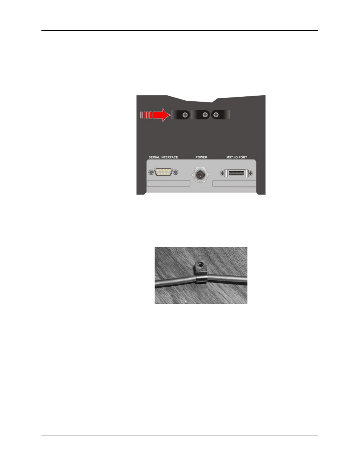
There are three strain relief cable clamps secured to the back of the vehicle cradle, located above
the ports for the Serial Interface, Power and MX7 I/O connections.
Figure 31 Vehicle Cradle Strain Relief Cable Clamps
1. Remove the strain relief clamp from the back of the cradle by turning the screw
counterclockwise. Put the screw aside in a safe location.
2. Slide the strain relief clamp over the cable.
Figure 32 Slide Clamp Over Cable
3. Using a Phillips screwdriver and the screw that was removed, refasten the clamp holding the
cable to the vehicle cradle. Do not stretch the cable. Leave enough slack in the cable to allow
it to be connected and disconnected easily when needed.
4. Continue in this manner until all cables are secured to the back of the vehicle cradle.
MX7 Cradle Reference Guide E-EQ-MX7DKRG-C
Page 45
Technical Specifications 39
Technical Specifications
Powered Vehicle Cradle
Weight 2 lbs. 15.2 oz / 1.34 kg
Dimensions Height 12.5 in. (31.8 cm)
Width 6.0 in. (15 cm)
Depth 5.0 in. (13 cm)
Operating Temperature 14° F to 122° F ( -10° C to 50° C)
Storage Temperature -4° F to 158° F (-20° C to 70° C)
Humidity 5% to 90% (non-condensing) at 104° F / 40° C
Cradle Power Connector Port
Note: When an external power supply is used to power these products, the external power
supply should be UL Listed, with LPS or Class 2 outputs rated 12V, minimum 2 Amps.
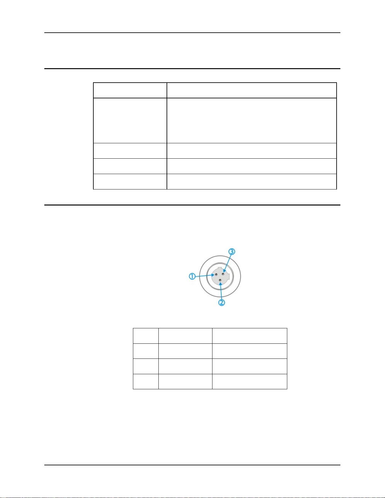
Pin Signal Wire Color
1 Ground (CG) Green
2 Return (-) Blue
3 +12V (+) Brown
Figure 33 Cradle Power Connector Port
Figure 34 Power Connector Pinout
The Power connector is located on the back of the vehicle cradle.
E-EQ-MX7DKRG-C MX7 Cradle Reference Guide
Page 46
40 Technical Specifications
Pinout - RS-232 Connector
Note: Tethered scanners must be connected to powered cradles.
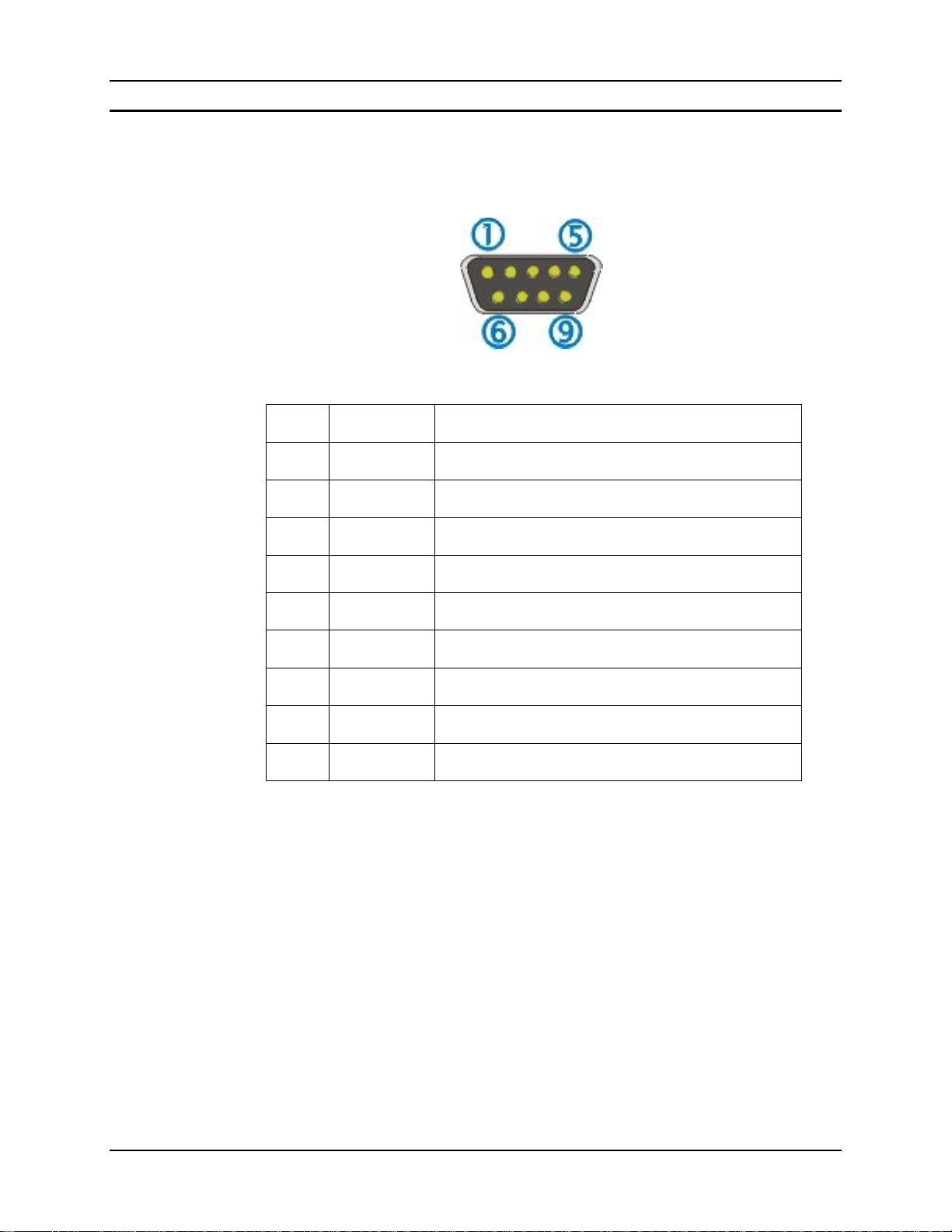
The connector is industry-standard RS-232 and is a PC/AT standard 9-pin D male connector.
Figure 35 Vehicle Cradle RS-232 and Pinout
Pin Signal Description
1 DCD Data Carrier Detect
2 RXD Received Data – Input
3 TXD Transmitted Data – Output
4 DTR Data Terminal Ready
5 GND Signal/Power Ground
6 DSR Data Set Ready
7 RTS Request to Send
8 CTS Clear To Send
9 RI or Power +5 VDC sourced by the Cradle
Note: Pin 9 of this port is connected to +5 VDC and only approved LXE cables are to be used
for communication between the cradle and external devices.
MX7 Cradle Reference Guide E-EQ-MX7DKRG-C
Page 47

Introduction
Passive Vehicle Mount Cradle
The MX7 passive vehicle mount cradle does not have an external device connector e.g.
power/serial cable. The cradle restrains the MX7 without a boot and with or without a handle or
strap.
Wireless communication is available as long as the mobile device has sufficient energy in the
main battery pack and a clear signal path.
The passive vehicle cradle is lined with strips of hook-and-loop fabric to ensure a snug fit between
the MX7 and the inside of the cradle.
There are two mounting options for the cradle:
• U-bracket mounting
• RAM ball cylinder mounting
Before installation begins, verify you have the applicable vehicle mounting bracket assembly
components necessary for your mount type, as shown in the next section titled “Components”.
Do not put the MX7 into the cradle until the cradle is securely fastened to the vehicle.
Quick Start - Passive Vehicle Cradle
There are two mounting options for the passive vehicle cradle:
• U-bracket mounting
• RAM ball cylinder mounting
The vehicle mounted cradle should be mounted in an area in the vehicle where it:
• Does not obstruct the driver's vision or safe vehicle operation.
• Will be protected from rain or inclement weather.
• Will be protected from extremely high concentrations of dust or wind-blown debris.
• Can be easily accessed by a user seated in the driver's seat while the vehicle is not in
operation.
1. Attach the RAM bracket or U-bracket mounting device to the vehicle.
2. Attach the passive cradle to the vehicle mounted bracket using the Angle Adjust knobs.
3. Adjust the cradle to the best viewing angle using the Angle Adjust knobs.
4. The Passive Vehicle Mount cradle is ready for use.
For installation instructions, see Passive Vehicle Mount Cradle later in this guide.
E-EQ-MX7DKRG-C MX7 Cradle Reference Guide
Page 48
42 Components
Components
Note: Bolts, washers, and wrench needed when attaching the mobile device to the vehicle are
not supplied by LXE.
U-Bracket
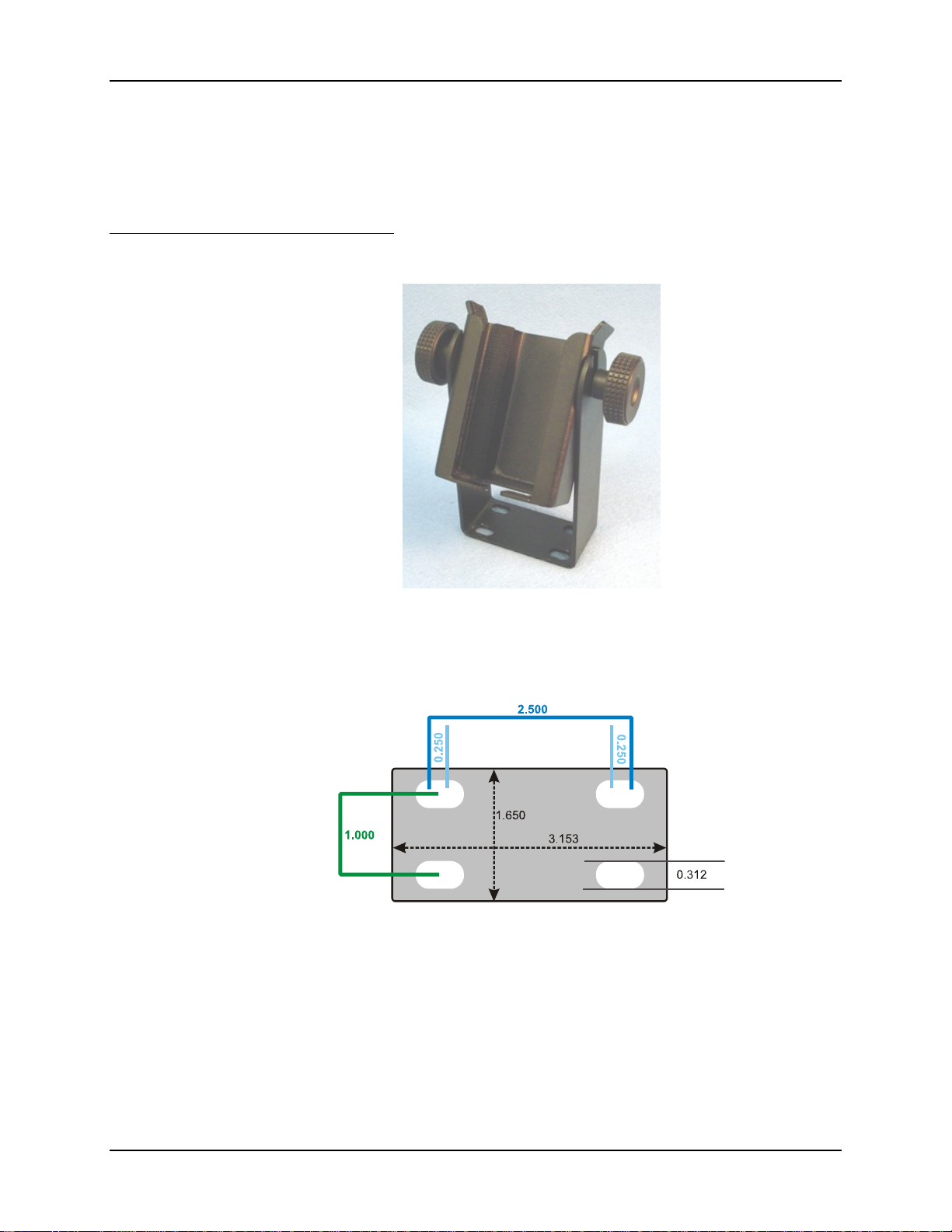
U-Bracket Footprint
Note: LXE does not supply the bolts or washers needed when mounting the cradle assembly to
Figure 36 Passive Vehicle Mount Cradle and U-Bracket
Not To Scale
Figure 37 U-Bracket Mounting Dimensions
the vehicle chassis. LXE recommends using bolts with a maximum 10/32” (0.3125)
diameter
MX7 Cradle Reference Guide E-EQ-MX7DKRG-C
Page 49
Components 43
RAM Ball and Cylinder
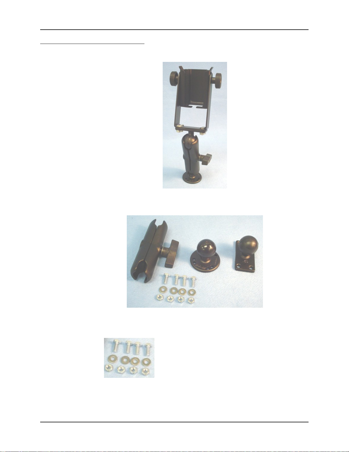
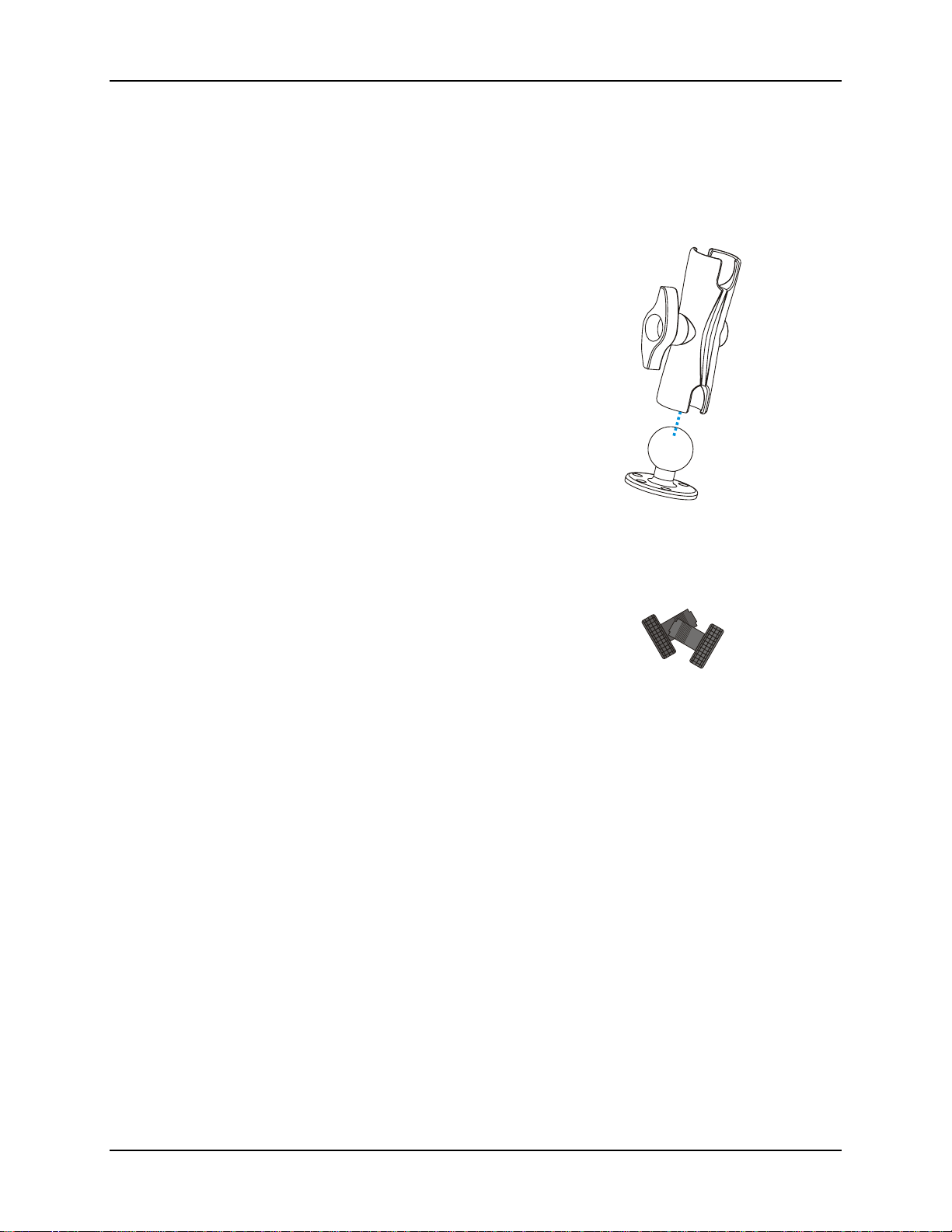
Figure 38 Passive Vehicle Mount Cradle / RAM Ball Assembly
Figure 39 RAM Bracket Components
Mount the cradle U-bracket to the upper RAM ball
assembly with the bolts, washers and nuts supplied by
LXE.
Qty 4 – Hex Cap ¼-20 x ¾ bolts
Qty 4 – ¼ flat washer
Qty 4 – 1/4-20 nylon insert lock nuts
E-EQ-MX7DKRG-C MX7 Cradle Reference Guide
Page 50
44 Install
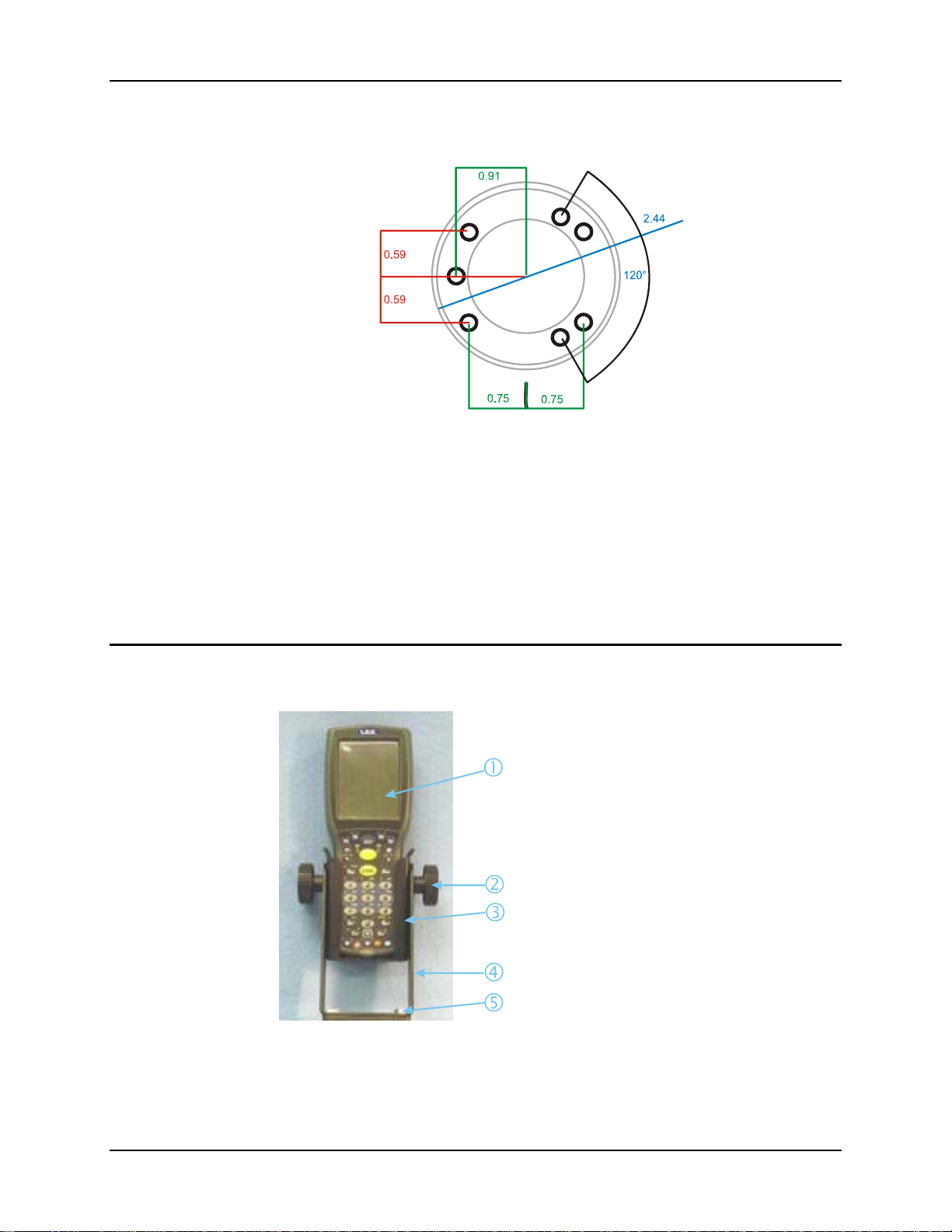
RAM Assembly Footprint
Not To Scale
Figure 40 RAM Assembly Dimensions
Note: LXE does not supply the bolts or washers needed when mounting the cradle assembly to
the vehicle chassis. LXE recommends using bolts with a maximum 10/32” (0.3125)
diameter.
Install
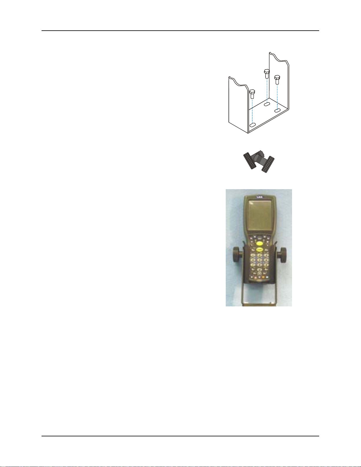
How to Install the Cradle U-Bracket
1. MX7
2. Angle Adjust Knob
3. Passive Cradle
4. U-Bracket
5. Mounting Bolt
Figure 41 Installing the Cradle U-Bracket
MX7 Cradle Reference Guide E-EQ-MX7DKRG-C
Page 51
Install 45
1. Attach the U-Bracket to the vehicle,
making sure it does not impede safe
operation of the vehicle.
2. Attach the Passive Cradle to the UBracket using the Angle Adjust knobs.
Use both knobs to loosen and tighten the
cradle to the U-bracket while
determining the best viewing angle.
3. The passive vehicle mounted cradle is
ready for use.
Periodically test the mounting device
and retighten bolts and/or knob as
needed. If the cradle becomes cracked or
warped it must be replaced.
E-EQ-MX7DKRG-C MX7 Cradle Reference Guide
Page 52
46 Install
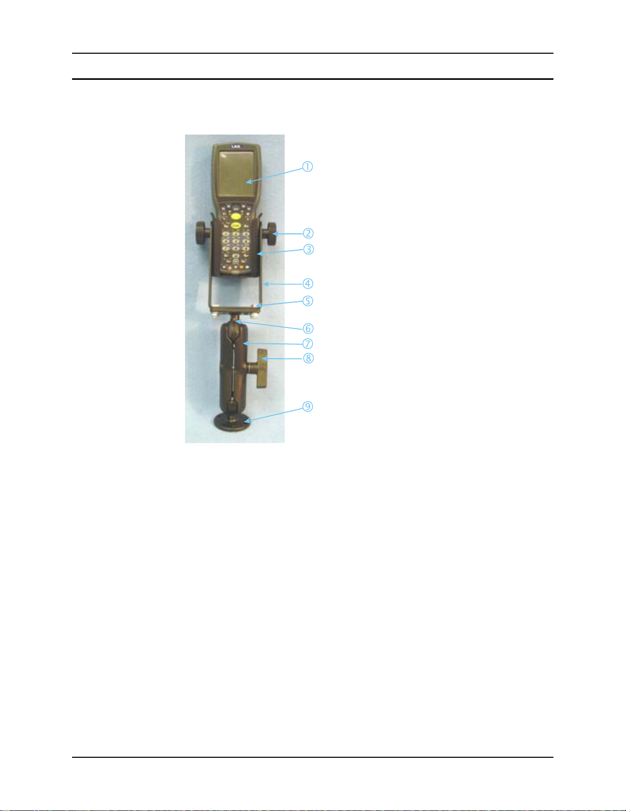
How to Install the RAM Bracket
1. MX7
2. Angle Adjust Knobs
3. Passive Cradle
4. U-Bracket
5. Mounting Hex Bolt
6. Upper RAM Ball Assembly
7. Arm
8. Thumbscrew
9. Lower RAM Ball Assembly
Figure 42 Installing the RAM Assembly
MX7 Cradle Reference Guide E-EQ-MX7DKRG-C
Page 53
Install 47
1. Attach the lower RAM ball assembly to the vehicle, making sure it does not impede
safe operation of the vehicle.
2. Fasten the upper RAM ball assembly to the base of the U-bracket using the supplied
bolts, washers and screws.
3. Loosen the turnscrew on the RAM arm,
place the lower socket over the vehicle
mount RAM ball, then the other arm
socket over the RAM ball on the Ubracket.
4. Tighten the arm turnscrew until the U-bracket is secured to the RAM arm and the
vehicle.
5. Attach the Passive Cradle to the UBracket using the Angle Adjust knobs.
Use both knobs to loosen and tighten the
cradle to the U-bracket while
determining the best viewing angle.
E-EQ-MX7DKRG-C MX7 Cradle Reference Guide
Page 54
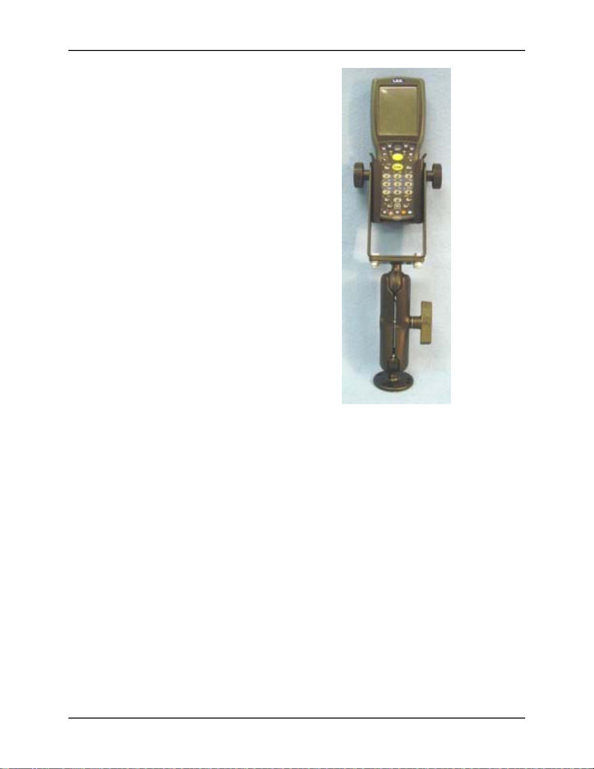
48 Install
6. The passive vehicle mounted cradle is
ready for use.
Periodically test the mounting device
and retighten bolts and/or knob as
needed. If the cradle becomes cracked or
warped it must be replaced.
MX7 Cradle Reference Guide E-EQ-MX7DKRG-C
Page 55
Appendix A Regulatory Notices and Safety Information
FCC Information:
This device complies with FCC Rules, part 15. Operation is subject to the following two conditions:
1. This device may not cause harmful interference,
and
2. This device must accept any interference received, including interference that may cause undesired operation.
Note: This equipment has been tested and found to comply with the limits for a Class A digital device, pursuant to part 15 of the
FCC rules. These limits are designed to provide reasonable protection against harmful interference when the equipment is
operated in a commercial environment. This equipment generates, uses, and can radiate radio frequency energy and, if not
installed and used in accordance with the instruction guide, may cause harmful interference to radio communications. Operation
of this equipment in a residential area is likely to cause harmful interference in which case the user will be required to correct the
interference at his own expense.
Warning: Changes or modifications to this device not expressly approved by LXE, Inc., could void the user’s authority to
operate this equipment.
EMC Directive Requirements:
This is a Class A product. In a domestic environment this product may cause radio interference in which case the user may be
required to take adequate measures.
Industry Canada:
This Class A digital apparatus meets all requirements of the Canadian Interference Causing Equipment Regulations. Operation is
subject to the following two conditions: (1) this device may not cause harmful interference, and (2) this device must accept any
interference received, including interference that may cause undesired operation.
Cet appareil numérique de la classe A respecte toutes les exigences du Règlement sur le matériel brouilleur du Canada.
Le présent appareil numérique n’émet pas de bruits radioélectriques dépassant les limites applicables aux appareils numériques
de Classe A prescrites dans le Règlement sur le brouillage radioélectrique édits par le ministère des Communications du Canada.
Cradle Approvals
Product EMI / EMC Standards Safety Standards
MX7 Desktop Cradle
MX7 Vehicle Mounted Cradle (Powered)
FCC Part 15 Subpart B,
Class A
EN 55022
Class A (CISPR 22)
EN 55024: 1998
AS/NZS 3548, Class A
(CISPR 22)
Important: This symbol is placed on the product to remind users to dispose of Waste Electrical and Electronic
Equipment (WEEE) appropriately, per Directive 2002-96-EC. In most areas, this product can be recycled,
reclaimed and re-used when properly discarded. Do not discard labeled units with trash. For information
about proper disposal, contact LXE through your local sales representative, or visit www lxe com.
E-EQ-MX7DKRG-C MX7 Cradle Reference Guide
UL 60950 / CSA C22.2 No. 60950
IEC/EN 60950-1
Page 56
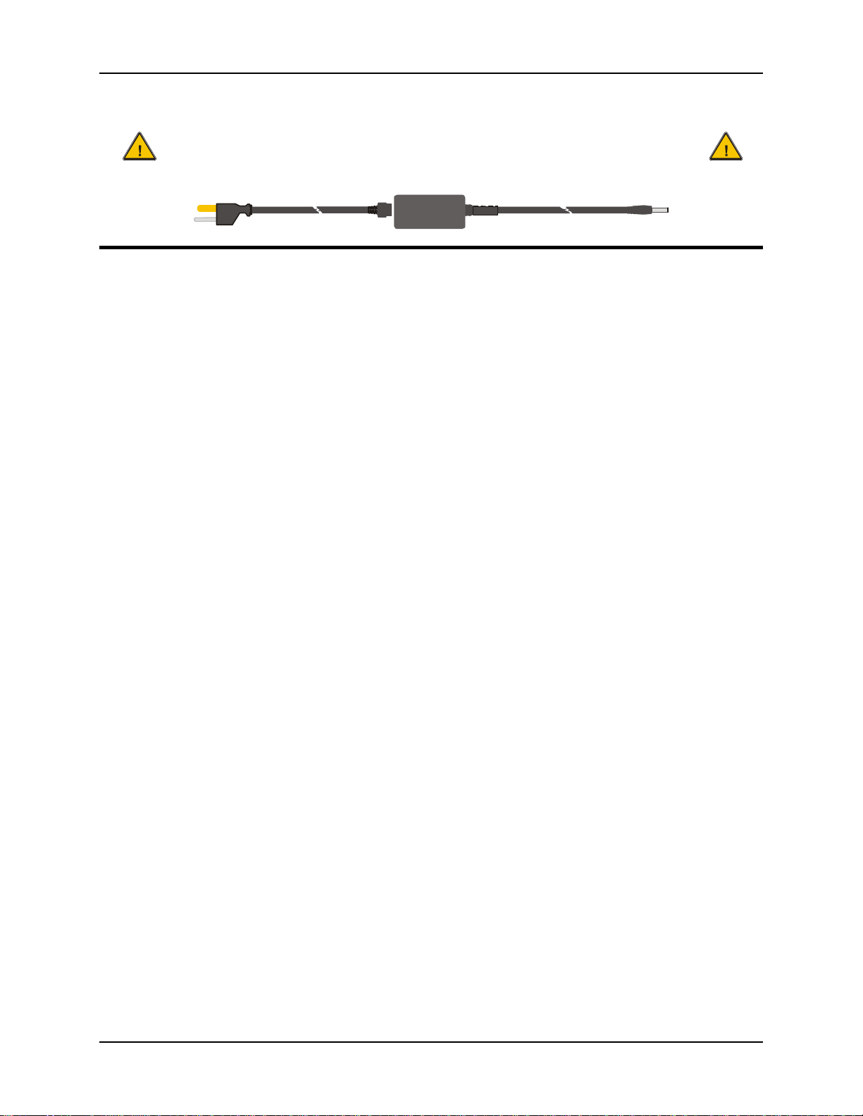
50 Appendix A Regulatory Notices and Safety Information
A/C Power Supply Safety Statement – MX7 Desktop
Cradle - Output Rated 12 VDC, 3.35 A.
Optional A/C Power Supply:
Outside North America, this unit is intended for use with an IEC certified ITE power supply with output rated as
stated at the top of this page. (US)
Alimentation c.a. optionnelle: -- Hors de l'Amérique du Nord, cette unité est conçue pour être utilisée avec une alimentation ITE
certifiée CEI de sortie nominale indiquée au haut de cette page. (FR)
Valgfrit vekselstrømforsygning -- Udenfor Nord Amerika er denne enhed udstattet med en IEC (international elektronisk
Kommission) udfærdiget med en ITE strømforsygning med strømudgang som fastslået på denne sides begyndelse. (DK)
Vaihtoehtoinen vaihtovirran syöttölaite: -- Pohjois-Amerikan ulkopuolella tämä laite on tarkoitettu käytettäväksi sellaisen IEC:n
sertifioiman ITE-tehonsyöttölaitteen kanssa, jonka antoteho on tämän sivun yläosassa esitetyn mukainen. (FI)
Optionales Netzteil (Wechselstrom) -- Außerhalb Nordamerikas sollte diese Einheit über ein der IEC-Norm entsprechendes ITENetzteil gespeist werden, und zwar mit einer wie oben auf dieser Seite genannten Ausspeisung. (DE)
Προαιρετική Τροφοδοσία Συνεχούς Ρεύματος -- Εκτός Β. Αμερικής, η μονάδα αυτή προορίζεται για χρήση με ένα τροφοδοτικό
ITE πιστοποιημένο κατά IEC με ονομαστική ισχύ όπως δηλώνεται στην αρχή της σελίδας. (GR)
Alimentazione opzionale a corrente alternata: -- Al di fuori dei paesi dell'America del nord, l'unità deve essere impiegata con un
dispositivo d'alimentazione per attrezzature informatiche approvato dalla IEC la cui potenza nominale sia pari a quella indicata
all'inizio della pagina. (IT)
Vekselstrømforsyning (ekstrautstyr): -- Utenfor Nord-Amerika skal dette produktet brukes med en IEC-sertifisert ITEstrømforsyning med klassifisert effekt som angitt øverst på denne siden. (NO)
Fornecimento opcional de CA: -- Fora dos EUA, esta unidade destina-se a ser usada com dispositivos de fornecimento de
corrente ITE com certificação IEC, com a capacidade indicada no topo desta página. (PT)
Suministro optativo de corriente alterna -- Fuera de América del Norte, esta unidad se debe utilizar con un alimentador ITE
homologado por la IEC (comisión electrotécnica internacional) con una salida que tenga la calificación que figura en la parte
superior de esta página. (ES)
Valfri A/C Strömförsörjning -- Utanför Nordamerika är det meningen att denna enheten används med en IEC-certifierad ITEströmförsörjare med den uteffekt som anges längst uppe på den här sidan. (SE)
İsteğe Bağlı A/C Güç Kaynağı: -- Kuzey Amerika dışında, bu ünite, çıkış sınıflandırması bu sayfanın başında belirtilen IEC
sertifikalı bir ITE güç kaynağı ile birlikte kullanılmak üzere tasarlanmıştır. (TR)
Updated 10/01/2001
Legend: Danish – DK; English – US; Finnish – FI; French- - FR; German – DE; Greek – GR; Italian – IT; Norwegian – NO;
Portuguese – PT; Spanish – ES; Swedish – SE; Turkish – TR.
MX7 Cradle Reference Guide E-EQ-MX7DKRG-C
Page 57

Appendix A Regulatory Notices and Safety Information 51
Vehicle Power Supply Connection Safety Statement
Vehicle Power Supply Connection:
If the supply connection is made directly to the battery, a 10A slow-blow fuse should be installed in the positive
lead within 5 inches (12.7 cm.) of the battery positive (+) terminal. (US)
Raccordement de l’alimentation du véhicule -- Si l’alimentation est raccordée directement à la batterie, un fusible à action
retardée de 10A doit être installé sur le câble positif à moins de 12,7 cm de la borne positive (+) de la batterie. (FR)
EL forsyning af køretøjet -- Er forsyningsforbindelsen direkte tilknyttet til batteriet og og tilsluttet til den positive part indenfor
12,7 cm (+ delen). vil der være en langsom tændelse af 10 ampere. (DK)
Kytkentä ajoneuvon virtalähteeseen -- Jos virtaa otetaan suoraan akusta, 10 ampeerin hidas sulake on asennettava positiiviseen
johtoon enintään 12 cm:n etäisyydelle akun positiivisesta (+) navasta. (FI)
Anschluss an Fahrzeugbatterie -- Bei direktem Anschluss an die Fahrzeugbatterie sollte eine träge 10A-Sicherung in die positive
Leitung zwischengeschaltet werden, und zwar nicht weiter als ca. 13 cm von der positiven (+) Batterieklemme entfernt. (DE)
Σύνδεση Τροφοδοτικού Ισχύος Οχήματος -- Αν η σύνδεση του τροφοδοτικού γίνει κατευθείαν στη μπαταρία, μια ασφάλεια
βραδείας τήξης των 10A θα πρέπει να τοποθετηθεί στο θετικό καλώδιο εντός 5 ιντσών (12,7 εκ.) του θετικού (+) ακροδέκτη της
μπαταρίας. (GR)
Collegamento dell’alimentazione del veicolo -- Se il collegamento dell’alimentazione viene stabilito direttamente con la batteria,
è necessario installare un fusibile ad azione lenta da 10 A nel conduttore positivo a meno di 5 in. (12,7 cm) dal terminale positivo
(+) della batteria. (IT)
Tilkople strømforsyningen til kjøretøyet -- Hvis strømforsyningen koples direkte til batteriet, skal det installeres en 10 A treg
sikring i den positive ledningen innen 12,7 cm fra plusspolen (+) på batteriet. (NO)
Ligação do fornecimento de corrente do veículo -- Se a ligação de fornecimento de corrente for ligada directamente à bateria,
deve instalar-se um fusível de 10A no terminal positivo, a 12,7 cm. do terminal positivo (+) da bateria. (PT)
Conexión de suministro eléctrico para el vehículo -- Si el suministro eléctrico se proporciona directamente a la batería, se debe
instalar un fusible de retardo de 10 A en el conductor positivo, como máximo a 12,7 cm (5 pulgadas) del terminal positivo (+).
(ES)
Fordonets strömförsörjningskoppling -- Om strömkopplingen görs direkt till batteriet, måste en 10A-säkring installeras i den
positivt laddade ledningen inom 12.7 cm från batteriets pluspol (+). (SE)
Taşıt Güç Kaynağı Bağlantısı -- Kaynak bağlantısı doğrudan aküye yapılırsa, pozitif bağlantı kablosu üzerinde akünün pozitif
(+) kutbuna 12.7 cm mesafede 10A’lık yavaş atan bir sigorta monte edilmelidir. (TR)
Legend: Danish – DK; English – US; Finnish – FI; French- - FR; German – DE; Greek – GR; Italian – IT; Norwegian – NO;
Portuguese – PT; Spanish – ES; Swedish – SE; Turkish – TR.
Updated 02/10/2004
E-EQ-MX7DKRG-C MX7 Cradle Reference Guide
Page 58

52 Appendix A Regulatory Notices and Safety Information
MX7 Cradle Reference Guide E-EQ-MX7DKRG-C
Page 59

Index 53
Index
Serial or IO Connection ................................19, 37
Strain Relief Cable Clamp ..................................38
A
AC Power Adapter Assembly..................................18
Adapter Cup ......................................................17, 26
Attach Vehicle Mounting Bracket...........................32
B
Base Plate ..................................................................8
Base Plate Kit Part Number.......................................8
Battery charging ......................................................21
Bluetooth ...................................................................6
C
Cables ......................................................................10
Cleaning.....................................................................7
Color Codes, Wiring................................................35
Components
Front, Back, Footprint.........................................14
Passive vehicle cradle .........................................42
Connect Serial or IO cables...............................19, 37
Cradle Accessories ..................................................10
D
Docked MX7 LED ....................................................4
G
Getting Help ............................................................10
I
Input Cable, Max Temp rating ................................34
L
LEDs..........................................................................4
M
Maintenance ..............................................................7
Manuals ...................................................................10
O
Operating Temperature............................................21
Powered Vehicle Cradle .....................................39
P
Passive vehicle cradle..............................................41
Passive Vehicle Cradle
footprint ..............................................................44
RAM assembly....................................................46
U bracket.............................................................44
Polarity ....................................................................34
Power Adapter.........................................................18
Power connector pinout...........................................39
Power Supply
Vehicle mount.....................................................33
H
Help .........................................................................10
How To
Adapter Cup..................................................17, 26
Connect 12-80VDC Vehicle Power....................34
Connect Power to Vehicle Cradle.......................36
Desktop Cradle ...................................................13
Desktop Mounting ..............................................16
Docking and undocking ......................................21
Insert or remove spare battery.............................22
Mounting Brackets, Passive Vehicle ..................41
Mounting Brackets, Vehicle ...............................23
Power Adapter ....................................................18
Prepare Desktop Cradle ......................................16
E-EQ-MX7DKRG-C MX7 Cradle Reference Guide
Q
Quick Start
Passive Vehicle Cradle .......................................41
R
Regulatory Notices ..................................................49
Replace MX7 Base Plate ...........................................8
RS-232 pinout, desktop cradle ................................20
RS-232 pinout, vehicle cradle .................................40
Page 60

54 Index
S
Safety Information...................................................49
Silicon Controller Rectifiers (SCR's) ......................34
Sizing of electrical connectors for use with 18AWG
conductors ...........................................................35
Spare battery charging.............................................22
Spare Battery LED ....................................................4
Specifications ..........................................................21
Storage Temperature ...............................................21
Strain Relief Cable Clamps .........................25, 36, 38
System Status LED................................................4, 5
T
Tethered Scanner .......................................................6
Tethered scanners ....................................................11
U
Upgrade MX7 base plate ...........................................8
V
Vehicle Mount Cradle, passive................................41
Vehicle mount cradle, powered
Components ........................................................24
Docking and Undocking the MX7......................29
Introduction.........................................................23
RAM bracket assembly.......................................30
Vehicle Mounting Bracket, Installation Procedure 23,
41
W
Wireless communication ...........................................1
Wiring Color Codes.................................................35
MX7 Cradle Reference Guide E-EQ-MX7DKRG-C
 Loading...