

Page 1
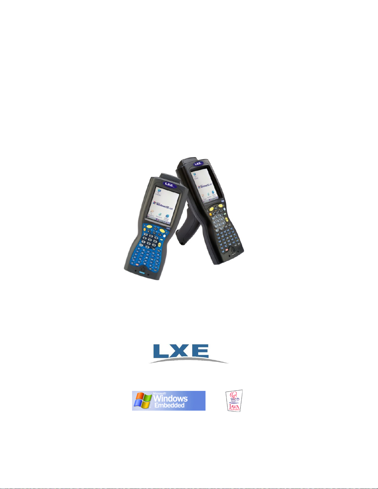
MX5X Reference Guide
(Microsoft® Windows® CE .NET 4.2 / CE 5.0 Equipped)
IMPORTANT NOTICE - The LXE MX5 CE .NET computers are obsolete. This electronic
manual has been made available as a courtesy to our customers. Please contact your LXE
customer support representative for replacement an d assistance.
Copyright © 2010 by LXE Inc.
All Rights Reserved
E-EQ-MX5CERG-F-ARC
Page 2

Notices
LXE Inc. reserves the right to make improvements or changes in the products described in this document at any time without
notice. While reasonable efforts have been made in the preparation of this document to assure its accuracy, LXE assumes no
liability resulting from any errors or omissions in this document, or from the use of the information contained herein. Further,
LXE Incorporated, reserves the right to revise this document and to make changes to it from time to time without any obligation
to notify any person or organization of such revision or changes.
Copyright:
This document is copyrighted. All rights are reserved. This document may not, in whole or in part, be copied, photocopied,
reproduced, translated or reduced to any electronic medium or machine-readable form without prior consent, in writing, from
LXE Inc.
Copyright © 2008 by LXE Inc. An EMS Technologies Company.
125 Technology Parkway, Norcross, GA 30092 U.S.A. (770) 447-4224
Trademarks:
LXE® and Spire® are registered trademarks of LXE Inc. RFTerm® is a registered trademark of EMS Technologies, Norcross,
GA.
Summit Data Communications, Inc. Summit Data Communications, the Summit logo, and “The Pinnacle of Performance” are
trademarks of Summit Data Communications, Inc.
Microsoft®, ActiveSync®, MSN, Outlook®, Windows®, the Windows logo, and Windows Media are either registered
trademarks or trademarks of Microsoft Corporation in the United States and/or other countries.
Java® and Java-based trademarks and logos are trademarks or registered trademarks of Sun Microsystems, Inc. in the U.S. or
other countries, and are used under license.
The Bluetooth® word mark and logos are owned by the Bluetooth SIG, Inc. and any use of such marks by LXE, Inc. is under
license.
PowerScan is a registered trademark of Datalogic Scanning, Inc., located in Eugene, OR.
Wavelink®, the Wavelink logo and tagline, Wavelink Studio™, Avalanche Management Console™, Mobile Manager™, and
Mobile Manager Enterprise™ are trademarks of Wavelink Corporation, Kirkland.
RAM® and RAM Mount™ are both trademarks of National Products Inc., 1205 S. Orr Street, Seattle, WA 98108.
All other brand or product names are trademarks or registered trademarks of their respective companies or organizations.
When this manual is in PDF format: “Acrobat® Reader® Copyright © 2008 Adobe Systems Incorporated. All rights reserved.
Adobe®, the Adobe logo, Acrobat®, and the Acrobat logo are registered trademarks of Adobe Systems Incorporated.” applies.
Initial Release, Dec 2004
Note: The original equipment’s User Manuals are copyrighted by Itronix® Corporation. This manual has been
amended by LXE® Inc., for the MX5X and MX5 Cradles with permission from Itronix Corporation.
Inspect enclosure for signs of deterioration such as cracking, warping, swelling or softening. Do not use
in Hazardous (Classified) Locations if there are any signs of deterioration.
Important: This symbol is placed on the product to remind users to dispose of Waste Electrical and
Electronic Equipment (WEEE) appropriately, per Directive 2002-96-EC. In most areas, this product can
be recycled, reclaimed and re-used when prope rly discarded. Do not discard labeled units with tras h.
For information about proper disposal, contact LXE through your local sales representative, or visit
www lxe com.
Page 3

Revision Notice
Chapter 3 – System
Configuration
Chapter 4 – Scanner Added Length Based Barcode Stripping.
Chapter 5 – Wireless Network
Configuration
Appendix C – MX5X CE
.NET 4.2
Appendix D – Reference
Material
Revised Wavelink Avalanche Enabler Configuration.
Added eXpress Scan section.
Removed Windows CE .NET 4.2 specific information and placed it in
Appendix C – MX5X CE .NET 4.2.
Added note to Profile Tab parameter Radi o Mo de .
Removed Cisco and Symbol radio sections and placed them in Appendix C
– MX5X CE .NET 4.2 section titled Wireless Network Configuration (CE
.NET 4.2).
New. Contains Windows CE .NET 4.2 specific information from Chapter 3
– System Configuration and Chapter 5 – Wireless Network Configuration.
Changed from Appendix C to D.
Page 4

Page 5

Table of Contents
CHAPTER 1 INTRODUCTION 1
Overview.................................................................................................................................................1
Important Battery Information..............................................................................................................2
Li-Ion Battery........................................................................................................................................ 2
When to Use This Guide........................................................................................................................2
Document Conventions.........................................................................................................................3
Identify Your Device ..............................................................................................................................4
MX5X Features .......................................................................................................................................5
Upgrading an MX5X to CE 5.0 ..............................................................................................................6
MX5X Hazardous Location Device....................................................................................................... 7
Getting Started.......................................................................................................................................8
Windows CE .NET 4.2..........................................................................................................................8
Windows CE 5.0................................................................................................................................... 8
Troubleshooting Start-up ......................................................................................................................9
Setup the Client and Network...............................................................................................................9
Access Terminal Emulation Parameters...........................................................................................10
Saving Settings....................................................................................................................................10
Components.........................................................................................................................................11
Power Key............................................................................................................................................. 14
Assembly..............................................................................................................................................15
Insert Main Battery .............................................................................................................................15
About Lithium-Ion Batteries ............................................................................................................ 15
Connect External Power Supply (Optional)........................................................................................ 16
Install Pistol Grip Handle (Optional)..................................................................................................17
Install Handstrap ................................................................................................................................. 18
How To..................................................................................................................................................20
Tap the Touchscreen with a Stylus ..................................................................................................... 20
Keypad Shortcuts..............................................................................................................................20
Calibrate the Touchscreen...................................................................................................................20
Set Time Zone (Optional) ................................................................................................................... 21
Enter Owner Information (Optional) .................................................................................................. 21
Set the Display and Keypad Backlight Timers ................................................................................... 21
Set the MX5X Power Schemes Timers............................................................................................... 22
Toggle the Display and Keypad Backlight On and Off ...................................................................... 22
Increase or Decrease Keypad and Display Backlight Intensity ..........................................................22
Connect Audio Jack (Optional)........................................................................................................... 22
Set The Audio Speaker Volume.......................................................................................................... 23
Troubleshooting Volume Adjust......................................................................................................23
Enter the Multi AppLock Activation Key........................................................................................... 24
Using a Stylus Tap............................................................................................................................24
Using the Switch Key Sequence....................................................................................................... 24
Copy the MX5X LXEbook to the MX5X (Optional) ......................................................................... 25
Enter Data.............................................................................................................................................26
Keypad Entry ...................................................................................................................................... 26
Stylus Data Entry ................................................................................................................................ 26
Scanner Entry...................................................................................................................................... 27
Data Entry and Tethered Scanners ................................................................................................... 27
Input Panel .......................................................................................................................................... 28
E-EQ-MX5CERG-F-ARC MX5X Reference Guide
Page 6

ii Table of Contents
RS-232 Data Entry..............................................................................................................................28
Getting Help..........................................................................................................................................29
Manuals............................................................................................................................................... 29
Accessories..........................................................................................................................................30
MX5X Standard................................................................................................................................30
MX5X ISAFE Device ......................................................................................................................31
CHAPTER 2 PHYSICAL DESCRIPTION AND LAYOUT 33
Hardware Configuration......................................................................................................................33
System Hardware................................................................................................................................33
Central Processing Unit.......................................................................................................................33
Core Logic...........................................................................................................................................33
System Memory..................................................................................................................................34
Video Subsystem.................................................................................................................................34
Power Supply......................................................................................................................................34
COM Ports .......................................................................................................................................... 35
Audio Interface ................................................................................................................................... 35
Power Key............................................................................................................................................. 36
Reboot Sequence.................................................................................................................................36
Warm Reset.........................................................................................................................................36
Cold Reset...........................................................................................................................................36
PCMCIA and Flash Cards.................................................................................................................... 37
Installation / Removal.........................................................................................................................38
PCMCIA Cards ................................................................................................................................38
Flash Cards.......................................................................................................................................38
Accessing the Data on CF and PCMCIA Cards.................................................................................. 39
ATA CF Card...................................................................................................................................39
Hatch CF Card..................................................................................................................................39
Hatch PCMCIA Card ....................................................................................................................... 39
COM Ports ............................................................................................................................................40
USB Port............................................................................................................................................. 40
Integrated Scanner Port (Optional) ............................................................................................. ........ 41
Tethered Scanners (Optional) ............................................................................................................. 41
Data Entry and Tethered Scanners ................................................................................................... 42
RS-232 Serial Ports............................................................................................................................. 42
COM1............................................................................................................................................... 42
COM4............................................................................................................................................... 42
USB Port............................................................................................................................................. 43
IR Port................................................................................................................................................. 43
Programmable Buttons.......................................................................................................................44
Power Modes........................................................................................................................................45
On Mode .............................................................................................................................................45
The Display ......................................................................................................................................45
The MX5X........................................................................................................................................45
LED Indicators ................................................................................................................................. 46
Suspend Mode.....................................................................................................................................46
The MX5X........................................................................................................................................46
Off Mode.............................................................................................................................................46
The Keypad...........................................................................................................................................47
Scan Key Function..............................................................................................................................47
Enter Key Function.............................................................................................................................48
2nd Key Function................................................................................................................................. 48
MX5X Reference Guide E-EQ-MX5CERG-F-ARC
Page 7

Table of Contents iii
Ctrl Key Function................................................................................................................................ 48
Alt Key Function................................................................................................................................. 48
Shft Key Function...............................................................................................................................48
Spc Key Function................................................................................................................................ 49
Field Exit Function.............................................................................................................................. 49
Mode Key Functions........................................................................................................................... 49
Caps Key and CapsLock Mode........................................................................................................49
Keypress Sequences............................................................................................................................49
Input Panel .......................................................................................................................................... 49
Accessing Files on the Compact Flash Card.................................................................................... 50
Touchscreen.........................................................................................................................................50
Display and Keypad Backlight Timer.................................................................................................50
Cleaning the Glass Display/Scanner Aperture.................................................................................51
Speaker.................................................................................................................................................51
Set The Audio / Speaker Volume........................................................................................................52
Using the Keypad............................................................................................................................. 52
Using the Touch Screen....................................................................................................................52
Troubleshooting.................................................................................................................................. 52
Power Supply .......................................................................................................................................53
Checking Battery Status......................................................................................................................53
Important Battery Information............................................................................................................53
Handling Batteries Safely ...................................................................................................................53
Main Battery Pack............................................................................................................................... 54
Battery Hot-Swapping......................................................................................................................... 54
Low Battery Warning.......................................................................................................................... 55
Battery Status LEDs............................................................................................................................ 55
Backup Battery.................................................................................................................................... 55
Battery Maintenance Publication........................................................................................................55
Battery Chargers..................................................................................................................................56
MX5 Multi-Charger (Optional)...........................................................................................................56
External Power Supply for MX5X and Cradle ................................................................................... 57
Cradles..................................................................................................................................................58
Tethered Barcode Scanner Data Entry Using the MX5 Cradle...........................................................59
CHAPTER 3 SYSTEM CONFIGURATION 61
Introduction..........................................................................................................................................61
Windows Operating System ...............................................................................................................61
Network Configuration........................................................................................................................61
Installed Software ................................................................................................................................61
Software Load.....................................................................................................................................62
Software Applications.........................................................................................................................62
Optional............................................................................................................................................... 62
AppLock (Option)............................................................................................................................62
JAVA (Option).................................................................................................................................63
LXE RFTerm (Option).....................................................................................................................63
Wavelink Avalanche Enabler (Option) ............................................................................................ 63
Desktop.................................................................................................................................................64
My Device Folders..............................................................................................................................65
Folders Copied at Startup.................................................................................................................65
Start Menu Program Options..............................................................................................................66
Communication................................................................................................................................... 66
ActiveSync..........................................................................................................................................67
E-EQ-MX5CERG-F-ARC MX5X Reference Guide
Page 8

iv Table of Contents
Synchronizing from the MX5X........................................................................................................67
Get Connected..................................................................................................................................67
Remote Desktop Connection...............................................................................................................68
Command Prompt ............................................................................................................................... 68
Inbox ................................................................................................................................................... 68
Internet Explorer ................................................................................................................................. 68
Media Player ....................................................................................................................................... 69
Windows Explorer ..............................................................................................................................69
Transcriber .......................................................................................................................................... 69
Taskbar................................................................................................................................................70
Advanced Tab................................................................................................................................... 70
Expand Control Panel....................................................................................................................70
Clear Contents of Document Folder .............................................................................................. 70
Control Panel Options......................................................................................................................... 71
Accessibility........................................................................................................................................72
Administration – for AppLock............................................................................................................73
Audio................................................................................................................................................... 74
Certificates .......................................................................................................................................... 75
Date/Time............................................................................................................................................76
Dialing................................................................................................................................................. 77
Display................................................................................................................................................ 78
Display Properties ............................................................................................................................ 78
Background.......................................................................................................................................78
Backlight .......................................................................................................................................... 78
Handheld.............................................................................................................................................79
How to Disable Touch and / or Calibration upon Cold Reset..........................................................79
Disable Touch Panel and Calibration ............................................................................................ 79
Disable Touch Panel Only.............................................................................................................79
How to Re-enable Touch and / or Calibration upon Cold Reset......................................................79
Handheld Properties ......................................................................................................................... 80
Versions tab ...................................................................................................................................80
Comms tab.....................................................................................................................................80
Radios tab ...................................................................................................................................... 81
Misc tab..........................................................................................................................................81
Input Panel .......................................................................................................................................... 82
Internet Options...................................................................................................................................83
Keyboard............................................................................................................................................. 84
Mouse.................................................................................................................................................. 85
Network and Dialup Connections.......................................................................................................85
Create a Communication Option......................................................................................................85
Owner..................................................................................................................................................86
Password ............................................................................................................................................. 87
PC Connection .................................................................................................................................... 87
Power ..................................................................................................................................................89
Status ................................................................................................................................................ 89
Battery .............................................................................................................................................. 89
Schemes............................................................................................................................................89
Regional Settings ................................................................................................................................ 90
Remove Programs............................................................................................................................... 90
Scanner................................................................................................................................................91
Determine Your Scanner Software Version.....................................................................................91
Factory Default Settings...................................................................................................................92
MX5X Reference Guide E-EQ-MX5CERG-F-ARC
Page 9

Table of Contents v
Main..................................................................................................................................................93
Keys..................................................................................................................................................94
Change a Virtual Key (F20 or F21) Value..................................................................................... 94
Advanced.......................................................................................................................................... 95
Translate Control Codes ................................................................................................................95
Strip Leading / Strip Trailing Characters.......................................................................................95
Prefix / Suffix.................................................................................................................................96
COM Ports........................................................................................................................................ 97
Good Scan and Bad Scan Sounds..................................................................................................... 97
Storage Manager ................................................................................................................................. 98
Stylus................................................................................................................................................... 99
Double Tap.......................................................................................................................................99
Calibration........................................................................................................................................99
System............................................................................................................................................... 100
General ...........................................................................................................................................100
Memory .......................................................................................................................................... 100
Device Name.................................................................................................................................. 101
Copyrights ...................................................................................................................................... 101
Compact Flash Cards, CAB Files and Programs ...........................................................................102
Access Files on the CF Card.............................................................................................................102
CF Files............................................................................................................................................. 102
API Calls..............................................................................................................................................103
ActiveSync / Get Connected Process.............................................................................................. 104
Introduction....................................................................................................................................... 104
Initial Install......................................................................................................................................105
Install ActiveSync on Desktop/Laptop...........................................................................................105
Serial Connection ........................................................................................................................... 105
USB Connection............................................................................................................................. 105
Connect – Initial Install Process.....................................................................................................106
Change Connection Parameters ........................................................................................................106
Backup MX5X Files Using ActiveSync ........................................................................................... 107
Prerequisites ...................................................................................................................................107
MX5X and PC Partnership............................................................................................................. 107
Serial Port Transfer.........................................................................................................................107
Infrared Port Transfer.....................................................................................................................107
USB Transfer..................................................................................................................................107
Ethernet Transfer............................................................................................................................107
Connect........................................................................................................................................... 107
Ethernet or Wireless Connection.................................................................................................... 108
Explore.............................................................................................................................................. 108
Disconnect......................................................................................................................................... 108
Serial Connection ........................................................................................................................... 108
IRDA Connection........................................................................................................................... 108
USB Connection............................................................................................................................. 108
Wireless Device Connection ..........................................................................................................108
Ethernet Connection.......................................................................................................................108
Cold Boot and Loss of Host Re-connection...................................................................................... 109
Troubleshooting ActiveSync.............................................................................................................109
iRescue ...............................................................................................................................................111
Start iRescue ..................................................................................................................................... 111
Backup Your Mobile Device using iRescue.....................................................................................111
Change Backup Settings ...................................................................................................................112
E-EQ-MX5CERG-F-ARC MX5X Reference Guide
Page 10

vi Table of Contents
Manage Backups...............................................................................................................................112
Restore Backups................................................................................................................................ 112
Wavelink Avalanche Enabler Configuration ................................................................................... 113
Briefly . . . ......................................................................................................................................... 113
Enabler Install Process......................................................................................................................113
Enabler Uninstall Process .................................................................................................................113
Stop the Enabler Service...................................................................................................................114
Update Monitoring Overview...........................................................................................................114
Mobile Device Wireless and Network Settings ................................................................................ 115
Enabler Configuration.......................................................................................................................116
File Menu Options..........................................................................................................................117
Avalanche Update using File | Settings.......................................................................................... 118
Menu Options .............................................................................................................................. 118
Connection Tab............................................................................................................................119
Execution Tab..............................................................................................................................120
Server Contact Tab ......................................................................................................................121
Startup/Shutdown Tab .................................................................................................................122
Scan Config Tab ..........................................................................................................................123
Display Tab..................................................................................................................................123
Shortcuts Tab...............................................................................................................................124
Adapters Tab................................................................................................................................125
Status Tab .................................................................................................................................... 128
Troubleshooting Avalanche Enabler.................................................................................................128
eXpress Scan .....................................................................................................................................129
CHAPTER 4 SCANNER 133
Introduction........................................................................................................................................133
Determine Your Scanner Software Version ....................................................................................133
Barcode Processing Overview.........................................................................................................134
Factory Default Settings....................................................................................................................135
Main Tab..............................................................................................................................................136
Parameters......................................................................................................................................... 136
Good Scan and Bad Scan Sounds ..................................................................................................... 137
Keys Tab.............................................................................................................................................137
Change a Virtual Key (F20 or F21) Value........................................................................................ 138
COM1/COM4 Tab................................................................................................................................139
Barcode Tab .......................................................................................................................................140
Buttons..............................................................................................................................................140
Enable Code ID................................................................................................................................. 141
Options ........................................................................................................................................... 141
Barcode – Symbology Settings.........................................................................................................142
Parameters ...................................................................................................................................... 143
Strip Leading/Trailing Control.......................................................................................................144
Barcode Data Match List.............................................................................................................145
Barcode Data Edit Buttons...........................................................................................................145
Match List Rules.......................................................................................................................... 146
Add Prefix/Suffix Control..............................................................................................................147
Barcode – Ctrl Char Mapping........................................................................................................... 148
Translate All...................................................................................................................................148
Barcode – Custom Identifiers............................................................................................................150
Parameters ...................................................................................................................................... 150
Buttons............................................................................................................................................151
MX5X Reference Guide E-EQ-MX5CERG-F-ARC
Page 11

Table of Contents vii
Control Code Replacement Examples.............................................................................................152
Barcode Processing Examples .......................................................................................................... 153
Length Based Barcode Stripping.....................................................................................................155
CHAPTER 5 WIRELESS NETWORK CONFIGURATION 157
Introduction........................................................................................................................................157
Summit Client Configuration............................................................................................................158
Summit Client Utility........................................................................................................................158
Help...................................................................................................................................................158
Summit Tray Icon .............................................................................................................................159
Wireless Zero Config Utility and the Summit Client.....................................................................159
Main Tab........................................................................................................................................... 160
Admin Login ..................................................................................................................................161
Config or Profile Tab........................................................................................................................162
Buttons............................................................................................................................................162
Config/Profile Parameters..............................................................................................................164
Status Tab.......................................................................................................................................... 166
Diags Tab..........................................................................................................................................167
Buttons............................................................................................................................................167
Global or Global Settings Tab...........................................................................................................168
Factory Default Settings.................................................................................................................168
Global Parameters ..........................................................................................................................169
Summit Wireless Security ................................................................................................................. 172
Sign-On vs. Stored Credentials ......................................................................................................173
Windows Certificate Store vs. Certs Path ...................................................................................... 175
User Certificates .......................................................................................................................... 175
Root CA Certificates.................................................................................................................... 175
No Security..................................................................................................................................... 176
WEP Keys ......................................................................................................................................177
LEAP w/o WPA Authentication.....................................................................................................178
EAP-FAST Authentication............................................................................................................. 179
PEAP/MSCHAP Authentication....................................................................................................181
WPA/LEAP Authentication ...........................................................................................................183
WPA PSK Authentication..............................................................................................................184
PEAP/GTC Authentication ............................................................................................................ 185
EAP-TLS Authentication ...............................................................................................................187
Certificates .........................................................................................................................................189
Root Certificates ............................................................................................................................... 189
Download a Root CA Certificate....................................................................................................189
Installing a Root CA Certificate on the Mobile Device .................................................................191
User Certificates................................................................................................................................ 193
Generating a User Certificate for the MX5X .................................................................................193
Installing a User Certificate on the MX5X (WPA-TLS Only).......................................................198
CHAPTER 6 APPLOCK 201
Introduction........................................................................................................................................201
Determine Your AppLock Version................................................................................................... 201
Setup a New Device........................................................................................................................... 202
Administration Mode.........................................................................................................................204
End User Mode...................................................................................................................................204
Passwords..........................................................................................................................................205
E-EQ-MX5CERG-F-ARC MX5X Reference Guide
Page 12

viii Table of Contents
AppLock Password Troubleshooting................................................................................................ 205
End-User Switching Technique........................................................................................................206
Using a Stylus Tap............................................................................................................................206
Using the Switch Key Sequence ....................................................................................................... 206
Multi-Application Configuration.......................................................................................................207
Application Panel.............................................................................................................................. 207
Launch Button................................................................................................................................209
Auto At Boot.............................................................................................................................209
Auto Re-Launch........................................................................................................................210
Manual (Launch)....................................................................................................................... 210
Allow Close............................................................................................................................... 211
End User Internet Explorer (EUIE) .............................................................................................211
Security Panel................................................................................................................................. 212
Setting an Activation Hotkey.......................................................................................................212
Setting a Password in the Security Panel..................................................................................... 213
Status Panel ....................................................................................................................................213
View.............................................................................................................................................213
Log............................................................................................................................................... 214
Save As........................................................................................................................................ 214
Troubleshooting AppLock................................................................................................................215
APPENDIX A KEY MAPS 217
Keypad................................................................................................................................................217
Key Map 101-Key Equivalencies .....................................................................................................218
IBM Keypad Overlays........................................................................................................................222
3270 Keypad ..................................................................................................................................... 222
5250 Keypad ..................................................................................................................................... 223
APPENDIX B TECHNICAL SPECIFICATIONS 225
Physical Specifications.....................................................................................................................225
Display Specifications....................................................................................................................... 226
Environmental Specifications ..........................................................................................................226
MX5X ............................................................................................................................................... 226
AC Wall Adapter .............................................................................................................................. 226
Network Card Specifications............................................................................................................227
Summit Client Type II ......................................................................................................................227
Symbol Client Type II....................................................................................................................... 227
Cisco Client Type II.......................................................................................................................... 227
APPENDIX C MX5X CE .NET 4.2 229
System Configuration CE .NET 4.2..................................................................................................229
Introduction....................................................................................................................................... 229
Windows Operating System CE .NET 4.2........................................................................................229
Installed Software CE .NET 4.2........................................................................................................ 229
Software Load ................................................................................................................................230
Software Applications .................................................................................................................... 230
Optional..........................................................................................................................................231
AppLock (Option)........................................................................................................................231
JAVA (Option) ............................................................................................................................231
LXE RFTerm (Option) ................................................................................................................231
MX5X Reference Guide E-EQ-MX5CERG-F-ARC
Page 13

Table of Contents ix
Wavelink Avalanche Enabler ...................................................................................................... 231
Bluetooth Manager (CE .NET 4.2 only)...................................................................................... 231
Desktop CE .NET 4.2........................................................................................................................232
My Computer Folders (CE .NET 4.2)............................................................................................... 233
Folders Copied at Startup...............................................................................................................233
Start Menu Program Options CE .NET 4.2.......................................................................................234
Communication .............................................................................................................................. 234
ActiveSync .....................................................................................................................................235
Synchronizing from the MX5X................................................................................................... 235
Get Connected..............................................................................................................................235
Remote Desktop Connection.......................................................................................................... 235
Command Prompt........................................................................................................................... 236
Inbox............................................................................................................................................... 236
Internet Explorer............................................................................................................................. 236
Media Player................................................................................................................................... 236
Windows Explorer..........................................................................................................................236
Transcriber...................................................................................................................................... 236
Taskbar...........................................................................................................................................237
Advanced Tab..............................................................................................................................237
Expand Control Panel................................................................................................................237
Clear Contents of Document Folder.......................................................................................... 237
Control Panel Options CE .NET 4.2.................................................................................................238
Accessibility...................................................................................................................................240
Administration – for AppLock.......................................................................................................240
Audio..............................................................................................................................................241
Certificates...................................................................................................................................... 242
Date/Time....................................................................................................................................... 243
Dialing............................................................................................................................................243
Display............................................................................................................................................ 244
Display Properties........................................................................................................................ 244
Background.................................................................................................................................. 244
Backlight...................................................................................................................................... 244
Handheld ........................................................................................................................................ 245
How to Disable Touch and / or Calibration upon Cold Reset......................................................245
Disable Touch Panel and Calibration .......................................................................................... 245
Disable Touch Panel Only...........................................................................................................245
How to Re-enable Touch and / or Calibration upon Cold Reset..................................................245
Bootloader Version 1.02................................................................................................................. 246
Versions tab .................................................................................................................................246
Comms tab...................................................................................................................................246
Radios tab .................................................................................................................................... 247
Misc tab........................................................................................................................................247
Bootloader Version 1.01................................................................................................................. 248
Versions tab .................................................................................................................................248
Comms tab...................................................................................................................................248
Radios tab .................................................................................................................................... 248
Misc tab........................................................................................................................................248
Input Panel...................................................................................................................................... 249
Internet Options.............................................................................................................................. 250
Windows CE .NET 4.2 Defaults..................................................................................................250
Keyboard ........................................................................................................................................ 250
Mouse.............................................................................................................................................250
E-EQ-MX5CERG-F-ARC MX5X Reference Guide
Page 14

x Table of Contents
Network and Dialup Connections...................................................................................................251
Create a Communication Option ................................................................................................. 251
Owner.............................................................................................................................................252
Password......................................................................................................................................... 253
PC Connection................................................................................................................................ 253
Power..............................................................................................................................................254
Status............................................................................................................................................ 254
Battery.......................................................................................................................................... 254
Schemes.......................................................................................................................................254
Regional Settings............................................................................................................................ 255
Remove Programs ..........................................................................................................................255
Scanner...........................................................................................................................................256
Determine Your Scanner Software Version.................................................................................256
Factory Default Settings ..............................................................................................................257
Main............................................................................................................................................. 258
Keys.............................................................................................................................................259
Change a Virtual Key (F20 or F21) Value................................................................................259
Advanced..................................................................................................................................... 260
Translate Control Codes............................................................................................................260
Strip Leading / Strip Trailing Characters .................................................................................. 260
Prefix / Suffix............................................................................................................................ 261
COM Ports...................................................................................................................................262
Good Scan and Bad Scan Sounds................................................................................................262
Storage Manager............................................................................................................................. 263
Stylus.............................................................................................................................................. 264
Double Tap .................................................................................................................................. 264
Calibration ................................................................................................................................... 264
System ............................................................................................................................................ 265
General.........................................................................................................................................265
Memory........................................................................................................................................ 265
Device Name................................................................................................................................ 266
Copyrights.................................................................................................................................... 266
Wireless Network Configuration (Cisco and Symbol Clients) ...................................................... 267
Cisco Client Configuration (CE .NET 4.2 only)...............................................................................267
Aironet Client Utility (ACU).......................................................................................................... 267
Profiles Tab..................................................................................................................................267
Firmware Tab............................................................................................................................... 267
Status Tab .................................................................................................................................... 267
Statistics Tab................................................................................................................................268
Survey Tab................................................................................................................................... 268
Cisco Wireless Security.................................................................................................................. 268
System Requirements...................................................................................................................268
Installing Cisco Wireless Client Drivers...................................................................................... 268
Checking for the Cisco PEAP Supplicant.................................................................................... 269
Cisco WPA Configuration...........................................................................................................270
PEAP/MS-CHAP Authentication Configuration......................................................................... 273
Configuring the PEAP/MS-CHAP Supplicant..........................................................................273
Server Authentication................................................................................................................ 275
PEAP / GTC Authentication Configuration.................................................................................276
Configuring the PEAP/GTC Supplicant....................................................................................276
Server Authentication................................................................................................................ 278
WPA/LEAP .................................................................................................................................279
MX5X Reference Guide E-EQ-MX5CERG-F-ARC
Page 15

Table of Contents xi
Cisco ACU ................................................................................................................................ 279
EAP-TLS Authentication Configuration .....................................................................................281
User Certificate .........................................................................................................................281
Setting EAP/TLS Parameters....................................................................................................282
Validating the Server Certificate............................................................................................... 284
WPA PSK Configuration............................................................................................................. 285
Symbol Client (CE .NET 4.2 only)...................................................................................................286
IP Information Tab......................................................................................................................... 286
IPv6 Information Tab.....................................................................................................................286
Configuring IPv6............................................................................................................................ 286
Wireless Information Tab...............................................................................................................286
View Log ..................................................................................................................................... 287
Add a new connection.................................................................................................................... 287
Disable WEP................................................................................................................................287
Enable WEP................................................................................................................................. 287
Continue....................................................................................................................................... 287
Select a User Certificate...............................................................................................................287
APPENDIX D REFERENCE MATERIAL 289
Introduction........................................................................................................................................289
AppLock - Single Application Configuration..................................................................................290
Determine Your AppLock Version................................................................................................... 290
Setup a New Device.......................................................................................................................... 291
Administration Mode........................................................................................................................291
End User Mode ................................................................................................................................. 292
Passwords..........................................................................................................................................292
Password Troubleshooting ............................................................................................................. 292
Single Application Configuration..................................................................................................... 293
Administrator Control Panels.........................................................................................................293
Control Panel.................................................................................................................................. 294
End User Internet Explorer..........................................................................................................294
Security Panel ................................................................................................................................... 295
Specify a Hotkey Sequence............................................................................................................295
Setting a Password.......................................................................................................................... 295
Status Panel.......................................................................................................................................296
View ...............................................................................................................................................296
Levels .............................................................................................................................................297
Save As........................................................................................................................................... 297
AppLock Error Messages..................................................................................................................298
AppLock Registry Settings...............................................................................................................303
Valid VK Codes for CE.......................................................................................................................304
ASCII Control Codes..........................................................................................................................305
Hat Encoding......................................................................................................................................307
Decimal – Hexadecimal Chart...........................................................................................................309
Revision History.................................................................................................................................311
INDEX 313
E-EQ-MX5CERG-F-ARC MX5X Reference Guide
Page 16

xii Table of Contents
Illustrations
Figure 1-1 Identify your Device...........................................................................................................................4
Figure 1-2 Features..............................................................................................................................................5
Figure 1-3 Front of MX5X.................................................................................................................................11
Figure 1-4 Scan Aperture and Audio Jack.........................................................................................................11
Figure 1-5 Ports..................................................................................................................................................12
Figure 1-6 Back w/Optional Handle or Hand Strap...........................................................................................12
Figure 1-7 Handle (Optional).............................................................................................................................13
Figure 1-8 Power Key Location.........................................................................................................................14
Figure 1-9 Main Battery Pack............................................................................................................................15
Figure 1-10 AC/DC 12V External Power Supply..............................................................................................16
Figure 1-11 Battery Charging LED....................................................................................................................16
Figure 1-12 Trigger Handle Attach Points.........................................................................................................17
Figure 1-13 MX5X With Handstrap Installed....................................................................................................18
Figure 1-14 Upper Strap Bracket.......................................................................................................................18
Figure 1-15 Strap Inserted in Upper Bracket.....................................................................................................19
Figure 1-16 Connect Audio Jack........................................................................................................................22
Figure 1-17 End-User Multi AppLock Touch Panel Segment...........................................................................24
Figure 1-18 Scan Beam......................................................................................................................................27
Figure 1-19 Scanner LED Location...................................................................................................................27
Figure 1-20 Input Panel...................................................................................................................................... 28
Figure 2-1 System Hardware .............................................................................................................................33
Figure 2-2 COM Ports – Left and Right ............................................................................................................35
Figure 2-3 PCMCIA Wireless Client Card and Flash Card Location................................................................37
Figure 2-4 COM Ports........................................................................................................................................ 40
Figure 2-5 RS-232 Ports ....................................................................................................................................42
Figure 2-6 DB26 RS-232 Pinouts......................................................................................................................42
Figure 2-7 MX5X USB Port..............................................................................................................................43
Figure 2-8 USB-Serial Cable Pinouts................................................................................................................43
Figure 2-9 IR Port on MX5X.............................................................................................................................43
Figure 2-10 Scan Buttons...................................................................................................................................44
Figure 2-11 Power Modes – On, Suspend and Off............................................................................................45
Figure 2-12 The ANSI / Batch Keypad..............................................................................................................47
Figure 2-13 Touchscreen ...................................................................................................................................50
Figure 2-14 Speaker Location............................................................................................................................51
Figure 2-15 LXE Multi-Charger........................................................................................................................56
Figure 2-16 Insert Battery Pack in Charging Pocket..........................................................................................56
Figure 2-17 AC/DC 12V Power Supply ............................................................................................................57
Figure 3-1 Desktop Icons...................................................................................................................................64
Figure 3-2 Pocket CMD Prompt Screen ............................................................................................................68
Figure 3-3 Taskbar and Start Menu Properties ..................................................................................................70
Figure 3-4 Accessibility Options .......................................................................................................................72
Figure 3-5 Audio Properties...............................................................................................................................74
Figure 3-6 Digital Certificates ...........................................................................................................................75
Figure 3-7 Date/Time Properties........................................................................................................................76
Figure 3-8 Dialing Properties.............................................................................................................................77
Figure 3-9 Display Properties ............................................................................................................................78
Figure 3-10 Handheld Properties – Version 1.02...............................................................................................80
Figure 3-11 Input Panel...................................................................................................................................... 82
Figure 3-12 Keyboard Properties.......................................................................................................................84
Figure 3-13 Owner Properties............................................................................................................................86
Figure 3-14 PC Connection / Change Connection.............................................................................................88
Figure 3-15 Power Properties.............................................................................................................................89
Figure 3-16 Remove/Delete User Installed Programs........................................................................................90
Figure 3-17 Determine Your Scanner Software Version...................................................................................91
MX5X Reference Guide E-EQ-MX5CERG-F-ARC
Page 17

Table of Contents xiii
Figure 3-18 Scanner Properties / Main Tab.......................................................................................................93
Figure 3-19 Scanner Properties / Keys Tab .......................................................................................................94
Figure 3-20 Scanner Properties / Advanced tab.................................................................................................95
Figure 3-21 Scanner Properties / COM Port Settings........................................................................................97
Figure 3-22 Storage Properties...........................................................................................................................98
Figure 3-23 Stylus Properties / Calibration Start / Calibration Begin................................................................99
Figure 3-24 System / Memory.........................................................................................................................100
Figure 3-25 System / Device Name.................................................................................................................101
Figure 3-26 iRescue Backup............................................................................................................................111
Figure 3-27 Avalanche Enabler Opening Screen.............................................................................................116
Figure 3-28 Connection Options......................................................................................................................119
Figure 3-29 Execution Options (Dimmed).......................................................................................................120
Figure 3-30 Server Contact Options.................................................................................................................121
Figure 3-31 Startup / Shutdown Options..........................................................................................................122
Figure 3-32 Scan Config Option......................................................................................................................123
Figure 3-33 Window Display Options.............................................................................................................123
Figure 3-34 Application Shortcuts...................................................................................................................124
Figure 3-35 Adapters Options – Network........................................................................................................125
Figure 3-36 Avalanche Network Profile Displayed.........................................................................................126
Figure 3-37 Manual Settings Properties Panels...............................................................................................127
Figure 3-38 Status Display...............................................................................................................................128
Figure 3-39 eXpress Scan Desktop Icon..........................................................................................................129
Figure 3-40 eXpress Scan Password Input.......................................................................................................129
Figure 3-41 Scan Barcode 1.............................................................................................................................130
Figure 3-42 Scan Remaining Barcodes............................................................................................................130
Figure 3-43 Configuring Settings.....................................................................................................................131
Figure 4-1 Scanner Control / Main..................................................................................................................136
Figure 4-2 Scanner Properties / Keys Tab.......................................................................................................137
Figure 4-3 Scanner Control / COM1 and COM4.............................................................................................139
Figure 4-4 Scanner Control / Barcode tab........................................................................................................140
Figure 4-5 Barcode Tab – Symbology Settings...............................................................................................142
Figure 4-6 Strip Leading / Trailing and Barcode Data.....................................................................................144
Figure 4-7 Barcode Data Match List................................................................................................................145
Figure 4-8 Add Prefix/Suffix Control..............................................................................................................147
Figure 4-9 Barcode Tab – Ctrl Char Mapping.................................................................................................148
Figure 4-10 Barcode Tab – Custom Identifiers................................................................................................150
Figure 4-11 Control Code Replacement Examples..........................................................................................152
Figure 4-12 Barcode Processing Examples......................................................................................................154
Figure 5-1 Summit Client Utility (SCU)..........................................................................................................158
Figure 5-2 SCU – Main Tab.............................................................................................................................160
Figure 5-3 Main Tab – Enter Admin Password ...............................................................................................161
Figure 5-4 SCU – Config / ProfileTab.............................................................................................................162
Figure 5-5 SCU - Scan.....................................................................................................................................163
Figure 5-6 SCU – Status Tab...........................................................................................................................166
Figure 5-7 SCU – Diags Tab............................................................................................................................167
Figure 5-8 SCU – Global /Global Settings Tab...............................................................................................168
Figure 5-9 Sign-On Screen ..............................................................................................................................174
Figure 5-10 Choose Certificate........................................................................................................................175
Figure 5-11 Configure a Summit Profile with No Security .............................................................................176
Figure 5-12 Summit WEP Key Dialog ............................................................................................................177
Figure 5-13 Configure a Summit Profile for LEAP w/o WPA........................................................................178
Figure 5-14 LEAP Credentials Dialog.............................................................................................................178
Figure 5-15 Configure a Summit Profile for EAP-FAST ................................................................................179
Figure 5-16 Summit EAP-FAST Credentials...................................................................................................180
Figure 5-17 Configure a Summit Profile for PEAP/MSCHAP........................................................................181
Figure 5-18 PEAP/MSCHAP Credentials Dialog............................................................................................182
Figure 5-19 Configure a Summit Profile with LEAP for WPA TKIP.............................................................183
E-EQ-MX5CERG-F-ARC MX5X Reference Guide
Page 18

xiv Table of Contents
Figure 5-20 LEAP Credentials.........................................................................................................................183
Figure 5-21 Configure a Summit Profile with WPA PSK Encryption.............................................................184
Figure 5-22 Summit PSK Entry Dialog ...........................................................................................................184
Figure 5-23 Configure a Summit Profile with PEAP/GTC..............................................................................185
Figure 5-24 PEAP/GTC Credentials Dialog....................................................................................................186
Figure 5-25 Configure a Summit Profile with EAP-TLS.................................................................................187
Figure 5-26 EAP-TLS Credentials Dialog.......................................................................................................188
Figure 5-27 Logon to Certificate Authority.....................................................................................................189
Figure 5-28 Certificate Services Welcome Screen...........................................................................................189
Figure 5-29 Download CA Certificate Screen.................................................................................................190
Figure 5-30 Download CA Certificate Save to Desktop..................................................................................190
Figure 5-31 Certificate Stores..........................................................................................................................191
Figure 5-32 Import Certificate From a File......................................................................................................191
Figure 5-33 Browsing to Certificate Location .................................................................................................192
Figure 5-34 Logon to Certificate Authority.....................................................................................................193
Figure 5-35 Certificate Services Welcome Screen...........................................................................................193
Figure 5-36 Request a Certificate Type...........................................................................................................194
Figure 5-37 Advanced Certificate Request Screen ..........................................................................................194
Figure 5-38 Advanced Certificate Details........................................................................................................195
Figure 5-39 Script Warnings............................................................................................................................196
Figure 5-40 Script Warnings............................................................................................................................196
Figure 5-41 User Certificate Issued .................................................................................................................197
Figure 5-42 Download Certificate Security Warning ......................................................................................197
Figure 5-43 Certificate Stores..........................................................................................................................198
Figure 5-44 Import User Certificate.................................................................................................................198
Figure 5-45 Browsing to Certificate Location .................................................................................................199
Figure 5-46 User Certificate Listing ................................................................................................................199
Figure 5-47 Browsing to Private Key Location...............................................................................................200
Figure 6-1 Determine Your AppLock Version................................................................................................201
Figure 6-2 AppLock Panels .............................................................................................................................203
Figure 6-3 Switchpad Menu.............................................................................................................................206
Figure 6-4 Application Panel – Multi-Application ..........................................................................................207
Figure 6-5 Application Launch Options...........................................................................................................209
Figure 6-6 Security Panel – Multi-Application................................................................................................212
Figure 6-7 Status Panel – Multi-Application ...................................................................................................213
MX5X Reference Guide E-EQ-MX5CERG-F-ARC
Page 19
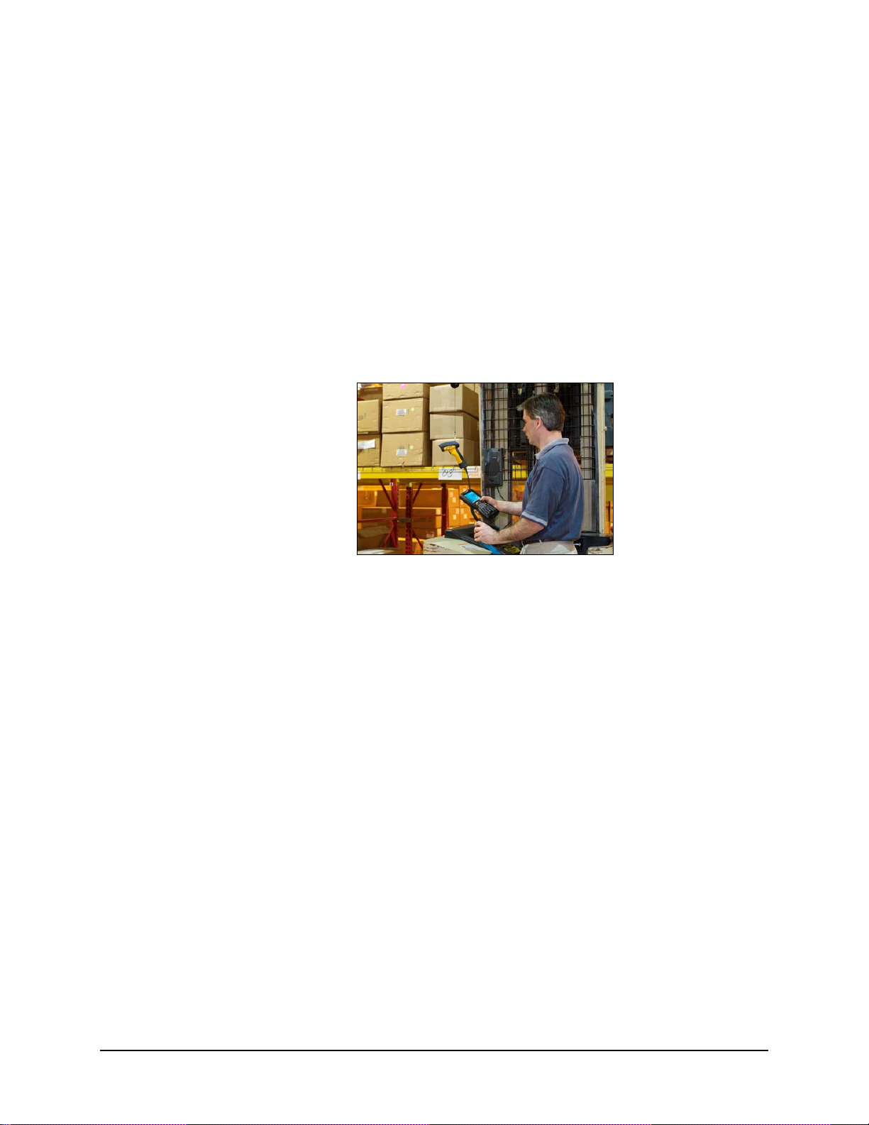
Overview
Chapter 1 Introduction
Note: At the bottom of the MX5X is a label tha t indicates the operating system resident on the
mobile device. This guide is directed toward an MX5X with Windows CE on the label.
The LXE® MX5X is a rugged, portable, hand-held Microsoft® Windows® CE .NET 4.2 or CE
5.0 equipped mobile computer capable of wireless data communications. The MX5X can transmit
information using a 2.4 GHz wireless client (with dual internal antennas) and it can store
information for later transmission using an RS-232 serial port, Ethernet, RF, IRDA or a USB port.
The MX5X is vertically oriented and features backlighting for the display and the keypad. The
touch-screen display supports graphic features and icons that the Windows operating system
supports. A stylus is attached to the MX5X to assist in entering data and configuring the unit.
The MX5X is powered by a 2800 mAh Lithium-Ion main battery pack and an internal backup
battery.
MX5X Hazardous Location unit can be distinguished from the standard MX5X by the blue
keypad overlay and the safety approval labeling on the back of the unit. The MX5X that is
approved for use in Hazardous Locations does not accept tethered scanner or external power
connection. See section titled Identify Your Device.
Warning: Standard MX5X units are not approved for Hazardous Location use.
Note: Until the main battery and backup battery are comp letely depleted, the MX5X is always
drawing power from the batteries (On). This unit is to be used with a power supply (LXE
P/N MX5A305PSACUS / MX5A305PSACWW).
Note: If the mobile device has AppLock installed, please refer to Chapter 6 – AppLock for
setup and processing information before continuing.
E-EQ-MX5CERG-F-ARC MX5X Reference Guide
Page 20

2 When to Use This Guide
Important Battery Information
Important: If the main battery has been out of the MX5X for an extended period of time or
becomes fully discharged or dead, a fully charged backup battery in the MX5X will last for up to
24 hours. If this happens, the device will cold reset the next time power is applied from either AC
power or a charged main battery. A cold reset will cause loss of data and custom programs.
Always store unused mobile devices with a fully charged main battery pack installed. The MX5X
requires periodic connection to an external power source to maintain an optimum backup battery
charged status.
• Until the main battery and backup battery are completely depleted, the MX5X is always
drawing power from the batteries (On).
• New batteries must be fully charged prior to use
• Whenever possible, use the AC power adapter with the MX5X to conserve the main battery
and charge the backup battery.
• When a new battery is installed in the MX5X for the first time (or when the backup battery is
completely depleted), the Time and Date reverts to it’s default values.
1
.
Li-Ion Battery
When disposing of the MX5X main battery, the following precautions should be observed: The
battery should be disposed of properly. The battery should not be disassembled or crushed. The
battery should not be heated above 212°F (100°C) or incinerated.
When to Use This Guide
As the reference for LXE’s MX5X computer, this guide provides detailed information on its
features and functionality.
Use this reference guide as you would any other source book – reading portions to learn about the
MX5X, and then referring to it when you need more information about a particular subject. This
guide takes you through all aspects of installation and configuration for the LXE MX5X.
Daily operation, installation and safety instructions for the general user are covered in the MX5X
User’s Guide.
This chapter, Introduction, describes this reference guide’s structure, contains initial setup
instruction, MX5X assembly and use, briefly describes data entry processes, and explains how to
get help.
Chapter 2 - Physical Description and Layout, describes the function and layout of the MX5X,
controls and connectors. Also describes the power supplies and docking options for the MX5X.
Chapter 3 - System Configuration takes you through the Windows CE operating system setup
and the MX5X file structure. The Avalanche Enabler is included.
Chapter 4 - Scanner describes the function, lay out and setu p for the LXE Wedge.
Chapter 5 - Wireless Network Configuration details Summit wireless client setup..
Configuration for WEP and WPA is included.
Chapter 6 - AppLock covers all aspects of the LXE AppLock program.
Appendix A - Key Maps describes the keypress sequences for the keypad.
Appendix B - Technical Specifications lists MX5X and optional device technical specifications.
1
If the MX5 has a dead main battery and is as cold as the extended operating temperature’s lowest value, the unit
must be warmed to above –20°C (-4°F) before installing a new main battery pack and pressing the On button.
MX5X Reference Guide E-EQ-MX5CERG-F-ARC
Page 21
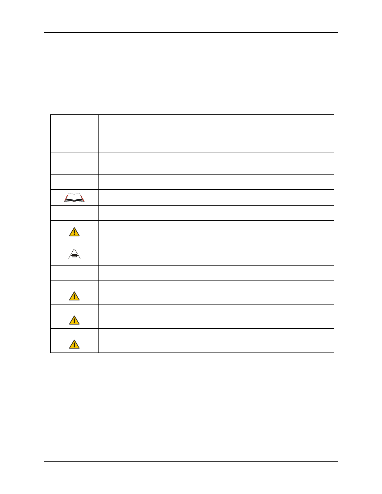
Document Conventions 3
Appendix C - MX5X CE .NET 4.2 takes you through the Windows CE .NET 4.2 system setup
and file structure. Also included are the wireless network configuration instructions for the Cisco
and Symbol radios.
Appendix D - Reference Material contains parameter programming charts. It also contains the
Single Application AppLock information and instruction.
Document Conventions
ALL CAPS All caps are used to represent disk directories/folders, file names, and application names.
Menu | Choice
“Quotes” or
Italics
< > Indicates a key on the keypad (for example, <Enter> ).
ATTENTION Keyword that indicates vital or pivotal information to follow.
Note: Keyword that indicates immediately relevant information.
CAUTION
WARNING
Rather than use the phrase “choose the Save command from the File menu”, this guide uses
the convention “choose File | Save”.
Indicates the title of a book, chapter or a section within a chapter (for example, “Document
Conventions” or Document Conventions).
Indicates a reference to other documentati on.
Attention symbol that indicates vital or pivotal information to follow. Also, when marked
on product, means to refer to the manual or user’s guide.
International fuse replacement symbol. When marked on the product, the label includes
fuse ratings in volts (v) and amperes (a) for the product.
Keyword that indicates a potentially hazardous situation which, if not avoided, may result
in minor or moderate injury.
Keyword that indicates a potentially hazardous situation which, if not avoided, could result
in death or serious injury.
DANGER
Keyword that indicates a imminent hazardous situation which, if not avoided, will result in
death or serious injury.
E-EQ-MX5CERG-F-ARC MX5X Reference Guide
Page 22
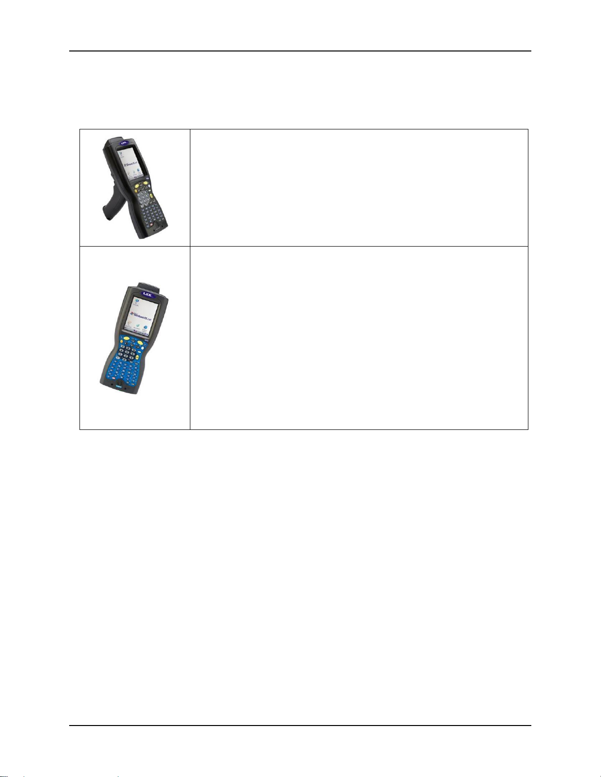
4 Identify Your Device
Identify Your Device
At the front bottom of the MX5X is a label indicating the operating system resident on the mobile
device. This document is one in a series covering the MX5X family of computers:
Label : Windows CE .NET
For MX5X computers equipped with Microsoft Windows CE .NET 4.2 or CE 5
Operating System :
• MX5X User’s Guide
• MX5X Reference Guide
• LXEbook – MX5X User’s Guide (can be downloaded to the MX5X
Label : I-SAFE
For MX5X Intrinsically Safe (MX5-IS) computers equipped with Microsoft
Windows CE .NET 4.2 or CE 5.0 Operating System:
The MX5X Intrinsically Safe Hazardous Location unit (MX5-IS) is distinguished
from the standard MX5X by the blue keypad overlay and the safety approval
labeling on the back of the MX5-IS. Please refer to the MX5X Intrinsically Safe
User’s Guide for cautions, warnings, explanation and instruction when using the
MX5-IS device.
Warning: Standard MX5X units, powered cradles, tethered scanners,
multichargers, headsets, belt battery system, USB devices and external power
supplies are not approved for Hazardous Location use.
device from the LXE Manuals CD.)
• MX5X Intrinsically Safe User’s Guide
• MX5X Reference Guide
• LXEbook – MX5X I-Safe User’s Guide (can be downloaded to the MX5-
IS device from the LXE Manuals CD.)
Figure 1-1 Identify your Device
The following manuals are interchangeable for MX5X computers (except where noted in the
manuals):
• MX5 Cradle Reference Guide
• MX5 Multi-charger Reference Guide
• MX5 Belt Battery System (LXE suggests using this accessory specifically with a Low
Temperature MX5X.)
Do not use the MX5 Belt Battery System with an MX5-IS in a hazardous location.
Note: The External Power Supply for MX5X is not approved for sale in China
MX5X Reference Guide E-EQ-MX5CERG-F-ARC
Page 23

MX5X Features 5
MX5X Features
New features affect user interaction and internal operation of the MX5X.
The appropriate wireless client utility for your device configuration has been pre-installed by LXE
and the utility icon is displayed on the desktop.
Windows CE .NET 4.2 Windows CE 5 Optional?
Summit® Client Utility x x No
Aironet® Client Utility (Cisco) x - No
Symbol® Client Utility x - No
MX5X I-SAFE x x Yes
SE1223 Integrated Laser Scanner x x Yes
SE1224 Integrated Laser Scanner x x Yes
SE2223 Integrated Laser Scanner x x Yes
400MHz x x No
64MB RAM x x No
Type I/II Compact Flash slot x x No
ATA Compact Flash slot x x No
Charging/Communication Cradles x x Yes
Wavelink® Avalanche® Enabler - x Yes
RFTerm® x x Yes
JAVA® x x Yes
Single AppLock x - Yes
Multi AppLock x x Yes
Figure 1-2 Features
E-EQ-MX5CERG-F-ARC MX5X Reference Guide
Page 24
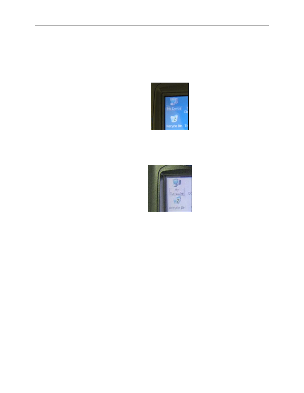
6 Upgrading an MX5X to CE 5.0
Upgrading an MX5X to CE 5.0
Microsoft CE 5.0 Licenses must be purchased from LXE and applied to each upgraded device.
The mobile device cannot be upgraded to CE 5.0 using the Wavelink / eXpress Config application.
Note: The MX5X operating system cannot be upgraded using Wavelink Avalanche.
If your (3.6 inch / 9.1 cm diagonal) MX5 touch screen border looks like this:
It can be upgraded to Windows CE 5.0.
If your (3.8 inch / 9.6 cm diagonal) MX5X touch screen border looks like this:
The device must be returned to LXE for upgrading to CE 5.0, or an LXE Field Service Engineer
can be dispatched to upgrade the hardware and software. Contact your LXE representative for
assistance.
MX5X Reference Guide E-EQ-MX5CERG-F-ARC
Page 25
MX5X Hazardous Location Device 7
MX5X Hazardous Location Device
Label : I-SAFE
Environmental Specifications
Operating Temperature -6°F to 140°F (-21°C to 60°C) [non-condensing]
Storage Temperature -60°F to 160°F (-51°C to 71°C) [non-condensing]
Rating IEC IP67
Operating Humidity 5% to 90% non-condensing at 140°F (60°C)
Vibration Based on MIL Std 810F
Read Before Use
DO NOT USE THIS UNIT IN CLASSIFIED AREAS UNSUITABLE FOR ITS SAFETY
RATINGS.
US and Canadian Approval
Per the Class / Division Classification System, this
unit is rated for safe use in the following classified
locations:
The following symbol is used to identify and warn against specific hazards, and for accident prevention purposes:
CSA C22.2 No. 213-M1987 Non-Incendive Electrical Equipment for Use in Class I, Division
2 Hazardous Locations
Class I
Division 2
Groups A, B, C, D
300° C (T2)
-21°C to +60° C (-6°F to 140°F)
T
amb
Safety Alert Symbol with Keyword Definition and Meaning
Warning
Warning
Warning
Warning
Warning
Caution
Warning
To prevent ignition of a hazardous atmosphere, batteries must only be charged or changed
in an area known to be non-hazardous.
Explosion hazard – Do not disconnect while circuit is live unless area is known to be nonhazardous.
Explosion hazard – Equipment not to be connected to a TNV source when used in a Class
I Division 2 area.
Explosion hazard – Substitution of components may impair suitability for Class I,
Division 2, Groups A, B, C, D.
Danger of explosion if battery is incorrectly replaced. Replace only with the same or
equivalent type recommended by the manufacturer.
Inspect enclosure for signs of deterioration such as cracking, warping, swelling or
softening. Do not use in Hazardous (Classified) Locations if there are any signs of
deterioration.
Keyword that indicates a potentially hazardous
situation which, if not avoided, could result in death or
serious injury.
E-EQ-MX5CERG-F-ARC MX5X Reference Guide
Page 26
8 Getting Started
Getting Started
Note: When your MX5X is pre-configured, the wireless client, flash card and scanner are
programmed by LXE to your specifications. The sequence of steps in Getting Started must
also be completed when the MX5X returns from a Cold Reset and when a new OS version
is loaded. The wireless client, flash card, virtual keyboard and scanner parameters may
also need to be reset after a cold reset.
This section’s instructions are based on the assumption that your new system is pre-configured
and requires only accessory installation (e.g. handstrap) and a power source. LXE recommends
that installation or removal of accessories be performed on a clean, well-lit surface. When
necessary, protect the work surface, MX5X, and components from electrostatic discharge.
In general, the sequence of events is:
Windows CE .NET 4.2
MX5X Desktop CE Indication
1. Insert a fully charged battery. (Always put a fully charged battery in the MX5X at the
beginning of the shift or workday.)
2. Connect an external power source to the unit (if available).
3. If the screen does not automatically display, tap the Power key.
4. Press < N > when the message Update Micro/Boot? Y/N (timer countdown) is displayed, or,
5. Calibrate the touchscreen.
After all files are loaded and the Desktop is displayed, adjust audio volume and other parameters if
desired. If needed, change the Time and Date from it’s default value by tapping the Start |
Settings | Control Panel | Date/Time icon.
Windows CE 5.0
1. Insert a fully charged battery. (Always put a fully charged battery in the MX5X at the
2. If the screen does not automatically display, tap the Power key.
3. Calibrate the touchscreen.
After all files are loaded and the Desktop is displayed, adjust audio volume and other parameters if
desired.
If needed, change the Time and Date from it’s default value by tapping the Start | Settings |
Control Panel | Date/Time icon.
let the timer count down.
MX5X Desktop CE Indication
beginning of the shift or workday.)
MX5X Reference Guide E-EQ-MX5CERG-F-ARC
Page 27

Setup the Client and Network 9
Troubleshooting Start-up
Can’t align the screen, change the date/time or
adjust the volume.
RFTerm® opens and runs upon each cold
reset and warm reset.
Touch screen won’t accept stylus taps.
The MX5X seems to lockup as soon as it is
warm booted.
Setup the Client and Network
Prerequisites
AppLock is installed and running on the mobile device.
AppLock restricts user access to the control panels. See
Chapter 6 - AppLock for setup and processing information.
This activity is the default setting for RFTerm. Tap File |
Exit to close the RFTerm application.
Touchscreen may have been disabled or the touchscreen
may require recalibration. Hold down the Power key and
the Orange key for 4+ seconds to warmboot the device.
Force the Start menu to appear by pressing the right arrow
key and the Blue key to access Start button options, then
use the arrow keys to select menu options (e.g. Start |
Settings ).
There may be small delays while the wireless client
connects to the network, Wavelink Avalanche management
of the MX5X startup completes, and AppLock launch
sequences finalize.
• Network SSID or ESSID number of the Access Point
• WEP or LEAP Authentication Protocol Keys
See Chapter 5 - Wireless Network Configuration for complete information.
For Cisco and Symbol radios – See Appendix C – MX5X CE .NET 4.2, Wireless
Network Configuration
E-EQ-MX5CERG-F-ARC MX5X Reference Guide
Page 28

10 Access Terminal Emulation Parameters
Access Terminal Emulation Parameters
RFTerm icon on desktop.
Before you make a host connection, you will, at a minimum, need to know:
• the alias name or IP address (Host Address) and
• the port number (Telnet Port) of the host system
to properly set up your host session.
Make sure the mobile client network settings are configured and functional. If you are connecting
over wireless LAN (802.11b/g), make sure your mobile client is communicating with the Access
Point.
1. From Start | Programs, run LXE RFTerm or tap the RFTerm icon on the desktop.
2. Select Session | Configure from the application menu and select the host type that you require.
This will depend on the type of host system that you are going to connect to; i.e. 3270
mainframe, AS/400 5250 server or VT host.
3. En ter the Host Address of the host system that you wish to connect to. This may either be a
DNS name or an IP address of the host system.
4. Upda te the telnet port number, if your host application is configured to listen on a specific
5. Select OK.
6. Select Session | Connect from the application menu or tap the Connect button on the
To change options such as Display, Colors, Cursor, Barcode, etc., please refer to the RFTerm
Reference Guide on the LXE Manuals CD.
Saving Settings
When returning from a Cold Reset the previously saved (or original if this is the first Co ld Reset)
registry savings are reloaded.
When you want to save the registry without having to reset the MX5X, double-tap the RegSave
file (located in the Windows folder).
The RegSave utility creates the RegTemp.reg registry backup file. The registry is reloaded from
the RegTemp.reg file after a Cold Reset.
The registry save process takes 5 – 10 seconds. It is also saved after each Resume from Suspend
and each time the OK button is tapped in Control Panel applets.
port. If not, just use the default telnet port.
Command Bar. Upon a successful connection, you should see the host application screen
displayed.
MX5X Reference Guide E-EQ-MX5CERG-F-ARC
Page 29
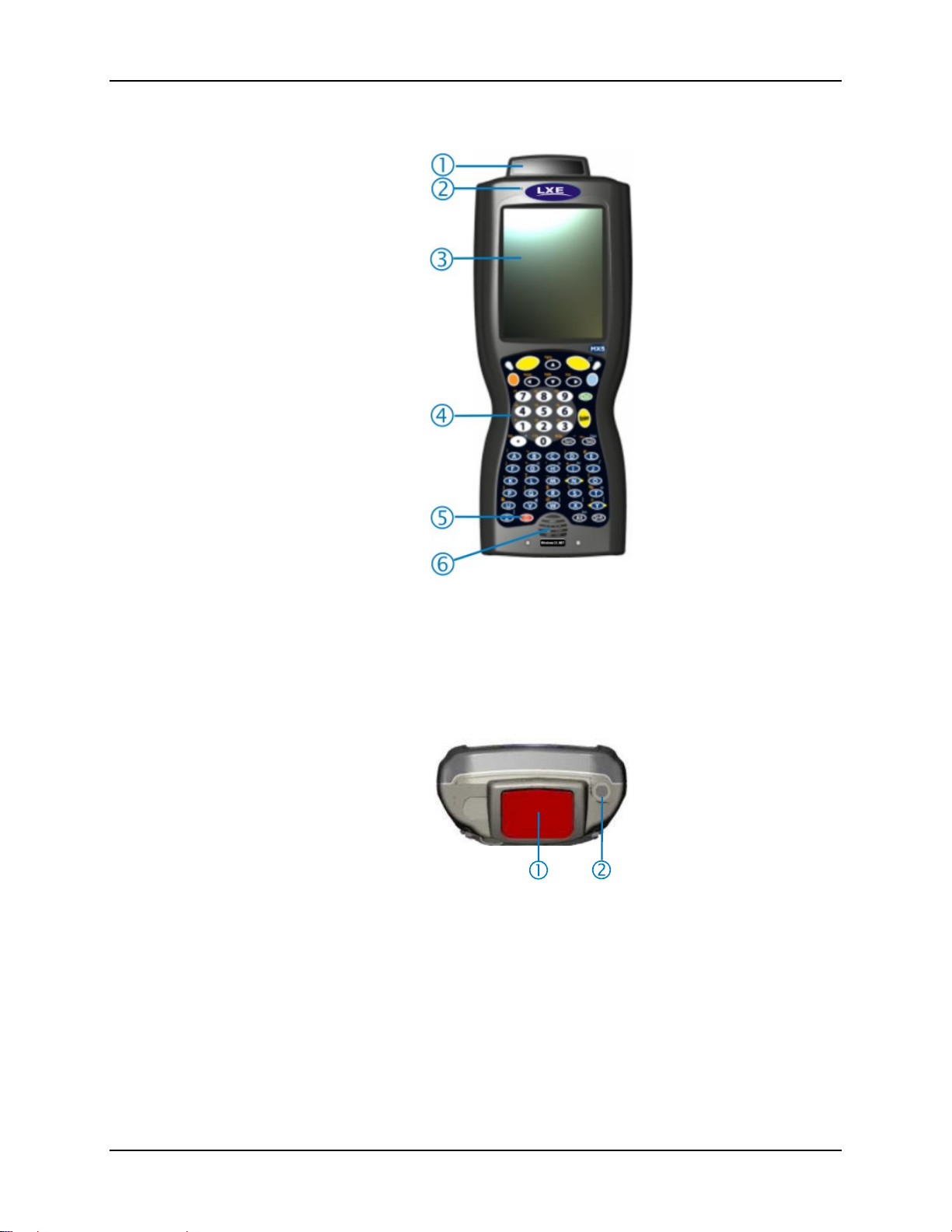
Components 11
Components
Figure 1-3 Front of MX5X
1 Scanner Housing 4 Keypad
2 Microphone 5 Power Key
3 Touchscreen 6 Speaker
Figure 1-4 Scan Aperture and Audio Jack
1 Scan Aperture 2 Audio Jack
E-EQ-MX5CERG-F-ARC MX5X Reference Guide
Page 30
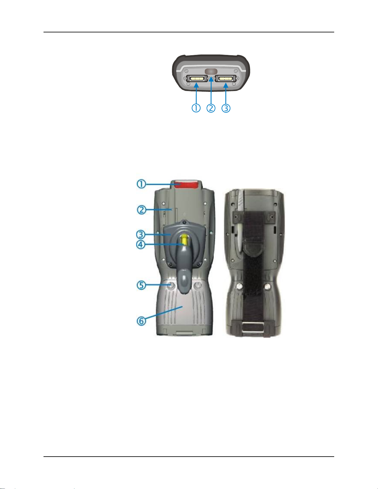
12 Components
Figure 1-5 Ports
1 COM 1 – RS-232, Ethernet, USB and
AC Power Connection
2 COM 3 – IR Port
3 COM 4 – RS-232 and AC Power
Connection
Figure 1-6 Back w/Optional Handle or Hand Strap
1 Scanner 4 Trigger
2 Stylus and Stylus Pocket 5 Battery Fastener
3 Trigger Handle 6 Main Battery
MX5X Reference Guide E-EQ-MX5CERG-F-ARC
Page 31
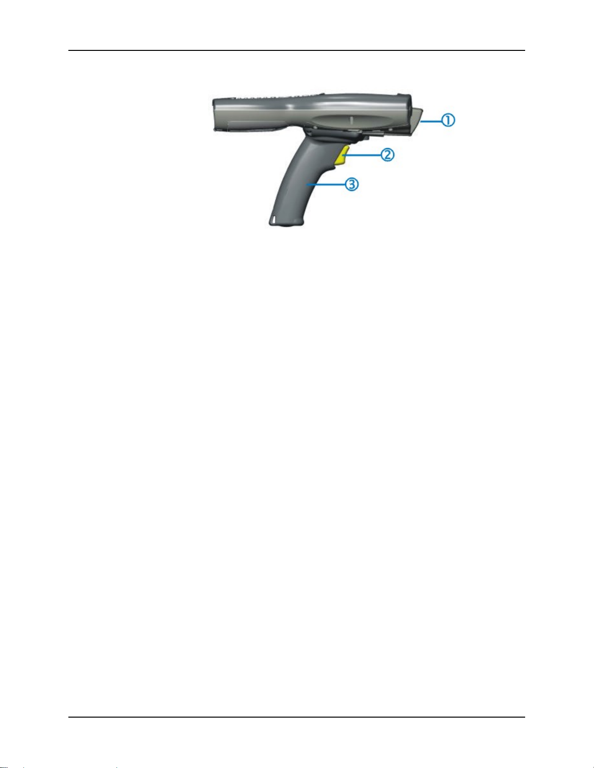
Components 13
Figure 1-7 Handle (Optional)
1 Scan Aperture 3 Handle
2 Trigger
E-EQ-MX5CERG-F-ARC MX5X Reference Guide
Page 32
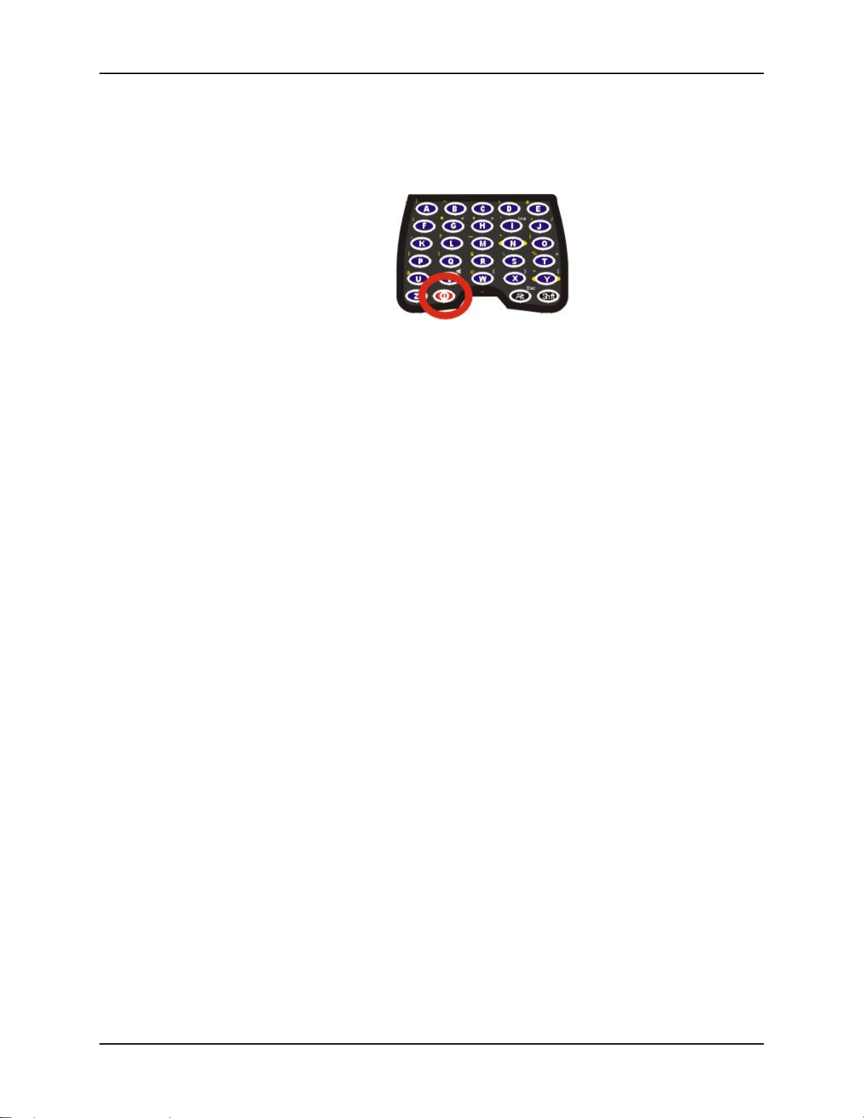
14 Power Key
Power Key
Note: Refer to the section titled Power Modes later in this guide for information relating to the
power states of the MX5X.
Figure 1-8 Power Key Location
The Power key is located next to the < Z > key on the keypad. When a battery is inserted in th e
MX5X for the first time press the Power key.
Tapping the Power key places the MX5X immediately in Suspend mode. Tapping the Power key
again, or connecting to AC power, immediately releases the MX5X from Suspend Mode.
Please refer to the section titled Power Modes later in this guide for a list of the kinds of activities
that will return the MX5X from Suspend Mode.
Please refer to the section titled Power Key in Chapter 2 for Reboot options and instruction.
MX5X Reference Guide E-EQ-MX5CERG-F-ARC
Page 33
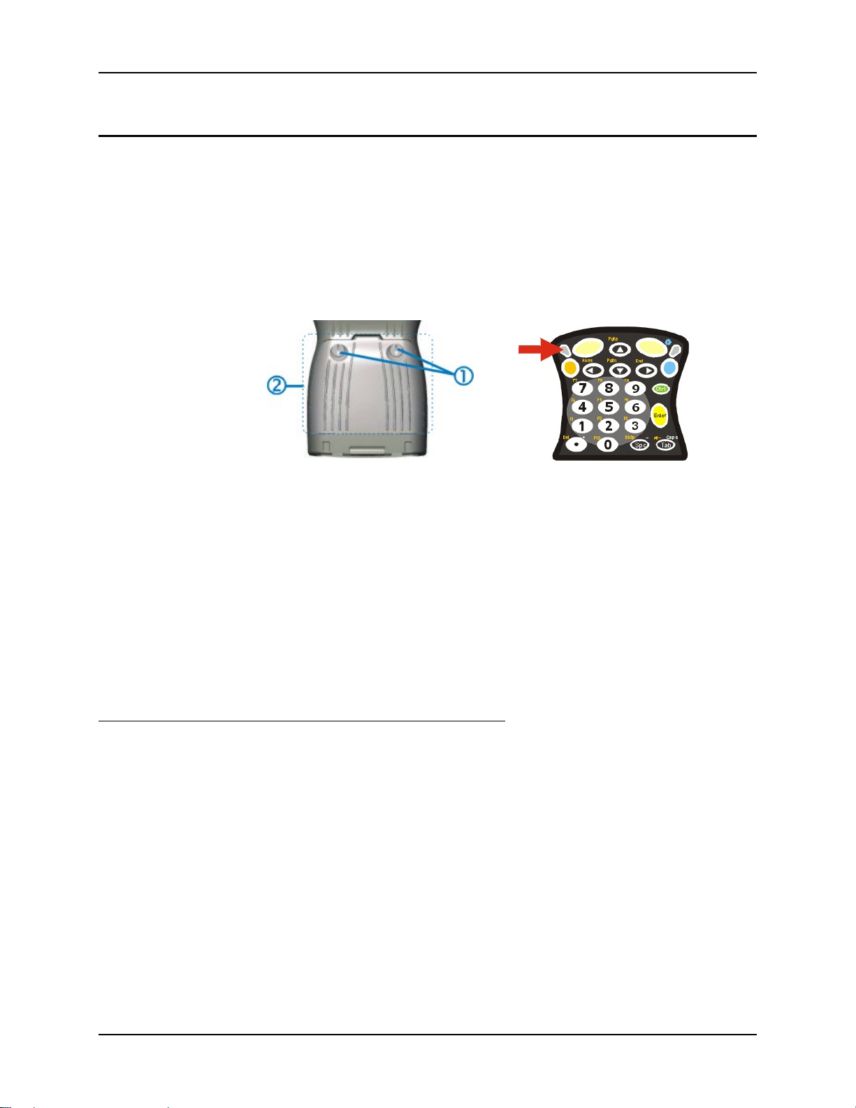
Assembly 15
Assembly
Insert Main Battery
Press the Power key after the battery is inserted into the MX5X.
Note: On first use the MX5X batteries should be charged with an external power source (i.e.
AC Adapter, powered MX5 cradle or MX5 Multi-Charger) – 3 hours for the main battery
and 7 hours for the backup battery. New main battery packs alone must be charged prior
to first use – this process takes up to four hours in an MX5 Multi-Charger.
The MX5X battery compartment is located at the bottom of the back of the mobile device. The
fasteners in the main battery pack are connected to the battery pack.
1 Battery Pack Fasteners 2 Battery Pack
Note: Using the battery removal tool (or a coin) twist each fastener to the left to loosen the
battery pack. Twist the fastener to the right to tighten the battery pack.
Place the battery in the battery well, making sure the tabs on the bottom of the battery pack fit into
the slots at the bottom end of the battery well. Push the battery down into the battery well while
fastening the screws. Fasten the screws tight enough to allow the rubber gasket to create a
watertight seal. If the screws do not easily twist into the threaded opening, remove the battery pack
and repeat the process. When the main battery pack is charging, the Battery Charge LED flashes
green. The backup battery is trickle-charged by the main battery. There is no backup battery
charging indicator. Whenever possible, use the AC power adapter with the MX5X to conserve the
main battery and charge the backup battery.
About Lithium-Ion Batteries
Li-Ion batteries (like all batteries) gradually lose their capacity over time (in a linear fashion ) and
never just stop working. This is important to remember – the MX5X is always ‘on’ even when in
the Suspend state and draws power from the batteries at all times. Tap the Start | Settings | Control
Panel | Power tab to check the battery status and power reading.
The following chart is an approximation. Actual battery capacity will vary based on usage,
ambient temperature and peripherals drawing power from the MX5:
100% capacity 2800 mAh minimum
80% capacity 2240 mAh minimum
Deciding when to put a fully charged main battery pack in the MX5X is difficult to quantify
because it is very application specific. 1800 mAh may be the cutoff for one customer who uses the
computer frequently, while 1000 mAh may be perfectly fine for a customer who occasionally uses
the computer. You need to determine the point at which battery life becomes unacceptable for
your business practices and replace the main battery pack before that point.
Figure 1-9 Main Battery Pack
E-EQ-MX5CERG-F-ARC MX5X Reference Guide
Page 34
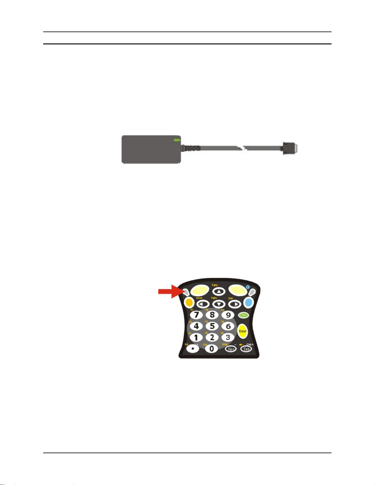
16 Assembly
Connect External Power Supply (Optional)
Note: The External Power Supply for MX5X is not approved for sale in China.
The MX5X receives AC/DC power from the AC/DC 12V Power Supply or a powered MX5
Cradle.
The MX5X DC power connection is located at the base of the MX5X. The cradle power jack is
located on the back of the cradle.
The A/C power cable is not included with the Power Supply, please contact your LXE
representative for replacement power cables. When the power cable is connected to a wall outlet
and the Power Supply, the ON indicator on the Power Supply illuminates green.
Figure 1-10 AC/DC 12V External Power Supply
1. Squeeze the sides of the power connector and push the power cable connector into either
MX5X port. The click means the connector is seated firmly.
2. The CHGR LED above the keypad illuminates when the MX5X is receiving external
power through the power ja ck. The main battery recharges when the MX5X is connected
to an external power source.
Note: When the MX5X is receiving power through a cradle connected to external power the
MX5’s CHGR LED is illuminated.
When the MX5X is connected to an external power supply, and the main ba ttery pack is charg ing,
the Battery Charge LED flashes green.
Figure 1-11 Battery Charging LED
Whenever possible, use the AC power adapter with the MX5X to conserve the main battery and
charge the backup battery.
MX5X Reference Guide E-EQ-MX5CERG-F-ARC
Page 35
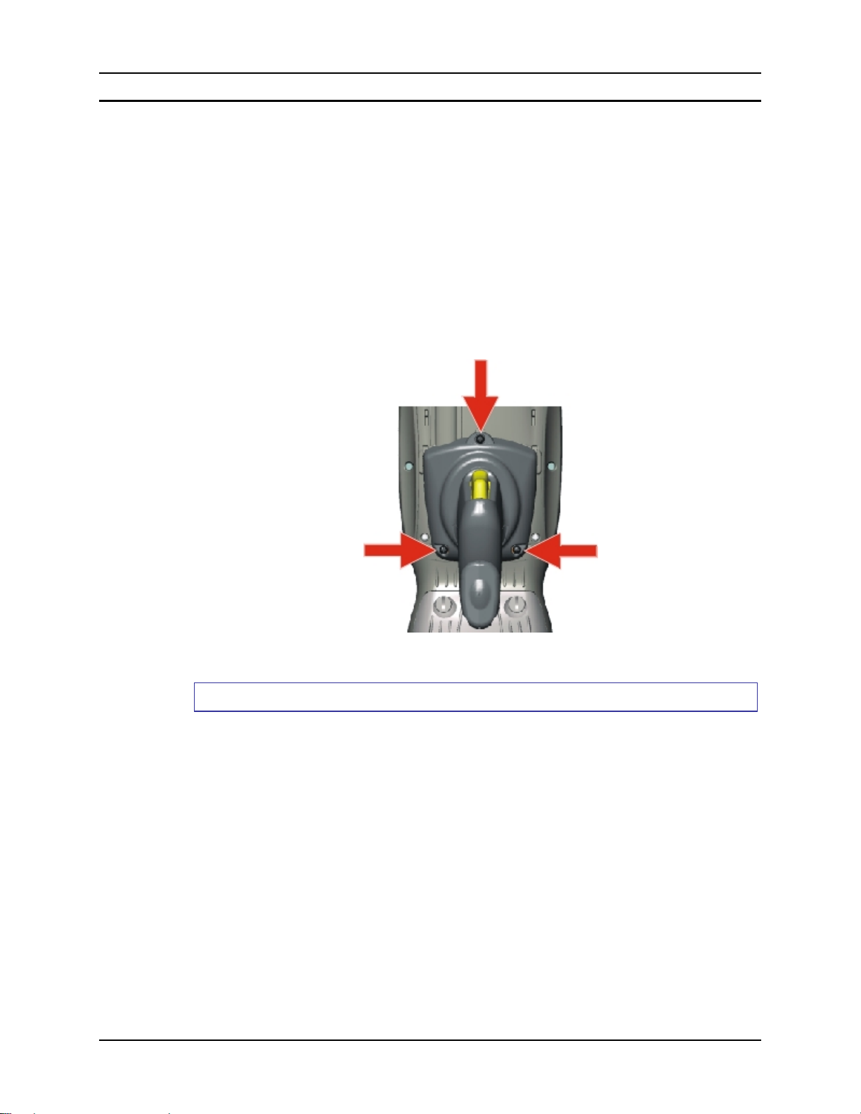
Assembly 17
Install Pistol Grip Handle (Optional)
The MX5X can be purchased with a customer-installable pistol grip handle. The handle enables
the user of the MX5X to hold the unit while pointing and activating the scanner with one hand.
Pressing the trigger activates the scanner and functions the same as the Scan key on the keypad.
With the handle installed the Scan key on the keypad remains active. The trigger duplicates the
operation.
The handle is built of a durable and flexible plastic that will not detach fro m the MX5X if the unit
is dropped.
The trigger handle is a mechanical device. Battery or external A/C power is not required for
operation of the trigger handle. The trigger handle does not need to be removed when replacing
the main battery pack.
Either the trigger handle is attached to the MX5X or the handstrap is attached, not both.
Figure 1-12 Trigger Handle Attach Points
Handle Installation
1. Place the MX5X, with the screen facing down, on a flat stable surface.
2. Slip the L-shaped plastic hooks, at the top of the handle, into the slots on each side of the
back of the MX5X and slide the handle downward until the screw holes are visible.
3. Attach the pistol grip handle to the MX5X (as shown above) with the set of three screws
and washers provided.
4. Test the handle’s connection making sure the MX5X is securely connected.
Periodically check the pistol grip handle for wear and the connection for tightness. If the handle
gets worn or damaged, it must be replaced.
E-EQ-MX5CERG-F-ARC MX5X Reference Guide
Page 36
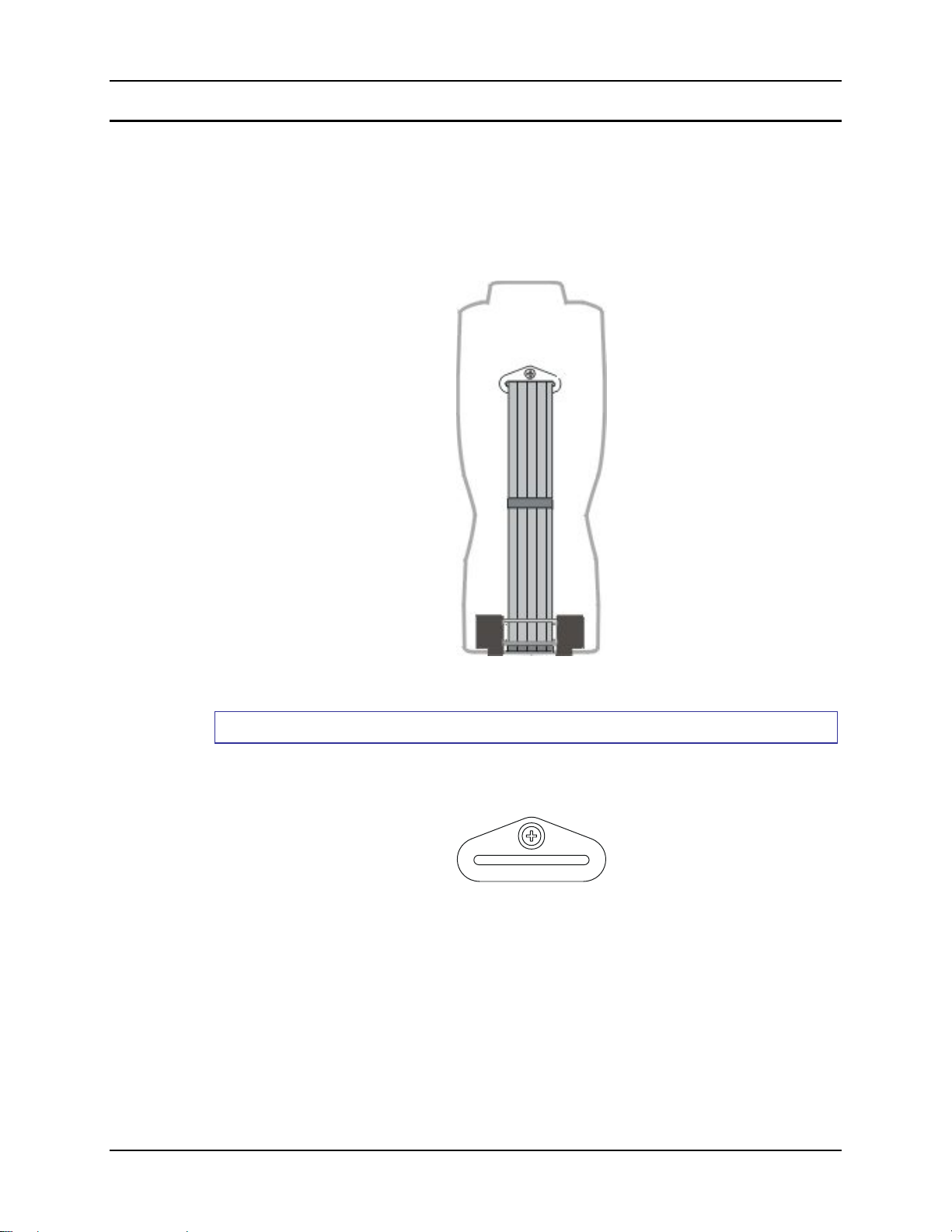
18 Assembly
Install Handstrap
Note: The handstrap cannot be used/installed when the MX5X has the trigger handle installed
at the same time.
An elastic hand strap is available for the MX5X. Once installed, the hand strap provides a means
for the user to secure the computer to their hand. It is adjustable to fit practically any size hand and
is easily moved to allow installation or removal of the MX5X battery pack.
Figure 1-13 MX5X With Handstrap Installed
Installation
1. If a h andle is installed, remove it at this time. See section Install Pistol Grip Handle.
2. Slip the strap through the upper bracket prior to securing the upper bracket to the unit.
Figure 1-14 Upper Strap Bracket
3. When slipping the strap through the bracket make sure the closed loop fastener surface is up.
4. After slipping the strap through the bracket, fold the strap over so that the two closed loop
fastener surfaces mate evenly.
MX5X Reference Guide E-EQ-MX5CERG-F-ARC
Page 37

Assembly 19
Figure 1-15 Strap Inserted in Upper Bracket
5. Prior to secu ring the upper bracket to the unit, slide the bottom assembly into the slots at the
bottom of the MX5X. Insure that both ends of the bottom assembly are securely installed.
6. After securing the bottom of the strap to the MX5X, loosen th e closed loop fastener strap and
then secure the upper bracket to the unit with a screw.
Removal
1. Separate the closed loop fastener tabs and loosen the strap through the upper bracket.
2. Using a Phillips screwdriver, remove the upper bracket screw.
3. Pu ll the bottom assembly from the slots in the bottom back of the MX5X.
Slide the bottom bracket out and away from the MX5X when replacing the main battery pack.
Periodically check the handstrap for wear and the connection for tightness. If the handstrap gets
worn or damaged, it must be replaced.
E-EQ-MX5CERG-F-ARC MX5X Reference Guide
Page 38

20 How To
How To
Tap the Touchscreen with a Stylus
Note: Always use the point of the stylus for tapping or making strokes on the display. Never use
an actual pen, pencil, abrasive or sharp object to write on the touchscreen.
Hold the stylus as if it were a pen or pencil. Touch an element on the screen with the tip of the
stylus then remove the stylus from the screen. Firmly press the stylus into the stylus holder on the
MX5X when the stylus is not in use.
Like using a mouse to left-click icons on a computer screen, using the stylus to tap icons on the
MX5X display is the basic action that can:
• Open applications
• Choose menu commands
• Select options in dialog boxes or drop-do w n bo xes
• Drag the slider in a scroll bar
• Select text by dragging the stylus across the text
• Place the cursor in a text box prior to typing in data or retrieving data using the integrated
barcode scanner or an input/output device connected to the serial port.
• A mouse right-click is performed by holding the stylus down on the touch screen. A circle of
dots appear and then the right-click operation can be performed. See Note.
Note: A ‘right mouse click’ fu nction must be programmed by the customer to accept a constant
stream of left mouse click messages. An application can choose to interp ret th is stream of
messages as a right mouse click. LXE does not support non-LXE application
programming.
An extra or replacement stylus can be ordered from LXE. See the section titled Accessories for the
stylus part number.
Keypad Shortcuts
Use keyboard shortcuts instead of the stylus:.
• Press Tab and a Left or Right Arrow key to select a file.
• Press Shift and an Up or Down Arrow key to select several files. Press Shift+Arrow, then
Shift+Arrow again for each additional file selected.
• Once you’ve selected a file, press Alt then press Enter to open its Properties dialog.
• Press Orange then press numeric dot to delete the currently highlighted file(name). Or, tap and
hold the stylus on the filename and a menu box with a Delete option appears.
Calibrate the Touchscreen
Note: The first time it is used, the MX5X automatically runs the touchscreen calibration
program. The calibration program is also run when Cold Reset is used.
If the MX5X is not responding properly to pen touch taps, the touchscreen may need to be
recalibrated. Contact your System Administrator for assistance.
To recalibrate the screen, tap the Start | Settings | Control Panel | Stylus.
To start, select the Calibration tab then tap Recalibrate. Follow the instructions on th e screen and
press the Enter key to save the new calibration settings or press <Esc> to cancel or quit.
See Also: Chapter 3, section titled Disable Touch and / or Calibration upon Cold Reset.
MX5X Reference Guide E-EQ-MX5CERG-F-ARC
Page 39

How To 21
Set Time Zone (Optional)
Note: The first time it is used, or the device returns from a Cold Reset, the MX5X sets Date and
Time to the factory default values.
To set the Time Zone, tap the Start | Settings | Control Panel | Date/Time icon.
Select the physical time zone. Enable the checkbox next to Automatically adjust clock for daylight
saving if applicable.
Adjust the time and calendar date and tap Apply. Tap OK when you are finished or X to ignore
any changes.
Enter Owner Information (Optional)
Note: Upon initial startup , the MX5X automatically runs th e touch screen calibration p rogram
and the Date/Time dialog.
Use the virtual keyboard or keys on the keypad to enter the following data.
To set Owner information, tap the Start | Settings | Control Panel | Owner icon.
Select the Identification tab, and enter Name, Company, Address, and telephone numbers. Enable
the Display owner identification checkbox if you want this information displayed each time the
system powers on.
Select the Notes tab, enter a note to see at power on. Enable the Display owner notes checkbox to
see the note at power on.
Select the Network ID tab and enter the User Name, Password and Domain.
Tap OK when finished or X to ignore any changes.
Set the Display and Keypad Backlight Timers
Note: Refer to the section titled Power Modes later in this manual for informatio n relating to
the power states of the MX5X.
Select Start | Settings | Control Panel | Display | Backlight tab. Change th e parameter values and
tap OK to save the changes.
The first option affects the MX5X when it is running on battery power only. The second op tion
affects the MX5X when it is running on external power (e.g. AC adapter, powered vehicle or
desktop cradle).
The default value for the battery power timer is 1 minute. The default value for the external power
timer is 10 minutes. The backlight will remain on all the time when both checkboxes are blank.
The transmissive color display backlight timer dims the backlight at the end of the specified time.
E-EQ-MX5CERG-F-ARC MX5X Reference Guide
Page 40

22 How To
Set the MX5X Power Schemes Timers
Note: Refer to the section titled Power Modes later in this guide for information relating to the
power states of the MX5X.
Select Start | Settings | Control Panel | Power | Schemes tab. Change the parameter values and tap
OK to save the changes.
Battery Power Scheme
Use this option when the MX5X will be running on battery power only.
Switch state to Suspend: Default is After 3 minutes
AC Power Scheme
Use this option when the MX5X will be running on external power (e.g. AC adapter, p owered
cradle).
Switch state to Suspend: Default is 5 minutes
Toggle the Display and Keypad Backlight On and Off
When the keypad backlight option is Enabled in Start | Settings | Control Panel | Display |
Backlight tab, both the display and the keypad backlights can be toggled on and off.
Locate the Blue key at the top of the keypad. Toggle the backlights on and off by pressing the
Blue key, then the Right Scan key.
Increase or Decrease Keypad and Display Backlight Intensity
When the backlight is on, press the Orange key and the < 7 > key to decrease the in tensity of the
backlight. Repeating this keypress sequence continues to decrease the intens ity of the backlight
until the backlight is Off.
Once the backlight is off, use the Blue key and the Right Scan button keypress to toggle the
backlight on. This process returns the backlight to it’s brightest intensity.
Connect Audio Jack (Optional)
The MX5X audio jack is located on the top of the unit next to the scan aperture. The internal
speaker is disabled when the audio jack is connected.
Figure 1-16 Connect Audio Jack
Insert the barrel end of the connector into the MX5X audio jack and push in firmly.
Note: The audio option draws power from the main battery.
MX5X Reference Guide E-EQ-MX5CERG-F-ARC
Page 41
How To 23
Set The Audio Speaker Volume
Note: An app lication may override the co ntrol of the speaker vo lume. Turning off sounds saves
power and prolongs battery life.
The audio volume can be adjusted to a comfortable level for the user. The MX5X has an internal
speaker and a jack for an external headset.
Using the Keypad
Note: Start | Settings | Control Panel | Audio must have the options below Enable sounds for
enabled before the following key sequences will adjust the volume.
To adjust speaker volume, locate the < V > key and the Blue key.
Adjust the speaker volume by pressing the:
Blue key, then the <V> key to enter Volume change mode.
Use the Up Arrow and Down Arrow keys to adjust volume until the speaker volume is
satisfactory.
Press the Enter key to exit this mode.
As the arrow keys are tapped, the speaker beeps each time the volume increases or decreases in
decibel range.
Using the Touch Screen
Tap the Start | Settings | Control Panel | Audio icon.
Tabs Actions
System Moving the slider between Soft and Loud adjusts the speaker volume. Enable or
disable sounds for each function by tapping the check boxes.
Routing Use these options to determine where the audio output goes. Enable or disable
the headset and speaker, and microphone gain.
Volume As the volume scrollbar is moved between up and down for System volume, the
computer beeps each time the volume increases or decreases in decibel range.
Extra As the volume scrollbar is moved between up and down, the computer beeps
each time the volume increases or decreases in decibel range for Bay Digital,
CRMA Radio and Mixer volume.
Events Choose sounds to play for Windows CE events or create your own sound
scheme.
Troubleshooting Volume Adjust
Blue+V puts the MX5X in ‘Volume Adjust’ mode.
Shift+Blue+Shift puts the unit in ‘Blue’ Mode which, when followed by ‘V’, puts the unit in
‘Volume Adjust’ mode as well.
If the MX5X is responding to touch input, but does no t respond to keypad (h ard or soft) inpu t, the
MX5X may still be in Volume Adjust mode.
Press Enter to cancel (exit) Volume Adjust mode. After pressing enter, the MX5X should start
responding to key input.
E-EQ-MX5CERG-F-ARC MX5X Reference Guide
Page 42
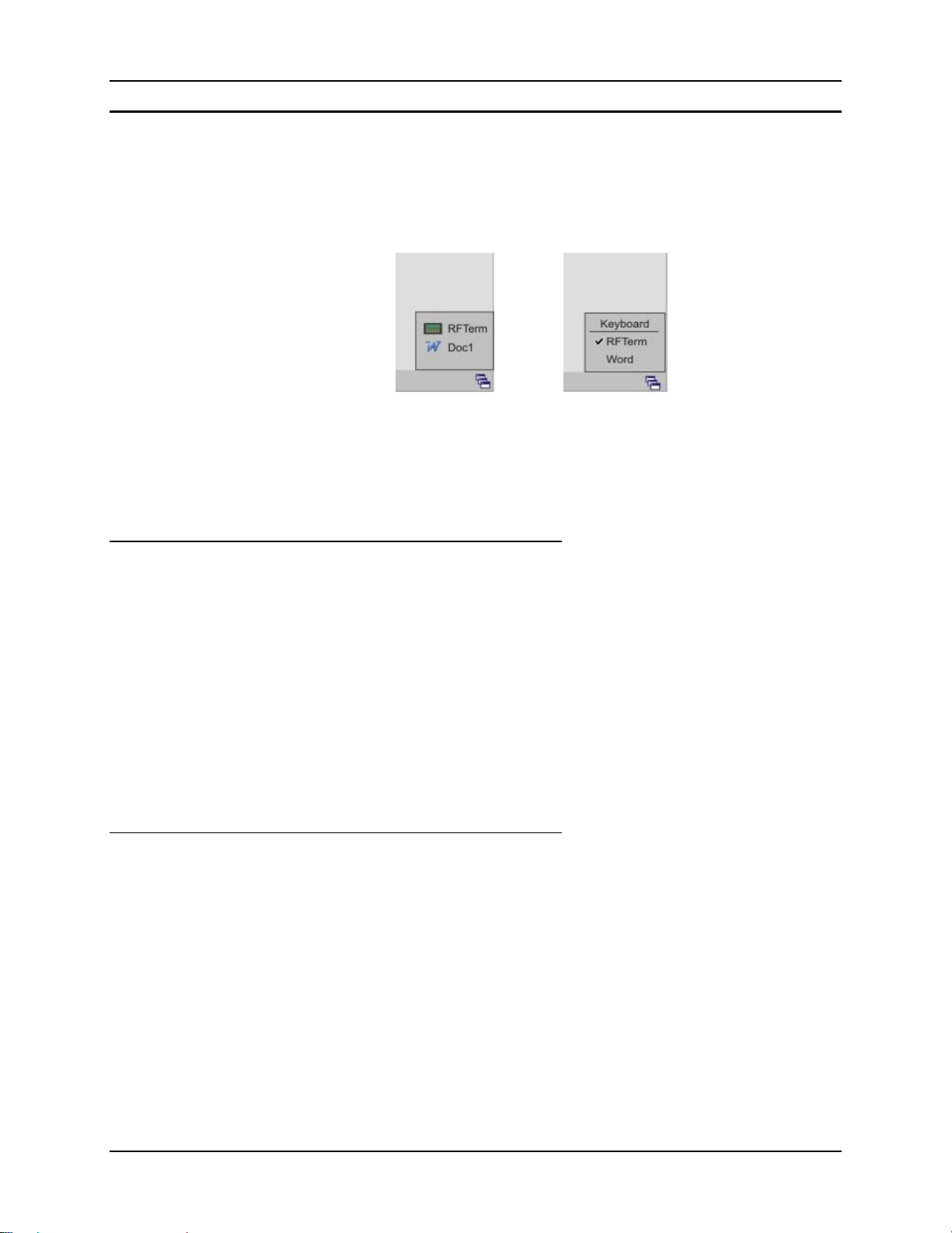
24 How To
Enter the Multi AppLock Activation Key
Note: The touch screen must be enabled. See Chapter 6 - AppLock for AppLock instruction.
AppLock may be installed and running on the mobile device. AppLock restricts access to
programs and the Windows CE Control Panel. Please contact your system administrator for
instruction.
or
Figure 1-17 End-User Multi AppLock Touch Panel Segment
A checkmark indicates applications currently active or available for Launching by the user.
Previous versions used the program icon to indicate the same function. When Keyboard is
selected, the MX5X default input method (Input Panel, Transcriber, or custom input method) is
activated.
Using a Stylus Tap
When the mobile device enters end-user mode, a Switchpad icon (it looks like three tiny windows
one above the other) is visible at the far right in the taskbar. The taskbar is always visible on top of
the application in focus. Note: If only one application is co nfigured and the Input Panel is not
enabled, the Switchpad icon is not displayed.
When the user taps the Switchpad icon, a menu is displayed showing the applications available to
the end-user. They can tap an application name in the popup menu and the selected application is
brought to the foreground (in focus). Th e previous app lication continu es to run in the backgro und.
Stylus taps affect the application in focus only. When the user need s to use the Input Panel, they
tap the Keyboard option. Input Panel taps affect the application in focus only.
The figure shown above is an example and is shown only to aid in describ ing how the user can
switch between applications using a stylus tap. The switchpad lists user applications as well as the
Keyboard option.
Using the Switch Key Sequence
One switch key sequence (or hotkey) is defined by the administrator for the end-user to use when
switching between locked applications. This is known as the Activation key. The Activation key is
assigned by the Administrator using the Global Key parameter (the default Global Key is
Ctrl+Spc). When the switch key sequence is pressed on the keypad, the next application in the
AppLock configuration is moved to the foreground (in focus) and the previous application moves
to the background. The previous application continues to run in the background. End-user key
presses affect the application in focus only.
Note that the system administrator may have assigned a different key sequence to use when
switching applications.
MX5X Reference Guide E-EQ-MX5CERG-F-ARC
Page 43

How To 25
Copy the MX5X LXEbook to the MX5X (Optional)
Note: The LXEbook user guides do not contain the illustrations and regulatory information
contained in the full user guides on the LXE Manuals CD and on the LXE Website. See
the full format user guide MX5X User’s Guide on the LXE Manuals CD.
Mobile Device Required Adobe Acrobat Reader Version
MX5X Windows PDF Viewer (pre-installed by LXE)
First, using your desktop computer download LXEbook – MX5X Users Guide from the LXE
Manuals CD to your desktop computer.
Next, refer to ActiveSync Processes and Initial Install in Chapter 3 of this guide before connecting
the MX5X to your PC.
When the MX5X and the desktop ActiveSync applications are synchronized, tap Explore on the
ActiveSync menu on your PC to display the contents of the MX5X folders.
Then, open the folder on your desktop computer containing the downloaded LXEbook. Tap and
drag the LXEbook to the My Documents folder on the MX5X.
When the file copy process is finished, disconnect the MX5X from the synchronization equipment
and close ActiveSync.
To view the LXEbook on the MX5X, select Start | Programs | PDF Viewer | File | Open. Locate
the LXEbook on the MX5X and ‘open’ the file.
See Also: Install LXEbooks on the LXE Manuals CD.
E-EQ-MX5CERG-F-ARC MX5X Reference Guide
Page 44

26 Enter Data
Enter Data
You can enter data into the MX5X through several different methods. The Scanner aperture
provides barcode data entry, the RS-232 serial port or the IR port are used to input/output data,
and the keypad provides manual entry.
Mobile devices with a touch screen and Microsoft CE software can use a stylus to input data, the
COM ports and/or the keypad. An input panel (virtual keyboard) is available in applications that
expect keyed input.
Keypad Entry
The keypad is used to manually input data that is not collected otherwise. Almost any function that
a full sized computer keyboard can provide is duplicated on the MX5X keypad but it may take a
few more keystrokes to accomplish a keyed task. Please refer to Appendix A – Key Maps for
instruction on the specific keypresses to access all keypad functions.
Almost every key has two or three different functions. The primary alpha or numeric character is
printed on the key.
nd
The Orange or Blue keys are pressed when you want to use a 2
you press a Blue or Orange key (the 2
nd
key), then press the key that has the desired secondfunction key, the second-function key is the ‘active’ key. The specific 2
above the corresponding key in either Orange or Blue.
key function. For example, when
nd
character is printed
Stylus Data Entry
Note: This section is directed to the MX5X daily user. The assumption is tha t the mobile device
The stylus performs the same function as the mouse that is used to point to and click elements on a
desk top computer. The stylus is used in the same manner as a mouse – single tap or double tap to
select menu options, drag the stylus across text to select, hold the stylus down to activate slider
bars, etcetera.
Hold the stylus as if it were a pen or pencil. Touch an element on the screen with the tip of the
stylus then remove the stylus from the screen. The touch screen responds to an actuation force
(touch) of 4 oz. (or greater) of pressure.
The stylus can be used in conjunction with the keyboard and scanner and an input/output device
connected to a serial port.
Touch the stylus to the field of the data entry form to receive the next data feed.
The cursor begins to flash in the field.
The unit is ready to accept data from either the physical keypad, virtual keyboard, integrated
scanner or a scanner connected to the serial port on the cradle, if the scanner applet is configured
correctly.
Note: Always use the point of the stylus for tapping or making strokes on the display. Never use
has been configured and the touch panel calibrated by the System Administrator prior to
releasing the MX5X for daily use. The touch screen should be calibrated before initial
use.
an actual pen, pencil, abrasive or sharp object to write on the touch screen.
See Also: Chapter 3, section titled Disable Touch and / or Calibration upon Cold Reset.
MX5X Reference Guide E-EQ-MX5CERG-F-ARC
Page 45
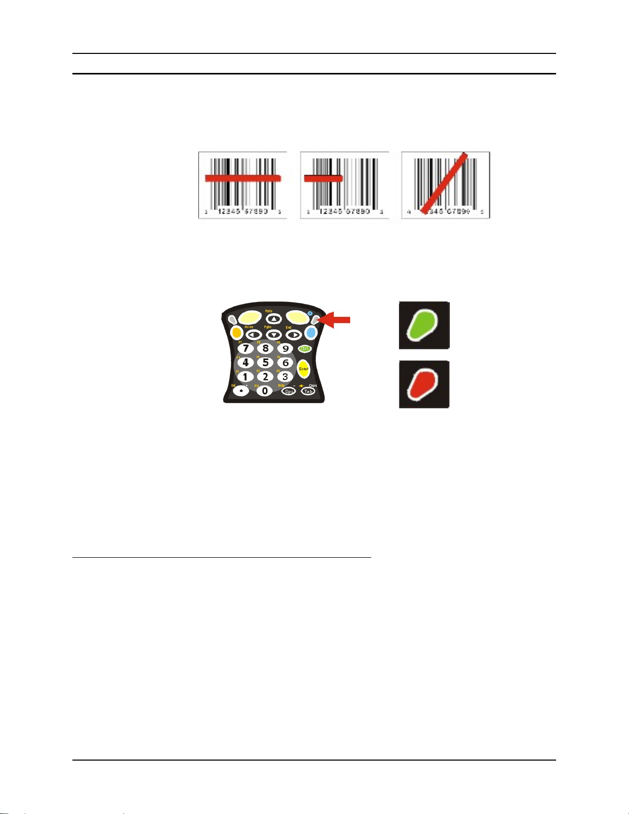
Enter Data 27
Scanner Entry
Read all cautions, warnings and labels before using the laser scanner.
To scan with the laser barcode reader, point the laser window towards a barcode and press the
Scan button. You will see a red laser beam strike the barcode.
Correct Scan Incorrect Scan Incorrect Scan
Figure 1-18 Scan Beam
Align the red beam so that the barcode is centered within the beam. The laser beam must cross the
entire barcode. Move the MX5X towards or away from the barcode so that the barcode takes up
approximately two-thirds the width of the beam.
Green
Red
Figure 1-19 Scanner LED Location
The Scanner Active LED turns red when the laser beam is on. Following a barcode scan and read
the Scanner Active LED turns green for two seconds and the MX5X beeps, indicating a successful
scan. If the scan was unsuccessful, the Scanner Active LED turns off and a different beep
sequence is heard.
The laser engine and Scanner Active LED automatically turn off after a successful or unsuccessful
read. The scanner is ready to scan again after the Scan key (or trigger on the handle if installed) is
released, or after the green LED turns off following a successful scan.
Data Entry and Tethered Scanners
Please refer to the tethered scanner manufacturer’s user gui de for instruction.
E-EQ-MX5CERG-F-ARC MX5X Reference Guide
Page 46
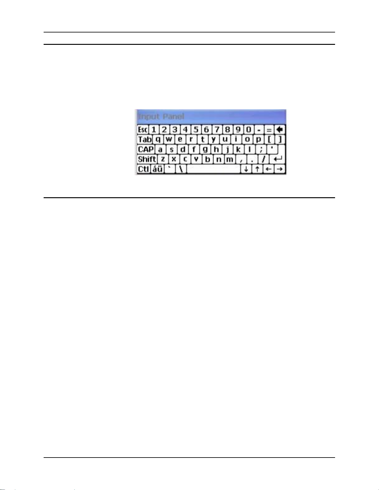
28 Enter Data
Input Panel
The Input Panel is always available. Tap the virtual keyboard icon at the bo ttom of the screen to
put the input panel on the display. Using the stylus:
• Tap the Shift key to type one capital letter.
• Tap the CAPS key to type all capital letters.
• Tap the au key to access symbols.
Figure 1-20 Input Panel
RS-232 Data Entry
The MX5X accepts input from an RS-232 device connected to either RS-232 port.
Note: ActiveSync (running on the desktop computer) will not transfer files over the RS-232
connector on the MX5 cradle IF the scanner port is configured for COM 1 External.
Refer to ActiveSync Processes in Chapter 3 of this guide.
MX5X Reference Guide E-EQ-MX5CERG-F-ARC
Page 47

Getting Help 29
Getting Help
All LXE manuals are now available on one CD and they can also be viewed/downloaded from the
LXE ServicePass or PartnerPass website. Contact your LXE representative to obtain the LXE
Manuals CD.
You can also get help from LXE by calling the telephone numbers listed on the LXE Manuals CD,
in the file titled Contacting LXE. This information is also available on the LXE website’s
ServicePass or PartnerPass page.
Explanations of terms and acronyms used in this manual are located in the file titled LXE
Technical Glossary on the LXE Manuals CD.
Manuals
This document is one in a series covering the MX5X family of computers:
For MX5X computers equipped with Microsoft Windows CE Operating Systems:
• MX5X User’s Guide
• MX5X Reference Guide
• LXEbook – MX5X User’s Guide (can be downloaded to the MX5X device from the LXE
Manuals CD.)
For MX5X Intrinsically Safe (I-SAFE) computers equipped with Microsoft Windows CE
Operating System:
• MX5X Intrinsically Safe User’s Guide
• MX5X Reference Guide
• LXEbook – MX5X I-Safe User’s Guide (can be downloaded to the I-SAFE device fr om the
LXE Manuals CD.)
For both MX5X and MX5 Pocket PC computers, the following are interchangeable (except where
noted):
• MX5 Cradle Reference Guide
• MX5 Multi-charger Reference Guide
• MX5 Belt Battery System (LXE suggests using this accessory specifically with a Low
Temperature MX5X. Do not use the MX5 Belt Battery System with an MX5-IS in a hazardous
location. )
Additional Manuals
• RFTerm Reference Guide
• LXE Security Primer
• CE API Programmer’s Guide
• Integrated Scanner Programming Guide
E-EQ-MX5CERG-F-ARC MX5X Reference Guide
Page 48

30 Getting Help
Accessories
Note: Bluetooth access, Bluetooth modules and Bluetooth Manager are not supported by LXE.
MX5X Standard
Note: Items with a Green letter R in the first column are ROHS-compliant. Please contact your LXE
representative when ordering ROHS-compliant items as the part number may have changed. Items
without the letter R may have received ROHS-compliance after this guide was published.
Holding Accessories
R Strap, Hand, Nylon
Handle, w/wrist strap
R Handle, Neoprene slip-on cover
R Case and strap, MX5X w/o handle
R Case and strap, MX5X w/handle
R Holster, MX5X w/o handle, w/o belt
Holster, MX5X w/handle, w/o belt
R Holster, MX5X w/handle, w/o belt
R Belt, Use with Holsters
Belt, Heater Battery, MX5 (US only)
Charger, Heater Battery Belt, MX5 (US only )
Cable, Heater Battery Belt to MX5, 12” US only (US onl y )
R Cable, Heater Battery Belt to MX5, 1.5M (Non-US)
Miscellaneous
R Stylus, Tethered
R Stylus, 6 Pack Replacement, MX5
R Software, CE .NET 4.2 SDK, MX5 CE
Battery Chargers and Battery
6 Unit Charger w/ US Power Cable
R 6 Unit Charger w/o US Power Cable
R Tool, Battery Removal 5 Pack, MX5
R Battery, Li-Ion
Cradles and Power Supplies
R Vehicle Mount Cradle (Power Adapter Required)
R Standard Desktop Cradle
R Enhanced Desktop Cradle, MX5
R Enhanced Desktop Cradle, Ethernet, MX5X
Power Supply, AC/DC w/ US Power Cable
R Power Supply AC/DC w/o Power Cable
R Power Supply, 12V, Bare Wire Input, MX5X Output
Power Supply, 12V Auto to VM Cradle
R Power Supply, 12V Auto to VM Cradle (EU)
R Power Supply, 24V-72V, Bare Wire Input, MX5X Output
Cables for Cradle and MX5/MX5X Serial Ports
R Cable, MX5 to PC RS-232, D26 to DA9F
R Cable, MX5 to PC USB, D26 to USB
R Cable, MX5 D26 to Ethernet RJ45, MX5X
R Cable, MX5 D26 to USB Host Receptacle, MX5X
MX5A401HANDSTRAP
MX5A406HANDLE
MX5A407HANDLECOVER
MX5A402CASE1
MX5A403CASE2
MX5A404HOLSTER1
MX5A405HOLSTER2
9000A407HOLSTERHAND
9200L67
MX5A382HTRBATTBELT
MX5A383BATTBELTCHGR
MX5A053CBLBATTBELT
MX5A054CBLBATTBELTWW
9000A507STYLUS
MX5A501STYLUS
MX5XA505CENET42SDK
MX5A385CHGR6US
MX5A385CHGR6WW
9000A508BATTERYTOOL
MX5A379BATT
MX5A001VMCRADLE
MX5A002DESKCRADLE
MX5A003EDESKCRADLE
MX5A004ETHDESKCRADLE
MX5A305PSACUS
MX5A305PSACWW
MX5A306PS12V
MX5A380PSAUTO12VUS
MX5A381PSAUTO12VWW
9000A316PS24V72VMX5
MX5A051CBLD26DA9F
MX5A052CBLD26USB
MX5A057CBLETHD26RJ45
MX5A058CBLD26USBHOST
MX5X Reference Guide E-EQ-MX5CERG-F-ARC
Page 49

Getting Help 31
Tethered Scanners (requires 3” D26 to DA9M cable)
R Cable, MX5X for Powerscan, 3”, D26 to DA9M
R Scanner, Powerscan, SR, 8’ Cbl
R Strap with Scanner clip
Scanner, Powerscan, SR, 12’ Cbl
R Scanner, Powerscan, LR, 8’ Cbl
R Scanner, Powerscan, LR, 12’ Cbl
R Scanner, Powerscan, XLR, 8’ Cbl
Scanner, Powerscan, XLR, 12’ Cbl
MX5X ISAFE Device
Note: US and Canada only.
Holding Accessories
R Strap, Hand, Nylon MX5A401HANDSTRAP
R Handle, w/wrist strap MX5A406HANDLE
R Handle, Neoprene slip-on cover MX5A407HANDLECOVER
R Case and strap, MX5X w/o handle MX5A402CASE1
R Case and strap, MX5X w/handle MX5A403CASE2
R Holster, MX5X w/o handle, w/ o belt MX5A404HOLSTER1
R Holster, MX5X w/handle, w/o belt 9000A407HOLSTERHAND
R Belt, Use with Holsters 9200L67
Miscellaneous
R Stylus, Tethered 9000A507STYLUS
R Stylus, 6 Pack Replacement, MX5 MX5A501STYLUS
R Software, CE .NET 4.2 SDK, MX5 CE MX5XA505CENET42SDK
Rubber dust covers for external data ports. Two covers with
R
tether.
Battery Chargers and Battery
6 Unit Charger w/ US Power Cable, 2 Battery Removal To ol s MX5A385CHGR6US
R Tool, Battery Removal 5 Pack, MX5 9000A508BATTERYTOOL
R Battery, Li-Ion MX5A379BATT
Cradles and Power Supplies
R Standard Desktop Cradle MX5A002DESKCRADLE
R Enhanced Desktop Cradle, MX5X (Not IS A FE Ap pr o ved) MX5A003EDESKCRADLE
R Enhanced Desktop Cradle, Ethernet, MX5X MX5A004ETHDESKCRADLE
Power Supply, AC/DC w/ US Power Cable (Not ISAFE
Approved)
Cables for Cradle and MX5/MX5X Serial Ports
R Cable, MX5X to PC RS-232, D26 to DA9F MX5A051CBLD26DA9F
R Cable, MX5X to PC USB, D26 to USB MX5A052CBLD26USB
R Cable, MX5X D26 to Ethernet RJ45, MX5X MX5A057CBLETHD26RJ45
R Cable, MX5 D26 to USB Host Receptacle, MX5X MX5A058CBLD26USBHOST
Note: Use MX5A051CBLD26DA9F or MX5A052CBLD26USB cable for ActiveSync communication
with MX5X cradles.
MX5A055CBL3IND26D9M
8300A326SCNRPWRSR8DA9F
9000A411SCNRSTRAP
8300A327SCNRPWRSR12DA9F
8310A326SCNRPWRLR8DA9F
8310A327SCNRPWRLR12DA9F
8320A326SCNRPWRXLR8DA9F
8320A327SCNRPWRXLR12DA9F
I62-0465-001
MX5A305PSACUS
E-EQ-MX5CERG-F-ARC MX5X Reference Guide
Page 50

32 Getting Help
MX5X Reference Guide E-EQ-MX5CERG-F-ARC
Page 51
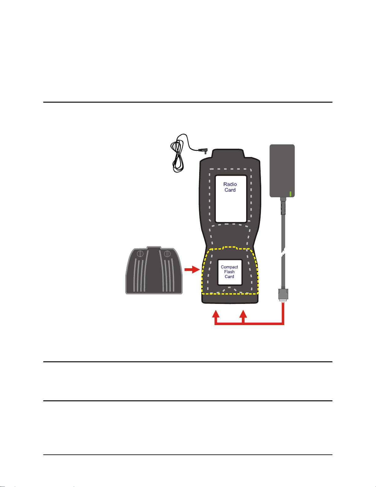
Chapter 2 Physical Description and Layout
Hardware Configuration
System Hardware
The MX5X hardware configuration is shown in the following figure.
Figure 2-1 System Hardware
Note: LXE does not distribute nor support headsets con nected to the MX5X.
Central Processing Unit
The LXE MX5X CPU is an Intel Xscale processor running at 400 MHz. The operating system is
either Microsoft CE .NET 4.2 or Microsoft CE 5.0, resident in flash memory.
Core Logic
The MX5X supports the following I/O components of the core logic:
• One PCMCIA slot (supports Type II PCMCIA cards).
• One compact Flash card slot (supports Type I and II cards) in the rear hatch.
E-EQ-MX5CERG-F-ARC MX5X Reference Guide
Page 52

34 Hardware Configuration
• One ATA compact Flash card slot under the main battery pack.
• One InfraRed port.
• Two serial ports.
• One Digitizer Input port (Touchscreen).
Note: As the MX5X does not have PC Card Management software installed, LXE recommends
purchasing pre-formatted cards.
System Memory
On-board 128MB low power DRAM, 64MB Compact Flash for operating system, 40MB
available for application and data storage.
64MB Flash contains the CE operating system, hardware-specific OEM Adaptation Layer, device
drivers, standard CE applications and utilities. The operating system supports MFC, ATL and
Visual Basic programming languages, TCP/IP and PPP network protocols. The Flash is
configured as the primary boot device.
The computer has one Type I/II CF slot and one ATA CF slot. The MX5X supports and auto
detects up to 256MB of Type I compact flash memory.
Video Subsystem
The touchscreen is a 3/8” (9.65cm) ¼ VGA 240 by 320 pixel TFT Reflective Active Color LCD.
Backlighting is available, can be turned on and off with key sequences. The turn-off timing is
configured through the Start | Settings | Control Panel | Display | Backlight icon. The display
controller supports Microsoft CE graphics modes.
A touch screen allows mouse functions (pointing and tapping on the display or Signature Capture)
using an LXE approved stylus.
The color display is optimized for outdoor use but may also be used indoors. The color display has
a CCFL (Cold-Cathode Fluorescent Lighting) front light.
The transflective display appears to have a greenish hue when the unit is in Suspend.
Power Supply
The LXE MX5X uses two batteries for operation.
A replaceable Lithium-Ion (Li-Ion) 2800mAh battery pack. The battery pack recharges while in
the MX5X with the computer in a powered cradle or with the optional external power source
attached. The main battery pack can be removed from the MX5X and inserted in the MX5 MultiCharger which simultaneously charges up to six battery packs in four hours.
An internal 450 mAh Nickel Metal Hydride (NiMH) coin cell backup battery. The backup battery
is recharged directly by an external power source. Full charging of the backup battery will take
seven hours. The backup battery must be replaced by qualified service personnel.
Connecting the MX5X to an external power source, and a main battery in th e MX5X, is necessary
for backup battery charging.
MX5X Reference Guide E-EQ-MX5CERG-F-ARC
Page 53
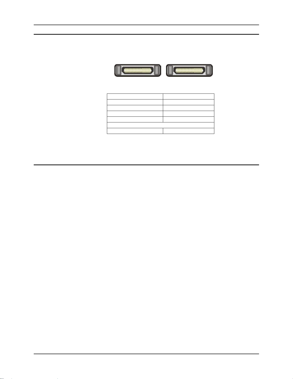
Hardware Configuration 35
COM Ports
The MX5X has two mini D serial ports that are configurable using the Start | Settings | Handheld |
Comms tab:
Figure 2-2 COM Ports – Left and Right
Port 1 (left) COM 1 Port 2 (right) COM 4
USB RS-232
RS-232 AC Power
AC Power
Ethernet
COM 3 is always the IR port.
ActiveSync
Power to the COM ports may be turned on and off.
Note: ActiveSync is not configurable to work on COM 4. IR ActiveSync application is available.
Refer to ActiveSync Processes in Chapter 3 of this guide.
Audio Interface
An interface is available for headset/microphone operation. When the headset is plugged into the
audio port next to the scan aperture, the speaker at the bottom, front of the MX5X is disabled.
E-EQ-MX5CERG-F-ARC MX5X Reference Guide
Page 54

36 Power Key
Power Key
Note: Refer to the section titled Power Modes for information relating to the power states of the
MX5X.
The power key is located next to the < Z > key on the keypad. When a battery is inserted in the
MX5X for the first time, the Power key must be pressed.
Quickly tapping the Power key places the MX5X immediately in Suspend mode. Quickly tapping
the Power key again, or connecting the AC adapter, immediately returns the MX5X from Suspend.
Note: The unit will not suspend on AC power nor when connected through ActiveSync.
Reboot Sequence
Warm Reset
Cold Reset
When the desktop is displayed or an application begins, the power up (or reboot) sequence is
complete. If you have previously saved your settings
Hold down the Power key and the Orang e key for 4+ seconds. A warm reset does not affect the
operating system and no data loss occurs.
Hold down the Power key, the Blue key and the Orange keys for 4+ seconds. The MX5X will
power off, release the keys and the device will power on again.
Calibrating the touchscreen will need to be performed when the MX5X powers on again. See
Chapter 3, section titled Disable Touch and / or Calibration upon Cold Reset.
If needed, change the Time and Date from it’s default values by tapping the Start | Settings |
Control Panel | Date/Time icon.
Important:-- Because of the extreme nature of the Cold Reset, LXE recommends that the Cold
Reset be used only as an emergency procedure and the Warm Reset be used as necessary.
LXE recommends the RegSave file be run when configuration changes are made.
Note: When performing a Cold Reset on a device, the system will ask if you want to overwrite
files – LXE recommends selecting No and continuing with the Cold Reset process.
2
, they will be restored on reboot.
If you need to set up the SE1223, SE1224 or SE2223 integrated scanne r barcode reading
parameters, please refer to the Integr at ed Scanner Programming Guide on the LXE Manuals
CD or the LXE ServicePass website.
2
Configuration settings are saved when a configuration applet is exited by tapping OK.
MX5X Reference Guide E-EQ-MX5CERG-F-ARC
Page 55
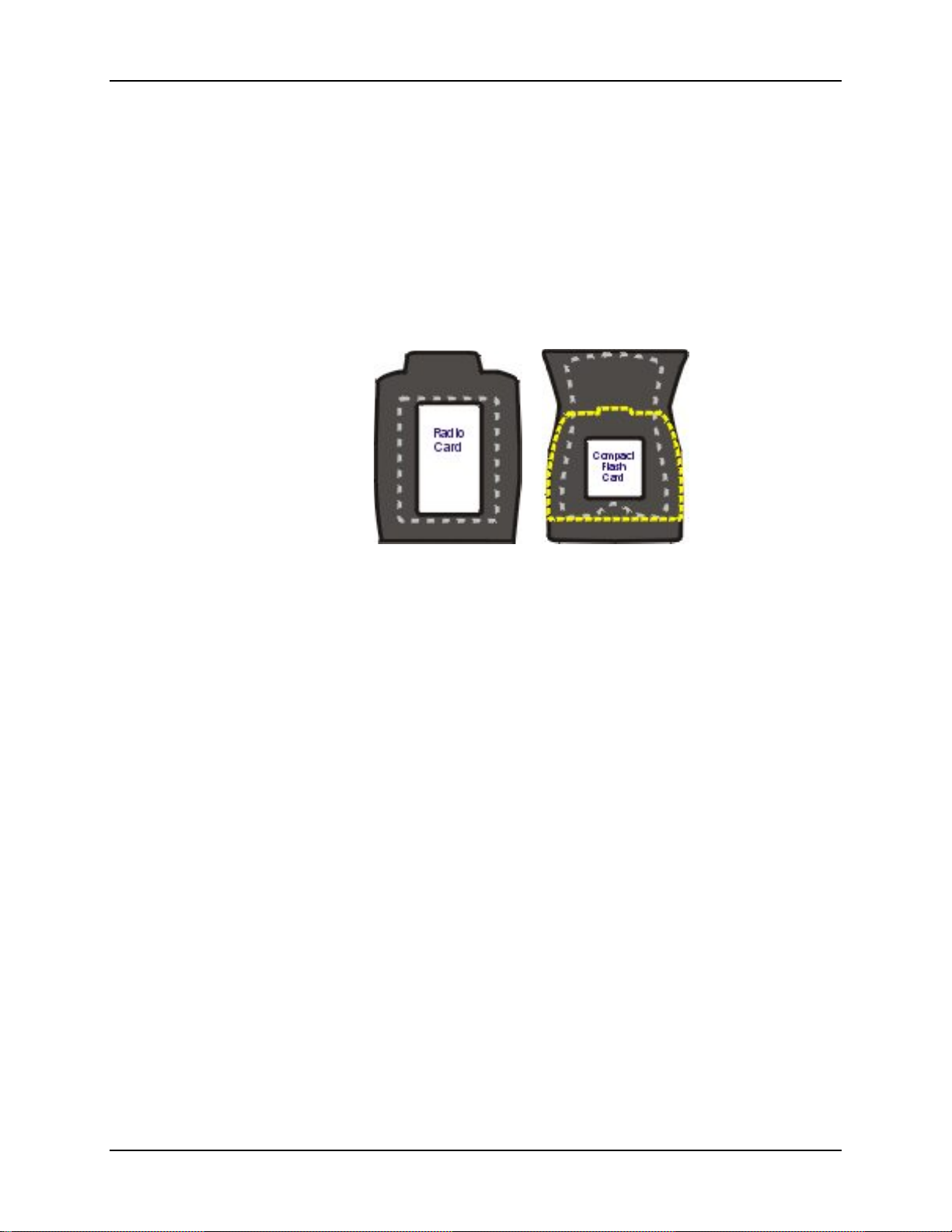
PCMCIA and Flash Cards 37
PCMCIA and Flash Cards
Note: When removing or installing PCMCIA and/or Compact Flash cards, protect the MX5X
internal components from electrostatic discharge.
Use and operation of the Personal Computer Memory Card International Association (PCMCIA)
device (e.g. PC card) is dependent upon both the type of device installed and the application(s)
running on the computer.
Make sure the proper software is pre-loaded and wireless client cards are properly configured.
The compact flash card under the main battery pack is ATA only and is intended to store program
CAB files, MX5X utilities, the registry and the registry backup information.
Figure 2-3 PCMCIA Wireless Client Card and Flash Card Location
Note: As there is no PC Card management software loaded on the MX5X, LXE recommends
purchasing preformatted PC and Flash cards as well as preformatted Compact Flash
disks.
Slot 1
The MX5X has one internal PCMCIA slot that conforms electrically to PCMCIA 2.1
specifications. The PC Slot supplies .75 of an amp at 3V, 5V and for dual 3.3V/5V cards. Battery
voltage is supplied through unused pin 35 to support a WAN wireless client in the slot, if installed.
The PC slot is accessible by the use of a Phillips screwdriver to remove the back hatch of the unit.
It accepts Type II cards only. Slot 0 accepts PCMCIA 2.4GHz wireless client cards.
Note: Care mu st be taken, when reatta ching the back hatch to the device, to preserve the water
tight seal.
Slot 0
The MX5X has one internal compact Flash card port that supports Type I and II CF cards.
The wireless client drivers are stored on the compact flash card in the ATA CF slot (under the
main battery pack). During the cold boot process, the JmpStart program accesses the compact
flash card and loads the wireless client drivers and any saved parameters.
E-EQ-MX5CERG-F-ARC MX5X Reference Guide
Page 56

38 PCMCIA and Flash Cards
Installation / Removal
Equipment required: A screwdriver (not supplied by LXE)
• LXE recommends that installation/removal of cards be performed on a clean, well-lit surface.
• Anti-static protection is required when installing/removing cards. (Not supplied by LXE)
If you anticipate keeping a card out of the MX5X for a long period of time place it in a static-free
storage container. Store in an area that is protected from dirt, moisture, and electrostatic contact.
PCMCIA Cards
Installation
1. Using a screwdriver, loosen the back hatch of the MX5X and carefully remove or loosen all
cables. Disconnect the antenna from the network card.
2. Set both the back and the screws aside.
3. Slid e the PC Card, connector side first, into the slot until it seats. Use caution not to pull or
snag the antenna connector.
4. If the PC Card is difficult to seat in the slot, remove the card, turn it around and re-install.
Flash Cards
Removal
Grasp the top of the PC Card and pull it straight upward to remove.
Use caution not to pull or snag the antenna connector on a network card, if installed .
Installation
Place the MX5X into Suspend. Disconnect the AC adapter from the MX5X.
• ATA CF Card – Loosen then remove the main battery pack.
• Hatch CF Card – Loosen then remove the back cover of the MX5X taking care not to pinch or
twist any cables. Follow the instructions for removing the PCMCIA card, if installed.
Insert the CF card in the recessed slot, label side uppermost.
Replace the main battery pack (or the PC card and back cover of the MX5) and perform a warm
reset. Always perform a warm reset when exchanging one Flash card for another.
Removal
Place the MX5X into Suspend. Disconnect the AC adapter from the MX5X.
• ATA CF Card – Loosen then remove the main battery pack.
• Hatch CF Card – Loosen then remove the back cover of the MX5X taking care not to pinch or
twist any cables. Follow the instructions for removing the PCMCIA card, if necessary.
Carefully lift the CF card up and away from the recessed slot.
MX5X Reference Guide E-EQ-MX5CERG-F-ARC
Page 57

PCMCIA and Flash Cards 39
Accessing the Data on CF and PCMCIA Cards
ATA CF Card
Tap the Start | Programs | Windows Explorer | System folder.
Hatch CF Card
Tap the Start | Programs | Windows Explorer | Storage Card (Storage Card 2 when the PCMCIA
slot is not empty).
Hatch PCMCIA Card
Tap the Start | Programs | Windows Explorer | Storage Card.
E-EQ-MX5CERG-F-ARC MX5X Reference Guide
Page 58
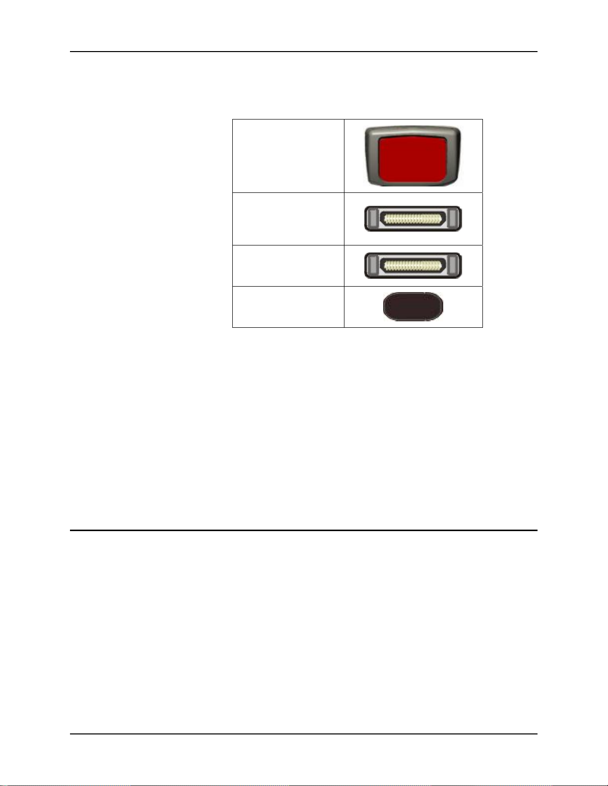
40 COM Ports
COM Ports
The MX5X supports three COM port options.
Scanner Port
RS-232 Port, Ethernet,
USB and AC Power
(COM 1, left)
RS-232 Port, AC Power
USB Port
(COM 4, right)
IR Port (COM 3)
Figure 2-4 COM Ports
COM 1 port is always the left (with screen facing up) RS-232 port on the b ase of the MX5X.
COM 1 port accepts RS-232, USB, USB Host, Ethernet and AC power connectors.
The RS-232 port on the docking cradle is ‘conn ected’ to the MX5X when a tethered scanner is
connected to the RS-232 port on the MX5 cradle, and the MX5X is in the cradle. The cradle must
be powered by an alternate AC or DC power source to enable tethered scanner use.
The COM 3 port is always the IR port on the base of the MX5X.
COM 4 is always the right (with screen facing up) RS-232 port on the base of the MX5X. COM 4
port accepts RS-232 and AC power connectors.
To edit Scanner Com Port parameters, tap the Start | Settings | Control Panel | Scanner. Change the
parameter values and tap OK to save the changes.
An RJ45 Ethernet port is on the Enhanced Desktop Cradle with Ethernet Port.
The USB port requires a DB26 to USB cable (available from LXE). The serial port/USB port also
supports serial data transfer (using a null modem cable) and USB I/O at 1.5 Mbps. The MX5X
automatically detects the cable configuration. Host and client is automatically configured based on
the type of cable used.
Refer to section titled Accessories in this guide for part numbers for the DB26-USB cable and the
null modem cable.
MX5X Reference Guide E-EQ-MX5CERG-F-ARC
Page 59

COM Ports 41
Integrated Scanner Port (Optional)
The MX5X integrated barcode scanner is used to collect barcode data from any nearby compatible
barcode label. Depending on the size of the barcode, size of bars and spacing and quality of the
barcode, the scanner is used to read barcodes between 3 in (7.6 cm) and 30 in (76 cm). The
barcode scanner reads UPC/EAN, Code 39, Code 93, I 2 of 5, Discrete 2 of 5, Code 128, Codabar
and MSI symbologies.
The internal barcode scanner scans only when either Scan button is pressed or the scan trigger is
pressed, if installed. Scan buttons have no effect on tethered barcode scanners connected to the
RS-232 port. The Scanner LED illuminates during any integrated scanner activation.
Look on the label on the back of the MX5X. The type of installed scan engine should be clearly
labeled and may be one of the following:
• Symbol SE 1224 HP
• Symbol SE 1223 LR
• Symbol SE 1223 ALR
• Symbol SE 2223 2D
Use the scanner label information if you need to program the Symbol scanner engine using the
barcodes in the Integrated Scanner Programming Guide (available on the LXE Manuals CD or the
LXE ServicePass website).
Note: Use the scanner control panel to set up using both the integrated scanner and a tethered
scanner.
To switch active scanner Com ports tap the Start | Settings | Control Panel |Scanner | Main tab.
Note: If there is no internal scanner, Internal is greyed out. On units without an internal
scanner, controls on Port 1 and Port 2 are greyed out – the COM1 external control can
be selected.
To assign baud rate, parity, stop bits and data bits to Com 1, tap the Start | Settings | Control Panel
| Scanner | COM1 tab.
If the scanner needs to be configured, refer to the Integrated Scanner Programming Guide on the
LXE Manuals CD.
Tethered Scanners (Optional)
Note: LXE cable numb er MX5A055CBL3IND26D9M must be used with PowerScan® SR, LR
and XLR tethered scanners connected directly to the MX5X device. Do not connect
Symbol® tethered scanners to the MX5X device or to this cable.
The MX5X Scan buttons have no effect on tethered barcode scanners connected to a serial port on
the MX5X or vehicle cradle. Tethered scanners read barcode scans only when the trigger on the
tethered scanner is pressed.
To set the MX5X to use a tethered scanner, tap the Start | Settings | Control Panel | Scanner | Main
tab.
Tap the Send Key Messages (WEDGE) checkbox. The COM port that accepts the scanner data
can be configured for data rate, parity, stop bits and data bits using the COM1 tab.
If the tethered scanner is powered by the mobile device, enable Power Output in Start | Settings |
Control Panel | Handheld | Comms tab.
See Also: Tethered Barcode Scanner Data Entry Using the MX5 Cradle.
E-EQ-MX5CERG-F-ARC MX5X Reference Guide
Page 60
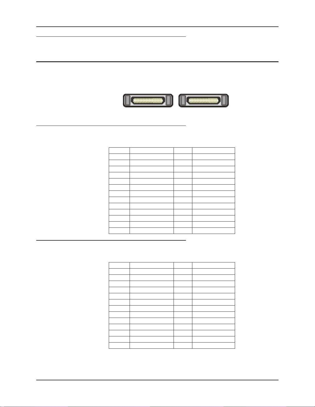
42 COM Ports
Data Entry and Tethered Scanners
Please refer to the tethered scanner manufacturer’s user gui de for instruction.
RS-232 Serial Ports
RS-232 connection is made through an RS-232 serial port. The connector is an industry-standard
RS-232 DB26 female connector. The MX5X automatically detects the cable configuration type.
Figure 2-5 RS-232 Ports
COM1
Cable connections: RS-232, Ethernet, USB and AC Power.
PIN SIGNAL PIN SIGNAL
1 CHG + 14 CHG GND
2 CHG + 15 CHG GND
3 CHG + 16 CHG GND
4 DCD1 17 TPO +
5 RX1 18 TPO 6 TX1 19 GND
7 DTR1 20 TPI +
8 DSR1 21 VCCOUT2
9 RTS1 22 TPI -
10 CTS1 23 RI_VCCOUT1
11 SHIELD 24 SHIELD
12 USB +5V 25 USB COM
13 USB + 26 USB -
COM4
Cable connections: RS-232 and AC Power.
PIN SIGNAL PIN SIGNAL
1 CHG + 14 CHG GND
2 CHG + 15 CHG GND
3 CHG + 16 CHG GND
4 DCD2 17 NC
5 RX2 18 NC
6 TX2 19 GND
7 DTR2 20 NC
8 DSR2 21 NC
9 RTS2 22 NC
10 CTS2 23 RI_VCCOUT2
11 NC 24 NC
12 NC 25 NC
13 NC 26 NC
Figure 2-6 DB26 RS-232 Pinouts
MX5X Reference Guide E-EQ-MX5CERG-F-ARC
Page 61
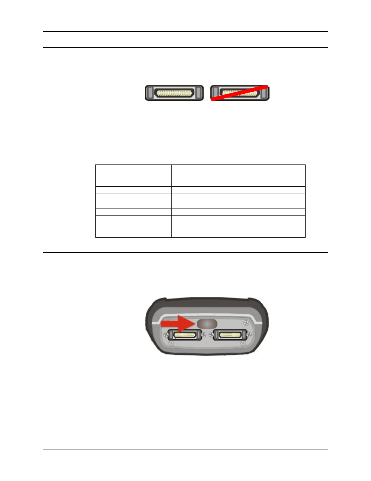
COM Ports 43
USB Port
The USB port (the left port when the MX5X is face up) requires a DB26 to USB cable (available
from LXE). The connector is an industry-standard RS-232 DB26 female connector.
Figure 2-7 MX5X USB Port
The serial port/USB port also supports serial data transfer (using a null modem cable) and USB
I/O at 1.5 Mbps. The MX5X automatically detects the cable configuration. Refer to section titled
Accessories in this guide for part numbers for the DB26-USB cable and the null modem cable.
An optional LXE USB cable is required to adapt the connection to a standard USB connector.
Please refer to section titled Accessories for the USB part number when ordering.
MX5X Cable End Cable Signal USB Cable End
1 Not Used 1 Not Used
2 Not Used 2 From 7
3 To 3 D + (Green Wire) 3 From 3
4 Not Used 4 From 5
5 To 4 Ground (Black Wire) 5 Not Used
6 Not Used 6 Not Used
7 To 2 D – (White Wire) 7 Not Used
8 Not Used 8 Not Used
9 Not Used 9 Not Used
Figure 2-8 USB-Serial Cable Pinouts
IR Port
The InfraRed (IR) port provides a means of transferring information to a device with a similar port
and the proper software. The IR port can be used to communicate with printers or a host computer
with the use of an adapter.
Figure 2-9 IR Port on MX5X
The IR Port is specified as COM 3 and is a bi-directional half-duplex infrared port. It supports the
Slow IrDA (Infrared Data Access) PHY Layer standard that allows communication speeds up to
115k baud.
When sending data through the IR port to another MX5X IR port, make sure both units are in
close proximity to each other. The IR operating envelope has a distance range of 2 cm (0.79
inches) to 15 centimeters (6 inches) with a viewing angle of 30 degrees.
E-EQ-MX5CERG-F-ARC MX5X Reference Guide
Page 62
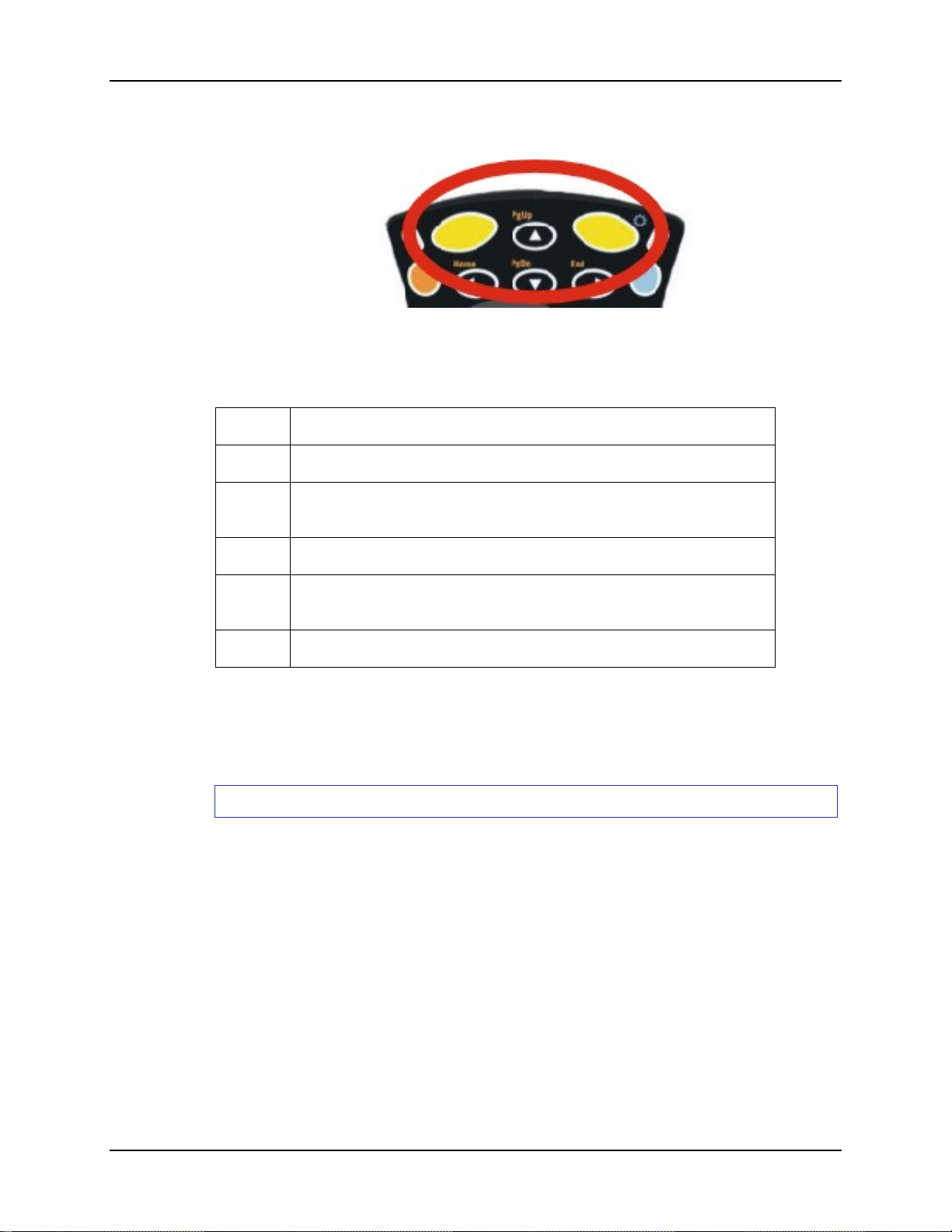
44 Programmable Buttons
Programmable Buttons
Figure 2-10 Scan Buttons
The Scan buttons can be programmed by the System Administrator to perform the following
functions:
Disabled Key press has no effect.
Scan Pressing this key activates the laser scanner.
Enter
Tab Pressing this key moves the cursor to the next input field.
Field
Exit
Esc Pressing this key cancels the current operation.
The default setting for the right button is Enter. The default setting for the left button is Enter.
When the MX5X does not have an integrated scanner, both buttons default to Enter keys and the
Scan selection is greyed out. The buttons can be programmed to perform other functions when
there is no internal scanner.
How To: Program the Scan Buttons
Access: Start | Settings | Control Panel | Scanner | Keys tab
Tap the desired control option. Tap OK to close this menu option. Tap X to cancel changes. Any
changes made are in effect immediately.
Pressing this key confirms a forms entry or transmits information. See the
following section titled Enter Key Function in The Keypad section.
IBM5250/TN5250 units only. Pressing this key exits an input field. See
the following section titled Field Exit Key Function in The Keypad section.
MX5X Reference Guide E-EQ-MX5CERG-F-ARC
Page 63
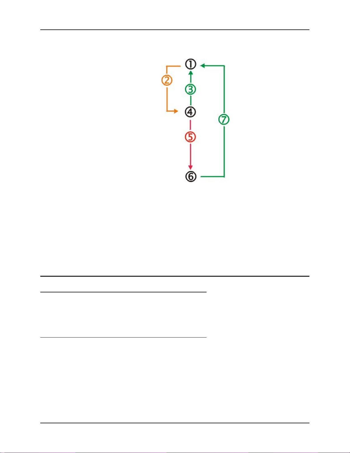
Power Modes 45
Power Modes
On Mode
The Display
The MX5X
Figure 2-11 Power Modes – On, Suspend and Off
1. On
2. Tap Power key or the power has failed
3. Pow e r key or connect to AC power supply
4. Suspend
5. Backup battery and main battery depleted
6. Off
7. Power On
When the display is On:
• the keyboard, touchscreen and all peripherals function normally
• the display backlight is on until the Backlight timer expires
After a new MX5X has been received, a charged main battery inserted, and the Power key tapped,
the MX5X is always On until both batteries are drained completely of power.
When the main battery and backup battery are drained completely, the unit is in the Off mode. The
unit transitions from the Off mode to the On mode when a charged main battery is inserted or
external power is applied.
E-EQ-MX5CERG-F-ARC MX5X Reference Guide
Page 64

46 Power Modes
LED Indicators
LED When On ...
Integrated barcode scanner function.
Scanner Active
Main Battery Charging
Suspend Mode
The MX5X
The Suspend mode is entered when the unit is inactive for a predetermined period of time or the
user taps the Power key.
MX5X Suspend timers are set using Start | Settings | Control Panel | Power | Schemes tab.
A Power key tap wakes the unit and resets the display backlight timers.
Connecting the MX5X to AC power wakes the unit and resets the display backlight timers.
When the unit wakes up, the Display Backlight and the Power Off timers begin the countdown
again. When any one of the above events occurs prior to the Power Off timer expiring, the timer
starts the countdown again.
The MX5X must be placed in Suspend mode before hot-swapping the main battery.
Red – scanning.
Green – good scan.
Left Green LED flashes. When the battery is fully
charged, the green LED remains lit.
Off Mode
The unit is in Off Mode when the main battery and the backup battery are depleted. Insert a fully
charged main battery and press the Power key to turn the MX5X On.
MX5X Reference Guide E-EQ-MX5CERG-F-ARC
Page 65
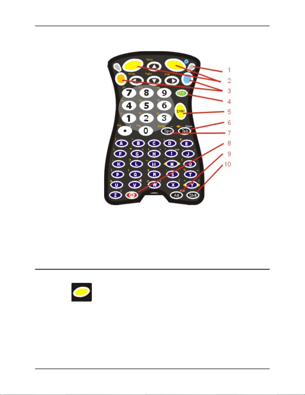
The Keypad 47
The Keypad
1 Scanner Active LED 6 Tab
2 Left and Right Scan 7 Spc
3 Blue and Orange 2
4 Ctrl 9 Alt
5 Enter 10 Shift
The keymaps (keypress sequences) are located in Appendix A – Key Maps.
Scan Key Function
When programmed as Scan keys, either the left or right Scan key activates the scanner. The
internal scanner scans only when the Scan button is pressed (or when the scan trigger is pressed on
the optional trigger handle, if installed).
Figure 2-12 The ANSI / Batch Keypad
nd
Function Key 8 Power On/Off
E-EQ-MX5CERG-F-ARC MX5X Reference Guide
Page 66
48 The Keypad
Enter Key Function
The Enter key is used to confirm a forms entry or to transmit information. How it is used is
determined by the application running on the computer.
2nd Key Function
nd
The Orange (top left) and Blue (top right) keys are 2
keypad. Printed above many keys are small characters, in either orange (on the left side of the key)
or blue (on the right side of the key), that represent the 2
activates the second key function. Note that the 2
time you need to use the 2
nd
function you must press the Orange or Blue 2nd key. To cancel a 2nd
function before pressing another key, press the 2
keys used to activate the 2nd functions of the
nd
nd
nd
key again.
function of that key. Using the 2nd key
key only stays active for one keystroke. Each
Ctrl Key Function
The Ctrl key enables the control functions of the keypad. This function is similar to a regular
keyboard’s Control key. Note that the Ctrl key only stays active for one keystroke. Each time you
need to use a Ctrl function, you need to press the Ctrl key before pressing the desired key.
Alt Key Function
The Alt key enables the alternate functions of the keypad. This function is similar to a regular
keyboard’s Alt key. Note that the Alt key only stays active for one k eystroke. Each time you n eed
to use an alternate function, you need to press the Alt key before pressing the desired key.
Shft Key Function
The Shft key enables the shifted functions of the keypad. This function is similar to a regular
keyboard’s Shift key. Note that the Shift key only stays active for one keystroke. Each time you
need to use a Shifted function, you need to press the Shft key before pressing the desired key.
When the Shft key is pressed the next key is determined by the major key lege nds, i.e., the alpha
keys display lower case letters – when CAPS is On alpha characters are capitalized. For example,
when CAPS is On and the Shft key and the G key are pressed, a lower case g is displayed.
MX5X Reference Guide E-EQ-MX5CERG-F-ARC
Page 67
The Keypad 49
Spc Key Function
The Spc key adds a space to the line of data on the display. This function is similar to a regular
keyboard’s Spacebar. Note that the Spc key only stays active for one keystroke.
Field Exit Function
IBM TN5250 specific keypad only. The left Scan key can be programmed as a Field Exit key. The
Field Exit key is used to exit an input field. If the field is an Auto Enter field, the auto transmit
function is activated. Refer to the Programmable Buttons section for instruction.
Mode Key Functions
Caps Key and CapsLock Mode
This function is similar to a regular keyboard’s CapsLock key. Note that the CapsLock mode stays
active until the CapsLock key sequence is pressed again. Each time you need to use a Caps
function, you need to press the Caps key sequence first. To cancel a CapsLock function press the
Caps key sequence again.
The CapsLock key sequence is Blue key then the <Tab> key.
• No CapsLock AND No Shift keypress – result is a lowercase letter.
• CapsLock OR Shift – result is an uppercase letter.
• CapsLock AND Shift keypress – result is a lowercase letter.
A Capital A is displayed in the taskbar when the device is in CapsLock mode or the Caps Key has
been pressed and the next key (to be capitalized) has not been pressed.
Keypress Sequences
See Appendix A for key maps for all keypads.
Input Panel
The Input Panel is always available. Tap the keyboard icon at the bottom of the screen to put the
input panel on the display. See Input Panel in Chapter 1. If the touch screen has been disabled, the
input panel is not available.
E-EQ-MX5CERG-F-ARC MX5X Reference Guide
Page 68

50 Accessing Files on the Compact Flash Card
Accessing Files on the Compact Flash Card
Double tap My Computer then select System. Files stored on the Compact Flash (CF) card are
listed.
Touchscreen
Figure 2-13 Touchscreen
The MX5X Touchscreen is an Active Color LCD unit capable of supporting QVGA graphics
modes. Display size is 240 x 320 pixels in portrait orientation. The covering is designed to resist
stains. The touchscreen allows signature capture and touch input. A pen stylus is included. The
touchscreen responds to an actuation force (touch) of 4 oz. of pressure (or greater).
The color display has a CCFL (Cold-Cathode Fluorescent Lighting) front light. When the device is
in Suspend mode, the reflective 256 color display appears to have a greenish hue.
The display is automatically turned off when the MX5X enters the Suspend state.
See Also: Chapter 3, section titled Disable Touch and / or Calibration upon Cold Reset.
Display and Keypad Backlight Timer
When the Backlight timer expires the display and keypad backlight is turned off.
The default value for the battery power timer is 1 minute. The default value for the external power
timer is 10 minutes.
The backlight timer dims the backlight on the touchscreen at the end of the specified time and
turns the keypad backlight off. When the display wakes up, the Backlight timers begin the
countdown again.
See the section titled Se t the Display Backlight Timer in Chapter 1 Introduction, section titled
Quick Start.
MX5X Reference Guide E-EQ-MX5CERG-F-ARC
Page 69
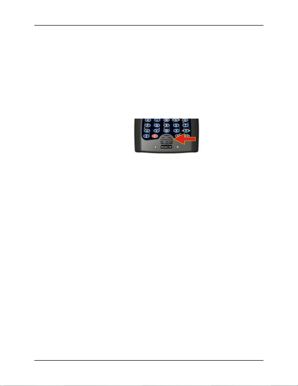
Cleaning the Glass Display/Scanner Aperture 51
Cleaning the Glass Display/Scanner Aperture
Keep fingers and rough or sharp objects away from the scan aperture and display. If the glass
becomes soiled or smudged, clean only with a standard household cleaner such as Windex®
without vinegar or use Isopropyl Alcohol. Do not use paper towels or harsh-chemical-based
cleaning fluids since they may result in damage to the glass surface. Use a clean, damp, lint-free
cloth. Do not scrub optical surfaces. If possible, clean only those areas which are soiled.
Lint/particulates can be removed with clean, filtered canned air.
As the MX5X screen is the same size as commercially available Palm® handheld devices, static
screen protectors that fit the Palm device will also fit the MX5X. Static screen protectors for the
MX5X are not available from or supported by LXE.
Speaker
Figure 2-14 Speaker Location
The MX5X Speaker has a loudness of at least 87 dB (1500 Hz) at 10 cm measured from the front
of the unit. The Speaker volume is adjustable via the keypad or the Settings or by an application
through the use of an API call. There are 5 distinct volume levels. The minimum volume level is 0
(no sound) with a default setting of 3. The volume sticks at maximum and minimum levels.
The speaker is disabled when a headset is plugged into the Audio Jack on the endcap. The audio
volume can be adjusted to a comfortable level for the user. The volume is increased or decreased
one step each time the volume key sequence is pressed.
Speaker volume is first enabled and adjusted using the ‘Audio’ icon. The default value for Audio
is midrange Volume and all sounds enabled. When volume and sounds are enabled, speaker
volume can be adjusted using the volume key sequence, if desired.
Note: An app lication may override the co ntrol of the speaker vo lume. Turning off sounds saves
power and prolongs battery life.
E-EQ-MX5CERG-F-ARC MX5X Reference Guide
Page 70

52 Speaker
Set The Audio / Speaker Volume
The audio volume can be adjusted to a comfortable level for the user. The MX5X has an internal
speaker and a jack for an external headset.
Using the Keypad
Note: Start | Settings | Control Panel | Audio must have the op tions in the Enable sounds for
checked before the following key sequences will adjust the volume.
To adjust speaker volume, locate the <V> key and the Blue key.
Adjust the speaker volume by pressing the:
• Blue key, then the <V> key to enter Volume change mode.
• Use the Up Arrow and Down Arrow keys to adjust volume until the speaker volume is
satisfactory.
• Press the Enter key to exit this mode.
As the arrow keys are tapped, the computer beeps each time the volume increases or decreases in
decibel range.
Using the Touch Screen
Tap the Start | Settings | Control Panel | Audio icon.
Tabs Actions
System Moving the slider between Soft and Loud adjusts the speaker volume. Enable or
Routing Use these options to determine where the audio output goes. Enable or disable the
Volume As the volume scrollbar is moved between up and down for System volume, the
Extra As the volume scrollbar is moved between up and down, the computer beeps each
Events Choose sounds to play for Windows CE events or create your own sound scheme.
Troubleshooting
Blue+V puts the MX5X in Volume Adjust mode.
Shift+Blue+Shift puts the unit in Blue Mode which, when followed by <V>, puts the unit in
Volume Adjust mode as well.
If the MX5X is responding to touch input, but does no t respond to keypad (h ard or soft) inpu t, the
MX5X may still be in Volume Adjust mode.
Press Enter to cancel (exit) Volume Adjust mode. After pressing enter, the MX5X should start
responding to key input.
disable sounds for each function by tapping the check boxes.
headset and speaker, and microphone gain.
computer beeps each time the volume increases or decreases in decibel range.
time the volume increases or decreases in decibel range for Bay Digital, CRMA
Radio and Mixer volume.
MX5X Reference Guide E-EQ-MX5CERG-F-ARC
Page 71

Power Supply 53
Power Supply
The MX5X computer is designed to work with a Lithium-Ion (Li-ion) battery from LXE. Under
normal conditions it should last approximately eight to ten hours before requiring a recharge. The
more you use the scanner or the wireless transmitter, the shorter the time required between battery
recharges.
A suspended MX5X maintains the date and time for a minimum of two days using a main battery
that has reached the Low Warning point and a fully charged backup battery. The MX5X retains
data, during a main battery hot swap, for at least 5 minutes.
Note: New main battery packs must be charged prior to use. This process takes up to four hours
in an LXE Multi-Charger and three hours when the MX5X is connected to external power
through it’s power jack.
Checking Battery Status
Tap the Start | Settings | Control Panel | Power | Status tab. Battery level, power status and charge
remaining is displayed.
Important Battery Information
Important: If the main battery has been out of the MX5X for an extended period of time or
becomes fully discharged or dead, a fully charged backup battery will last for up to 24 hours. If
this happens, the device will cold reset the next time power is applied from either AC power or a
charged main battery. A cold reset will cause loss of data and custom programs. Always store
unused MX5’s with a fully charged main battery pack installed.
Until the main battery and backup battery are completely depleted, the MX5X is always drawing
power from the batteries (On).
New batteries must be fully charged prior to use.
Whenever possible, use the AC power adapter with the MX5X to conserve the main battery and
charge the backup battery.
When a new battery is installed in the MX5X for the first time (or when the backup battery is
completely depleted), the Time and Date must be re-set.
Handling Batteries Safely
Never dispose of a battery in a fire. This may cause an explosion.
Do not replace individual cells in a battery pack.
Do not attempt to pry open the battery pack shell.
Be careful when handling any battery. If a battery is broken or shows signs of leakage do not
attempt to charge it. Dispose of it using proper procedures.
Never place a battery in a pocket or case with keys, coins, or other metal objects.
E-EQ-MX5CERG-F-ARC MX5X Reference Guide
Page 72

54 Power Supply
Caution
Nickel-based cells contain a chemical solution which burns skin, eyes, etc. Leakage from
cells is the only possible way for such exposure to occur. In this event, rinse the affected
area thoroughly with water. If the solution contacts the eyes, get immediate medical
attention.
NiCd and Li-Ion batteries are capable of delivering high currents when accidentally shorted.
Accidental shorting can occur when contact is made with jewelry, metal surfaces,
conductive tools, etc., making the objects very hot. Never place a battery in a pocket or case
with keys, coins, or other metal objects.
Main Battery Pack
The main battery pack has a rugged plastic enclosure that is designed to withstand the ordinary
rigors of an industrial environment. Exercise care when transporting the battery pack making sure
it does not come in contact with excessive heat or any power source other than the LXE MultiCharger or the MX5X unit.
When the main battery pack is properly installed in the unit it provides up to eight hours of
operation depending upon use and accessories installed. The battery pack is resistant to impact
damage and falls of up to four feet to a concrete surface.
Under normal conditions it should last approximately eight hours before requiring a recharge. The
more you use the scanner or the wireless transmitter, the shorter the time required between battery
recharges.
Battery Hot-Swapping
When the main battery power level is low, the MX5X will signal the user with a warning dialog
box on the display and a warning tone. The low battery warning notice and tones continue until
the main battery is replaced, the battery completely depletes, external power is applied to the
MX5X using an AC Adapter, or the MX5X is placed in a powered cradle.
You can replace the main battery by first placing the device in Suspend Mode then removing the
discharged battery (with the battery removal tool) and installing a charged battery within a five
minute time limit (or before the backup battery depletes).
When the main battery is removed, the MX5X remains in suspend mode, the display is turned off
and the backup battery continues to power the unit for at least five minutes. Though data is
retained, the MX5X cannot be used until a charged main battery pack is installed. After installing
the new battery, the MX5X automatically transitions to the On state. Full operational recovery
from Suspend can take several seconds while the wireless client (if installed) is reestablishing an
RF link.
If the backup battery depletes before a fully charged main battery can be inserted, the MX5X will
turn OFF and the Power key must be tapped after a main battery pack is installed.
MX5X Reference Guide E-EQ-MX5CERG-F-ARC
Page 73

Power Supply 55
Low Battery Warning
It is recommended that the main battery pack be removed (with the battery removal tool) and
replaced when it’s energy depletes. When the Low Battery Warning appears perform an orderly
shut down, minimizing the operation of any installed devices and insuring any information is
saved that should be.
When the unit is in an ON state, a low battery warning dialog box appears on the display and a
warning tone is emitted.
Note: Once you receive the Low Battery Warning, you have approximately 5 minutes to
perform an orderly shutdown and replace the main battery pack before the unit powers
off. The Low Battery Warning will transition the mobile device to Suspend before the
computer powers off.
Battery Status LEDs
Main Battery Charging Left GREEN LED slow flashing.
Main Battery Fully Charged Left GREEN LED stops flashing; is solid ON.
Charge / battery fault Left GREEN LED has quick double flashes.
Backup Battery
The MX5X has a backup battery that is designed to provide limited-duration electrical power in
the event of main battery pack failure. The backup battery is a 450 mAh Nickel Metal Hydride
(NiMH) battery that is factory installed in the unit. The energy needed to charge the backup
battery comes from an AC adapter.
It takes several hours of operation before the backup battery is capable of supporting the operation
of the computer. The duration of backup battery lif e is dependent upon operation of the MX5X,
it’s features and any operating applications.
The backup battery is replaced by LXE.
Note: This mobile device’s backup battery maintains it’s charge by drawing power from the
main battery pack. Always store unused devices with a fully charged main battery pack
installed. LXE recommends an in-use mobile device be frequently connected to an
external power source to maintain optimum power levels in the main battery pack and the
backup battery. When the backup battery and main battery pack are dead, the mobile
device reverts to setup defaults when a fully charged main battery pack is installed and
the device is powered On again.
Battery Maintenance Publication
The LXE publication Getting the Most from Your Batteries is available on the LXE Manuals CD
and on the LXE ServicePass website. It is a single-source guide to battery management. The
publication contains information about battery recharging, conditioning, and other pertinent issues.
E-EQ-MX5CERG-F-ARC MX5X Reference Guide
Page 74
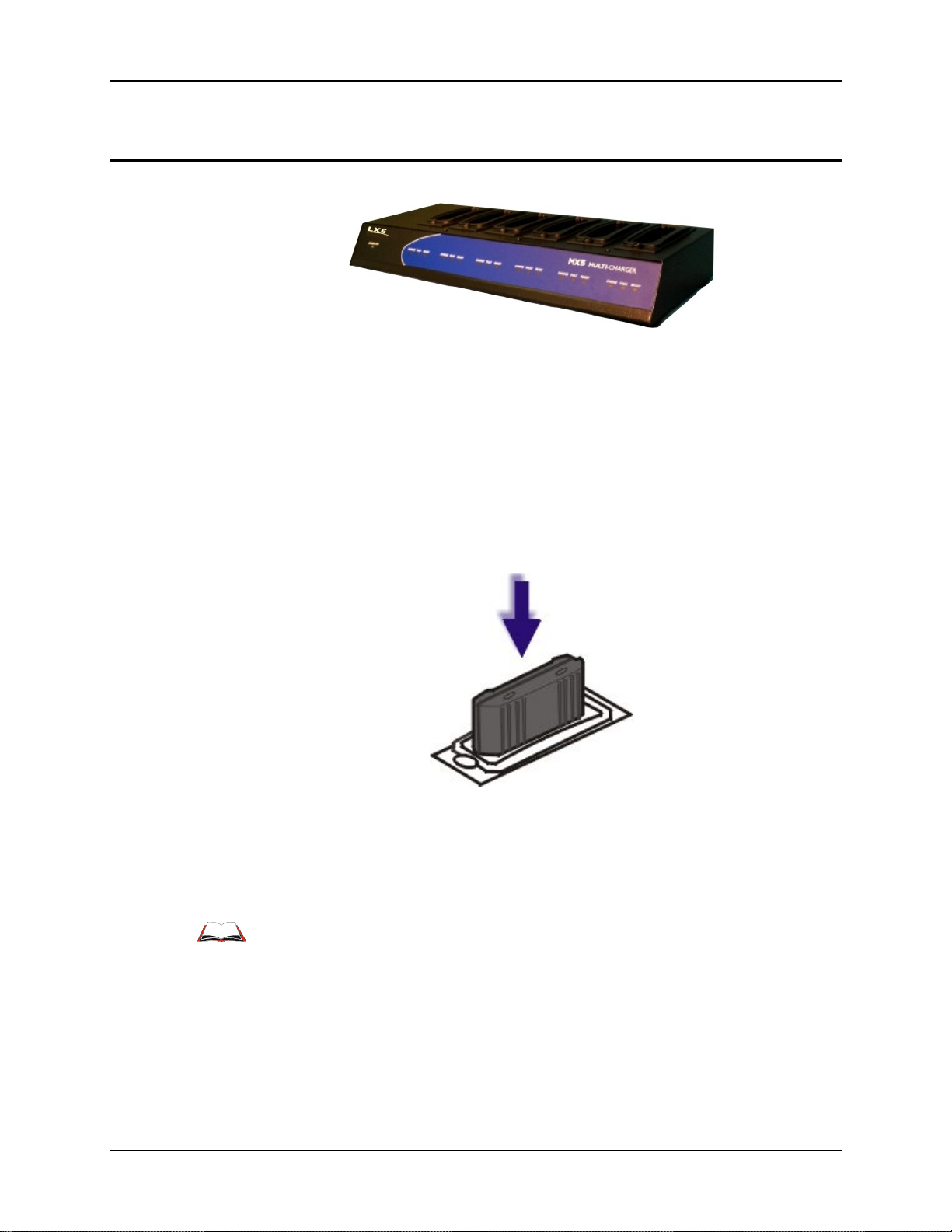
56 Battery Chargers
Battery Chargers
MX5 Multi-Charger (Optional)
Figure 2-15 LXE Multi-Charger
The MX5X main battery pack can be charged in the LXE Multi-Charger.
The main battery pack can be charged in the LXE Multi-Charger. Please refer to the MX5 Multi-
Charger User’s Guide for instruction.
The multi-charger requires an external power source before battery pack charging can commence.
The external Power Supply for the Multi-charger is shipped with the multi-charger.
MX5 Multi-Chargers are not approved for use in Hazardous Locations.
Figure 2-16 Insert Battery Pack in Charging Pocket
Lower the battery pack straight into the battery charger pocket and push it down firmly. Do not
‘slam’ the battery into the charging cup or drop it into the cup.
Failure to follow these instructions can result in damage to the main battery or the charger.
Please refer to the specific battery charger user’s guide for technical information and
operating instructions.
MX5X Reference Guide E-EQ-MX5CERG-F-ARC
Page 75

Battery Chargers 57
External Power Supply for MX5X and Cradle
The MX5X DC adapter can be plugged into either of the D26 pin connectors on the bottom of the
MX5X.
The cradle power jack is located on the back of the cradle.
Figure 2-17 AC/DC 12V Power Supply
Note: When the MX5X is receiving power through a cradle connected to external power the
Battery Charge LED on the MX5X is green.
E-EQ-MX5CERG-F-ARC MX5X Reference Guide
Page 76

58 Cradles
Cradles
MX5 cradles are not approved for use in Hazardous Locations.
Important: The cradles are not designed to secure an MX5X with a protective padded case.
The vehicle cradle is not designed to secure an MX5X with a trigger handle. The desktop cradles
will secure mobile device’s with handstraps or trigger handles.
MX5 docking cradles give the MX5X the ability to communicate with a host computer and other
devices. In addition, using wall AC adapters or DC/DC converters, the cradle charges the main
battery. The MX5X can be either On or in Suspend mode while in the cradles.
LXE offers three desktop cradles and one vehicle cradle:
Standard Desktop Cradle requires AC power before main battery charging can commence.
This cradle does not have an active LED on the front housing. MX5A002DESKCRADLE
Enhanced Desktop Cradle requires AC power before main battery charging can commence. It
will charge both the main battery in the MX5X and another MX5X Battery Pack at the same
time. MX5A003EDESKCRADLE
Enhanced Desktop Cradle with Ethernet Port requires AC power before main battery
charging and host/client communications can commence. It will charge both the main battery
in the MX5X device and another main battery pack at the same time.
MX5A004ETHDESKCRADLE
Vehicle Mount Cradle requires AC/DC power before main battery charging can commence.
MX5A001VMCRADLE
Note: LXE offers a device similar in appearance to the MX5CE device – the LXE MX5 Pocket
PC 2002 device. All MX5 cradles can be used by the MX5s. The Enhanced Desktop
Cradle, developed specifically for the MX5X device, cannot be used by the MX5 Pocket
PC device.
Cradle COM port and power cables are available from LXE. The RS-232 connector is located on
the back of the cradle. When the MX5X is properly docked, the COM 1 RS-232 interface connects
with the DA9 RS-232 port in the cup at the front of the cradle. The cup at the back of the desktop
cradles accept a single Battery Pack for charging.
The Ethernet port is on the Enhanced Desktop Cradle with Ethernet Port.
MX5X Reference Guide E-EQ-MX5CERG-F-ARC
Page 77

Cradles 59
Tethered Barcode Scanner Data Entry Using the MX5 Cradle
The MX5X supports an accessory barcode label reading device (a tethered scanner) connected to
the serial port on a vehicle cradle. Keypad data entries can be mixed with barcode data entries.
Any tethered scanner that decodes the barcode internally and outputs an RS-232 data stream may
be used. It sends the data to the MX5X in ASCII format.
The serial port parameters may need to be changed to match the parameters of the tethered
scanner.
When a tethered scanner is connected to the serial port on a vehicle cradle, the MX5X scanner
must be configured as follows:
1. Start | Settin gs | Control Panel | Scanner | Main | either Port 1 or Port 2
2. Select COM1 External on one of the ports. The tethered scanner must be connected to the
DB9 port on the vehicle cradle. The cradle must be powered by an alternate AC or DC power
source to enable tethered scanner use.
3. If the tethered scanner is powered by the mobile device, enable Power Output in Start |
Settings | Control Panel | Handheld | Comms tab.
See Also: Tethered Scanners (Optional).
The MX5 Cradle Reference Guide contains cradle installation and technical information.
E-EQ-MX5CERG-F-ARC MX5X Reference Guide
Page 78

60 Cradles
MX5X Reference Guide E-EQ-MX5CERG-F-ARC
Page 79

Chapter 3 System Configuration
Introduction
There are several different aspects to the setup and configuration of the mobile device. Many of
the setup and configuration settings are dependent upon the optional features such as hardware and
software installed on the unit. The examples found in this chapter are to be used as examples only,
as the configuration of your specific mobile device may vary. The following sections provide a
general reference for the configuration of the mobile device and some of it’s optional features.
Your MX5X operating system may be Windows CE .NET 4.2 or Windows CE 5.0. This chapter
presents information and procedures for Windows CE 5 only. The MX5X operating system is
displayed on the Desktop. This is the factory default value for the Desktop Display Background.
Windows CE .NET 4.2 information and procedures are contained in Appendix C – MX5X CE
.NET 4.2.
Windows Operating System
For general use instruction, please refer to commercially available Windows CE
5.0 user’s guides or the Windows on-line Help application installed in the mobile
device.
This chapter’s contents assumes the system administrator is familiar with Microsoft Windows
options and capabilities loaded on most standard Windows 2000 (or later) desktop computers.
Therefore, the sections that follow describe only those Windows capabilities that are unique to the
MX5X and it’s Windows CE environment.
Network Configuration
Summit client 2.4GHz network configuration is included in Chapter 5 – Wireless Network
Configuration. Instruction for Cisco and Symbol clients is located in Appendix C MX5X CE .NET
4.2 section titled Wireless Network Configuration.
Installed Software
Note: Some standard Windows options require an external modem connection. Modems are not
available from LXE nor supported by LXE.
When you order a mobile device you receive the software files required by the separate programs
needed for operation and wireless communication. The files are loaded by LXE and stored in
folders in the mobile device. This section lists the contents of the folders and the general function
of the files. Files installed in the mobile device are specific to the intended function of the mobile
device.
Files installed in each mobile device configured for a wireless network environment contain
wireless client specific drivers – the drivers for each type of client are specific to the manufacturer
(e.g. Cisco, Symbol, Summit) for the clients installed in the RF environment and are not
interchangeable.
E-EQ-MX5CERG-F-ARC MX5X Reference Guide
Page 80

62 Installed Software
Software Load
The software loaded on the MX5X computer consists of Windows CE 5.0 OS, hardware-specific
OEM Adaptation Layer, device drivers, Internet Explorer 6.0 for Windows CE browser and
utilities. The software supported is summarized below:
• Operating System -- Full Operating System License: Includes all operating system
components, including Windows CE 5.0 kernel, file system, communications, connectivity (for
remote APIs), device drivers, events and messaging, graphics, keyboard and touchscreen input,
window management, and common controls.
• Network and Device Drivers
• Wavelink Avalanche (Option)
• LXE AppLock (Option)
• Java (Option) -- Java executables and browser components are handled by the Java option
(when installed).
• Terminal Emulation (Option) -- RFTerm (VT220, TN5250, TN3270). Runs automatically at
the conclusion of each reboot (if installed).
• LXE API Routines (see Accessories for the LXE SDK Kit part number)
Note: Please contact your LXE representative for software updates and CAB files as they are
released by LXE.
Software Applications
The following applications are included:
• WordPad (PocketWord in previo us ver s i o ns of Wi nd o ws C E )
• Pocket Inbox
• Word Viewer
• Excel Viewer
• PDF Viewer
• PowerPoint Viewer
• Image Viewer
• Scanner Wedge (LXE developed)
• ActiveSync
• Media Player
• Transcriber
• Internet Explorer
Note that the Viewer applications allow viewing documents, but not editing them.
Note: Bluetooth access, Bluetooth modules and Bluetooth Manager are not supported by LXE.
Optional
AppLock (Option)
Installed by LXE. The AppLock program is accessed by the user or the AppLock Administrator at
bootup or upon completion of a warm boot. Set parameters using the Administration option in the
Control Panel.
See Chapter 6 - AppLock for instruction.
MX5X Reference Guide E-EQ-MX5CERG-F-ARC
Page 81

Installed Software 63
JAVA (Option)
Installed by LXE. Files can be accessed by tapping Start | Programs | JEM-CE. Doubletap the
EVM icon to open the EVM Console. A folder of JAVA examples and Plug-ins is also installed
with the JAVA option. LXE does not support all JAVA applications running on the mobile device.
LXE RFTerm (Option)
Installed by LXE. The application can be accessed by tapping Start | Programs | RFTerm. Please
refer to Terminal Emulation Setup earlier in this guide for RFTerm quick start instruction. Refer to
the RFTerm Reference Guide on the LXE Manuals CD for complete information and instruction.
WAV files added by the user should be stored in System\LXE\RFTerm\Sounds.
Wavelink Avalanche Enabler (Option)
The following features are supported by the Wavelink Avalanche Enabler when used in
conjunction with the Avalanche Manager. Requires Windows CE 5 operating system.
The mobile device cannot be upgraded to CE 5.0 using the Wavelink / eXpress Config / eXpress
Scan application. The device must be returned to LXE for upgrading or an LXE Field Service
Engineer can be dispatched to upgrade the device. Contact your LXE representative for assistance.
After configuration, Enabler files are installed upon initial bootup and after a hard reset. Network
parameter configuration is supported for:
• IP address: DHCP or static IP
• RF network SSID
• DNS hosts (primary, secondary, tertiary)
• Subnet mask
• Enabler update
Related Manual: Using Wavelink Avalanche on LXE Windows Computers.
The MX5X has the Avalanche Enabler installation files loaded, but not installed , on the mobile
device when it is shipped from LXE. The installation files are located in the System folder on CE
devices. The installation application must be run manually the first time Avalanche is used.
After the installation application is manually run, the Enabler begins normal performance. The
Enabler is by default an auto-launch application. This behavior can be modified by accessing the
Avalanche Update Settings panel through the Enabler Interface. The designation of the mobile
device to the Avalanche Manager is LXE_MX5X.
LXE CE devices manufactured before October 2006 must have their drivers and system files
upgraded before they can use the Avalanche Enabler functions. Please contact an LXE
representative for details on upgrading the mobile device baseline.
If the user is NOT using Wavelink Avalanche to manage their mobile device, the Enabler
should not be installed on the mobile device(s).
Terminology may appear different, based on your installed version: Avalanche Manager may be
shown as the Avalanche Mobility Center Console
E-EQ-MX5CERG-F-ARC MX5X Reference Guide
Page 82
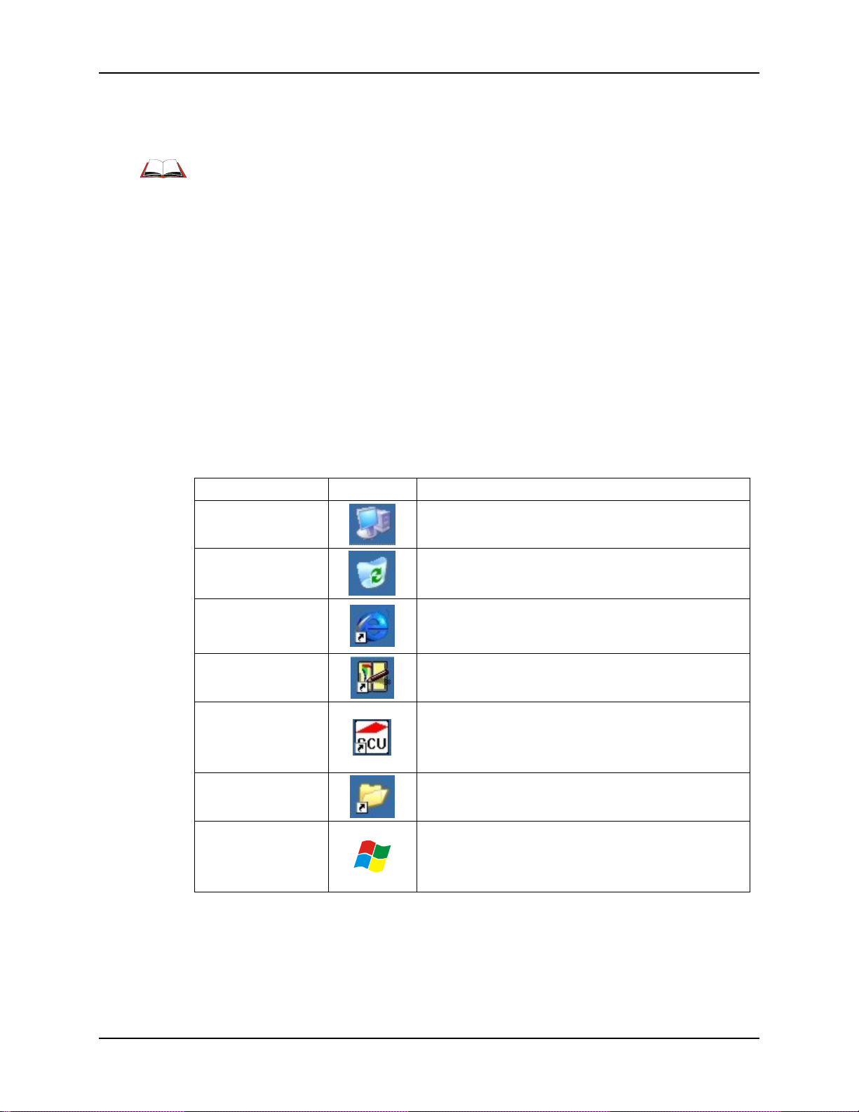
64 Desktop
Desktop
For general use instruction, please refer to commercially available Windows CE 5.0 user’s
guides or the Windows on-line Help application installed in the mobile device.
Note: Whenever possible, use the AC power adapter with the MX5X to conserve the main
battery and to ensure the backup battery is charged.
The Desktop appearance is similar to that of a desktop PC running Windows 2000 or XP. At a
minimum, it has desktop icons that can be tapped with the stylus to access My Computer, Internet
Explorer, and the Recycle Bin.
At the bottom of the screen is the Start button. Tapping the Start Button causes the Start Menu to
open. It contains the standard Windows menu options: Programs, Favorites, Documents, Settings,
Help, and Run.
The Start Menu Shutdown option found on most desktop PC’s has been replaced with a single
command: Suspend, because the mobile device is always powered On (when a fully charged main
battery and backup battery are present).
Tap the Suspend button to turn the screen off or tap the red Power button to turn the screen off and
place the device into Suspend mode.
Tap the screen once more or tap the Power button to ‘wake’ the unit up.
Desktop Option Icon Function
My Device (CE 5.0)
Recycle Bin
Internet Explorer
Transcriber
Wireless Client
Setup Icon (Summit,
Cisco, Symbol)
My Documents
Start
Access files and programs.
Storage for files that are to be deleted.
Connect to the Internet/intranet (requires a wireless
transmitter and Internet Service Provider – ISP
enrollment is not available from LXE).
Enter text using the stylus on the touch screen.
Used for configuring wireless client for network
security settings. Note that only one client can be used
at a time, e.g. if the Summit client icon is present, the
Cisco client icon is not present.
Storage for downloaded files / applicati o ns.
Access programs, select from the Favorites listing,
documents last worked on, change/view settings for the
control panel or taskbar, on-line help, run programs or
place the unit into Suspend mode.
Figure 3-1 Desktop Icons
MX5X Reference Guide E-EQ-MX5CERG-F-ARC
Page 83

Desktop 65
My Device Folders
Folder Description
Application
Data
My Documents
Network Mounted network drive No
Program Files Applications No
System
Temp Location for temporary files No
Windows Operating System in Secure Storage No
Folders Copied at Startup
The following folders are copied on startup:
• System\Desktop -> Windows\Desktop
• System\Favorites -> Windows\Favorites
• System\Fonts -> Windows\Fonts
• System\Help -> Windows\Help
• System\Programs -> Windows\Programs
Preserved upon
Reboot?
Data saved by running applications No
Storage for downloaded files /
applications
Internal SD Flash Card (CAB file
storage)
No
Yes
This function copies only the directory contents, no sub-folders.
The following folders are *NOT* copied on startup:
• Windows\AppMgr
• Windows\Recent
• Windows\Startup
because copying these has no effect on the system, or an incorrect effect.
Files in the Startup folder are executed, but only from System\Startup. Windows\Startup is parsed
too early in the boot process so it has no effect.
Executables in System\Startup must be the actual executable, not a shortcut, because shortcuts are
not parsed by Launch.
E-EQ-MX5CERG-F-ARC MX5X Reference Guide
Page 84
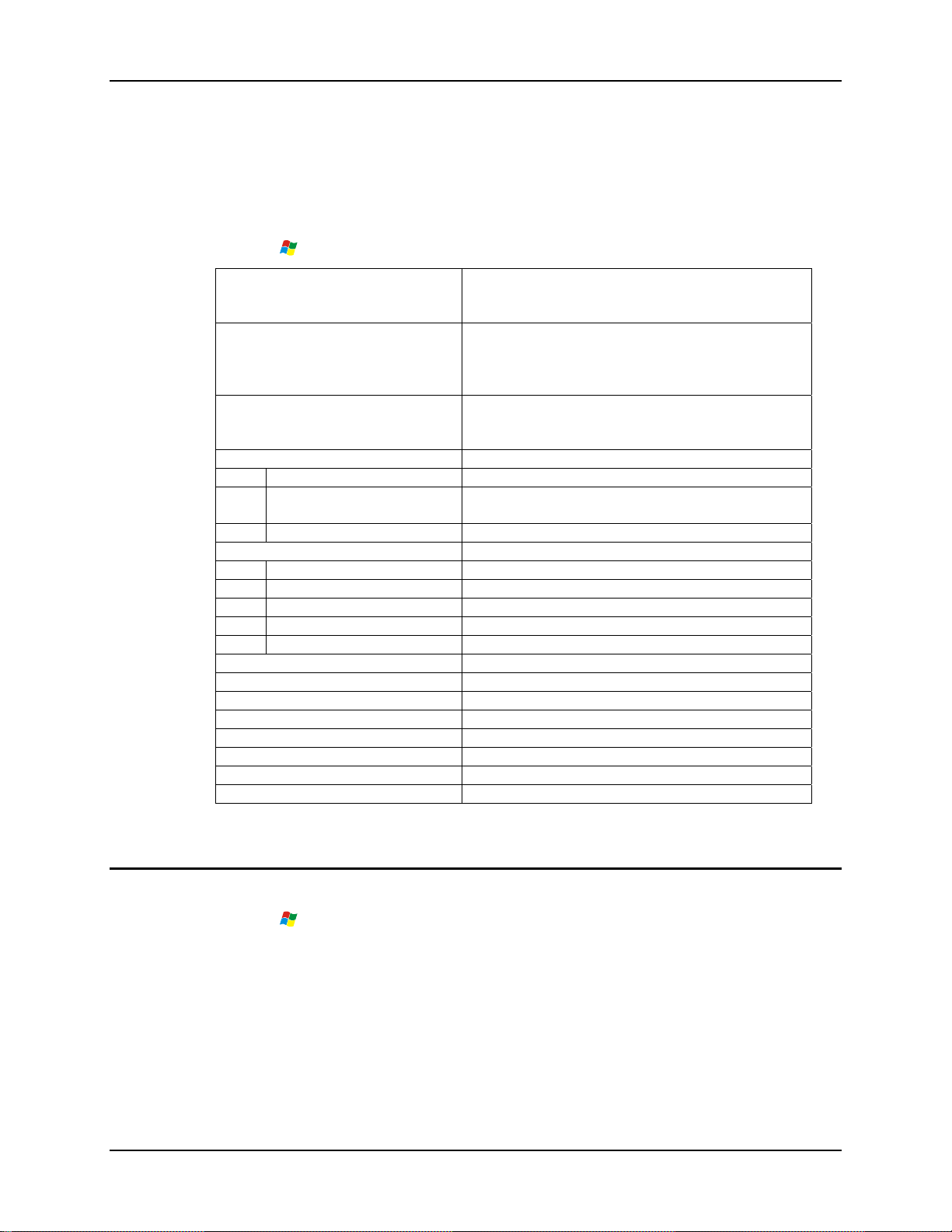
66 Start Menu Program Options
Start Menu Program Options
The following options represent the factory default program installation. Your system may be
different based on the software and hardware options purchased. Note that there can be only one
wireless client installed at a time. The client driver configuration utility chosen is based on the
type of installed wireless client card (Cisco, Summit, Symbol).
Access:
Cisco
Requires Windows CE .NET 4.2
operating system.
Symbol
Requires Windows CE .NET 4.2
operating system.
Summit
Communication Stores Network communication options
Get Connected Run this command after setting up a connection
Remote Desktop Displays MX5X file structure on a remote desktop
Terminal Log on to a Windows Terminal Server
Microsoft File Viewers View downloaded files (see Note)
Excel Viewer View Excel 97 (and later) documents
Image Viewer View BMP, JPEG and PNG images
PDF Viewer View Adobe Acrobat documents
PowerPoint Viewer View PowerPoint files
Word Viewer View Word 97 (and later) and RTF files
Command Prompt The command line interface in a separate window
Inbox Microsoft Outlook mail inbox.
Internet Explorer Access web pages on the world wide internet
iRescue Data backup and recovery utility
Media Player Music management program
Microsoft WordPad Opens an ASCII notepad
Windows Explorer File management program
Transcriber Enter data using the stylus on the touch screen.
| Programs
Set Cisco client / network parameters. (See
Appendix C - MX5X CE .NET 4.2 section titled
Wireless Network Configuration for instruction.)
Tap the Network icon in the toolbar to set up the
Symbol client (See Appendix C - MX5X CE .NET
4.2 section titled Wireless Network Configuration for
instruction.)
Set Summit Client / network parameters. (See
Chapter 5 Wireless Network Configuration for
instruction.)
monitor
Note: The Microsoft File Viewers cannot display files that have been password protected or
encrypted.
Communication
Access: | Programs | Communication
Note: Some communication menu options require an external modem connection to the MX5X.
Modems are not available from LXE nor supported by LXE.
MX5X Reference Guide E-EQ-MX5CERG-F-ARC
Page 85

Start Menu Program Options 67
ActiveSync
Once a relationship (partnership) has been established with Connect (on a desktop computer),
ActiveSync will synchronize using the wireless link, serial port, USB or the infrared port on the
MX5X. Refer to ActiveSync Processes later in this guide.
Note: ActiveSync does not transmit through the IR port in vehicle cradles. It will transport
through the IR port of the MX5 desktop cradles.
For more information about using ActiveSync on your desktop computer, open ActiveSync, then
open ActiveSync Help.
Synchronizing from the MX5X
You must have set up ActiveSync on your desktop computer and completed the first
synchronization process before you initiate synchronization from your device. Refer to ActiveSync
Processes later in this guide.
Get Connected
To initiate synchronization from your device, tap
begin the process.
Note: If you have a wireless LAN card, you can synchronize remotely from your device.
Tap Sync to connect and synchronize. View synchronization status.
Tap Tools to synchronize via IR or change synchronization settings. View connection status.
Tap Stop to stop synchronization.
Tap
| Help for context-sensitive help.
Get Connected is used to initiate a hardwired connection to a host.
The default connect setup is USB direct connect.
After a Connect setup is selected,
connect to a host.
The wireless link is made using
folder. Select
\windows\repllog in the text box.
Before pressing Enter, type a backslash ( / ) and remote in the Run text box. For example:
\windows\repllog / remote
See Also: Cold Boot and Loss of Host Re-connection
repllog.exe and tap the OK button. The Run text box reappears with
| Programs | Communication | Get Connected will start to
| Run. Tap the Browse button and browse to the Windows
| Programs | Communication | ActiveSync to
E-EQ-MX5CERG-F-ARC MX5X Reference Guide
Page 86
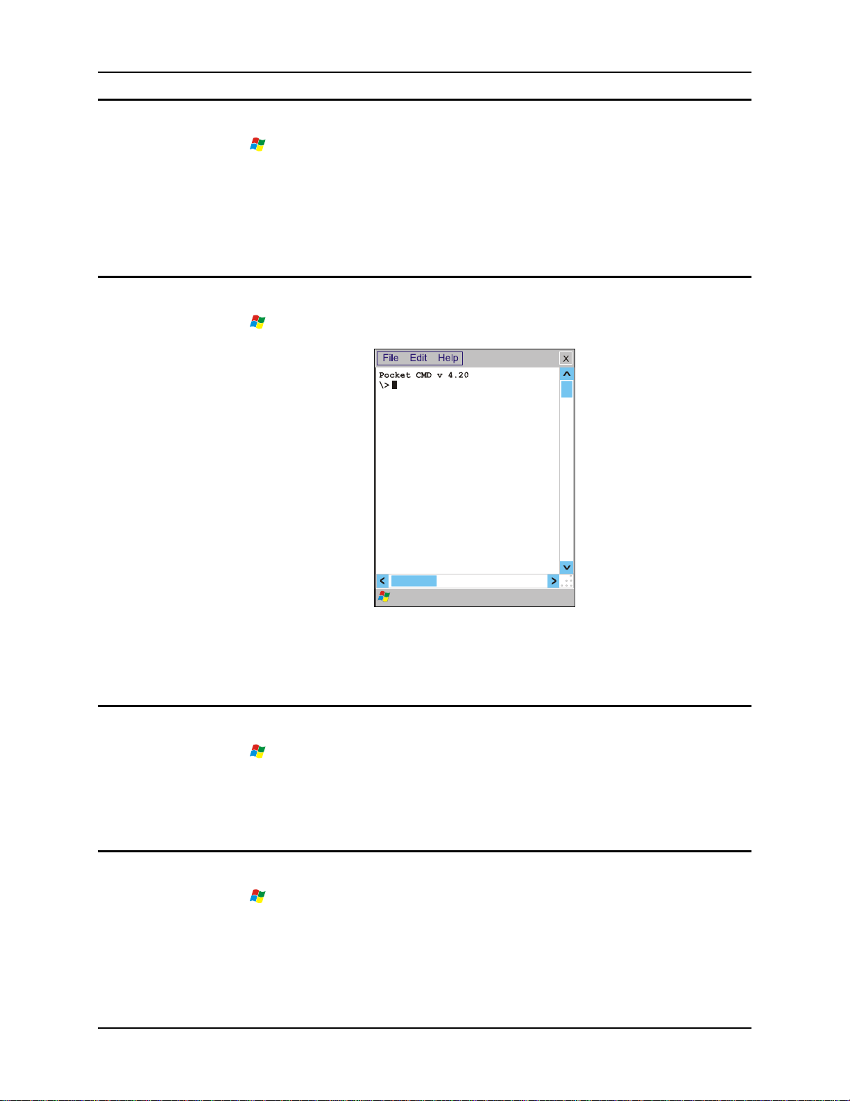
68 Start Menu Program Options
Remote Desktop Connection
Access: | Programs | Communication | Remote Desktop Connection
There are few changes in the CE version of Remote Desktop Connection as it relates to the general
desktop Windows PC Microsoft Remote Desktop Connection options.
Select a computer from the drop down list and tap the Connect button.
Tap the Options >> button to access the General, Display, Local Resources, Programs and
Experience tabs. Tap the <?> button to access Remote Desktop Connection Help.
Command Prompt
Access: | Programs | Command Prompt
Type help at the command prompt for a list of available commands. Exit the Command Prompt by
typing exit at the command prompt or select File | Close.
Inbox
Access: | Programs | Inbox
This option requires a connection to a mail server. There are a few changes in the CE version of
Inbox as it relates to the general desktop Windows PC Microsoft Outlo ok Inbox options. Tap the
<?> button to access Inbox Help. ActiveSync can be used to transfer messages between the MX5X
inbox and a desktop inbox. Refer to ActiveSync Processes in Chapter 3 of this guide.
Internet Explorer
Access: | Programs | Internet Explorer
This option requires a wireless card and an Internet Service Provider. There are a few changes in
the CE version of Internet Explorer as it relates to the general desktop Windows PC Internet
Explorer options. Tap the <?> button to access Internet Explorer Help.
Figure 3-2 Pocket CMD Prompt Screen
MX5X Reference Guide E-EQ-MX5CERG-F-ARC
Page 87

Start Menu Program Options 69
Media Player
Access: | Programs | Media Player
There are few changes in the CE version of Media Player as it relates to the general desktop
Windows PC Microsoft Media Player options. Tap the <?> button to access Media Player Help.
Windows Explorer
Access: | Programs | Windows Explorer
There are a few changes in the CE version of Windows Explorer as it relates to the general
desktop PC Windows Explorer options. Tap the <?> button to access Windows Explorer Help.
Transcriber
Access: | Programs | Transcriber
Select Transcriber on the Start | Programs menu or tap the icon on the Desktop. To make changes
to the Transcriber application, enable or disable the current Transcriber session, etc., tap the hand
with a pen icon in the toolbar. Tap the <?> button or the Help button to access Transcriber Help.
E-EQ-MX5CERG-F-ARC MX5X Reference Guide
Page 88
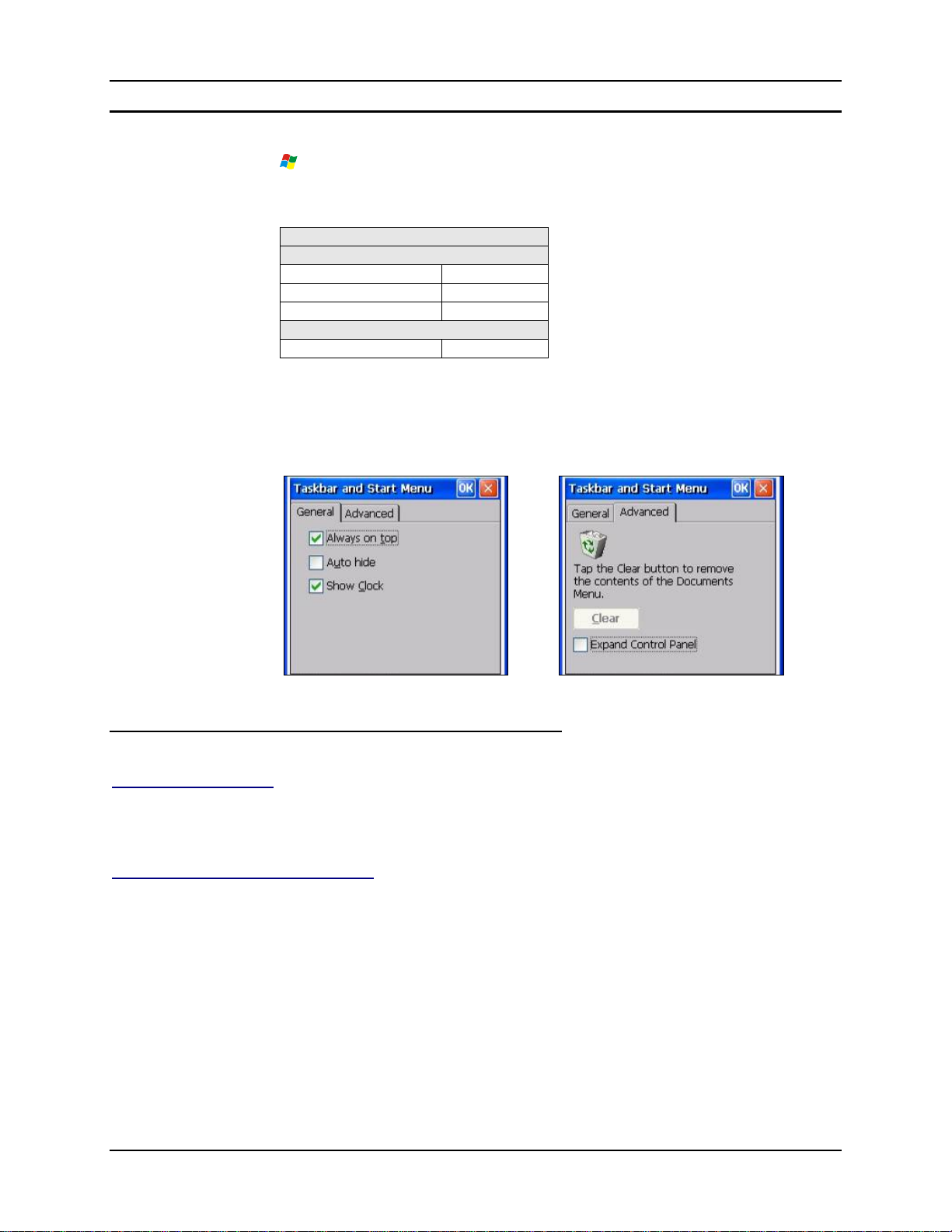
70 Start Menu Program Options
Taskbar
Access: | Settings | Taskbar and Start Menu
The Taskbar can be used to determine how the taskbar appears on the display. Use the Advanced
tab to clear the contents of the Documents menu.
Factory Default Settings
General
Always on Top Enabled
Auto hide Disabled
Show Clock Enabled
Advanced
Expand Control Panel Disabled
There are a few changes in the CE version of Taskbar as it relates to the general desktop PC
Windows Taskbar options.
When the taskbar is auto hidden, press the Ctrl key then the Esc key to make the Start button
appear.
Advanced Tab
Expand Control Panel
Tap the checkbox to have the Control Panel folders appear in drop down menu format from the
Settings | Control Panel menu option.
Clear Contents of Document Folder
Tap the Clear button to remove the contents of the Recently Opened Document folder.
Figure 3-3 Taskbar and Start Menu Properties
MX5X Reference Guide E-EQ-MX5CERG-F-ARC
Page 89

Control Panel Options 71
Control Panel Options
Access: | Settings | Control Panel or My Computer | Control Panel
Getting Help
Please tap the <?> box to get Help when changing Control Panel options .
Option Function
Accessibility Customize the way the keyboard, audio, display or mouse function for
users with hearing or viewing difficulties.
Administration LXE AppLock Administration utility. See Chapter 6 – AppLock for
details.
Audio Set volume parameters and assign sound wav files to CE events. Adjust
the volume, record gain, and sidetone for headphone, software and
microphone. Set volume for Bay Digital, CRMA Radio and Mixer.
Aironet Client Utility Set the parameters for a Cisco client. (See Chapter 5 Wireless Network
Configuration for instruction.) Requires Windows CE .NET 4.2
operating system.
Certificates Manage digital certificates used for secure communication.
Date/Time Set Date, Time, Time Zone, and Daylight Saving s.
Dialing Set dialup properties for internal modems (not supplied/supported by
LXE).
Display Set background graphic, window/menu appearance parameters and set
backlight properties and timers.
Handheld Displays hardware and software details. Tabs are Versions, Comms,
Radios, Misc. Enable or disable the touch panel (see Handheld
Properties | Misc).
Input Panel Select the current key / data input method.
Internet Options Set General, Connection, Security and Advanced options for Internet
connectivity. CE 5 version added Privacy and Popups options.
Keyboard Set key repeat delay and key repeat rate.
Mouse Set the double-click sensitivity for stylus taps on the touch screen.
Network and Dial Up
Options
Set network driver properties and network access properties.
Owner Set MX5X owner details (name, phone, etc) and Notes. Enter Network
ID for the device – user name, password, domain. Includes option to
display owner identification at power-on.
Password Set MX5X user access password properties.
E-EQ-MX5CERG-F-ARC MX5X Reference Guide
Page 90
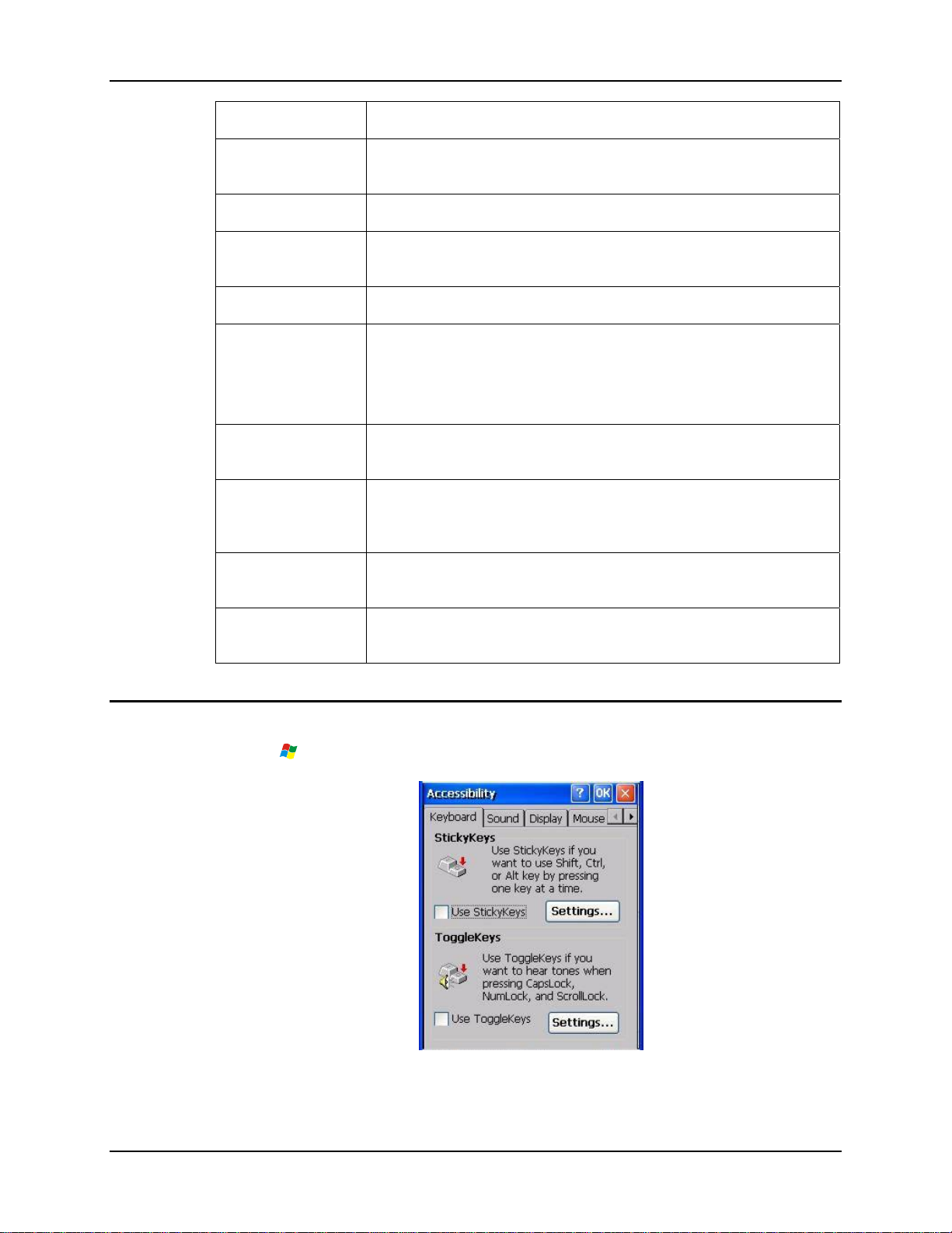
72 Control Panel Options
Option Function
PC Connection Control the connection between the MX5X and a local desktop or laptop
computer.
Power Set Power scheme properties. Review battery status and properties..
Regional Settings Set appearance of numbers, currency, time and date based on regional
and language settings.
Remove Programs Remove user installed programs in their entirety.
Scanner Set scanner keyboard wedge, scanner icon appearance, active scanner
port, and scan key settings. Assign baud rate, parity, stop bits and data
bits for available COM ports.
See section titled Determine Your Scanner Software Version.
Stylus Set double-tap sensitivity properties and/or calibrate the touch panel.
Enable or disable the touch panel (see Handheld Properties | Misc).
Symbol Set the parameters for a Symbol client. (See Chapter 5 Wireless Network
Configuration for instruction.) Requires Windows CE .NET 4.2
operating system.
Accessibility
System Review System and Computer data and revision levels. Adjust Storage
and Program memory settings. Enter device name and description.
Terminal Server
Client Licenses
Access: | Settings | Control Panel | Accessibility
Assign a stored Terminal Server Client license to the device.
Figure 3-4 Accessibility Options
MX5X Reference Guide E-EQ-MX5CERG-F-ARC
Page 91

Control Panel Options 73
Customize the way the keyboard, sound, display, mouse, automatic reset and notification sounds
function. There are a few changes from general desktop Accessibility options. Adjust the settings
and tap the OK box to save the changes. The changes take effect immediately.
The following exceptions are due to a limitation in the Microsoft Windows CE operating syste m:
If the ToggleKeys option is selected, please note that the ScrollLock key does not produce a sound
as the CapsLock and NumLock keys do.
If the SoundSentry option is selection, please note that ScrollLock does not produce a visual
warning as the CapsLock and NumLock keys do.
Administration – for AppLock
Access: | Settings | Control Panel | Administration
Use this option to set parameters for computers intended to be used as dedicated, single or
multiple application devices. In other words, only the application or feature(s) specified in the
AppLock configuration by the Administrator are available to the user.
LXE devices with the AppLock feature are shipped to start up in Administration mode with no
default password, and when the device is started for the first time, the user has full access to the
mobile device and no password prompt is displayed. After the Administrator specifies an
application or applications to lock, assigns a password and the device is rebooted (or the hotkey is
pressed), the mobile device is then in end-user mode.
AppLock also contains a component which sets configuration parameters and application launch
settings as specified by the Administrator.
See Chapter 6 - AppLock for further information and instruction.
E-EQ-MX5CERG-F-ARC MX5X Reference Guide
Page 92
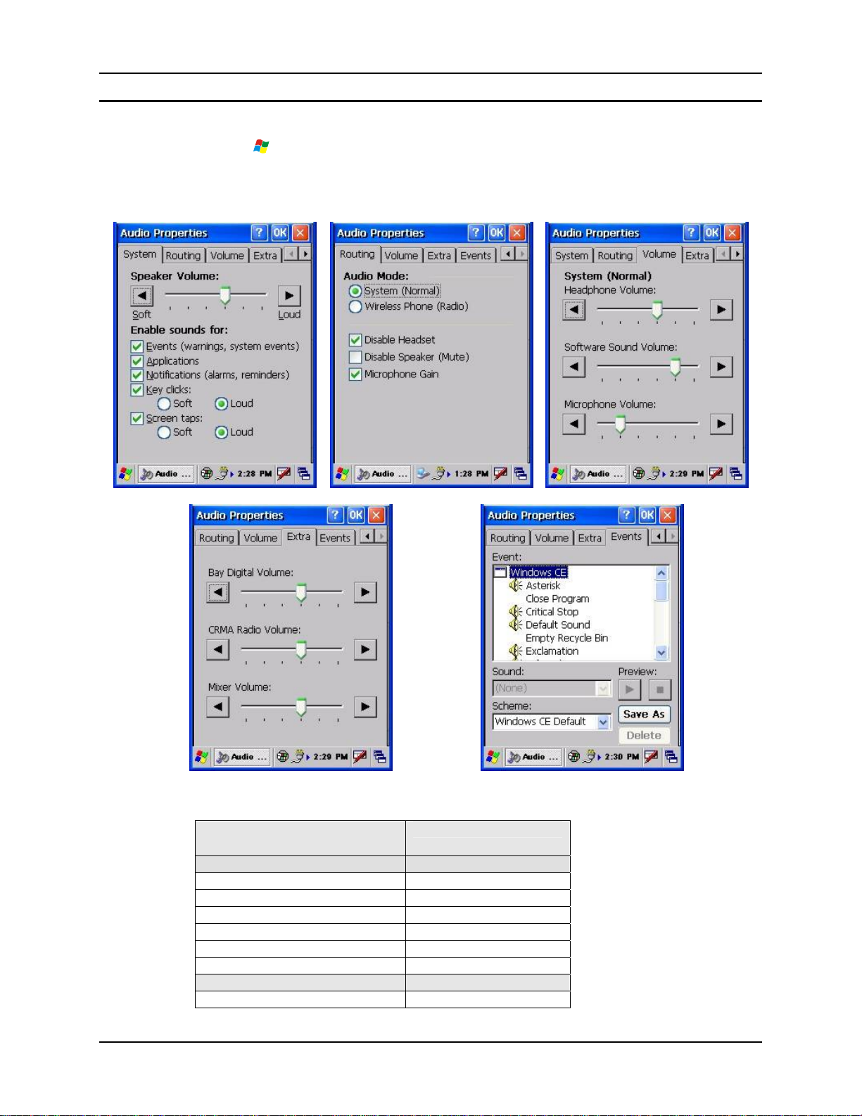
74 Control Panel Options
Audio
Access: | Settings | Control Panel | Audio
Set volume parameters and assign sound wav files for operating system events. Adjust the volume,
record gain, and sidetone for headphone, software and microphone. Set volume for Bay Digital,
CRMA Radio and Mixer.
Figure 3-5 Audio Properties
Factory Default Settings
System
Speaker Volume Loud
Events Enabled
Applications Enabled
Notifications Enabled
Key Clicks Loud
Screen taps Loud
Routing
System (Normal) Enabled
MX5X Reference Guide E-EQ-MX5CERG-F-ARC
Page 93
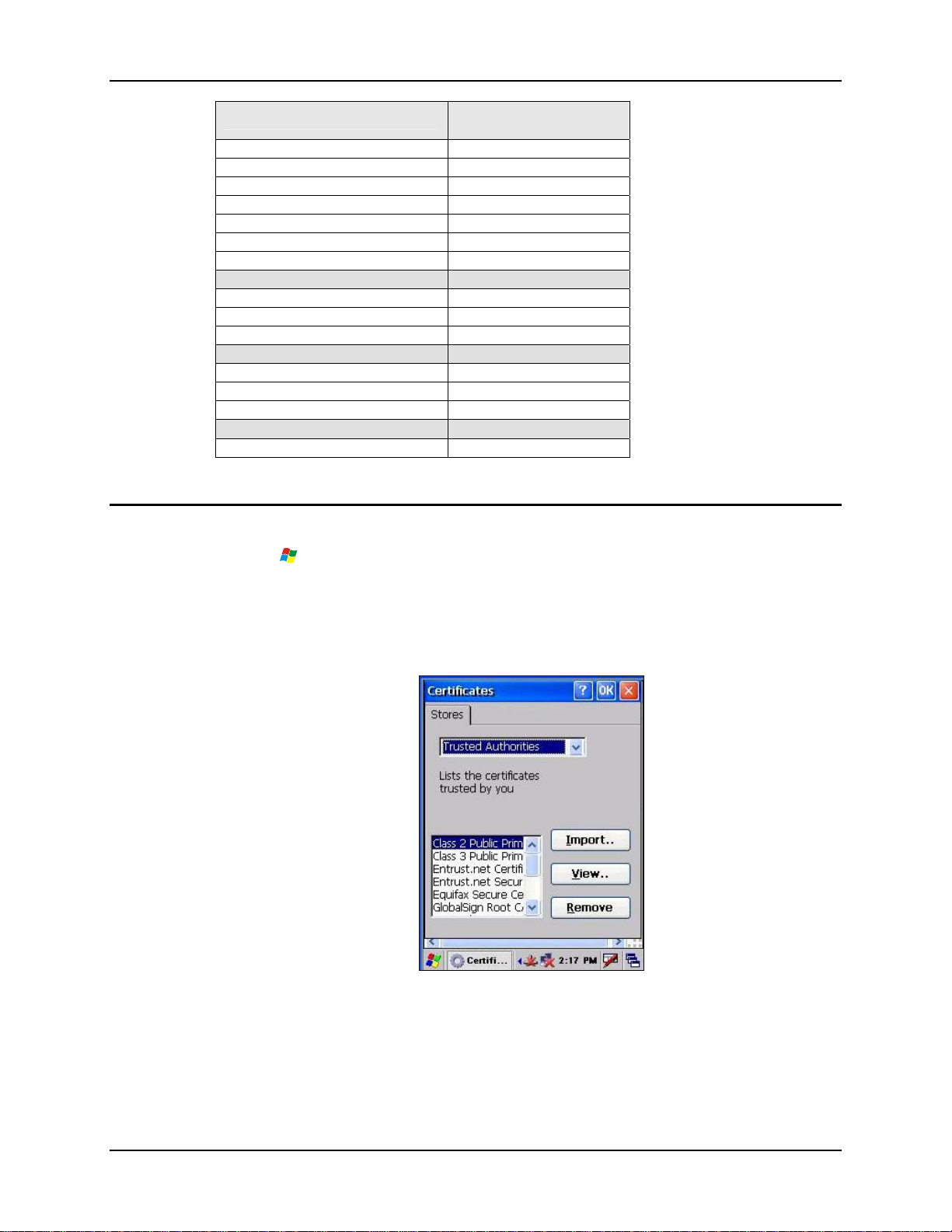
Control Panel Options 75
Certificates
Factory Default Settings
Wireless Phone (Network card) Disabled
Headset N/A
CRMA Radio N/A
Exp. Bay N/A
Disable Headset 1
Disable Speaker (Mute) Enabled
Microphone Gain Enabled
Volume
Headphone 60%
Software 80%
Microphone 60%
Extra Volume
Bay Digital 60%
CRMA Radio 60%
Mixer 60%
Events
Scheme Windows CE Default
Note: Bluetooth access, Bluetooth modules and Bluetooth Manager are not supported by LXE.
Access: | Settings | Control Panel | Certificates
Manage digital certificates used for secure communication.
Note: It is important that all dates are correct on the mobile devices when using any type of
certificate. Certificates are date sensitive and if the date is not correct authentication will
fail.
Figure 3-6 Digital Certificates
Lists the Stored certificates trusted by the MX5X user. These values may change based on the type
of wireless security resident in the client, access point or the host system.
E-EQ-MX5CERG-F-ARC MX5X Reference Guide
Page 94
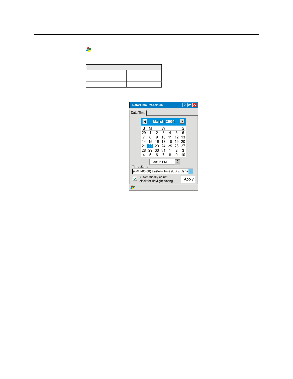
76 Control Panel Options
Date/Time
Access: | Settings | Control Panel | Date/Time Icon
Set Date, Time, Time Zone, and Daylight Savings after cold boot or at anytime.
Factory Default Settings
Current Time Midnight
Time Zone GMT-05:00
Daylight Savings Disabled
Note: Date and time is reset to the default value each time the MX5X is rebooted.
Figure 3-7 Date/Time Properties
There is minimal change from general desktop PC Date/Time Properties options. Adjust the
settings and tap the OK box or the Apply button to save the changes. The changes take effect
immediately. Double-tapping the time displayed in the Taskbar causes the Date/Time Properties
screen to appear.
MX5X Reference Guide E-EQ-MX5CERG-F-ARC
Page 95
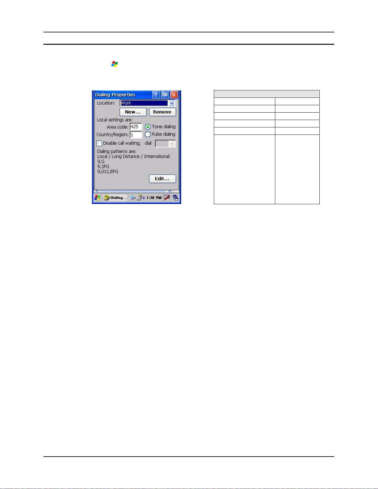
Control Panel Options 77
Dialing
Access: | Settings | Control Panel | Dialing
Set dialup properties for internal modems (not supplied/supported by LXE). Tap the <?> and
follow the instructions in Help.
Factory Default Settings
Location Work
Area Code 425
Tone Dialing Enabled
Country/Region 1
Disable Call Waiting Disabled
Figure 3-8 Dialing Properties
E-EQ-MX5CERG-F-ARC MX5X Reference Guide
Page 96
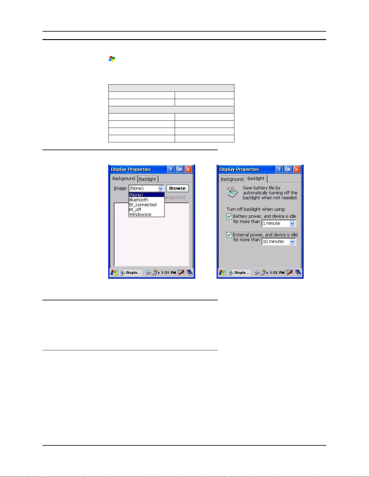
78 Control Panel Options
Display
Access: | Settings | Control Panel | Display Icon
Select the Desktop image and set the display/keypad backlight timers when on battery or extern al
power.
Factory Default Settings
Background Windows CE
Tile Disabled
Backlight
Battery Auto Turn Off Enabled
Idle Timer 1 minute
External Auto Turn Off Enabled
Idle Timer 10 minutes
Display Properties
Background
Backlight
Figure 3-9 Display Properties
There is no change from general desktop PC Display Properties / Background options. Select an
image from the dropdown list (or tap the Browse button to select an image from another folder) to
display on the Desktop, then tap the OK box to save the change. The change takes effect
immediately.
Adjust the settings and tap the OK box to save the changes. The changes take effect immediately.
When the backlight timer expires, the screen backlight is dimmed not turned off and the keypad
backlight is turned off. Default values are 1 minute for Battery power and 10 minutes for External
power.
MX5X Reference Guide E-EQ-MX5CERG-F-ARC
Page 97

Control Panel Options 79
Handheld
Access: | Settings | Control Panel | Handheld
Displays hardware, communicati ons, ver si o ns a n d WLA N cl i ent detai l s.
How to Disable Touch and / or Calibration upon Cold Reset
Access: | Settings | Control Panel | Handheld | Misc tab
Use this option to disable the touch panel. It can also be used to disable the touch screen
calibration configuration during a Cold Reset. When touch is disabled, the keypad must be used
for input. The Input Panel cannot be used.
Disable Touch Panel and Calibration
Access: My Computer | System
Create a file on the CF card (My Computer\System folder) named DisableTouchScreen.dat. If this
file is present on the CF card, the touch screen will be disabled, and calibration will NOT be
requested upon a cold reset.
Disable Touch Panel Only
Access:
To just disable the touch panel (calibration still required upon co ld reset), enable (tap) the Touch
Panel Disabled checkbox on the Misc tab in the Handheld Properties Control Panel.
When checked, the touch panel is disabled. When touch is disabled, the keypad must be used for
input. The Input Panel cannot be used.
How to Re-enable Touch and / or Calibration upon Cold Reset
Access: My Computer | System
To enable Touch Panel and Calibration, delete the file named DisableTouchScreen.dat on the CF
card (My Computer\System folder). When this file is present on the CF card, the touch screen is
disabled, and calibration does not occur after a cold reset.
To enable the Touch Panel only, uncheck the Touch Panel Disabled checkbox on the Misc tab in
the Handheld Properties Control Panel (Start/Settings/Control Panel/Handheld/Misc tab).
| Settings | Control Panel | Handheld | Misc tab
E-EQ-MX5CERG-F-ARC MX5X Reference Guide
Page 98
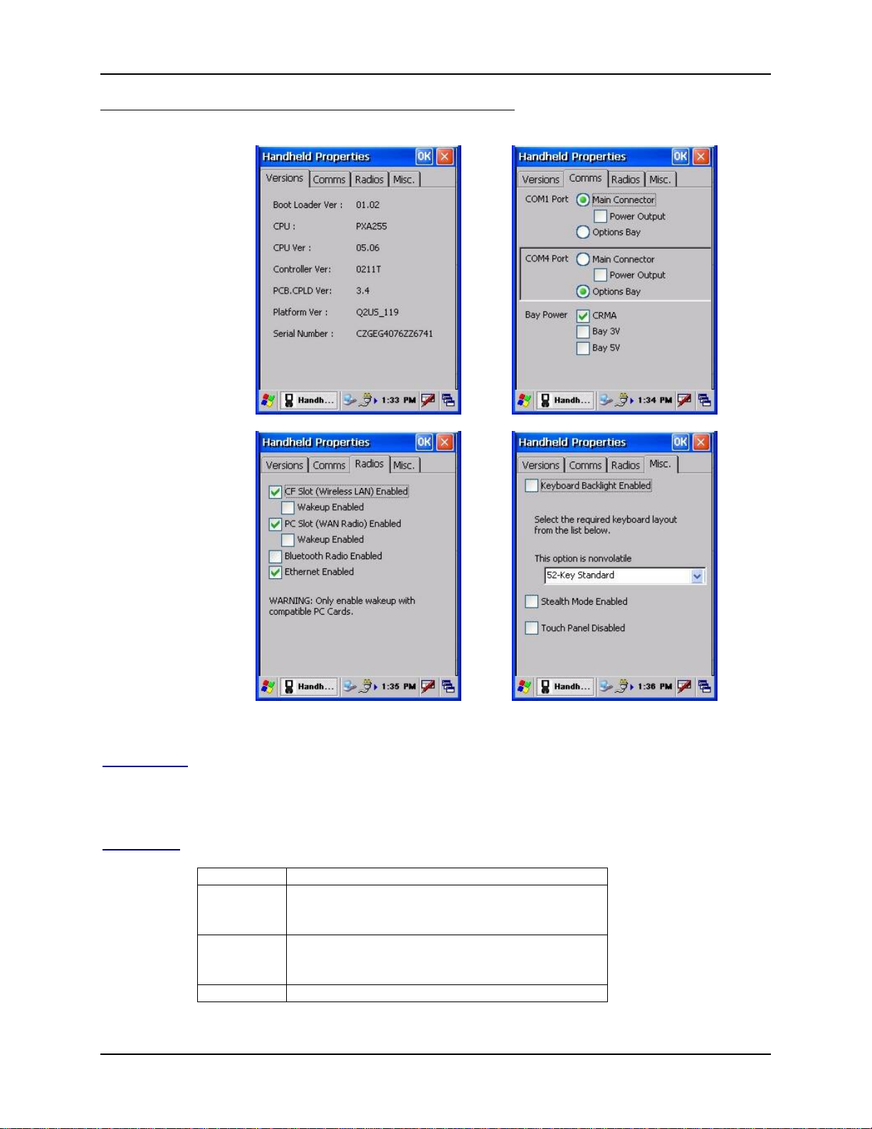
80 Control Panel Options
Handheld Properties
Figure 3-10 Handheld Properties – Version 1.02
Versions tab
Comms tab
Bootloader, CPU type, CPU, Controller, PCB.CPLD, Platform versions. Mobile device serial
number.
Comms Default
COM 1 Port Main Connector enabled
Disabled: Power Output for Main Connector,
Options Bay
COM 4 Port Main Connector enabled
Disabled: Power Output for Main Connector,
Options Bay
Bay Power Disabled: CRMA, Bay 3V, Bay 5V
MX5X Reference Guide E-EQ-MX5CERG-F-ARC
Page 99
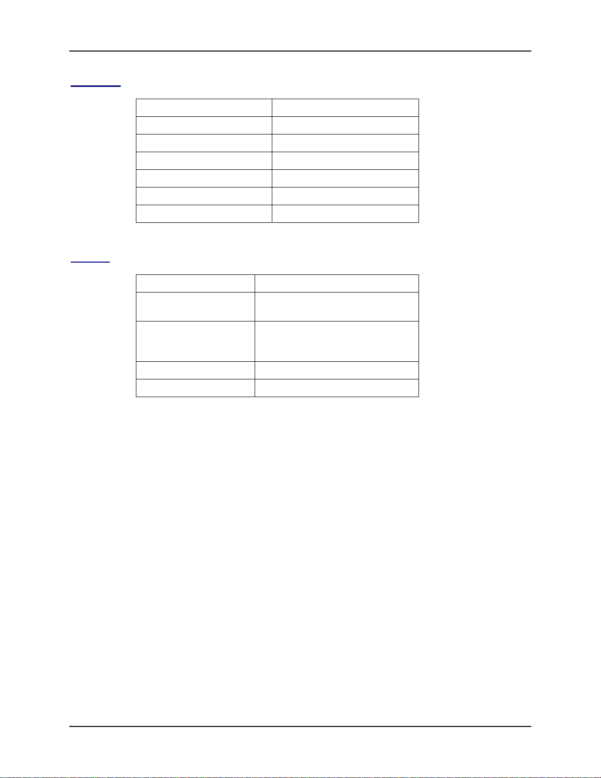
Control Panel Options 81
Radios tab
Parameter Default
CF Slot Enabled Enabled (checkmark)
CF Slot Wakeup Enabled Disabled (blank)
PC Slot Enabled Enabled (checkmark)
PC Slot Wakeup Enabled Disabled (blank)
Bluetooth Radio Enabled Disabled (blank) [see Note]
Ethernet Enabled Enabled (checkmark)
Note: Bluetooth access, modules and Bluetooth Manager are not supported by LXE.
Misc tab
Parameter Defaults
Keyboard Backlight
Enabled
Nonvolatile option 52-key Standard
Stealth Mode Enabled Disabled (blank) [see Note]
Touch Panel Disabled Disabled (blank) [see Note]
Note: See previous section titled How To Disable Touch and / or Calibration upon Cold Reset
and How To Enable Touch and / or Calibration upon Cold Reset.
Enabled (checkmark)
Options: 52-key Phone, 52-ke y
MultiKey
E-EQ-MX5CERG-F-ARC MX5X Reference Guide
Page 100
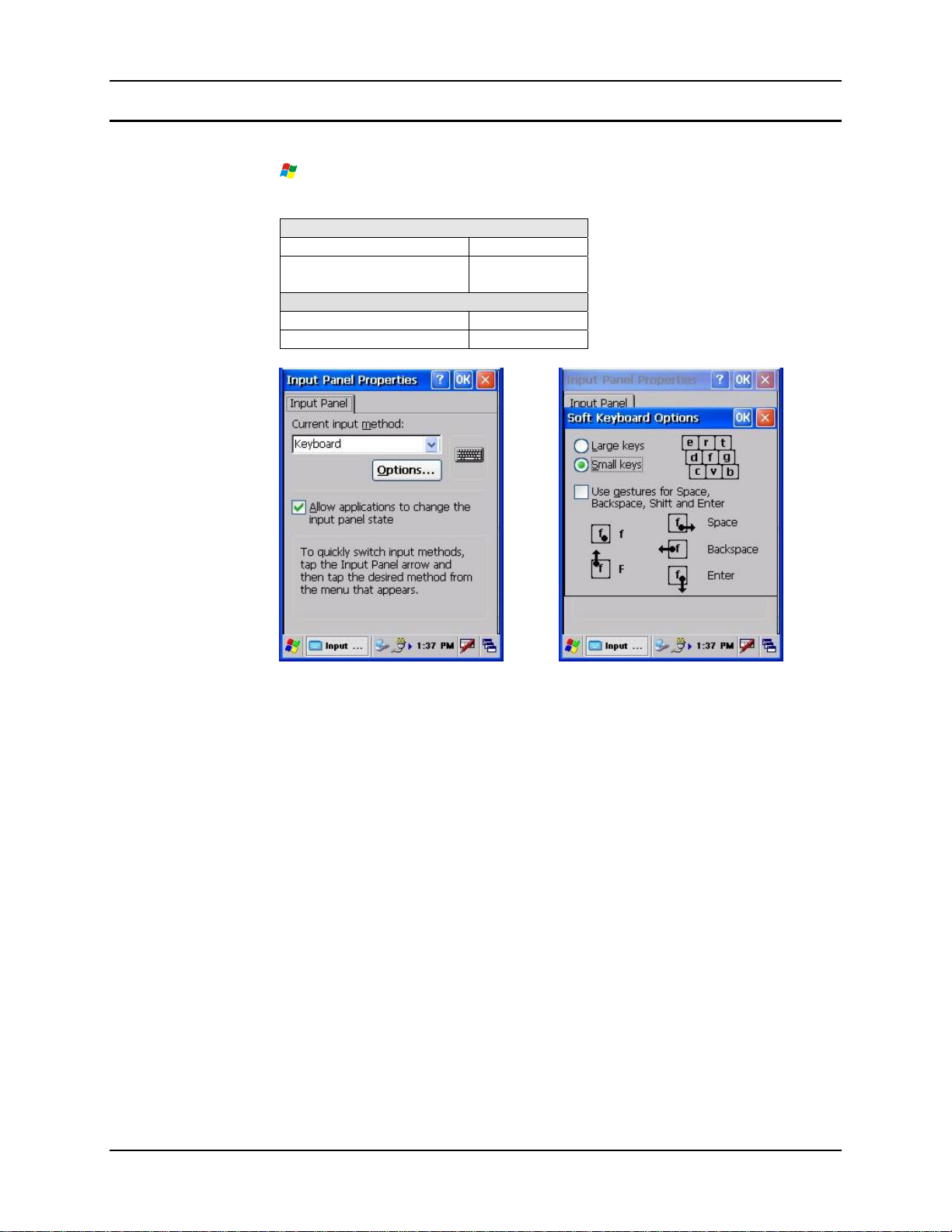
82 Control Panel Options
Input Panel
Access: | Settings | Control Panel | Input Panel
Select the current key / data input method.
Factory Default Settings
Input Method Keyboard
Allow applications to
change input panel state
Options
Keys Small keys
Use gestures Disabled
Enabled
Figure 3-11 Input Panel
Use this option to make the Input Panel or the physical keypad primarily available when entering
data. When new key maps are added to the registry, they will appear in the Input Method
dropdown list.
Tap the Input Panel icon in the taskbar to toggle the on-screen Keyboard on and off.
MX5X Reference Guide E-EQ-MX5CERG-F-ARC
 Loading...