

Page 1
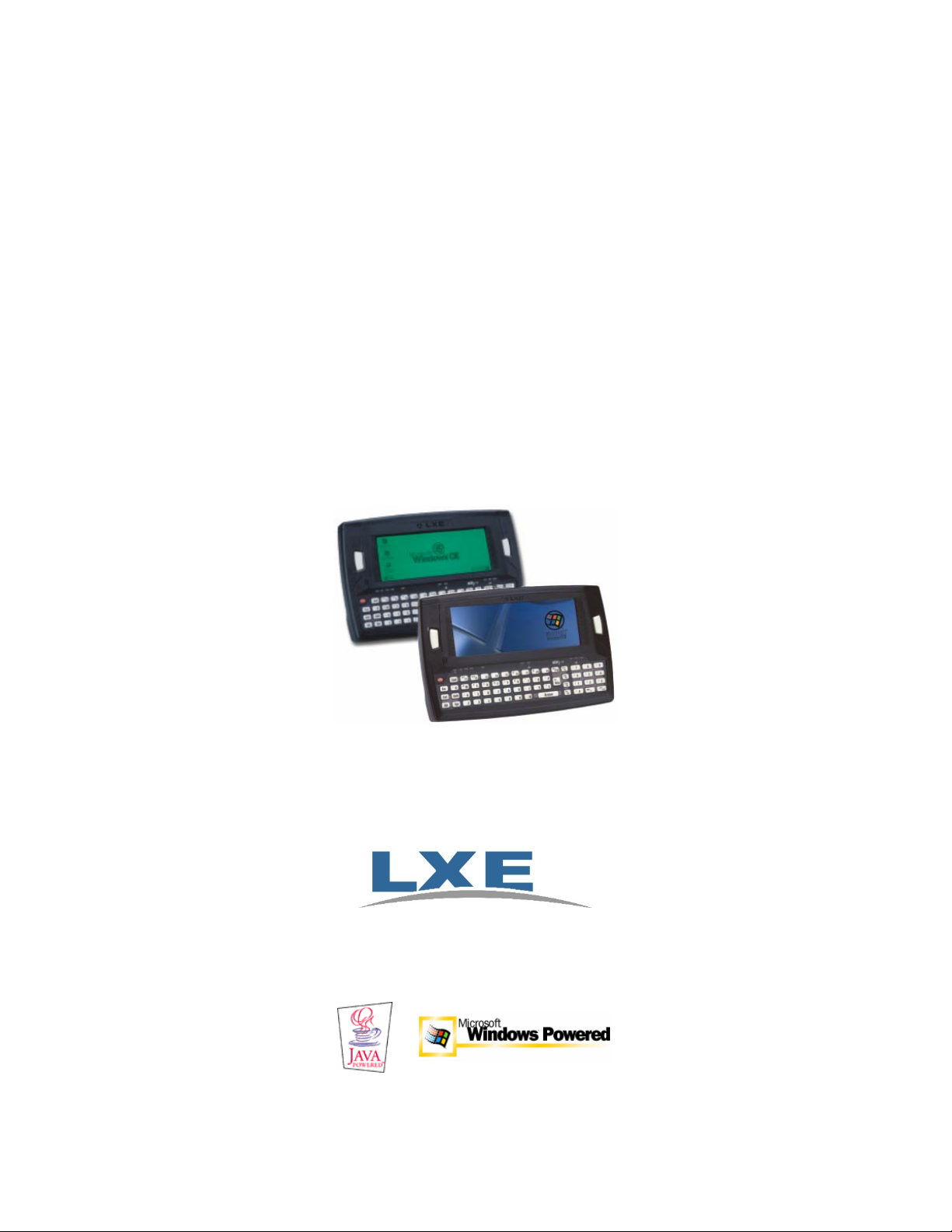
MX3-CE User’s Guide
(MX3 mobile device running Microsoft® Windows® CE 3.0 Operating System)
IMPORTANT NOTICE
LXE’s MX3-CE is obsolete. This electronic manual has been made available as a
courtesy to LXE's MX3-CE customers. Please contact your LXE customer support
representative for assistance.
Copyright © June 2005 by LXE Inc.
All Rights Reserved
MX3CEA136OPGD
E-EQ-MX3CEOGWW-F-ARC
Page 2
Language: English
Notices
LXE Inc. reserves the right to make improvements or changes in the products described in this manual at any time
without notice. While reasonable efforts have been made in the preparation of this document to assure its accuracy,
LXE assumes no liability resulting from any errors or omissions in this document, or from the use of the
information contained herein. Further, LXE Incorporated, reserves the right to revise this publication and to make
changes to it from time to time without any obligation to notify any person or organization of such revision or
changes.
Copyright Notice:
This manual is copyrighted. All rights are reserved. This document may not, in whole or in part, be copied,
photocopied, reproduced, translated or reduced to any electronic medium or machine-readable form without prior
consent, in writing, from LXE Inc.
Copyright © 2005 by LXE Inc. An EMS Technologies Company.
125 Technology Parkway, Norcross, GA 30092 U.S.A. (770) 447-4224
Trademarks:
LXE® is a registered trademark of LXE Inc. Microsoft, Windows and the Windows logo are registered trademarks
of Microsoft Corporation in the United States and/or other countries. Java and Java-based trademarks and logos are
trademarks or registered trademarks of Sun Microsystems, Inc. in the U.S. or other countries, and are used under
license. All other brand or product names are trademarks or registered trademarks of their respective companies or
organizations. When this manual is in PDF format: "Acrobat ® Reader Copyright © 1987-2005 Adobe Systems
Incorporated. All rights reserved. Adobe, the Adobe logo, Acrobat, and the Acrobat logo are trademarks of Adobe
Systems Incorporated." applies.
The user is strongly encouraged to read Appendix B, "Regulatory Notices and Safety
Information". Important safety cautions, warnings and regulatory information is
contained in Appendix B.
Revision Notice
MX3-CE User's Guide
Upgrade From Revision E to Revision F
Rev Location Description
E Entire Manual Updated structure to reflect modular style/content effective January 2004. Changed
guide name to “MX3-CE User’s Guide”.
E Introduction Streamlined “Overview”. Added new accessory number for 24V-72V PS. Added
8500 series tethered scanners to “Accessories”. Added recommendation to connect
the MX3-CE to external power periodically to maintain optimum charge in the
batteries.
E Appendix B,
Regulatory
Notices
F Entire Manual Archived. Available on LXE ServicePass website only. Product’s replacement
Revised Approvals table. Added 6816 Declaration of Conformity. (Rev D)
Updated 6726 Declaration of Conformity. (Rev E)
device is the LXE MX3X.
Removed “Power Modes” section. Pointed reader to MX3-CE Reference Guide for
power mode details/explanations. Updated Accessories List.
Page 3

Table of Contents
NTRODUCTION 1
I
Overview.................................................................................................................... 1
About Lithium-Ion Batteries................................................................................................................. 1
Document Conventions......................................................................................................................... 2
MX3-CE Environmental Specifications................................................................................................ 2
Laser Warnings and Labels ..................................................................................... 3
Quick Start.................................................................................................................4
Components .......................................................................................................................................... 5
Insert Main Battery ............................................................................................................................... 7
Power Button......................................................................................................................................... 8
Reboot Sequence ................................................................................................................................ 8
Attach the Stylus Clip (Optional).......................................................................................................... 8
Connect External Power Supply (Optional).......................................................................................... 9
Connect Audio Jack (Optional)............................................................................................................. 9
Attach Hand Strap (Optional) .............................................................................................................10
Tapping the Touchscreen with a Stylus .............................................................................................. 11
Keypad Shortcuts.............................................................................................................................. 11
Set The Display Contrast .................................................................................................................... 12
Set the Display Backlight Timer ......................................................................................................... 12
Set the Display Blanking Timer.......................................................................................................... 13
Set the MX3-CE Power Off Timer ..................................................................................................... 14
Saving Settings.................................................................................................................................... 14
Set The Audio Speaker Volume.......................................................................................................... 15
Using the Keypad ............................................................................................................................. 15
Using the Touch Screen.................................................................................................................... 15
Enter Data ........................................................................................................................................... 16
Keypad Entry.................................................................................................................................... 16
Stylus Data Entry.............................................................................................................................. 16
Scanner Entry ...................................................................................................................................17
Charge Battery in MX3 Multi-Charger ...................................................................
18
Getting Help.............................................................................................................
Manuals............................................................................................................................................... 19
Accessories.......................................................................................................................................... 19
HE MX3-CE HAND HELD COMPUTER 21
T
19
Touch Screen Display.............................................................................................21
Display Backlight................................................................................................................................ 21
Touch Screen Calibration.................................................................................................................... 22
Cleaning the Glass Display/Scanner Aperture .................................................................................... 22
Programmable Buttons ..........................................................................................
E-EQ-MX3CEOGWW-F-ARC MX3-CE User’s Guide
23
Page 4

ii Table of Contents
Endcaps and COM Ports........................................................................................ 24
Tethered Scanners ............................................................................................................................... 25
USB Port ............................................................................................................................................. 25
IR Port......................................................................................................................
25
The Keypad..............................................................................................................
Scan Key Function .............................................................................................................................. 26
Enter Key Function ............................................................................................................................. 26
2nd Key Function................................................................................................................................ 26
Ctrl Key Function................................................................................................................................ 26
Alt Key Function................................................................................................................................. 27
Shft Key Function ............................................................................................................................... 27
Spc Key Function................................................................................................................................ 27
Mode Key Functions........................................................................................................................... 27
Caps Key and CapsLock Mode ........................................................................................................ 27
Keypress Sequences ............................................................................................................................ 27
Keypad LED Functions....................................................................................................................... 28
26
Batteries...................................................................................................................29
Main Battery ....................................................................................................................................... 29
Backup Battery.................................................................................................................................... 30
Battery Hot-Swapping......................................................................................................................... 30
Battery Chargers.....................................................................................................31
LXE Multi-Charger............................................................................................................................. 31
External Power Supply (Optional) ...................................................................................................... 31
Cradles..................................................................................................................... 32
Desktop Cradle.................................................................................................................................... 32
Status LED........................................................................................................................................ 33
Power Connector .............................................................................................................................. 33
RS-232 Connector ............................................................................................................................ 34
Vehicle Mount Cradle......................................................................................................................... 35
Status LED........................................................................................................................................ 35
Power Connector .............................................................................................................................. 36
RS-232 Connector ............................................................................................................................ 36
APPENDIX A KEY MAPS 39
Keypad..................................................................................................................... 39
Key Map 101-Key Equivalencies ....................................................................................................... 39
A
PPENDIX B REGULATORY NOTICES AND SAFETY INFORMATION 45
INDEX 57
MX3-CE User’s Guide E-EQ-MX3CEOGWW-F-ARC
Page 5

Table of Contents iii
Illustrations
Figure 1 CDRH / IEC 825 Caution Label Location - MX3-CE, Back ................................................................3
Figure 2 Caution Label - Scanner ........................................................................................................................ 3
Figure 3 Hardware Configuration........................................................................................................................4
Figure 4 Front of MX3-CE ..................................................................................................................................5
Figure 5 Endcap ...................................................................................................................................................6
Figure 6 Back of MX3-CE...................................................................................................................................6
Figure 7 MX3-CE Battery Contacts.....................................................................................................................7
Figure 8 Main Battery..........................................................................................................................................7
Figure 9 Power Button.........................................................................................................................................8
Figure 10 Connect External Power Supply.......................................................................................................... 9
Figure 11 Connect Audio Jack.............................................................................................................................9
Figure 12 MX3-CE With Handstrap Installed ................................................................................................... 10
Figure 13 Display Properties / Backlight...........................................................................................................12
Figure 14 Display Properties / Blanking Timer .................................................................................................13
Figure 15 Power Off Timer................................................................................................................................14
Figure 16 Adjust Audio Volume........................................................................................................................15
Figure 17 Scan Beam.........................................................................................................................................17
Figure 18 Scanner LED Location ......................................................................................................................17
Figure 19 Insert Main Battery in Charging Cup ................................................................................................18
Figure 20 MX3-CE Touch Screen Display........................................................................................................ 21
Figure 21 Touch Screen Recalibration...............................................................................................................22
Figure 22 Programmable Buttons (Scan / Enter) ...............................................................................................23
Figure 23 Endcap Connectors............................................................................................................................24
Figure 24 IR Port (COM 2)................................................................................................................................25
Figure 25 The QWERTY Keypad .....................................................................................................................26
Figure 26 Function LEDs...................................................................................................................................28
Figure 27 Main Battery......................................................................................................................................29
Figure 28 MX3 Multi-Charger and MX3 Multi-Charger Plus...........................................................................31
Figure 29 US AC/DC 12V Power Supply and Cigarette Lighter Adapter.........................................................31
Figure 30 International AC/DC 12V Power Supply .......................................................................................... 31
Figure 31 MX3-CE in the Cradles .....................................................................................................................32
Figure 32 Desktop Cradle Status Indicator ........................................................................................................33
Figure 33 Desktop Cradle Power Connector .....................................................................................................33
Figure 34 Desktop Cradle RS-232 Connector ...................................................................................................34
Figure 35 Vehicle Mount Cradle - Front ...........................................................................................................35
Figure 36 Vehicle Cradle Power Connector ......................................................................................................36
Figure 37 Vehicle Cradle RS-232 Connector ....................................................................................................36
Figure 38 QWERTY Keypad.............................................................................................................................39
E-EQ-MX3CEOGWW-F-ARC MX3-CE User’s Guide
Page 6

iv Table of Contents
MX3-CE User’s Guide E-EQ-MX3CEOGWW-F-ARC
Page 7

Overview
Introduction
The MX3-CE is a rugged, portable, hand-held Windows CE computer capable of wireless data
communications. The MX3-CE can transmit information using a 2.4 GHz radio (with an internally
mounted antenna) and it can store information for later transmission through an RS-232 or
InfraRed port.
The MX3-CE is horizontally oriented and features backlighting for the display. The touch-screen
display supports graphic features and Windows icons that the Windows CE operating system
supports. The keys on the keypad are constructed of a phosphorescent material that can easily be
seen in dimly lighted areas. The MX3-CE is a Windows CE compatible computer that can be
scaled from a limited function batch computer to an integrated RF scanning computer. A stylus is
enclosed with the MX3-CE to assist in entering data and configuring the unit.
Related Manuals
The “MX3-CE Reference Guide” contains MX3-CE technical specifications, instruction and
further information. Please refer to the "MX3 Cradle Reference Guide" for technical information
relating to the MX3 Desk Top and Vehicle Mount cradles. If you need to set up the integrated
scanner barcode reading parameters, please refer to the “Integrated Scanner Programming Guide”
on the LXE Manuals CD or the LXE website www.lxe.com.
Note: Until the Main Battery and Backup Battery are completely depleted, the MX3-CE is
always drawing power from the batteries (On).
About Lithium-Ion Batteries
Li-Ion batteries (like all batteries) gradually lose their capacity over time (in a linear fashion) and
never just stop working. This is important to remember -- the MX3-CE is always 'on' even when
in the Suspend state and draws battery power at all times. Use the Start | Settings | Control Panel |
Power Properties | Charge tab to check the battery status and power reading. The following chart
is an approximation. Actual battery capacity may vary based on usage, ambient temperature and
peripherals drawing power from the MX3-CE:
100% capacity 1400 mAh minimum
80% capacity 1120 mAh minimum
Deciding when to put a fully charged Main Battery pack in the MX3-CE is difficult to quantify
because it is very application specific. 1000 mAh may be the cutoff for one customer who uses the
computer frequently, while 300 mAh may be perfectly fine for a customer who occasionally uses
the computer. You need to determine the point at which battery life becomes unacceptable for
your business practices and replace the Main Battery pack before that point.
Note: Always store unused mobile devices with a fully charged main battery pack installed.
LXE recommends the mobile device be connected to an external power source
periodically to retain optimum power levels in the main battery pack and the backup
battery.
E-EQ-MX3CEOGWW-F-ARC MX3-CE User’s Guide
Page 8
2 Overview
Document Conventions
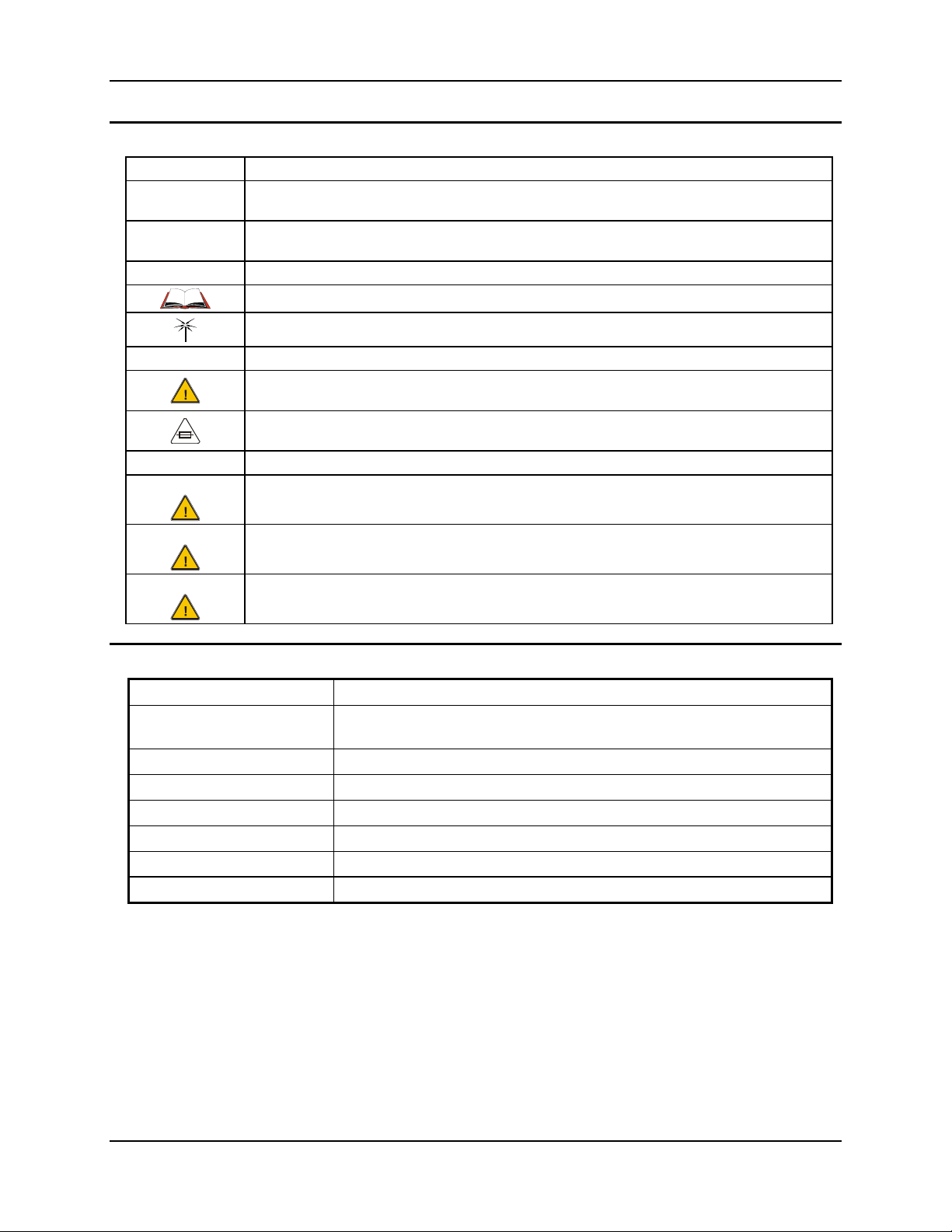
ALL CAPS All caps are used to represent disk directories, file names, and application names.
Menu | Choice
"Quotes"
< > Indicates a key on the keypad (for example, <Enter> ).
ATTENTION
Note: Keyword that indicates immediately relevant information.
CAUTION
WARNING
DANGER
Rather than use the phrase "choose the Save command from the File menu", this manual uses the
convention "choose File | Save".
Indicates the title of a book, chapter or a section within a chapter (for example, "Document
Conventions").
Indicates a reference to other documentation.
Differences in operation or commands due to radio type.
Keyword that indicates vital or pivotal information to follow.
Attention symbol that indicates vital or pivotal information to follow. Also, when marked on product,
means to refer to the product user’s guide.
International fuse replacement symbol. When marked on the product, the label includes fuse ratings
in volts (v) and amperes (a) for the product.
Keyword that indicates a potentially hazardous situation which, if not avoided, may result in minor
or moderate injury.
Keyword that indicates a potentially hazardous situation which, if not avoided, could result in death
or serious injury.
Keyword that indicates a imminent hazardous situation which, if not avoided, will result in death or
serious injury.
MX3-CE Environmental Specifications
Feature Specification
Operating Temperature
Storage Temperature -22°F to 158°F (-30°C to 70°C) [non-condensing]
Water and Dust IEC IP65
Operating Humidity Up to 90% non-condensing at 104°F (40°C)
Vibration Based on MIL Std 810D
ESD 8 kV air, 4kV contact
Shock 75G, 5ms duration, 100 shock impacts
Monochrome display : -4°F to 122°F (20°C to 50°C) [non-condensing]
Color display : 32°F to 122°F (0°C to 50°C) [non-condensing]
MX3-CE User’s Guide E-EQ-MX3CEOGWW-F-ARC
Page 9
Laser Warnings and Labels 3
Laser Warnings and Labels
• Do not look into the laser’s lens.
• Do not stare directly into the laser beam.
• Do not remove the laser caution labels from the MX3-CE.
• Do not connect the laser barcode window to any other device. The laser barcode window is
certified for use with the MX3-CE only.
Caution:
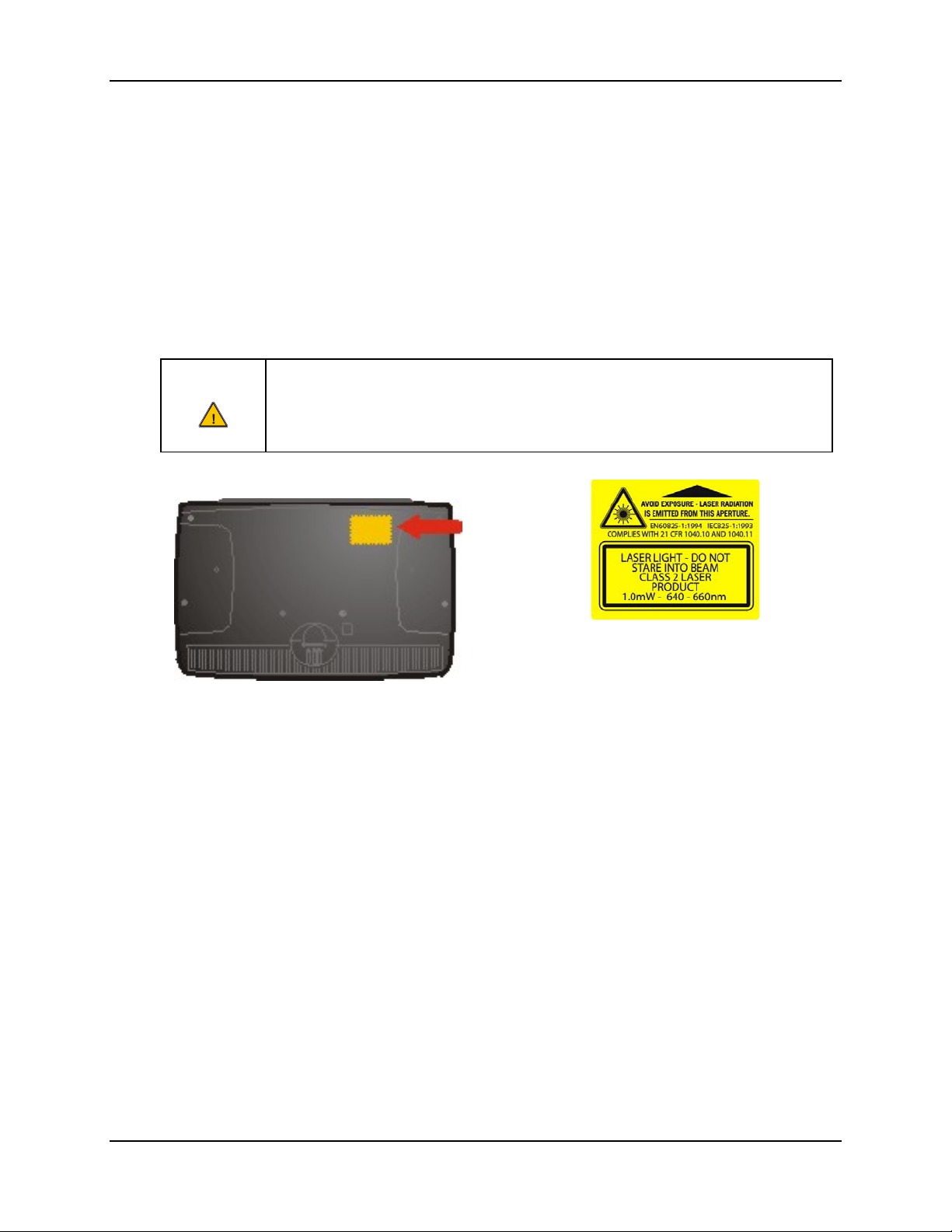
Figure 1 CDRH / IEC 825 Caution Label Location -
Laser radiation when open. Please read the caution labels.
Use of controls, adjustments or performance of procedures other than those specified
herein may result in hazardous radiation exposure.
MX3-CE, Back
Figure 2 Caution Label - Scanner
E-EQ-MX3CEOGWW-F-ARC MX3-CE User’s Guide
Page 10
4 Quick Start
Quick Start
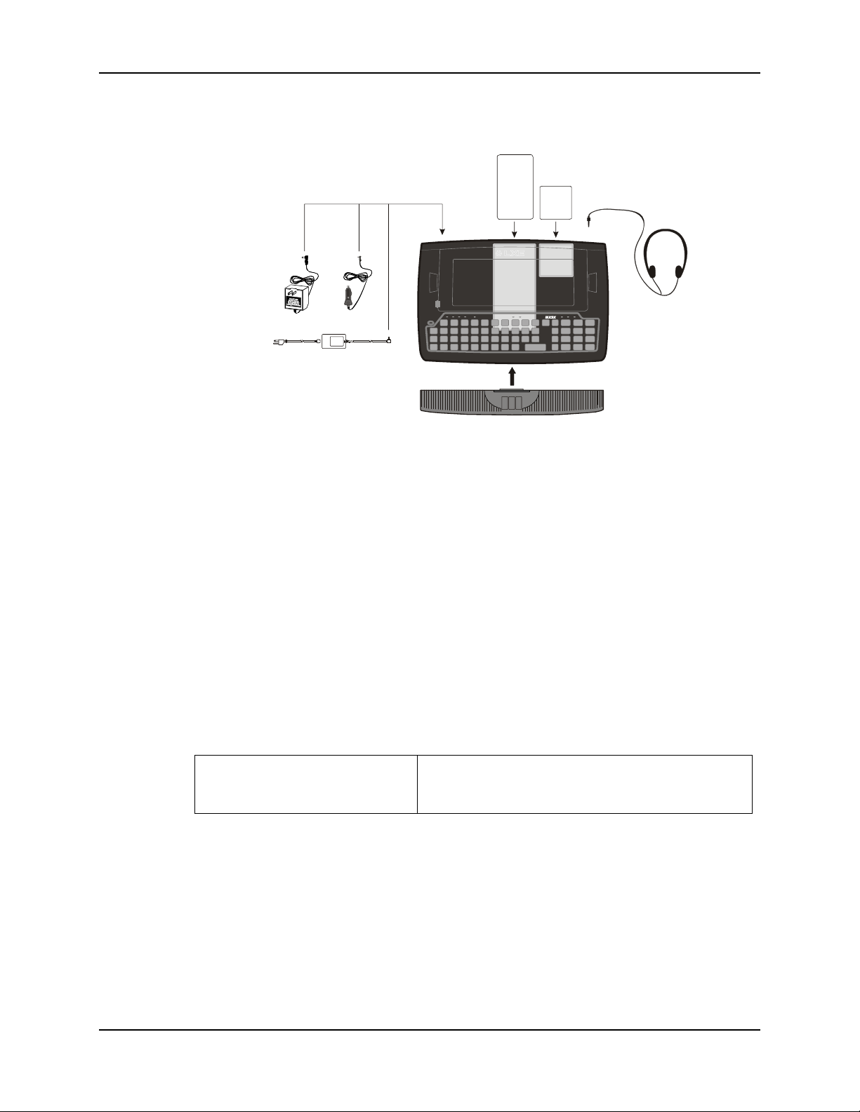
Figure 3 Hardware Configuration
This section's instructions are based on the assumption that your new system is pre-configured and
requires only accessory installation (e.g. hand strap, external barcode scanner) and a power
source.
Use this guide as you would any other source book -- reading portions to learn about the MX3CE, and then referring to it when you need more information about a particular subject. This guide
takes you through an introduction to and operation of the LXE MX3-CE.
In general, the sequence of events is:
1. Insert a fully charged battery. (Always put a fully charged battery in the MX3-CE at
the beginning of the shift or workday.)
2. Connect an external power source to the unit (if required).
3. If the screen does not automatically display, tap the Power button.
4. Adjust screen display, audio volume and other parameters if desired.
Troubleshooting
Can’t align the screen, change the
date/time or adjust the volume.
AppLock is installed and running on the mobile device.
AppLock restricts access to the control panels. Contact
your System Administrator.
MX3-CE User’s Guide E-EQ-MX3CEOGWW-F-ARC
Page 11
Quick Start 5
Components
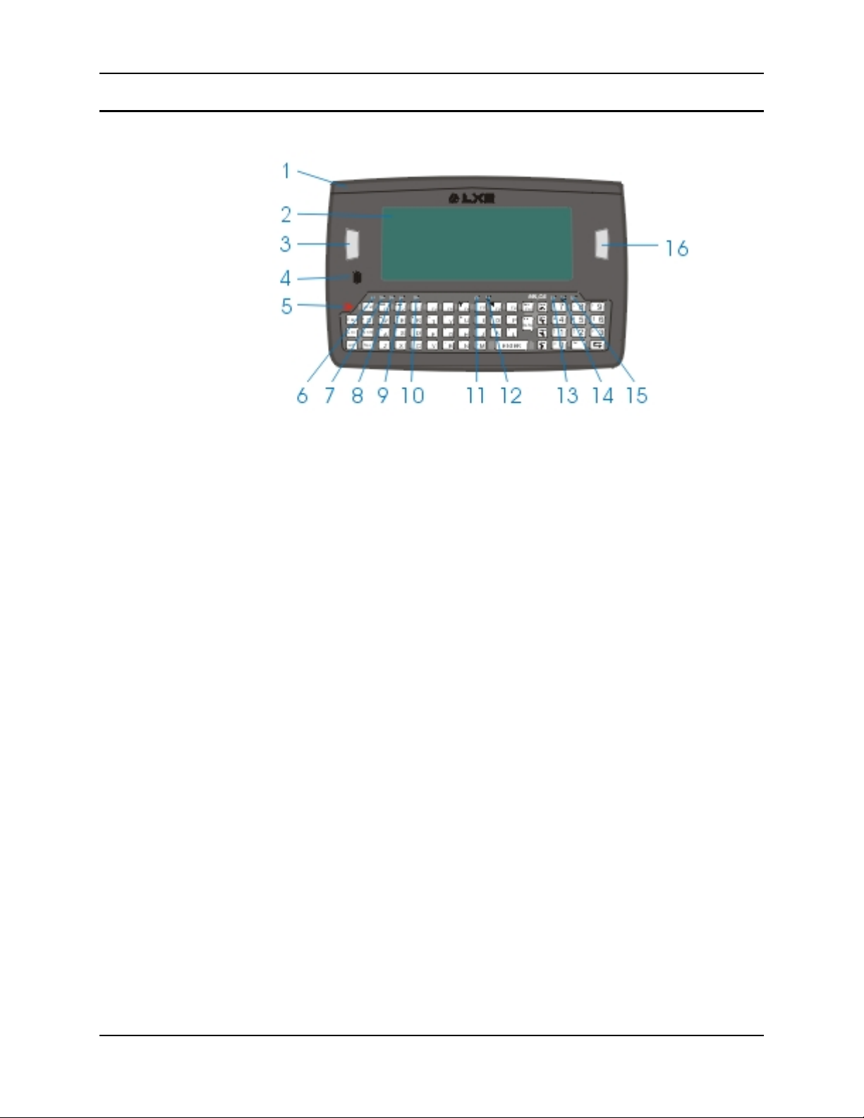
Figure 4 Front of MX3-CE
1 Endcap 9 Shift LED
2 Touch Screen Display 10 Caps LED
3 Scan or Enter (programmable) 11 Scanner LED
4 Beeper 12 Backup Battery LED
5 On/Off Button 13 Status LED
6 2nd LED 14 Main Battery LED
7 Alt LED 15 Charger LED
8 Ctrl LED 16 Scan or Enter (programmable)
E-EQ-MX3CEOGWW-F-ARC MX3-CE User’s Guide
Page 12
6 Quick Start
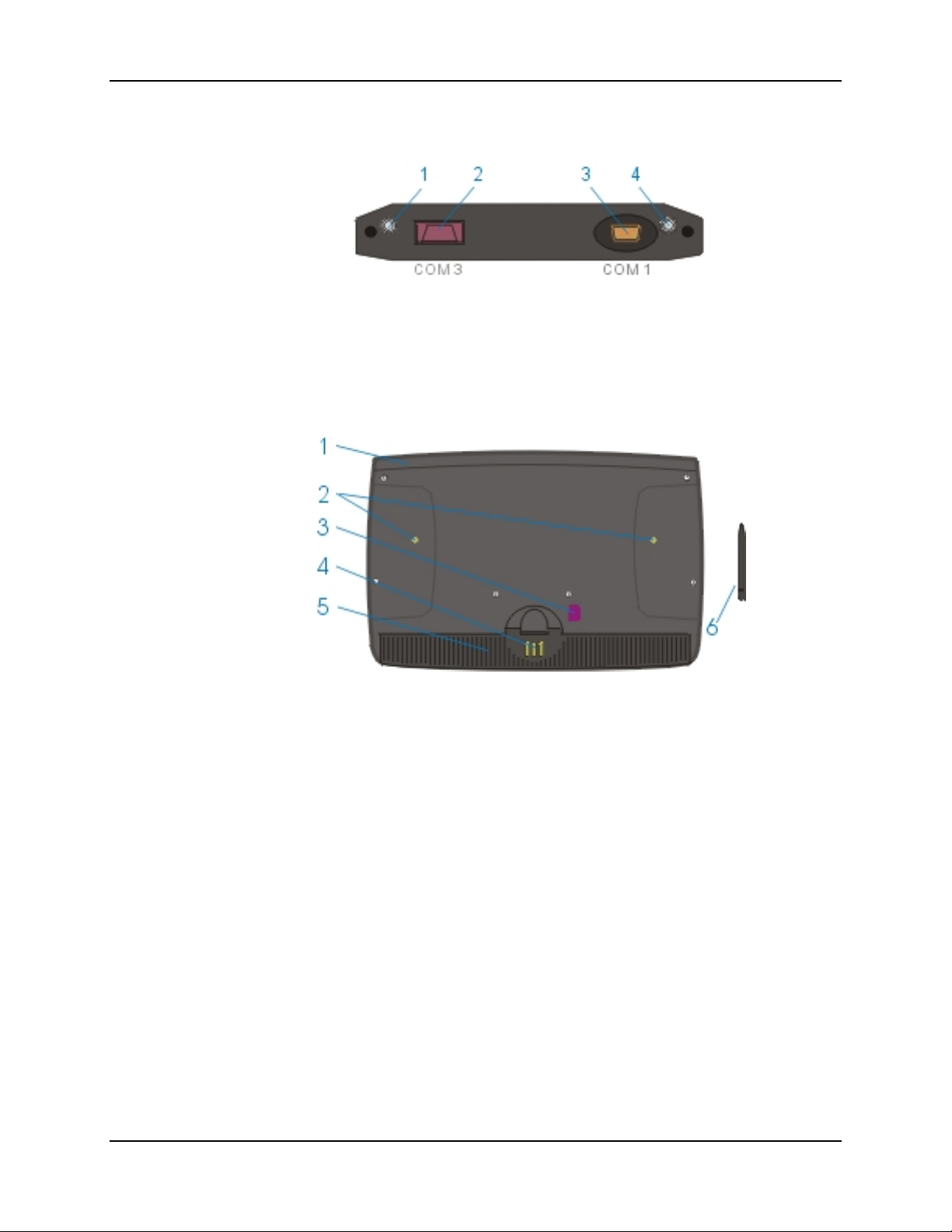
Figure 5 Endcap
1 DC Power Jack 3 Com 1 (Serial or USB) Port
2 Com 3 (Serial or Scanner) Port 4 Audio Jack
Figure 6 Back of MX3-CE
1 Endcap 4 Cradle Input Contacts
2 Leather Handstrap Connector 5 Main Battery
3 IR Port (Com 2 Port) 6 Stylus
MX3-CE User’s Guide E-EQ-MX3CEOGWW-F-ARC
Page 13
Quick Start 7
Insert Main Battery
Press the Power button after the battery is inserted into the MX3-CE.
Note: New batteries must be charged prior to first use. This process takes up to four hours in
an LXE Multi-Charger and eight hours with an external power source attached to the
MX3-CE.
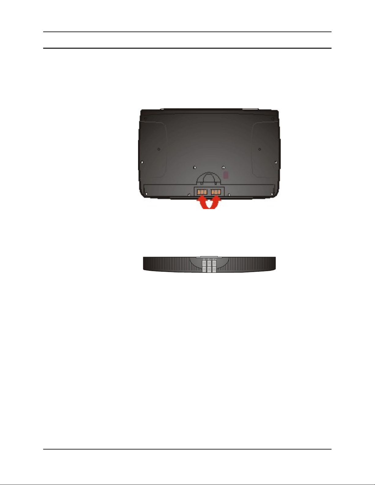
Figure 7 MX3-CE Battery Contacts
The MX3-CE Battery Compartment is located at the bottom of the back of the computer. The
arrows in the figure above point to the battery and cradle contacts in the computer.
Figure 8 Main Battery
Place the battery in the compartment, making sure the side of the battery with six contacts matches
up with the battery contacts in the computer battery compartment. Do not slide the battery
sideways into the compartment.
Firmly press the battery into the compartment until the Retaining Clip on the battery clicks. The
battery is now securely fastened to the MX3-CE.
E-EQ-MX3CEOGWW-F-ARC MX3-CE User’s Guide
Page 14
8 Quick Start
Power Button
Note: Refer to the section titled "Power Modes" in the MX3-CE Reference Guide for
information relating to the power states of the MX3-CE.
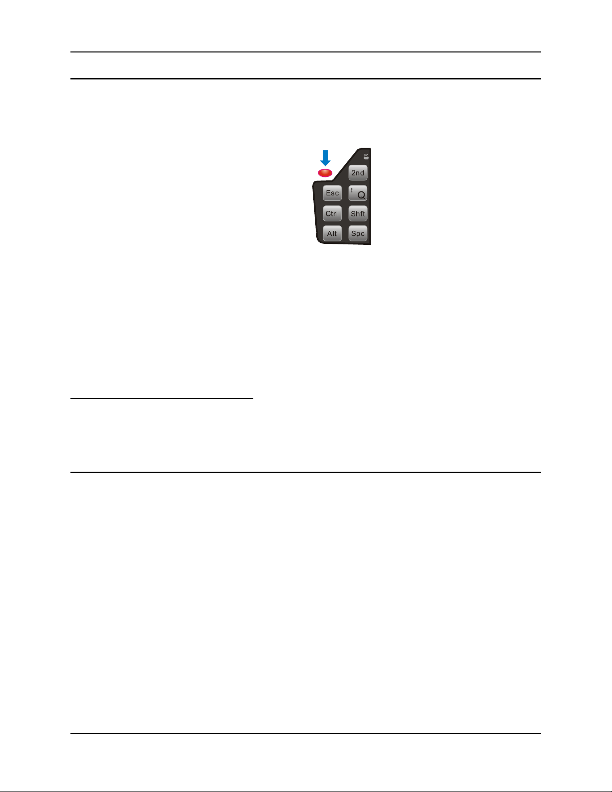
Figure 9 Power Button
The power button is located above the ESC key on the keypad. When a battery is inserted in the
MX3-CE for the first time press the Power button.
Quickly tapping the Power button places the MX3-CE immediately in Suspend mode. Quickly
tapping the Power button again, or touching the screen, immediately returns the MX3-CE from
Suspend.
Please refer to the section titled "Power Modes" in the MX3-CE Reference Guide for a list of the
kinds of activities (Primary Events) that will return the MX3-CE from Suspend Mode. Dimmed
primary events on the Primary Events screen in the Control Panel are non-functional.
Reboot Sequence
Hold the Power key down until the display goes out (15 seconds), then release the Power button.
When the WinCE desktop is displayed or an application begins, the power up (or reboot)
sequence is complete. If you have previously saved your settings, they will be restored on reboot.
Attach the Stylus Clip (Optional)
Carefully remove the paper backing from the Stylus Clip sticky. Firmly press the sticky side of the
clip onto the MX3-CE and hold in place for 15 seconds. Thread the tether through the end of the
stylus and tie the ends firmly to the Stylus Clip so that the ends don’t interfere with placing the
stylus in the Stylus Clip. Place the stylus in the Stylus Clip when not in use.
MX3-CE User’s Guide E-EQ-MX3CEOGWW-F-ARC
Page 15
Quick Start 9
Connect External Power Supply (Optional)
There are three external power supplies available:
• US AC/DC 12V Power Supply
• Cigarette Lighter Adapter
• International AC/DC 12V Power Supply
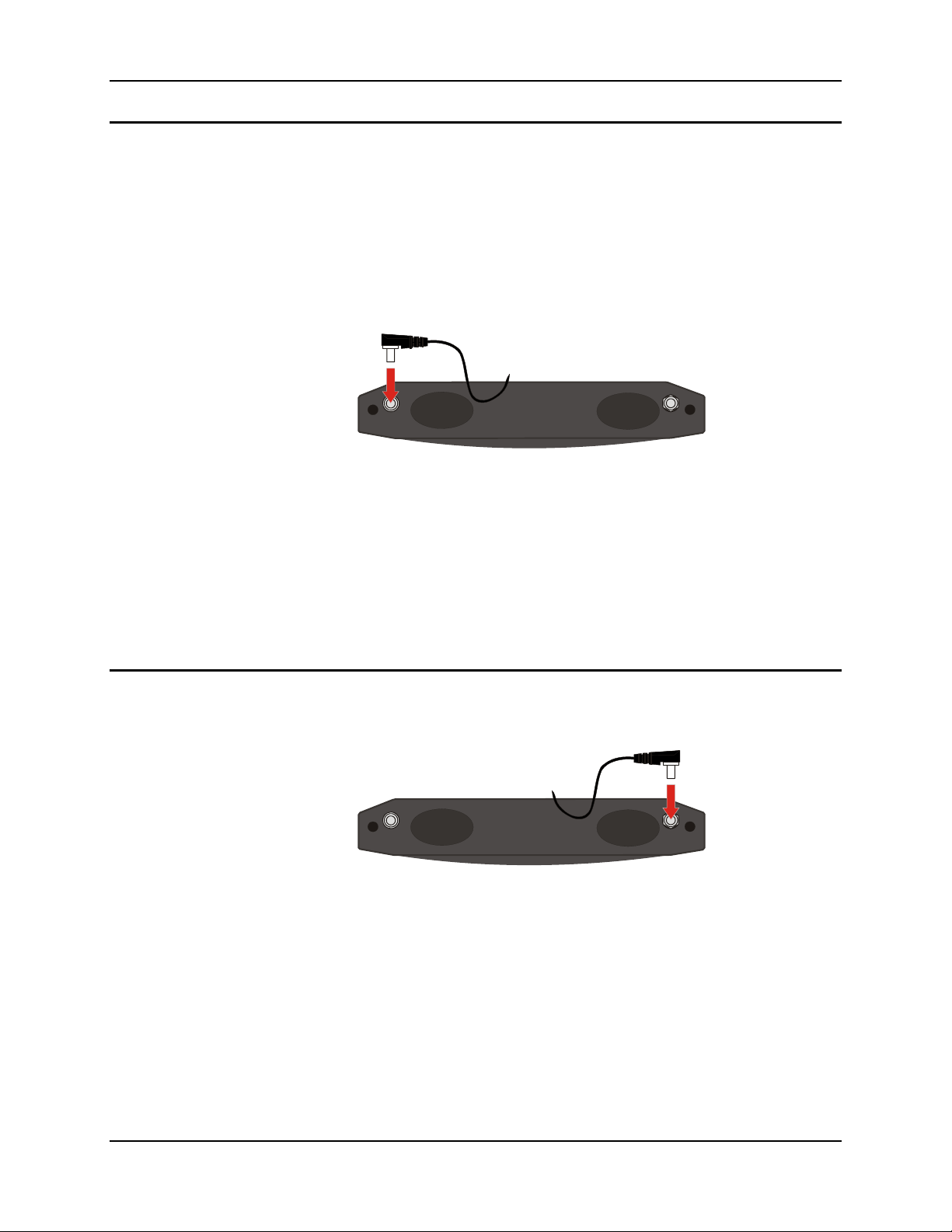
The MX3-CE DC power jack is located on the endcap. The cradle power jack is located on the
back of the cradle.
Figure 10 Connect External Power Supply
1. Insert the barrel connector into the MX3-CE power jack and push in firmly.
2. The CHGR LED above the keypad illuminates when the MX3-CE is receiving external
power through the power jack. The Main Battery recharges when the MX3-CE is
connected to an external power source.
Note: When the MX3-CE is receiving power through a cradle connected to external power, the
cradle's Status LED and the MX3-CE's CHGR LED are illuminated.
Connect Audio Jack (Optional)
The MX3-CE audio jack is located on the endcap.
Insert the barrel end of the connector into the MX3-CE audio jack and push in firmly.
Note: The audio option draws power from the Main Battery Pack.
Figure 11 Connect Audio Jack
E-EQ-MX3CEOGWW-F-ARC MX3-CE User’s Guide
Page 16
10 Quick Start
Attach Hand Strap (Optional)
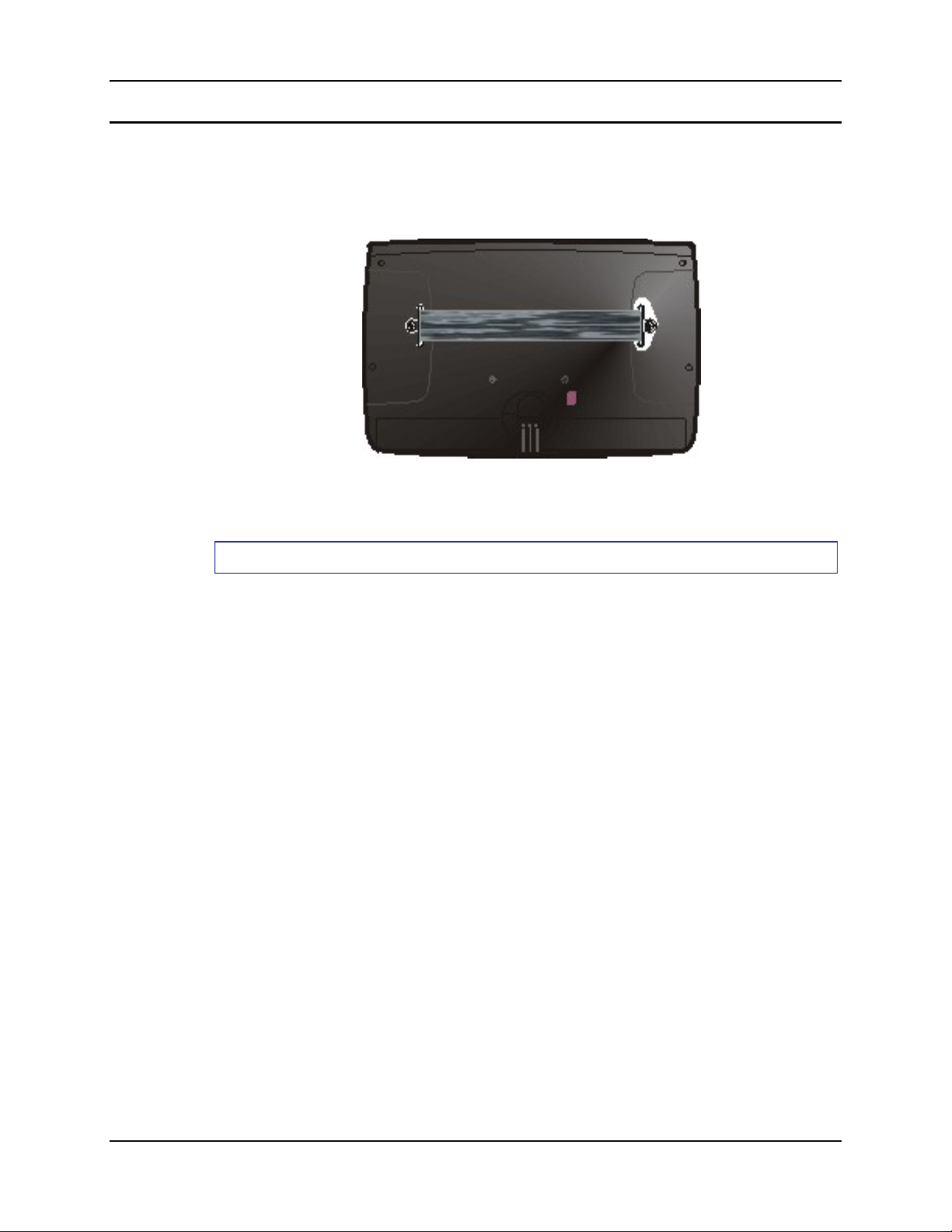
An elastic handstrap is available for the MX3-CE. Once installed, the handstrap provides a means
for the user to secure the computer to their hand. It is adjustable to fit practically any size hand
and does not interfere with battery charging when the MX3-CE is in a cradle.
Figure 12 MX3-CE With Handstrap Installed
Tool Required: #1 Phillips Screwdriver
Installation
1. Place the MX3-CE, with the screen facing down, on a flat stable surface.
2. Attach the hand strap to the MX3-CE with the screws and washers provided.
3. Test the strap's connection making sure the MX3-CE is securely connected to each end of the
strap.
Periodically check the hand strap for wear and the connection for tightness. If the hand strap gets
worn or damaged, it must be replaced.
MX3-CE User’s Guide E-EQ-MX3CEOGWW-F-ARC
Page 17

Quick Start 11
Tapping the Touchscreen with a Stylus
Note: Always use the point of the stylus for tapping or making strokes on the display. Never use
an actual pen, pencil or sharp object to write on the touch screen.
Hold the stylus as if it were a pen or pencil. Touch an element on the screen with the tip of the
stylus then remove the stylus from the screen. Firmly press the stylus into the stylus holder on the
MX3-CE when the stylus is not in use.
Like using a mouse to left-click icons on a computer screen, using the stylus to tap icons on the
MX3-CE display is the basic action that can:
• Open applications
• Choose menu commands
• Select options in dialog boxes or drop-down boxes
• Drag the slider in a scroll bar
• Select text by dragging the stylus across the text
• Place the cursor in a text box prior to typing in data or retrieving data using the integrated
barcode scanner or an input/output device connected to the serial port.
An extra or replacement stylus can be ordered from LXE. See the section titled "Accessories" for
the stylus part number.
Keypad Shortcuts
Use keyboard shortcuts instead of the stylus when the MX3-CE is running WinCE.
• Press Tab and an Arrow key to select a file.
• Press Shift and an Arrow key to select several files.
• Once you've selected a file, press Alt then press Enter to open its Properties dialog.
• Press 2
• Right mouse click – press the Alt key and then tap the screen. Select a menu option.
• To force the Start menu to display, press Ctrl then press Esc.
nd
then press numeric dot to delete a file.
E-EQ-MX3CEOGWW-F-ARC MX3-CE User’s Guide
Page 18
12 Quick Start
Set The Display Contrast
Adjusting screen contrast lightens or darkens the characters to make them visible at a comfortable
level. The contrast is incremented or decremented one step each time the contrast key is pressed.
To adjust screen contrast, locate the <F6> key at the top of the keypad. Adjust
the display contrast by pressing the:
nd
key1, then the <F6> key
• 2
• Use the Up Arrow and Down Arrow keys to adjust contrast until the display lightens or
darkens to your satisfaction.
• Press the Enter key to exit this mode.
Set the Display Backlight Timer
Note: Refer to the section titled "Power Modes" in the MX3-CE Reference Guide for
information relating to the power states of the MX3-CE.
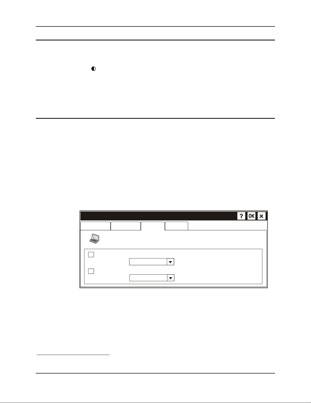
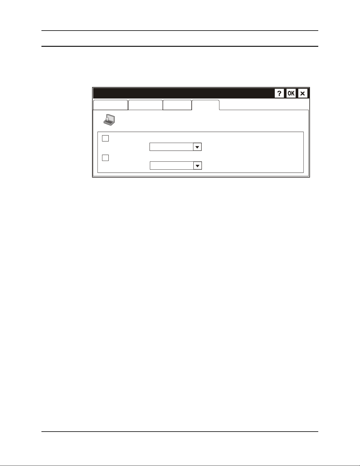
Select Start | Settings | Control Panel | Display | Backlight tab. Change the parameter values
and tap OK to save the changes.
The first option may be set when the MX3-CE will be running on battery power only. The second
option may be set when the MX3-CE will be running on external power (e.g. AC adapter,
cigarette adapter, powered cradle).
The default value for the battery power timer is 3 seconds. The default value for the external
power timer is 2 minutes. The backlight will remain on all the time when both checkboxes are
blank.
Display Properties
Background
Automatically turn off backlight while on battery power.
Turn off after
Automatically turn off backlight while on external power.
Turn off after
Appearance
To save battery life, you can adjust when the backlight automatically
shuts off.
Backlight
Blanking
of continuous idle time.
of continuous idle time.
Figure 13 Display Properties / Backlight
This option is also available by selecting Start | Settings | Control Panel | Power | Backlight
tab.
The transmissive color display backlight timer dims the backlight at the end of the specified time.
The transflective monochrome and color display backlight timer turns the backlight off at the end
of the specified time.
1
The LED for this key blinks until the special editing mode (set volume or contrast) is complete.
MX3-CE User’s Guide E-EQ-MX3CEOGWW-F-ARC
Page 19
Quick Start 13
Set the Display Blanking Timer
Note: Refer to the section titled "Power Modes" in the MX3-CE Reference Guide for
information relating to the power states of the MX3-CE.
Display Properties
Background
Automatically blank display while on battery power.
Blank after
Automatically blank display while on external power.
Blank after
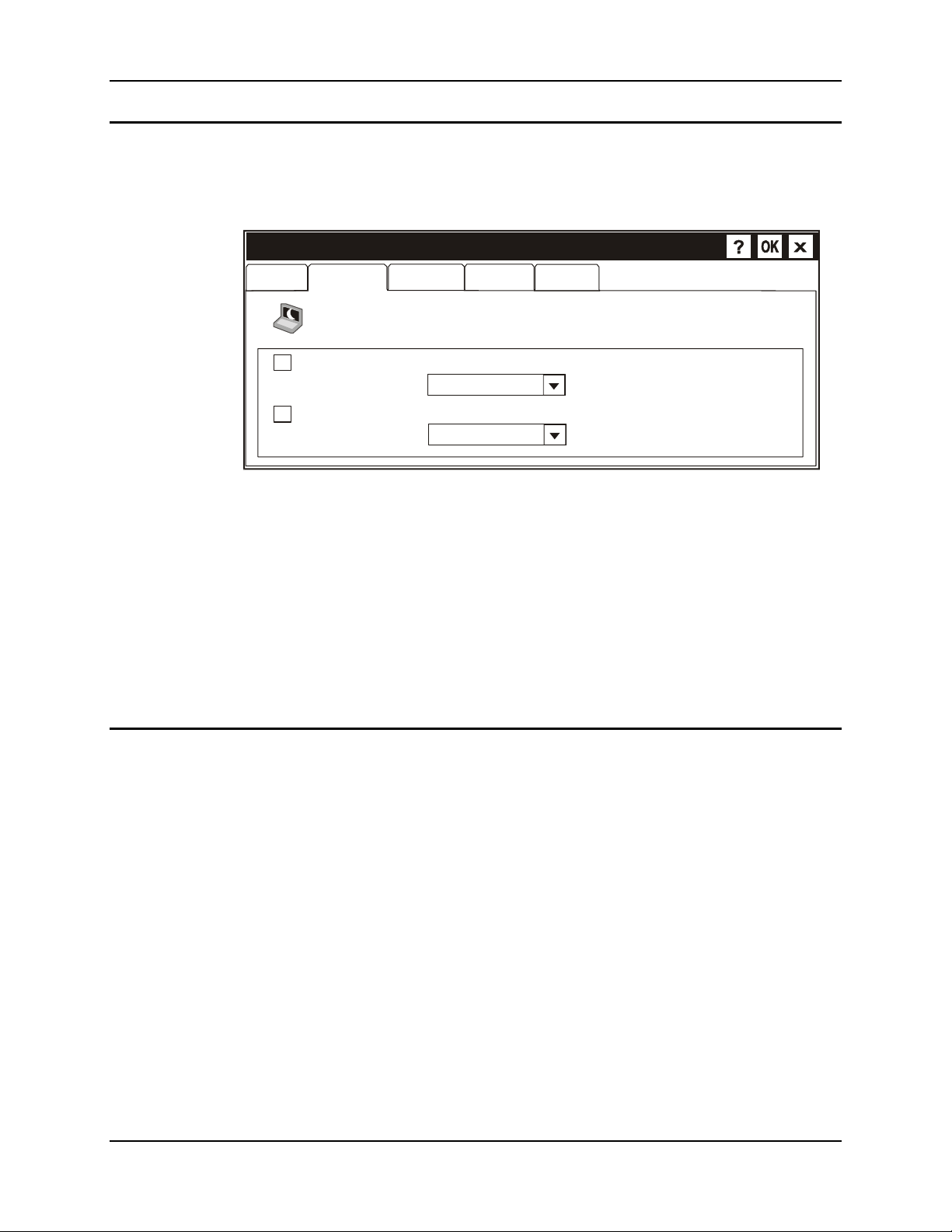
Select Start | Settings | Control Panel | Display | Blanking tab. This option is also available by
selecting Start | Settings | Control Panel | Power | Blanking tab. Change the parameter values
and tap OK to save the changes.
The first option may be set when the MX3-CE will be running on battery power only. The second
option may be set when the MX3-CE will be running on external power (e.g. AC adapter,
cigarette adapter, powered cradle).
The default value for the battery power timer is 15 seconds. The default value for the external
power timer is 2 minutes. The display will remain on all the time when both checkboxes are
blank.
Appearance
To save battery life, you can adjust when the display automatically
blanks.
Figure 14 Display Properties / Blanking Timer
Backlight
Blanking
of continuous idle time.
of continuous idle time.
E-EQ-MX3CEOGWW-F-ARC MX3-CE User’s Guide
Page 20
14 Quick Start
Set the MX3-CE Power Off Timer
Note: Refer to the section titled "Power Modes" in the MX3-CE Reference Guide for
information relating to the power states of the MX3-CE.
Power Properties
Battery
Select Start | Settings | Control Panel | Power | Power Off tab. Change the parameter values
and tap OK to save the changes.
The first option may be set when the MX3-CE will be running on battery power only. The second
option may be set when the MX3-CE will be running on external power (e.g. AC adapter,
cigarette adapter, powered cradle).
The default value for both timers is 5 minutes. The computer will remain on (not in Suspend
Mode) all the time when both checkboxes are blank.
Note: When the Power Off timer expires, the computer enters Suspend Mode.
Power Off
Save battery power and prevent unauthorized use (in conjunction
with a password) by having your device turn off when not in use .
Enable suspend while on battery power.
Suspend after
Enable suspend while on external power.
Suspend after
Backlight
Blanking
Figure 15 Power Off Timer
Charge
of continuous idle time.
of continuous idle time.
Saving Settings
To preserve configuration settings to non-volatile memory, tap the Start menu button, select
"Run".
In the dialog box that pops up, type "RegSave" and tap Enter (or click the arrow on the popup
box, select RegSave from the list, and tap Enter).
The cursor changes to an hourglass for a moment, then a dialog appears indicating the
configuration has been saved.
The save process takes 10-15 seconds. After this, these settings are reloaded every time the unit
reboots.
MX3-CE User’s Guide E-EQ-MX3CEOGWW-F-ARC
Page 21
Quick Start 15
Set The Audio Speaker Volume
Note: An application may override the control of the speaker volume. Turning off sounds saves
power and prolongs battery life.
The audio volume can be adjusted to a comfortable level for the user. The volume is increased or
decreased one step each time the volume key is pressed. The MX3-CE has an internal speaker and
a jack for an external headset.
Using the Keypad
Note: Volume & Sounds (in Control Panel) must be enabled before the following key sequences
will adjust the volume.
To adjust speaker volume, locate the <F8> key at the top of the keypad. Adjust
the speaker volume by pressing the:
nd
• 2
key2, then the <F8> key to enter Volume change mode.
• Use the Up Arrow and Down Arrow keys to adjust volume until the speaker volume is
satisfactory.
• Press the Enter key to exit this mode.
Using the Touch Screen
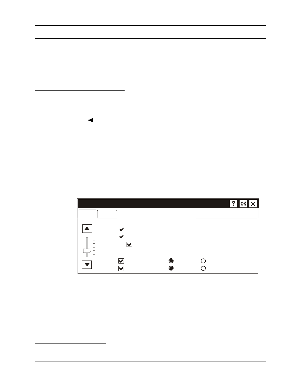
Select Start | Settings | Control Panel | Volume & Sounds | Volume tab. Change the volume
setting and tap OK to save the change. You can also select / deselect sounds for key clicks and
screen taps and whether each is loud or soft.
V o lu me & Sounds Properties
Volume
Loud
Soft
As the volume scrollbar is moved between Loud and Soft, the computer will emit a beep each
time the volume increases or decreases in decibel range.
Sounds
Enable sounds for:
Events (warnings, beeps and system eve nt s)
Applications (program specific and all other sounds)
Notifications (alarms, appointments and reminders)
Enable clicks and taps for:
Key clicks:
Screen taps:
Figure 16 Adjust Audio Volume
Loud
Loud
Soft
Soft
2
The LED for this key blinks until the special editing mode (set volume or contrast) is complete.
E-EQ-MX3CEOGWW-F-ARC MX3-CE User’s Guide
Page 22

16 Quick Start
Enter Data
You can enter data into the MX3-CE through several different methods. The Scanner window
provides barcode data entry, the RS-232 or the IR port are used to input/output data, and the
keypad provides manual entry.
MX3-CE's with a touch screen and Microsoft WindowsCE software can use a stylus to input data,
the COM ports and/or the keypad.
Keypad Entry
The keypad is used to manually input data that is not collected otherwise. Almost any function
that a full sized computer keyboard can provide is duplicated on the MX3-CE keypad but it may
take a few more keystrokes to accomplish a keyed task.
Almost every key has two or three different functions. The primary alpha or numeric character is
printed on the key.
For example, when the 2nd key is selected pressing the desired second-function key will produce
the 2nd character. The specific 2nd character is printed above the corresponding key. The 2
LED will illuminate and turn off after the next keypress (unless when setting volume or contrast –
the 2
Please refer to “Appendix A - Key Maps” for instruction on the specific keypresses to access all
keypad functions.
Stylus Data Entry
Note: This section is directed to the MX3-CE user. The assumption is that the unit has been
Note: Always use the point of the stylus for tapping or making strokes on the display. Never use
The stylus performs the same function as the mouse that is used to point to and click elements on
a desk top computer. The stylus is used in the same manner as a mouse – single tap or double tap
to select menu options, drag the stylus across text to select, hold the stylus down to activate slider
bars, etcetera.
Hold the stylus as if it were a pen or pencil. Touch an element on the screen with the tip of the
stylus then remove the stylus from the screen. The touch screen responds to an actuation force
(touch) of 4 oz. (or greater) of pressure.
The stylus can be used in conjunction with the keyboard and scanner and an input/output device
connected to one of the MX3-CE's serial ports.
nd
key LED will flash at those times).
configured and the touch panel calibrated by the System Administrator prior to releasing
the MX3-CE for daily use. The touch screen should be calibrated before initial use.
an actual pen, pencil or sharp object to write on the touch screen.
nd
key
• Touch the stylus to the field of the data entry form to receive the next data feed.
• The cursor begins to flash in the field.
• The unit is ready to accept data from either the keyboard, integrated scanner or a scanner
connected to the serial port, if the scanner applet is configured correctly.
MX3-CE User’s Guide E-EQ-MX3CEOGWW-F-ARC
Page 23
Quick Start 17
Scanner Entry
Read all cautions, warnings and labels before using the laser
scanner.
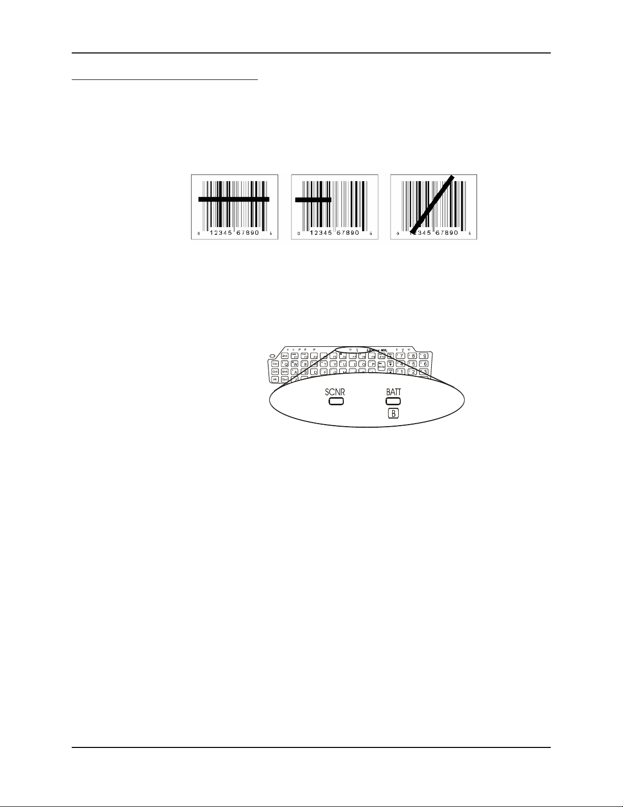
To scan with the laser barcode reader, point the laser window towards a barcode and press the
Scan button. You will see a red laser beam strike the barcode.
Correct Scan Incorrect Scan Incorrect Scan
Figure 17 Scan Beam
Align the red beam so that the barcode is centered within the beam. The laser beam must cross the
entire barcode. Move the MX3-CE towards or away from the barcode so that the barcode takes up
approximately two-thirds the width of the beam.
Figure 18 Scanner LED Location
The SCNR LED turns red when the laser beam is on. Following a barcode scan and read the
SCNR LED turns green and the MX3-CE beeps, indicating a successful scan.
The laser and SCNR LED automatically turn off after a successful or unsuccessful read. The
scanner is ready to scan again when the Scan key is pressed.
E-EQ-MX3CEOGWW-F-ARC MX3-CE User’s Guide
Page 24
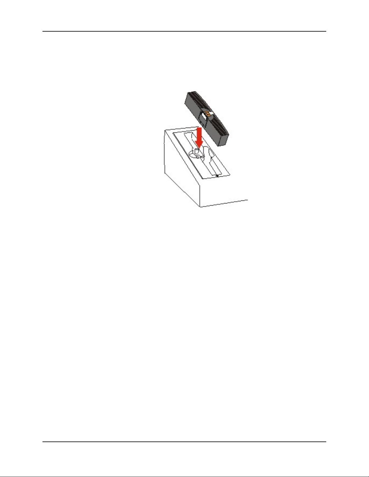
18 Charge Battery in MX3 Multi-Charger
Charge Battery in MX3 Multi-Charger
The Main Battery can be charged in the MX3 Multi-Charger. The Main Battery charges the
Backup Battery.
Figure 19 Insert Main Battery in Charging Cup
Insert the Main Battery into any charging cup in the Multi-Charger. The retaining clip will snap
the battery into place in the charging cup.
Do not "slam" or slide the battery into the charging cup.
Failure to follow these instructions can result in damage to the main battery or the Multi-Charger.
MX3-CE User’s Guide E-EQ-MX3CEOGWW-F-ARC
Page 25

Getting Help 19
Getting Help
All LXE user guides are now available on one CD and they can also be viewed/downloaded from
the LXE ServicePass website. Contact your LXE representative to obtain the LXE Manuals CD.
You can also get help from LXE by calling the telephone numbers listed on the LXE Manuals
CD, in the file titled "Contacting LXE". This information is also available on the LXE website
www.lxe.com.
Explanations of terms and acronyms used in this guide are located in the file titled "LXE
Technical Glossary" on the LXE Manuals CD.
Manuals
MX3-CE Reference Guide
MX3 Cradle Reference Guide
MX3 Multi-Charger User's Guide
MX3 Multi-Charger Plus User's Guide
Accessories
Tethered Scanners
Scanner, LS3203, Ext. Range, 8’ Cbl, US. 8011LS3203ERC08DUS (Obsolete)
Scanner, LS3203, Ext. Range, 8’ Cbl, EC. 8011LS3203ERC08DEC (Obsolete)
Scanner, LS3203, Ext. Range, 20’ Cbl, US 8011LS3203ERC08DUS (Obsolete)
Scanner, 530092IP, 7’ Cbl, WW. 8110IP530092C07DWW (Obsolete)
Scanner, 530092IP, 15’ Cbl, US. 8110IP530092C15DUS (Obsolete)
Scanner, P302FZY, 8’ Cbl, WW 8200A326SCNRP3028DA9F (Obsolete)
Scanner, P302FZY, 20’ Cbl, US 8200A327SCNRP30220DA9F (Obsolete)
Scanner, P304PRO, 8’ Cbl, WW 8210A326SCNRP3048DA9F (Obsolete)
Scanner, P304PRO, 8’ Cbl, US 8210A327SCNRP30420DA9F (Obsolete)
Scanner, Powerscan SR, 8’ Cbl, WW 8300A326SCNRPWRSR8DA9F
Scanner, Powerscan SR, 12’ Cbl, US 8300A327SCNRPWRSR12DA9F
Scanner, Powerscan LR, 8’ Cbl, WW 8310A326SCNRPWRLR8DA9F
Scanner, Powerscan LR, 12’ Cbl, US 8310A327SCNRPWRLR12DA9F
Scanner, Powerscan XLR, 8’ Cbl, WW 8320A326SCNRPWRXLR8DA9F
Scanner, Powerscan XLR, 12’ Cbl, US 8320A327SCNRPWRXLR12DA9F
PCMCIA Cards
Standard Compact Flash Card, 1Gig HD 9000A254HDDCF1GB
PCMCIA Compact Flash Adapter 9000A106PCCCFADPTR
Holding Accessories
Strap, Hand, Nylon 2381A497HANDSTRAP
Nylon Holster for use with Belt 2381A401HOLSTER
Nylon Hip Flip 9000A408HIPFLIP
Adjustable Belt for Hip Flip, Velcro ends 9200L67
Nylon Case with Shoulder Strap 9000A409CASE
Stand, Scanner For 5300IP Series, Tethered 8100A001STAND (Obsolete)
Bracket, Mounting LS300 8010A001BRKT (Obsolete)
Holster, Hood, Nylon, 5300IP Series, Tethered 8100A401HLSTRHOOD (Obsolete)
E-EQ-MX3CEOGWW-F-ARC MX3-CE User’s Guide
Page 26

20 Getting Help
Miscellaneous
Pen, Stylus, Black, 2330 9000A501PASSIVEPEN
Headset with microphone 9000A503HEADSET
Battery Chargers and Battery
6 Unit Charger 9000A377CHGR6*
Battery, Li-Ion MX3A378BATT
Cradles and Power Supplies
3
Desktop Cradle
Vehicle Mount Cradle
Vehicle Mount Cradle, 19.2K Baud Rate
Power Supply, Vehicle Cradle, 9-30VDC 2381A054CRDLDCPWR30V
Power Supply, Vehicle Cradle, 30-80VDC 2381A055CRDLDCPWR80V
AC Power Supply, External, US 9000A301PSACUS
AC Power Supply, External, AC, International 9000A302PSACWW
Power Cord, AC, US 9000A066CBLPWRAC
P/S, External, Cigarette Lighter Adapter 9000A303PSCIGLTADPT
Power Adapter, Bare Wire 12 VDC 1300A053CBL12ML3
Power Adapter, 24-72 VDC, 20 Watts 9000A316PS24V72VMX13
Power Adapter, 110-240 VAC 1300A303PSACWW
2381A001DESKCRADLE
3
2381A003VMCRADLE
3
9000A005VMCRADLE19KB
Cables for Cradle and MX3-CE Serial Ports
Cable, PC, DA-9F to DA-9F, 6 ft. for download 9000A054CBL6D9D9
USB cable 9000A067CBL48D9USB
Cable, D9F to D25F, for printer 9000A053CBL6D9D25
Either US or WW
Note: When using the 8500 Series tethered scanners (LS3408), the tethered scanner Power Mode must be
set to “Reduced Power Mode”to conserve MX3-CE battery life. The reduced power mode setting will not
impact performance of the 8500 series scanner. The default mode is “Continuous On”. Please refer to the
manufacturer’s user guide for instruction.
3
Power Adapter Required.
MX3-CE User’s Guide E-EQ-MX3CEOGWW-F-ARC
Page 27
Touch Screen Display
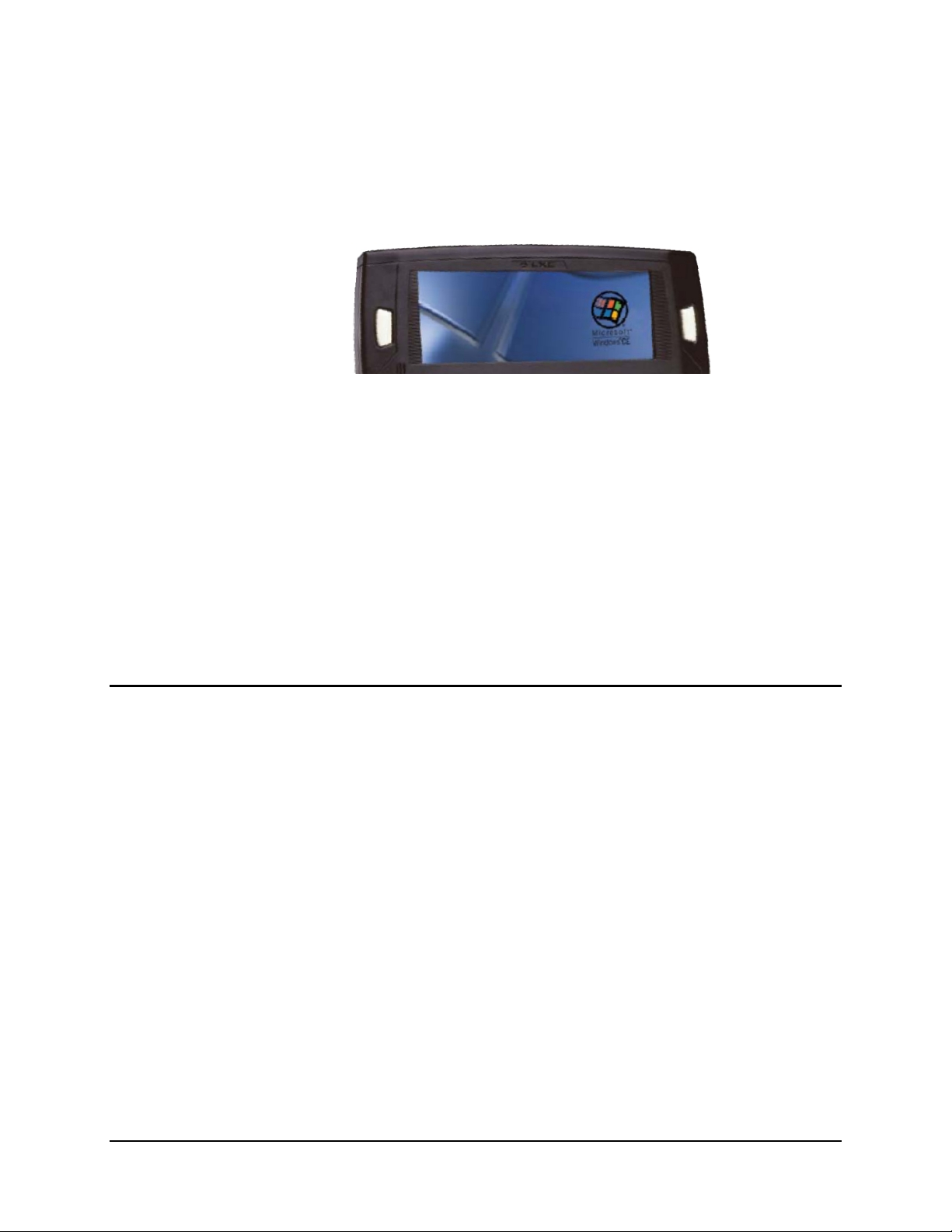
The MX3-CE Touch Screen Display is an LCD unit capable of supporting VGA graphics modes.
Display size is 640 x 240 pixels. The display covering is designed to resist stains. The touch
screen allows signature capture and touch input. A pen stylus is included. The touch screen
responds to an actuation force (touch) of 4 oz. of pressure (or greater).
The MX3-CE Hand Held Computer
Figure 20 MX3-CE Touch Screen Display
There are three types of displays available: transflective greyscale monochrome; transmissive
color and transflective color. The transmissive color display is optimized for indoor lighting. It
cannot be used without the backlight. The transflective monochrome and color display are
optimized for outdoor use but may also be used indoors. The monochrome display has an
electroluminescent backlight. The color displays have a CCFL (Cold-Cathode Fluorescent
Lighting) backlight.
The transflective display appears to have a greenish hue when the display is blanked. The
transmissive display appears black when the display is blanked.
Display Backlight
The Display backlight is turned on when the unit returns from Suspend Mode. The display
backlighting feature is programmable and activates based on power source and amount of idle
time before entering the Suspend state.
See the section titled "Set the Display Backlight Timer " in the previous section "Quick Start."
E-EQ-MX3CEOGWW-F-ARC MX3-CE User’s Guide
Page 28
22 Touch Screen Display
Touch Screen Calibration
If the MX3-CE is not responding properly to pen touch taps, the touch screen may need to be
recalibrated. Contact your System Administrator for assistance.
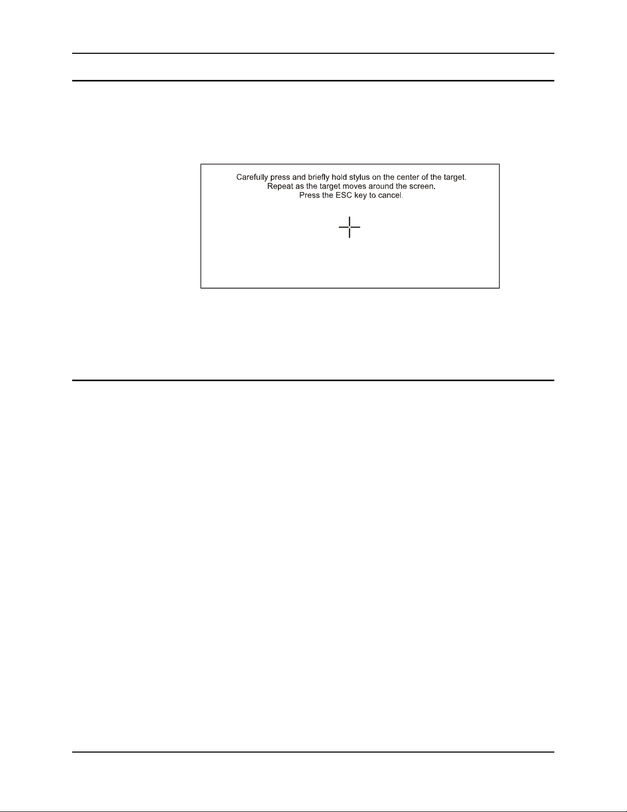
To recalibrate the screen, select Start | Settings | Control Panel | Stylus | Calibration.
Figure 21 Touch Screen Recalibration
To start, tap Recalibrate. Follow the instructions on the screen and press the Enter key to save the
new calibration settings or press Esc to cancel or quit.
See the "MX3-CE Reference Guide" for complete instructions.
Cleaning the Glass Display/Scanner Aperture
Keep fingers and rough or sharp objects away from the scan aperture and display. If the glass
becomes soiled or smudged, clean only with a standard household cleaner such as Windex(R)
without vinegar or use Isopropyl Alcohol. Do not use paper towels or harsh-chemical-based
cleaning fluids since they may result in damage to the glass surface. Use a clean, damp, lint-free
cloth. Do not scrub optical surfaces. If possible, clean only those areas which are soiled.
Lint/particulates can be removed with clean, filtered canned air.
MX3-CE User’s Guide E-EQ-MX3CEOGWW-F-ARC
Page 29
Programmable Buttons 23
Programmable Buttons
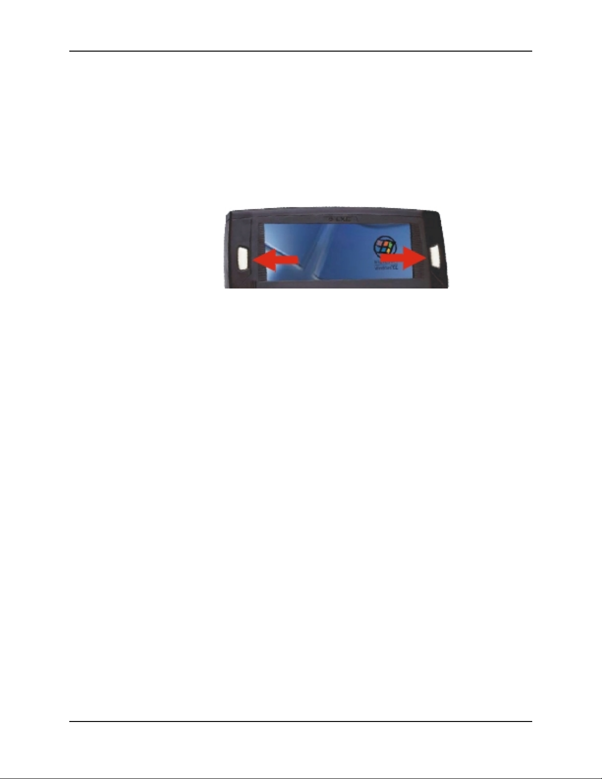
The default setting for the right button is Enter. The default setting for the left button is Scan.
When the MX3-CE does not have an integrated scanner, both buttons function as Enter keys.
Scan Pressing this key activates the integrated laser scanner, if installed. See the section
titled "Scan Key Function."
Enter Pressing this key confirms a forms entry or transmits information. See the section
titled "Enter Key Function."
Figure 22 Programmable Buttons (Scan / Enter)
The buttons to the left and right of the display can each be programmed by the System
Administrator (using the Scanner Control Panel) to perform the following functions:
• Disabled – no response when pressed
• Scan – initiate a barcode scan sequence
• Enter Key
• Tab Key
• Virtual Key
To edit the button parameters, select Start | Settings | Control Panel | Scanner | Keys. Change
the parameter values and tap OK to save the changes.
See the "MX3-CE Reference Guide" for complete instructions.
E-EQ-MX3CEOGWW-F-ARC MX3-CE User’s Guide
Page 30
24 Endcaps and COM Ports
Endcaps and COM Ports
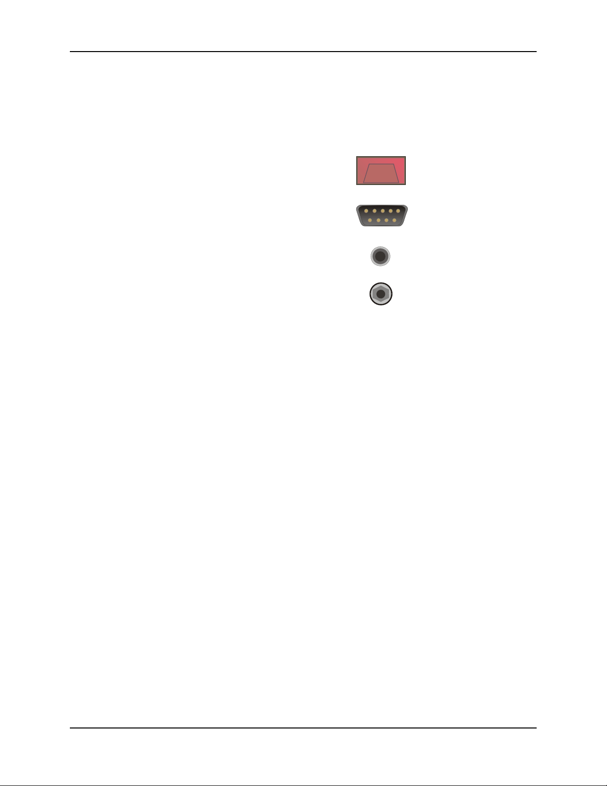
The MX3-CE supports three COM port options. Two external serial ports are dependent on the
end cap chosen. A third serial port is used to support an infrared transciever (barcode reader). An
additional endcap configuration supports serial and USB “slave” input/output at 1.5 MBps.
Scanner Port
RS-232 Port (Serial Port)
and/or USB Host
Audio Jack
DC Power Jack
Figure 23 Endcap Connectors
The COM 2 port is always the IR port on the back of the MX3-CE, regardless of the type of
endcap installed. COM 2 can only be accessed when a tethered scanner is connected to the RS232 port on the cradle, and the MX3-CE is in the cradle. The cradle does not need to be powered
by an alternate AC or DC power source. Tethered scanners receive power from the MX3-CE's
Main Battery.
On the Standard Range Scanner / Serial Port endcap COM 3 is the Integrated Scanner port. The
integrated barcode scanner scans only when the MX3-CE Scan button is pressed. To edit Scanner
Com Port parameters, select Start | Settings | Control Panel | Scanner. Change the parameter
values and tap OK to save the changes.
On the Dual Serial Port endcap the COM1 port is the serial port on the right side of the endcap
when the display is facing you.
MX3-CE User’s Guide E-EQ-MX3CEOGWW-F-ARC
Page 31
IR Port 25
Tethered Scanners
The MX3-CE Scan buttons have no effect on tethered barcode scanners (connected to a serial
port). Tethered scanners read barcode scans only when the trigger on the tethered scanner is
pressed. To set the MX3-CE to use a tethered scanner, select Start | Settings | Control Panel |
Scanner | COM1 (2 or 3). Click the "Power on Pin 9 (+5V)" checkbox for the COM port
selected.
Please refer to the tethered scanner manufacturer’s guide for instruction when using the
tethered scanner with the MX3-CE.
USB Port
The USB port requires a DB9 to USB cable (available from LXE). The serial port/USB port also
supports serial data transfer (using a null modem cable) and non-host USB I/O at 1.5 Mbps. The
MX3-CE automatically detects the cable configuration. Refer to section titled "Accessories" in
this manual for part numbers for the DB9-USB cable and the null modem cable.
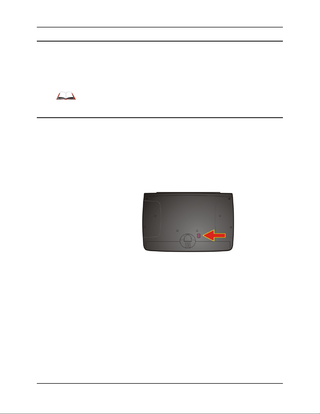
IR Port
Figure 24 IR Port (COM 2)
The InfraRed (IR) port provides a means of transferring information to a device with a similar
port and the proper software. The IR port can be used to communicate with printers or a host
computer with the use of an adapter.
The IR Port is specified as COM 2 and is a bi-directional half-duplex infrared port. It supports the
Slow IrDA (Infrared Data Access) PHY Layer standard that allows communication speeds up to
115k baud.
When sending data through the IR port to another MX3-CE's IR port, make sure both units are in
close proximity to each other. The IR operating envelope has a distance range of 2 cm (.79 inches)
to 1 meter (3.2 feet) with a viewing angle of 30 degrees.
See the "MX3-CE Reference Guide" for complete instructions.
E-EQ-MX3CEOGWW-F-ARC MX3-CE User’s Guide
Page 32
26 The Keypad
The Keypad
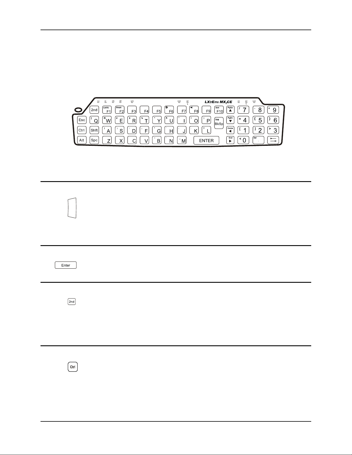
The QWERTY keypad is phosphorescent. A phosphorescent keypad does not use a keypad
backlight but glows in dim/dark areas after exposure to a light source.
The keypad is installed and configured by LXE.
Figure 25 The QWERTY Keypad
The keymaps (keypress sequences) are located in “Appendix A - Key Maps.”
Scan Key Function
(MX3-CE's with Scanner endcaps only.) The Scan key activates the scanner when a
scanner endcap is installed and the Scan button is pressed. The internal scanner scans
only when the Scan button is pressed. A Scan button press has no effect on externally
attached scanners. See previous section titled "Programmable Buttons."
When there is no integrated scanner endcap, the Scan keys function as Enter keys.
Enter Key Function
The Enter key is used to confirm a forms entry or to transmit information. How it is used is
determined by the application running on the computer.
2nd Key Function
The 2nd key is used to activate the 2
upper left corner are small characters that represent the 2
key activates the second key function. Note that the 2
Each time you need to use the 2
before pressing another key, press the 2
LED illuminates.
Ctrl Key Function
The Ctrl key enables the control functions of the keypad. This function is similar to a regular
keyboard’s Control key. Note that the Ctrl key only stays active for one keystroke. Each time
you need to use a Ctrl function, you need to press the Ctrl key before pressing the desired key.
When the Ctrl function is active, the Ctrl LED illuminates.
nd
functions of the keypad. Printed on many keys at the
nd
function you must press the 2nd key. To cancel a 2nd function
nd
key again. When the 2nd function is active, the 2nd
nd
function of that key. Using the 2nd
nd
key only stays active for one keystroke.
MX3-CE User’s Guide E-EQ-MX3CEOGWW-F-ARC
Page 33
The Keypad 27
Alt Key Function
The Alt key enables the alternate functions of the keypad. This function is similar to a regular
keyboard’s Alt key. Note that the Alt key only stays active for one keystroke. Each time you
need to use an alternate function, you need to press the Alt key before pressing the desired key.
When the Alt function is active, the Alt LED illuminates.
Shft Key Function
The Shft key enables the shifted functions of the keypad. This function is similar to a regular
keyboard’s Shift key. Note that the Shift key only stays active for one keystroke. Each time you
need to use a Shifted function, you need to press the Shft key before pressing the desired key.
When the Shft function is active, the Shft LED illuminates.
When the Shft key is pressed the next key is determined by the major key legends, i.e., the
alpha keys display lower case letters -- when CAPS is On alpha characters are capitalized. For
example, when CAPS is on and the Shft key and the G key are pressed, a lower case g is
displayed.
Spc Key Function
The Spc key adds a space to the line of data on the display. This function is similar to a regular
keyboard’s Spacebar. Note that the Spc key only stays active for one keystroke.
Mode Key Functions
Caps Key and CapsLock Mode
This function is similar to a regular keyboard’s CapsLock key. Note that the CapsLock mode stays
active until the CapsLock key sequence is pressed again. Each time you need to use a Caps
function, you need to press the Caps key sequence first. To cancel a CapsLock function press the
Caps key sequence again. When the CapsLock mode is active, the Caps LED illuminates.
The CapsLock key sequence is 2
• No CapsLock AND No Shift keypress – result is a lowercase letter.
• CapsLock OR Shift – result is an uppercase letter.
• CapsLock AND Shift keypress – result is a lowercase letter.
Keypress Sequences
See Appendix A for key maps for all keypads.
nd
+ F1.
E-EQ-MX3CEOGWW-F-ARC MX3-CE User’s Guide
Page 34
28 The Keypad
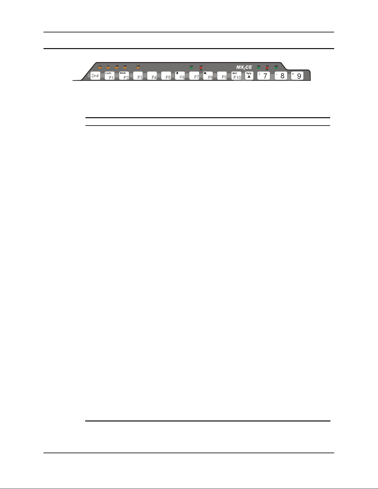
Keypad LED Functions
Figure 26 Function LEDs
Across the top of the keypad are LEDs that provide visual cues to current computer operation.
When the LED is not illuminated, the function is inactive.
LED When illuminated ...
2nd
The next keypress is a 2
• Orange when on, blinks until key sequence is completed and unlit when off.
nd
keypress.
ALT
CTRL
SHFT
CAPS
SCNR
BATT
B
STAT
The next keypress is an ALT keypress.
• Orange when on and unlit when off.
The next keypress is a CTRL keypress.
• Orange when on and unlit when off.
The next letter is the uppercase letter on alpha keys and the shifted character on the
numeric keypad keys.
• Orange when on and unlit when off.
Uppercase letters are active until the CAPS key sequence is pressed again.
• Orange when on and unlit when off.
Barcode scanner function, affected by both tethered scanners and the scanner
endcap.
• Red - scanning.
• Green - good scan.
• Unlit - scanner is inactive.
Backup Battery. When illuminated, the backup battery is charging. When unlit, the
Backup Battery is not charging
Status Indicator.
• Blinking Green when display Suspend state begins.
BATT
M
CHGR
Main Battery. When illuminated, main battery capacity is low.
• Red – low battery.
• Blinking Red – power fail.
• Unlit - Main Battery is fully charged.
Charger. When on, the MX3-CE is receiving external power either from the DC
power jack or the MX3-CE is seated in a powered cradle.
• Red - Main Battery is charging.
• Green - battery charge is complete and the MX3-CE is connected to external
power through the power jack or a powered cradle.
MX3-CE User’s Guide E-EQ-MX3CEOGWW-F-ARC
Page 35
Batteries 29
Batteries
Note: New batteries must be charged prior to use.If the Main Battery and Backup Battery are
depleted, the computer reverts to default values. RF configuration parameters will need
to be re-entered when the depleted Main Battery is replaced. The Backup Battery is
eventually recharged by the Main Battery.
The MX3-CE computer is designed to work with a Lithium-Ion (Li-ion) battery from LXE. Under
normal conditions it should last approximately eight to ten hours before requiring a recharge. The
more you use the scanner or the RF transmitter, the shorter the time required between battery
recharges. The MX3-CE keeps date and time valid for a minimum of four days using a fully
charged Backup Battery and a Main Battery that has reached the Low Warning point.
Main Battery
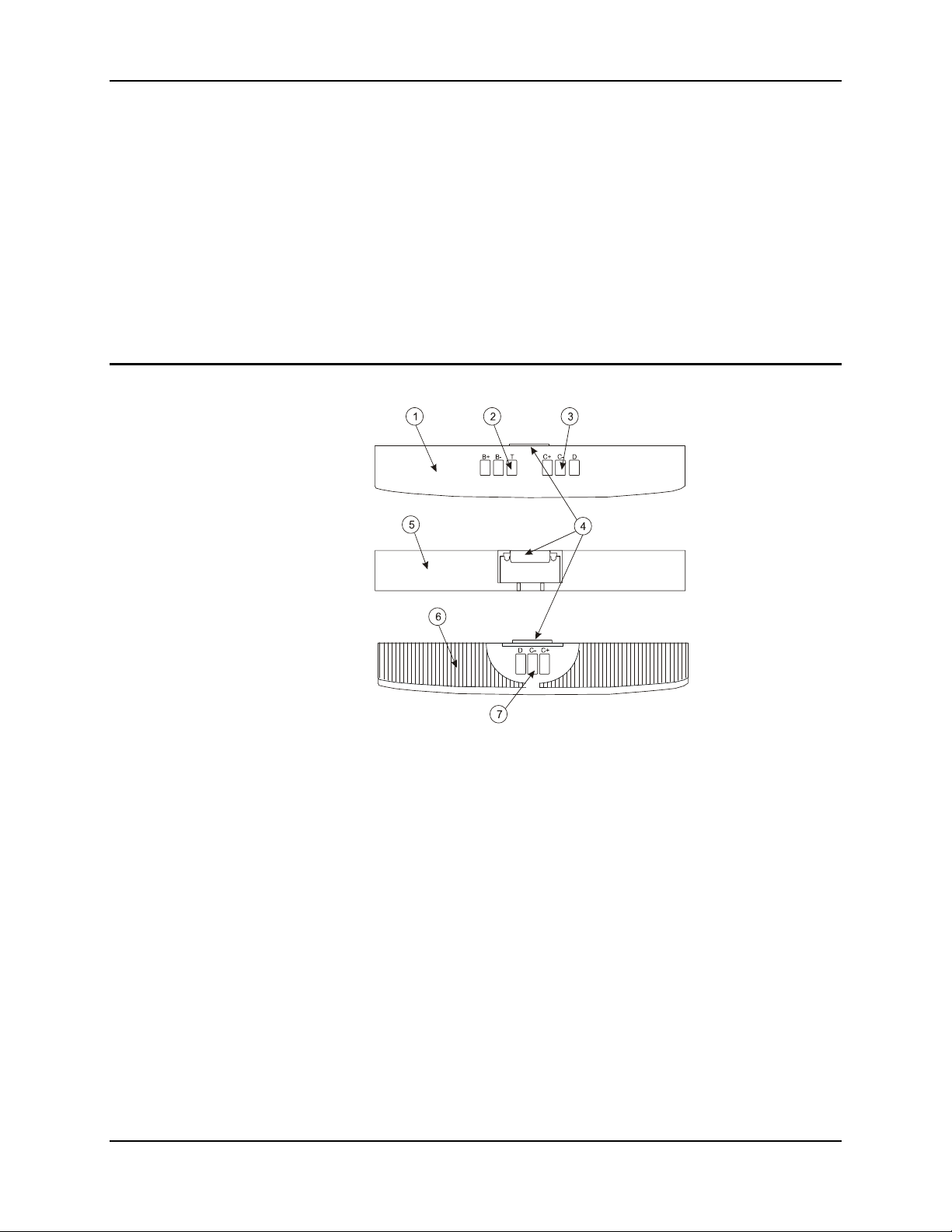
Figure 27 Main Battery
1 Front Side
2 Contacts, Main Battery
3 Contacts, Cradle Output
4 Retaining Clip
5 Top Side
6 Back Side
7 Contacts, Cradle Input
The main battery has a rugged plastic enclosure that is designed to withstand the ordinary rigors
of an industrial environment. Exercise care when transporting the battery making sure it does not
come in contact with excessive heat or any power source other than an LXE MultiCharger or
MX3-CE unit.
E-EQ-MX3CEOGWW-F-ARC MX3-CE User’s Guide
Page 36

30 Batteries
Backup Battery
The internal Nickel Cadmium (NiCd) backup battery provides power to the unit for a short
amount of time when the main battery has been depleted, removed or has failed. The backup
battery requires no user intervention. Replacement is performed by LXE.
Note: An uninterrupted external power source (wall AC adapters or DC/DC converters)
transfers power to the MX3-CE internal charging circuitry which, in turn, recharges the
Main Battery and Backup Battery.
Battery Hot-Swapping
When the battery power level is low, the BATT-M LED illuminates and remains on. You can
replace the main battery without shutting the unit off. Simply replace the discharged battery with a
fully-charged battery. The backup battery will retain data during a main battery hot-swap for at
least five minutes.
MX3-CE User’s Guide E-EQ-MX3CEOGWW-F-ARC
Page 37
Battery Chargers 31
Battery Chargers
LXE Multi-Charger
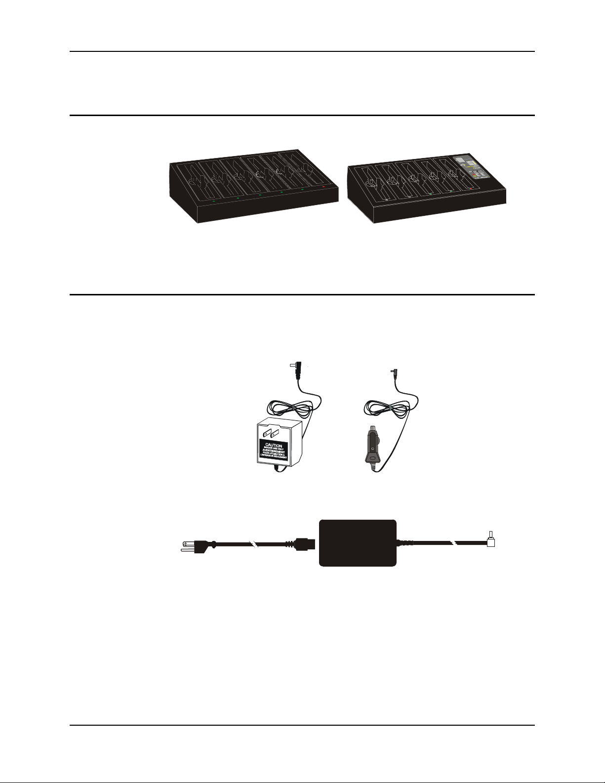
Figure 28 MX3 Multi-Charger and MX3 Multi-Charger Plus
The Main Battery can be charged in the LXE Multi-Charger. The Main Battery charges the
Backup Battery using the MX3-CE's internal charging circuitry.
External Power Supply (Optional)
The MX3-CE DC power jack is located on the endcap.
The cradle power jack is located on the back of the cradle.The MX3-CE (and the Desktop Cradle)
connect to any of the following power supplies through the DC Power Jack.
Figure 29 US AC/DC 12V Power Supply and Cigarette Lighter Adapter
Figure 30 International AC/DC 12V Power Supply
Note: When the MX3-CE is receiving power through a cradle connected to external power, the
cradle's Status LED and the MX3-CE's CHGR LED are illuminated.
E-EQ-MX3CEOGWW-F-ARC MX3-CE User’s Guide
Page 38
32 Cradles
Cradles
Note: The “MX3 Cradle Reference Guide” contains cradle installation and technical
information.
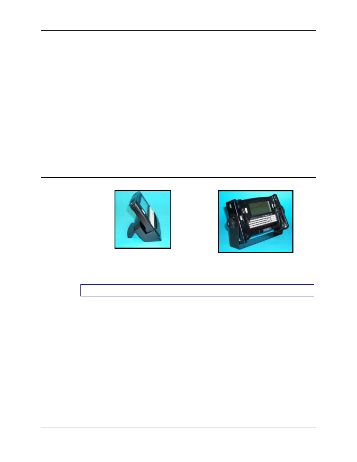
There are two types of cradles: a desktop cradle for table top charging/communication
applications and a vehicle mount cradle for vehicle mounted charging/communication
applications.
The cradles give the MX3-CE the ability to communicate with a host computer and other
equipment. In addition, using wall AC adapters or DC/DC converters, the cradle transfers power
to the internal charging circuitry of the MX3-CE and, in turn, the MX3-CE recharges the Main
Battery.
The MX3-CE can be either on or in Suspend mode while in the cradle. The MX3-CE can be
inserted and removed from the cradle with one hand.
Cables are available from LXE for connecting the cradle to a printer, a personal computer or a
barcode printer. Tethered scanners (for RS-232 cradle connection) are also available from LXE.
Desktop Cradle
Desktop Cradle Vehicle Mounted Cradle
Figure 31 MX3-CE in the Cradles
How To:
Lower the MX3-CE straight into the cradle, tilt it forwards and then let it rest backwards in the
cradle. Ensure that the MX3-CE is properly seated on the charging contacts. The CHGR LED will
illuminate green when the MX3-CE is correctly seated in the cradle. The CHGR LED will
illuminate red when the MX3-CE main battery is being charged (in a cradle connected to an
external power source).
To remove the MX3-CE, tilt the MX3-CE forward and lift it straight up out of the cradle.
Note: Do not "slam" or slide the MX3-CE sideways into the cradle. Damage may result.
MX3-CE User’s Guide E-EQ-MX3CEOGWW-F-ARC
Page 39
Cradles 33
Status LED
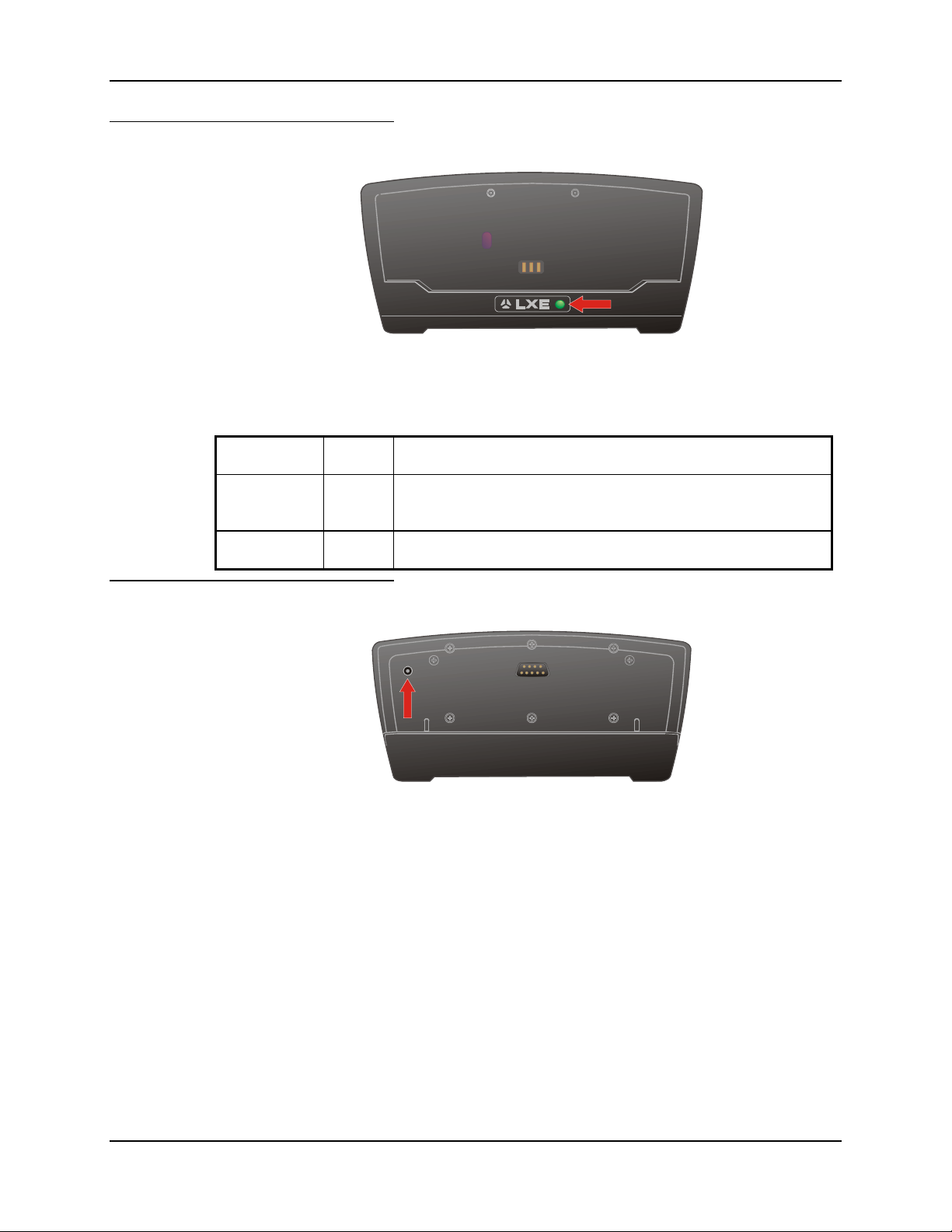
Figure 32 Desktop Cradle Status Indicator
An LED indicator shows the status of the cradle. When the indicator is not illuminated, there is no
power applied to the cradle.
Cradle Power Orange Power applied to the cradle.
Docked Green Power applied to the cradle and connection made with the MX3-
CE.
IR Active Red IR communication is active.
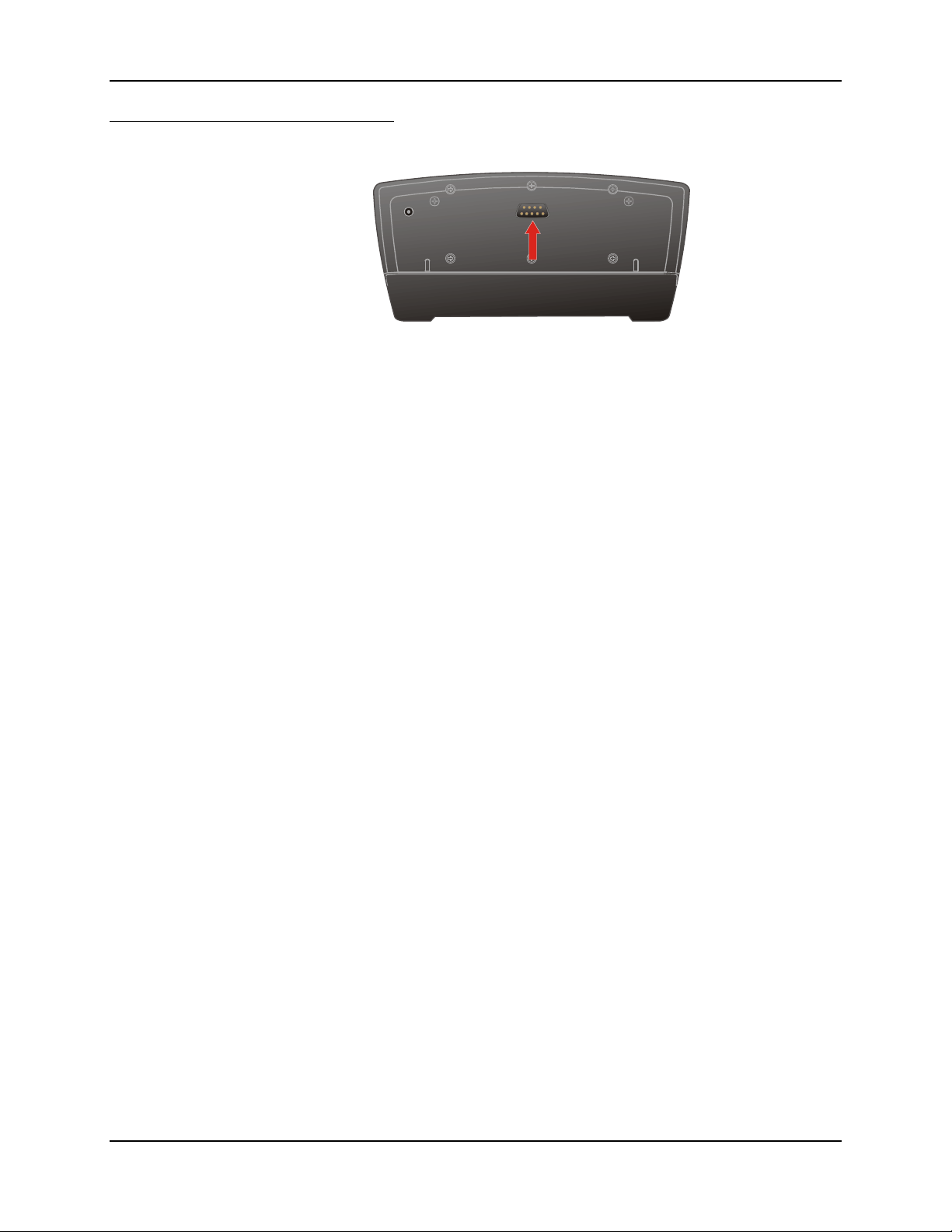
Power Connector
The Power connector is located on the back of the cradle. The cradle can be powered, if required,
by an LXE US AC Adapter or an LXE International AC Adapter. When powered, the cradle
transfers power to the internal charging circuitry of the MX3-CE allowing it to recharge the Main
Battery. A powered cradle supports RS-232 and IR communications.
Figure 33 Desktop Cradle Power Connector
E-EQ-MX3CEOGWW-F-ARC MX3-CE User’s Guide
Page 40
34 Cradles
RS-232 Connector
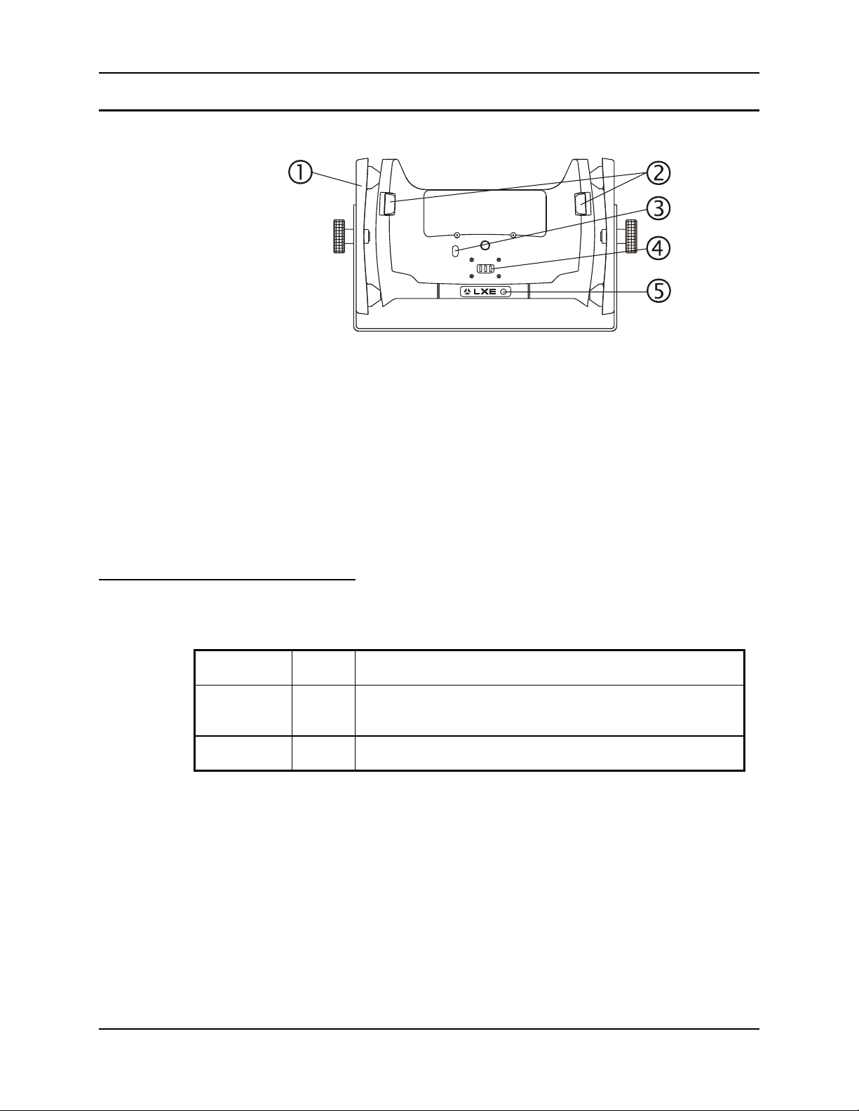
Figure 34 Desktop Cradle RS-232 Connector
The RS-232 connector is located on the back of the cradle. When the MX3-CE is properly
docked, the bi-directional half-duplex transceivers in the MX3-CE and cradle are aligned through
their IR windows. The half-duplex IR signals from the MX3-CE are converted to RS-232 signals
in the cradle and available at this connector.
Note: ActiveSync will not transfer files over the RS-232 connector on the cradle.
MX3-CE User’s Guide E-EQ-MX3CEOGWW-F-ARC
Page 41
Cradles 35
Vehicle Mount Cradle
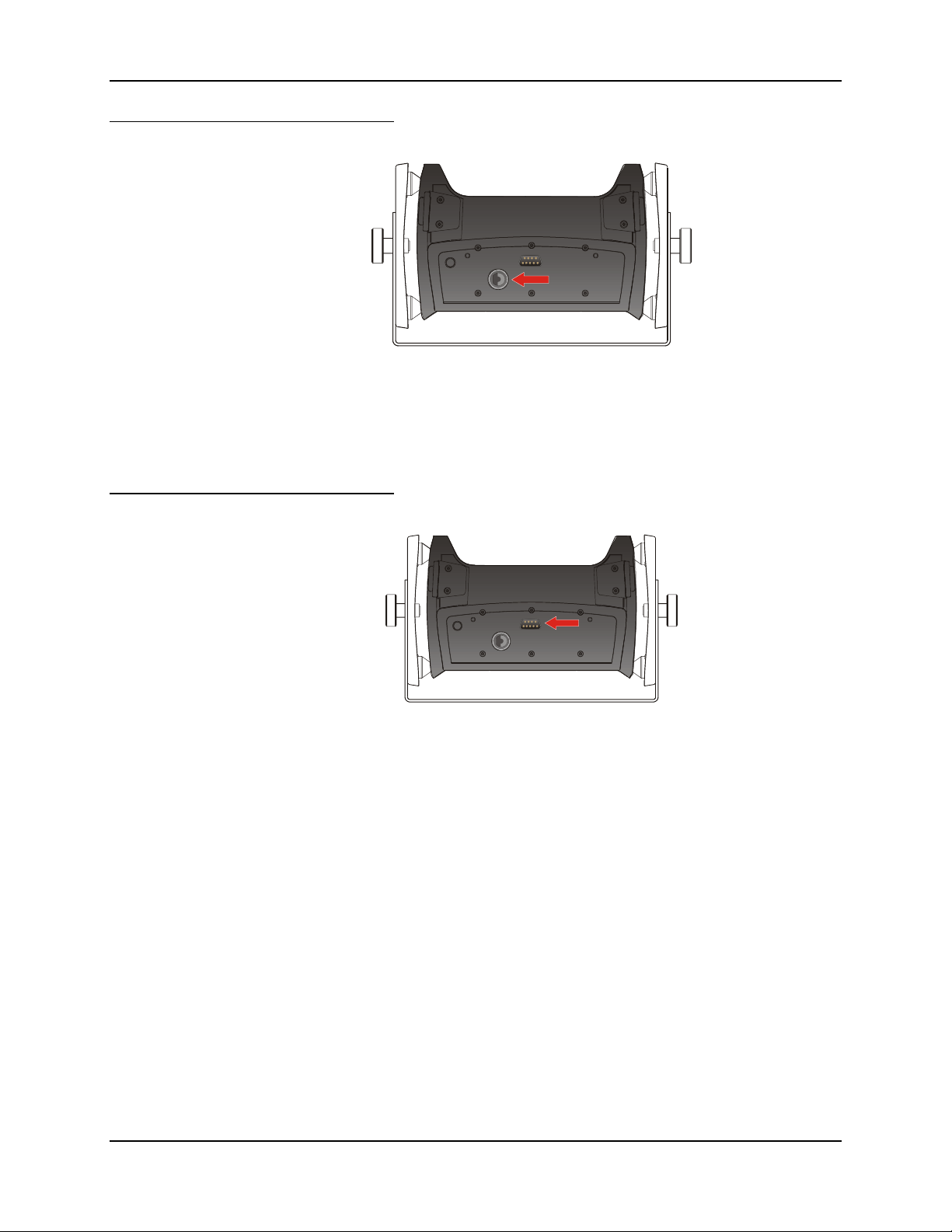
Figure 35 Vehicle Mount Cradle - Front
1 Vehicle Mount Bracket Assembly
2 MX3-CE Release Mechanism
3 IR Port
4 Battery Power Connection
5 Vehicle Cradle Status LED
Status LED
This cradle is specifically designed for vehicle mount applications. The cradle restrains the MX3CE and isolates the computer from shock and vibration. The MX3-CE is inserted into the cradle
by placing the base of the unit in the pocket and then firmly pressing the unit backwards until the
release mechanisms latch and hold the unit in the cradle. The MX3-CE is removed from the cradle
by pressing the release mechanisms and pulling the MX3-CE up and away from the cradle.
An LED indicator shows the status of the cradle. When the indicator is not illuminated, there is no
external power source connected to the cradle.
Cradle Power Orange Power applied to the cradle.
Docked Green Power applied to the cradle and connection made with the MX3-
CE.
IR Active Red IR communication active.
E-EQ-MX3CEOGWW-F-ARC MX3-CE User’s Guide
Page 42
36 Cradles
Power Connector
Figure 36 Vehicle Cradle Power Connector
The Power connector is located on the back of the cradle. The cradle is powered by either a
vehicle's 12V battery or from an approved accessory for vehicles with higher voltage (24 to 60
VDC) batteries. When powered, the cradle transfers external power to the MX3-CE, which in
turn, recharges the main battery. A powered cradle allows RS-232 and IR communication.
RS-232 Connector
Figure 37 Vehicle Cradle RS-232 Connector
The RS-232 connector is located on the back of the cradle. When the MX3-CE is properly
docked, the bi-directional half-duplex transceivers in the MX3-CE and cradle are aligned through
their IR windows. The half-duplex IR signals from the MX3-CE are converted to RS-232 signals
in the cradle and available at this connector.
Note: ActiveSync will not transfer files over the RS-232 connector on the cradle.
MX3-CE User’s Guide E-EQ-MX3CEOGWW-F-ARC
Page 43
Cradles 37
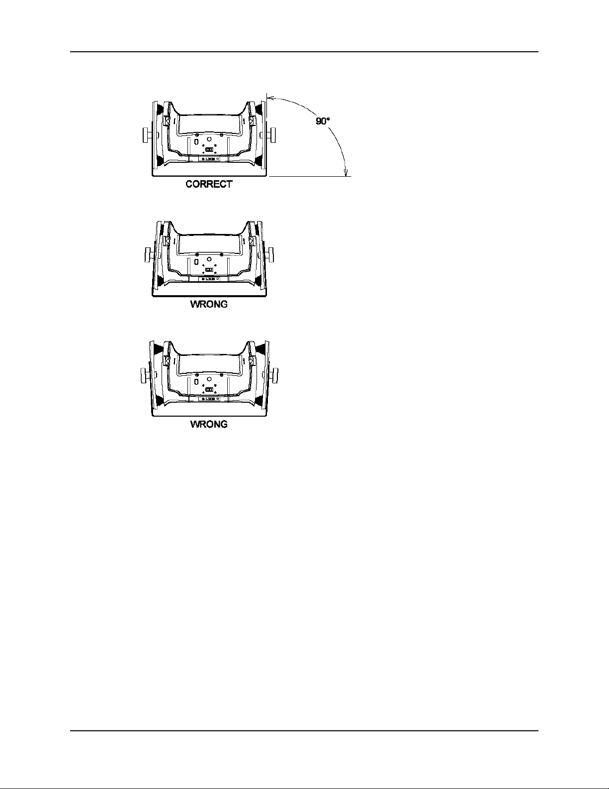
Care must be taken to avoid bending or
warping the bottom “U” shaped bracket
when attaching the cradle to a lift truck
or other vehicle.
A bent “U” bracket can over-compress
or over-extend the rubber isolators
leading to failure of the isolators.
E-EQ-MX3CEOGWW-F-ARC MX3-CE User’s Guide
Page 44

38 Cradles
MX3-CE User’s Guide E-EQ-MX3CEOGWW-F-ARC
Page 45
Appendix A Key Maps
Keypad
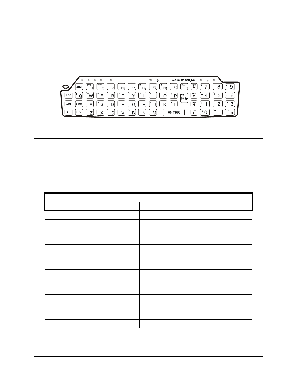
Figure 38 QWERTY Keypad
Key Map 101-Key Equivalencies
Note: This key mapping is used on hand held computers that are NOT running an LXE Terminal Emulator.
nd
When using a sequence of keys that includes the 2
key, press the 2nd key first then the rest of the key sequence.
Note: When the computer boots, the default condition of NumLock is On and the default condition of Caps (or
CapsLock) is Off. The Caps (or CapsLock) condition can be toggled with a 2
nd
+F1 key sequence. The
CAPS LED is illuminated when CapsLock is On.
To get this key
Contrast x F6
Volume x F8
Backlight x F10
2nd 2
Shift Shft
Alt Alt
Ctrl Ctrl
Scan4 Scan
Esc Esc
Space Spc
Enter Enter
CapsLock (Toggle) x F1
Back Space BkSp
Press These Keys and Then
nd
2
Shift Ctrl Alt CapsLock
Press this key
nd
Tab Tab
4
Left Scan key default value is Scan. Right Scan key default value is Enter.
E-EQ-MX3CEOGWW-F-ARC MX3-CE User’s Guide
Page 46

40 Key Maps
To get this key
BackTab x Tab
Break x F2
Pause x x F3
Up Arrow Up Arrow
Down Arrow Down Arrow
Right Arrow Right Arrow
Left Arrow Left Arrow
Insert x BkSp
Delete x DOT
Home x Left Arrow
End x Right Arrow
Page Up x Up Arrow
Page Down x Down Arrow
ScrollLock x x F4
F1 F1
Press These Keys and Then
nd
2
Shift Ctrl Alt CapsLock
Press this key
F2 F2
F3 F3
F4 F4
F5 F5
F6 F6
F7 F7
F8 F8
F9 F9
F10 F10
F11 x x F1
F12 x x F2
a Off A
b Off B
c Off C
d Off D
e Off E
f Off F
g Off G
h Off H
i Off I
MX3-CE User’s Guide E-EQ-MX3CEOGWW-F-ARC
Page 47

Key Maps 41
To get this key
j Off J
k Off K
l Off L
m Off M
n Off N
o Off O
p Off P
q Off Q
r Off R
s Off S
t Off T
u Off U
v Off V
w Off W
x Off X
Press These Keys and Then
nd
2
Shift Ctrl Alt CapsLock
Press this key
y Off Y
z Off Z
A x A
B x B
C x C
D x D
E x E
F x F
G x G
H x H
I x I
J x J
K x K
L x L
M x M
N x N
O x O
P x P
Q x Q
R x R
E-EQ-MX3CEOGWW-F-ARC MX3-CE User’s Guide
Page 48

42 Key Maps
To get this key
S x S
T x T
U x U
V x V
W x W
X x X
Y x Y
Z x Z
1 1
2 2
3 3
4 4
5 5
6 6
7 7
Press These Keys and Then
nd
2
Shift Ctrl Alt CapsLock
Press this key
8 8
9 9
0 0
DOT DOT
< x 0
[ x 1
] x 2
> x 3
= x 4
{ x 5
} x 6
/ x 7
- x 8
+ x 9
* x I
: (colon) x D
; (semicolon) x F
? x L
` x N
_ (underscore) x M
MX3-CE User’s Guide E-EQ-MX3CEOGWW-F-ARC
Page 49
Key Maps 43
To get this key
, (comma) x J
‘ (apostrophe) x H
~ (tilde) x B
\ x S
| x A
“ x G
! x Q
@ x W
# x E
$ x R
% x T
^ x Y
& x U
( x O
) x P
Press These Keys and Then
nd
2
Shift Ctrl Alt CapsLock
Press this key
E-EQ-MX3CEOGWW-F-ARC MX3-CE User’s Guide
Page 50

44 Key Maps
MX3-CE User’s Guide E-EQ-MX3CEOGWW-F-ARC
Page 51
Appendix B Regulatory Notices and Safety Information
FCC Information:
This device complies with FCC Rules, part 15. Operation is subject to the following conditions:
1. This device may not cause harmful interference
and
2. This device must accept any interference that may be received, including interference that may cause
undesired operation.
Note: This equipment has been tested and found to comply with the limits for a Class A digital device, pursuant to
part 15 of the FCC rules. These limits are designed to provide reasonable protection against harmful interference
when the equipment is operated in a commercial environment. This equipment generates, uses, and can radiate radio
frequency energy and, if not installed and used in accordance with the instruction manual, may cause harmful
interference to radio communications. Operation of this equipment in a residential area is likely to cause harmful
interference in which case the user will be required to correct the interference at his own expense.
Warning: Changes or modifications to this device not expressly approved by LXE, Inc., could void the user’s
authority to operate this equipment.
EMC Directive Requirements:
This is a Class A product. In a domestic environment this product may cause radio interference in which case the
user may be required to take adequate measures.
Industry Canada:
This Class A digital apparatus meets all requirements of the Canadian Interference Causing Equipment Regulations.
Operation is subject to the following two conditions: (1) this device may not cause harmful interference, and (2) this
device must accept any interference received, including interference that may cause undesired operation.
Cet appareil numérique de la classe A respecte toutes les exigences du Règlement sur le matériel brouiller du
Canada. Le present appareil numérique n’emet pas de bruits radioélectriques dépassant les limites applicables aux
appareils numeriques de le Classe A préscrites dans le Reglement sur le brouillage radioélectrique édits par le
ministere des Communications du Canada.
RF Safety Notice
Caution
Notice:
The long term characteristics or the possible physiological effects of radio frequency electromagnetic fields have
not been investigated by UL.
Li-Ion Battery
When disposing of the MX3-CE Main Battery, the following precautions should be observed: The battery should
be disposed of promptly. The battery should not be disassembled or crushed. The battery should not be heated
above 212°F (100°C) or incinerated.
This device is intended to transmit RF energy. In accordance with FCC and Industry Canada
radio-frequency safety regulations, when operating this device with the Hip-Flip accessory, it
should be used in accordance with the user's instructions. Additionally, the user should take care
to ensure that a minimum separation distance of 15cm (6 in.) is maintained from the antenna to
nearby persons. Use of this device in a manner not consistent with these instructions can increase
the risk of RF exposure. This device is not to be co-located with other transmitters.
E-EQ-MX3CEOGWW-F-ARC MX3-CE User’s Guide
Page 52
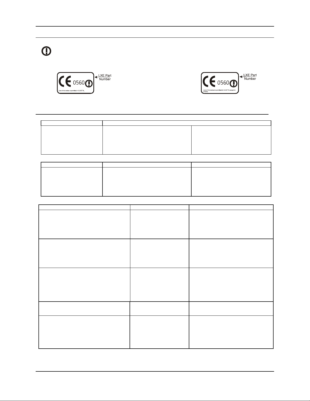
46 Regulatory Notices and Safety Information
R&TTE Directive Requirements (Applies only to equipment operated within the EU/EFTA)
Information to User
A label on the exterior of the device should resemble one of the labels shown below (the label contains the LXE part number of
the installed radio card). The labels shown below and affixed to the device, identify where the device may be used and where its
use is restricted. Use of a device is prohibited in countries not listed below or otherwise identified by the label. (May or may not
include the 0560 Notifed Body No.)
Permitted for use in: Austria, Belgium, Denmark, Finland, Germany, Greece, Hungary,
Iceland, Italy, Ireland, Liechtenstein, Luxembourg, Netherlands, Norway, Portugal, Spain,
Sweden, Switzerland, and the United Kingdom
Permitted for use in France.
MX3-CE Computer Approvals:
Product EMI / EMC Standards Safety Standards
MX3-CE
FCC Part 15 Subpart B, Class A
EN 55022:1998, (CISPR 22:1997)
Class A
EN 55024:1998
Industry Canada Class A
UL 1950; CSA C22.2 No. 950
CDRH: 21 CFR 1040.10 and 1040.11
EN 60950
IEC 60825-1
IEC 950
Cradle Approvals:
Product EMI / EMC Standards Safety Standards
MX3-CE Table
MX3-CE Vehicle Mount
FCC Part 15 Subpart B, Class A
EN 55022:1998, (CISPR 22:1997)
Class A
EN 55024:1998
Industry Canada Class A
UL 1950; CSA C22.2 No. 950
EN 60950
IEC 950
Transceiver:
Transceiver RF Standards Notes
480824-3300 (LXE Part No.)
LXE 6400 System 2.4GHz Type II PCMCIA Card
480628-4096 (LXE Part No.)
LXE 6500 System 2.4GHz Type II PCMCIA Card
6726 (LXE Model No.)
4810P3S01 (LXE Part No.)
LXE 6200 System 900MHz Type III PCMCIA Card
6816 (LXE Model No.)
2.4GHz Type II PCMCIA Card
FCC Part 15, Subpart C
FCC Part 2
ETS 300 328
ETS 300 826
IC-RSS 210
IC-RSS 102
FCC Part 15, Subpart C
FCC Part 2
ETS 300 328
ETS 300 826
IC-RSS 139
IC-RSS 102
FCC Part 15, Subpart C
FCC Part 2
EN 300 328
EN 300 826
IC-RSS 139
IC-RSS 102
FCC Part 15, Subpart C
IC-RSS 210
FCC Part 15, Subpart C
FCC Part 2
EN 300 328
EN 300 826
IC-RSS 139
IC-RSS 102
Unlicensed Operation
Unlicensed Operation
Requires License for Outdoor Use
Unlicensed Operation
Unlicensed Operation
Requires License for Outdoor Use
Unlicensed Operation
Unlicensed Operation
Requires License for Outdoor Use
Unlicensed Operation
Unlicensed Operation
Unlicensed Operation
Unlicensed Operation
Requires License for Outdoor Use
MX3-CE User’s Guide E-EQ-MX3CEOGWW-F-ARC
Page 53
Regulatory Notices and Safety Information 47
LXE Transceiver 480628-4096 Declaration of Conformity
DECLARATION OF CONFORMITY
1999/5/EC
93/68/EEC
Type of Equipment: Direct Sequence 2.4 GHz Wireless LAN Card
Brand Name or Trademark: LXE
Type Designation: 480628-4096
Manufacturer: LXE Inc.
Address: 125 Technology Parkway
Year of Manufacturer: 2000
The following harmonized European Standards, technical specifications, or other normative
documents have been applied:
EMI / EMC Standards:
EN 55022 : 1995 Limits and methods of measurement of radio disturbance characteristics
ETS 300 826 : 1997 Electromagnetic compatibility - Generic immunity standard, Part 1:
EN 61000-4-2 : 1995 Electrostatic discharge immunity test
EN 61000-4-3 : 1997 Radiated radio frequency electromagnetic field immunity test
EN 61000-4-6 : 1996 RF conducted immunity test
Radio Frequency Standards:
ETS 300 328 : 1996 Radio Equipment and Systems (RES);
Safety Standards:
IEC 950-2: 1991
+ Amendments
A1..A4
We, LXE Inc., declare that the equipment specified above complies with all Essential Health
Place: LXE Inc., Norcross GA USA
Date of issue: 1 March, 2000 R. Sam Wismer,
according to Directives:
Radio Equipment and Telecommunications Terminal Equipment and
the mutual recognition of their conformity
CE Marking Directive
Norcross, GA 30092-2993 USA
of information technology equipment
Residential, commercial and light industrial
Wideband transmission systems;
Technical characteristics and test conditions for data transmission
equipment operating in the 2,4 GHz ISM band and using spread spectrum
modulation techniques
Safety of information technology equipment, including electrical business
equipment
and Safety Requirements of the above Directives and Standards, as amended.
Signed:
Lead Approvals Engineer
LXE Inc. 125 Technology Parkway Norcross, GA 30092-2993 USA
ph. 770/447-4224 fax 770/447-6928
E-EQ-MX3CEOGWW-F-ARC MX3-CE User’s Guide
Page 54
48 Regulatory Notices and Safety Information
LXE Transceiver 480824-3300 Declaration of Conformity
DECLARATION OF CONFORMITY
1999/5/EC
93/68/EEC
Type of Equipment: Frequency Hopping 2.4 GHz Wireless LAN Card
Brand Name or Trademark: LXE
Type Designation: 480824-3300
Manufacturer: LXE Inc.
Address: 125 Technology Parkway
Year of Manufacturer: 2000
The following harmonized European Standards, technical specifications, or other normative
documents have been applied:
EMI / EMC Standards:
EN 55022 : 1995 Limits and methods of measurement of radio disturbance characteristics
ETS 300 826 : 1997 Electromagnetic compatibility - Generic immunity standard, Part 1:
EN 61000-4-2 : 1995 Electrostatic discharge immunity test
EN 61000-4-3 : 1997 Radiated radio frequency electromagnetic field immunity test
EN 61000-4-6 : 1996 RF conducted immunity test
Radio Frequency Standards:
ETS 300 328 : 1996 Radio Equipment and Systems (RES);
Safety Standards:
IEC 950-2: 1991
+ Amendments
A1..A4
We, LXE Inc., declare that the equipment specified above complies with all Essential Health
Place: LXE Inc., Norcross GA USA
R. Sam Wismer,
according to Directives:
Radio Equipment and Telecommunications Terminal Equipment and
the mutual recognition of their conformity
CE Marking Directive
Norcross, GA 30092-2993 USA
of information technology equipment
Residential, commercial and light industrial
Wideband transmission systems;
Technical characteristics and test conditions for data transmission
equipment operating in the 2,4 GHz ISM band and using spread spectrum
modulation techniques
Safety of information technology equipment, including electrical business
equipment
and Safety Requirements of the above Directives and Standards, as amended.
Signed:
Lead Approvals Engineer
LXE Inc. 125 Technology Parkway Norcross, GA 30092-2993 USA
ph. 770/447-4224 fax 770/447-6928
MX3-CE User’s Guide E-EQ-MX3CEOGWW-F-ARC
Page 55
Regulatory Notices and Safety Information 49
LXE Transceiver LXE 6726 Declaration of Conformity
DECLARATION OF CONFORMITY
according to Directives:
1999/5/EC Radio Equipment and Telecommunications Terminal Equipment
93/68/EEC
Type of Equipment: Direct Sequence 2.4 GHz Wireless LAN Card
Brand Name or Trademark: LXE
Type Designation: LXE 6726
Manufacturer: LXE Inc.
Address: 125 Technology Parkway
Year of Manufacturer: 2001
The following harmonized European Standards, technical specifications, or other normative
documents have been applied:
EMC:
EN 301 489-1: 07-2000
EN 301 489-17 07-2000
Radio:
EN 300 328-1 and -2: 2000-7 Radio Equipment and Systems (RES);
Safety:
EN 60950-2: 1992 + A1..A4 Safety of information technology equipment, including electrical
We, LXE Inc., declare that the equipment specified above complies with all Essential Health and
Safety Requirements of the above Directives and Standards, as amended.
and the mutual recognition of their conformity
CE Marking Directive
Norcross, GA 30092-2993 USA
Electromagnetic compatibility and Radio spectrum Matters
(ERM); ElectroMagnetic Compatibility (EMC) standard for radio
equipment and services; Part 1: Common technical
requirements
Electromagnetic compatibility and Radio spectrum Matters
(ERM); ElectroMagnetic Compatibility (EMC) standard for radio
equipment and services; Part 17: Specific conditions for
Wideband data and HIPERLAN equipment
Wideband transmission systems;
Technical characteristics and test conditions for data
transmission equipment operating in the 2,4 GHz ISM band
and using spread spectrum modulation techniques
business equipment
Place LXE Inc., Norcross GA USA
Date of issue 24 June 2004
C. Binnom Jr.
RF Approvals Engineer
LXE Inc. 125 Technology Parkway Norcross, GA 30092-2993 USA
ph. 770/447-4224 fax 770/447-6928
E-EQ-MX3CEOGWW-F-ARC MX3-CE User’s Guide
Page 56

50 Regulatory Notices and Safety Information
Annex to DoC for LXE 6726
With regard to the use of external antennas
The LXE 6726 can be equipped with external antennas. The antennas listed have been evaluated with the LXE 6726 pursuant to
ETSI EN 300 328, and therefore meet the definition of ‘dedicated antenna’ per ERC/REC 70-03 Appendix 1 Table 3; thus the
requirement set forth in ERC/REC 70-03 , Annex 3 are met by the LXE model 6726 transceiver.
Dedicated Antennas for use with LXE 6726
LXE P/N
153180-0001 0 dBi 17 dBm Omni, for LXE VX-series computers
155522-0001 0 dBi 17 dBm Omni, for LXE MX1-series computers
155814-0001 0 dBi 17 dBm Patch, for LXE MX1-series computers
157368-0001 0 dBi 17 dBm Patch, for LXE MX3-series computers
157399-0001 0 dBi 17 dBm Omni, for LXE MX5-series computers
99004-0027 0 dBi 17 dBm 3 dB Omni, for LXE model 2325 computer
DAC2450CT1
(Toko P/N)
153179-0001 0 dBi 17 dBm Omni, Access Point Antenna
153325-0001 0 dBi 17 dBm Omni, Access Point Antenna
480424-0400 0 dBi 17 dBm Omni, Access Point Antenna
153599-0001 3 dBi 17 dBm Omni, Access Point Antenna
153600-0001 3 dBi 17 dBm Omni, Access Point Antenna
480424-3404 3 dBi 17 dBm Omni, Access Point Antenna
155846-0001 3 dBi 17 dBm Spire® Access Point Antenna
155845-0001 6 dBi 13 dBm Spire® Access Point Antenna
155311-0001 6 dBi 13 dBm Patch, Access Point Antenna
480424-3411 6 dBi 13 dBm Patch, Access Point Antenna
480424-3402 6 dBi 13 dBm Patch, Access Point Antenna
481246-2400 6 dBi 13 dBm Patch, Access Point Antenna
480424-1702 6 dBi 13 dBm
480424-0411 9 dBi 7 dBm Omni, Access Point Antenna
480429-2703 12 dBi 7 dBm
480429-0411 12 dBi 7 dBm Omni, Access Point Antenna
460601-3020 15 dBi 3 dBm YAGI, Access Point Antenna
460602-3020 15 dBi 3 dBm YAGI, Access Point Antenna
480429-0415 15 dBi 3 dBm Omni, Access Point Antenna
Antenna Gain Radio Power Level Antenna Description
2.15 dBi 17 dBm Omni, for LXE MX2-series computers
180° Directional, Access Point Antenna
90° Directional, Access Point Antenna
C. Binnom Jr.
RF Approvals Engineer
24 June 2004
LXE Inc. 125 Technology Parkway Norcross, GA 30092-2993 USA
ph. 770/447-4224 fax 770/447-6928
MX3-CE User’s Guide E-EQ-MX3CEOGWW-F-ARC
Page 57
Regulatory Notices and Safety Information 51
LXE Transceiver LXE 6816 Declaration of Conformity
DECLARATION OF CONFORMITY
according to:
the R&TTE Directive; 99/5/EEC
The EMC Directive; 89/336/EEC
The Low Voltage Directive; 73/23/EEC
and the Marking Directive; 93/68/EEC
Type of Equipment: DSSS 2.4GHz WLAN Radio Card
Brand Name or Trademark: LXE
Type Designation: 6816
Manufacturer: LXE Inc.
Address: 125 Technology Parkway
The following harmonized European Norms have been applied:
EMC Standards:
EN 301 489-1: 07-2000 Electromagnetic compatibility and Radio spectrum Matters (ERM);
EN 301 489-17:07-2000 Electromagnetic compatibility and Radio spectrum Matters (ERM);
EN 55022: 1998 Limits and methods of measurement of radio disturbance
Radio Standards:
EN 300 328-1 and -2: 2000-7
Safety Standard:
EN60950-1: 2001
The product carries the CE Mark:
ElectroMagnetic Compatibility (EMC) standard for radio
equipment and services; Part 1: Common technical requirements
ElectroMagnetic Compatibility (EMC) standard for radio
equipment and services; Part 17: Specific conditions for
Wideband data and HIPERLAN equipment
characteristics of information technology equipment
Radio Equipment and Systems (RES);
Wideband transmission systems;
Technical characteristics and test conditions for data transmission
equipment operating in the 2.4 GHz ISM band and using spread
spectrum modulation techniques
Safety of information technology equipment, including electrical
business equipment
Norcross, GA 30092 USA
We, LXE Inc., declare that the equipment specified above complies with all Essential Health
and Safety Requirements of the above Directives and Standards, as amended.
Date of issue: June 18, 2003
Cyril A. Binnom Jr.
Regulatory Engineer
LXE Inc. 125 Technology Parkway Norcross, GA 30092-2993 USA
ph. 770/447-4224 fax 770/447-6928
E-EQ-MX3CEOGWW-F-ARC MX3-CE User’s Guide
Page 58
52 Regulatory Notices and Safety Information
Annex to DoC for LXE 6816
With regard to the use of external antennas
The LXE 6816 can be equipped with external antennas. The antennas listed have been assessed with the LXE 6816 pursuant to EN
300 328, and therefore meet the definition of ‘dedicated antenna’. The table below lists the maximum output power setting for the
radio module in order to result in a total EIRP of 100mW or less. Any combination of output power and a specific type of antenna
resulting in an EIRP greater than 100mW is illegal for use throughout the Community and is outside the scope of this DoC. Antennas
not listed below are also outside the scope of this DoC.
Dedicated Antennas for use with LXE 6816
LXE Antenna
Part Number
153180-0001 N/A 2.2 dBi 17 dBm Cushcraft Omni Antenna
155846-0001 6000A279ANT3SPIREL
155845-0001 6000A277ANT6SPIREL
480424-0411 N/A 9 dBi 11 dbm Mobile Mark Omni Antenna
155104-0001 N/A 0 dbi 20 dbm LXE Omni
154591-0001 N/A 0 dbi 20 dbm LXE Patch
Toko DAC2450CT1 N/A 0 dbi 20 dbm LXE Omni
157368-0001 N/A 0 dbi 20 dbm LXE Omni
158586-0001 N/A 0 dbi 20 dbm LXE Omni
158399-0001 N/A 0 dbi 20 dbm LXE Omni
Cyril A. Binnom Jr.
Regulatory Engineer
18 June 2003
LXE Model
Number
6000A280ANT3SPIRER
6000A283ANT3INDSPR
6000A278ANT6SPIRER
6000A282ANT3INDSPR
Antenna
Gain
3 dBi 17 dBm Spire® Omni Antenna
6 dBi 13 dBm Spire® Omni Antenna
Max Radio
Power Level
Antenna
Description
LXE Inc. 125 Technology Parkway Norcross, GA 30092-2993 USA
ph. 770/447-4224 fax 770/447-6928
MX3-CE User’s Guide E-EQ-MX3CEOGWW-F-ARC
Page 59
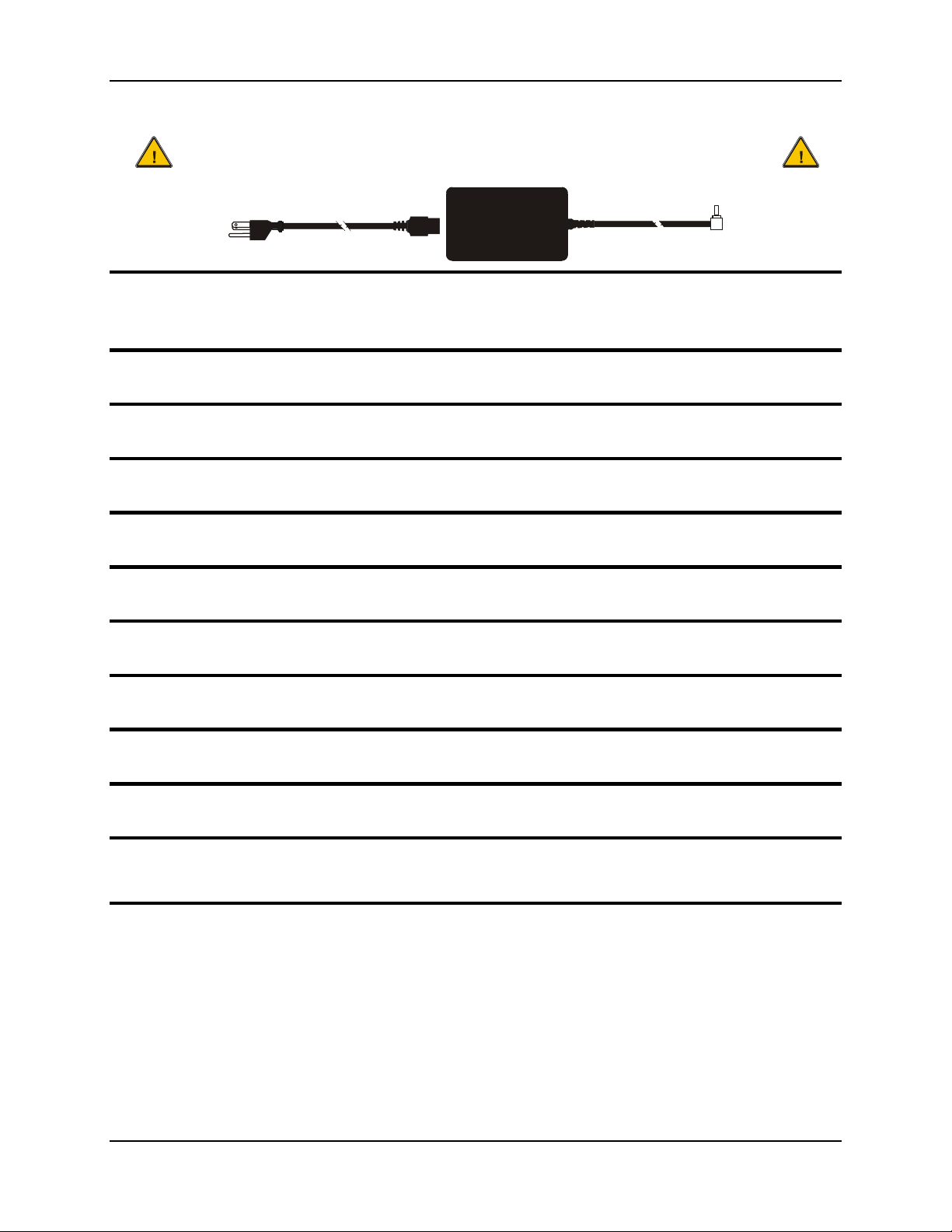
Regulatory Notices and Safety Information 53
A/C Power Supply Safety Statement – MX3
Output Rated 12 VDC, 1 A.
Optional A/C Power Supply:
Outside North America, this unit is intended for use with an IEC certified ITE power supply with output rated as
stated at the top of this page. (US)
Alimentation c.a. optionnelle:
Hors de l'Amérique du Nord, cette unité est conçue pour être utilisée avec une alimentation ITE certifiée CEI de sortie nominale
indiquée au haut de cette page. (FR)
Valgfrit vekselstrømforsygning
Udenfor Nord Amerika er denne enhed udstattet med en IEC (international elektronisk Kommission) udfærdiget med en ITE
strømforsygning med strømudgang som fastslået på denne sides begyndelse. (DK)
Vaihtoehtoinen vaihtovirran syöttölaite:
Pohjois-Amerikan ulkopuolella tämä laite on tarkoitettu käytettäväksi sellaisen IEC:n sertifioiman ITE-tehonsyöttölaitteen
kanssa, jonka antoteho on tämän sivun yläosassa esitetyn mukainen. (FI)
Optionales Netzteil (Wechselstrom)
Außerhalb Nordamerikas sollte diese Einheit über ein der IEC-Norm entsprechendes ITE-Netzteil gespeist werden, und zwar mit
einer wie oben auf dieser Seite genannten Ausspeisung. (DE)
Προαιρετική Τροφοδοσία Συνεχούς Ρεύματος
Εκτός Β. Αμερικής, η μονάδα αυτή προορίζεται για χρήση με ένα τροφοδοτικό ITE πιστοποιημένο κατά IEC με ονομαστική
ισχύ όπως δηλώνεται στην αρχή της σελίδας. (GR)
Alimentazione opzionale a corrente alternata:
Al di fuori dei paesi dell'America del nord, l'unità deve essere impiegata con un dispositivo d'alimentazione per attrezzature
informatiche approvato dalla IEC la cui potenza nominale sia pari a quella indicata all'inizio della pagina. (IT)
Vekselstrømforsyning (ekstrautstyr):
Utenfor Nord-Amerika skal dette produktet brukes med en IEC-sertifisert ITE-strømforsyning med klassifisert effekt som angitt
øverst på denne siden. (NO)
Fornecimento opcional de CA:
Fora dos EUA, esta unidade destina-se a ser usada com dispositivos de fornecimento de corrente ITE com certificação IEC, com
a capacidade indicada no topo desta página. (PT)
Suministro optativo de corriente alterna
Fuera de América del Norte, esta unidad se debe utilizar con un alimentador ITE homologado por la IEC (comisión
electrotécnica internacional) con una salida que tenga la calificación que figura en la parte superior de esta página. (ES)
Valfri A/C Strömförsörjning
Utanför Nordamerika är det meningen att denna enheten används med en IEC-certifierad ITE-strömförsörjare med den uteffekt
som anges längst uppe på den här sidan. (SE)
İsteğe Bağlı A/C Güç Kaynağı:
Kuzey Amerika dışında, bu ünite, çıkış sınıflandırması bu sayfanın başında belirtilen IEC sertifikalı bir ITE güç kaynağı ile
birlikte kullanılmak üzere tasarlanmıştır. (TR)
Updated 10/01/2001
Legend: Danish – DK; English – US; Finnish – FI; French- - FR; German – DE; Greek – GR; Italian – IT;
Norwegian – NO; Portuguese – PT; Spanish – ES; Swedish – SE; Turkish – TR.
E-EQ-MX3CEOGWW-F-ARC MX3-CE User’s Guide
Page 60

54 Regulatory Notices and Safety Information
Warning:
This product uses laser light. One of the following labels is provided on the scanner. Please read the Caution
statement. (US)
Mise én garde:
Ce produit utilise un rayon laser. L’une des étiquettes suivantes est apposée sur le scanneur. Veuillez lire
l’avertissement qu’elle contient. (FR)
Advertência:
Este produto usa luz de laser. O scanner contém um dos seguintes avisos. Favor ler o Aviso. (PT)
Varning:
Denna produkt använder laserljus. En av de nedanstående etiketterna sitter på scannern. Var god läs varningstexten.
(SE)
Advarsel:
Dette produkt anvender laserlys. En af følgende mærkater anvendes på scanneren. Læs venligst
sikkerhedsforanstaltningen. (DK)
Varoitus:
Tämä tuote käyttää laservaloa. Skannerissa on jokin seuraavista tarroista. Lue Huomio-kohta. (FI)
Warnung:
Dieses Produkt verwendet Laserlicht. Eines der folgenden Etiketten befindet sich auf dem Scanner. Bitte lesen Sie
den Gefahrenhinweis. (DE)
Attenzione:
Questo prodotto utilizza luce laser. Una delle etichette seguenti c’ ubicata sullo scanner. Si raccomanda di leggere
con attenzione le avvertenze riportate. (IT)
Advarsel:
Dette utstyret bruker laserlys. En av følgende etiketter er plassert på scanneren. Les advarselen på etiketten. (NO)
Advertencia:
Este producto usa luz de láser. Las etiquetas se proveen en la máquina exploradora. Por favor, lea detenidamente la
explicación para las precauciones. (ES)
Waarschuwing:
Dit product gebruikt laserlicht. Een van de volgende labels is op de scanner aangebracht. Lees a.u.b. de
waarschuwing onder Oppassen. (NL)
Laser Light Safety Statement
MX3-CE User’s Guide E-EQ-MX3CEOGWW-F-ARC
Page 61
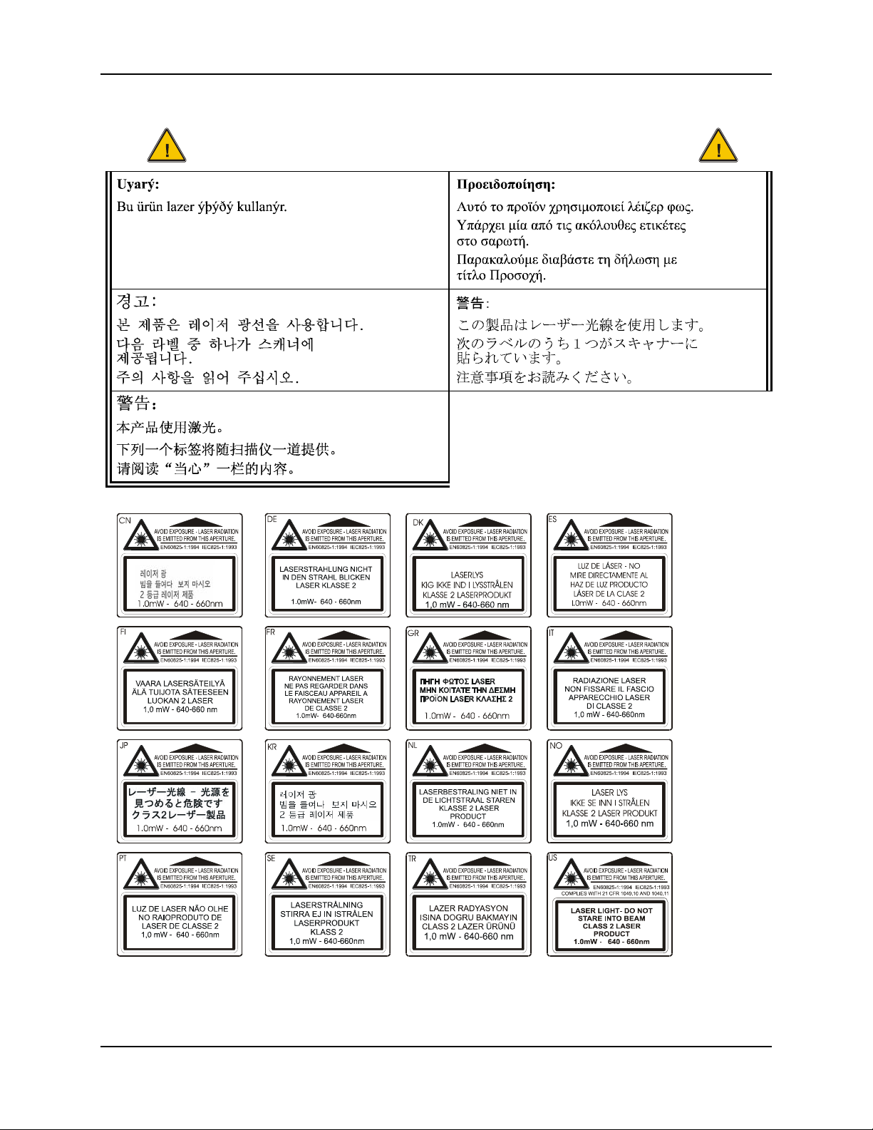
Regulatory Notices and Safety Information 55
i
ikk
.
Aþaðýdaki etiketlerden bir tanes
tarayýcýnýn üstünde saðlanýr.
Lütfen D
at ifadesini okuyun
Laser Light Safety Statement
(TR)
(KR)
Legend:
Chinese-CN; Danish-DK; Dutch-NL; English-US; Finnish-
(CN)
Labels - MX3-CE Hand Held Computer
FI; French-FR; German-DE; Greek-GR; Italian-IT;
Japanese-JP; Korean-KR; Norwegian-NO; Portuguese-PT;
Spanish-ES; Swedish-SE; Turkish-TR
(GR)
(JP)
E-EQ-MX3CEOGWW-F-ARC MX3-CE User’s Guide
Page 62

56 Regulatory Notices and Safety Information
MX3-CE User’s Guide E-EQ-MX3CEOGWW-F-ARC
Page 63

Index
2nd key function ...................................................26
A
AC Power
and LEDs on cradles ...........................................31
Alt key function ....................................................27
Audio ....................................................................15
Audio jack ..............................................................9
B
Backlight for Display............................................21
Backlight Timer....................................................12
Battery
charge before using...............................................7
Hot Swap.............................................................30
Battery Chargers .............................................18, 31
Battery Compartment..............................................7
Battery, Backup
described .............................................................30
Battery, Main ........................................................29
described .............................................................29
Baud Rate
IR port.................................................................25
Blanking Timer.....................................................13
Bootup ....................................................................8
Display
adjust contrast .....................................................12
Features...............................................................21
Pixels...................................................................21
Display Cleaning ..................................................22
Display Contrast ...................................................12
E
Endcaps and COM Ports.......................................24
Enter key function ................................................26
Entering Data........................................................16
Environmental Specifications.................................2
External power supplies..........................................9
F
Features...................................................................1
Function
2nd Key...............................................................26
Alt Key................................................................27
Caps Mode ..........................................................27
Ctrl Key...............................................................26
Enter Key ............................................................26
Scan Key .............................................................26
Shft Key ..............................................................27
Spc Key...............................................................27
C
Calibrate touch screen...........................................22
Caps mode function ..............................................27
Charger, battery ..............................................18, 31
Cleaning................................................................22
Color displays .................................................12, 21
COM 2, IR port.....................................................25
COM ports ............................................................24
Components
Back ......................................................................6
Front......................................................................5
Top........................................................................6
Cradles, function...................................................32
Ctrl key function...................................................26
D
Data entry .............................................................16
Desktop cradle ......................................................32
Power connection................................................33
RS-232 connection..............................................34
Status Indicator ...................................................33
G
Getting Started........................................................4
H
Handstrap..............................................................10
Hot Swap Battery..................................................30
I
IEC IP56 .................................................................2
Infrared (IR) port, described.................................25
Infrared Data Access (IrDA) ................................25
IR operating envelope...........................................25
IR Port
bi-directional half-duplex....................................25
K
Keymaps ...............................................................39
Keypad and entering data .....................................16
Keypad Shortcuts..................................................11
E-EQ-MX3CEOGWW-F-ARC MX3-CE User’s Guide
Page 64

58 Index
L
LEDs
2nd function ........................................................28
ALT function ......................................................28
BATT B function ................................................28
BATT M function ...............................................28
CAPS function ....................................................28
CHGR function ...................................................28
CTRL function....................................................28
on keypads,location.............................................28
SCNR function....................................................28
SHFT function ....................................................28
STAT function ....................................................28
Li-Ion battery life....................................................1
Lithium-Ion (Li-ion) .............................................29
Location, Components........................................5, 6
M
Main Battery
components .........................................................29
Manuals ................................................................19
Mode Key Functions ............................................27
O
Operating Temperature...........................................2
P
Pen Stylus .......................................................11, 21
Pen Stylus and data entry......................................16
Port, Infrared.........................................................25
Power button...........................................................8
Power Off Timer...................................................14
Power Supply, Cigarette Lighter Adapter.............31
Power Supply, International AC/DC ....................31
Power Supply, US AC/DC ...................................31
Programmable Buttons .........................................23
Q
Quick Start Instructions ..........................................4
QWERTY keypad.................................................26
R
Reboot.....................................................................8
Recalibrate ............................................................22
Regulatory Notices ...............................................45
S
Safety Information................................................45
Save settings to non-volatile memory...................14
Scan key function .................................................26
Scanner LED, functioning ....................................17
Scanning and data entry........................................17
Screwdriver
Phillips, for handstrap .........................................10
Shift key function .................................................27
Space key function................................................27
Specifications
Environmental.......................................................2
Stylus ..............................................................11, 21
Stylus and data entry.............................................16
Stylus Clip ..............................................................8
Switching
COM ports ..........................................................24
T
Tethered scanners .................................................25
Touch Screen ..................................................11, 21
Keypad Shortcuts................................................11
Touch Screen and data entry.................................16
Transflective Display............................................21
Transmissive Display............................................21
U
USB port...............................................................25
V
Vehicle cradle
RS-232 connection..............................................36
Status Indicator ...................................................35
Vehicle mount cradle
Components ........................................................35
Power connection................................................36
View
Display ................................................................21
Volume
adjust audio volume ............................................15
W
Warm boot ..............................................................8
Warnings and Labels
Laser Scanner........................................................3
MX3-CE User’s Guide E-EQ-MX3CEOGWW-F-ARC
 Loading...