

Page 1

MX1 Cradle Reference Guide
Storage/Charging/Communication Options
for the LXE 2330, 2335 and MX1
Copyright © December 2005 by LXE Inc.
All Rights Reserved
E-EQ-MX1DKRG-B
Page 2

Notices
LXE Inc. reserves the right to make improvements or changes in the products described in this document
at any time without notice. While reasonable efforts have been made in the preparation of this document
to assure its accuracy, LXE assumes no liability resulting from any errors or omissions in this document,
or from the use of the information contained herein. Further, LXE Incorporated, reserves the right to
revise this document and to make changes to it from time to time without any obligation to notify any
person or organization of such revision or changes.
Copyright:
This document is copyrighted. All rights are reserved. This document may not, in whole or in part, be
copied, photocopied, reproduced, translated or reduced to any electronic medium or machine-readable
form without prior consent, in writing, from LXE Inc.
Copyright © 2005 by LXE Inc. An EMS Technologies Company.
125 Technology Parkway, Norcross, GA 30092 U.S.A. (770) 447-4224
Trademarks:
LXE® is a registered trademark of LXE Inc. All other brand or product names are trademarks or
registered trademarks of their respective companies or organizations. When this manual is in PDF format:
“Acrobat ® Reader Copyright © 1987-2005 Adobe Systems Incorporated. All rights reserved. Adobe, the
Adobe logo, Acrobat, and the Acrobat logo are trademarks of Adobe Systems Incorporated.” applies.
Important: This symbol is placed on the product to remind users to dispose of Waste Electrical and Electronic
Equipment (WEEE) appropriately, per Directive 2002-96-EC. In most areas, this product can be recycled,
reclaimed and re-used when properly discarded. Do not discard labeled units with trash. For information about
proper disposal, contact LXE through your local sales representative, or visit www lxe com.
Attention:
The LXE MX1 Intrinsically Safe device (MX1-IS) and battery pack are NOT compatible with the MX1
Docking Cradle, Multidock or AC / DC Singledocks. Damage may be caused to the MX1-IS and
battery pack if placed in an unauthorized MX1-IS docking cradle/charger. The MX1-IS keypad is
bright blue in color.
Initial Release, April 2004; Second Release, December 2005
Revision B Notice: Added 2335 and MX1 to obsolete list.
Added new LXE logo to cover page.
Updated “Obsolete Equipment” section.
Updated “Manuals” and “Accessories” sections.
Added WEEE statement to “Notices”.
Page 3

Table of Contents
CHAPTER 1 INTRODUCTION 1
Single Docking Cradle.............................................................................................. 1
Document Conventions............................................................................................
2
Quick Start................................................................................................................. 3
Compatible Devices.................................................................................................. 5
Battery Charging Contacts........................................................................................................6
Obsolete Equipment ................................................................................................. 7
Software/Hardware Upgrades Required for the 2330 only ......................................................
Retainer Clip for 2330 Required ..............................................................................................
Maintenance ..............................................................................................................
Storage Cradle ..........................................................................................................................
7
7
8
8
Vehicle Mount Assembly .........................................................................................................8
Docking Cradle Configurations ............................................................................... 9
Docking Cradle Components..................................................................................................10
Passive Storage Cradle .........................................................................................................10
Power/Charging and Communications Module ...................................................................10
Power Subsystem........................................................................................................................... 11
Battery Charging Subsystem.......................................................................................................... 11
IR to RS232 Interface ....................................................................................................................11
Mounting Brackets ...............................................................................................................12
Powered Cradle Indicators..................................................................................... 13
Power On ................................................................................................................................13
Battery Charging Status..........................................................................................................13
IR-RS232 Status .....................................................................................................................
14
Cradle Connectors.................................................................................................. 14
Power Switch, Power Cable and RS232 Connector ...............................................................
Docking Cradle Label .............................................................................................
AC Adapters for Docking Stations (Optional) ......................................................
14
14
15
US AC Wall Adapter............................................................................................................15
International AC Adapter .....................................................................................................15
Getting Help............................................................................................................. 16
User Guides ............................................................................................................................16
Accessories .............................................................................................................................
C
HAPTER 2 INSTALLATION 19
16
Introduction ............................................................................................................. 19
Before Assembly Begins........................................................................................
E-EQ-MX1DKRG-B MX1 Cradle Reference Guide
20
Page 4

ii Table of Contents
General Components.............................................................................................. 21
Vehicle Mount Components................................................................................... 22
Table Mount Components ...................................................................................... 23
Wall Mount Components........................................................................................
Putting it all Together .............................................................................................
23
24
Attach Power Communications Module to Cradle.................................................................24
Table Mount Assembly...........................................................................................................25
Wall Mount Assembly............................................................................................................27
Vehicle Mount Assembly .......................................................................................................29
Step 1 - Prepare Cradle.........................................................................................................29
Step 2 - Mount Bottom Mounting Bracket to Vehicle.........................................................31
Step 3 - Prepare the Cradle Mounting Assembly.................................................................33
Step 4 - Connect Cradle to Vehicle Bracket ........................................................................34
Power Supplies and Cable Connections............................................................... 35
AC Power Supply ...................................................................................................................35
Vehicle Power Connections....................................................................................................36
Foreign Language Translations............................................................................................36
Vehicle 24/60VDC Input Cable Connection........................................................................37
Vehicle 8-18VDC Direct Connection ..................................................................................39
Connect RS232 Cable.............................................................................................................41
Connect Using 25-Pin or 9-Pin Printer/PC Cable ................................................................41
Connect Using DIN Cable....................................................................................................41
Docking Cradle End Molex Connector Location ...................................................................42
CHAPTER 3 USING THE DOCKING CRADLE 43
Introduction ............................................................................................................. 43
Prepare Mobile Device For Docking Cradle.......................................................... 43
Turn off the 2330 ....................................................................................................................
43
Turn off the 2335 and MX1....................................................................................................44
Insert Main Battery Pack in Mobile Device ...........................................................................44
Insert Mobile Device in Powered Cradle ...............................................................................45
Data Transfer Methods ........................................................................................... 46
Cables .....................................................................................................................................46
RS232 Serial Port on the Docking Cradle ..............................................................................47
Sending Data to an External Computer................................................................................
Receiving Data from an External Computer ........................................................................
48
49
Serial File Transfer Utility using ROM-DOS Commands .....................................................50
REMSERV ...........................................................................................................................
50
REMDISK............................................................................................................................51
Serial File Transfer using MS-DOS Commands ....................................................................52
Transferring Files Using MS-DOS INTERLNK / INTERSVR...........................................
IR Port.....................................................................................................................................
52
54
Sending Data to a Printer With an IR Port...........................................................................55
MX1 Cradle Reference Guide E-EQ-MX1DKRG-B
Page 5

Table of Contents iii
Sending Data to a Printer Without an IR Port......................................................................55
CHAPTER 4 MULTIDOCK AND AC/DC SINGLEDOCKS 57
Introduction ............................................................................................................. 57
Multidock .................................................................................................................
58
Installation ..............................................................................................................................58
Guidelines.............................................................................................................................58
Procedure..............................................................................................................................59
Features...................................................................................................................................59
Components ............................................................................................................................
Front Panel Indicators.............................................................................................................
59
60
Specifications..........................................................................................................................60
RS485 Converter ....................................................................................................................
Terminator ..............................................................................................................................
61
61
RS485 Comm Port..................................................................................................................62
AC or DC Single Dock............................................................................................. 64
AC Singledock........................................................................................................................64
Components..........................................................................................................................64
Specifications .......................................................................................................................64
AC Singledock Installation ..................................................................................................65
Indicators..............................................................................................................................65
DC Singledock........................................................................................................................66
DC Singledock Installation ..................................................................................................66
Indicators..............................................................................................................................66
Components..........................................................................................................................67
Specifications .......................................................................................................................67
Modem ..................................................................................................................... 68
Installation ..............................................................................................................................68
Components ............................................................................................................................
69
Indicators ................................................................................................................................69
Dip Switch Settings ................................................................................................................70
Modem / PC Setup..................................................................................................................71
Mounting Brackets for Multidocks, AC and DC Singledocks.............................. 72
Mounting Multidock to Wall..................................................................................................72
Mounting AC Singledock to Wall ..........................................................................................72
Mounting in Sequence ............................................................................................................
Vehicle Mounting and the DC Singledock.............................................................................
73
74
LXE Vehicle Bracket ...........................................................................................................74
Cable Port Connections ......................................................................................... 76
Multidock Cabling..................................................................................................................76
AC Singledock Cabling ..........................................................................................................
DC Singledock Cabling ..........................................................................................................
76
77
Modem Cabling ......................................................................................................................77
E-EQ-MX1DKRG-B MX1 Cradle Reference Guide
Page 6

iv Table of Contents
Power Adapter, 110-240 VAC ................................................................................. 78
Vehicle 12VDC Connection .................................................................................... 79
Fuse Replacement...................................................................................................................79
CHAPTER 5 BATTERY PACK CHARGERS 81
Introduction ............................................................................................................. 81
Handling Batteries Safely.......................................................................................................81
Battery Warning Messages on Computers ........................................................... 81
Optional Clip-on Portable Charger for the 2335 and MX1 ...................................
Clip-on Portable Charger LEDs .............................................................................................
82
82
Main Battery Pack Charger for the Mobile Device ............................................... 83
Using a 3 or 6 Bay Charger/Analyzer .................................................................... 86
Getting Started........................................................................................................................86
Power On ................................................................................................................................86
Insert Battery ..........................................................................................................................87
Select A Function ...................................................................................................................87
AC Adapters for 3 and 6 Bay Battery Chargers.................................................... 88
US AC Wall Adapter ..............................................................................................................88
International AC Adapter .......................................................................................................88
INDEX 89
MX1 Cradle Reference Guide E-EQ-MX1DKRG-B
Page 7

Table of Contents v
Illustrations
Figure 1-1 Vehicle Mount Docking Cradle Charging/Communicating Device....................................................1
Figure 1-2 Insert Device into Cradle....................................................................................................................3
Figure 1-3 Wall, Vehicle and Desk Cradle Components.....................................................................................4
Figure 1-4 Compatible Devices ...........................................................................................................................5
Figure 1-5 Cradle Connectors on the Hand Held Devices...................................................................................6
Figure 1-6 Passive Storage Cradle.....................................................................................................................10
Figure 1-7 Power/Charging and Communications Module ...............................................................................10
Figure 1-8 Mounting Bracket Assemblies .........................................................................................................12
Figure 1-9 Status Indicators ...............................................................................................................................13
Figure 1-10 Battery Charging Status Indicators ................................................................................................13
Figure 1-11 IR-RS232 Status Indicator .............................................................................................................14
Figure 1-12 On/Off Switch and Cable Connectors............................................................................................14
Figure 1-13 Nameplate Label on Docking Cradle .............................................................................................14
Figure 1-14 US AC/DC 12V Power Supply ......................................................................................................15
Figure 1-15 International AC/DC 12V Power Supply.......................................................................................15
Figure 2-1 Vehicle, Desktop and Wall Mounted Cradle Components ..............................................................19
Figure 2-2 120/240VAC Input to DC Power Supply.........................................................................................35
Figure 2-3 24/60 VDC Input to Power Supply Providing 12VDC Output (Shown Without Fuse)...................37
Figure 2-4 Vehicle Power Supply, 24 - 60VDC (Fuse Not Shown)..................................................................37
Figure 2-5 Connecting the Power Supply to the Vehicle...................................................................................37
Figure 2-6 Vehicle Connection Wiring Color Codes.........................................................................................38
Figure 2-7 8 - 18 VDC Direct Vehicle Connection (Shown Without Fuse)......................................................39
Figure 2-8 Direct Vehicle Power Connection (Fuse Not Shown)......................................................................39
Figure 2-9 Connecting the Power Supply to the Vehicle...................................................................................39
Figure 2-10 Vehicle Connection Wiring Color Codes.......................................................................................40
Figure 2-11 D9 to DIN Printer Cable ................................................................................................................41
Figure 2-12 Docking Cradle End Molex Connector..........................................................................................42
Figure 3-1 Turn 2330 Off ..................................................................................................................................43
Figure 3-2 Location of the Power Button on the 2335 and MX1 ...................................................................... 44
Figure 3-3 Insert Battery And Close Cover ....................................................................................................... 44
Figure 3-4 Spring Clips and Power/Battery Contacts........................................................................................45
Figure 3-5 Insert Device in Cradle.....................................................................................................................45
Figure 3-6 Male 9-Pin Connector on the PCM ..................................................................................................47
Figure 3-7 RS232 Serial Port Pinout on the PCM .............................................................................................47
Figure 3-8 PCM and IR Ports Line Up ..............................................................................................................54
Figure 4-1 Multidock and Singledocks..............................................................................................................57
Figure 4-2 Multidock .........................................................................................................................................58
Figure 4-3 Multidock Indicators ........................................................................................................................60
Figure 4-4 AC or DC Singledock ......................................................................................................................64
Figure 4-5 AC Singledock Indicators ................................................................................................................65
Figure 4-6 DC Singledock Indicators ................................................................................................................66
Figure 4-7 Modem Connectors and Dip Switches .............................................................................................68
Figure 4-8 Modem Indicators ............................................................................................................................69
Figure 4-9 Modem Connections ........................................................................................................................71
Figure 4-10 Mounting Diagrams .......................................................................................................................73
Figure 4-11 Fasten Backplate Assembly to DC Singledock..............................................................................75
Figure 4-12 Multidock Cable Ports....................................................................................................................76
Figure 4-13 AC Singledock Cable Ports............................................................................................................ 76
Figure 4-14 DC Singledock Cable Ports (Port on Right Side is not Connected)............................................... 77
Figure 4-15 Proper Connection of the Vehicle Cable........................................................................................79
Figure 5-1 Clip-on Portable Charger .................................................................................................................82
Figure 5-2 Main Battery Pack Chargers / Analyzers .......................................................................................... 83
E-EQ-MX1DKRG-B MX1 Cradle Reference Guide
Page 8

vi Table of Contents
Figure 5-3 1500 mAh (NiMH) Main Battery.....................................................................................................83
Figure 5-4 Six Cup Charger/Analyzer ...............................................................................................................84
Figure 5-5 Back View of a Charger/Analyzer ................................................................................................... 84
Figure 5-6 Sample Diagnostic Display ..............................................................................................................86
Figure 5-7 Battery Pack and Charging Cup .......................................................................................................87
Figure 5-8 US AC/DC 12V Power Supply ........................................................................................................88
Figure 5-9 International AC/DC 12V Power Supply.........................................................................................88
MX1 Cradle Reference Guide E-EQ-MX1DKRG-B
Page 9
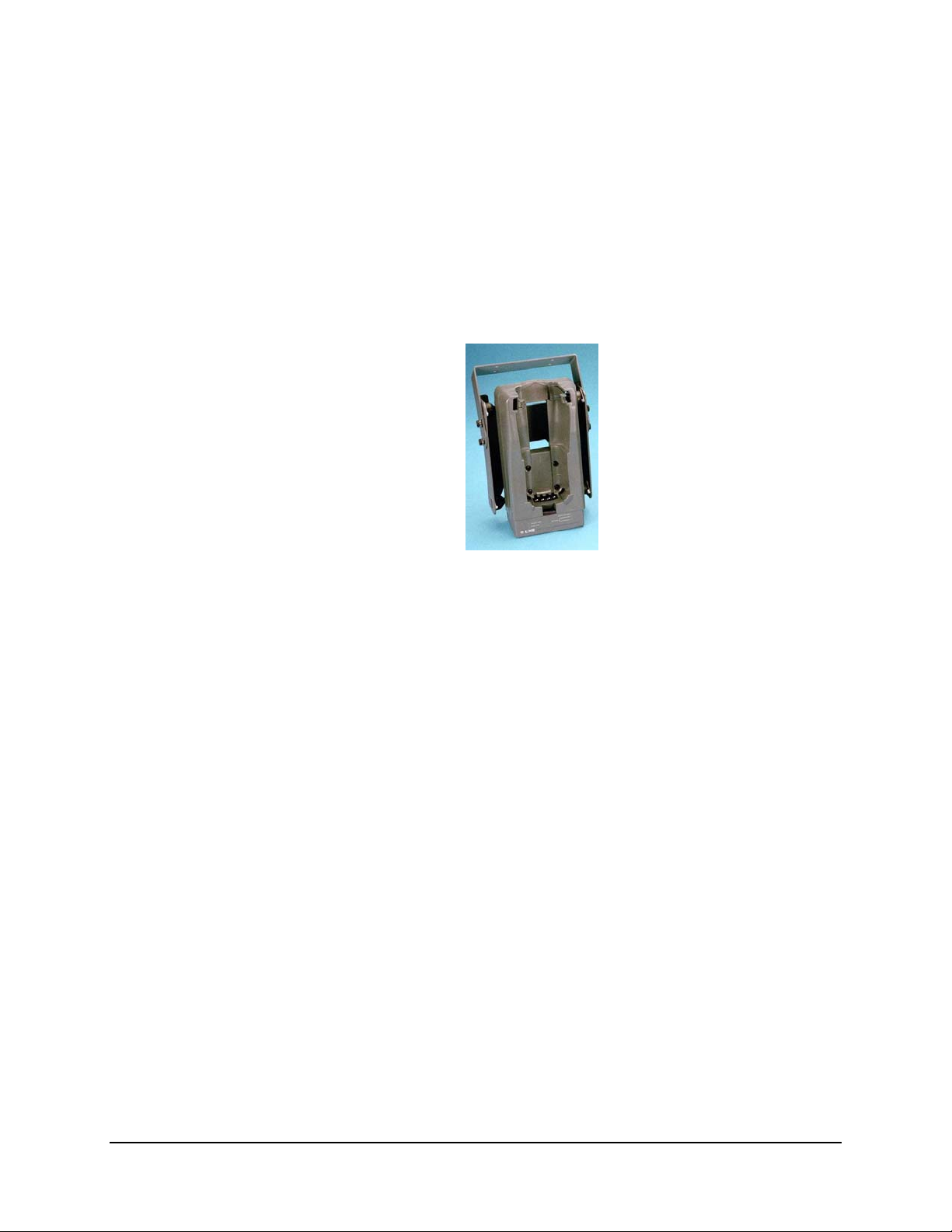
Single Docking Cradle
The Single Docking Cradle is designed to provide power, battery charging and standard data
communication for the LXE 2330, 2335 and MX1 devices while also providing ease of use,
serviceability and installation, modularity for future growth, and operation in harsh environments.
Chapter 1 Introduction
Figure 1-1 Vehicle Mount Docking Cradle Charging/Communicating Device
The Docking Cradle Family of chargers charge the Main Battery in the 2330, 2335 and MX1
while it is in the cradle.
The vehicle, wall or table mounted charger must have a Power/Charging Communications module
installed and be connected to an external power source before charging or communicating can
commence.
This guide provides information on the features and functionality of each of the components and
related accessories. Use this guide as you would any other source book: reading portions to learn
about the module, and then referring to it when you need more information about a particular
subject. This guide takes you through all aspects of the installation and configuration of the
desktop, vehicle and wall mounted cradles.
Features
Once installed and configured, the docking cradle could function as a:
• Simple holding device when the hand-held computer is in use or stored at the end of the
day.
• Quick charge (3½ hour) battery charger at the end of normal work periods.
• Constant power source for the computer while it is operating or stored in the cradle.
• Data transfer communications device using either the computer’s IR port or the docking
cradle RS232 port.
E-EQ-MX1DKRG-B MX1 Cradle Reference Guide
Page 10
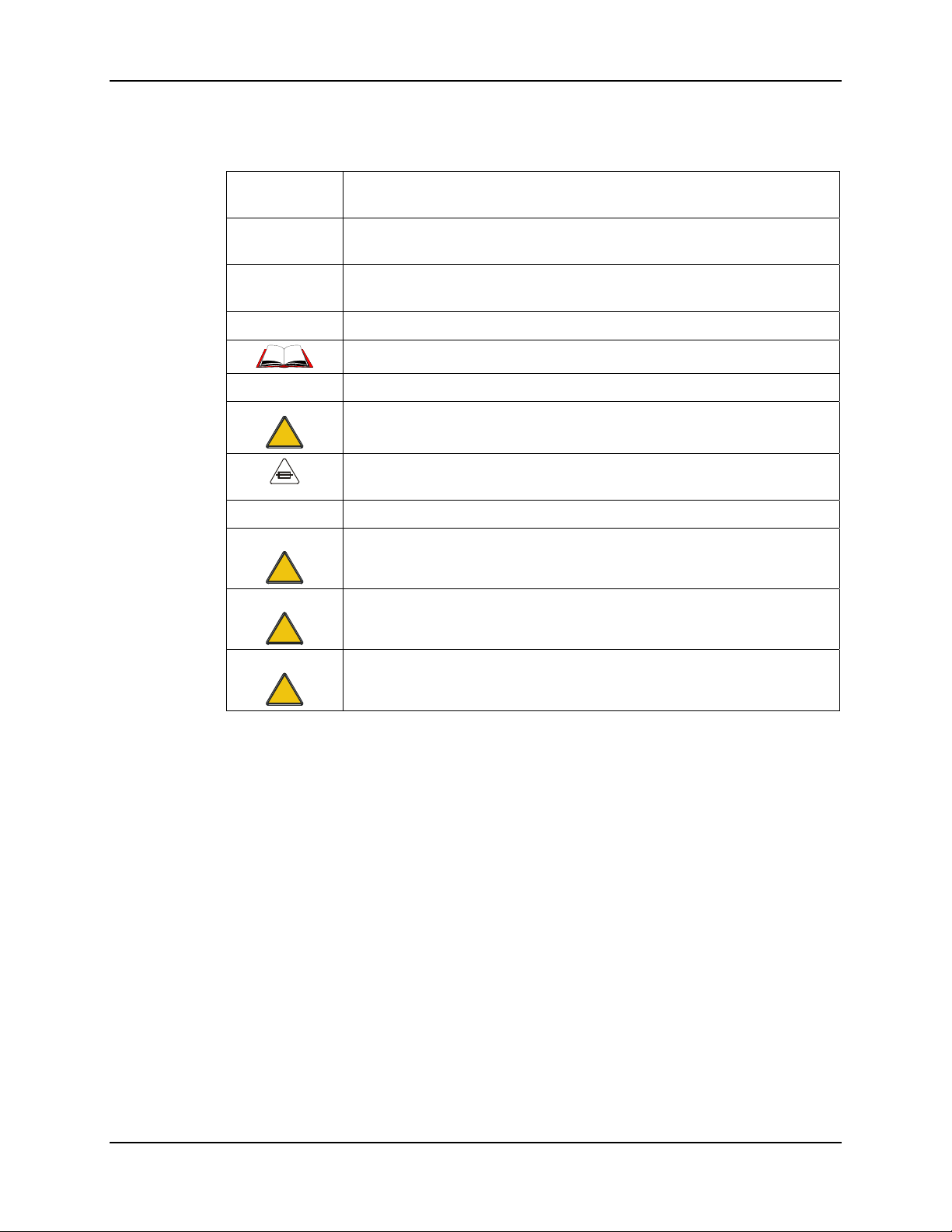
2 Document Conventions
Document Conventions
ALL CAPS All caps are used to represent disk directories, file names, and application
names.
Menu|Choice Rather than use the phrase "choose the Save command from the File menu",
this manual uses the convention "choose File|Save".
"Quotes" Indicates the title of a book, chapter or a section within a chapter (for
example, "Document Conventions").
< > Indicates a key on the keyboard (for example, <Enter> ).
Indicates a reference to other documentation.
ATTENTION
!
Note: Keyword that indicates immediately relevant information.
Keyword that indicates vital or pivotal information to follow.
Attention symbol that indicates vital or pivotal information to follow. Also,
when marked on product, means to refer to the manual or operator’s guide.
International fuse replacement symbol. When marked on the product, the
label includes fuse ratings in volts (v) and amperes (a) for the product.
Caution:
WARNING
DANGER
Keyword that indicates a potentially hazardous situation, which, if not
!
!
!
avoided, may result in minor or moderate injury.
Keyword that indicates a potentially hazardous situation, which, if not
avoided, could result in death or serious injury.
Keyword that indicates an imminent hazardous situation, which, if not
avoided, will result in death or serious injury.
MX1 Cradle Reference Guide E-EQ-MX1DKRG-B
Page 11
Quick Start 3
Quick Start
Note: Always store unused mobile devices with a fully charged main battery pack installed.
LXE recommends the mobile device be connected to an external power source
periodically to retain optimum power levels in the main battery pack and the backup
battery.
This section’s instructions are abbreviated and based on the assumption that your new docking
cradle is pre-configured and requires only mounting and a power source.
How To
1. First, assemble all docking cradle components.
2. Attach the docking cradle to the mounting brackets.
3. Install the docking cradle on a stable surface using the mounting brackets.
4. Connect all cables.
5. Connect the docking cradle to a power supply.
6. Turn the docking cradle on.
7. Last, insert a 2330, 2335 or MX1 in the docking cradle.
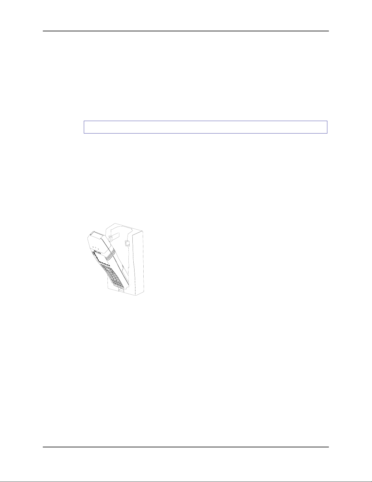
The mobile device (with or without the hand trigger-grip) pushes
into the cradle tail first and can be removed or inserted with one
hand. The device is inserted with the display facing out and is held
in the cradle with flexible side clips.
The cradle supports the device with any endcap option and pistol
grip and/or hand-strap installed.
Figure 1-2 Insert Device into Cradle
E-EQ-MX1DKRG-B MX1 Cradle Reference Guide
Page 12
4 Quick Start
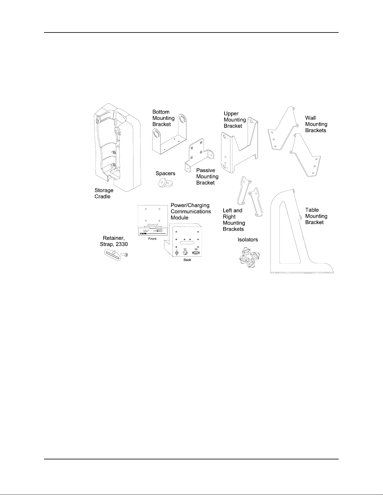
There are three primary components of the single docking cradle:
• Passive Storage Cradle
• Power/Charging and Communications Module
• Mounting Brackets (Wall, Table or Vehicle)
Figure 1-3 Wall, Vehicle and Desk Cradle Components
MX1 Cradle Reference Guide E-EQ-MX1DKRG-B
Page 13
Compatible Devices 5
Compatible Devices
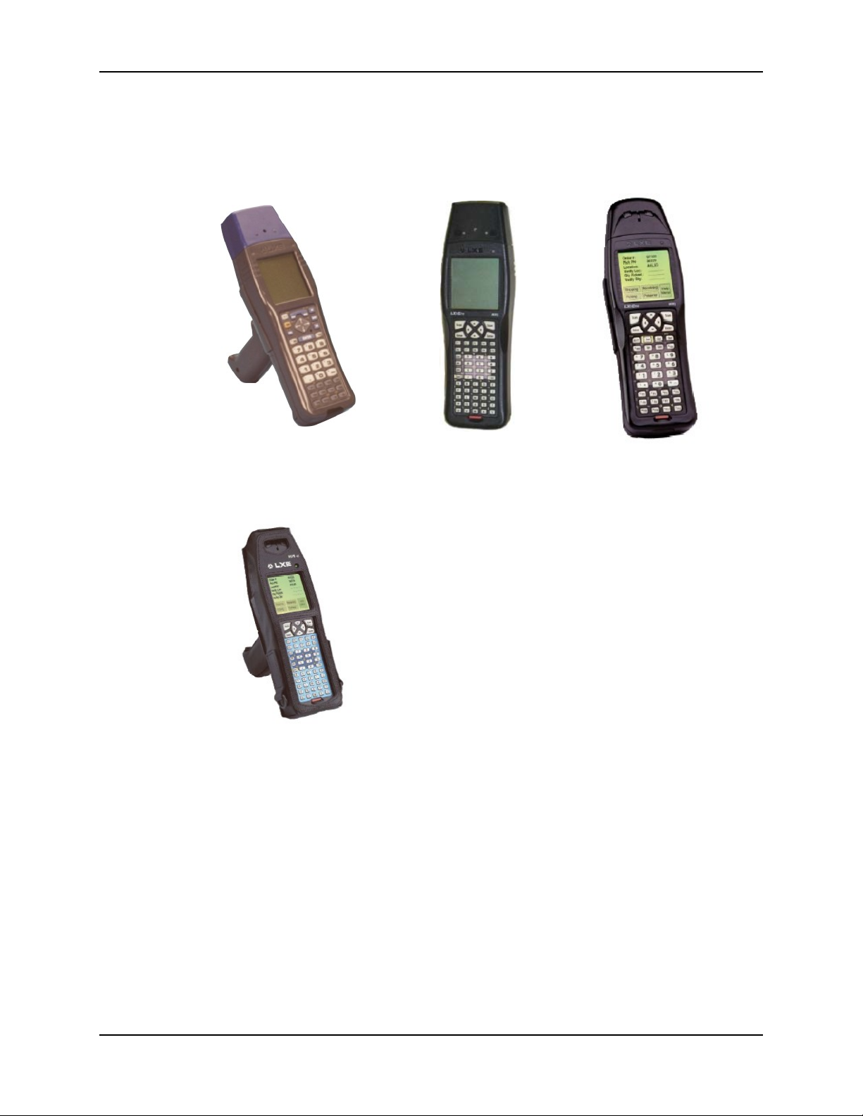
The docking cradles can be used in independent or combined configurations with these devices:
2330 2335 MX1
Figure 1-4 Compatible Devices
Attention:
The MX1 Intrinsically Safe device and battery pack
are NOT compatible with the MX1 Docking Cradle
and may cause damage to the MX1-IS and battery
pack if placed in an unauthorized MX1-IS docking
cradle/charger. The MX1-IS keypad is bright blue in
color.
MX1 I-Safe
E-EQ-MX1DKRG-B MX1 Cradle Reference Guide
Page 14
6 Compatible Devices
Battery Charging Contacts
Battery Charging
Contacts
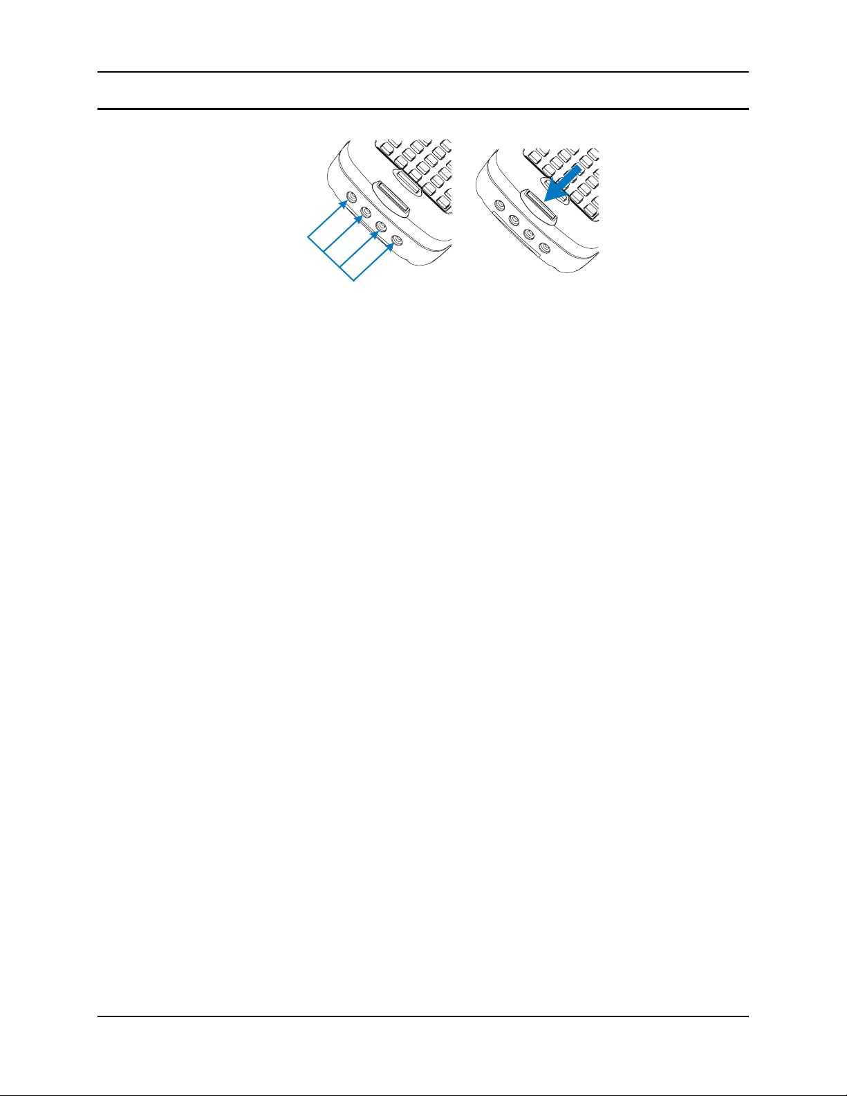
Figure 1-5 Cradle Connectors on the Hand Held Devices
There are a row of charging contacts located on the bottom of the 2330, 2335 and MX1.
Charging Cradle Connector
They are designed to provide charging voltage to the main battery pack when the unit is placed in
a charging station connected to an external power supply.
IR Port
Just above the battery charging contacts is the IR port. Data from the computer is sent/received
through the IR port to the cradle’s IR Port to/from the cabled host connection on the cradle.
IR Port
MX1 Cradle Reference Guide E-EQ-MX1DKRG-B
Page 15
Obsolete Equipment 7
Obsolete Equipment
As equipment is placed on the obsolete list (quite often due to the rapidly changing nature of the
RF environment and the improvements in computer hardware), LXE makes every effort to
support, service and repair the equipment until it is no longer repairable/serviceable. The
information contained in this document relating to obsolete devices has been made available as a
courtesy to LXE's customers.
Please contact your LXE customer support representative for assistance with these units and for
replacement equipment and software.
The 2335 and MX1 are obsolete as of December 2005. The 2330 is obsolete as of May 2000.
Software/Hardware Upgrades Required for the 2330 only
The following upgrades are available for 2330’s that will be used with the docking cradle.
• A 2330 without an “M” in the product serial number must be returned to LXE for upgrade
before using the 2330 in the Docking Cradle. The serial number is located on the LXE
product identification tag on the back of the 2330.
• Rev. C CPU upgrade to the 2330 is performed at LXE.
• RetroFit Kit, LXE part number 154873-0001, upgrade to the 2330 is performed at LXE.
Please contact LXE Customer Support at 770-449-0154 to determine if your 2330 requires
upgrading.
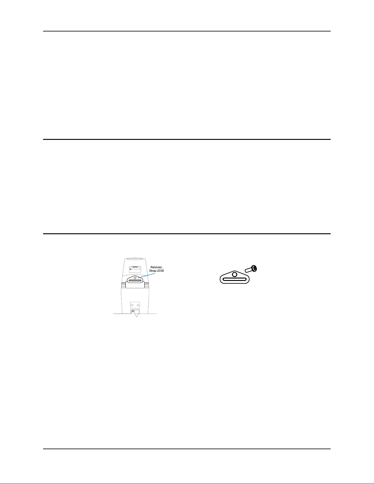
Retainer Clip for 2330 Required
Each 2330 that is to be placed in the cradle must have a Retainer installed.
Note: If the 2330 has a hand strap installed already, you do not need to perform this step.
Turn the mobile device off, if necessary, and place the mobile device face down on a flat surface.
Position the retaining strap bracket on the mobile device as shown below.
Insert the flat head screw and tighten securely.
The Screw part number is: 711205-1716
The Retainer part number is: 153852-0001
E-EQ-MX1DKRG-B MX1 Cradle Reference Guide
Page 16

8 Maintenance
Maintenance
Storage Cradle
Replace the storage cradle once a year.
The cradle is replaced at no charge during a Preventive Maintenance Inspection.
Check the cradle regularly for excessive wear at pressure points. If the cradle becomes cracked or
broken at any time, it must be taken out of service and replaced. Contact LXE Customer Service
for replacement cradle.
Vehicle Mount Assembly
Check the vehicle bottom bracket fasteners and re-tighten if necessary. If the vehicle bracket and
cradle connections become broken, loose or cracked, it must be taken out of service and replaced..
Pay particular attention to the condition of the rubber vibration isolators. If the rubber isolators
become damaged in any way, the vehicle bracket must be taken out of service and the isolators
replaced.
MX1 Cradle Reference Guide E-EQ-MX1DKRG-B
Page 17

Docking Cradle Configurations 9
Docking Cradle Configurations
The docking cradle components are designed to provide the following functions whether the
docking cradle is mounted to a wall, table or vehicle:
• Secure the mobile computer while ensuring vibration/shock isolation.
• Provide operational and battery charging power to the mobile computer.
• Provide IR to RS232 communication and IR “pass-through” with the mobile computer.
The docking cradle has four basic configurations. Additional combinations are available
depending on the power supply and cable accessory selected. See “Accessories” for part numbers.
Table/Wall Mount Passive Storage Cradle
Stand-alone unit to retain mobile device on table or wall.
Table/Wall Mount Power/Charging and Communications Module (PCM)
Passive storage cradle and PCM for power, recharge and communications capability.
Vehicle Mount with Passive Cradle
Passive storage cradle and vehicle mounting bracket for mobile use.
Vehicle Mount Power/Charging and Communications Module (PCM)
Passive storage cradle, PCM, and vehicle mount bracket for mobile power, recharge and
communications capability.
Add on modules and accessories include:
Power/Charging and Communications Module (PCM)
Provides power and battery charging to the mobile device, IR pass-through and IR to
RS232 conversion. A passive storage cradle is required.
Vehicle Mounting Bracket
Provides vibration isolation between vehicle and passive storage cradle. Attaches to passive
storage cradle and mounts to vehicle.
Power Supplies (only one is required)
LXE 110-240VAC input, 12VDC output power supply.
LXE 24-60DC input, 12VDC output power supply.
Circular connector to bare wire cable (12VDC input only).
Cables
DB9 to DB25 for connecting PCM to printer or computer.
DB9 to DB9 for connecting PCM to printer or computer.
DB9 to circular DIN for connecting PCM to Renegade printer.
Strap Retainer for each mobile device that will be using the cradle.
E-EQ-MX1DKRG-B MX1 Cradle Reference Guide
Page 18
10 Docking Cradle Configurations
Docking Cradle Components
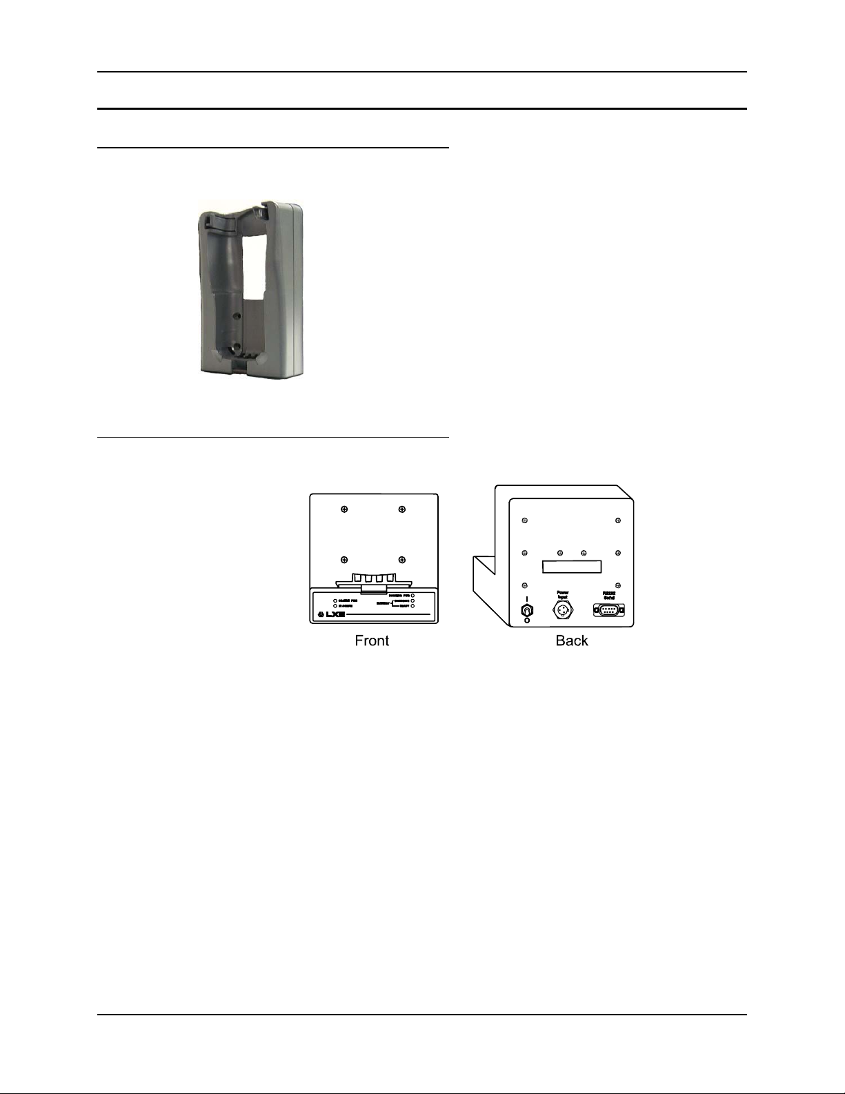
Passive Storage Cradle
The passive storage cradle is designed to support and protect the
mobile device. The device can be fully operational while in the
cradle, including display, keyboard and RF operation.
Figure 1-6 Passive Storage Cradle
Power/Charging and Communications Module
Figure 1-7 Power/Charging and Communications Module
The Power/Charging and Communications Module (PCM) attaches to the bottom and rear of the
passive storage cradle. It provides several electrical functions required by the mobile device
including:
• Power subsystem for operational and battery pack charging power, as well as power for
PCM digital circuits.
• Battery charger for the battery pack.
• IR to RS232 interface to connect the mobile device’s IR port to external cabled serial
devices.
A contact block on the PCM passes operational and charging power to the mobile device.
MX1 Cradle Reference Guide E-EQ-MX1DKRG-B
Page 19

Docking Cradle Configurations 11
Power Subsystem
The power subsystem is designed to accept input power from a vehicle’s battery or add-on DC
power supply and then provide power to the mobile device, including charge power to the built-in
battery pack. In addition, standard wall AC power can be used with an AC-to-DC converter.
It has an input power filter to help limit voltage spikes and noise from the vehicle battery input
voltage. A toggle switch disconnects the PCM from the external power source.
The power subsystem accepts power from the following external power sources:
• Universal input (120/240VAC) AC to DC power supply providing 12VDC output into the
docking cradle.
• 24 to 60VDC input DC to DC power supply providing 12VDC output to the docking
cradle.
• 8 to 18VDC input directly from truck or forklift battery power.
The power subsystem provides current limit protection for the PCM circuits and the mobile
device. A 4.0 Amp, Fast-blo fuse protects the PCM circuits, while a 1.1 Amp, self-resetting fuse
protects the mobile device. Fuses are not user replaceable.
Battery Charging Subsystem
The battery charging subsystem is used to charge the Nickel-Metal Hydride (NiMH) battery pack,
while the battery pack is installed in the mobile device. Total charge time is 3.5 hours when fast
charging. It delivers a constant current of 350mA to the battery pack at 8VDC maximum charging
voltage.
The charger automatically switches from fast charge mode to trickle charge mode, upon
completion of fast charging. Trickle charge provides 30mA current to the battery pack, to help
sustain battery pack capacity and prevent self-discharge. The charger monitors the battery pack
temperature to control fast charge termination.
Prior to and during fast charge, the battery charger monitors battery temperature and voltage as a
safety feature. If battery temperature and voltage are not within acceptable ranges, the battery
charger will remain in the trickle charge mode.
The charger also provides control signals for the battery charger indicator LEDs on the front of
the PCM:
• Fast Charge in Progress,
• Fast Charge Pending,
• Fast Charge Complete/Trickle Charge Active and
• Battery Absent/Fault.
The charger also provides over-current protection to the mobile device’s battery pack, via a 1.1
Amp self-resetting fuse. Fuse is not user replaceable.
IR to RS232 Interface
The IR-RS232 interface converts IR formatted input data transferred between the docking cradle
and the mobile device, into RS232 formatted serial output data, for transfer with an external
cabled serial device (such as a printer or laptop computer). This interface also provides a control
signal for visual indication of IR and RS232 data transmission: the IR Active LED is green when
IR - RS232 transmission is in progress.
E-EQ-MX1DKRG-B MX1 Cradle Reference Guide
Page 20
12 Docking Cradle Configurations
The IR portion of the interface is IrDA-SIR 1.0 compatible with the exception of the range of
allowable data rates. The IR data transmission rate default value is 9600 bps, and is fixed at
this rate. The IR operating envelope has a distance range of 2 cm (.79 inches) to 1 meter (3.2
feet) with a viewing angle of 30 degrees. The IR interface is half-duplex, capable of data transfer
in only one direction at a time.
The RS232 portion of the interface is serial, half-duplex through the 9-pin connector port. The
RS232 port provides the following serial data and handshaking control signals: TD, RD, CTS,
RTS, DTR, DSR and GND.
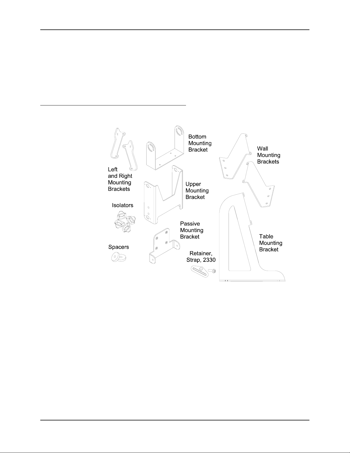
Mounting Brackets
Figure 1-8 Mounting Bracket Assemblies
The brackets provide vibration isolation and mount adaptation for both the mobile device and the
full docking cradle, including the passive cradle and PCM.
When mounted in the vehicle mounting bracket, the docking cradle can be rotated about the X
axis which accommodates user keypad accessibility and line-of-site IR port positioning. All
brackets have several pre-drilled mounting hole patterns to allow mounting to different
vehicles/surfaces.
MX1 Cradle Reference Guide E-EQ-MX1DKRG-B
Page 21
Powered Cradle Indicators 13
Powered Cradle Indicators
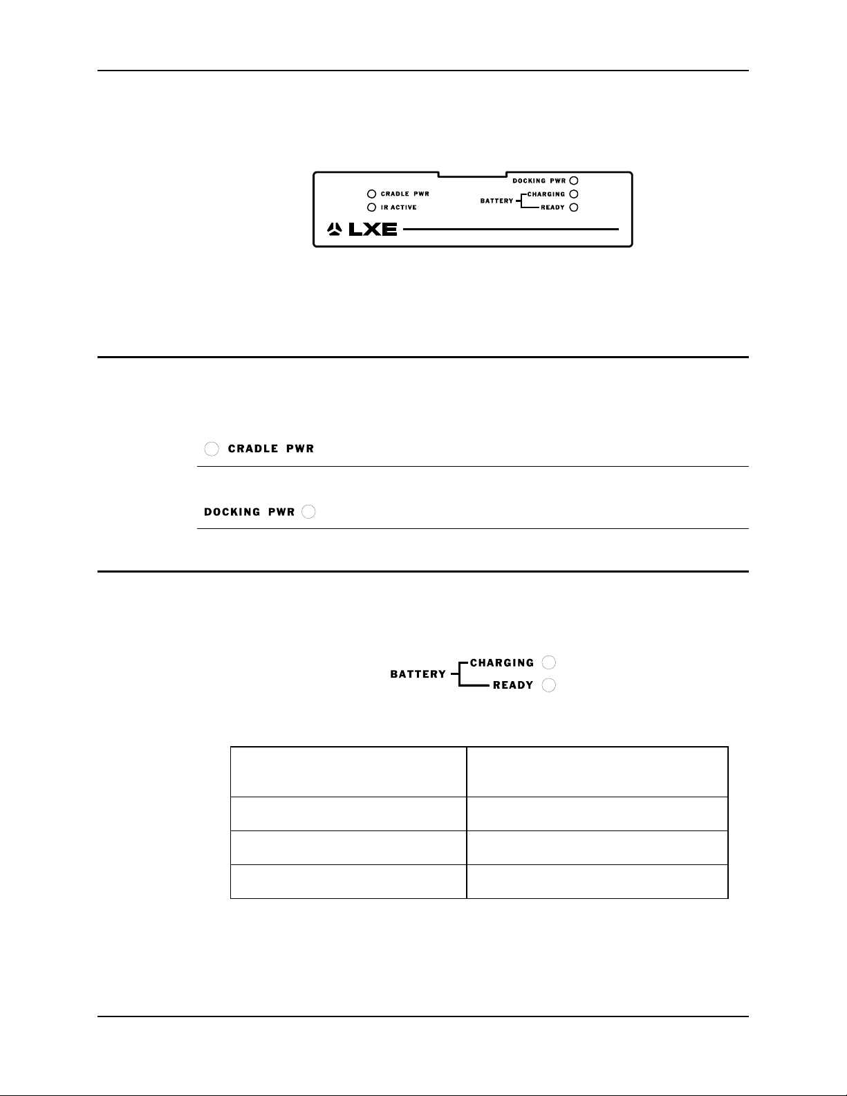
Figure 1-9 Status Indicators
Note: The docking cradle must have a Power/Charging and Communications Module installed
and connected to a power supply before these indicators are activated.
Power On
Note: The Power Switch must be ON and both indicators must be Green before the battery
pack in the mobile device can be charged.
Green
The CRADLE PWR indicator is green when receiving power from the +5VDC power supply.
The DOCKING PWR indicator is green when receiving power from the +12VDC power supply.
Battery Charging Status
Battery charging status is indicated by the BATTERY CHARGING and the BATTERY READY
indicators.
READY indicator is ON Fast Charge Complete /
CHARGING indicator is ON Fast Charge in Progress
CHARGING indicator is BLINKING Fast Charge Pending
CHARGING is Off, READY is Off Battery Absent / Fault
Green
Figure 1-10 Battery Charging Status Indicators
Trickle Charge Active
Note: The battery pack in the mobile device begins charging as soon as it is placed in the
docking cradle regardless of the mobile device’s On/Off status.
E-EQ-MX1DKRG-B MX1 Cradle Reference Guide
Page 22
14 Cradle Connectors
IR-RS232 Status
Both IR and RS232 receive/transmit status is indicated by the IR ACTIVE indicator.
Figure 1-11 IR-RS232 Status Indicator
The indicator is ON when actual data transmission is occurring and is OFF when no transmissions
are in progress.
Note: The mobile device must be ON before IR-RS232 transmission can occur.
Cradle Connectors
Power Switch, Power Cable and RS232 Connector
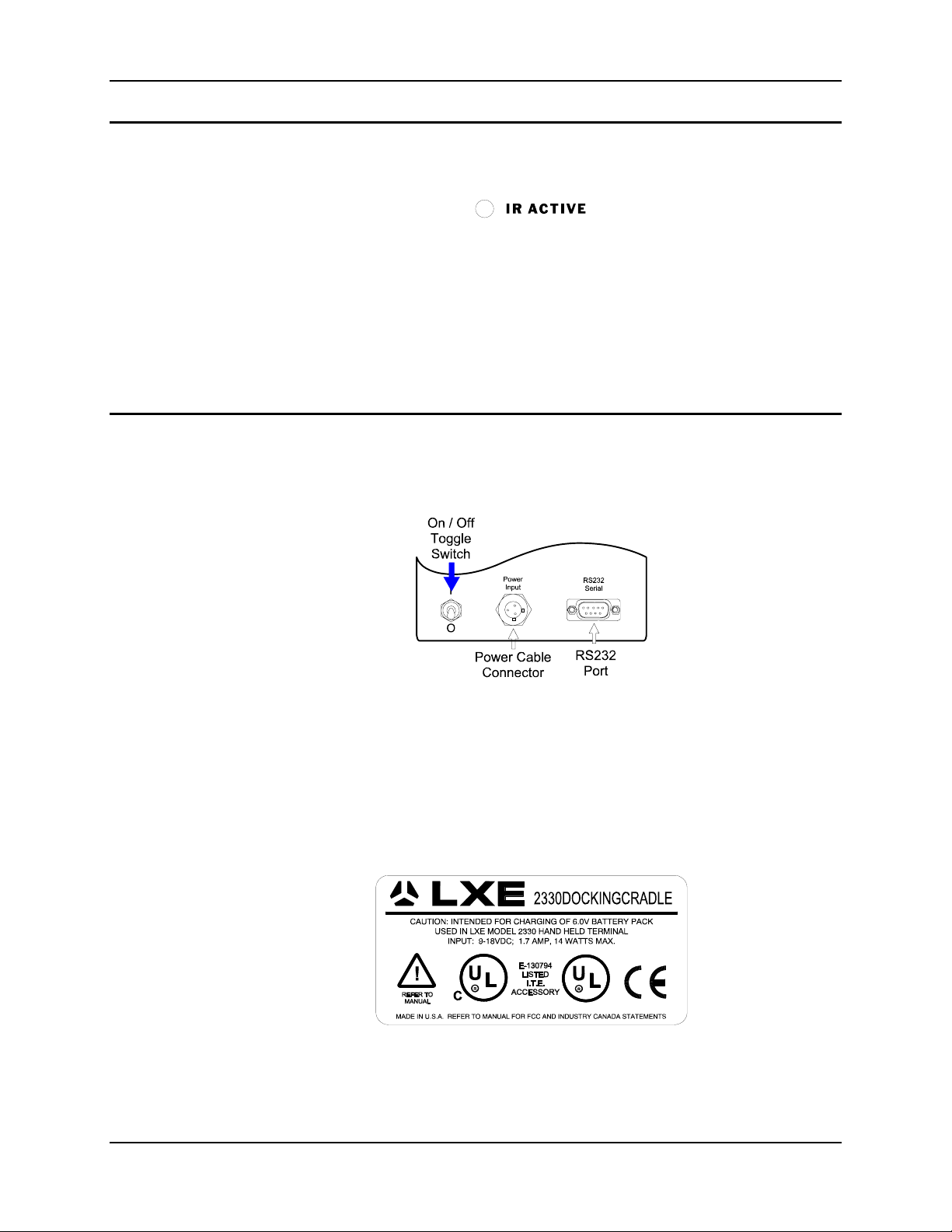
The power switch, power cable and RS232 cable connectors are located at the back of the PCM
on the Docking Cradle.
ON Toggle switch is UP. ( I )
OFF Toggle switch is DOWN. ( O )
Docking Cradle Label
Figure 1-12 On/Off Switch and Cable Connectors
Figure 1-13 Nameplate Label on Docking Cradle
MX1 Cradle Reference Guide E-EQ-MX1DKRG-B
Page 23
AC Adapters for Docking Stations (Optional) 15
AC Adapters for Docking Stations (Optional)
US AC Wall Adapter
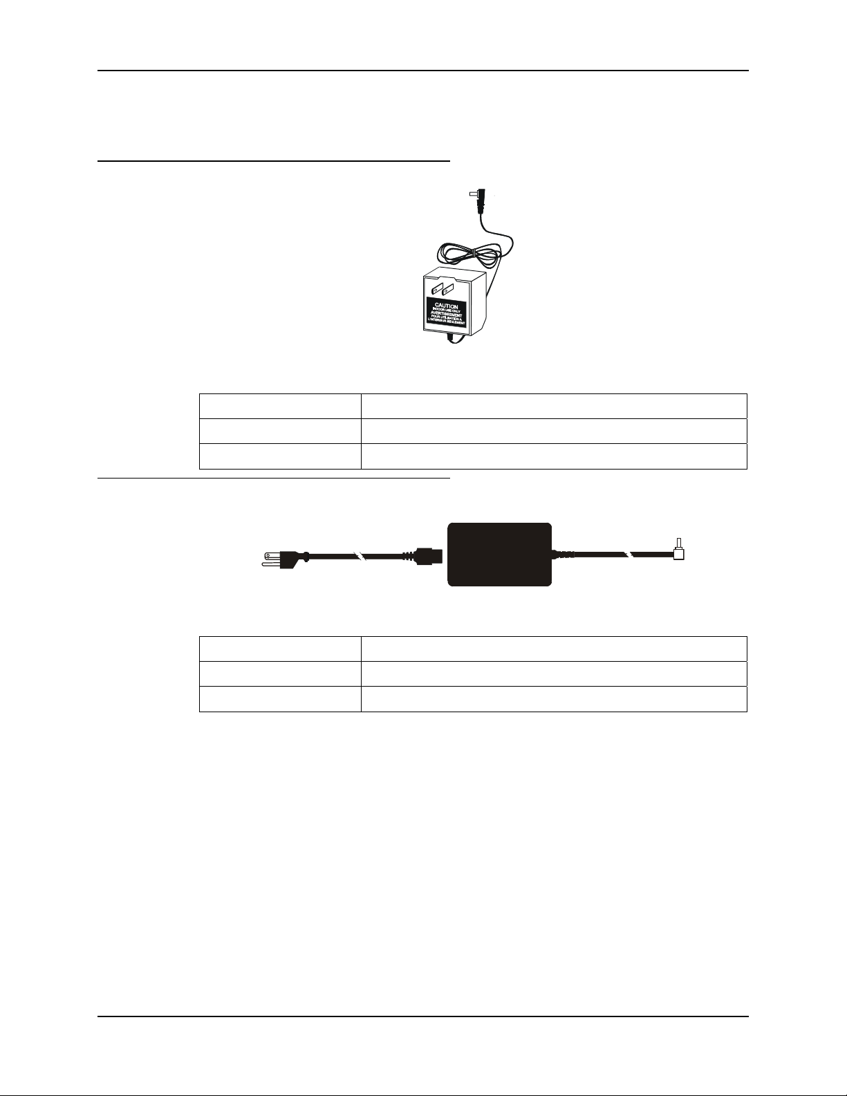
Figure 1-14 US AC/DC 12V Power Supply
Operating Temperature 32°F to 104°F (-0°C to 40°C)
Storage Temperature -22°F to 140°F (-30°C to 60°C)
Operating Humidity Up to 90% non-condensing at 104°F (40°C)
International AC Adapter
Operating Temperature 32°F to 104°F (-0°C to 40°C)
Storage Temperature -22°F to 140°F (-30°C to 60°C)
Operating Humidity Up to 90% non-condensing at 104°F (40°C)
Figure 1-15 International AC/DC 12V Power Supply
E-EQ-MX1DKRG-B MX1 Cradle Reference Guide
Page 24

16 Getting Help
Getting Help
LXE user guides are now available on CD and they can also be viewed/downloaded from the LXE
ServicePass website. Contact your LXE representative to obtain the LXE Manuals CD or access
to the LXE ServicePass website. You can also check the LXE ServicePass website for the latest
manual releases.
Note: Obsolete/archived manuals are not available on the LXE Manuals CD. They are
available for download from the ServicePass website only.
You can get help from LXE by calling the telephone numbers listed on the LXE Manuals CD, in
the file titled “Contacting LXE”. This information is also available on the LXE website.
Explanations of terms and acronyms used in this manual are located in the file titled “LXE
Technical Glossary” on the LXE Manuals CD and on the LXE website.
User Guides
Note: The 2330, 2335 and MX1 are obsolete. The 900MHz radio used in these mobile devices
is obsolete. Please contact your LXE representative for replacement devices.
2330 Installation and Operator’s Guide *
Accessories
2330 Reference Guide *
MX1 (2335) User’s Guide *
MX1 (2335) Reference Guide
MX1 User’s Guide *
MX1 Reference Guide *
2330 Multidock Reference Guide *
Getting the Most From Your Batteries
AC Singledock Desk Mounting Instruction *
DC Singledock Vehicle Wiring and Mounting Instruction *
2330 Table Mounting Bracket Installation *
2330 Vehicle Mounting Bracket Installation *
2330 Wall Mounting Bracket Installation *
* User guides that have been archived are available on the LXE ServicePass Website. All others
are available on the LXE Manuals CD as well as on the LXE Website.
Cradles
Passive Table (mounted on table/wall) Cradle 2330A004STORCRADLE
Powered Table (mounted on table/wall) Cradle 2330A006PCCRADLE
Passive VMT (mounted in vehicle) Cradle 2330A007VMCRADLE
Powered VMT (mounted in vehicle) Cradle 2330A009PCVMCRADLE
Power Supply
Power Module Upgrade 2330A003PCMODULE
MX1 Cradle Reference Guide E-EQ-MX1DKRG-B
Page 25

Getting Help 17
Power Adapter, Bare Wire 12 VDC 1300A053CBL12ML3
Power Adapter, 24-60 VDC, 20 Watts 1300A301PS24WW
Power Adapter, 110-240 VAC 1300A303PSACWW
Battery, 1500mAh, NiMH 2330A381BATT1500
Multidocks
4 Bay Comm Power Multidock 2330A013MULTIDOCK
4 Line Communications Co-Processor 9000A063COMMPROC4
SingleDocks
Single Comm Power Dock (AC) 2330A010ACSINGDOCK
Single Comm Power Dock (DC) 2330A011DCSINGDOCK
Brackets
VMT Bracket Upgrade 2330A001BRKT
Vehicle Bracket Kit for DC Singledock 2330A012VMTBRKT
Bracket, Dock, Desk Mounting 2330A018DOCKDESKMTG
Bracket, Dock, Raised Wall Mounting 2330A020DOCKRAISED
Peripheral Device Cables
D9 to D25 Printer/PC Cable, 6ft 9000A053CBL6D9D25
D9 to D9 PC Cable, 6ft 9000A054CBL6D9D9
D9 to DIN Renegade Cable, 6ft 9000A055CBL6DIN8D9
Cable, Multidock, DA9F-DA9F, Multi-Multi 9000A058CBLD9D9MULTI
Cable, Null Modem, DA9F-DB25F,
6200L200
Single/Multi
Cable, Straight Thru, DB25F-DB25M 6200L201
Cable, Null Modem, DB25F-DB25F,
6200L202
Single/Single
Miscellaneous
RS232 to RS485 Converter 2330A015CONV232485
RS485 Terminator, 115K Baud 2330A016RS485FAST
RS485 Terminator, 9.6K Baud 2330A017RS485SLOW
Battery Chargers
6 Unit Charger/Analyzer 2330A378CHGR6WW
3 Unit Battery Analyzer 2330A379ANLZR3WW
Portable Charger, Clip-On (see Note) 2335A376PORTACHGR
Note: Must order one Power Supply (9000A303PSCIGLTADPT) with each Portable Charger.
E-EQ-MX1DKRG-B MX1 Cradle Reference Guide
Page 26

18 Getting Help
MX1 Cradle Reference Guide E-EQ-MX1DKRG-B
Page 27
Introduction
Chapter 2 Installation
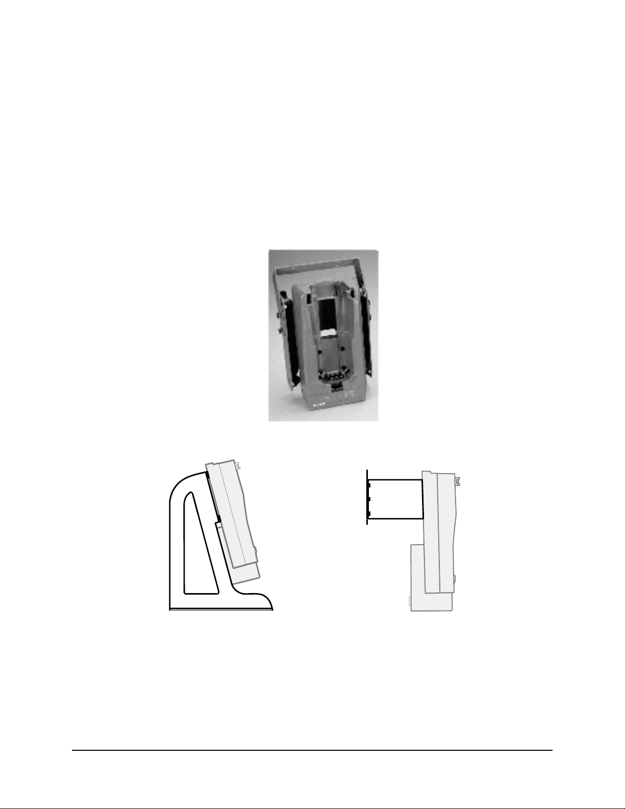
The cradle is attached to the mounting assembly then installed on a flat, stable stationary or
mobile surface. Four isolation supports on the mounting bracket provide vibration mounting for
the mobile computer and PCM.
Power cables, and any required RS232 cable, are then connected to the Power Module.
Vehicle Mount
Table Mount Wall Mount
Figure 2-1 Vehicle, Desktop and Wall Mounted Cradle Components
E-EQ-MX1DKRG-B MX1 Cradle Reference Guide
Page 28

20 Before Assembly Begins
Foreign Language Translations
This chapter contains assembly instructions in English only. The assembly instructions have been
translated into the following languages:
• French
• German
• Italian
• Portuguese
• Spanish
• Swedish
Please refer to the following documents, available on the LXE website in the Archived section, for
the translated text:
Vehicle “2330 Docking Cradle Vehicle Mounting Bracket” Installation Instruction Sheet
(DocID 2330A142INSTVEH).
Table “2330 Docking Cradle Table Mounting Bracket” Installation Instruction Sheet
(DocID 2330A140INSTTBL).
Wall “2330 Docking Cradle Wall Mounting Bracket” Installation Instruction Sheet
(DocID 2330A141INSTWALL).
The Multidock and AC/DC docking stations arrive already assembled.
Before Assembly Begins
Unpack the shipping container and verify the components for the mounting bracket to be installed
are present.
MX1 Cradle Reference Guide E-EQ-MX1DKRG-B
Page 29
General Components 21
General Components
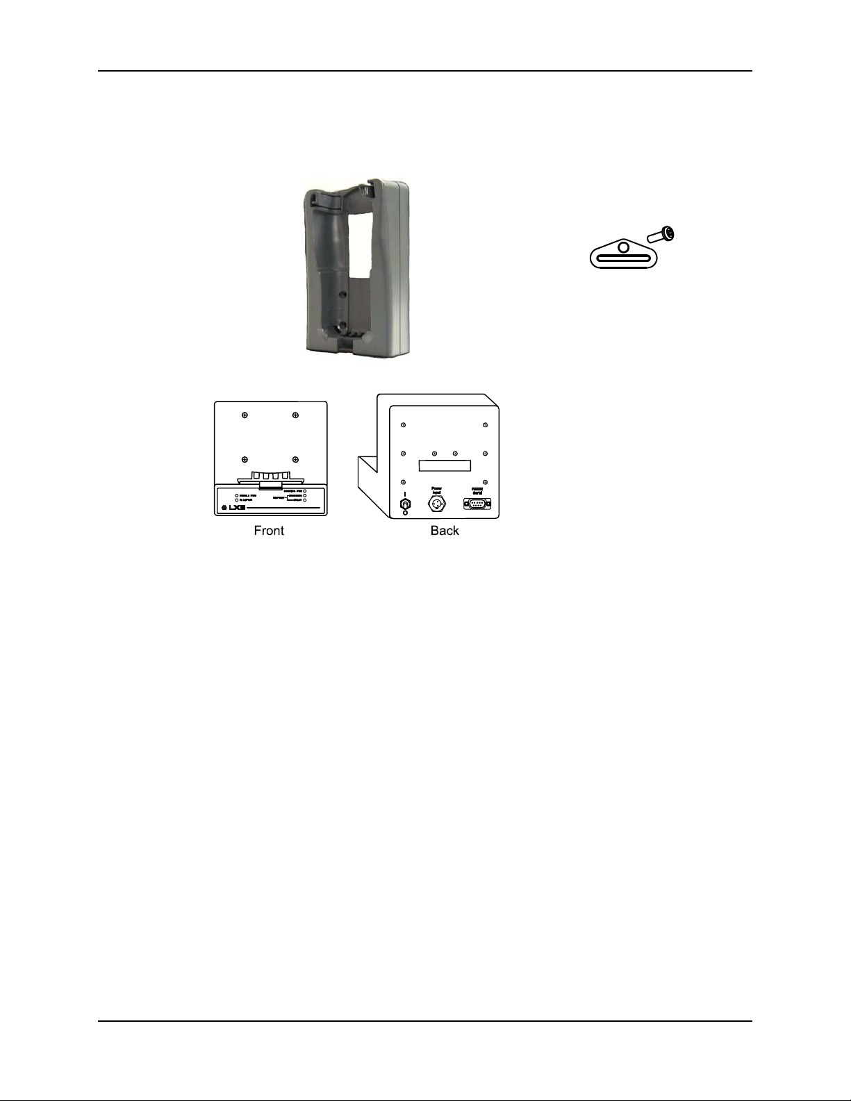
Verify you have the following general assembly components:
Retainer, Nylon Hand Strap for
mobile device (if needed)
1 each 6-32 x 3/8 Flat Head Screw
Passive Storage Cradle
Torquing tool needed to attach PCM to cradle is not supplied by LXE. You will need a
torquing tool capable of torquing to 8±1 in/lb (.90±.11 N/m) when attaching the
Power/Communications Module to the cradle.
See the following sections for components that are unique to the docking cradle’s use.
Note: Bolts, washers and wrench required to attach the mounting brackets to the surface are
not supplied by LXE.
Power/Communications Module
(if ordered)
For cradle power, mobile device
recharge and communications
capability.
4 each #8 Flat Washer
4 each #8 Lock Washer
4 each 8-32 x ½ Pan Head Screw
E-EQ-MX1DKRG-B MX1 Cradle Reference Guide
Page 30
22 Vehicle Mount Components
Vehicle Mount Components
Clearance:
There must be at least 8” clearance at the back of the bracket for the trigger handle. Position the
bracket to allow access to the switches and ports on the back of the Power Module, if installed.
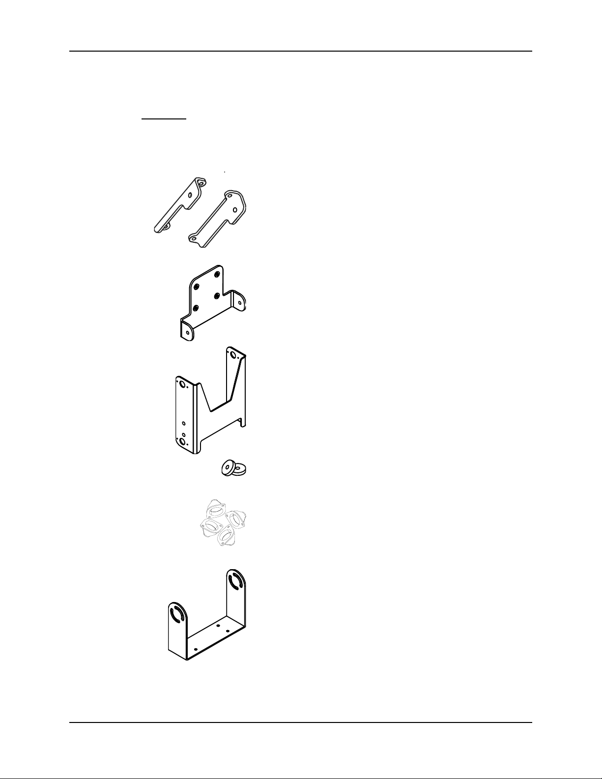
Left and Right Mounting Brackets
These brackets are attached to the back of the cradle.
4 each #8 Flat Washer
4 each #8 Lock Washer
4 each 8-32 x ½ Pan Head Screw
Passive Mounting Bracket
This bracket is attached to the back of the cradle when the cradle
does not have a Power Communications Module (PCM) installed.
4 each #8 Flat Washer
4 each #8 Lock Washer
4 each 8-32 x ½ Pan Head Screw
Upper Mounting Bracket
4 each #8 Lock Washer
2 each 8-32 x ½ Pan Head Screw
2 each 8-32 x ¾ Pan Head Screw
2 each Aluminum spacer
4 each Isolator
8 each Nut, Hex 4-40 Keps
MX1 Cradle Reference Guide E-EQ-MX1DKRG-B
Bottom Mounting Bracket
This bracket is mounted to the vehicle.
4 each 1/4 Flat Washer
4 each 1/4 Lock Washer
4 each ¼-20 Bolt
Page 31

Table Mount Components 23
Table Mount Components
Clearance:
There must be at least 8” clearance at the back of the bracket for the trigger handle. Position the
bracket to allow access to the switches and ports on the back of the Power Module, if installed.
Table Mounting Bracket
4 each #8 Flat Washer
4 each #8 Lock Washer
4 each 8-32 x ½ Pan Head Screw
4 each Rubber Feet
Wall Mount Components
Clearance:
There must be at least 8” clearance at the back of the bracket for the trigger handle. Position the
bracket to allow access to the switches and ports on the back of the Power Module, if installed.
Wall Mounting Brackets, 2 each
Left side and right side
4 each #8 Flat Washer
4 each #8 Lock Washer
4 each 8-32 x ½ Pan Head Screw
E-EQ-MX1DKRG-B MX1 Cradle Reference Guide
Page 32
24 Putting it all Together
Putting it all Together
Attach Power Communications Module to Cradle
Equipment Needed: Torque wrench capable of torquing to 8±1 in/lb (.90±.11 N/m) .
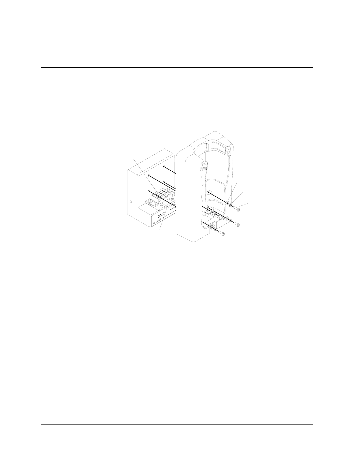
1. Holding the cradle securely in one hand and the power module in the other, slide the cradle
bottom onto the power communications module.
2. Position the battery contacts into the opening in the cradle bottom and the red IR port into the
front opening of the cradle.
Battery
Contacts
Flat Washer
Lock Washer
Pan Head
Screw
IR Port
3. Insert a Flat Washer, Lock Washer and Pan Head Screw into each of four holes.
4. Torque the Pan Head Screws to 8±1 in/lb (.90±.11 N/m).
Continue to the section for the cradle’s intended use; vehicle, desk or wall.
MX1 Cradle Reference Guide E-EQ-MX1DKRG-B
Page 33
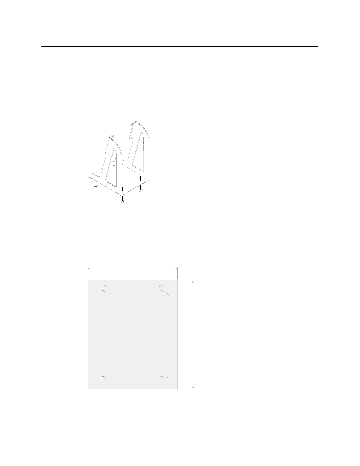
Putting it all Together 25
Table Mount Assembly
The table mounted cradle’s lower end is tilted forward at a 15° angle.
Clearance:
There must be at least 5” clearance (10 cm) at the back of the table mount bracket for the trigger
handle. Position the bracket to allow access to the switches and ports on the back of the Power
Module, if installed.
Assemble Movable Table Bracket
When the Table Bracket is to be placed on a flat
surface without the need for securing the bracket to
the surface, insert the Rubber Feet in the holes in
the base of the Table Bracket.
You are now ready to attach the cradle to the Table Bracket.
Assemble Stationary Table Bracket
Step 1 - Mount Table Bracket to Flat Surface
Important: Attach the table bracket to the table before attaching bracket to the cradle.
5.870 in
(14.91 cm)
3.870 in
(9.83 cm)
Using the dimensions on this
diagram, place the table bracket
on a flat surface.
Insert four ¼ bolts, or
5.618 in
(14.27 cm)
7.118 in
(18.08 cm)
equivalent, and tighten the bolts
securely.
Important: Mount to the most
rigid surface available.
Test the bolts frequently during
operation cycles and re-tighten
if necessary.
MOUNTING DIMENSIONS,
DESK MOUNT
(NOT TO SCALE)
E-EQ-MX1DKRG-B MX1 Cradle Reference Guide
Page 34
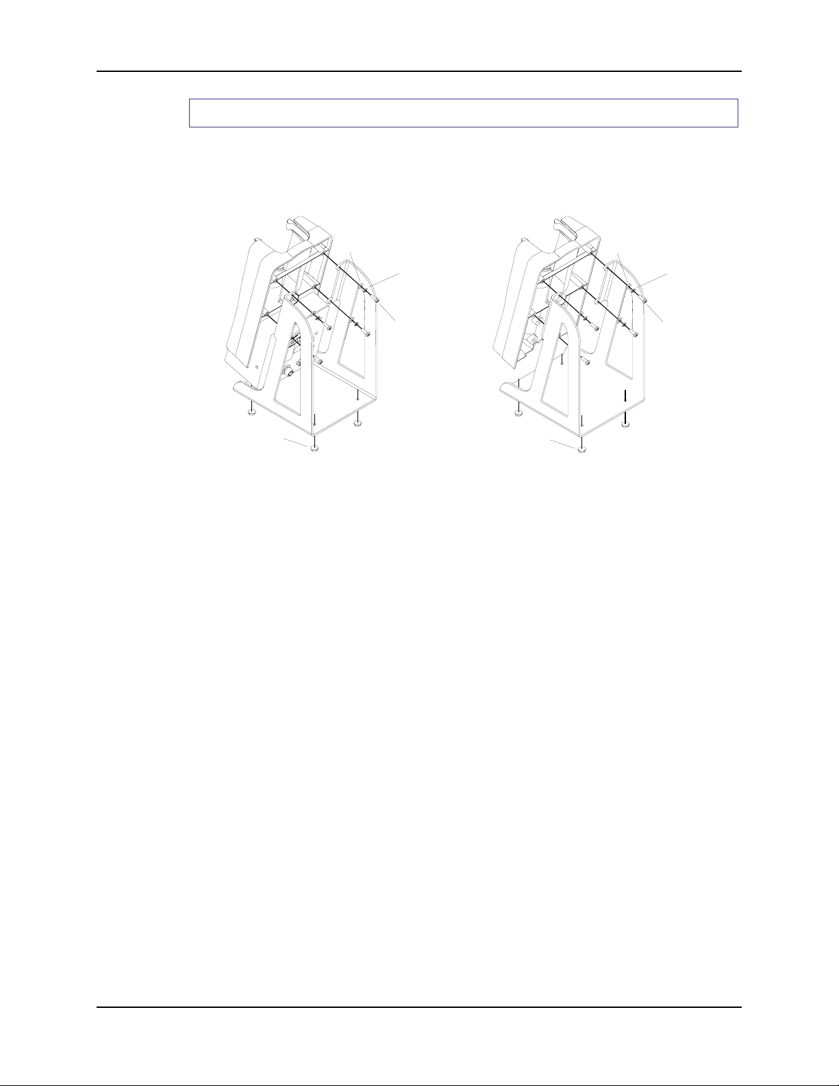
26 Putting it all Together
Step 2 - Connect the Cradle to the Table Bracket
1. If the mobile device is in the storage cradle, remove it from the cradle and place in a safe
location.
2. Turn the Power Module, if installed in the cradle, off and remove all cables from the Power
Module.
Rubber
Foot
Flat Washer
Lock Washer
Pan
Head
Screw
Rubber
Foot
Flat Washer
Lock Washer
Pan
Head
Screw
With Power Module Without Power Module
3. Place the cradle in front of the table bracket, aligning the upper screw holes in the back of the
cradle with the upper screw holes in the table bracket.
4. Insert the flat washer, lock washer and pan head screws in the cradle screw holes and torque
the Pan Head Screws to 8±1 in/lb (.90±.11 N/m).
5. The cradle is now ready to use. If a Power Module is installed in the cradle, reattach all cables
and turn the Power Module on.
MX1 Cradle Reference Guide E-EQ-MX1DKRG-B
Page 35
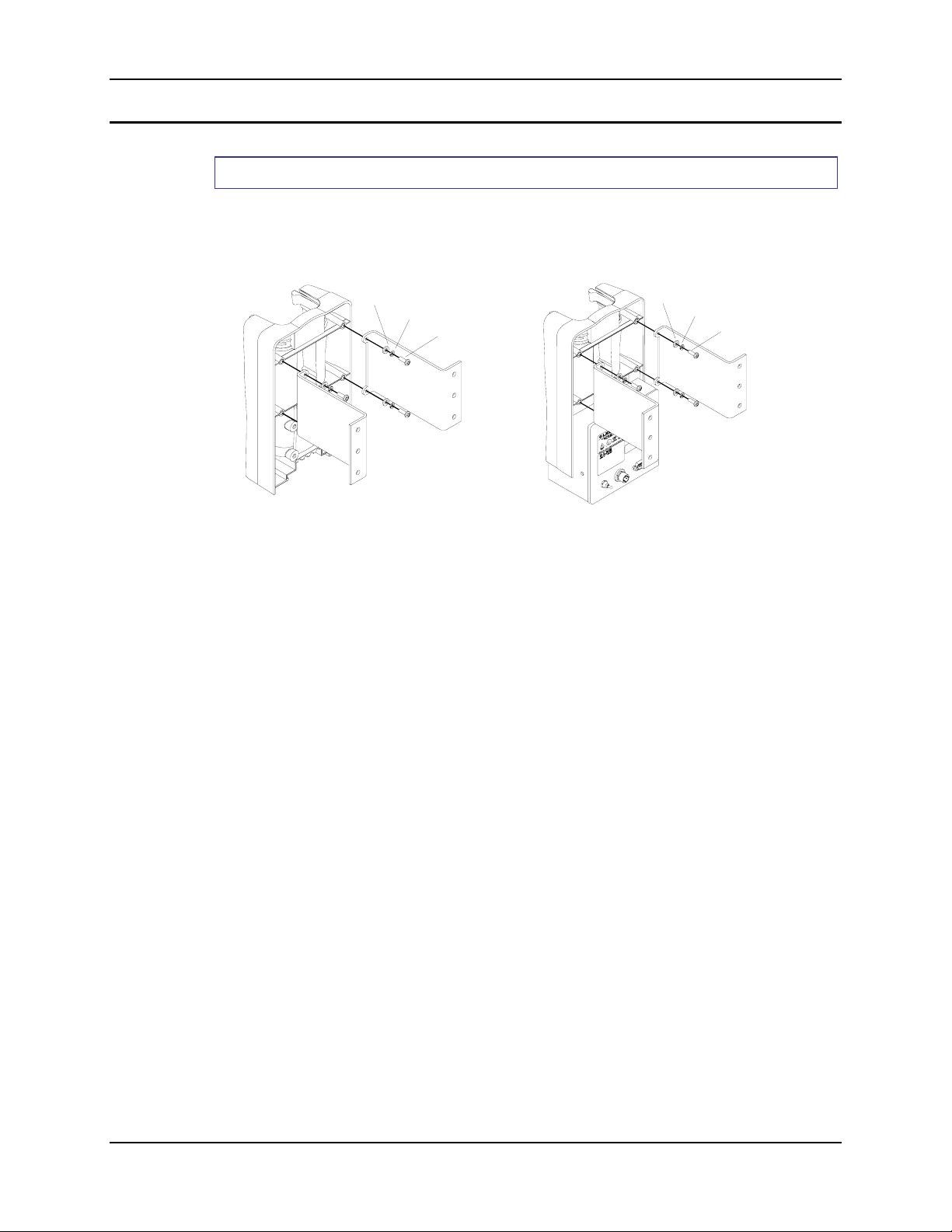
Putting it all Together 27
Wall Mount Assembly
Step 1 - Attach Brackets to Cradle
Important: Attach the brackets to the cradle before attaching brackets to the wall.
Equipment Needed: Torque wrench capable of torquing to 7 in/lb (.79 N/m) .
Flat
Washer
Lock
Washer
Pan
Head
Screw
Flat
Washer
Lock
Washer
Pan
Head
Screw
Without Power Module With Power Module
1. If the mobile device is in the storage cradle, remove it from the cradle and place in a safe
location.
2. Turn the Power Module, if installed in the cradle, off and remove all cables from the Power
Module.
3. Place the cradle face down on a stable surface.
4. Place a wall bracket on the cradle with the cradle end down and the wall end up.
5. Align the cradle screw holes in the back of the cradle with the cradle end screw holes in the
brackets.
6. Insert the flat washer, lock washer and pan head screws in the cradle screw holes and torque
the Pan Head Screws to 7 in/lb (.79 N/m).
You are ready to mount the wall brackets to the wall.
E-EQ-MX1DKRG-B MX1 Cradle Reference Guide
Page 36
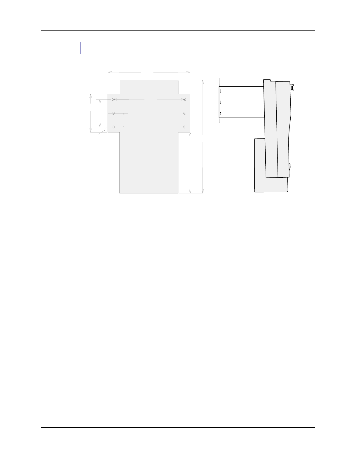
28 Putting it all Together
(
)
Step 2 - Mount Wall Brackets to the Wall
7.682 in
(19.51 cm)
6.682 in
3.566 in
(9.06 cm)
2.564 in
(6.51 cm)
1.282 in
(3.26 cm)
(16.97 cm)
5.669 in
(14.4 cm)
10.547 in
(26.79 cm)
.50 in
(1.27 cm)
MOUNTING DIMENSIONS,
WALL MOUNT
NOT TO SCALE
Important: Mount to the most rigid surface available.
1. Place the assembled cradle wall mounting on a vertical surface.
2. Insert four #10 bolts, or equivalent fasteners, in the wall end of the bracket and tighten
securely.
3. The cradle is now ready to use. If a Power Module is installed in the cradle, reattach all cables
and turn the Power Module on.
MX1 Cradle Reference Guide E-EQ-MX1DKRG-B
Page 37
Putting it all Together 29
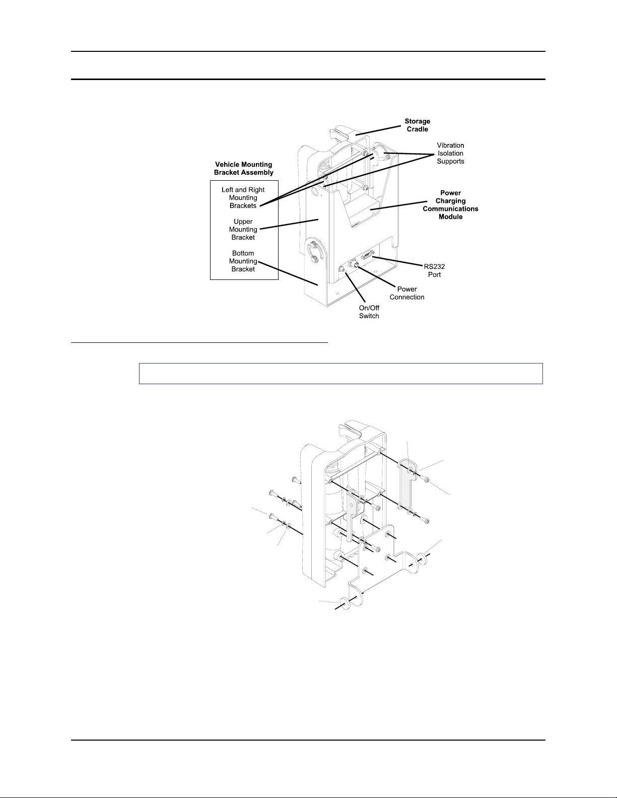
r
Vehicle Mount Assembly
Step 1 - Prepare Cradle
Cradle Without Power/Communications Module
Equipment Needed: Torque wrench capable of torquing to 8±1 in/lb (.90±.11 N/m).
Note: When there is no PCM in the cradle, the flat lower mounting bracket (passive bracket)
must be attached to the cradle.
Pan Head
Screw
Lock Washer
Flat Washer
Spacer
Flat Washer
Lock Washe
Pan Head
Screw
Spacer
E-EQ-MX1DKRG-B MX1 Cradle Reference Guide
Page 38
30 Putting it all Together
r
Attach the Passive Bracket
1. If the mobile device is in the storage cradle, remove it from the cradle and place in a safe
location.
2. Place the passive cradle face up on a flat surface.
3. Insert a Flat Washer, Lock Washer and Pan Head Screw into each of four holes at the front of
the cradle.
4. Attach the Passive Bracket to the cradle.
5. Torque the Pan Head Screws to 8±1 in/lb (.90±.11 N/m). Now you are ready to attach the
Left and Right Brackets.
Attach the Left and Right Brackets
1. Place the passive cradle face down on a flat surface.
2. Put the Left and Right Brackets on the cradle, aligning the screw holes in the cradle with the
screw holes in the brackets.
3. Insert a Flat Washer, Lock Washer and Pan Head Screw into each hole.
6. Torque the Pan Head Screws to 8±1 in/lb (.90±.11 N/m).
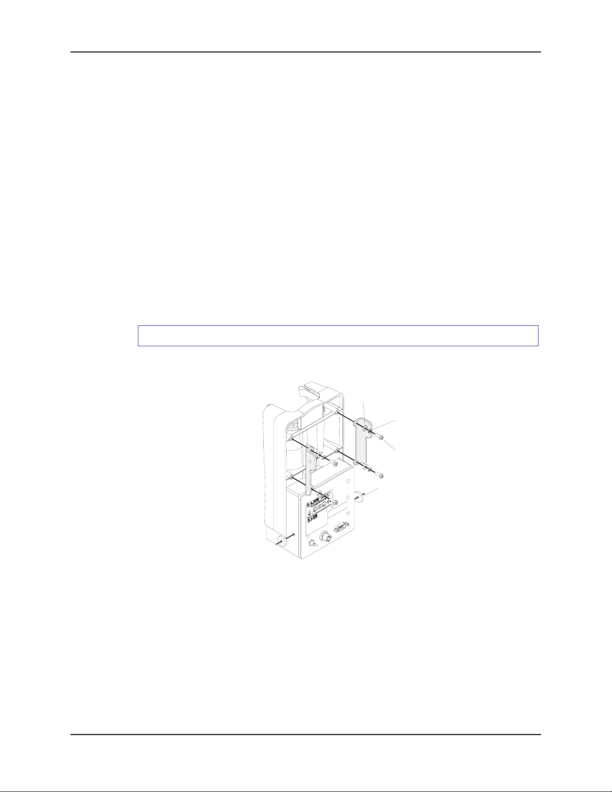
Cradle With Power/Communications Module
Equipment Needed: Torque wrench capable of torquing to 8±1 in/lb (.90±.11 N/m) .
Flat Washer
Lock Washe
Pan Head
Screw
Spacer
1. If the mobile device is in the storage cradle, remove it from the cradle and place in a safe
location.
2. Turn the Power Module off and remove all cables from the Power Module.
3. Place the cradle face down on a flat surface.
4. Put the Left and Right Brackets on the cradle, aligning the screw holes in the cradle with the
screw holes in the brackets.
5. Insert a Flat Washer, Lock Washer and Pan Head Screw into each hole.
6. Torque the Pan Head Screws to 8±1 in/lb (.90±.11 N/m).
MX1 Cradle Reference Guide E-EQ-MX1DKRG-B
Page 39
Putting it all Together 31
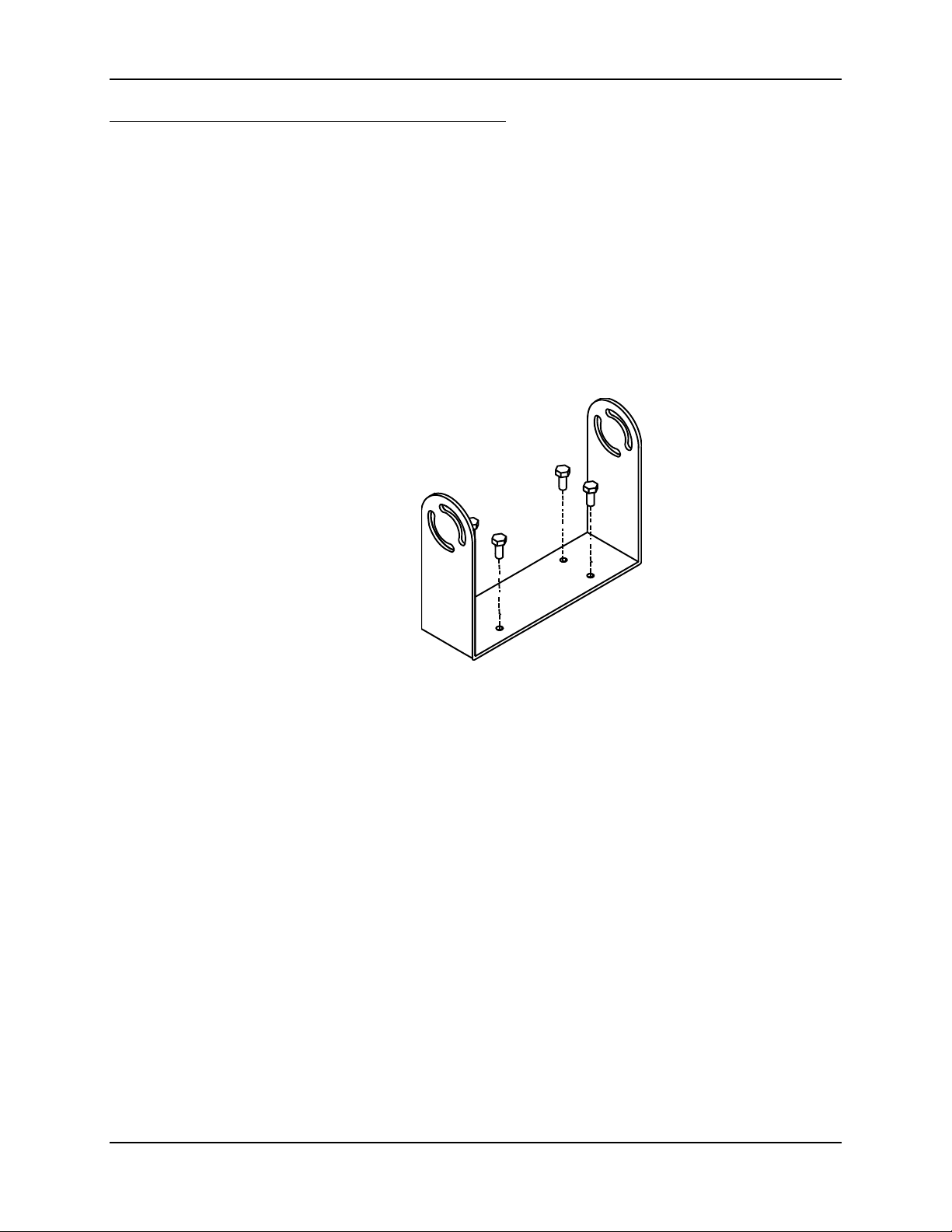
Step 2 - Mount Bottom Mounting Bracket to Vehicle
The vehicle mounted cradle should be mounted in an area in the vehicle where it:
• Does not obstruct the vehicle operator's vision or safe vehicle operation.
• Will be protected from rain or inclement weather.
• Will be protected from extremely high concentrations of dust or wind-blown debris.
• Can be easily accessed by a driver seated in the driver's seat.
Note: Install the Bottom Mounting Bracket to the vehicle before attaching the cradle.
Attach Bracket to Vehicle
There must be at least 8” clearance at the back of the bracket for the mobile device’s trigger
handle. Position the bracket to allow access to the switches and ports on the back of the Power
Module, if installed.
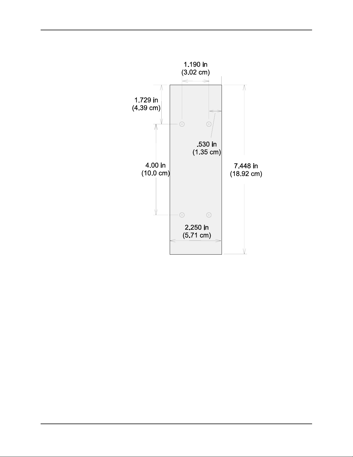
Using the mounting dimensions on the following diagram to mount the bottom mounting bracket
to the vehicle, using ¼” bolts (not supplied by LXE).
E-EQ-MX1DKRG-B MX1 Cradle Reference Guide
Page 40
32 Putting it all Together
Mounting Dimensions, Vehicle Mount (Not to Scale)
Use the dimensions on this diagram to place the vehicle mount bracket.
MX1 Cradle Reference Guide E-EQ-MX1DKRG-B
Page 41
Putting it all Together 33
)
)
Step 3 - Prepare the Cradle Mounting Assembly
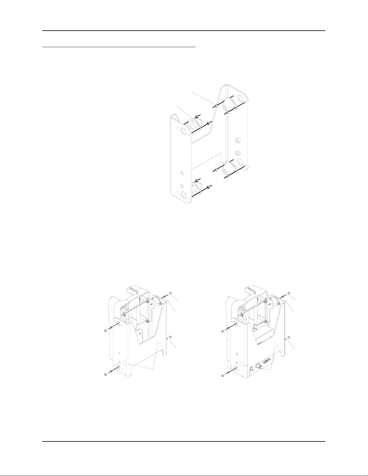
Equipment Needed: Torque wrench capable of torquing to 5±1 in/lb (.56±.11 N/m) and 15±1 in/lb
(1.69±.11 N/m).
Nut, Hex 4-40 Keps
Isolator
Attach Isolators to Upper Mounting Bracket
1. Place an isolator over an upper mounting bracket opening. Align the pins on the side of
the opening with the two small holes in the isolator.
2. Place a hex nut over each pin and tighten, torquing to 5±1 in/lb (.56±.11 N/m).
Now you are ready to attach the Upper Mounting Bracket to the cradle assembly.
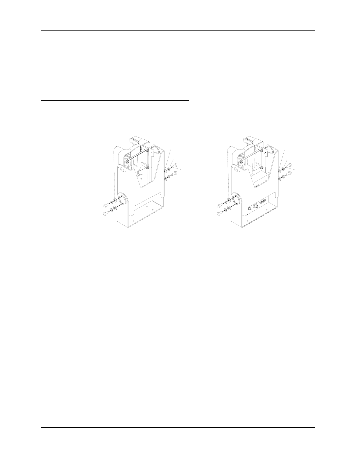
Assemble Upper and Lower Connectors
Pan Head
Spacers
inside
(8-32 x 1/2
Lock
Washer
Pan Head
(8-32 x 3/4)
Screw
Screw
Spacers
inside
(8-32 x 1/2
Lock
Washer
Pan Head
(8-32 x 3/4)
Without Power Module With Power Module
Pan Head
Screw
Screw
Connect Upper Bracket to Cradle Assembly
1. Put the aluminum spacers between the lower isolators and the Power Module (or Passive
Bracket).
E-EQ-MX1DKRG-B MX1 Cradle Reference Guide
Page 42
34 Putting it all Together
t
t
2. Insert lock washer and 8-32 x ¾ pan head screw in upper and lower openings, being sure to
thread the screw through the lock washer, isolator and spacer (spacer in lower opening).
3. Loosely tighten each pan head screw as it is inserted. Important: Do not torque screws
until all screws are threaded in place.
4. Torque all four pan head screws to 15±1 in/lb (1.69±.11 N/m).
Now you are ready to connect the assembled cradle to the vehicle.
Step 4 - Connect Cradle to Vehicle Bracket
Equipment Needed: Torque wrench capable of torquing to 50±5 in/lb (5.65±.56 N/m).
Flat
Washer
Lock
Washer
Bol
Flat
Washer
Lock
Washer
Bol
Cradle without Power Module Cradle with Power Module
Connect Cradle to Vehicle Mounting Bracket
1. Insert mounting bolts (place washer first) through the curved apertures in the Bottom Bracket
and into the screws holes in the Upper Bracket.
2. Securely fasten the hex bolts by torquing the bolts to 50±5 in/lb (5.65±.56 N/m).
3. Loosen the hex bolts on both sides to adjust the viewing angle of the mounted cradle then
tighten the hex bolts.
4. Test the torque on the bolts frequently during operation and re-tighten if necessary to
50±5 in/lb (5.65±.56 N/m).
5. Connect all cables to the Power Module, if installed.
6. The vehicle mounted cradle is now ready for use.
MX1 Cradle Reference Guide E-EQ-MX1DKRG-B
Page 43
Power Supplies and Cable Connections 35
Power Supplies and Cable Connections
LXE computers require a continuous source of relatively noise-free DC power. If this requirement
is not satisfied, data in the LXE computer may be lost. The cradle can be powered by any one of
the following three standard electrical supply configurations:
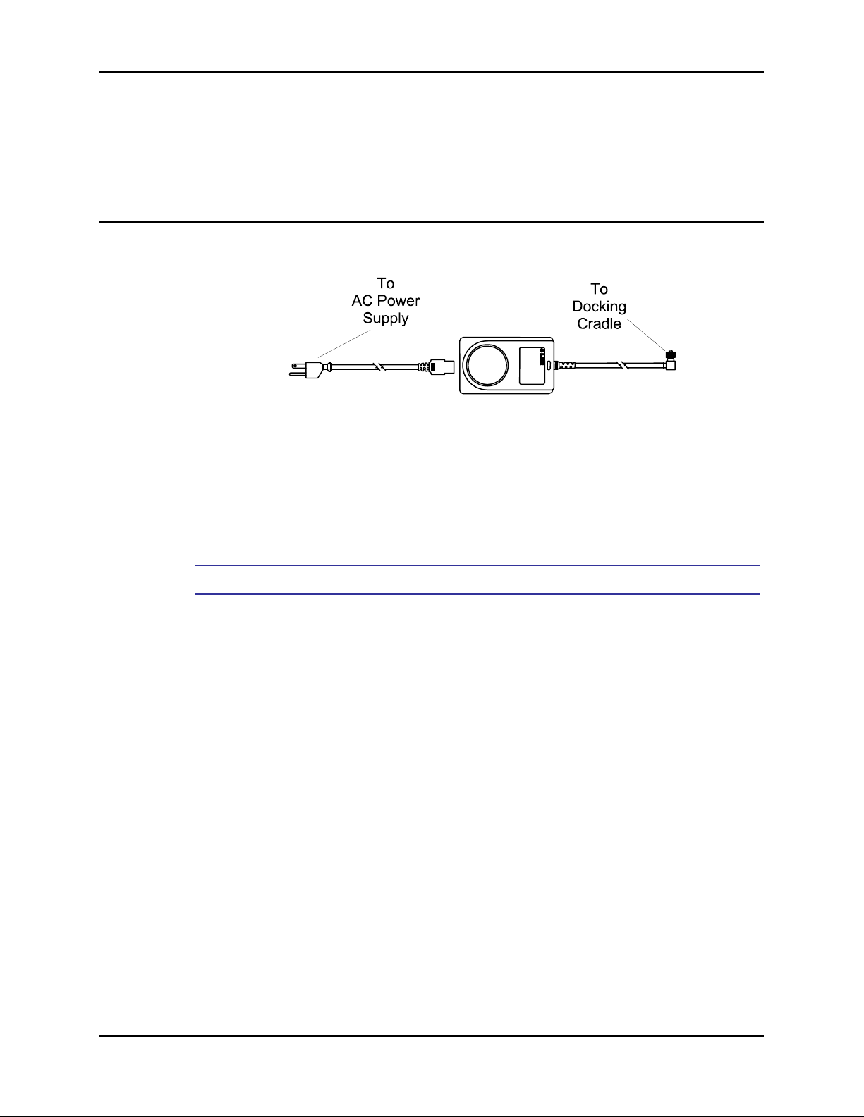
AC Power Supply
Figure 2-2 120/240VAC Input to DC Power Supply
The external AC supply may be connected to either a 120V, 60Hz supply or, outside North
America, to a 230V, 50Hz supply, using the appropriate detachable cordset. In all cases, connect
the external AC supply to a properly grounded source of supply provided with maximum 15 Amp
overcurrent protection (10 Amp for 230V circuits).
The figure shown above must provide Inherently Limited 12VDC NEC Class 2 Output (or LPS
Output as Defined By UL 1950), with Minimum Output Ratings of 1.7A and 14 Watts.
How To
1. If the mobile device is in the storage cradle, it can be either On or Off during this process.
2. Turn the Docking Cradle off.
3. Connect the detachable cordset provided by LXE to the external AC supply (IEC 320
connector).
4. Plug cordset into appropriate, grounded, electrical supply receptacle.
5. Connect the Molex connector end to the cradle by aligning the connector pins to the power
connector; push down on the Molex connector and twist it to fasten securely.
6. Turn the cradle on.
7. The Power LED and Cradle Power LED illuminate.
8. Battery Charging LED illuminates (steady or blinking).
E-EQ-MX1DKRG-B MX1 Cradle Reference Guide
Page 44
36 Power Supplies and Cable Connections
Vehicle Power Connections
Caution:
Warning:
Foreign Language Translations
The Vehicle Cable Connection sections of this chapter have been translated into the following
languages:
• French
• German
• Italian
• Portuguese
• Spanish
• Swedish
Please refer to the following documents, available on the LXE website in the Archived section, for
the translated text:
Electrical supply connections should only be performed by a qualified
technician or electrician.
Risk of ignition or explosion. Explosive gas mixture may be vented from
battery. Work only in well ventilated area. Avoid creating arcs and sparks
at battery terminals.
Vehicle “2330 Docking Cradle Vehicle Mounting Bracket” Installation Instruction Sheet
(DocID 2330A142INSTVEH).
Table “2330 Docking Cradle Table Mounting Bracket” Installation Instruction Sheet
(DocID 2330A140INSTTBL).
Wall “2330 Docking Cradle Wall Mounting Bracket” Installation Instruction Sheet
(DocID 2330A141INSTWALL).
MX1 Cradle Reference Guide E-EQ-MX1DKRG-B
Page 45
Power Supplies and Cable Connections 37
Vehicle 24/60VDC Input Cable Connection
Caution
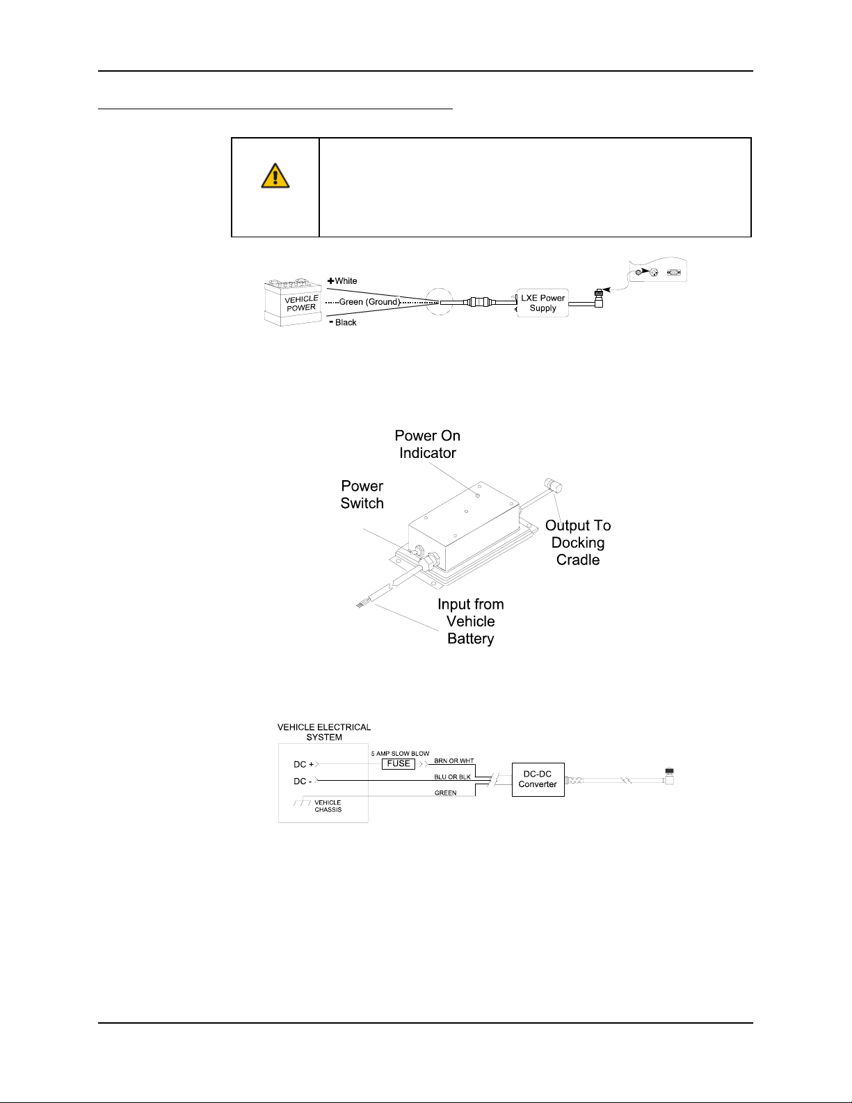
Figure 2-3 24/60 VDC Input to Power Supply Providing 12VDC Output (Shown
For proper and safe installation, the input power cable must be connected
to a fused circuit on the vehicle. This fused circuit requires a 5 Amp
maximum time delay (slow blow) fuse. If the supply connection is made
directly to the battery, the fuse should be installed in the positive lead
within 5 inches of the battery positive (+) terminal.
Without Fuse)
Figure 2-4 Vehicle Power Supply, 24 - 60VDC (Fuse Not Shown)
Figure 2-5 Connecting the Power Supply to the Vehicle
E-EQ-MX1DKRG-B MX1 Cradle Reference Guide
Page 46

38 Power Supplies and Cable Connections
How To
1. If the mobile device is in the storage cradle, it can be either On or Off during this process.
2. Turn the Docking Cradle off. Turn the Power Supply toggle switch to the Off position.
3. While observing the fuse requirements specified above, connect the power cable as close as
possible to the actual battery terminals of the vehicle. When available, always connect to
unswitched terminals in vehicle fuse panel, after providing proper fusing.
IMPORTANT:
For uninterrupted power, electrical supply connections should not be made at any point
after the ignition switch of the vehicle.
4. Route the cable the shortest way possible. The input cable from the connection to the battery
is rated for a maximum temperature of 60°C (140°F). When routing this cable it should be
protected from physical damage and from surfaces which might exceed this temperature.
Additionally do not expose the cable to chemicals or oil that may cause the wiring insulation
to deteriorate.
Note: If the vehicle is equipped with a panel containing Silicon Controller Rectifiers
(SCR's), avoid routing the power cable in close proximity to these devices.
Always route the cable so that it does not interfere with the user's safe operation and
maintenance of the vehicle. Use proper electrical and mechanical fastening means for
terminating the cable. Properly sized "crimp" type electrical terminals are an accepted method
of termination.
Wiring color codes for LXE supplied DC input power cabling:
Vehicle Supply Wire Color
+12VDC (DC +) Brown or White
Return (DC -) Blue or Black
Vehicle Chassis (GND) Green
Figure 2-6 Vehicle Connection Wiring Color Codes
Note: The input power cord for the DC-DC Power Supply uses white, black and green
wires. Some LXE products have DC input power cords with brown, blue and green
wires. The previous table shows the correct electrical connection for either type of
cable.
5. Provide mechanical support for the cable by securing it to the vehicle structure at
approximately one foot intervals, taking care not to overtighten and pinch conductors or
penetrate outer cable jacket.
6. Connect the Power Supply to the cradle by aligning the Molex connector pins to the power
connector; push down on the Molex connector and twist it to fasten securely.
7. Turn the Power Supply on. The ON LED on the Power Supply illuminates when it is
receiving power from the vehicle.
8. Turn the Docking Cradle on. The Docking Power LED and Cradle Power LED illuminate.
9. The Battery Charging LED illuminates (steady or blinking) when the mobile device is in the
cradle.
MX1 Cradle Reference Guide E-EQ-MX1DKRG-B
Page 47
Power Supplies and Cable Connections 39
Vehicle 8-18VDC Direct Connection
Caution
For proper and safe installation, the input power cable must be
connected to a fused circuit on the vehicle. This fused circuit requires a 5
Amp maximum time delay (slow blow) fuse. If the supply connection is
made directly to the battery, the fuse should be installed in the positive
lead within 5 inches of the battery positive (+) terminal.
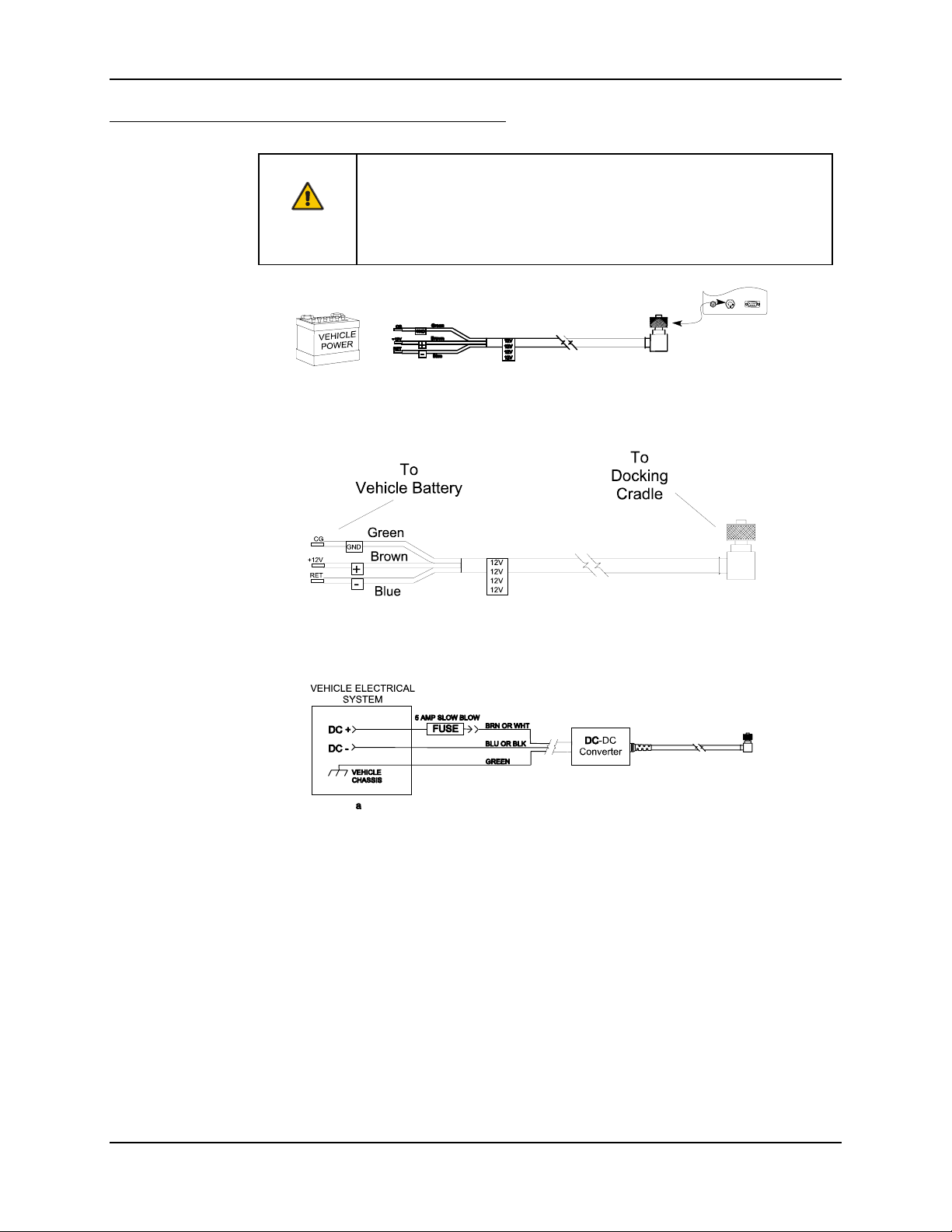
Figure 2-7 8 - 18 VDC Direct Vehicle Connection (Shown Without Fuse)
Figure 2-8 Direct Vehicle Power Connection (Fuse Not Shown)
Figure 2-9 Connecting the Power Supply to the Vehicle
E-EQ-MX1DKRG-B MX1 Cradle Reference Guide
Page 48

40 Power Supplies and Cable Connections
How To
1. If the mobile device is in the storage cradle, it can be either On or Off during this process.
2. While observing the fuse requirements specified above, connect the power cable as close as
possible to the actual battery terminals of the vehicle. When available, always connect to
unswitched terminals in vehicle fuse panel, after providing proper fusing.
IMPORTANT:
For uninterrupted power, electrical supply connections should not be made at any point
after the ignition switch of the vehicle.
3. Route the cable the shortest way possible. The input cable from the connection to the battery
is rated for a maximum temperature of 60°C (140°F). When routing this cable it should be
protected from physical damage and from surfaces which might exceed this temperature.
Additionally do not expose the cable to chemicals or oil that may cause the wiring insulation
to deteriorate.
Note: If the vehicle is equipped with a panel containing Silicon Controller Rectifiers
(SCR's), avoid routing the power cable in close proximity to these devices.
Always route the cable so that it does not interfere with the operator's safe operation and
maintenance of the vehicle. Use proper electrical and mechanical fastening means for
terminating the cable. Properly sized "crimp" type electrical terminals are an accepted method
of termination.
Wiring color codes for LXE supplied DC input power cabling:
Vehicle Supply Wire Color
+12VDC (DC +) Brown or White
Return (DC -) Blue or Black
Vehicle Chassis (GND) Green
Figure 2-10 Vehicle Connection Wiring Color Codes
Note: The input power cord for the DC-DC Power Supply uses white, black and green
wires. Some LXE products have DC input power cords with brown, blue and green
wires. The previous table shows the correct electrical connection for either type of
cable.
4. Provide mechanical support for the cable by securing it to the vehicle structure at
approximately one foot intervals, taking care not to overtighten and pinch conductors or
penetrate outer cable jacket.
5. Connect the cable to the Docking Cradle by aligning the Molex connector pins to the power
connector; push down on the Molex connector and twist it to fasten securely.
6. Turn the cradle on.
7. The Docking Power LED and Cradle Power LED illuminate when the docking cradle is
receiving power from the vehicle’s power source (battery).
8. The Battery Charging LED illuminates (steady or blinking) when a mobile device is in the
cradle.
MX1 Cradle Reference Guide E-EQ-MX1DKRG-B
Page 49
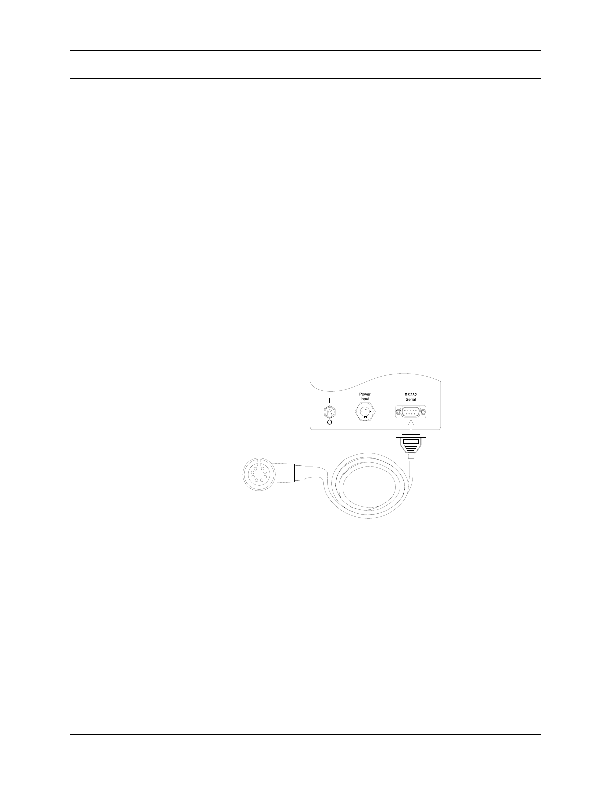
Power Supplies and Cable Connections 41
Connect RS232 Cable
Connect the RS232 cable to the Power Module to download data from the mobile device to a
printer or another computer. A data transfer program is required before data can be exchanged
between the mobile device and a desktop computer.
Note: After the cables are installed, the mobile device (client) and, if applicable, the other
computer (host) must be powered on and running the data transfer program before data
can be transferred.
Connect Using 25-Pin or 9-Pin Printer/PC Cable
1. Turn the mobile device and the cradle Off.
2. Connect the 9-pin connector end to the RS-232 port on the back of the Docking Cradle and
fasten securely.
3. Connect the other connector end to the receiving computer or printer’s serial port and fasten
securely.
4. Turn the Docking Cradle on then turn the mobile device on.
Note: A null modem and/or gender changer may be required to connect the 25-pin connector
end to computer or printer.
Connect Using DIN Cable
1. Turn the mobile device and the cradle Off.
2. Connect the 9-pin connector end to the Docking Cradle and fasten securely.
3. Connect the DIN connector end to the receiving printer’s DIN port by fitting the pins over the
connector. Push and twist the DIN connector head to fasten the connection.
4. Turn the Docking Cradle on then turn the mobile device on.
Figure 2-11 D9 to DIN Printer Cable
E-EQ-MX1DKRG-B MX1 Cradle Reference Guide
Page 50

42 Power Supplies and Cable Connections
Docking Cradle End Molex Connector Location
After completing external power connection process (and RS232 cable connection, if any),
connect the molex connector to the docking cradle.
Figure 2-12 Docking Cradle End Molex Connector
The docking cradle is ready to be turned on.
ON Toggle switch is UP (I).
OFF Toggle switch is DOWN (O).
MX1 Cradle Reference Guide E-EQ-MX1DKRG-B
Page 51
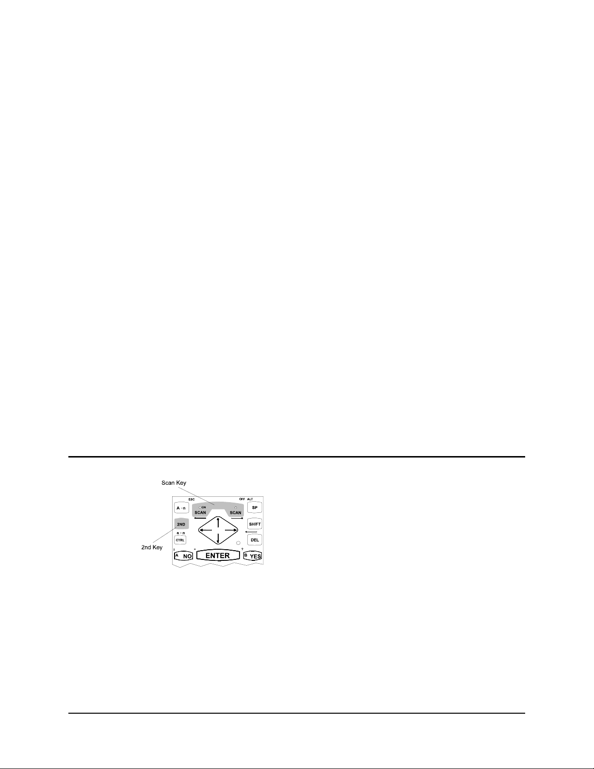
Introduction
Chapter 3 Using The Docking Cradle
The mobile device can be inserted in the cradle with or without:
• the hand trigger grip
• a handstrap
• a spare battery.
Note: The mobile device may be turned On or Off while inserting or removing it from the
cradle.
The mobile device must have an installed battery pack before battery charging will proceed.
Before battery charging can begin, the Docking Cradle must have a Power/Charging and
Communications Module. It must also be connected to an external power source.
The Docking Power LED and Cradle Power LED must be illuminated before:
• mobile device battery charging begins.
• IrDA port data transmission to printer begins.
• RS232 port data transmission begins.
Prepare Mobile Device For Docking Cradle
The main battery pack will begin charging as soon as the mobile device is placed in the docking
cradle regardless of the mobile device’s On/Off status.
Turn off the 2330
The 2330 is turned off by pressing the 2nd key then
pressing the Scan key.
Figure 3-1 Turn 2330 Off
E-EQ-MX1DKRG-B MX1 Cradle Reference Guide
Page 52
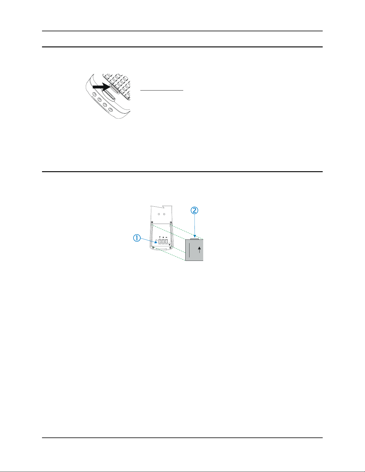
44 Prepare Mobile Device For Docking Cradle
Turn off the 2335 and MX1
Hold the Power button down. The unit will emit three short beeps
and one long beep. After the long beep the mobile device will
power down. The Power button and the display will turn off.
Troubleshooting
The 2335 or MX1 will not turn off – force a Power Off by holding
the Power key down for 15 seconds and the mobile device will
power off. Locate and correct the problem before powering the
mobile device back on – e.g. IRQ conflict, very low battery power,
radio conflict, unexpected software application result, etc.
Figure 3-2 Location of the Power Button on the 2335 and MX1
Note: Quickly tapping or releasing the Power button prior to the one long beep signal will
place the mobile device in Suspend mode (if Suspend is enabled).
Insert Main Battery Pack in Mobile Device
Note: Mobile devices must be turned OFF before the Main Battery Pack is inserted.
1. Battery Contacts
2. Battery Pack Tab
Figure 3-3 Insert Battery And Close Cover
1. If the mobile device is powered on, save any work, and close running programs.
2. Turn the unit off.
3. Open the battery access panel or cover and remove the battery.
4. Insert an appropriate fully charged battery, aligning the positive and negative contacts on the
battery with the metal contacts in the unit.
5. Close the battery access panel or cover.
6. Turn the unit on.
Place the used battery in the appropriate battery charger/analyzer.
MX1 Cradle Reference Guide E-EQ-MX1DKRG-B
Page 53
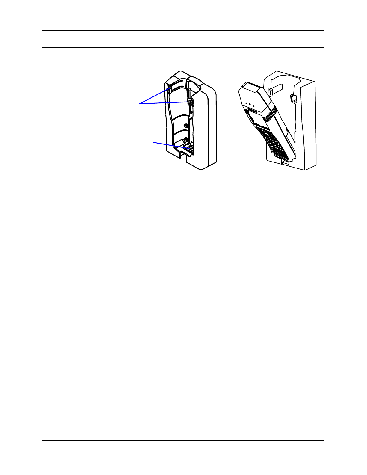
Prepare Mobile Device For Docking Cradle 45
Insert Mobile Device in Powered Cradle
The device is held in the cradle with the display and keyboard facing outwards.
Spring
Clip
Power/Battery
Contacts
(when PCM
installed
In cradle)
Figure 3-4 Spring Clips and Power/Battery
1. Push the mobile device (with or without the hand trigger-grip) into the cradle “tail first”.
2. Gently push the mobile device down past the spring clips until both click into place over the
top of the mobile device.
The mobile device can be removed or inserted with one hand. If the powered cradle is a desktop
unit, hold the desktop unit with one hand while removing the mobile device with the other. The
desktop unit may move unless it is held stationary while the mobile device is removed or inserted.
Contacts
Figure 3-5 Insert Device in
Cradle
E-EQ-MX1DKRG-B MX1 Cradle Reference Guide
Page 54

46 Data Transfer Methods
Data Transfer Methods
Note: The docking cradle must have a Power Charging and Communications Module installed
before data transfer can begin.
The InfraRed (IR) to RS232 interface provides conversion of infrared data from the IR port into
RS232 serial data to be output to serial devices (printer or computer). This allows the mobile
device to communicate with non-IR devices.
No software is present or required in the docking cradle.
Communication software is required for the client (mobile device) and the host (computer).
See the “2330 Reference Guide” (DocID 2330A137REFGD) in the
Archive section on the LXE Website for additional file transfer
information.
Cables
A null modem cable may be required to connect the docking cradle and a desktop printer. Please
refer to the printer manufacturer’s instructions for further information.
LXE offers three printer and/or PC cables:
• D9 to D25 Printer/PC cable,
• D9 to D9 PC cable
• D9 to DIN Renegade printer cable
Make sure you have the appropriate cable for the equipment to be used for data transmission.
Note: IrDA data transfer to an IR printer does not require cabling.
MX1 Cradle Reference Guide E-EQ-MX1DKRG-B
Page 55

Data Transfer Methods 47
RS232 Serial Port on the Docking Cradle
Note: This port is located on the cradle, on the Power Charging and Communications Module.
Either hardware (RTS/CTS) or software (XON/XOFF) can be used to communicate over the serial
port. The port is configured as a 9-pin DCE port with the following connector pinouts:
Figure 3-6 Male 9-Pin Connector on the PCM
Note: During hardware handshake, CTS and DSR will be in the same state as RTS and DTR,
respectively.
Signal Name Pin No.
TD 3
RD 2
CTS 8
RTS 7
DTR 4
DSR 6
GND 5
Figure 3-7 RS232 Serial Port Pinout on the PCM
A null modem cable may be required to connect the docking cradle and a
desktop printer. Please refer to the printer manufacturer’s instructions for
further information.
E-EQ-MX1DKRG-B MX1 Cradle Reference Guide
Page 56

48 Data Transfer Methods
Sending Data to an External Computer
The client (mobile device), host computer and docking cradle must be powered on during this
process.
Note: The client and the external computer must be running the same communication software.
1. If necessary, disable (REM out) the IrDA protocol driver (IRDACOM.SYS) in the
CONFIG.SYS file.
2. Connect the appropriate serial cable to the cradle’s PCM serial port and the serial port on the
external computer.
3. Begin running the communications software on the external computer. Set up the software to
receive data using the computer’s RS232 port that is connected to the Docking Cradle.
4. Begin running the communications software on the mobile device. Set up the software to send
data using the mobile device’s COM1 port.
5. Hint: Clear both screen displays to more easily view file transmission progress.
6. Place the mobile device in the Docking Cradle, seating the IrDA window firmly over the
IrDA window in the cradle. The IrDA port is now the COM1 port. During transmission the
data signal will exit the mobile device’s IrDA port, be captured by the IR port on the cradle
and be transmitted through the RS232 port on the cradle to the external computer.
7. Press the appropriate keys on the mobile device to transmit the file to the external computer.
During transmission, the IR Status LED will blink. When transmission is complete the IR Status
LED will turn off.
MX1 Cradle Reference Guide E-EQ-MX1DKRG-B
Page 57

Data Transfer Methods 49
Receiving Data from an External Computer
The mobile device, external computer and docking cradle must be powered on during this process.
Note: The mobile device and the external computer must be running the same communication
software.
1. If necessary, disable (REM out) the IrDA protocol driver (IRDACOM.SYS) in the
CONFIG.SYS file.
2. Connect the appropriate serial cable to the cradle’s serial port and the serial port on the
external computer.
3. Begin running the communications software on the external computer. Set up the software to
send data using the computer’s RS232 port that is connected to the Docking Cradle.
1
4. Begin running the communications software
receive data using the mobile device’s COM1 port.
5. Hint: Clear both screen displays to more easily view file transmission progress.
6. Place the mobile device in the Docking Cradle, seating the IrDA window firmly over the
IrDA window in the cradle. The IrDA port is now the COM1 port. During transmission the
data signal arrives at the cradle’s RS232 port, is transferred to the the IR port and transmitted
to the mobile device through it’s IrDA port.
on the mobile device. Set up the software to
7. Press the appropriate keys on the external computer to transmit the file to the mobile device.
During transmission, the IR Status LED will blink. When transmission is complete the IR Status
LED will turn off.
1
The mobile device hardware provides half duplex communications only, therefore zmodem
transfer protocol cannot be utilized. LXE recommends using ASCII text or ymodem protocol.
E-EQ-MX1DKRG-B MX1 Cradle Reference Guide
Page 58

50 Data Transfer Methods
Serial File Transfer Utility using ROM-DOS Commands
Note: REMSERV and REMDISK are included in the Datalight ROM-DOS file load for serial
file transfers.
Note: Devices with MS-DOS should use INTERLNK and INTERSVR for serial file transfer.
A null modem cable must be used to connect the two computers. Both computers must have both
REMSERV and REMDISK set to the same settings. REMSERV is run on the host (which is
usually the mobile computer). REMDISK is run on the client (which is usually a desktop or laptop
PC).
Using this utility you can move files from one computer to the other over the serial line using the
DOS Copy or Xcopy commands.
REMSERV
REMSERV.EXE d: [/T] [/H] [/Bxxxx][+|-] [/COMn] [/IRQn]
/Bxxxx Set the baud rate. Choose from 300, 1200, 2400, 19200, 38400, 57600, 115. A ‘+’
after the BAUD specifies ‘packet’ style transfers. By default, packet transfers will
be used for all baud rates higher than 9600. Use ‘-’ after the BAUD to force
polling operation under Microsoft Windows 95. Both sides must agree on using
either ‘+’ or ‘-’.
/COMn Set the communications port. Choose 1, 2, 3 or 4.
/IRQn Set the IRQ for the communications port. choose 3-15.
/S Silent (no output).
/Tnnn Set the timeout in seconds. Choose 2-3640, 15 seconds is not unusual for FLASH
drives.
/H Use Hardware Handshaking for flow control.
Example:
REMSERV D: /B38400- /COM2 /T10
Default:
/B115+ /COM1 /T2
MX1 Cradle Reference Guide E-EQ-MX1DKRG-B
Page 59

Data Transfer Methods 51
REMDISK
REMDISK [/?] [/U] [/T] [/H] [/Bxxxx][+|-] [/COMn] [/IRQn]
/Bxxxx Set the baud rate. Choose from 300, 1200, 2400, 19200, 38400, 57600, 115. A ‘+’
after the BAUD specifies ‘packet’ style transfers. By default, packet transfers will
be used for all baud rates higher than 9600. Use ‘-’ after the BAUD if REMSERV
is running under Microsoft Windows 95. Both sides must agree on using either ‘+’
or ‘-’.
/COMn Set the communications port. Choose 1, 2, 3 or 4.
/IRQn Set the IRQ for the communications port. Choose 3-15.
/Tnnn Set the timeout in seconds. Choose 3-3640, 15 seconds is not unusual for FLASH
drives.
/H Use Hardware Handshaking for flow control.
/U Unload REMDISK from memory.
Examples:
(in CONFIG.SYS) DEVICE=REMDISK.EXE /T15
(in AUTOEXEC.BAT) REMDISK /B9600 /COM2 /T10
Default:
/B115K+ /COM1 /T3
E-EQ-MX1DKRG-B MX1 Cradle Reference Guide
Page 60

52 Data Transfer Methods
Serial File Transfer using MS-DOS Commands
Note: LXE replaced Microsoft MS-DOS 6.22 with Datalight ROM-DOS 6.22 in March, 2001
on LXE DOS devices manufactured after that date. This information is placed here for
backward compatibility for the 2330 running MS-DOS.
Refer to commercially available MS-DOS user guides for more information on
the INTERLNK and INTERSVR commands.
Transferring Files Using MS-DOS INTERLNK / INTERSVR
Requirements
• An IBM compatible PC or laptop with:
• MS-DOS version 3 or later
• one serial port (minimum)
• one floppy drive (minimum).
• The mobile device with one available serial port and the MS-DOS program INTERSVR
loaded in the DOS directory.
• One 7-wire null modem serial cable for a serial connection.
Procedure
1. Using the 7 wire null modem cable, connect the PC/Laptop to the mobile device.
2. Using the PC/Laptop, make sure the INTERLNK.EXE file is located on the PC/Laptop’s hard
drive. (Typically located in the DOS directory.)
IMPORTANT If the INTERLNK.EXE file is not installed on the PC/Laptop go to step 3,
otherwise go to step 5.
3. If you are using a port other than COM1 on the PC/Laptop, make sure that the SHARE
program is not running on the PC/Laptop.
4. Using the mobile device, type the following at the MS-DOS prompt:
INTERSVR /RCOPY
INTERSVR must be running on the mobile device before it connects to the PC/Laptop. The
remote installation screen should appear, follow the instructions that appear on the screen.
5. Using the PC/Laptop, type the following at the MS-DOS prompt:
COPY C:\CONFIG.SYS C:\CONFIG.OLD
This will create a backup of the CONFIG.SYS file.
6. Using the PC/Laptop, type the following at the MS-DOS prompt:
EDIT C:\CONFIG.SYS
This will allow you to edit the CONFIG.SYS file. If EDIT is not installed or you prefer not to
use it, you may use any text editor to edit the CONFIG.SYS file.
MX1 Cradle Reference Guide E-EQ-MX1DKRG-B
Page 61
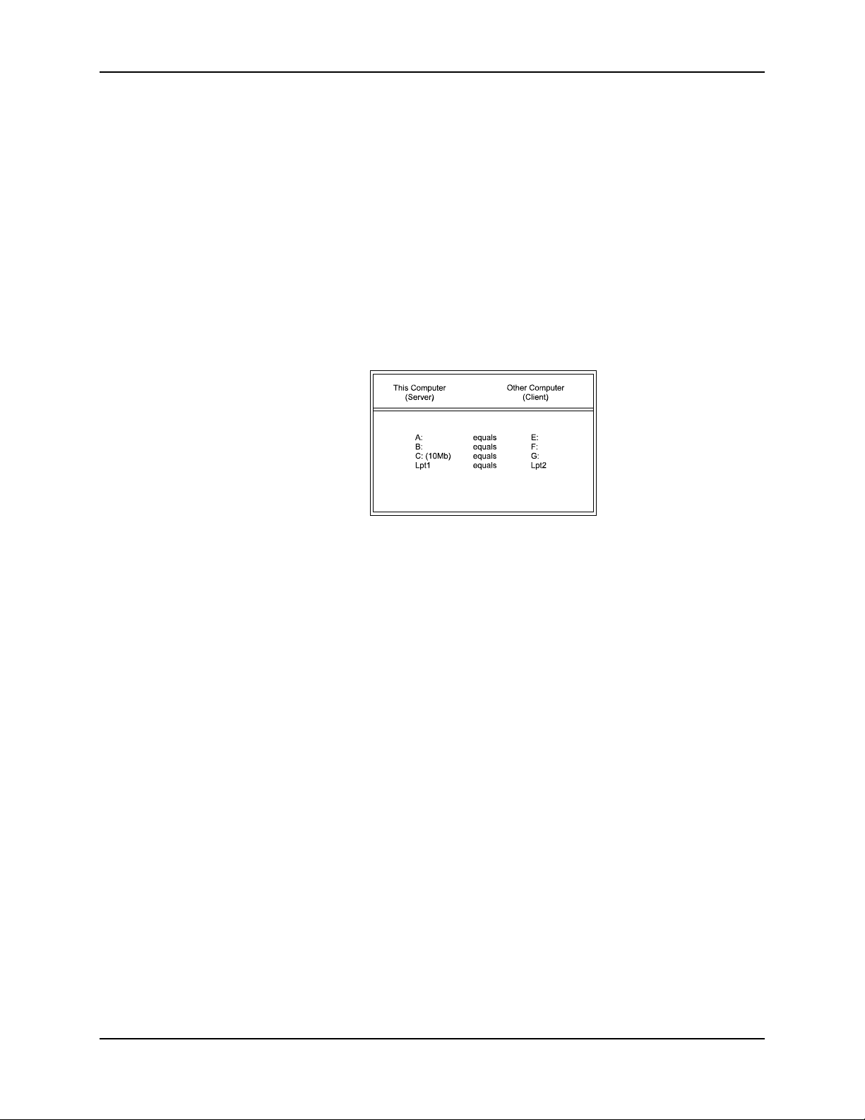
Data Transfer Methods 53
7. Add a DEVICE command to the end of the CONFIG.SYS file that specifies the location of
the INTERLNK.EXE file. The following example specifies an INTERLNK file that is located
in the DOS directory on the C: drive.
Example: DEVICE=C:\DOS\INTERLNK.EXE
8. Save the changes to your CONFIG.SYS file and exit the text editor. (Typically pressing
<ALT> + <F>, then <X> will save and exit. If using a later version of MS-DOS EDIT, you
will be asked to verify that the changes should be saved. Press <Y> to save changes or <N>
to discard changes.)
9. Using the mobile device, type the following at the MS-DOS prompt:
INTERSVR
INTERLNK (now running on the PC/Laptop) should display information about the redirected
drives and printer ports on the mobile device’s screen. (See example below.)
10. Restart the PC/Laptop by pressing <CTRL> + <ALT> + <DEL>.
IMPORTANT INTERSVR must be running before starting INTERLNK.
11. Locate the files to be transferred to the mobile device from the PC/Laptop. (Use the DOS DIR
and CD commands to locate files.)
12. Copy the specified files from the PC/Laptop to the mobile device. (Use the DOS COPY or
XCOPY commands to copy the specified files from the PC/Laptop.)
Example:
COPY C:\AUTOEXEC.BAT G:\AUTOEXEC.BAT
This example copies a single file (AUTOEXEC.BAT) from the root directory (\C) on the
PC/Laptop to the redirected C drive (\G) on the mobile device.
13. Break the server connection between the two computers by pressing <ALT> + <F4> on the
server keyboard (the mobile device).
E-EQ-MX1DKRG-B MX1 Cradle Reference Guide
Page 62
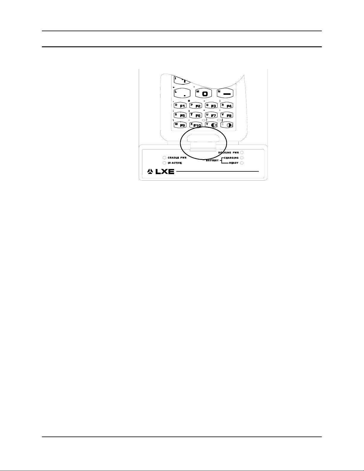
54 Data Transfer Methods
IR Port
Figure 3-8 PCM and IR Ports Line Up
The InfraRed (IR) port is located at the top, and at the front of the PCM. It is designed to receive
and transmit data with the IrDA port on the end of the mobile device. The two IR ports line up
directly with each other when the mobile device is secured in the Docking Cradle.
Additionally, the cradle allows “pass through” of the device’s infrared to an external IR device
(i.e. IrDA printer). The cradle will need to be rotated slightly backward to provide line-of-sight
IR.
The IR operating envelope has a distance range of 2 cm (.79 inches) to 1 meter (3.2 feet) with a
viewing angle of 30 degrees.
Note to Programmers
IR Port Transmitting Data Through RS-232 Port
When the mobile device’s IrDA port is initially opened to send (or when changing states), the
cradle’s RS-232 RXD (pin 2) and TXD (pin 3) pins are active. RXD should be ignored when
TXD is activated or the data transmitted may be immediately returned through the IR port by the
RXD pin. The data transfer direction is half-duplex only.
MX1 Cradle Reference Guide E-EQ-MX1DKRG-B
Page 63

Data Transfer Methods 55
Sending Data to a Printer With an IR Port
The mobile device, printer and docking cradle must be powered on during this process.
1. If necessary, enable the IrDA protocol driver (IRDACOM.SYS) in the CONFIG.SYS file.
2. Set up the mobile device to send the file over the COM1 communication port (which is now
the IrDA port).
3. Place the mobile device in the docking cradle.
4. Place the IR window on the IrDA compatible printer (e.g. O’Neil microFlash Printer) in front
of the mobile device’s IR window, with the device mounted in the docking cradle.
5. Locate the printer within 1 meter of the cradle and within a 30 degree operating angle of the
mobile device’s IR window. The docking cradle may need to be rotated backward to allow
proper line-of-sight for both IR windows.
6. Transmit the file from the mobile device to the printer, (e.g. O’Neil microFlash Printer).
During transmission, the IR Status LED on the cradle will blink. When transmission is complete
the IR Status LED will turn off.
Sending Data to a Printer Without an IR Port
A null modem cable may be required to connect the docking cradle and a
desktop printer. Please refer to the printer manufacturer’s instructions
for further information.
The mobile device, printer and docking cradle must be powered on during this process.
1. If necessary, disable (REM out) the IrDA protocol driver (IRDACOM.SYS) in the
CONFIG.SYS file.
2. Connect the appropriate serial cable to the cradle’s serial port and the printer.
2
3. Begin running the printer communications software
on the mobile device. Set up the
software to print using the mobile device’s COM1 port.
4. Hint: Clear the screen to more easily view file print progress.
5. Place the mobile device in the Docking Cradle, seating the IrDA window firmly over the
IrDA window in the cradle. The IrDA port is now the COM1 port. During transmission the
data signal will exit the device’s IrDA port, be captured by the IR port on the cradle and be
transmitted through the RS232 port to the printer, (e.g. O’Neil microFlash Printer).
6. Press the appropriate keys on the mobile device to transmit the file to the printer.
During transmission, the IR Status LED will blink. When transmission is complete the IR Status
LED will turn off.
2
The mobile device hardware provides half duplex communications only, therefore zmodem
transfer protocol cannot be utilized. LXE recommends using ASCII text or ymodem protocol.
E-EQ-MX1DKRG-B MX1 Cradle Reference Guide
Page 64

56 Data Transfer Methods
MX1 Cradle Reference Guide E-EQ-MX1DKRG-B
Page 65
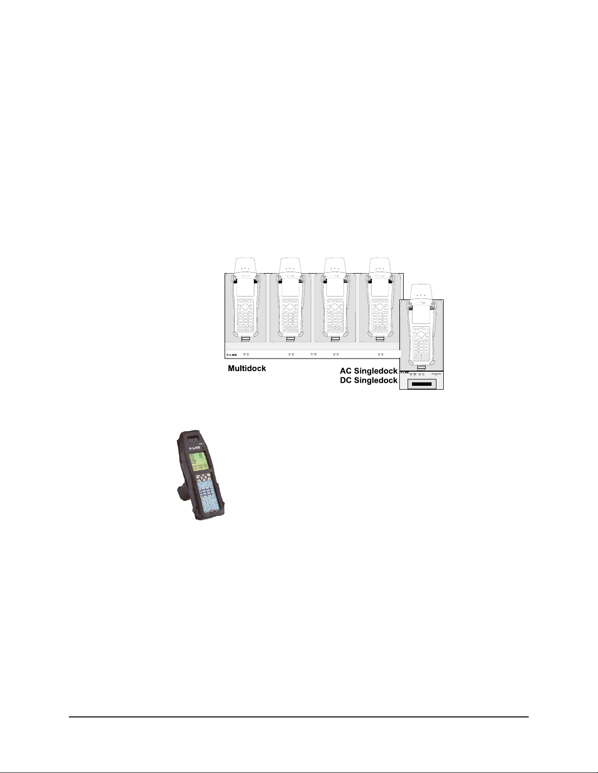
Introduction
Chapter 4 Multidock and AC/DC Singledocks
The MX1 Docking Cradle family includes an AC Singledock, a DC Singledock and a Multidock.
The AC Singledock and Multidock are designed for protected, indoor use while the DC
Singledock is mounted in a vehicle. All docks use a modular cradle designed to support and
protect a mobile device, specifically the LXE 2330, 2335 and MX1. The mobile devices can be
fully operational while in the cradle, including display, keypad, RF and IR operation.
Figure 4-1 Multidock and Singledocks
Attention:
The MX1 Intrinsically Safe device and battery pack
are NOT compatible with the Multidock and AC/DC
Singledocks and may cause damage to the MX1-IS
and battery pack if placed in an unauthorized MX1IS docking cradle/charger. The MX1-IS keypad is
bright blue in color.
MX1 I-Safe
Three different powered docking stations are available for the MX1, the 2335 and the 2330.
These docking stations charge the computer’s main battery in under seven hours. In addition, the
dock provides power to operate the computer while it is in the dock. The dock also maintains a
charged main battery with a trickle charge. Since both single docking stations are similar in
operation and only differ by the power source (AC or DC current), they are described together in
this chapter.
The LXE publication “2330 Multidock Reference Guide” is available on the LXE Manuals CD
and on the LXE website.
E-EQ-MX1DKRG-B MX1 Cradle Reference Guide
Page 66
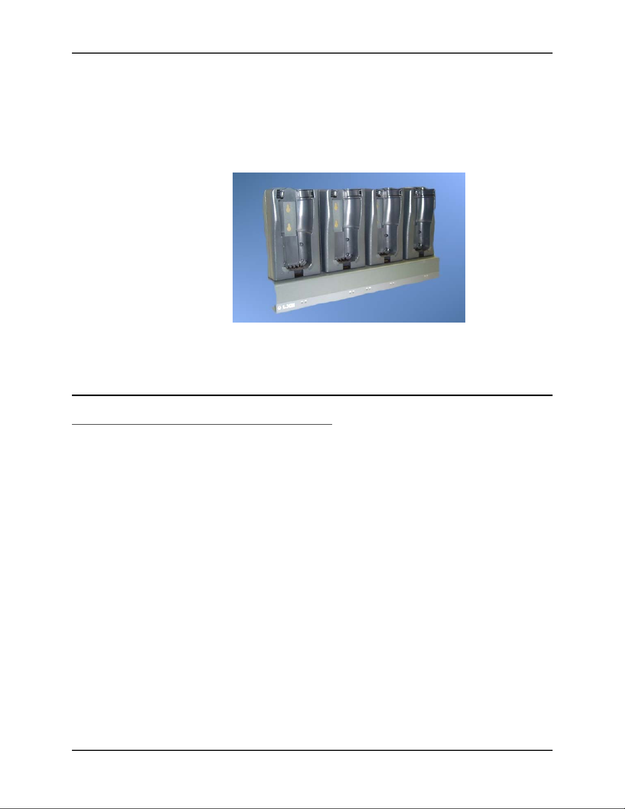
58 Multidock
Multidock
Note: An Upper Strap Bracket installation is a requirement prior to using any of the mobile
devices in a cradle. The bracket, as well as the spring clips on the cradle, helps to secure
the unit in the cradle. The handstrap is not a requirement.
Installation
Guidelines
Figure 4-2 Multidock
This dock holds four mobile devices. The status of the charging process is indicated by two lights
on the front of the multidock.
Follow these guidelines when setting up the Multidock system.
• Each Multidock and AC Singledock is always plugged into an AC outlet. If a modem is
included in the configuration, it too is plugged into an AC outlet.
• The host computer is always cabled to the first item in the configuration (a modem, an
RS232-RS485 converter or an AC Singledock).
• Multidocks that are chained together are cabled to each other with a 9-pin Multidock cable
(included with Multidock).
• Multidocks have an RS485 terminator installed at the end of the communications line.
9600 baud Singledocks have no terminator. 115k baud Singledocks require a Fast
terminator.
• For a direct PC connection to the host, the host PC is first cabled to a null modem cable,
then to a converter or an AC Singledock then to the Multidock.
Note: Only use the cables that came with each piece of equipment. Do not switch cables or
power supplies.
This section’s instructions are based on the assumption that your new equipment is pre-configured
and requires only peripheral installation (e.g. modem or printer) at least one mobile device and a
power source.
MX1 Cradle Reference Guide E-EQ-MX1DKRG-B
Page 67

Multidock 59
Procedure
1. Install Multidock(s) on a wall. If placed on a table, the Multidock may tip over when the
mobile device is inserted or removed from the cradle.
2. Cable each Multidock to the next making sure the last Multidock in the line contains the bus
terminator.
3. Cable the first Multidock in the line to the Singledock or Converter.
4. Cable the Singledock or converter to the host.
5. Insert mobile devices and spare batteries in Multidocks.
6. Connect AC power source to each Multidock.
7. Dock Power LEDs illuminate. Batteries begin to charge.
8. Turn the mobile devices on.
9. You are ready to begin host communication.
Features
The Multidock supports storage and charging of up to four hand held computers simultaneously.
There is no limit to the number of Multidocks and Singledocks that can be connected when their
only task is to secure and charge mobile devices and spare batteries.
Components
Multidocks and Singledocks can be daisy-chained together. A single PC communications port can
support up to 64 hand held computers. Up to 16 Multidocks can be daisy-chained to a single host
port. A four port digi-board installed in the host computer allows communications to both directconnect and remote handhelds via high speed modem.
The docks accommodate a high speed data communications link (up to 115 kb/second) to a host
computer. Remote handhelds in Singledocks communicate with the host via modem at 9600 baud
using a Hayes compatible modem and the RS-232 port.
Batch Operation
The Multidock and associated accessories are intended for use where a number of mobile devices
are used in batch operation. In these applications, the mobile devices are typically used for one
long shift and then left overnight to recharge. During the night the mobile devices can be stored,
batteries recharged and the data stored in the device from the current day’s work is downloaded to
the host. Data for the next day’s work is then uploaded into the targeted device. AC power is
constantly available to the devices in the Multidocks so communication can take place at any time
during the overnight hours.
Multidock and 9x9 Cable 2330A013MULTIDOCK
9600 Baud Terminator 2330A017RS485SLOW
115K Baud Terminator 2330A016RS485FAST
Converter 2330A015CONV232485
Null Modem Cable for Direct PC Connection 6200L200
AC Power Supply 1300A303PSACWW
E-EQ-MX1DKRG-B MX1 Cradle Reference Guide
Page 68
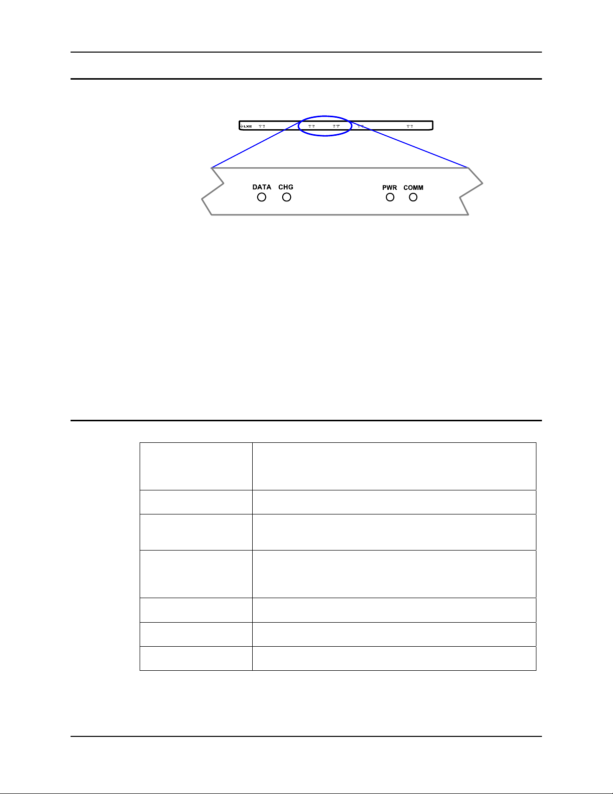
60 Multidock
Front Panel Indicators
Figure 4-3 Multidock Indicators
DATA When solid green or flashing green, the adjacent mobile device is sending data to
the host.
CHG When solid green, the battery in the mobile device is being charged. When dark, the
battery in the mobile device is fully charged and is receiving a trickle charge to
maintain the full charge.
PWR When green, the Multidock is receiving AC power.
COMM When solid green or flashing green, the host is sending data to all mobile device’s
Specifications
Communication
Interface
Baud Rate 9600 baud or 115k baud, Half Duplex selectable by terminator.
Indicators DATA and CHG per dock, PWR and COMM per Multidock, either
Battery Charging Multidock charges each battery within 7 hours and fully powers
Dimensions 23.0” wide x 12.5” high x 3.25” deep
Temperature 0°C to 50°C, 5% to 95% humidity
in the Multidock chain.
Two RS485 communication ports (9 pin D connector). Two ports
allow chaining of up to 16 Multidocks (64 terminals) to single host
port.
green or unlit.
device in addition to charging battery. Trickle charge maintains full
charge.
Power Input 110-250 VAC, 50/60 Hz
MX1 Cradle Reference Guide E-EQ-MX1DKRG-B
Page 69

Multidock 61
RS485 Converter
Host to client device and client device to host communications using the Multidock are through a
RS485 communications bus. The RS232 to RS485 converter facilitates connection to an RS232
host connector. The converter is powered by the Multidock and converts the signals of the two
RS485 buses to RS232 signal levels.
The converter has a 9 pin male connector that connects to the cable from the Multidock and a 25
pin male connector that connects to the cable from the host.
Pinout - RS485 Connector
Pin
1 Terminal Data Y
2 Baud Rate Control Input
3
4
5 Ground
6 Terminal Data Z
7 Host Comm B
8 Host Comm A
9 +5V Supplied
Terminator
Multidocks and Singledocks have a RS485 terminator installed at the end of the communications
line. 9600 baud Singledocks need no terminator. The terminators are available in two speeds:
115K baud and 9.6K baud.
The 115K baud terminator is used with host direct connections and the 9.6K baud terminator is
used with modem connection to the host.
Pinout - RS485 Terminator, 9.6K and 115K Baud
9.6K Baud
Pin Resistor Pin
7 120 Ohm 1/4W 8
1 120 Ohm 1/4W 6
115K Baud
Pin Resistor Pin
2 0 Ohm Jumper 9
7 120 Ohm 1/4W 8
1 120 Ohm 1/4W 6
E-EQ-MX1DKRG-B MX1 Cradle Reference Guide
Page 70
62 Multidock
RS485 Comm Port
Two RS485 (9 pin D style) connectors are located at each end of the Multidock. Each Multidock
can be daisychained to each other using a 9-pin to 9 pin cable from LXE.
Pinout - Null Modem Cable
Null 9 x 25
LXE Part No. 6200L200
DTE 9 Pin Female DTE 25 Pin Female
3 (TX) 3 (RX)
2 (RX) 2 (TX)
7 (RTS) 8 (DCD)
1 (DCD) 4 (RTS)
6, 8 (DSR, CTS) 20 (DTR)
4 (DTR) 5, 6 (CTS, DSR)
5 (GND) 7 (GND)
Null 25 x 25
LXE Part No. 6200L202
DTE 25 Pin Female DTE 25 Pin Female
1 (PROT GND) 1 (PROT GND)
2 (TX) 3 (RX)
3 (RX) 2 (TX)
4 (RTS) 8 (DCD)
8 (DCD) 4 (RTS)
5, 6 (CTS, DSR) 20 (DTR)
20 (DTR) 5, 6 (CTS, DSR)
7 (SIG GND) 7 (SIG GND)
Pinout - Straight Through Cable
Straight Through 9 x 25
LXE Part No. 9000A052CBL6D9D25
DTE 9 Pin Female DCE 25 Pin Male
3 (TX) 2
2 (RX) 3
7 (RTS) 4
1 (DCD) 8
6, 8 (DSR, CTS) 6
4 (DTR) 20
5 (GND) 7
9 (RI) 22
MX1 Cradle Reference Guide E-EQ-MX1DKRG-B
Page 71

Multidock 63
Straight Through 25 x 25
LXE Part No. 6200L201
DTE 25 Pin Female DCE 25 Pin Male
1 (PROT GND) 1
2 (TX) 2
3 (RX) 3
4 (RTS) 4
5 (CTS) 5
6 (DSR) 6
7 (SIG GND) 7
8 (DCD) 8
15 15
17 17
18 18
20 (DTR) 20
21 21
22 (RI) 22
25 25
E-EQ-MX1DKRG-B MX1 Cradle Reference Guide
Page 72
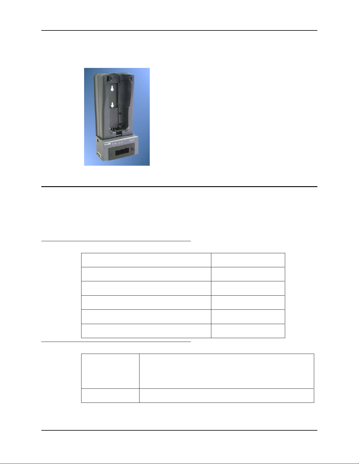
64 AC or DC Single Dock
AC or DC Single Dock
This dock holds one mobile device plus it has a cup to charge a
spare battery.
Both the battery in the mobile device and the spare battery charge
in less than seven hours.
A full charge in both batteries is maintained by a trickle charge.
Three lights on the front of the dock indicate the charging
process.
Figure 4-4 AC or DC Singledock
AC Singledock
Components
Specifications
The AC Singledock is intended for use where a mobile device is used in batch operation, and must
be stored, charged, and communicated with just as with the Multidock. However, the AC
Singledock is typically used when the mobile device user does not return to a central depot. In this
case each user must independently communicate from the client device to the host. This is
typically done via a dialup modem to the host.
AC Singledock 2330A010ACSINGDOCK
9600 Baud Terminator 2330A017RS485SLOW
115K Baud Terminator 2330A016RS485FAST
Straight Through Cable for Connection to Modem 6200L201
Null Modem Cable for Direct PC Connection 6200L200
AC Power Adapter 1300A303PSACWW
Communication
Interface
One RS232 communication port (25 pin DTE) for host connection.
One RS485 communications port (9 pin D connector). This port allows
AC Singledock to be used as RS232 to RS485 converter at beginning
of Multidock chain.
Baud Rate 9600 baud or 115K baud, half duplex, selectable with Terminator
MX1 Cradle Reference Guide E-EQ-MX1DKRG-B
Page 73
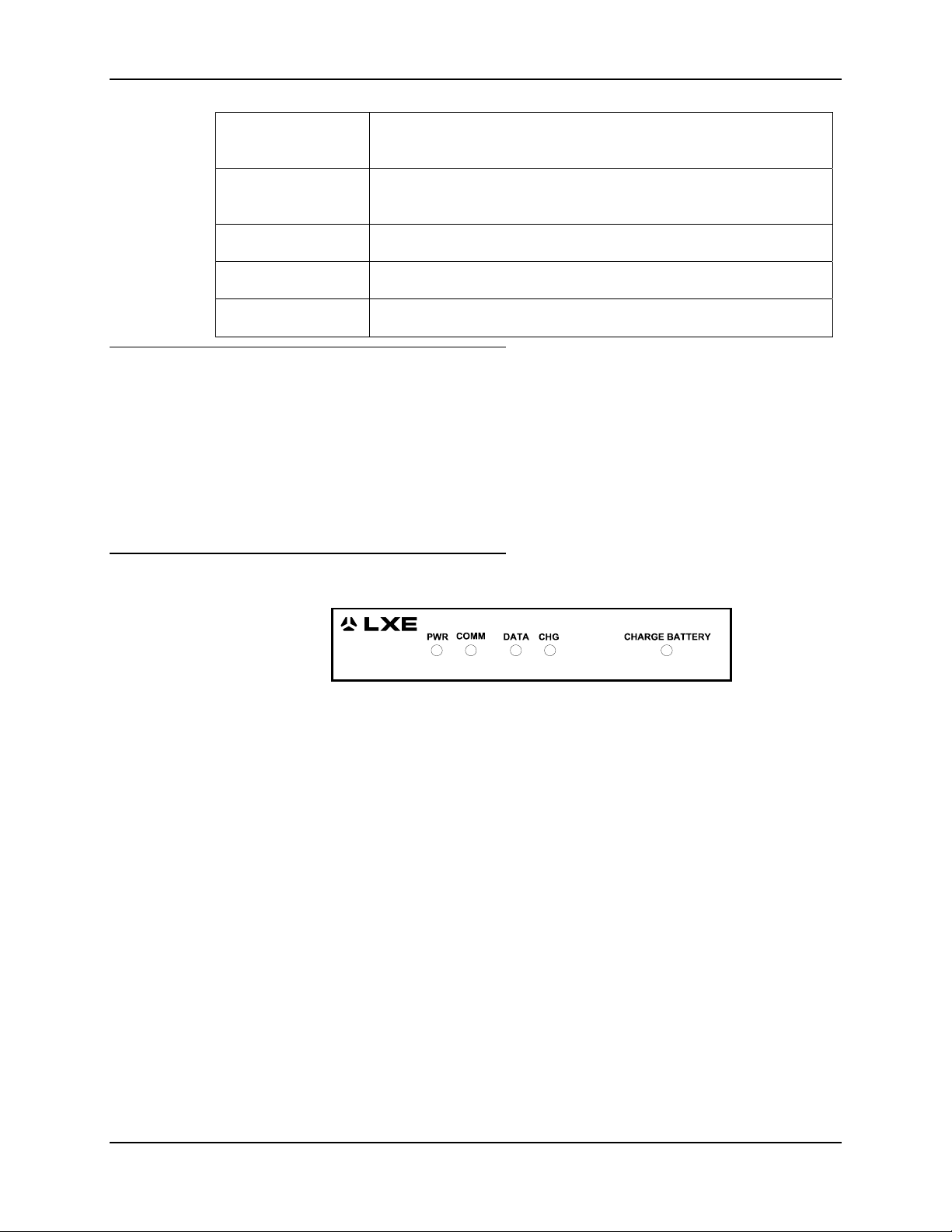
AC or DC Single Dock 65
Indicators DATA, CHG, PWR, COMM, and CHARGE BATTERY for spare
battery, either green or unlit.
Battery Charging Fully charges spare battery within 7 hours and fully powers terminal in
addition to charging battery. Trickle charge maintains full charge.
Dimensions 5.77” wide x 12.5” high x 3.25” deep
Temperature 0°C to 50°C, 5% to 95% humidity, non-condensing
Power Input 110-250 VAC, 50/60 Hz
AC Singledock Installation
1. Install AC Singledock on a wall.
2. Insert a mobile device and spare battery in the AC Singledock.
3. Connect power source to the Singledock.
4. Dock Power LED illuminates. The spare battery begins to recharge.
5. Turn the mobile device on.
Indicators
6. You are ready to begin host communication.
Figure 4-5 AC Singledock Indicators
PWR When green, the Singledock is receiving AC power.
COMM When solid green or flashing green, the host is sending data to the mobile
device.
DATA When solid green or flashing green, the Singledock is sending data to the
host.
CHG When solid green, the battery in the mobile device is being charged. When
dark, the battery in the mobile device is fully charged and is receiving a
trickle charge to maintain the full charge.
CHARGE
BATTERY
E-EQ-MX1DKRG-B MX1 Cradle Reference Guide
When solid green, the battery in the battery charger is being charged. When
dark, the battery in the charger is fully charged and is receiving a trickle
charge to maintain the full charge.
Page 74
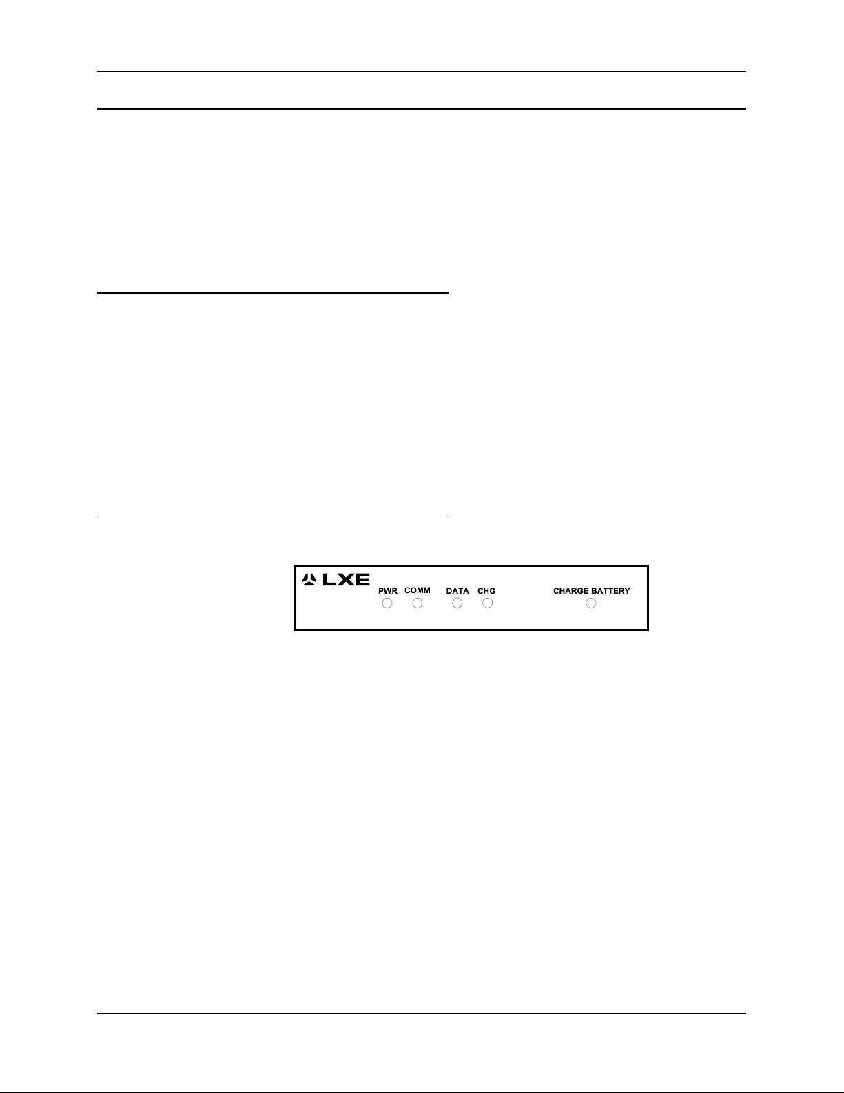
66 AC or DC Single Dock
DC Singledock
The DC Singledock is intended for use where a mobile device needs to be cradled in a vehicle
during the day’s operation. The DC Singledock charges the main battery while docked, powers
the mobile device and provides a means for the client device to communicate to on-board devices
such as printers or Wide Area Network communications devices. The DC Singledock is powered
directly from the motor vehicle’s power system, and designed to operate in the temperature and
vibration conditions typically found in over-the-road vehicles.
If extreme vibration or outdoor environments are anticipated, contact your LXE representative for
information about the LXE Fork Lift Cradle.
DC Singledock Installation
1. Assemble mounting bracket.
2. Install Mounting Bracket on a stable, flat surface. Use the LXE Vehicle Mounting Bracket or
an equivalent mounting assembly.
3. Insert a mobile device and spare battery in Docking Bracket Assembly.
4. Connect power source to the Singledock.
5. Dock Power LED illuminates. The spare battery begins to recharge.
Indicators
6. Turn the mobile device on.
7. You are ready to begin standalone operation.
Figure 4-6 DC Singledock Indicators
PWR When green, the Singledock is receiving DC power.
COMM When solid green or flashing green, the in-vehicle computing equipment is
sending data to the mobile device.
DATA When solid green or flashing green, the Singledock is sending data to the
in-vehicle communications equipment.
CHG When solid green, the battery in the mobile device is being charged. When
dark, the battery in the mobile device is fully charged and is receiving a
trickle charge to maintain the full charge.
CHARGE
BATTERY
MX1 Cradle Reference Guide E-EQ-MX1DKRG-B
When solid green, the battery in the battery charger is being charged. When
dark, the battery in the charger is fully charged and is receiving a trickle
charge to maintain the full charge.
Page 75

AC or DC Single Dock 67
Components
DC Singledock and DC Power Cable Assembly 2330A011DCSINGDOCK
Vehicle Bracket 2330A012VMTBRKT
Specifications
Communication
Interface
Indicators DATA, CHG, PWR, COMM, and CHARGE BATTERY for spare
Battery Charging Fully charges spare battery within 7 hours and fully powers terminal in
Dimensions 5.77” wide x 12.5” high x 3.25” deep
Temperature -20C to 55C, 5% to 95% humidity, non-condensing
Power Input 11 - 16.5 VDC, 0.75 ams max
One RS232 communications port (25 pin DTE) for in vehicle
connection.
battery, either green or unlit.
addition to charging battery. Trickle charge maintains full charge.
E-EQ-MX1DKRG-B MX1 Cradle Reference Guide
Page 76
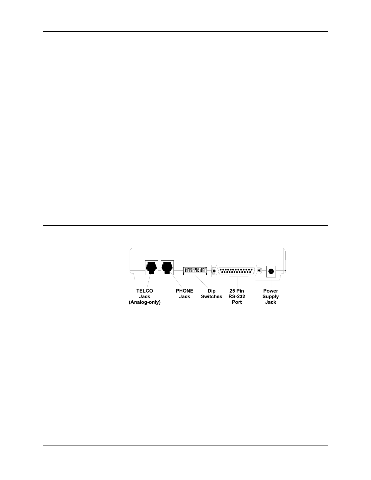
68 Modem
Modem
Note: Without exception, use only the modem-specific cables and power supply that came with
the modem. Connect to an analog telephone line. The modem will be damaged if a digital
telephone line is used.
The 33.3K Baud Modem allows offsite multidock or singledock systems to communicate with the
host PC. The host PC is connected to a local modem that receives signals from the remote modem
over telephone lines.
There are only a few requirements when using a modem:
• Use an analog telephone line for modem connection. Digital telephone lines will damage
the modem.
• Use only the modem specific power adapter and LXE RS232 serial cables that were
delivered with the modem.
• Modem connection to a Multidock series requires an LXE RS232 to RS485 converter and
a Multidock cable.
• Modem connection to a PC host requires an LXE 25 pin RS232 cable. Do not use a null
modem cable.
Installation
Note: Multidock and Singledock RS232 ports do not support hardware handshaking.
Figure 4-7 Modem Connectors and Dip Switches
1. Place modem on a stable, flat surface.
2. Cable the modem to the Singledock or Multidock or host.
3. Connect the modem to an analog phone line.
4. Connect the modem’s power supply.
5. You are ready to begin host communication.
MX1 Cradle Reference Guide E-EQ-MX1DKRG-B
Page 77
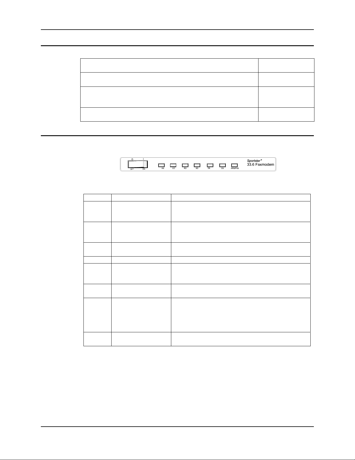
Modem 69
Components
33.3K Baud Modem 9000A064MODEM
Null Modem Cable for Direct PC Connection 6200L200
AC Power Adapter 1300A303PSACW
W
Straight Through Cable for Connection to AC Singledock or Converter 6200L201
Indicators
Figure 4-8 Modem Indicators
Symbol Meaning Status
AA Auto Answer/Answer Answer mode: ON when set to Auto Answer, and when
answering a call; OFF when modem originates a call.
Light flashes when there is an incoming call.
CD Carrier Detect ON if modem receives a valid data signal (carrier_) from
a remote modem, indicating that data transmission is
possible. Always ON if CD override is ON.
RD Received Data Flashes when modem sends result codes or passes
received data bits.
SD Send Data Flashes when computer sends a data bit.
TR Data Terminal Ready ON if modem receives a DTR signal from computer.
Always ON (modem ignores DTR) if the DTR override
is ON.
CS Clear to Send ON until modem lowers CTS when transmit Data
hardware flow control is enabled.
ARQ/
FAX
OH Off Hook ON when modem accesses the phone line. OFF when
Error Control /
Fax Operations
Data Mode: Automatic Repeat Request. ON if modem is
set to Normal ARQ or ARQ Mode and successfully
establishes an error control connection. Flashes when
modem retransmits data to remote modem. Fax Mode:
Flashes to indicate fax mode.
modem is On Hook.
E-EQ-MX1DKRG-B MX1 Cradle Reference Guide
Page 78

70 Modem
Dip Switch Settings
Note: Dip switch is ON when switch is DOWN and OFF when switch is UP.
Switch
1
2
3
4
5
6
7
8
LXE
Setting Function
Off
On
On
Off
Off
Off
On
On
Data Terminal Ready (DTR Override
Off Normal DTR operations: computer must provide DTR signal for
On Modem ignores DTR (Override).
Verbal/Numeric Result Codes
Off Verbal (word) results.
On Numeric results.
Result Code Display
Off Suppresses result codes.
On Enables result codes.
Command Mode Local Echo Suppression
Off Displays keyboard commands.
On Suppresses echo.
Auto answer Suppression
Off Modem answers on first ring, or higher if specified in nonvolatile
On Disables auto answer.
Carrier Detect (CD) Override
Off Modem sends CD signal when it connects with another modem,
On CD always ON (Override).
Power on and ATZ Reset Software Defaults
Off Loads profile 0 or profile 1 configuration from user-defined
On Loads generic template from read only memory (ROM).
AT Command Set Recognition
Off Disables command recognition (Dumb mode).
On Enables recognition (Smart mode).
modem to accept commands; dropping DTR terminates a call.
memory (NVRAM).
drops CD on disconnect.
nonvolatile memory (NVRAM).
MX1 Cradle Reference Guide E-EQ-MX1DKRG-B
Page 79
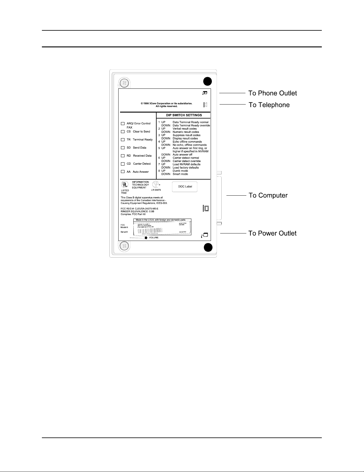
Modem 71
Modem / PC Setup
Figure 4-9 Modem Connections
Communications software allows you to change settings and issue commands to the modem
connected to the PC.
The communications software is preconfigured for optimal performance with the modem. Refer to
the software manual for any additional information.
E-EQ-MX1DKRG-B MX1 Cradle Reference Guide
Page 80

72 Mounting Brackets for Multidocks, AC and DC Singledocks
Mounting Brackets for Multidocks, AC and DC Singledocks
Note: Hardware (bolts, washers and wrench) required to attach the docks to a surface are not
supplied by LXE.
Wall Mount
• You will need eight each ¼” hardware, or equivalent fasteners, for mounting the
Multidock.
• You will need two each ¼” hardware, or equivalent fasteners, for mounting the
Singledock.
Vehicle Mount
• You will need four each ¼” hardware, or equivalent fasteners, to attach vehicle mount to
the surface.
Use the dimensions on the mounting diagrams to place the brackets.
Mounting Multidock to Wall
Note: LXE recommends the Multidock be mounted to a wall or other vertical, sturdy surface. If
placed on a table, the Multidock may tip over when the 2330 is inserted or removed from
the cradle.
The mounting holes are two inches apart, vertically, and 5.75 inches apart horizontally.
1. Place ¼” hardware in the mounting locations on the wall, allowing enough room between the
wall and the fastener head to hold the Multidock.
2. Guide the larger area of the keyhole openings over the fastener heads until the Multidock is
flush with the wall.
3. Pull down gently until all fastener heads are in the smaller area of the keyhole opening.
Tighten hardware.
Mounting AC Singledock to Wall
Note: LXE recommends the Singledock be mounted to a wall or other vertical, sturdy surface.
If placed on a table, the Singledock may tip over when the 2330 is inserted or removed
from the cradle.
The mounting holes are two inches apart, vertically.
1. Place ¼” hardware in the mounting locations on the wall, allowing enough room between the
wall and the fastener head to hold the Singledock.
2. Guide the larger area of the keyhole openings over the fastener heads until the Singledock is
flush with the wall.
3. Pull down gently until all fastener heads are in the smaller area of the keyhole opening.
Tighten hardware.
When mounting more than one Singledock, or a sequence of modems and Singledocks, allow
enough room between each unit for the power supply and modem cables.
MX1 Cradle Reference Guide E-EQ-MX1DKRG-B
Page 81
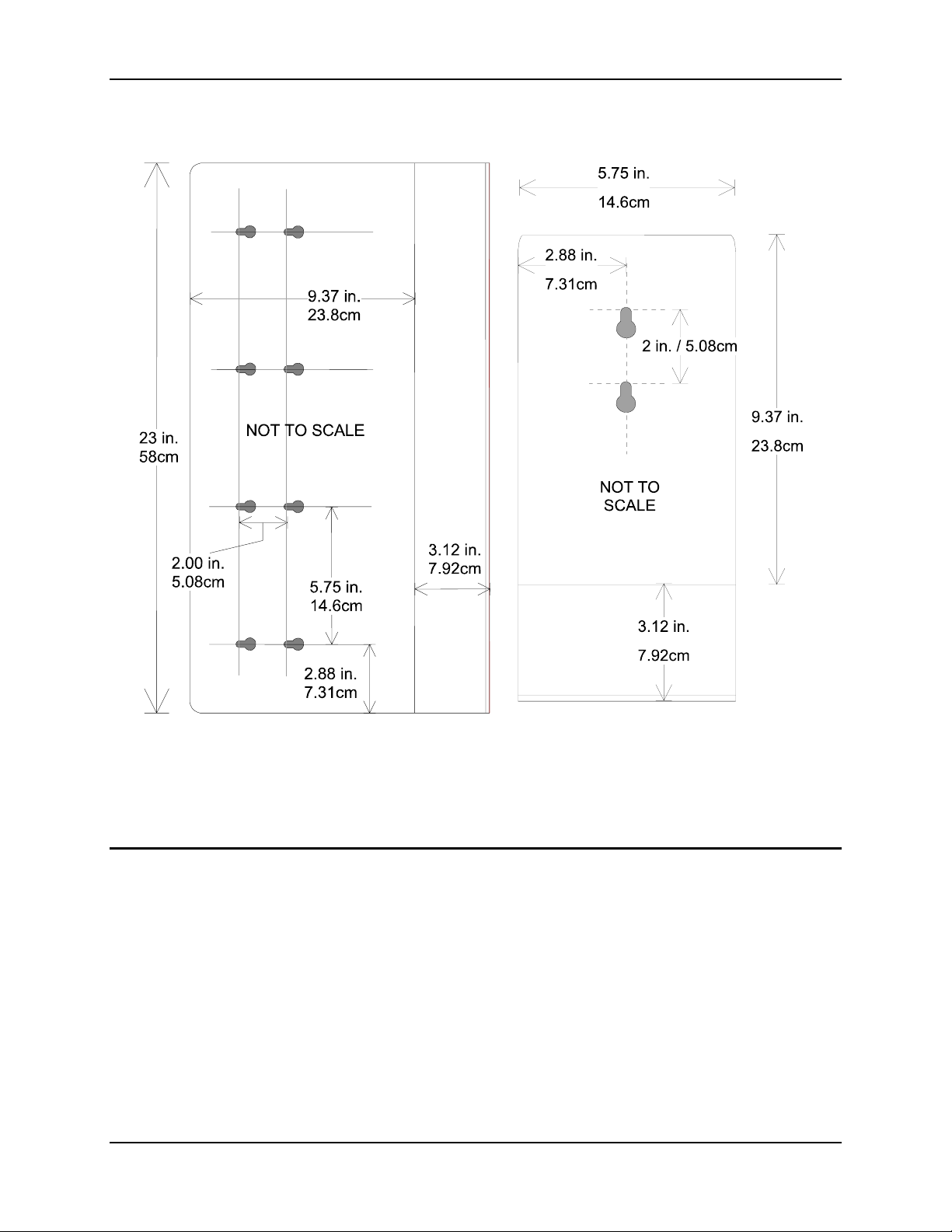
Mounting Brackets for Multidocks, AC and DC Singledocks 73
Multidock Singledock
Figure 4-10 Mounting Diagrams
Mounting in Sequence
Multidocks and Singledocks are designed to be touching each other when mounted in sequence.
When mounting more than one Multidock, or a sequence of Multidocks and AC Singledocks,
connect all cables and power supplies before final mounting. The cables are placed in the storage
areas in the back that are created when the units are mounted flush to each other.
E-EQ-MX1DKRG-B MX1 Cradle Reference Guide
Page 82
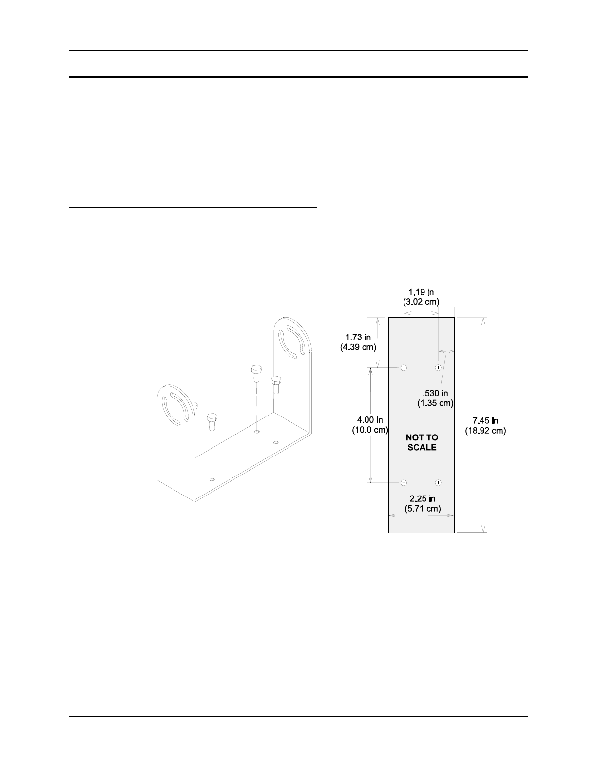
74 Mounting Brackets for Multidocks, AC and DC Singledocks
Vehicle Mounting and the DC Singledock
The DC Singledock is intended for mounting in typical over the road vehicles such as step vans or
semi trailer tractors. Because of the variety of vehicle configurations and personal driver
preferences, no one mounting configuration can suit all applications. LXE does offer a vehicle
mounting bracket that provides vibration isolation, but in many cases the user may want to
provide their own mounting hardware. Off the shelf cell phone mounting equipment or custom
mounting brackets could be used.
The mounting instructions that follow show the use of the LXE bracket and the mounting hole
pattern to be used if a custom mount is to be used.
LXE Vehicle Bracket
Install the Bottom Mounting Bracket portion of the mounting assembly to the vehicle using ¼”
(6.35mm) maximum diameter fasteners (not supplied by LXE).
Bottom Mounting Bracket
Mounting Footprint – Not to Scale
Fasten the backplate assembly to the DC Singledock using the thru holes in the backplate and the
threaded holes in the back of the Singledock. Four #8-32 fasteners are provided with the mounting
kit.
MX1 Cradle Reference Guide E-EQ-MX1DKRG-B
Page 83
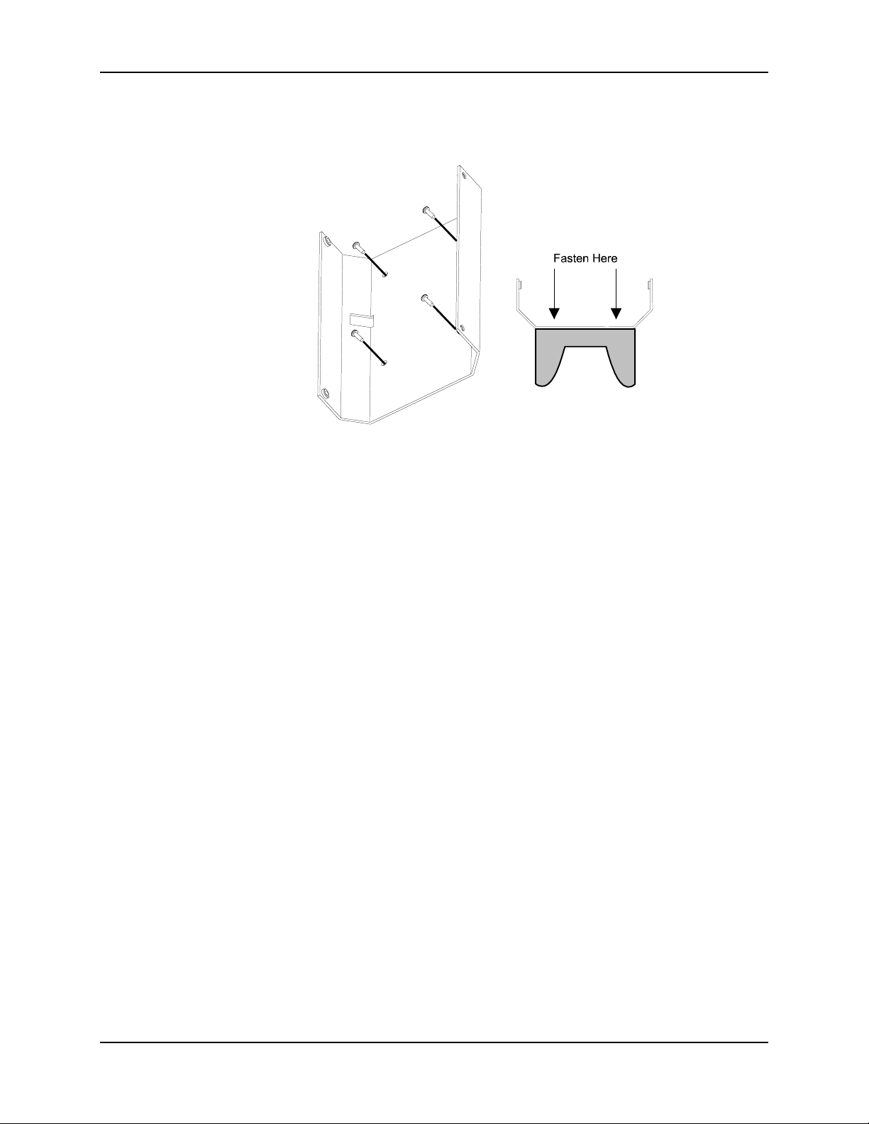
Mounting Brackets for Multidocks, AC and DC Singledocks 75
Figure 4-11 Fasten Backplate Assembly to DC Singledock
The DC Singledock is ready for cabling.
E-EQ-MX1DKRG-B MX1 Cradle Reference Guide
Page 84
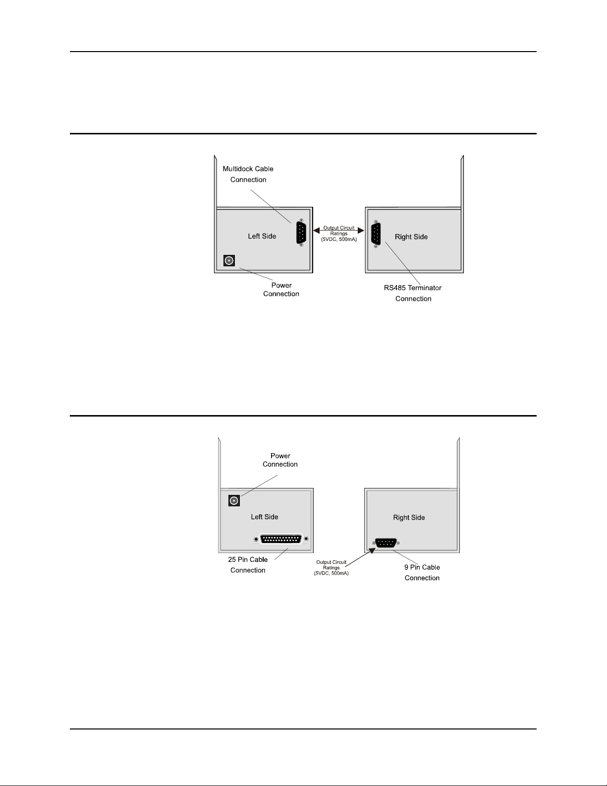
76 Cable Port Connections
Cable Port Connections
Complete all cabling before connecting the equipment to a power source.
Multidock Cabling
Figure 4-12 Multidock Cable Ports
Use the Multidock 9 pin cable to connect the Multidock to one of the following:
• An RS232 to RS485 converter.
• Another Multidock.
• An AC Singledock.
• An RS485 terminator.
AC Singledock Cabling
Use the 9 pin port to connect to a Multidock.
Figure 4-13 AC Singledock Cable Ports
Use the 25 pin port to connect to one of the following:
• A 25 pin port on a modem.
• A 25 pin serial port on the host PC.
MX1 Cradle Reference Guide E-EQ-MX1DKRG-B
Page 85
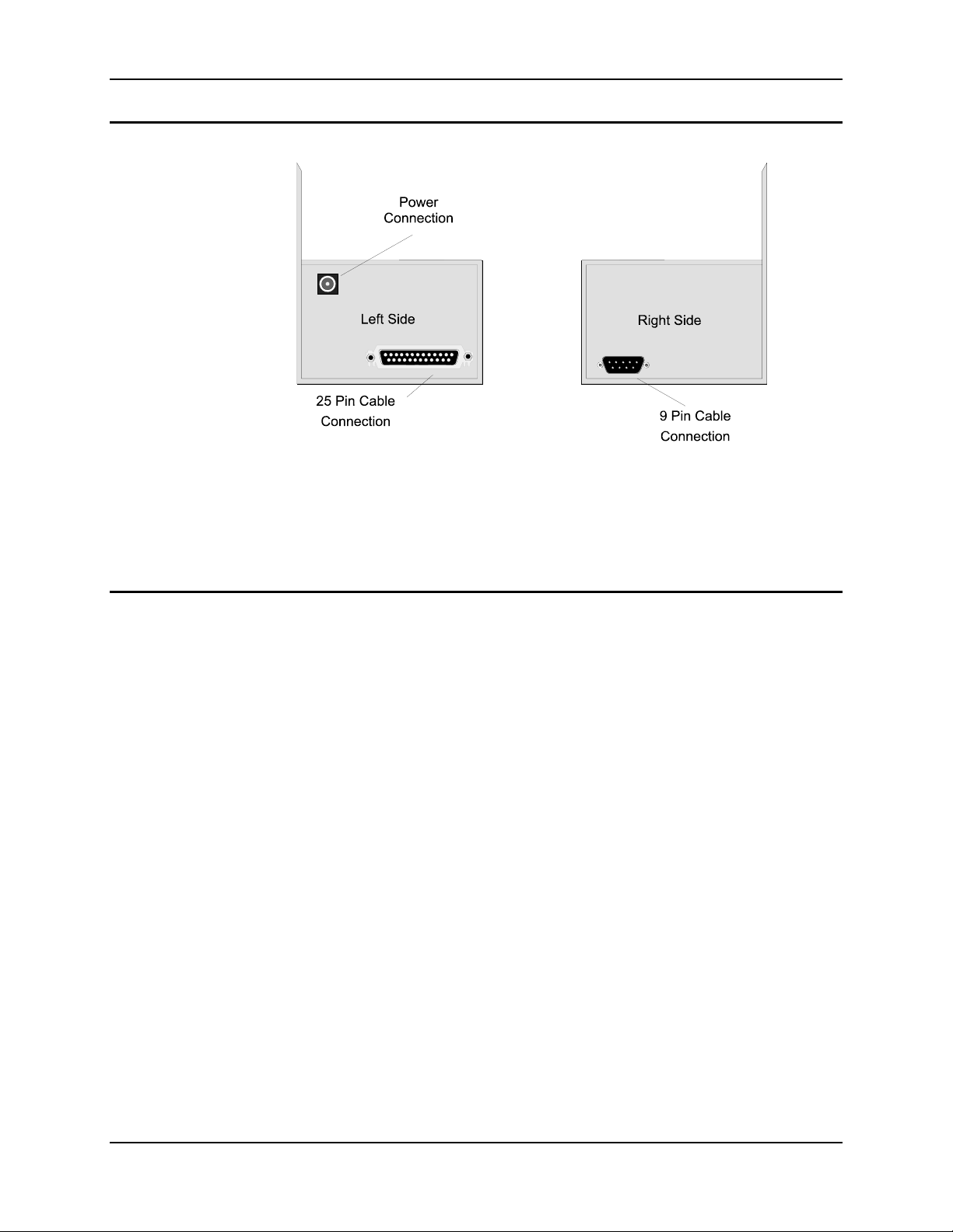
Cable Port Connections 77
DC Singledock Cabling
Figure 4-14 DC Singledock Cable Ports (Port on Right Side is not Connected)
Use the 25 pin port to connect to one of the following:
Modem Cabling
1. Connect a 25 pin cable to the 25 pin port on the modem and to one of the following:
2. Plug the power adapter into the power supply jack and into a standard wall outlet.
3. Plug one end of the (supplied) telephone cord into the TELCO jack and the other end
Note: To use the modem and telephone through the same phone wall jack, plug the telephone’s
• In-vehicle computing equipment.
• In-vehicle communications equipment.
• A 25 pin port on a Singledock.
• A 25 pin serial port on a PC.
• An RS232 to RS485 converter.
Note: When connecting a modem to a PC, note which PC serial port is selected. The PC
port selected may be labeled COM, MODEM, RS-232 or SERIAL.
into an analog telephone wall jack.
cord into the modem’s PHONE jack.
E-EQ-MX1DKRG-B MX1 Cradle Reference Guide
Page 86
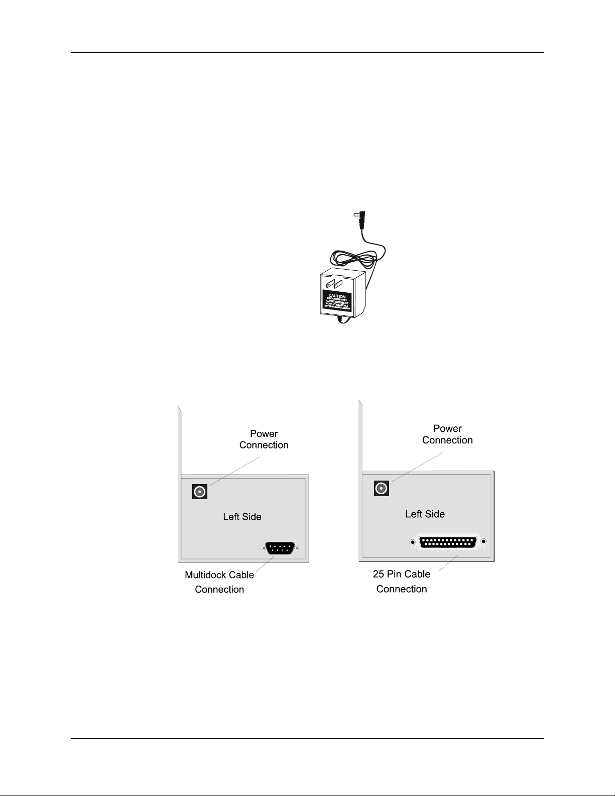
78 Power Adapter, 110-240 VAC
Power Adapter, 110-240 VAC
Used for Multidocks and AC Singledocks.
The external power supply may be connected to a 110V, 60Hz supply using the appropriate
detachable cordset. In all cases, connect to a properly grounded source of supply provided with
maximum 15 Amp overcurrent protection (10 Amp for 240V circuits).
1. Connect the detachable cordset provided by LXE to the external power supply (IEC 320
connector).
2. Plug cordset into appropriate, grounded, electrical supply receptacle (AC mains).
3. Connect the pin end to theMultidock or Singledock power connector by aligning the
connector pin to the power connector; and push down firmly.
Multidock Connector Singledock Connector
4. The Power LED on the Multidock or Singledock illuminates when it is receiving power.
MX1 Cradle Reference Guide E-EQ-MX1DKRG-B
Page 87
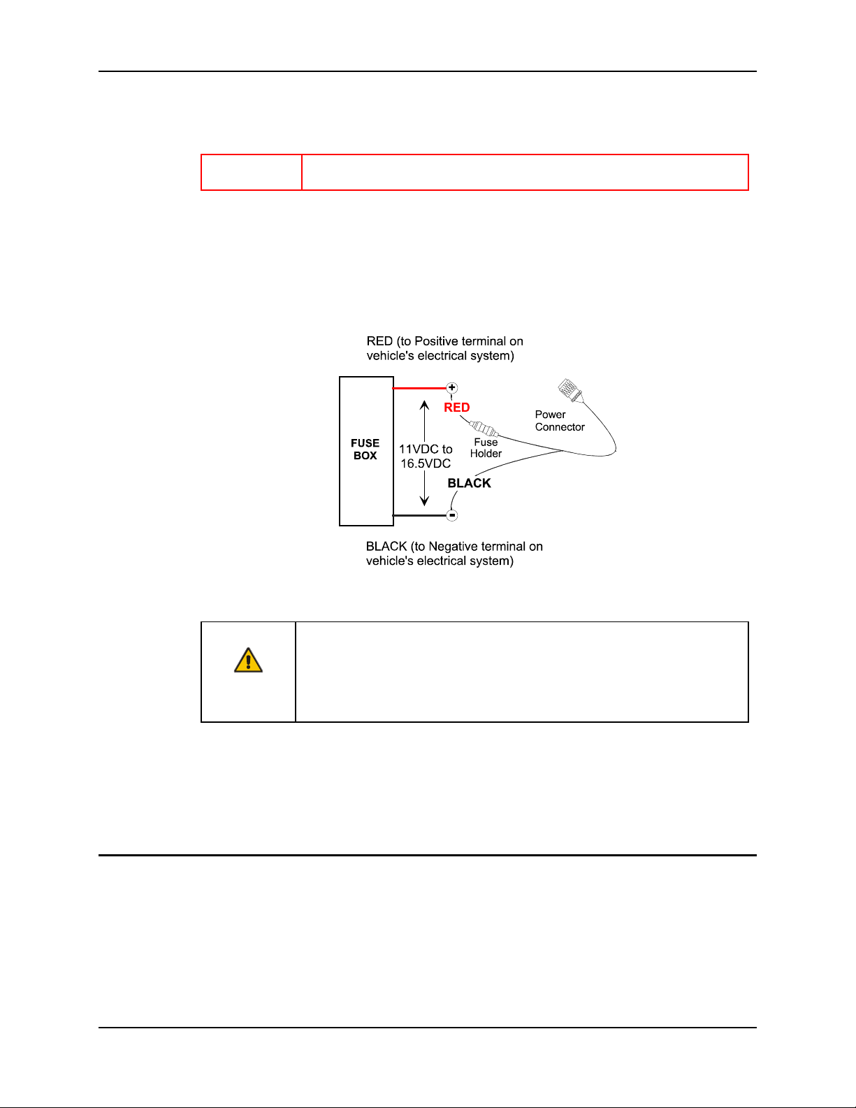
Vehicle 12VDC Connection 79
Vehicle 12VDC Connection
Important Equipment is designed to use 11 to 16.5 volt power source only.
The DC Singledock is designed for use with any DC power source within the range of 11 V to
16.5 V.
It is recommended that the vehicle cable be connected to an unswitched outlet on the vehicle’s
fuse box. This connection method reduces the chance of interference from the vehicle’s charging
system.
Caution:
When the Singledock is connected to an unswitched outlet on the fuse box the mobile device
battery will always receive a charge from the vehicle battery. If the unit is left turned on for
extended periods of time, the mobile device could drain the vehicle battery.
If the Singledock is connected to a switched outlet on the fuse box the mobile device and battery
will only charge when the vehicle is on. This will eliminate the problem of draining the vehicle
battery.
Fuse Replacement
The unit uses a 250V, 1.5A (fast blow), high current interrupting rating fuse that is externally
accessible and user replaceable. Should it need replacement, replace with same size, rating and
type of fuse (such as Bussman AGC-1 1/2).
Figure 4-15 Proper Connection of the Vehicle Cable
Correct electrical polarity and grounding is required for safe and proper
installation.
Only connect to a negative ground DC supply circuit.
Not for installation to positive ground circuits.
E-EQ-MX1DKRG-B MX1 Cradle Reference Guide
Page 88

80 Vehicle 12VDC Connection
MX1 Cradle Reference Guide E-EQ-MX1DKRG-B
Page 89
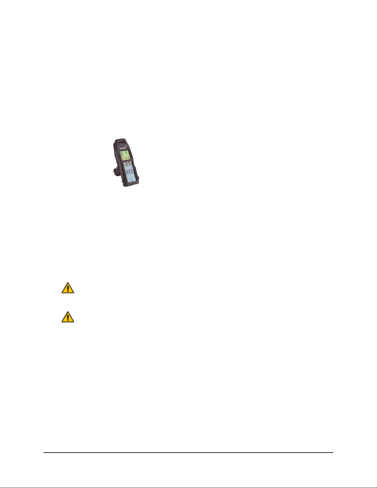
Introduction
Chapter 5 Battery Pack Chargers
The LXE publication “Getting the Most from Your Batteries” is available on the LXE Manuals
CD and is a single-source guide to battery management. The document contains information about
battery recharging, conditioning, and other pertinent issues, portions of which are duplicated in
this chapter.
Attention:
The MX1 Intrinsically Safe device battery pack is
NOT compatible with these battery pack chargers.
The battery pack may be damaged if placed in an
unauthorized MX1-IS battery charger/analyzer. The
MX1 I-Safe
MX1-IS keypad is bright blue in color.
Handling Batteries Safely
Never dispose of a battery in a fire. This may cause an explosion.
Do not replace individual cells in a battery.
Be careful when handling NiMH batteries. If a battery is broken or shows signs of leakage do not
attempt to charge it. Dispose of it using proper procedures.
Caution:
Caution:
Nickel-based cells contain a chemical solution which burns skin, eyes, etc. Leakage from cells is
the only possible way for such exposure to occur. In this event, rinse the affected area
thoroughly with water. If the solution contacts the eyes, get immediate medical attention.
NiMH batteries are capable of delivering high currents when accidentally shorted. Accidental
shorting can occur when contact is made with jewelry, metal surfaces, conductive tools, etc.,
making the objects very hot. Never place a battery in a pocket or case with keys, coins, or other
metal objects.
Battery Warning Messages on Computers
Many LXE battery operated units have been programmed to either display a warning message
and/or emit distinctive beeps when battery capacity has fallen to a pre-determined level.
The warning messages displayed on the screen may be similar to the following:
Low Battery Warning
Replace Battery Now
Critically Low
System Will Power Off In n Seconds
E-EQ-MX1DKRG-B MX1 Cradle Reference Guide
Page 90

82 Battery Pack Chargers
Do not ignore the warnings. The messages are displayed to warn you that the battery must be
replaced or data will be lost.
Follow the instructions displayed on the screen or listed in the respective equipment’s reference
guide. The instructions are directed toward proper unit shutdown and battery replacement.
Optional Clip-on Portable Charger for the 2335 and MX1
The 2335 and MX1 Battery Pack can be fully charged using the Clip-on Portable Charger. A
complete recharge of a dead main battery with the mobile device in an Off state will take 8 hours.
Charge only at ambient temperature above 32°F / 0°C.
1. Charging LED
2. Power LED
3. Catch pins
4. Spring loaded arms
5. Power Jack connector
Figure 5-1 Clip-on Portable Charger
Note: The unit will not operate correctly on charger power without a battery installed in the
mobile device.
The Clip-on Portable Charger must be powered by one of the following:
• Cigarette Lighter Adapter
• Power Supply, External, AC, US
• Power Supply, External AC, International
How To
Snap the Clip-on Portable Charger to the base of the mobile device by aligning the catch pins with
the notches in the Battery Door.
Plug the Wall Mount or the Cigarette Lighter adapter into a power source before connecting the
Power Jack to the Clip-on Portable Charger.
Remove the Clip-on Portable Charger from the mobile device by depressing the spring loaded arm
at the base of the module.
Then remove the AC adapter from its power source.
Clip-on Portable Charger LEDs
The green Power LED on the Clip-on Portable Charger indicates voltage is present in the charger.
The yellow Charging LED indicates the battery is being charged. When a battery is present in the
mobile device, the Charging LED is always lit.
The intensity of the Charging LED indicates the following states:
Bright The Portable Charger is using its high charge rate. The charger detected a battery
low state and is charging the battery until a full battery condition is detected.
MX1 Cradle Reference Guide E-EQ-MX1DKRG-B
Page 91
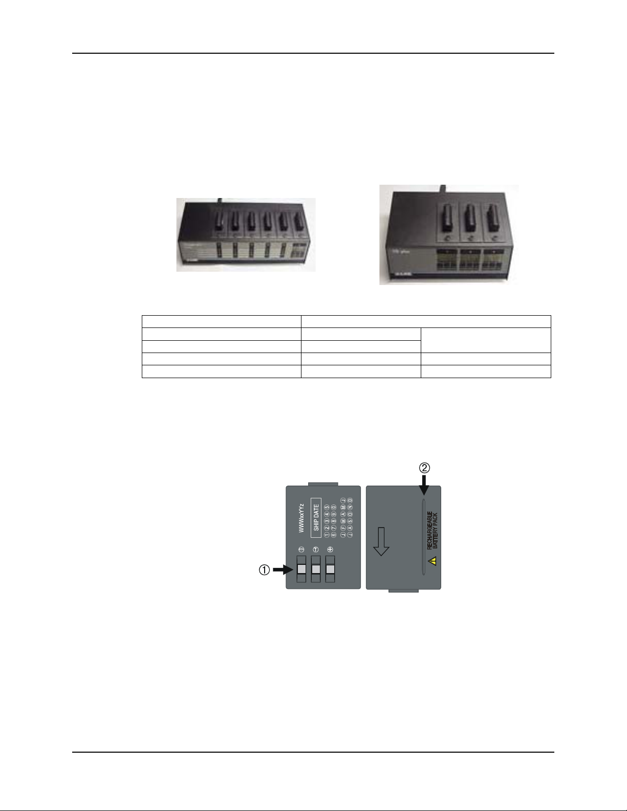
Battery Pack Chargers 83
Dim The Portable Charger is using its low charge rate. The charger detected a full
battery or that the battery only requires “topping off.”
Unlit There is no battery in the mobile device. No charge rate is being applied. The
indicator does NOT turn off when charging is complete.
Main Battery Pack Charger for the Mobile Device
Figure 5-2 Main Battery Pack Chargers / Analyzers
Charges NiMH Battery Pack
6 Unit Charger/Analyzer 2330A378CHGR6WW
3 Unit Battery Analyzer 2330A379ANLZR3WW
Power Supply, AC, US 2335A301PSACUS
Power Supply, AC, International 2335A302PSACWW
The charger/analyzer used with the NiMH batteries for the 2330, 2335 and MX1 have from three
to six battery cups.
2330A381BATT1500 and
2330A380BATT1500
There is one Test or Maintenance station, which is the last slot on the far right. This station will
ultimately charge a battery. Mounted below the Analyzing Station is the LED Information Center
and three dome switches, labeled Condition, Discharge and Analyze.
Figure 5-3 1500 mAh (NiMH) Main Battery
1. Battery Contacts
2. Positioning Key
Named for the Nickel-Metal hydride construction – Main Battery packs power the 2330, 2335 and
the MX1 (except MX1-IS).
The minimum battery life before replacement is 300 – 500 charge/discharge cycles.
E-EQ-MX1DKRG-B MX1 Cradle Reference Guide
Page 92
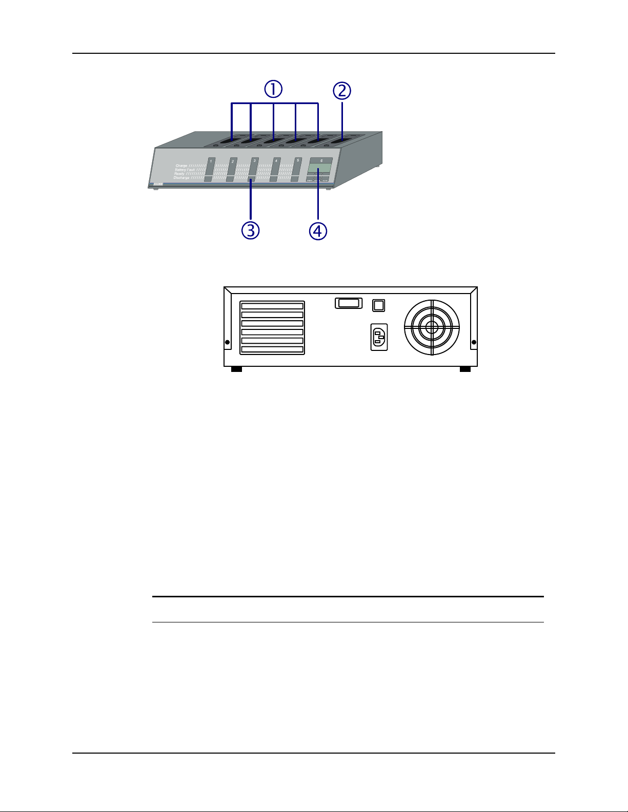
84 Battery Pack Chargers
1. Battery Adapter or Charging
Cup
2. Test Station of Maintenance
Station
3. Function Indicators
4. LCD Information Center
Figure 5-4 Six Cup Charger/Analyzer
Figure 5-5 Back View of a Charger/Analyzer
Note: The power supply cord is the main disconnect device.
The rear panel contains some or all of these features:
• A/C cable receptacle.
• Protection provided by either a 2 amp SLO BLO fuse or a 1 or 2 amp circuit breaker.
• Power or On/Off switch.
• Fan for temperature control.
LXE multi-unit charger/analyzers perform the same four functions: Charge, Discharge, Analyze
and Condition.
The function results are displayed on the LCD Information Center or the indicator strip under each
battery adapter or cup.
Display Description
DISCHARGE The analyzer is discharging the battery.
CHARGE The analyzer is charging the battery.
CONDITION The analyzer fully charges, discharges, and recharges the battery
three times and displays the capacity of the battery. At the end of
the three-step process, the analyzer charges the battery.
MX1 Cradle Reference Guide E-EQ-MX1DKRG-B
Page 93

Battery Pack Chargers 85
Display Description
1.2.3 Cycle numbers indicating which cycle the analyzer is currently
performing in the Conditioning of the battery.
ANALYZE The analyzer fully charges, discharges, and recharges the battery
once and displays the capacity of the battery.
BAT.FAULT The battery is shorted (contains 2 volts or less) or the battery has
not reached 6 volts for a 6 cell battery (or 5 volts for a 5 cell
battery) after fifteen minutes of the Charge cycle.
READY The battery is ready for use.
mAh The capacity reading of the battery.
V The voltage of the battery.
Note: Do not remove the battery, or power the analyzer on and off, in the middle of a process.
The process will start at the beginning when power, or the battery, is restored.
E-EQ-MX1DKRG-B MX1 Cradle Reference Guide
Page 94
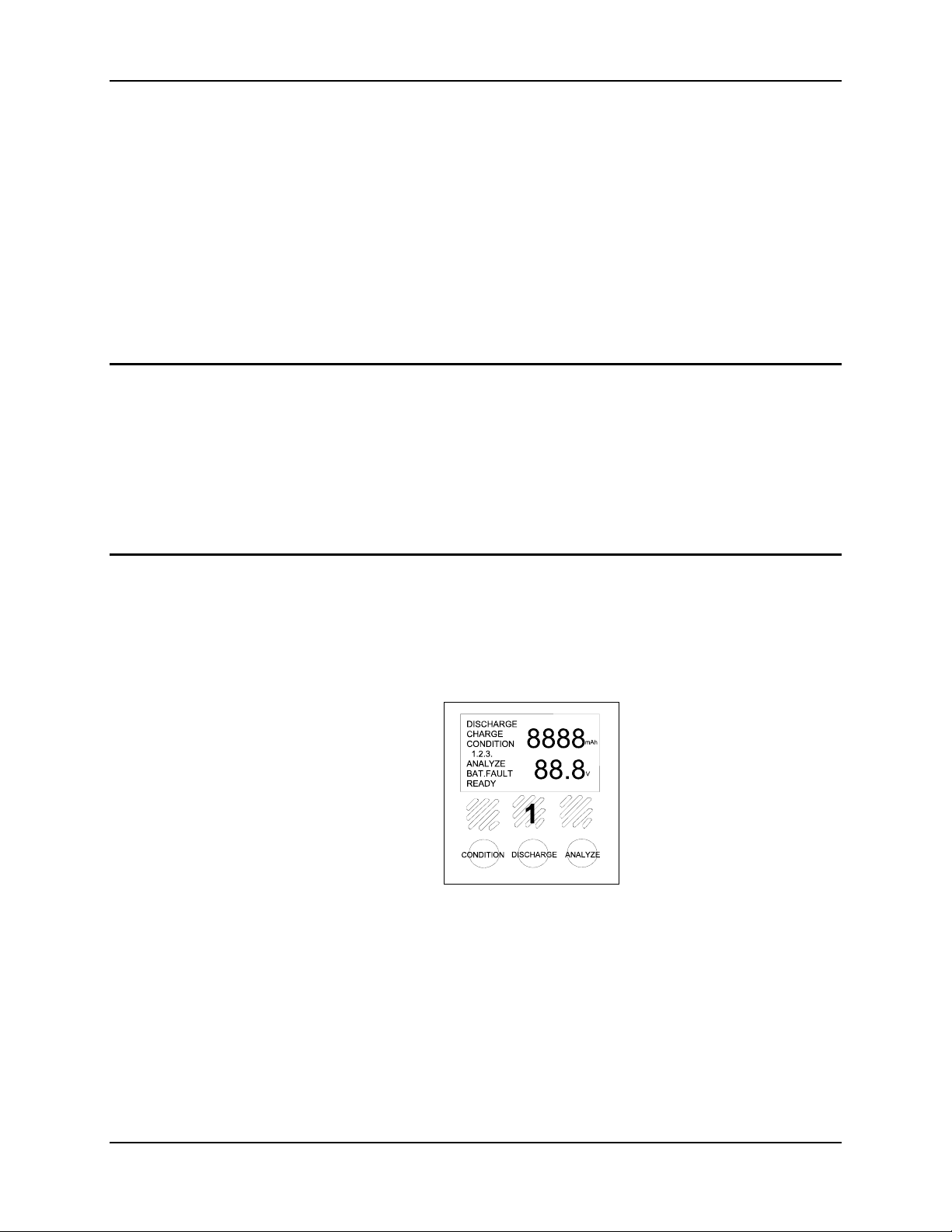
86 Battery Pack Chargers
Using a 3 or 6 Bay Charger/Analyzer
Place the charger/analyzer on a flat surface, near an AC power supply and in a location that is
protected from passing vehicles or falling objects.
Check all batteries for cracks, chips or leaks before placing in the charger/analyzer. If the battery
is damaged it cannot be used in the charger/analyzer and must be discarded properly. Verify that
the battery type is the correct type for the selected charger/analyzer – NiCad batteries in NiCad
chargers, NiMH batteries in NiMH chargers, Li-Ion batteries in Li-Ion chargers..
Note: When the battery does not fit snugly in the battery charging cup, the battery is the
incorrect type for that particular analyzer and must be removed.
Getting Started
If the unit is unplugged, confirm that the charger/analyzer power switch is in the Off position. The
power switch is on the rear panel. The “I” indicates the On position and the “O” indicates the Off
position. If the unit has a rear panel voltage selector switch, set the switch to match the line
voltage it will be receiving.
Connect the AC plug from the rear of the analyzer to a convenient and appropriate (check the user
guide or the voltage label on the analyzer) 115VAC or 220/240VAC outlet. Some analyzers
require 220/240VAC only.
Power On
Note: Remove all batteries from the charger/analyzer before turning the unit on.
Press the rear panel Power Switch to the On position (On “I”, Off “O”).
When powered on, the LCD Information Center illuminates and, within the first 5 seconds,
displays diagnostic information gathered from the charger/analyzer.
Figure 5-6 Sample Diagnostic Display
When the diagnostic cycle is complete, the LCD screen is blank and the charger/analyzer battery
stations are in “Standby” mode, ready to begin charging batteries.
The “V” or volts message should increase during the charging cycles and decrease during the
discharge cycles. During mode operations, the mAh display continuously tracks the depleted
energy or capacity of the battery. The message displays the capacity in increasing 11 mAh
increments, during the discharge cycles.
Note: When screens are blank, analyzer is ready for batteries.
MX1 Cradle Reference Guide E-EQ-MX1DKRG-B
Page 95
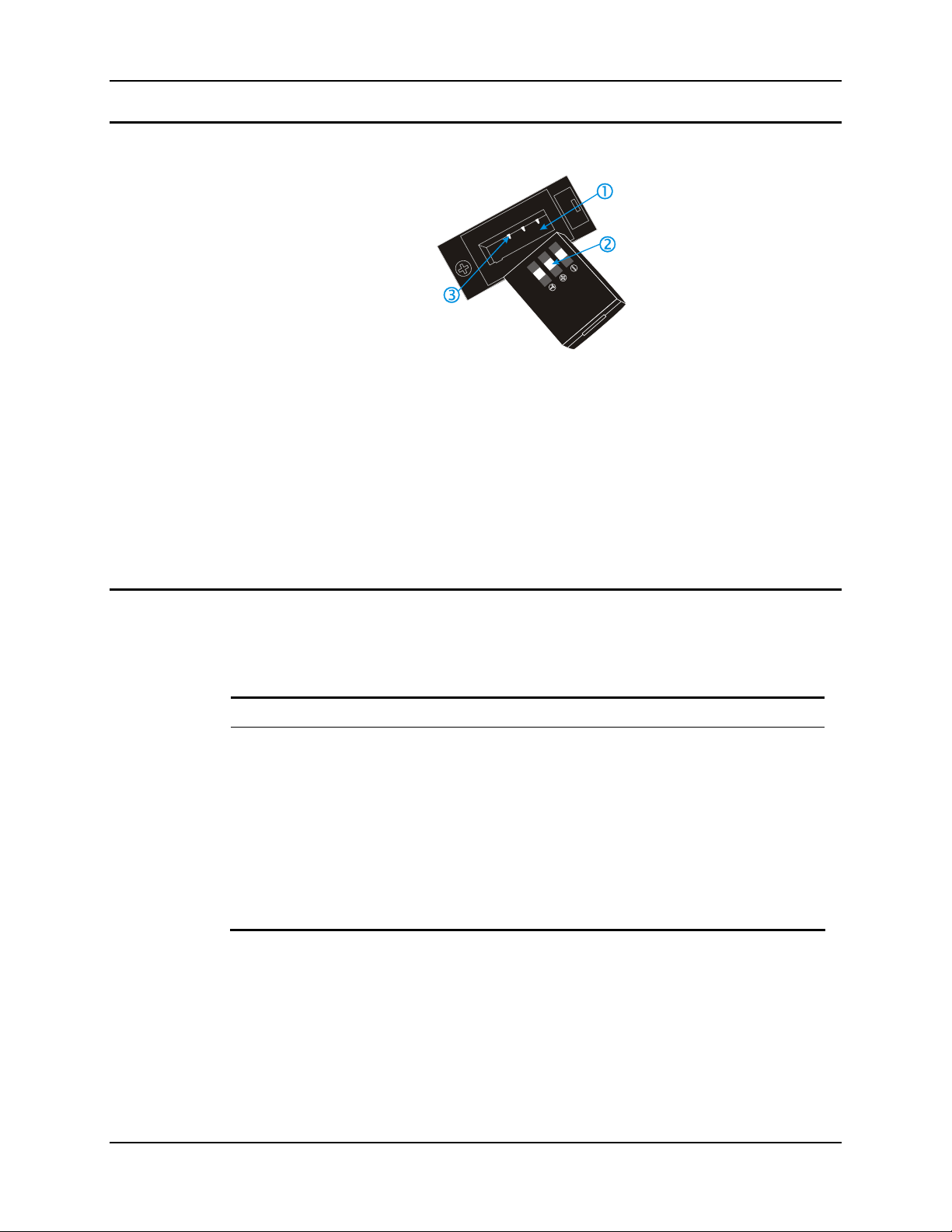
Battery Pack Chargers 87
Insert Battery
Figure 5-7 Battery Pack and Charging Cup
1 Battery Adapter or Charging Cup
2 Battery Contacts on Battery
3 Battery Contacts in Adapter or Charging Cup
Place the battery into a charging cup. Be certain the polarity is correct and the battery contacts
align with the adapter contacts.
When using a charger/analyzer for NiMH batteries, and the battery is installed in the Test or
Maintenance station, the letter “H” is displayed during the Charge mode only.
Select A Function
Do not remove the battery, or power the analyzer on and off, in the middle of a process. The
process will start at the beginning when power, or the battery, is restored. When the first part of a
process is Discharge, the available capacity in the battery will be discharged again.
Use This Mode When You …
Condition Prepare a new battery for use or restore a deficient battery to
Charge Want to fast charge a battery and maintain it’s full charge capacity
Analyze Need to measure battery capacity. This process first discharges then
Discharge Want to verify the performance of another battery charger or check
Note: Batteries are Conditioned and/or Analyzed in the Test or Maintenance station only.
maximum available power.
via trickle charge until needed.
charges the battery. The measured result can be compared against
the battery specs.
for excessive “stand-loss.”
E-EQ-MX1DKRG-B MX1 Cradle Reference Guide
Page 96
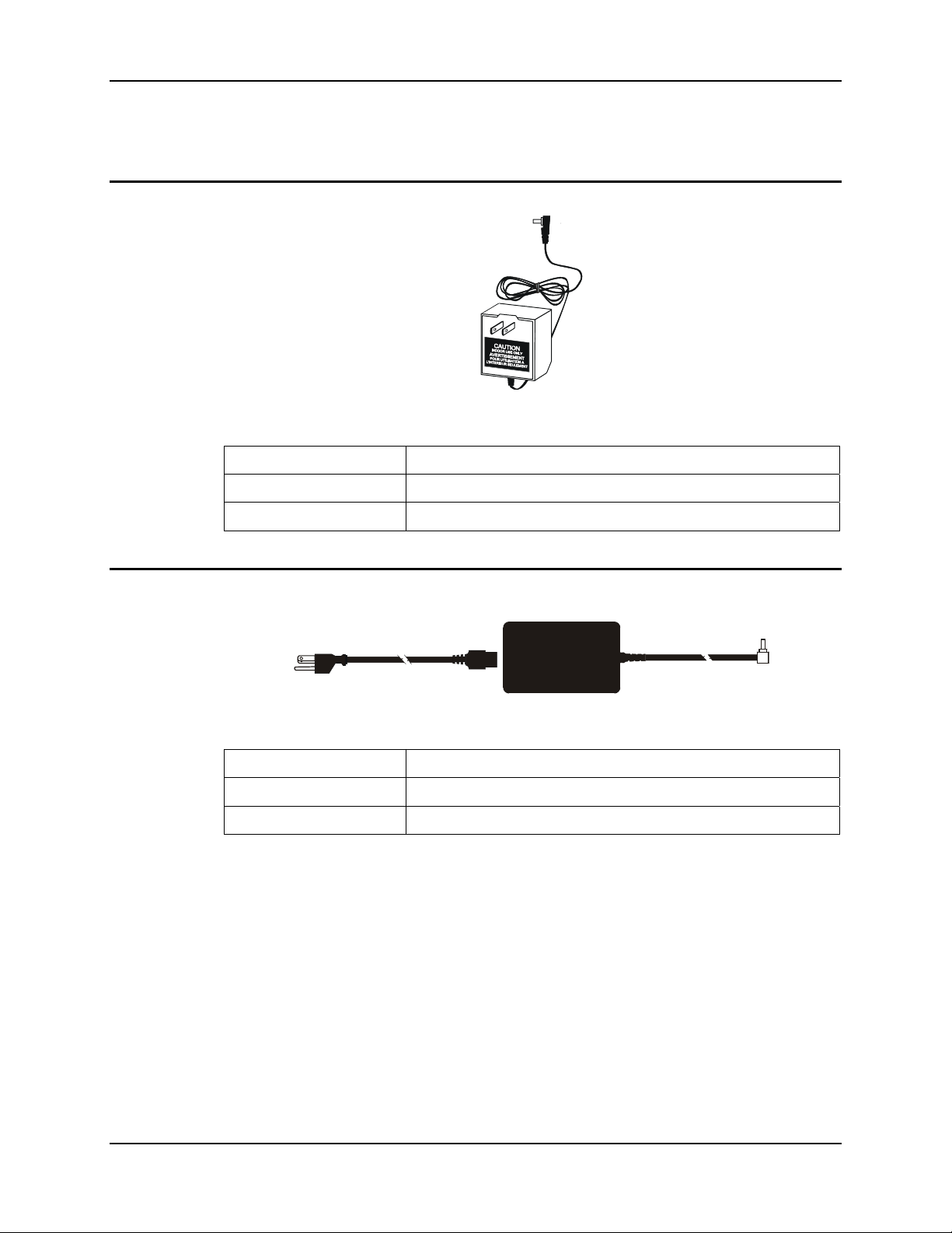
88 Battery Pack Chargers
AC Adapters for 3 and 6 Bay Battery Chargers
US AC Wall Adapter
Figure 5-8 US AC/DC 12V Power Supply
Operating Temperature 32°F to 104°F (-0°C to 40°C)
Storage Temperature -22°F to 140°F (-30°C to 60°C)
Operating Humidity Up to 90% non-condensing at 104°F (40°C)
International AC Adapter
Operating Temperature 32°F to 104°F (-0°C to 40°C)
Storage Temperature -22°F to 140°F (-30°C to 60°C)
Operating Humidity Up to 90% non-condensing at 104°F (40°C)
Figure 5-9 International AC/DC 12V Power Supply
MX1 Cradle Reference Guide E-EQ-MX1DKRG-B
Page 97

9
9-pin DCE port .....................................................47
A
AC and DC Singledock ........................................64
AC Singledock......................................................64
Indicators ............................................................65
Installation ..........................................................65
specifications.......................................................64
Aluminum spacer..................................................22
Attach the Left and Right Brackets.......................30
Attach the Passive Bracket ...................................30
attach the Upper Mounting Bracket to the cradle
assembly ...........................................................33
B
batch operation .....................................................59
Battery
Handling Safely ..................................................81
Battery Charging Indicators..................................13
Battery Charging Subsystem
Function ..............................................................11
Battery Life
minimum charge and discharge cycles ...............83
Bottom Mounting Bracket ....................................22
Bracket
Function ..............................................................12
C
Cable Port Connections ........................................76
Cables
AC Singledock....................................................76
DC Singledock....................................................77
Modem ................................................................77
Multidock............................................................76
Cabling Setup
Power ..................................................................35
Caution
Fused Circuit Connection ...................................37
Power source.......................................................36
Charger
Clip-on Portable..................................................82
Index
Charger Function
Analyze ...............................................................87
Charge.................................................................87
Condition ............................................................87
Discharge ............................................................87
Charging contacts on the mobile device.................6
Cigarette Lighter adapter ......................................82
clearance ...................................................22, 23, 31
Clip-on Portable Charger, How To.......................82
Color Codes, Wiring.......................................38, 40
Communicate With Non-IR Devices....................46
Compatible Devices................................................5
Connect Cradle to Vehicle Mounting Bracket......34
connect the assembled cradle to the vehicle .........34
Connect the DIN connector ..................................41
Connect the RS232 cable to the Power Module ...41
Connect Upper Bracket to Cradle Assembly........33
Cradle configurations .............................................9
Cradle Mounting Assembly..................................33
Cradle, passive......................................................10
Cradles
DOS Computers
MX1/233X ....................................................57
Critically Low.......................................................81
D
daisy-chained ........................................................59
Data Transfer ........................................................46
IR ........................................................................54
RS232..................................................................47
DC Singledock......................................................66
Indicators ............................................................66
Installation ..........................................................66
DC Singledock Power Source in Vehicle.............79
DC Singledock specifications...............................67
Diagnostic cycle is complete ................................86
Docking Cradle End Molex Connector ................42
Docking Cradle UL Label ..............................20, 36
dome switches.......................................................83
E
external AC supply ...............................................35
F
Fast Charge...........................................................11
E-EQ-MX1DKRG-B MX1 Cradle Reference Guide
Page 98

90 Index
Fasten the backplate assembly to the DC
Singledock ........................................................74
Features...................................................................1
Foreign Language Translations ............................20
Fuse Replacement, Vehicle power source for DC
Singledock ........................................................79
G
general assembly components ..............................21
Getting Help .........................................................16
Getting Started, battery pack charger analyzer.....86
Getting Started, Multidock ...................................58
Getting the Most from Your Batteries ..................81
H
Handling Batteries Safely .....................................81
Help ......................................................................16
high speed data communications link...................59
How To
Connect 24/60VDC Vehicle Power ....................38
Connect 8-18VDC Vehicle Power......................40
Connect RS232 Cable .........................................41
Connect to AC Power .........................................35
Insert mobile device in the docking cradle .........45
Prepare 2330 for Docking Cradle .......................43
Receive Data from an External Computer ..........49
Send Data to an External Computer....................48
Send Data to Printer ............................................55
I
Insert Battery ........................................................87
Insert Battery And Close Cover............................44
Insert Mobile Device in Powered Cradle..............45
Install Multidock(s) on a wall...............................59
Install the Bottom Mounting Bracket ...................74
Installation guidelines, multidock.........................58
International AC/DC 12V Power Supply .............88
IR Active
Indicator ..............................................................14
IR operating envelope...........................................54
IrDA port ..............................................................54
IrDA protocol driver.............................................55
IR-RS232
Function on Cradle..............................................11
Isolator..................................................................22
L
LCD Information Center.................................84, 86
LEDs
Clip-on Portable Charger ....................................82
Left and Right Mounting Brackets .......................22
Low Battery Warning ...........................................81
M
Maintenance, storage cradle and vehicle mount.....8
Modem
Connectors and Dip Switches .............................68
Modem / PC Setup................................................71
Modem dip switch settings ...................................70
Modem Indicators.................................................69
Modem installation ...............................................68
Modem, 33K baud ................................................68
Molex Connector ..................................................42
Mount Bottom Mounting Bracket to Vehicle .......31
Mounting
AC Singledock to Wall .......................................72
Brackets for Multidocks, AC and DC
Singledocks.....................................................72
Multidock to Wall ...............................................72
Mounting Bracket Components............................12
Mounting Diagrams..............................................73
mounting dimensions, table..................................25
mounting dimensions, vehicle mount...................32
Mounting dimensions, wall ..................................28
Mounting Multidocks in Sequence.......................73
Multidock
DOS Computers..................................................58
Multidock and AC Singledock Power Adapter ....78
Multidock and Singledocks ..................................57
Multidock front panel indicators ..........................60
Multidock specifications.......................................60
Multidocks that are chained together....................58
Multi-unit Charger
Generic................................................................83
MX1 Intrinsically Safe ...................................57, 81
N
Note to Programmers............................................54
null modem cable......................................46, 47, 55
O
O’Neil microFlash Printer ....................................55
obsolete list .............................................................7
Off
Toggle Switch Down ..........................................14
On
Toggle Switch Up ...............................................14
Operating Temperature
Wall Adapter.......................................................15
Over-Current Protection .......................................11
MX1 Cradle Reference Guide E-EQ-MX1DKRG-B
Page 99

Index 91
P
Passive Mounting Bracket ....................................22
Passive Storage Cradle .........................................21
PCM (Power Charging and Communications
Module) ............................................................10
Pinout - Null Modem Cable..................................62
Pinout - RS485 Connector....................................61
Pinout - RS485 Terminator...................................61
Pinout - Straight Through Cable...........................62
Portable Charger, Clip On ....................................82
Power Cable location............................................14
Power Indication...................................................13
Power Modules.....................................................10
Power Off MX1 Forced......................................44
Power Off, How To.............................................44
Power Subsystem
function ...............................................................11
Power Supply, External, AC.................................82
Power Switch location ..........................................14
Power Switch, Battery Charger Analyzer.............86
Prepare Cradle ......................................................29
Prepare Mobile Device For Docking Cradle ........43
primary components ...............................................4
Procedure
Using a Charger/Analyzer...................................86
Procomm Plus.......................................................49
Putting it all Together ...........................................24
S
Sending Data to a Printer With an IR Port ...........55
Sending Data to a Printer Without an IR Port ......55
Sending Data to an External Computer ................48
Serial File Transfer Utility using DOS Commands50
Serial Port Pinouts ................................................47
Single Docking Cradle............................................1
Software, None required in cradle for Data
Transfer.............................................................46
Software, Required for mobile device and Serial
Device...............................................................46
Status Indicators...................................................13
Battery Charge Function .....................................13
Storage Temperature
Wall Adapter.......................................................15
System Will Power Off In n Seconds ...................81
T
Table Mount Assembly.........................................25
Table Mount Components ....................................23
Test or Maintenance station............................83, 87
Torquing tool ........................................................21
Total charge time ..................................................11
Trickle Charge ......................................................11
Troubleshooting MX1 Power Off......................44
Q
Quick Start Instructions
Single docking cradle............................................3
Quick Start Instructions, Multidock .....................58
R
Receiving Data from an External Computer.........49
REMDISK ......................................................50, 51
REMSERV ...........................................................50
Replace Battery Now............................................81
replacement equipment and software .....................7
Retainer clip for 2330 .............................................7
RS232 Cable location ...........................................14
RS232 Transmission LED
Indication ............................................................11
RS485 (9 pin D style) connectors.........................62
U
Upgrades to 2330....................................................7
Upper Mounting Bracket ......................................22
Upper Strap Bracket installation...........................58
US AC/DC 12V Power Supply ............................88
V
Vehicle 24/60VDC Input Cable Connection ........37
Vehicle 8-18VDC Direct Connection...................39
Vehicle Mount Components.................................22
Vehicle Mounting and the DC Singledock...........74
vehicle, wall or table mounted charger...................1
vibration isolation ...................................................9
W
Wall Mount Assembly..........................................27
Wall Mount Components......................................23
Warning Messages, Low Battery..........................81
Wiring Color Codes........................................38, 40
E-EQ-MX1DKRG-B MX1 Cradle Reference Guide
Page 100

92 Index
MX1 Cradle Reference Guide E-EQ-MX1DKRG-B
 Loading...