

Page 1

2325 Vehicle Printer
Reference Guide
IMPORTANT NOTICE
The LXE 2325 Vehicle Printer is obsolete.
This electronic manual has been made available as a courtesy to LXE's
2325 customers. Please contact your LXE customer support representative
for assistance.
Copyright © 2003 by LXE Inc.
An EMS Technologies Company
All Rights Reserved
2325A138REFGD
E-EQ-2325VPRG-A-ARC
November 1999
Revision A
Page 2

Notice:
LXE Inc. reserves the right to make improvements or changes in the products described in this manual at any time without
notice. While reasonable efforts have been made in the preparation of this document to assure its accuracy, LXE assumes no
liability resulting from any errors or omissions in this document, or from the use of the information contained herein.
Copyright Notice:
This manual is copyrighted. All rights are reserved. This document may not, in whole or in part, be copied, photocopied,
reproduced, translated or reduced to any electronic medium or machine-readable form without prior consent, in writing, from
LXE Inc.
Copyright © 1996 - 2003 by LXE Inc. An EMS Technologies Company.
125 Technology Parkway, Norcross, GA 30092 U.S.A. (770) 447-4224
LXE is a registered trademark of LXE Inc. All other brand or product names are trademarks or registered trademarks of their
respective companies or organizations. When this manual is in PDF format: "Acrobat ® Reader Copyright © 1987-2002
Adobe Systems Incorporated. All rights reserved. Adobe, the Adobe logo, Acrobat, and the Acrobat logo are trademarks of
Adobe Systems Incorporated." applies.
Note: The original equipment’s Reference Manual is copyrighted by Percon® Inc. This manual has been amended by
LXE® Inc., for the 2325 and Docking Stations with Percon’s express permission.
Notice:
The long term characteristics or the possible physiological effects of radio frequency electromagnetic fields have not been
investigated by UL.
FCC Information:
This device complies with FCC Rules, part 15. Operation is subject to the following conditions:
1. This device may not cause harmful interference
and
2. This device must accept any interference that may be received, including interference that may cause undesired
operation.
Note: This equipment has been tested and found to comply with the limits for a Class A digital device, pursuant to part 15
of the FCC rules. These limits are designed to provide reasonable protection against harmful interference when the
equipment is operated in a commercial environment. This equipment generates, uses, and can radiate radio frequency
energy and, if not installed and used in accordance with the instruction manual, may cause harmful interference to radio
communications. Operation of this equipment in a residential area is likely to cause harmful interference in which case the
user will be required to correct the interference at his own expense.
Warning: Changes or modifications to this device not expressly approved by LXE, Inc., could void the user’s authority to
operate this equipment.
Shielded cables must be used with this unit to ensure compliance with the FCC Class A limits.
EMC Directive Requirements:
This is a Class A product. In a domestic environment this product may cause radio interference in which case the user may
be required to take adequate measures.
Industry Canada:
This Class A digital apparatus meets all requirements of the Canadian Interference Causing Equipment Regulations.
Operation is subject to the following two conditions: (1) this device may not cause harmful interference, and (2) this
device must accept any interference received, including interference that may cause undesired operation.
Approvals:
EMI / EMC Standards:
FCC Part 15 Subpart B
EN 55022 : 1998
Immunity:
EN55024:1998
EN61000-4-2:1995
EN61000-4-3:1995
EN61000-4-4:1995
EN61000-4-5:1995
EN61000-4-6:1996
EN61000-4-8:1993
Page 3

Table of Contents
CHAPTER 1 INTRODUCTION AND SPECIFICATIONS 1-1
Introduction ........................................................................................ 1-1
About This Guide .......................................................................................1-2
Document Conventions ..............................................................................1-2
Connect Power Supplies ................................................................... 1-3
Physical Installation ...................................................................................1-3
Internal 12V Battery Instruction ..............................................................1-3
Connect the Battery ..................................................................................1-3
Battery Life ...............................................................................................1-4
Vehicle to Battery Connection...................................................................1-5
Fuse Replacement.......................................................................................1-6
Connectors ......................................................................................... 1-7
Optional RS-232 Connector ......................................................................1-7
Optional Internal Modem..........................................................................1-8
Specifications and Features.............................................................. 1-9
Printer Keypad.................................................................................. 1-11
Printer Panel Buttons...............................................................................1-11
Printer Self Test........................................................................................1-12
Printer Panel Indicators ..........................................................................1-13
Printer Panel Conditions .........................................................................1-13
Cradle Indicators......................................................................................1-14
Configuration.................................................................................... 1-15
Dip Switches..............................................................................................1-15
Default Factory Settings ..........................................................................1-15
Baud Rate Selection .................................................................................1-16
E-EQ-2325VPRG-A-ARC 2325 Vehicle Printer Reference Guide
Page 4

ii Table of Contents
CHAPTER 2 PROGRAMMING THE PRINTER 2-1
Defaults ...............................................................................................2-1
Control Commands ............................................................................2-2
Command Summary List.......................................................................... 2-2
Command Descriptions .....................................................................2-6
Printer Operation Control ........................................................................ 2-6
Initialization ............................................................................................. 2-6
Low-Temperature Operation Mode ......................................................... 2-9
Data Control........................................................................................... 2-10
Horizontal Motion.................................................................................. 2-11
Carriage Return Control......................................................................... 2-12
Print Quality........................................................................................... 2-13
Print Direction........................................................................................ 2-14
Paper Empty Sensor Control.................................................................. 2-15
Paper Feed Control.................................................................................. 2-16
Vertical Feed.......................................................................................... 2-16
Skip-Over Perforation............................................................................ 2-18
Line Spacing .......................................................................................... 2-19
Page Format Control............................................................................... 2-21
Page Length............................................................................................ 2-21
Margins .................................................................................................. 2-22
Tab ......................................................................................................... 2-24
Character Control .............................................................................2-26
Font Selection ........................................................................................... 2-26
Character Pitch ........................................................................................ 2-27
Character Style ........................................................................................ 2-30
Miscellaneous ........................................................................................... 2-38
Bit Image Control.............................................................................. 2-39
Creating 8-Pin Bit Images....................................................................... 2-39
Density Change ........................................................................................ 2-45
2325 Vehicle Printer Reference Guide E-EQ-2325VPRG-A-ARC
Page 5

Table of Contents iii
CHAPTER 3 CHARACTER SET TABLES 3-1
Character Set 1................................................................................... 3-1
Character Set 2................................................................................... 3-2
All-Character Code Set ...................................................................... 3-3
Multilingual Character Set 1.............................................................. 3-4
Multilingual Character Set 2.............................................................. 3-5
Multilingual, All-Character Set .......................................................... 3-6
Other 17 Countries............................................................................. 3-7
CHAPTER 4 SOFTWARE CONTROLLED UNIVERSAL
ERIAL SWITCH (SCUSS) 4-1
S
Introduction ........................................................................................ 4-1
Example.......................................................................................................4-2
SETPRINT.C........................................................................................ 4-3
INDEX
Illustrations
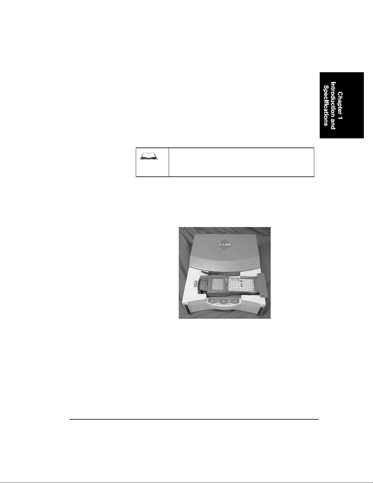
Figure 1-1 2325 In the Cradle of the Vehicle Printer........................................................... 1-1
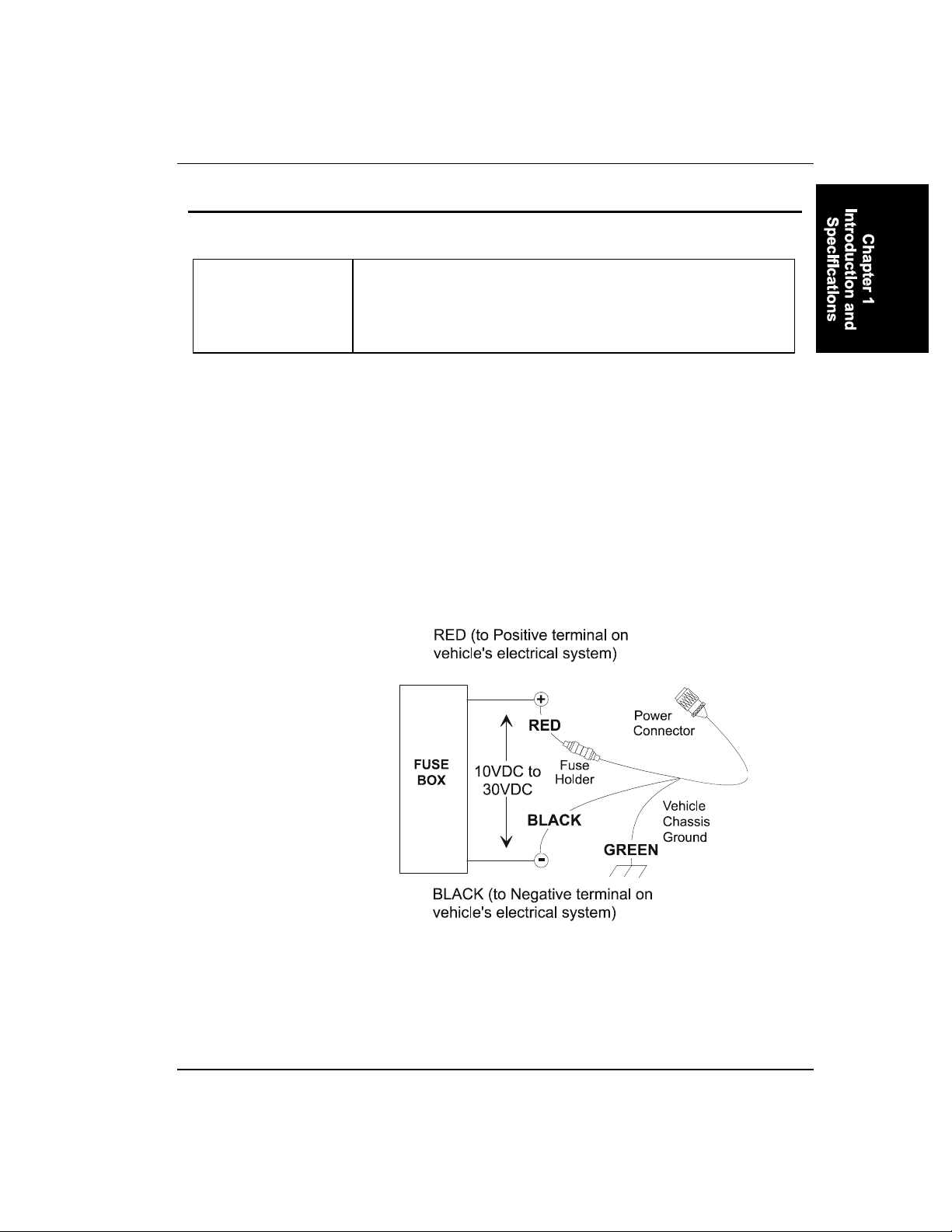
Figure 1-2 Proper Connection of the Vehicle Cable ............................................................1-5
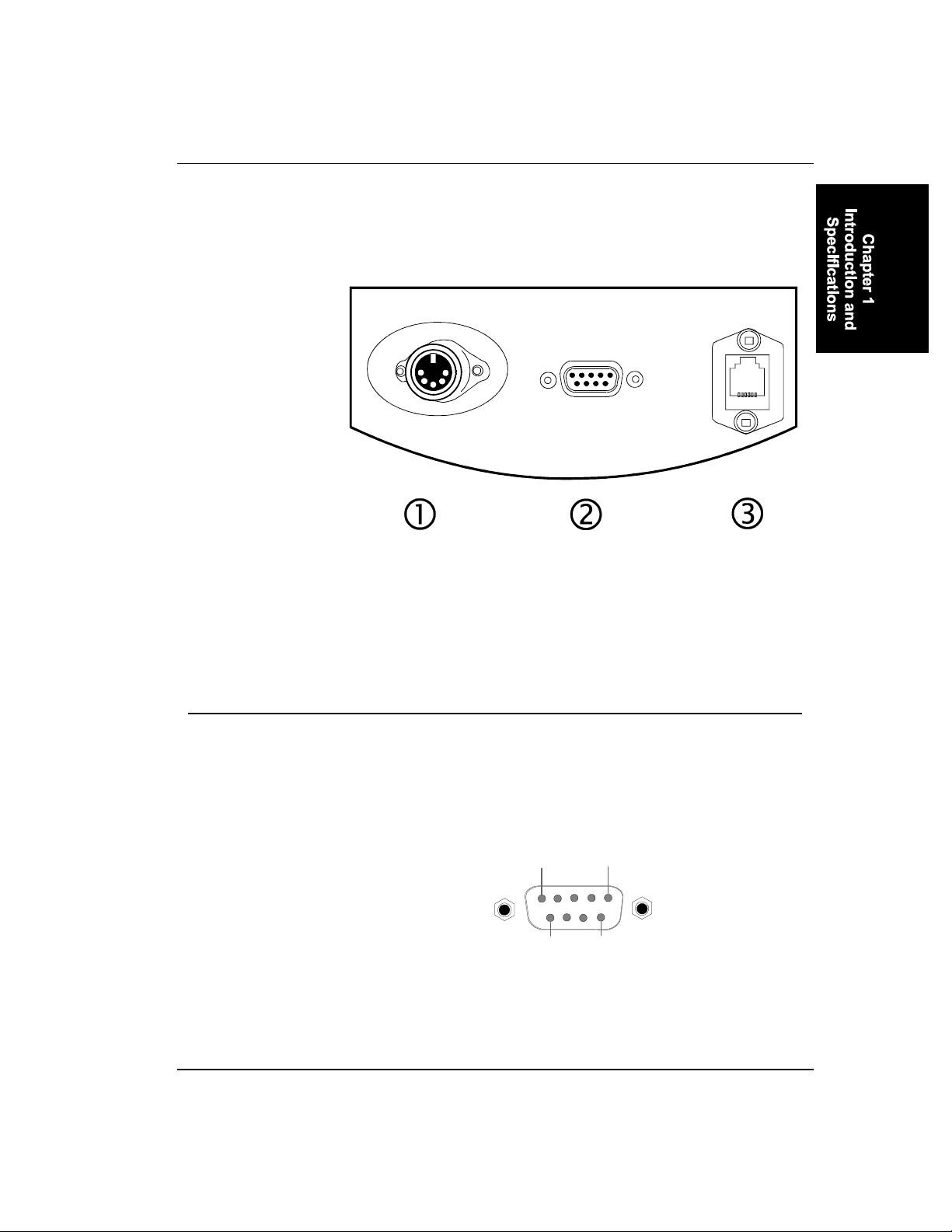
Figure 1-3 Three Connectors on Vehicle Printer .................................................................1-7
Figure 1-4 RS-232 Pinouts...................................................................................................1-7
Figure 1-5 9-Pin RS-232 Description...................................................................................1-8
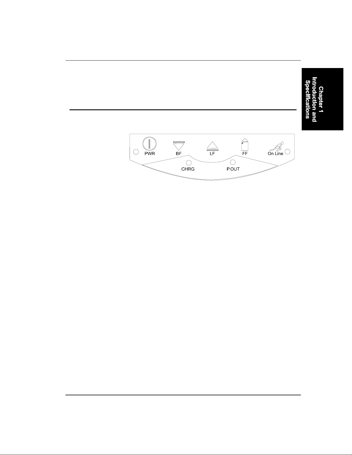
Figure 1-6 Printer Panel Buttons........................................................................................1-11
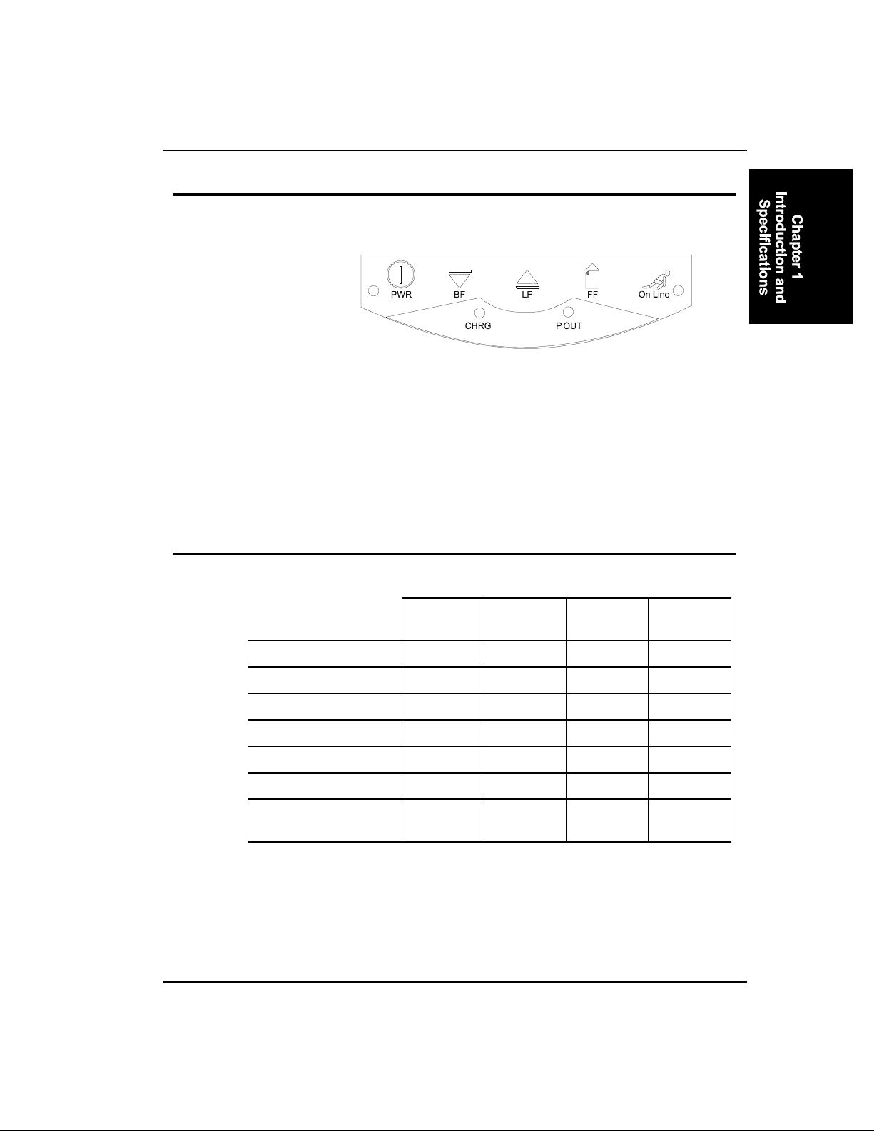
Figure 1-7 Printer Panel Indicators .................................................................................... 1-13
Figure 1-8 Cradle Indicators .............................................................................................. 1-14
E-EQ-2325VPRG-A-ARC 2325 Vehicle Printer Reference Guide
Page 6

iv Table of Contents
2325 Vehicle Printer Reference Guide E-EQ-2325VPRG-A-ARC
Page 7

Table of Contents
CHAPTER 1 INTRODUCTION AND SPECIFICATIONS 1-1
Introduction ........................................................................................ 1-1
About This Guide ........................................................................................1-2
Document Conventions ...............................................................................1-2
Connect Power Supplies ................................................................... 1-3
Physical Installation ....................................................................................1-3
Internal 12V Battery Instruction ...............................................................1-3
Connect the Battery ..................................................................................1-3
Battery Life ...............................................................................................1-4
Vehicle to Battery Connection....................................................................1-5
Fuse Replacement........................................................................................1-6
Connectors ......................................................................................... 1-7
Optional RS-232 Connector .......................................................................1-7
Optional Internal Modem...........................................................................1-8
Specifications and Features.............................................................. 1-9
Printer Keypad.................................................................................. 1-11
Printer Panel Buttons................................................................................1-11
Printer Self Test.........................................................................................1-12
Printer Panel Indicators ...........................................................................1-13
Printer Panel Conditions ..........................................................................1-13
Cradle Indicators.......................................................................................1-14
Configuration.................................................................................... 1-15
Dip Switches...............................................................................................1-15
Default Factory Settings ...........................................................................1-15
Baud Rate Selection ..................................................................................1-16
E-EQ-2325VPRG-A-ARC 2325 Vehicle Printer Reference Guide
Page 8

ii Table of Contents
Illustrations
Figure 1-1 2325 In the Cradle of the Vehicle Printer........................................................... 1-1
Figure 1-2 Proper Connection of the Vehicle Cable ............................................................1-5
Figure 1-3 Three Connectors on Vehicle Printer ................................................................. 1-7
Figure 1-4 RS-232 Pinouts................................................................................................... 1-7
Figure 1-5 9-Pin RS-232 Description................................................................................... 1-8
Figure 1-6 Printer Panel Buttons........................................................................................ 1-11
Figure 1-7 Printer Panel Indicators .................................................................................... 1-13
Figure 1-8 Cradle Indicators .............................................................................................. 1-14
2325 Vehicle Printer Reference Guide E-EQ-2325VPRG-A-ARC
Page 9
Introduction
Chapter 1
Introduction and Specifications
Refer to the 2325 Vehicle Printer Operator’s Guide
(LXE DocID 2325A137OPGD) for operation and
installation information
The portable LXE™ 2325 Vehicle Printer, for use with LXE’s 2325
handheld computers, combines a rugged dot matrix printer with the
charging and storage functions of a storage cradle for the handheld
computer. The printer has an integrated vehicle power supply, integrated
paper tray and 2325 cradle. The unit prints a full 80 columns width at
180 characters per second.
Figure 1-1 2325 In the Cradle of the Vehicle Printer
The built-in computer cradle in the printer safely holds the 2325
handheld computer for both data printing and computer storage and
charges the 2325 battery. The printer operates as a true portable system
powered by its own internal rechargeable battery.
Note: Refer to the next sections for information on the 12V internal
battery and connecting vehicle power to the printer.
E-EQ-2325VPRG-A-ARC 2325 Vehicle Printer Reference Guide
Page 10

1-2 Introduction
About This Guide
Refer to the LXE 2325 Operator’s Guide (LXE DocID
2325A136OPGD) for instructions when operating a 2325 in the 2325
Vehicle Printer.
This guide presents information on the printer, paper, ribbons, printer
settings, indicator lights, charging the battery, care and maintenance,
programming the printer, and supported character sets.
This product contains a Small Sealed Lead-Acid (SSLA) battery.
This battery must be recycled. Disposal of this battery must be in
accordance with local, state, and federal regulations. The State of
Florida “Land Ban” applies to this battery. In Canada, disposal must
be in compliance with Canadian environmental protection laws. For
further information call LXE at 770-449-0154.
Document Conventions
The following conventions are used in this document:
• Bold type and CAPITAL LETTERS are used to identify commands.
• Italics are used for parameters.
• Bullets indicate:
- action items
- lists of alternatives
- lists of required steps that are not necessarily sequential.
• Sequential lists (e.g., those that describe step-by-step procedures)
appear as numbered lists.
2325 Vehicle Printer Reference Guide E-EQ-2325VPRG-A-ARC
Page 11
Connect Power Supplies 1-3
Connect Power Supplies
Physical Installation
The printer is designed to be fully portable. The main criteria for
installation/operation is to ensure that the unit is level so that the
printhead moves from side to side without having to be pulled “uphill”
by the carriage motors.
When mounted within the cab of a vehicle or anywhere else within the
vehicle, care should be taken to ensure that the unit does not move
during acceleration, braking or traversing rough roads. This may be
accomplished by use of straps or a retaining box around the printer.
Excessive vibration and shock can be minimized by using dense foam
padding under and/or around the unit.
It would not be advisable to place the printer in any location where it
could become a lethal projectile in the event of an accident.
Internal 12V Battery Instruction
Important
The LXE 2325 Vehicle Printer is shipped with a disconnected battery.
This method preserves the overall life of the battery as well as maintains
the original charge. Make sure to connect the battery before using the
printer. The battery is a 12V DC lead acid gel battery, Model PP12V2
manufactured by GS Battery-Canada.
Connect the Battery
1. Open and remove the printer cover (see section titled “Opening the
Printer”).
2. Open the printer mechanism using the release lever (see section
titled “Paper, Loading Paper”).
3. Flip up the levers on both tractor feed assemblies (see section titled
“Paper, Loading Paper”).
4. Using a Phillips screwdriver, loosen (DO NOT REMOVE) the two
screws on each end of the battery hold down bar (battery bar screws
E-EQ-2325VPRG-A-ARC 2325 Vehicle Printer Reference Guide
Page 12

1-4 Connect Power Supplies
can be seen through the two holes in the printer mechanism base
plate). The battery bar is located directly below the printer
mechanism base plate.
5. Slide the battery out from its compartment to access the battery
terminals (to slide the battery out, tilt the printer while slightly
lifting on the battery).
6. Remove tape on wires as well as the red tape on the terminals and
connect the red wire to the red terminal on the battery and the black
wire to the black terminal - make sure the wires stay underneath the
hold down bar.
7. Slide the battery (lettering side down) underneath the hold down bar
by tilting it forward.
8. Tighten the two screws. Hint: Load the paper in the printer after
this step.
9. Flip down the two levers on the tractor feed assemblies.
10. Lower the printer mechanism.
11. Close the cover.
The printer is now ready to use.
Battery Life
In order to maintain the life of the 12V gel battery in the printer, one of
two options must be followed:
1. The printer is turned off and left plugged into a charger when not in
use.
2. The battery is disconnected if the printer is to be unused for more
than four weeks.
2325 Vehicle Printer Reference Guide E-EQ-2325VPRG-A-ARC
Page 13
Connect Power Supplies 1-5
Vehicle to Battery Connection
Important This equipment is designed for Vehicle Use Only. Any other use is
at the owner’s risk and responsibility.
Equipment is designed to use 10 to 30 volt DC power source only.
The printer should receive a full charge on a daily basis. The battery is
fully charged when the green LED turns off.
The printer is designed for use with any DC power source within the
range of 10 V to 30 V. When connected to a power source that falls
within this range and can source the proper amount of current, the
printer battery will be properly charged and will maintain its charge
under normal usage.
It is recommended that the vehicle cable be connected to an unswitched
outlet on the vehicle’s fuse box, or directly to the vehicle battery. This
connection method reduces the chance of interference from the vehicle’s
charging system and prolongs the life of the printer’s internal 12V DC
Lead acid gel battery.
Figure 1-2 Proper Connection of the Vehicle Cable
The printer chassis (green wire) is isolated from the printer electronic
ground. Therefore, the printer can be used with positive or negative
ground vehicle systems.
E-EQ-2325VPRG-A-ARC 2325 Vehicle Printer Reference Guide
Page 14
1-6 Connect Power Supplies
When the printer is connected to an unswitched outlet on the fuse box
the printer will always receive a charge from the vehicle battery. If the
unit is left turned on for extended periods of time the unit could drain the
vehicle battery.
If the printer is connected to a switched outlet on the fuse box the printer
will only charge when the vehicle is on. This will eliminate the problem
of draining the vehicle battery; however it may place additional load on
the internal battery of the printer should the vehicle be run for short
periods. The printer should receive a full charge on a daily basis. The
unit is fully charged when the green CHARGING indicator light turns
off. The printer must be connected to an external source (vehicle or
external power supply) to ensure that the battery is properly charged.
Fuse Replacement
The unit uses a 250V, 3A Fast Blow, high current interrupting rating
fuse that is externally accessible and user replaceable. Should it need
replacement, replace with same size, rating and type of fuse -- Littelfuse
part number 312-003.
Internal Fuse Replacement:
The internal fuses F1 and F2 are rated at
F1: 250V 4 Amps Slow Blow
F2: 250V 3 Amps Fast Blow
Caution:
For continued protection against risk of fire, replace
only with the same type and rating of fuse.
2325 Vehicle Printer Reference Guide E-EQ-2325VPRG-A-ARC
Page 15
Connectors 1-7
Connectors
Figure 1-3 Three Connectors on Vehicle Printer
1 Power
2 RS-232 (Optional) Connector
3 Internal Modem (Optional) Connector
Optional RS-232 Connector
RS-232 Connection is made through an RS-232 Connector. The
connector is an industry-standard RS-232. The connector includes a
PC/AT standard 9-pin “D” male connector with pin 9 capable of
supplying 5 VDC at 200mA (max) for an external barcode scanner.
(RJ-45)
Pin 1 Pin 5
Pin 6 Pin 9
Figure 1-4 RS-232 Pinouts
E-EQ-2325VPRG-A-ARC 2325 Vehicle Printer Reference Guide
Page 16

1-8 Connectors
PIN SIGNAL DESCRIPTION
1 DCD Data Carrier Detect - Input
2 RXD Receive Data - Input
3 TXD Transmit Data - Output
4 DTR Data Terminal Ready - Output
5 GND Signal/Power Ground
6 DSR Data Set Ready - Input
7 RTS Request to Send - Input
8 CTS Clear To Send - Input
9 RI Ring Indicator - Input (Default)
Figure 1-5 9-Pin RS-232 Description
Optional Internal Modem
Note: Chapter 4 “Software Controlled Universal Serial Switch
(SCUSS)” only applies when a modem board is installed in the
vehicle printer.
Plug one end of the telephone cord (four conductor flat cable) into the 6pin RJ-45 connector and the other end into an analog telephone wall
jack.
The modem supports the AT Command set with extensions and can
operate with industry standard communication software.
2325 Vehicle Printer Reference Guide E-EQ-2325VPRG-A-ARC
Page 17

Specifications and Features 1-9
Specifications and Features
Suggested Paper
Suggested Ribbons
Integrated 2325
Computer Cradle
Printer Engine Performance
• Print Speed • 180 characters per second
• Print Modes • Normal Near Letter Quality (NLQ) at
Printer Battery
• Single Charge
Performance
• Battery Life • 720 charge/discharge cycles
• Recharge Time • 5 hours maximum
• Use forms such as 3-part 8.5” x 11”
pin feed paper NCR product
#951S23
• Use Brother product #UM0117500
(or equivalent)
• Fully charges 2325 battery in
7 hours
• Trickle charge maintains full charge
80 characters per line
• Bold NLQ at 40 characters per
second
• Condensed NLQ at 132 characters
per line
• Graphics at reduced speed
• 100 full page reports on a full charge
(about 3100 full 80 character lines)
Paper Tray Capacity
Indicators
User Controls
E-EQ-2325VPRG-A-ARC 2325 Vehicle Printer Reference Guide
• 250 single fan fold sheets/75 three
part forms
• 2325 communications active
• 2325 battery charging
• Printer power on
• Printer battery charging
• Printer on-line
• Printer Power On/Off
• Printer On-line/Off-line
• Line Feed
• Back Space
• Form Feed
Page 18

1-10 Specifications and Features
Physical Dimensions
• 18”L x 12.875”W x 5.25”H
45.7cm L x 32.7cm W x 13.3cm H
• 10.8 lbs (4.89 kilograms) with battery
Weight
without paper
• 12.7 lbs (5.76 kilograms) with battery
and full paper tray
• 14.5 lbs (6.57 kilograms) with
battery, full paper tray, and 2325
handheld computer
Temperature Range
• -10°C to 40°C, -14°F to 104°F
15% to 85% humidity, noncondensing
• -30°C to 70°C, -22°F to 160°F
5% to 95% humidity, non-condensing
storage
Power Input
• 10 - 30 VDC at 3 amps maximum
Requirements
Options
• Spare battery
• Spare ribbons
2325 Vehicle Printer Reference Guide E-EQ-2325VPRG-A-ARC
Page 19
Printer Keypad 1-11
Printer Keypad
Printer Panel Buttons
Figure 1-6 Printer Panel Buttons
There are five buttons on the keypad:
• PWR (POWER) - used to turn the printer ON and OFF
• BF (BACK FEED) - used to feed the paper back one line at a
time (also used for NLQ self test)
• LF (LINE FEED) - used to feed the paper, one line at a time
(also used for DRAFT self test)
• FF (FORM FEED) - used to feed the paper one form length
with respect to top of form
• On-Line - used to toggle the printer between online and offline
(also used to set Low Temperature Mode).
For Continuous Feed, hold down the LINE FEED and BACK FEED
buttons. The printer must be off-line in order for LINE FEED, BACK
FEED and FORM FEED to function.
Top of Form is set when the printer is turned on. If the printer is turned
on and the paper is half way out of the printer, it will set that point on the
page as top of form. Ensure that the printer is off-line and adjust the
paper position with line feed or back feed to the appropriate position on
the page. The printer must then be turned OFF and back ON. This will
set the top of form to the correct position.
E-EQ-2325VPRG-A-ARC 2325 Vehicle Printer Reference Guide
Page 20

1-12 Printer Keypad
Printer Self Test
To determine if the print mechanism is functioning properly:
1. Turn the printer OFF.
2. Turn the printer ON while holding down one of the following
buttons:
BACK FEED for NLQ test
LINE FEED for DRAFT test.
2325 Vehicle Printer Reference Guide E-EQ-2325VPRG-A-ARC
Page 21
Printer Keypad 1-13
Printer Panel Indicators
Figure 1-7 Printer Panel Indicators
There are four indicators on the printer:
• POWER - red
• CHARGING - green
• PAPER OUT - red
• ONLINE - red.
Printer Panel Conditions
Power
On line
Paper Empty
Charging
Fully charged
Power supply error
ROM/RAM error
Carriage position
error
Online
Red
Light on Light on
Light on Light on
Light on
Light off
Flashing
Flashing Flashing Flashing
Flashing Flashing Flashing
Red
Charging
Green
Paper Out
Red
E-EQ-2325VPRG-A-ARC 2325 Vehicle Printer Reference Guide
Page 22

1-14 Printer Keypad
Cradle Indicators
Figure 1-8 Cradle Indicators
CHG Green. The battery is charging. When battery is fully
charged, the light goes out.
DATA Green. The 2325 is sending data to the printer. When
transmission is complete, the light goes out.
2325 Vehicle Printer Reference Guide E-EQ-2325VPRG-A-ARC
Page 23
Configuration 1-15
Configuration
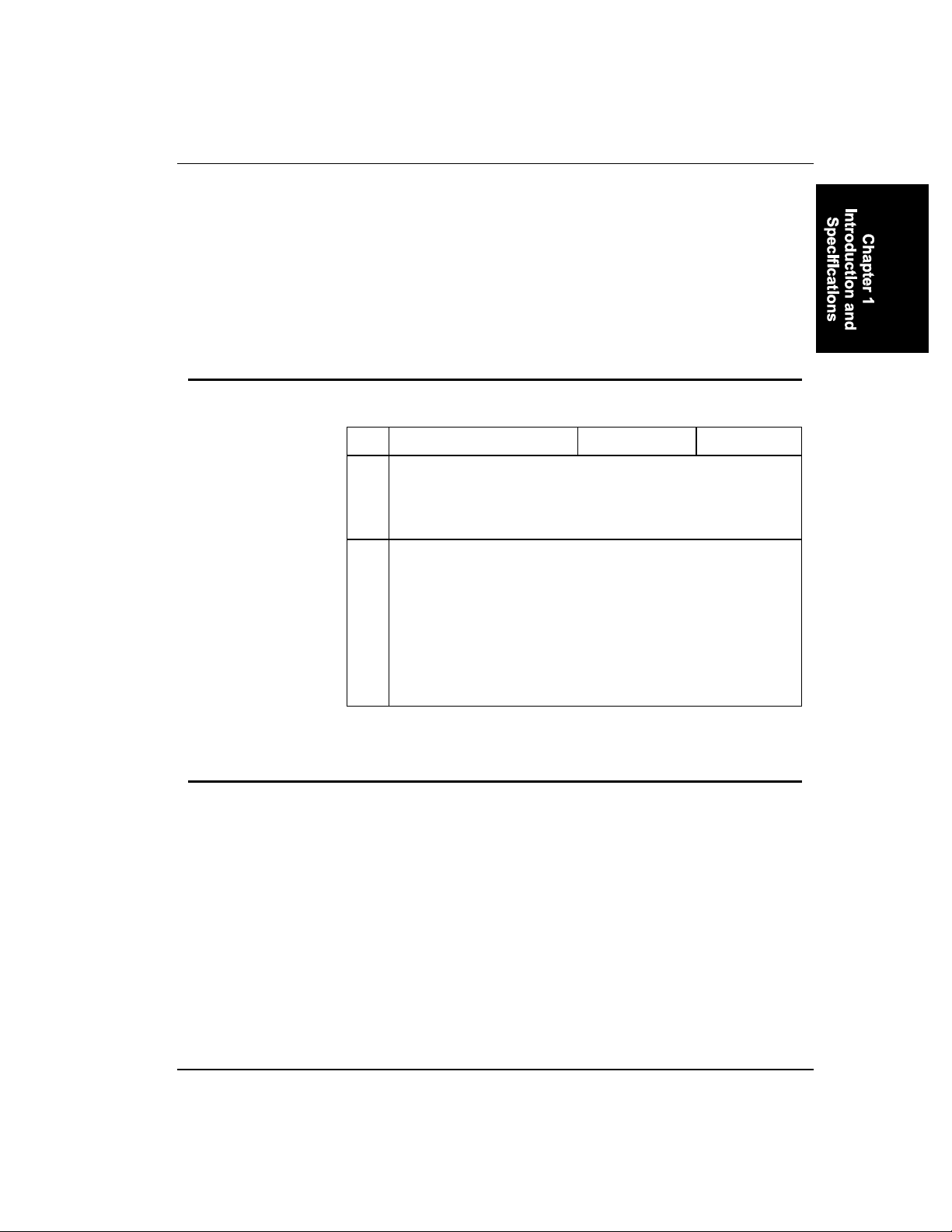
The printer must be configured to match the parameters used by the
software which runs on the 2325 hand-held computer. The configuration
is set by eight dip switches located on top of the printer mechanism.
Dip Switches
# Function ON OFF
1
Baud Rate Selection See Below
2
3
Parity Check Yes
4
Parity Check Even
5
No
Odd
Character Code Level 7 bits
6
Handshaking Protocol
7
Auto Line Feed
8
Default Factory Settings
BAUD RATE
PARITY CHECK
PARITY
CHARACTER CODE LEVEL
HANDSHAKING
AUTO LINE FEED
X-ON/X-OFF
No
CR=CR
9600 bps
No
Odd
8 Bits
X-ON/X-OFF
NO (CR=CR)
8 bits
N/A
Yes
CR=CR+LF
E-EQ-2325VPRG-A-ARC 2325 Vehicle Printer Reference Guide
Page 24
1-16 Configuration
Baud Rate Selection
Select # Setting
1
2
3
Baud Rate
OFF
OFF
OFF
9600
ON OFF ON OFF ON OFF ON
OFF ON ON OFF OFF ON ON
OFF OFF OFF ON ON ON ON
4800 2400 1200 600 300 150 110
2325 Vehicle Printer Reference Guide E-EQ-2325VPRG-A-ARC
Page 25

Table of Contents
CHAPTER 2 PROGRAMMING THE PRINTER 2-1
Defaults ............................................................................................... 2-1
Control Commands ............................................................................2-2
Command Summary List...........................................................................2-2
Command Descriptions..................................................................... 2-6
Printer Operation Control......................................................................... 2-6
Initialization............................................................................................. 2-6
ESC [ K Initialize Printer ......................................................................... 2-6
Low-Temperature Operation Mode......................................................... 2-9
ESC [ L Set/Cancel Low-Temperature Operation Mode ......................... 2-9
Data Control ..........................................................................................2-10
DC1 Select Printer .................................................................................. 2-10
ESC Q Deselect Printer .......................................................................... 2-10
CAN Clear Printer Buffer....................................................................... 2-10
Horizontal Motion ................................................................................. 2-11
BS Backspace ......................................................................................... 2-11
CR Carriage Return ................................................................................ 2-11
Carriage Return Control ........................................................................2-12
ESC 5 Set/Cancel Auto Line Feed ......................................................... 2-12
Print Quality ..........................................................................................2-13
ESC x Select Print Quality ..................................................................... 2-13
Print Direction .......................................................................................2-14
ESC < Set Left-to-Right Unidirectional Printing................................... 2-14
ESC U Set/Cancel Unidirectional Printing ............................................ 2-14
Paper Empty Sensor Control .................................................................2-15
ESC 8 Disable Paper Empty Sensor ....................................................... 2-15
ESC 9 Enable Paper Empty Sensor ........................................................ 2-15
Paper Feed Control .................................................................................. 2-16
Vertical Feed.......................................................................................... 2-16
LF Line Feed .......................................................................................... 2-16
FF Form Feed ......................................................................................... 2-16
ESC ] Reverse Line Feed........................................................................ 2-16
ESC J Execute n/216” Line Spacing ...................................................... 2-17
E-EQ-2325VPRG-A-ARC 2325 Vehicle Printer Reference Guide
Page 26

2-ii Table of Contents
Skip-Over Perforation............................................................................2-18
ESC N Activate Skip-Over Perforation Function................................... 2-18
ESC O Deactivate Skip-Over Perforation Function ............................... 2-18
Line Spacing ..........................................................................................2-19
ESC 0 Set 1/8” Line Spacing.................................................................. 2-19
ESC 1 Set 7/72” Line Spacing................................................................ 2-19
ESC 2 Activate Line Spacing Set by ESC A.......................................... 2-19
ESC 3 Set n/216” Line Spacing.............................................................. 2-20
ESC A Set n/72” Line Spacing............................................................... 2-20
Page Format Control................................................................................2-21
Page Length............................................................................................2-21
ESC C Set Page Length (Lines or Inches).............................................. 2-21
Margins ..................................................................................................2-22
ESC 4 Set Top-of -Form Position........................................................... 2-22
ESC X Set Right and Left Margins ........................................................ 2-22
Tab .........................................................................................................2-24
HT Horizontal Tab.................................................................................. 2-24
VT Vertical Tab...................................................................................... 2-24
ESC B Set Vertical Tab Stops ................................................................ 2-24
ESC D Set Horizontal Tab Stops............................................................ 2-25
ESC R Restore to Default Tab Settings.................................................. 2-25
Character Control ............................................................................ 2-26
Font Selection ............................................................................................2-26
ESC k Select NLQ Font.......................................................................... 2-26
Character Pitch .........................................................................................2-27
DC2 Set Pica Pitch ................................................................................. 2-27
ESC : Set Elite Pitch ............................................................................... 2-27
ESC P Set/Cancel Proportional Spacing ................................................ 2-27
ESC 6 Select Character Set 2 ................................................................. 2-28
ESC 7 Select Character Set 1 ................................................................. 2-28
ESC \ Print Characters from All-Character Code Set............................. 2-28
ESC ^ Print One Character from All-character Code Set....................... 2-28
Character Style .........................................................................................2-30
SO Set Double-width Character Mode (One Line Only) ....................... 2-30
SI Set Condensed Character Mode ........................................................ 2-30
DC4 Cancel Double-Width Character Mode Set by SO ........................ 2-30
ESC ! Change Print Mode Parameters.................................................... 2-30
ESC - Activate/Deactivate Underline Function...................................... 2-31
ESC E Set Emphasized Character Mode ................................................ 2-32
ESC F Cancel Emphasized Character Mode .......................................... 2-32
2325 Vehicle Printer Reference Guide E-EQ-2325VPRG-A-ARC
Page 27

Table of Contents 2-iii
ESC G Set Double-Strike Character Mode ............................................ 2-32
ESC H Cancel Double-Strike Character Mode ...................................... 2-33
ESC S Set Super-/Subscript Print Mode ................................................ 2-33
ESC T Cancel Super-/Subscript Print Mode .......................................... 2-33
ESC W Set/Cancel Double-Width Character Mode............................... 2-33
ESC [ @ Set Double-Height/Double-Width Character Mode................ 2-34
ESC _ Activate/Deactivate Overline Function....................................... 2-36
Miscellaneous............................................................................................ 2-37
ESC I Select Print Mode......................................................................... 2-37
Bit Image Control ............................................................................. 2-38
Creating 8-Pin Bit Images .......................................................................2-38
ESC * Select Bit Image Mode................................................................ 2-38
ESC K Set Single-density Bit Image Mode............................................ 2-41
ESC L Set Double-Density Bit Image Mode.......................................... 2-41
ESC Y Set Double-Speed and Double-Density Bit Image Mode........... 2-42
ESC Z Set Quadruple-Density Bit Image Mode..................................... 2-42
Density Change......................................................................................... 2-43
ESC ? Change Bit Image Density........................................................... 2-43
ESC r Select International Character Set ............................................... 2-44
E-EQ-2325VPRG-A-ARC 2325 Vehicle Printer Reference Guide
Page 28

2-iv Table of Contents
2325 Vehicle Printer Reference Guide E-EQ-2325VPRG-A-ARC
Page 29

Defaults
Chapter 2
Programming the Printer
When powered on or reset, the printer automatically selects the default
settings listed below:
Item Default settings
Page length 11 inches
Line feed pitch 1/6 inch
Print quality and pitch Draft, pica
NLQ font Prestige
Character set table Character set 2 (USA)
International character set USA
VT setting Cleared
HT setting Every 8 characters
Right margin At the 80th column (right end)
Left margin At the 1st column (left end)
Skip-over perforation Canceled
Print attributes *1 Canceled
Auto CR Canceled
Auto line feed Setting by DIP switch
Print direction
• Normal printing
• Bit image printing*2
• NLQ or graphic character printing*2
Bi-directional
Unidirectional from left to right
Unidirectional
*1 Print attributes include the condensed, underline, overline, italic,
emphasized, double-strike, super/subscript, double-width, doubleheight/double-width, and proportional prints.
*2 Bit images, NLQ, and graphic characters may be printed bidirectionally by
modifying parameter p2 (bit 5) of ESC [ K command.
E-EQ-2325VPRG-A-ARC 2325 Vehicle Printer Reference Guide
Page 30
2-2 Control Commands - Command Summary List
Control Commands
Command Summary List
Command Function Value in Hex.
BS Backspace 08
HT Horizontal Tab 09
LF Line Feed 0A
VT Vertical Tab 0B
FF Form Feed 0C
CR Carriage Return 0D
SO (Shift-out) Set Double-width Character
Mode (One line only)
SI (Shift-in) Set Condensed Character
Mode
DC1 (Device Control 1) Select Printer 11
DC2 (Device Control 2) Select Pica Pitch 12
DC4 (Device Control 4) Cancel Double-width
Character Mode Set by SO
CAN Clear Printer Buffer 18
ESC ! n Change Print Mode Parameters 1B 21 n
ESC * m n1 n2 data Select Bit Image Mode 1B 2A m n1 n2 data
ESC - n Activate/Deactivate Underline
Function
0E
0F
14
1B 2D n
2325 Vehicle Printer Reference Guide E-EQ-2325VPRG-A-ARC
Page 31
Control Commands - Command Summary List 2-3
Command Function Value in Hex.
ESC 0 Set 1/8” Line Spacing 1B 30
ESC 1 Set 7/72” Line Spacing 1B 31
ESC 2 Activate Line Spacing Set by
1B 32
ESC A
ESC 3 n Set n/216” Line Spacing 1B 33 n
ESC 4 Set Top-of-form Position 1B 34
ESC 5 n Set/Cancel Auto Line Feed 1B 35 n
ESC 6 Select Character Set 2 1B 36
ESC 7 Select Character Set 1 1B 37
ESC 8 Disable Paper Empty Sensor 1B 38
ESC 9 Enable Paper Empty Sensor 1B 39
ESC : Set Elite Pitch 1B 3A
ESC < Set Left-to right Unidirectional
1B 3C
Printing (One line only)
ESC ? n m Change Bit Image Density 1B 3F n m
ESC A n Set n/72” Line Spacing 1B 41 n
ESC B n1 ...n64 NUL Set Vertical Tab Stops 1B 42 n1 ...n64 00
ESC C n Set Page Length (No. of lines) 1B 43 n
ESC C NUL n Set Page Length (In inches) 1B 43 00 n
ESC D n1 ...n28 NUL Set Horizontal Tab Stops 1B 44 n1 ...n28 00
ESC E Set Emphasized Character
1B 45
Mode
ESC F Cancel Emphasized Character
1B 46
Mode
E-EQ-2325VPRG-A-ARC 2325 Vehicle Printer Reference Guide
Page 32
2-4 Control Commands - Command Summary List
Command Function Value in Hex.
ESC G Set Double-strike Character
1B 47
Mode
ESC H Cancel Double-strike
1B 48
Character Mode
ESC I n Select Print Mode 1B 49 n
ESC J n Execute n/216” Line Spacing 1B 4A n
ESC K n1 n2 data Set Single-density Bit Image
1B 4B n1 n2 data
Mode
ESC L n1 n2 data Set Double-density Bit Image
1B 4C n1 n2 data
Mode
ESC N n Activate Skip-over Perforation
1B 4E n
Function
ESC O Deactivate Skip-over
1B 4F
Perforation Function
ESC P n Set/Cancel Proportional
1B 50 n
Spacing
ESC Q n Deselect Printer 1B 51 n
ESC R Restore to Default Tab
1B 52
Settings
ESC S n Set Super-/Subscript Print
1B 53 n
Mode
ESC T Cancel Super-/Subscript Print
1B 54
Mode
ESC U n Set/Cancel Unidirectional
1B 55 n
Printing
ESC W n Set/Cancel Double-width
1B 57 n
Character Mode
ESC X n1 n2 Set Right and Left Margins 1B 58 n1 n2
2325 Vehicle Printer Reference Guide E-EQ-2325VPRG-A-ARC
Page 33
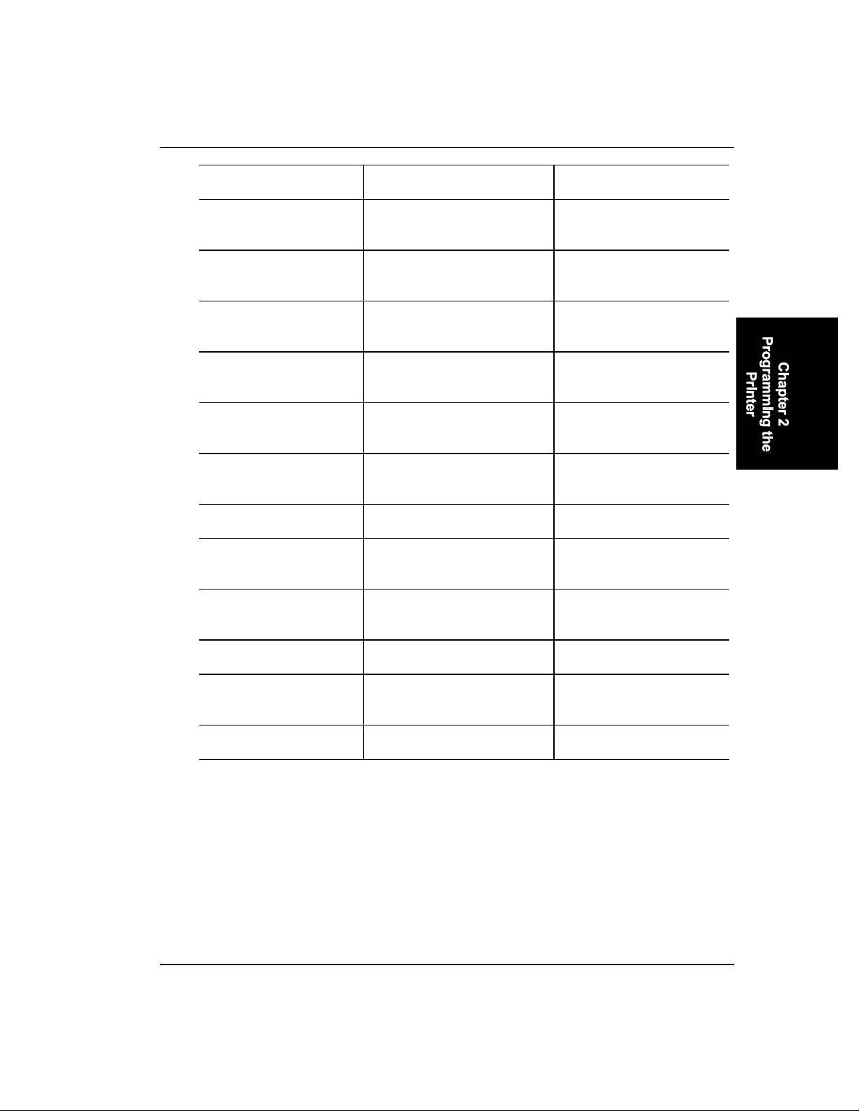
Control Commands - Command Summary List 2-5
Command Function Value in Hex.
ESC Y n1 n2 data Set Double-speed and Double-
1B 59 n1 n2 data
density Bit Image Mode
ESC Z n1 n2 data Set Quadruple-density Bit
1B 5A n1 n2 data
Image Mode
ESC [@ n1 n2 m1 m2 m3
m4
ESC [ K n1 n2 init id p1
p2
ESC [ L n1 n2 m Set/Cancel Low-temperature
Set Double-height/Doublewidth Character Mode
1B 5B 40 n1 n2 m1 m2 m3
m4
Initialize Printer 1B 5B 4B n1 n2 init id p1
p2
1B 5B 4C n1 n2 m
Operation Mode
ESC \ n1 n2 Print Characters from All-
1B 5C n1 n2
character Code Set
ESC ] Reverse Line Feed 1B 5D
ESC ^ Print One Character from All-
1B 5E
character Code Set
ESC _ n Activate/Deactivate Overline
1B 5F n
Function
ESC k n Select NLQ Font 1B 6B n
ESC r n Select International Character
1B 72 n
Set
ESC x n Select Print Quality 1B 78 n
E-EQ-2325VPRG-A-ARC 2325 Vehicle Printer Reference Guide
Page 34

2-6 Command Descriptions - Printer Operation Control
Command Descriptions
Printer Operation Control
Initialization
ESC [ K Initialize Printer
Format:
ESC [ K n1 n2 init id p1 p2
n1 : 01H, 03H, or 04H
n2 : 00H
init: 00H, 01H, 04H, 05H, FEH, or FFH
id: 03H
p1 : 00H ≤ p1 ≤ FFH
p2 : 00H ≤ p2 ≤ FFH
Dec.
27 91 75 n1 n2 init id p1 p2
Hex.
1B 5B 4B n1 n2 init id p1 p2
Function
Initializes the printer after printing the data stored in the print buffer.
However, this command does not clear the input buffer.
n1 and n2 specify the number of the following parameter bytes (init, id,
p1 and p2 ) so that the (n1 + n2 x 256) number of data bytes are
accepted as parameters of this command. Up to four bytes of data can
follow this command as init, id, p1 and p2 . The printer will be
initialized according to these parameters.
n1 = 01H: The printer is initialized according to init.
n1 = 03H: The printer is initialized according to init and p1 .
2325 Vehicle Printer Reference Guide E-EQ-2325VPRG-A-ARC
Page 35
Command Descriptions - Printer Operation Control 2-7
n1 = 04H: The printer is initialized according to init, p1 and
p2 .
“init” is any number from 00H through 05H, or FEH or FFH that
specifies how the printer is initialized.
init = 00H:
The printer is initialized according to the parameters of this
command. The code page setting is not reset (even if it is
specified by p2 ).
init = 01H, 05H, FEH or FFH:
The printer is initialized according to the parameters of this
command
init = 04H:
The printer is initialized according to the parameters of this
command. The USA character set (USA, Multilingual) is
always selected.
“id” is always 3.
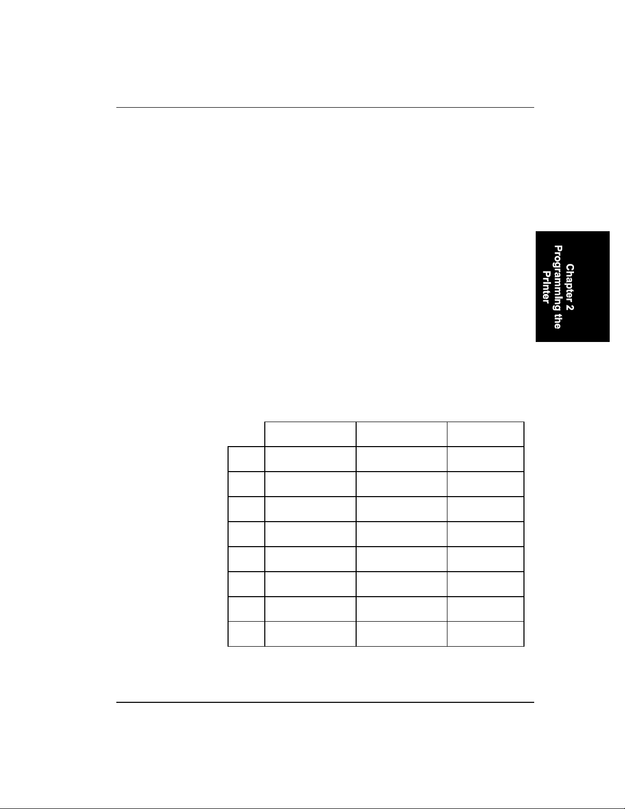
The printer is initialized according to parameters p1 and p2 . They are
defined as follows:
p1
Bit Function 0 1
7 p1 Accept p1 Ignore p1
6 Not used. --- ---
5 Not used. --- ---
4 AUTO CR OFF ON
3 AUTO LF OFF ON
2 Page length 11” 12”
1 Zero font Unslashed Slashed
0 Select character set Character set 1 Character set 2
E-EQ-2325VPRG-A-ARC 2325 Vehicle Printer Reference Guide
Page 36
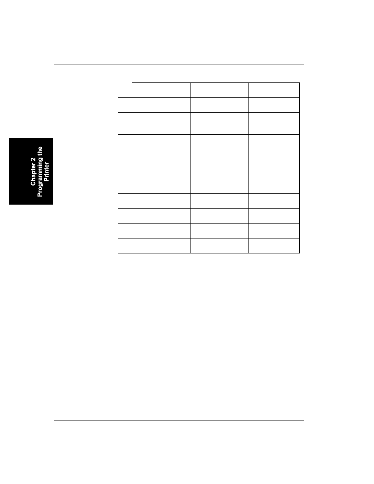
2-8 Command Descriptions - Printer Operation Control
p2
Bit Function 0 1
7 p2 Accept p2 Ignore p2
6 USA or multilingual
character set
5 Printing direction for
USA character set Multilingual
character set
Bi-directional Unidirectional
bit images, NLQ,
and graphic
characters
4 20 cpi Condensed
elite
Valid Condensed
elite
Invalid Elite
3 NLQ font selection Prestige ---
2 FF code (at TOF) Valid Invalid
1 Not used. --- ---
0 Not used. --- ---
Each flag bit 7 of parameters p1 and p2 is used to accept or ignore the
settings of that parameter, respectively. If bit 7 is 1, the settings of that
parameter are ignored and the printer is initialized according to the
default settings. If bit 7 is 0, the printer is initialized according to the
settings of that parameter.
If bit 2 of p2 is 1 (invalid FF code), the FF code received at the top-ofform (TOF) position is ignored.
2325 Vehicle Printer Reference Guide E-EQ-2325VPRG-A-ARC
Page 37

Command Descriptions - Printer Operation Control 2-9
LowTemperature
Operation Mode
ESC [ L Set/Cancel Low-Temperature Operation Mode
Format
ESC [ L n1 n2 m
n1 = 01H
n2 = 00H
m = 00H: Cancel low-temperature operation mode.
= 01H: Set low-temperature operation mode.
Dec. 27 91 76 n1 n2 m
Hex. 1B 5B 4C n1 n2 m
Function
Sets or cancels low-temperature operation mode according to m as
above. A specification of 01H for m allows the printer to operate in low-
temperature environments. The low-temperature operation mode differs
from the ordinary mode in these ways:
• The printer double strikes all of the print data in unidirectional print
mode.
• Lower carriage travel speed: In the draft mode, the print speed is
reduced from 150 cps to 75 cps. In the NLQ mode, the carriage
returning speed for the 2
half of that in the ordinary mode (that is, half of the travel speed in
the draft mode.) The carriage travel speed for bi-directional logic
seeking print is half of that in the ordinary mode.
• The paper feeding speed is half of that in the ordinary mode.
If the printer receives this command during the continuous printing
operation, the command may take effect, for one or two lines ahead of it.
If the (n2 x 256 + n1 ) > 1, this command is effective while the printer
ignores the surplus data.
If the (n2 x 256 + n1 ) = 1, or if a specification for m is 00H or 01H, the
printer ignores this command.
E-EQ-2325VPRG-A-ARC 2325 Vehicle Printer Reference Guide
nd
pass following the 1st pass is reduced to
Page 38

2-10 Command Descriptions - Printer Operation Control
Data Control
DC1 Select Printer
Format
DC1
Dec. 17
Hex. 11
Function
Takes the printer on-line so that the printer can accept commands and
print data. This command is valid only when the printer has been
selected by an ESC Q command.
ESC Q Deselect Printer
Format
ESC Q n
n = 03H or 16H
Dec. 27 81 n
Hex. 1B 51 n
Function
Takes the printer off-line so that the printer cannot receive commands or
print data until it receives a DC1 command or the ON/OFF LINE switch
is pressed twice.
CAN Clear Printer Buffer
Format
CAN
Dec. 24
Hex. 18
Function
Clears the print data stored in the image buffer. All of the control
commands except for BS, HT, and SO remain unaffected.
2325 Vehicle Printer Reference Guide E-EQ-2325VPRG-A-ARC
Page 39

Command Descriptions - Printer Operation Control 2-11
Horizontal Motion
BS Backspace
Format
BS
Dec. 8
Hex. 08
Function
Moves the print position horizontally one character to the left.
CR Carriage Return
Format
CR
Dec. 13
Hex. 0D
Function
Prints the data in the buffer and returns the print position to the left
margin. If the auto line feed (LF) function is enabled by ESC 5 1
command, a line feed automatically accompanies a carriage return.
E-EQ-2325VPRG-A-ARC 2325 Vehicle Printer Reference Guide
Page 40

2-12 Command Descriptions - Printer Operation Control
Carriage Return Control
ESC 5 Set/Cancel Auto Line Feed
Format
ESC 5 n
n = 00H or 30H: CR = CR
n = 01H or 31H: CR = CR + LF
Dec. 27 53 n
Hex. 1B 35 n
Function
The automatic line feed function is enabled or disabled by n. If n is 01H
or 31H, the printer prints data stored in the buffer and performs a
carriage return plus a line feed, in response to each CR command. If n is
00H or 30H, the printer prints data in the buffer and performs a carriage
return with no line feed.
2325 Vehicle Printer Reference Guide E-EQ-2325VPRG-A-ARC
Page 41

Command Descriptions - Printer Operation Control 2-13
Print Quality
ESC x Select Print Quality
Format
ESC x n
n = 00H or 30H: Draft mode
n = 01H or 31H: NLQ mode
Dec. 27 120 n
Hex. 1B 78 n
Function
Selects the draft or near-letter quality (NLQ) mode with n as above.
E-EQ-2325VPRG-A-ARC 2325 Vehicle Printer Reference Guide
Page 42

2-14 Command Descriptions - Printer Operation Control
Print Direction
ESC < Set Left-to-Right Unidirectional Printing
Format
ESC <
Dec. 27 60
Hex. 1B 3C
Function
Sets the unidirectional printing from left to right for one line only.
ESC U Set/Cancel Unidirectional Printing
Format
ESC U n
n = 00H or 30H: Bi-directional printing (Default setting)
n = 01H or 31H: Unidirectional printing
Dec. 27 85 n
Hex. 1B 55 n
Function
Sets the bi-directional or unidirectional printing with n as above. A
specification of 00H or 30H for n produces bi-directional printing; 01H
or 31H for n, unidirectional printing from left to right. If the printer
receives this command halfway on a line, the setting takes effect on that
line and the following lines.
2325 Vehicle Printer Reference Guide E-EQ-2325VPRG-A-ARC
Page 43

Command Descriptions - Printer Operation Control 2-15
Paper Empty Sensor Control
ESC 8 Disable Paper Empty Sensor
Format
ESC 8
Dec. 27 56
Hex. 1B 38
Function
Disables the paper empty sensor. Even if the paper empty sensor detects
the paper empty state, the printer does not signal it so as to continue
printing. The ESC 9 and ESC [ K cancel this command setting.
ESC 9 Enable Paper Empty Sensor
Format
ESC 9
Dec. 27 57
Hex. 1B 39
Function
Enables the paper empty sensor. If the paper empty sensor detects the
paper empty state, the printer goes off-line. To resume printing, load
paper and press the ON/OFF LINE switch. This command setting is a
default.
E-EQ-2325VPRG-A-ARC 2325 Vehicle Printer Reference Guide
Page 44

2-16 Command Descriptions - Paper Feed Control
Paper Feed Control
Vertical Feed
LF Line Feed
Format
LF
Dec. 10
Hex. 0A
Function
Advances the paper by one line after printing the data stored in the
buffer. This command causes a carriage return (CR) if the auto carriage
return (AUTO CR) function is enabled by an ESC [ K command. The
ESC LF command is functionally equivalent to the LF command.
FF Form Feed
Format
FF
Dec. 12
Hex. 0C
Function
Advances the paper to the top-of-form position on the next page and
returns the print position to the left margin, after printing the data stored
in the buffer. The ESC FF command is functionally equivalent to the FF
command.
ESC ] Reverse Line Feed
Format
ESC ]
Dec. 27 93
Hex. 1B 5D
2325 Vehicle Printer Reference Guide E-EQ-2325VPRG-A-ARC
Page 45

Command Descriptions - Paper Feed Control 2-17
Function
Reverses the paper by one line without CR operation when no data is
stored in the buffer. When data is stored in the buffer, this command is
functionally equivalent to an LF command; that is, it prints the data and
advances the paper by one line with CR operation. The paper feed or
reverse operation caused by this command does not affect the paper feed
counter.
ESC J Execute n/216” Line Spacing
Format
ESC J n
00H ≤ n ≤ FFH
Dec. 27 74 n
Hex. 1B 4A n
Function
Advances the paper n/216” for one line only, after printing the data
stored in the buffer. This command does not affect the current line feed
pitch for the subsequent lines.
E-EQ-2325VPRG-A-ARC 2325 Vehicle Printer Reference Guide
Page 46

2-18 Command Descriptions - Paper Feed Control
Skip-Over Perforation
ESC N Activate Skip-Over Perforation Function
Format
ESC N n
01H ≤ n ≤ FFH
Dec. 27 78 n
Hex. 1B 4E n
Function
Activates the skip-over perforation function so that the printer skips over
the perforation by n lines and advances the paper to the next top-of-form
(TOF) position or the next TOF line when it receives a form feed or line
feed command, respectively.
This setting is cleared by an ESC C, ESC O, or ESC [ K command.
• To advance paper to the next TOF position, send an FF
command.
• To advance paper to the next TOF line, send an LF command.
If the AUTO CR (LF + CR) function has been activated, the
paper will advance to the next TOF position.
ESC O Deactivate Skip-Over Perforation Function
Format
ESC O
Dec. 27 79
Hex. 1B 4F
Function
Deactivates the skip-over perforation function set by an ESC N
command.
2325 Vehicle Printer Reference Guide E-EQ-2325VPRG-A-ARC
Page 47

Command Descriptions - Paper Feed Control 2-19
Line Spacing
ESC 0 Set 1/8” Line Spacing
Format
ESC 0
Dec. 27 48
Hex. 1B 30
Function
Sets the line spacing to 8 lines per inch. If the printer receives an LF or
its related commands or the LINE FEED switch is pressed, the printer
advances paper in 1/8” pitch. This setting remains effective until another
line spacing is specified.
ESC 1 Set 7/72” Line Spacing
Format
ESC 1
Dec. 27 49
Hex. 1B 31
Function
Sets the line spacing to 7/72”. If the printer receives an LF or its related
commands or the LINE FEED switch is pressed, the printer advances
paper in 7/72” pitch. This setting remains effective until another line
spacing is specified.
ESC 2 Activate Line Spacing Set by ESC A
Format
ESC 2
Dec. 27 50
Hex. 1B 32
Function
Activates the line spacing set by an ESC A. If the printer receives an LF
or its related commands or the LINE FEED switch is pressed, the printer
advances paper in multiples of 1/72”. If no ESC A command has been
sent in advance, this command sets the default line spacing of 1/6”. This
setting remains effective until another spacing is specified.
E-EQ-2325VPRG-A-ARC 2325 Vehicle Printer Reference Guide
Page 48

2-20 Command Descriptions - Paper Feed Control
ESC 3 Set n/216” Line Spacing
Format
ESC 3 n
01H ≤ n ≤ FFH
Dec. 27 51 n
Hex. 1B 33 n
Function
Sets the line spacing in multiples of 1/216”. If the printer receives an LF
or its related commands or the LINE FEED switch is pressed, the printer
advances paper in n/216” pitch. This setting remains effective until
another line spacing is specified.
ESC A Set n/72” Line Spacing
Format
ESC A n
01H ≤ n ≤ FFH
Dec. 27 65 n
Hex. 1B 41 n
Function
Sets the text line spacing to n/72”. This setting takes effect when the
printer receives an ESC 2 command. Refer to ESC 2 command.
2325 Vehicle Printer Reference Guide E-EQ-2325VPRG-A-ARC
Page 49

Command Descriptions - Page Format Control 2-21
Page Format Control
Page Length
ESC C Set Page Length (Lines or Inches)
Format 1
ESC C n
01H ≤ n ≤ FFH
Dec. 27 67 n
Hex. 1B 43 n
Function
Sets the page length by the number of lines per page.
The page length is determined by multiplying the current line feed pitch
by n (the number of lines). When the printer receives this command, it
assumes the current head position to be the top-of-form position. This
command takes effect even if the printer receives it halfway on a line.
This command cancels the skip-over perforation function set by an ESC
N command. The vertical TAB stops remain unaffected.
Format 2
ESC C NUL n
01H ≤ n ≤ FFH
Dec. 27 67 0 n
Hex. 1B 43 00 n
Function
Sets the page length in inches.
The page length is determined by n inches. When the printer receives
this command, it assumes the current head position to be the top-of-form
position. This command takes effect even if the printer receives it
halfway on a line.
This command cancels the skip-over perforation function set by an ESC
N command. The vertical TAB stops remain unaffected.
E-EQ-2325VPRG-A-ARC 2325 Vehicle Printer Reference Guide
Page 50

2-22 Command Descriptions - Page Format Control
Margins
ESC 4 Set Top-of -Form Position
Format
ESC 4
Dec. 27 52
Hex. 1B 34
Function
Sets the top-of-form position on the line where the print head is currently
located when the printer receives this command.
ESC X Set Right and Left Margins
Format
ESC X n1 n2
Dec. 27 88 n1 n2
Hex. 1B 58 n1 n2
Function
Specifies the right and left margins according to the current character
pitch after printing the data in the buffer.
n1 and n2 specify the left and right margins, respectively. A
specification of 00H for n1 or n2 does not change the current margin
position.
If the specification of n1 and n2 results in less than two spaces in the
pica pitch between the right and left margins, that setting will be ignored.
The valid ranges of n1 and n2 depend upon the character size as listed
below:
When the double-width character mode is selected, the right and left
margins are set according to the normal character size.
2325 Vehicle Printer Reference Guide E-EQ-2325VPRG-A-ARC
Page 51

Command Descriptions - Page Format Control 2-23
Pitch Range of n1 and n2
Left Right
Pica
Elite
Condensed
Condensed elite
01H ≤ n1 ≤ 4FH 02H ≤ n2 ≤ 50H
01H ≤ n1 ≤ 5EH 03H ≤ n2 ≤ 60H
01H ≤ n1 ≤ 86H 04H ≤ n2 ≤ 89H
01H ≤ n1 ≤ 9DH 05H ≤ n2 ≤ A0H
When the double-width character mode is selected, the right and left
margins are set according to the normal character size.
E-EQ-2325VPRG-A-ARC 2325 Vehicle Printer Reference Guide
Page 52

2-24 Command Descriptions - Page Format Control
Tab
HT Horizontal Tab
Format
HT
Dec. 9
Hex. 09
Function
Moves the print position horizontally to the next tab stop position
previously set as default or by an ESC D command. The ESC HT
command is functionally equivalent to the HT command.
VT Vertical Tab
Format
VT
Dec. 11
Hex. 0B
Function
Advances the paper to the next vertical tab stop position previously set
as default or by an ESC B command, after printing the data stored in the
buffer. This command causes a carriage return (CR) if the auto carriage
return (AUTO CR) function is enabled by an ESC [ K command.
ESC B Set Vertical Tab Stops
Format
ESC B n 1 ... n 64 NUL
01H ≤ n ≤ FFH
Dec. 27 66 n1 ... n64 0
Hex. 1B 42 n1 ... n64 00
Function
Sets the vertical tab stop positions up to 64 at the lines specified by n1 ...
n64 on the same page.
The tab stop positions are stored as absolute values obtained by
multiplying the number of lines by the current line spacing. Tab stop
2325 Vehicle Printer Reference Guide E-EQ-2325VPRG-A-ARC
Page 53

Command Descriptions - Page Format Control 2-25
positions must be set in an ascending order.
To terminate this setting, send a NUL. If more than 64 tab stops are set,
the excess settings are ignored. Vertical tab stops which are set beyond
the page length will be suspended until the page length becomes long
enough.
After the printer receives an ESC B NUL, ESC R, or ESC [ K command
which clears the tab settings, VT commands become functionally
equivalent to LF commands.
ESC D Set Horizontal Tab Stops
Format
ESC D n1 ... n28 NUL
01H ≤ n ≤ FFH
Dec. 27 68 n1 ... n28 0
Hex. 1B 44 n1 ... n28 00
Function
Sets horizontal tab stop positions up to 28 at the print positions specified
by n1 ... n28 on the same line, starting from the physical leftmost end of
the carriage.
Tab stop positions must be set in an ascending order. To terminate this
setting, send a NUL. The ESC D NUL command clears the tab setting.
If more than 28 tab stops are set, the excess settings are ignored.
An ESC R or ESC [ K command restores the tab setting to the default.
ESC R Restore to Default Tab Settings
Format
ESC R
Dec. 27 82
Hex. 1B 52
Function
Cancels the vertical tab stops set by an ESC B command, and resets the
horizontal tab stops set by an ESC D command to the default positions
(every eight positions). After the printer receives this command, VT
commands become functionally equivalent to LF commands.
E-EQ-2325VPRG-A-ARC 2325 Vehicle Printer Reference Guide
Page 54

2-26 Character Control - Font Selection
Character Control
Font Selection
ESC k Select NLQ Font
Format
ESC k n
Dec. 27 107 n
Hex. 1B 6B n
Function
Prints data with NLQ font selected by n:
n
0
1
2
3
n should be character 0 through 3 (30 to 33 in hex.).
Font
Prestige
Quadro
Brougham
Gothic
2325 Vehicle Printer Reference Guide E-EQ-2325VPRG-A-ARC
Page 55

Character Control - Character Pitch 2-27
Character Pitch
DC2 Set Pica Pitch
Format
DC2
Dec. 18
Hex. 12
Function
Prints data in pica pitch (10 characters per inch).
This command cancels the elite mode, condensed character mode, and
proportional spacing.
This setting is canceled by an SI, ESC:, ESC P, or ESC I command.
ESC : Set Elite Pitch
Format
ESC :
Dec. 27 58
Hex. 1B 3A
Function
Prints data in elite pitch (12 characters per inch).
If the printer is placed in the condensed character mode, the pitch
becomes 20 characters per inch (cpi). If “20 cpi” has been set to
“Invalid” by an ESC [ K command, the pitch remains 12 cpi even in the
condensed mode.
A DC2 or ESC P command cancels this setting.
ESC P Set/Cancel Proportional Spacing
Format
ESC P n
n = 00H or 30H: Cancel proportional spacing
n = 01H or 31H: Set proportional spacing
Dec. 27 80 n
Hex. 1B 50 n
E-EQ-2325VPRG-A-ARC 2325 Vehicle Printer Reference Guide
Page 56

2-28 Character Control - Character Pitch
Function
Sets or cancels proportional spacing according to n as above. A
specification of 01H or 31H for n sets the proportional spacing.
ESC 6 Select Character Set 2
Format
ESC 6
Dec. 27 54
Hex. 1B 36
Function
The printer can accept alphanumeric characters, graphic characters, and
control commands defined in the IBM Character Set 2.
ESC 7 Select Character Set 1
Format
ESC 7
Dec. 27 55
Hex. 1B 37
Function
The printer can accept alphanumeric characters, graphic characters, and
control commands defined in the IBM Character Set 1.
ESC \ Print Characters from All-Character Code Set
Format
ESC \ n1 n2
Dec. 27 92 n1 n2
Hex. 1B 5C n1 n2
Function
Allows the printer to print (n1 + n2 x 256) characters from the Allcharacter Code Set. To print characters, the corresponding codes must
be sent immediately following this command.
ESC ^ Print One Character from All-character Code Set
2325 Vehicle Printer Reference Guide E-EQ-2325VPRG-A-ARC
Page 57

Character Control - Character Pitch 2-29
Format
ESC ^
Dec. 27 94
Hex. 1B 5E
Function
Allows the printer to print only one character from the All-character
Code Set. To print a character, the corresponding code must be sent
immediately following this command.
E-EQ-2325VPRG-A-ARC 2325 Vehicle Printer Reference Guide
Page 58

2-30 Character Control - Character Style
Character Style
SO Set Double-width Character Mode (One Line Only)
Format
SO
Dec. 14
Hex. 0E
Function
Shifts the output to double-width characters for one line only.
This mode can be canceled by a CR, LF, VT, FF, DC4, CAN, ESC !,
ESC W 0, or ESC [ @ command. However, it is not canceled if the
buffer becomes so full that the print data continues for more than one
line.
SI Set Condensed Character Mode
Format
SI
Dec. 15
Hex. 0F
Function
Shifts the output to condensed characters.
This mode can be canceled by a DC 2, ESC :, ESC P, ESC I, or ESC [ K
command.
DC4 Cancel Double-Width Character Mode Set by SO
Format
DC4
Dec. 20
Hex. 14
Function
Cancels the double-width character mode set by an SO command.
ESC ! Change Print Mode Parameters
2325 Vehicle Printer Reference Guide E-EQ-2325VPRG-A-ARC
Page 59

Character Control - Character Style 2-31
Format
ESC ! n
00H ≤ n ≤ FFH
Dec. 27 33 n
Hex. 1B 21 n
Function
Changes the multiple print modes or styles with a single command, by
setting the parameters to the bits as shown below:
Bit 7 Underline
Bit 6 Italic
Bit 5 Double-width
Bit 4 Double-strike
Bit 3 Emphasized
Bit 2 Condensed
Bit 1 Proportional spacing
Bit 0 Elite (12 cpi)
Add the decimal values of print modes and styles in the parentheses
below and assign the sum to n:
Underline
(80H, 128 dec)
Double-strike
(10H, 16 dec)
Proportional
(02H, 2 dec)
Italic
(40H, 64 dec)
Emphasized
(08H, 8 dec)
Elite
(01H, 1 dec)
If n is 65 (64 + 1), for example, elite characters are printed in italics. The
sum must be in the range from 00H to FFH.
If bit 0, bit 1 and bit 2 of the parameters are zero or the parameter bits
are all zero, the pica pitch is selected.
Bit 5 can cancel the mode set by an SO command.
ESC - Activate/Deactivate Underline Function
Double-width
(20H, 32 dec)
Condensed
(04H, 4 dec)
Pica
(00H, 0 dec)
E-EQ-2325VPRG-A-ARC 2325 Vehicle Printer Reference Guide
Page 60

2-32 Character Control - Character Style
Format
ESC - n
n = 00H or 30H: Deactivate the underline function
n = 01H or 31H: Activate the underline function
Dec. 27 45 n
Hex. 1B 2D n
Function
Activates or deactivates the underline function.
After receiving this command with n being set to 01H or 31H, the printer
prints the subsequent data with an underline. A specification of 00H or
30H for n deactivates the underline function.
ESC E Set Emphasized Character Mode
Format
ESC E
Dec. 27 69
Hex. 1B 45
Function
Sets the emphasized character mode.
This mode may be used in combination with other print modes.
This mode can be canceled by an ESC F command.
ESC F Cancel Emphasized Character Mode
Format
ESC F
Dec. 27 70
Hex. 1B 46
Function
Cancels the emphasized character mode set by an ESC E command.
ESC G Set Double-Strike Character Mode
Format
ESC G
Dec. 27 71
2325 Vehicle Printer Reference Guide E-EQ-2325VPRG-A-ARC
Page 61

Character Control - Character Style 2-33
Hex. 1B 47
Function
Sets the double-strike character mode.
This mode can be canceled by an ESC H command.
ESC H Cancel Double-Strike Character Mode
Format
ESC H
Dec. 27 72
Hex. 1B 48
Function
Cancels the double-strike character mode set by an ESC G command.
ESC S Set Super-/Subscript Print Mode
Format
ESC S n
n = 00H or 30H: Set superscript print mode
n = 01H or 31H: Set subscript print mode
Dec. 27 83 n
Hex. 1B 53 n
Function
Sets superscript or subscript mode according to n as above.
This mode can be canceled by an ESC T command.
ESC T Cancel Super-/Subscript Print Mode
Format
ESC T
Dec. 27 84
Hex. 1B 54
Function
Cancels the super/subscript print mode set by an ESC S command.
ESC W Set/Cancel Double-Width Character Mode
E-EQ-2325VPRG-A-ARC 2325 Vehicle Printer Reference Guide
Page 62

2-34 Character Control - Character Style
Format
ESC W n
n = 00H or 30H: Cancel double-width character mode
n = 01H or 31H: Set double-width character mode
Dec. 27 87 n
Hex. 1B 57 n
Function
Sets or cancels double-width character mode according to n as above.
A specification of 01H or 31H for n shifts the output to double-width
characters. A specification of 00H or 30H for n cancels not only this
mode, but also the one-line double-width character mode set by an SO
command.
ESC [ @ Set Double-Height/Double-Width Character Mode
Format
ESC [ @ n1 n2 m1 m2 m3 m4
n1 and n2 : Specify the number of attribute bytes that
follow. The value n1 is 4 and n2 is 0. The following 4
bytes of data m1 through m4 define the character
attributes.
m1 and m2 : Both are decimal 0 but internally ignored.
m3 : Selects line spacing and character height.
(00H ≤ m3 ≤ 22H)
m4 : Selects character width. (00H ≤ m4 ≤ F2H)
Dec. 27 91 64 n1 n2 m1 m2 m3 m4
Hex. 1B 5B 40 n1 n2 m1 m2 m3 m4
Function
The line spacing (single or double), character height and width (normal
or double) can be selected by data byte values of the attributes m3 and
m4 .
First of all, specify the number of attributes m1 through m4 . Because 4
attribute bytes are usually used, n1 is 4 and n2 is 0. However, m1 and m2
are usually 0 and are internally ignored. Find the decimal value of each
bit of m3 and m4 that defines the character attributes in the following
tables. To make your desired settings, add significant decimal values
together and use the sum of each byte in m3 and m4 .
Example: To print double-height/double width characters with
double line spacing
2325 Vehicle Printer Reference Guide E-EQ-2325VPRG-A-ARC
Page 63

Character Control - Character Style 2-35
Input: ESC [ @ 04 00 00 00 22 02
To print double-height characters with double-line spacing, use binary 1
for bit 1 and bit 5, add up their decimal values , and assign the sum to
m3 : m3 is binary 00100010 or decimal 34. To print double-width
characters, use binary 1 for bit 1 and assign decimal value 2 to m4 : m4
is binary 00000010 or decimal 2.
Definition of
Attribute Byte
m3
Note: If bit 2 or 3 is 1, the character height setting is ignored. If bit 6
or 7 is 1, the line spacing setting is ignored.
Bit Decimal Values Settings
Bit 7 (MSB) 128 = 2 7 ---
Bit 6 64 = 2 6 ---
Bit 5 32 = 2
Bit 4 16 = 2
Bit 3 8 = 2
Bit 2 4 = 2
Bit 1 2 = 2
Bit 0 (LSB) 1 = 2
5
Double-line spacing
4
Single-line spacing
3
---
2
---
1
Double-height character
0
Normal-height character
Definition of
Attribute Byte
m4
Note: If bit 2 or 3 is 1, the character width setting is ignored.
Bit Decimal Values Settings
Bit 7 (MSB) 128 = 2 7 ---
Bit 6 64 = 2 6 ---
E-EQ-2325VPRG-A-ARC 2325 Vehicle Printer Reference Guide
Page 64

2-36 Character Control - Character Style
Bit 5 32 = 2 5 ---
Bit 4 16 = 2
Bit 3 8 = 2
Bit 2 4 = 2
Bit 1 2 = 2
Bit 0 (LSB) 1 = 2
4
---
3
---
2
---
1
Double-width character
0
Normal-width character
ESC _ Activate/Deactivate Overline Function
Format
ESC _ n
n = 00H or 30H: Deactivate the overline function
n = 01H or 31H: Activate the overline function
Dec. 27 95 n
Hex. 1B 5F n
Function
Activates or deactivates the overline function.
After receiving this command with n being set to 01H or 31H, the printer
prints the subsequent data with an overline. A specification of 00H or
30H for n deactivates the overline function.
2325 Vehicle Printer Reference Guide E-EQ-2325VPRG-A-ARC
Page 65

Character Control - Miscellaneous 2-37
Miscellaneous
ESC I Select Print Mode
Format
ESC I n
Dec. 27 73 n
Hex. 1B 49 n
Function
Selects the print mode for normal or download characters according to n
as listed below:
Normal
Characters
n Print Mode Selected setting
n = 00H or 08H Draft Draft mode
n = 01H or 09H Draft elite Draft mode in elite pitch
n = 02H, 03H or 0AH NLQ Currently selected NLQ
font
n = 0BH NLQ alternate
(Italic)
E-EQ-2325VPRG-A-ARC 2325 Vehicle Printer Reference Guide
Currently selected NLQ
font in italics
Page 66

2-38 Bit Image Control - Creating 8-Pin Bit Images
Bit Image Control
Your dot matrix printer uses a 9-pin print head to form letters and
graphics. By directly controlling the print head pins with commands, you
can produce undefined graphics in addition to the predefined ASCIIcoded letters and symbols.
Because one dot image may be produced when one pin is fired by one
bit of data, this image is called “Bit Image” and the commands
concerned are called bit image commands.
Six bit image commands -- ESC*, ESC K, ESC L, ESC Y, ESC Z, and
ESC ? -- are available in this printer.
Creating 8-Pin Bit Images
ESC * Select Bit Image Mode
Format
ESC * m n1 n2 data
m: Density option
n1 and n2 : No. of bit image columns = n1 + n2 x 256
data: Bit image data
Dec. 27 42 m n1 n2 data
Hex. 1B 2A m n1 n2 data
Function
Prints 8-pin bit images at the selected horizontal density (m). First define
the bit image density with the attribute m and the total number of
columns to print the bit image with the variables n1 and n2. Input bit
image data to fire pins.
2325 Vehicle Printer Reference Guide E-EQ-2325VPRG-A-ARC
Page 67

Bit Image Control - Creating 8-Pin Bit Images 2-39
m indicates the bit image density. It specifies the horizontal pitch of the
bit image column. In this printer, m is defined as listed below:
m
Bit Image
Mode
Horizontal
Density
(dots/inch)
Max.
Number of
Dots/Line
Equivalent
Codes
0 Single-density 60 480 ESC K
1 Double-
120 960 ESC L
density
2 Double-speed
120 960 ESC Y
and Doubledensity
3 Quadruple-
240 1920 ESC Z
density
4 Plotter I 80 640 ---
5 Single-density
72 576 --Plotter
Graphics
6 Plotter II 90 720 ---
7 Double-
144 1152 --density Plotter
Graphics
n1 and n2 are one-byte data that specify how many columns are reserved
for bit images. Up to 255 columns can be reserved by the one byte of n1.
The binary 11111111, which is the maximum number for one-byte data,
is equal to the decimal 255. To reserve more columns for bit images, use
the numbers n1 and n2 . The total number of columns for bit images are
expressed with the calculation: n1 + n2 x 256.
E-EQ-2325VPRG-A-ARC 2325 Vehicle Printer Reference Guide
Page 68

2-40 Bit Image Control - Creating 8-Pin Bit Images
Note that the printer cannot print bit images for 2 lines or more. The
printer ignores data exceeding one line.
ex. 1632 columns = 96 + 6 x 256
To print 1632 columns of bit images, n1 is
96 and n2 is 6.
data represents the bit image data. One byte of data is required for one
column of 8-pin images. The number of bytes specified by n1and n2 is
required to print all columns of the bit images.
If any bit of one-byte data is one (1), the corresponding pin is fired to
strike against the ribbon and paper so that one dot image is created. If it
is zero (0), the pin is not fired. To fire one pin at a time, input the bit
value of that pin. To fire several pins at a time, add up their bit values
and input the sum. See the tables “Bit Values” and “Relation between
Bit Numbers and Print Head Pins.”
Bit Values
Bit Number Bit Values
Bit 7 (MSB) 128 = 2 7
Bit 6 64 = 2 6
Bit 5 32 = 2
Bit 4 16 = 2
Bit 3 8 = 2
Bit 2 4 = 2
Bit 1 2 = 2
Bit 0 (LSB) 1 = 2
5
4
3
2
1
0
2325 Vehicle Printer Reference Guide E-EQ-2325VPRG-A-ARC
Page 69
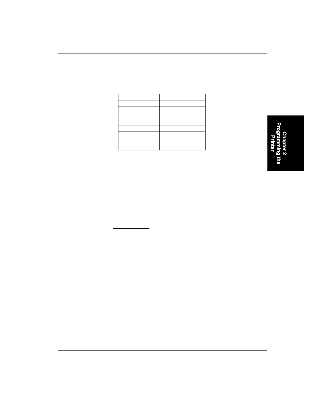
Bit Image Control - Creating 8-Pin Bit Images 2-41
Relation between Bit Numbers and
Print Head Pins
The table below shows the bit numbers and corresponding print head pin
numbers for one column of bit image.
Bit Number Print Head Pins
Bit 7 (MSB) Pin #1
Bit 6 Pin #2
Bit 5 Pin #3
Bit 4 Pin #4
Bit 3 Pin #5
Bit 2 Pin #6
Bit 1 Pin #7
Bit 0 (LSB) Pin #8
ESC K Set Single-density Bit Image Mode
Format
ESC K n1 n2 data
n1 and n2 : Total number of columns to print bit image =
n1 + n2 x 256
1 <= n1 + 256 x n2 <= 480
data: Bit image data
Dec. 27 75 n1 n2 data
Hex. 1B 4B n1 n2 data
Function
Prints 8-pin bit images at the single or standard horizontal density (60
dots/inch) for (n1 + n2 x 256) columns. Define n1 , n2 , and data in the
same way as for the ESC * command.
ESC L Set Double-Density Bit Image Mode
Format
ESC L n1 n2 data
n1 and n2 : Total number of columns to print bit image =
n1 + n2 x 256
1 <= n1 + 256 x n2 <= 960
data: Bit image data
Dec. 27 76 n1 n2 data
Hex. 1B 4C n1 n2 data
E-EQ-2325VPRG-A-ARC 2325 Vehicle Printer Reference Guide
Page 70

2-42 Bit Image Control - Creating 8-Pin Bit Images
Function
Prints 8-pin bit images at double horizontal density (120 dots/ inch) for
(n1 + n2 x 256) columns. Adjacent dots are printed so that the printing
speed is reduced. Define n1 , n2 , and data in the same way as for the
ESC * command.
ESC Y Set Double-Speed and Double-Density Bit Image Mode
Format
ESC Y n1 n2 data
n1 and n2 : Total number of columns to print bit image =
n1 + n2 x 256
1 <= n1 + 256 x n2 <= 960
data: Bit image data
Dec. 27 89 n1 n2 data
Hex. 1B 59 n1 n2 data
Function
Prints 8-pin bit images at double horizontal density (120 dots/inch) for
(n1 + n2 x 256) columns. Adjacent dots are not printed, so the printing
speed is not reduced as with an ESC L command. Define n1 , n2 , and
data in the same way as for the ESC * command.
ESC Z Set Quadruple-Density Bit Image Mode
Format
ESC Z n1 n2 data
n1 and n2 : Total number of columns to print bit image =
n1 + n2 x 256
1 <= n1 + 256 x n2 <= 1920
data: Bit image data
Dec. 27 90 n1 n2 data
Hex. 1B 5A n1 n2 data
Function
Prints 8-pin bit images at quadruple horizontal density (240 dots/inch)
for (n1 + n2 x 256) columns. Adjacent dots are not printed so that the
printing speed is not reduced. Define n1 , n2 , and data in the same way
as for the ESC * command.
2325 Vehicle Printer Reference Guide E-EQ-2325VPRG-A-ARC
Page 71

Bit Image Control - Density Change 2-43
Density Change
ESC ? Change Bit Image Density
Format
ESC ? n m
n: Specify the desired bit image command.
n = “K”, “L”, “Y”, or “Z”
m: Same density option as the ESC * m command
00H <= m <= 07H or 30H <= m <= 37H
Dec. 27 63 n m
Hex. 1B 3F n m
Function
Changes the bit image density set by an ESC K, ESC L, ESC Y, or ESC
Z command according to the same density option as that of the ESC *
command.
If you have defined a bit image mode and data with an ESC K, ESC L,
ESC Y, or ESC Z command, you can easily change the density with this
command.
n selects any of the ESC K, ESC L, ESC Y, or ESC Z commands. m
specifies the bit image density equivalent to the option for the ESC *
command. The density set by this command remains effective until
another density is specified.
See also ESC K, ESC L, ESC Y, ESC Z, and ESC * commands.
m
0 Single-density 60 480 ESC K
1 Double-
2 Double-speed
3 Quadruple-
E-EQ-2325VPRG-A-ARC 2325 Vehicle Printer Reference Guide
Bit Image
Mode
density
and Doubledensity
density
Horizontal
Density
(dots/inch)
120 960 ESC L
120 960 ESC Y
240 1920 ESC Z
Max.
Number of
Dots/Line
Equivalent
Codes
Page 72

2-44 Bit Image Control - Density Change
m
Bit Image
Mode
Horizontal
Density
(dots/inch)
4 CRT Graphic
I
5 Single-density
Plotter
Graphics
6 CRT Graphic
II
7 Double-
density Plotter
Graphics
ESC r Select International Character Set
Format
ESC r n
Dec. 27 114 n
Hex. 1B 72 n
Max.
Number of
Equivalent
Dots/Line
80 640 ---
72 576 ---
90 720 ---
144 1152 ---
Codes
Function
Selects the international character set according to n as listed below:
n = 00H USA
n = 01H France I
n = 02H Germany
n = 03H UK I
n = 04H Denmark I
n = 05H Sweden
n = 06H Italy
n = 07H Spain I
n = 08H Netherlands
n = 09H Norway I
n = 0AH Denmark II
2325 Vehicle Printer Reference Guide E-EQ-2325VPRG-A-ARC
Page 73

Bit Image Control - Density Change 2-45
n = 0BH Spain II
n = 0CH UK II
n = 0DH France II
n = 0EH Norway II
n = 0FH South Africa
n = 10H Japan
n = 11H Latin America
The USA character set is the default.
E-EQ-2325VPRG-A-ARC 2325 Vehicle Printer Reference Guide
Page 74

2-46 Bit Image Control - Density Change
2325 Vehicle Printer Reference Guide E-EQ-2325VPRG-A-ARC
Page 75

Table of Contents
CHAPTER 3 CHARACTER SET TABLES 3-1
Character Set 1................................................................................... 3-1
Character Set 2................................................................................... 3-2
All-Character Code Set ...................................................................... 3-3
Multilingual Character Set 1.............................................................. 3-4
Multilingual Character Set 2.............................................................. 3-5
Multilingual, All-Character Set .......................................................... 3-6
Other 17 Countries............................................................................. 3-7
E-EQ-2325VPRG-A-ARC 2325 Vehicle Printer Reference Guide
Page 76

3-ii Table of Contents
2325 Vehicle Printer Reference Guide E-EQ-2325VPRG-A-ARC
Page 77
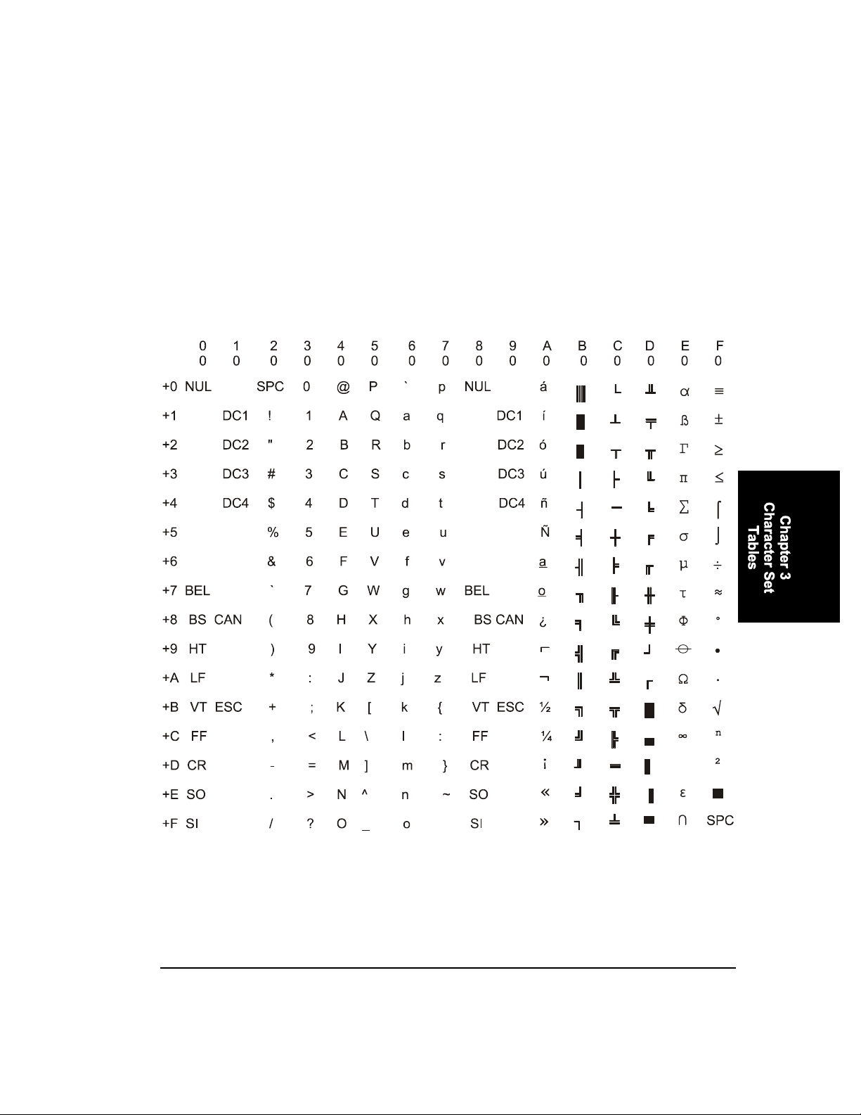
Character Set 1
Chapter 3
Character Set Tables
E-EQ-2325VPRG-A-ARC 2325 Vehicle Printer Reference Guide
Page 78
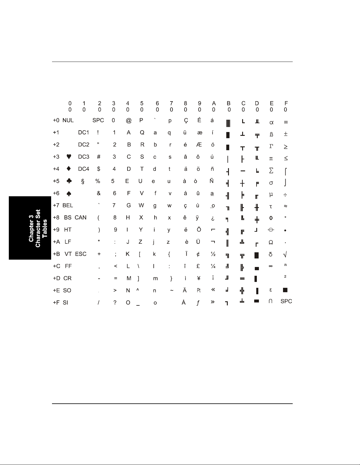
3-2 Character Set 2
Character Set 2
2325 Vehicle Printer Reference Guide E-EQ-2325VPRG-A-ARC
Page 79
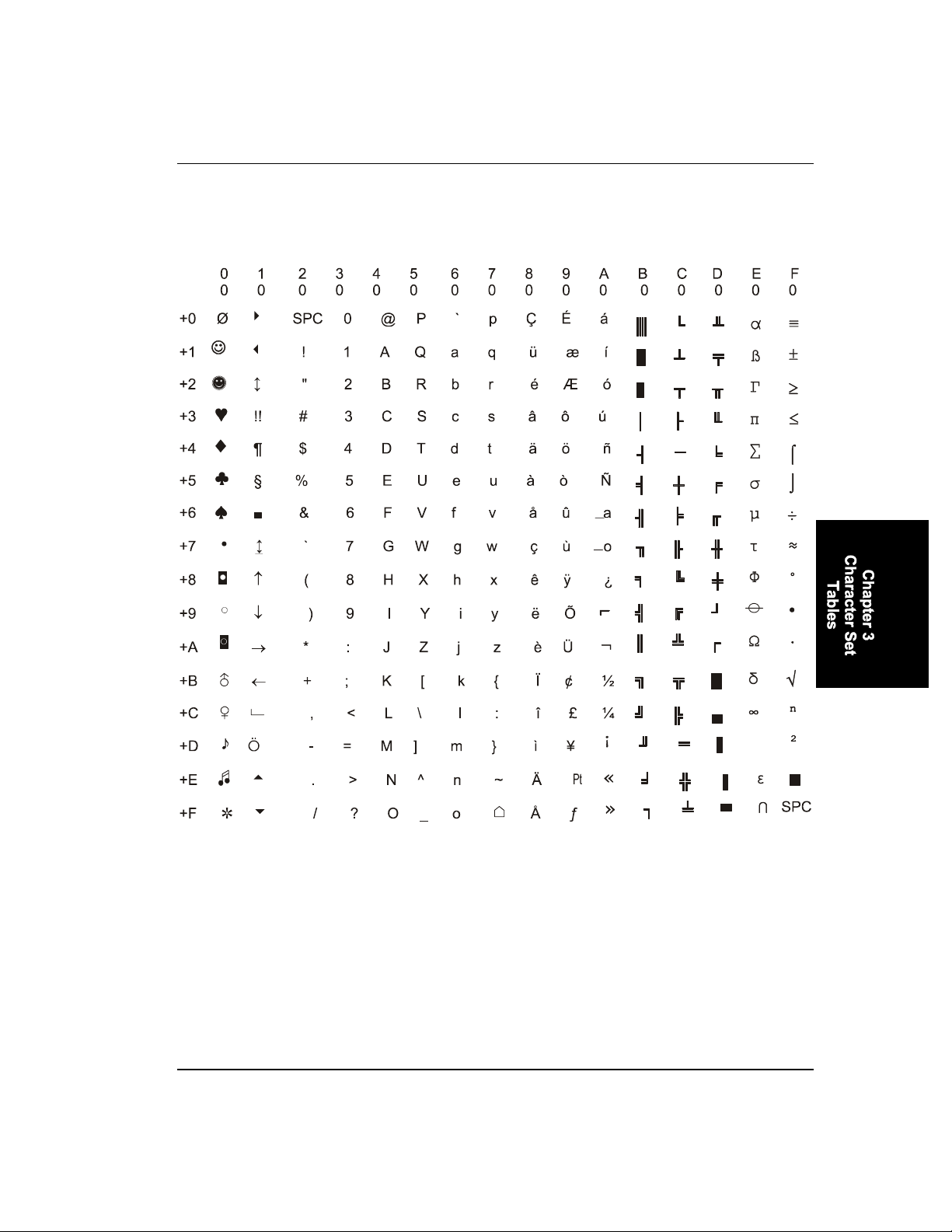
All-Character Code Set 3-3
All-Character Code Set
E-EQ-2325VPRG-A-ARC 2325 Vehicle Printer Reference Guide
Page 80
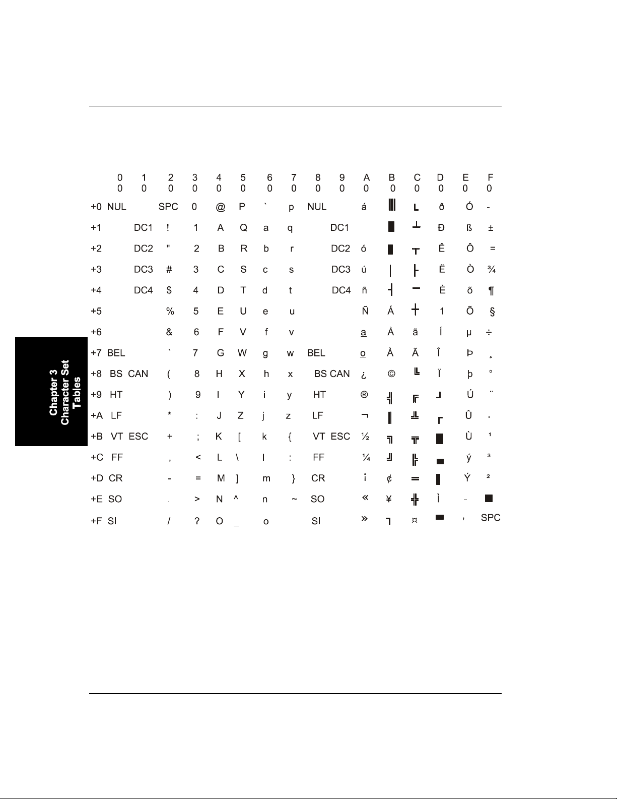
3-4 Multilingual Character Set 1
Multilingual Character Set 1
2325 Vehicle Printer Reference Guide E-EQ-2325VPRG-A-ARC
Page 81
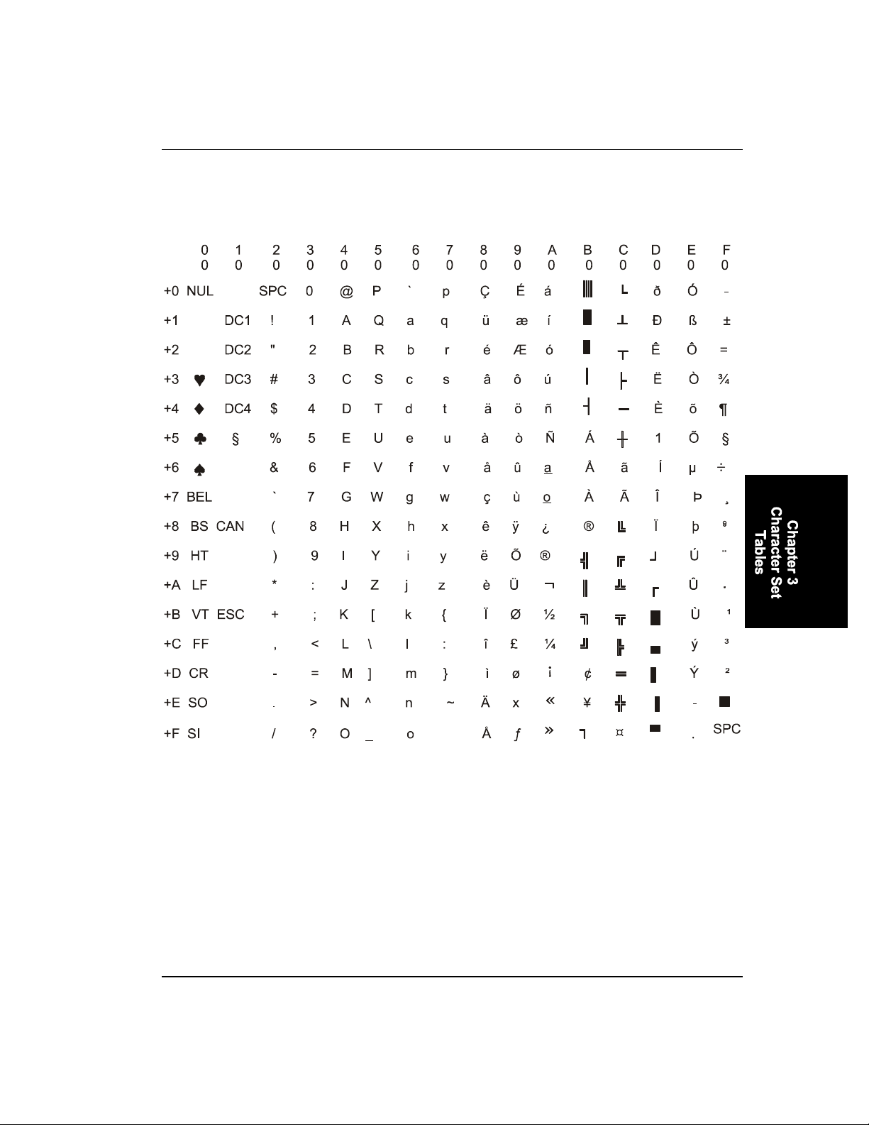
Multilingual Character Set 2 3-5
Multilingual Character Set 2
E-EQ-2325VPRG-A-ARC 2325 Vehicle Printer Reference Guide
Page 82
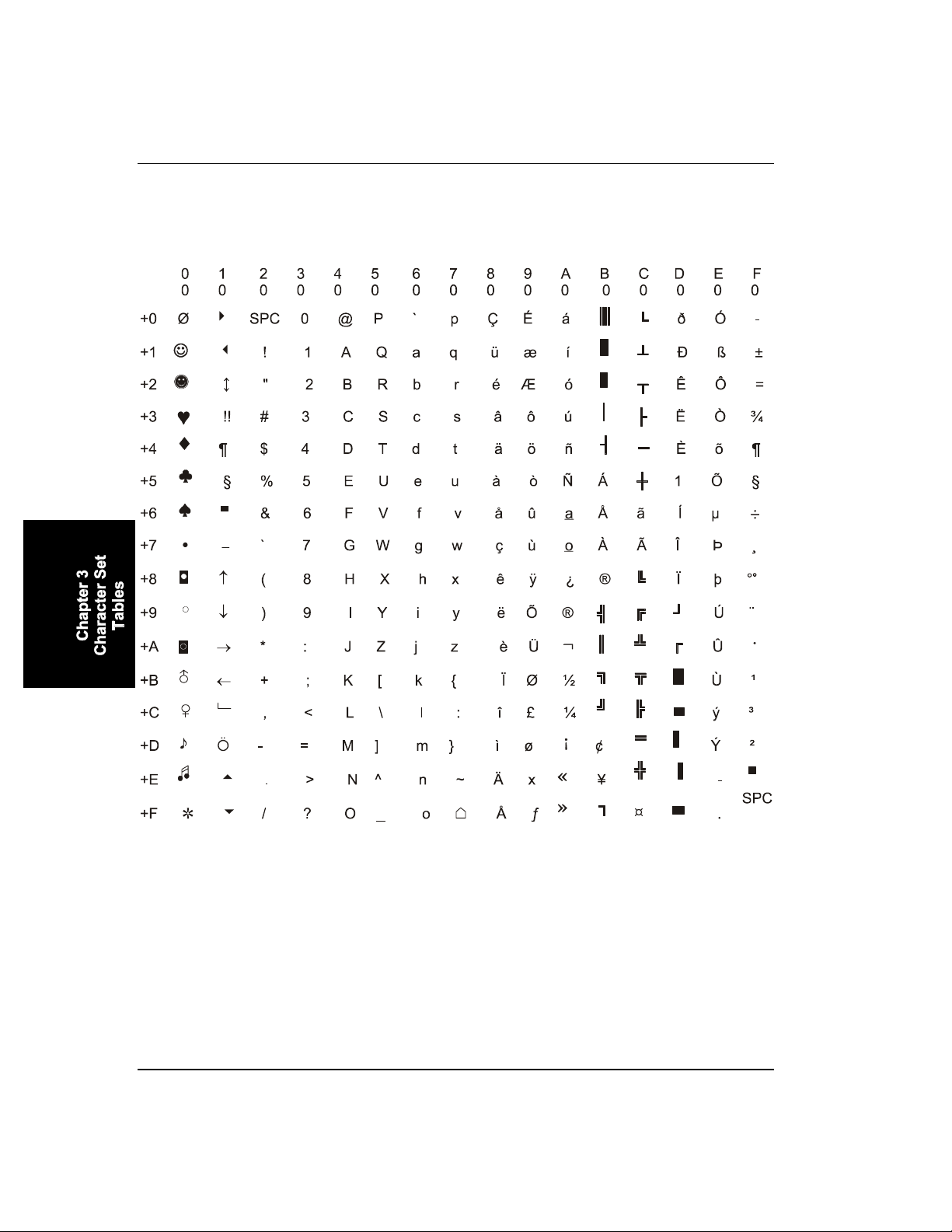
3-6 Multilingual, All-Character Set
Multilingual, All-Character Set
2325 Vehicle Printer Reference Guide E-EQ-2325VPRG-A-ARC
Page 83

Other 17 Countries 3-7
Other 17 Countries
E-EQ-2325VPRG-A-ARC 2325 Vehicle Printer Reference Guide
Page 84

3-8 Other 17 Countries
2325 Vehicle Printer Reference Guide E-EQ-2325VPRG-A-ARC
Page 85

Table of Contents
CHAPTER 4 SOFTWARE CONTROLLED UNIVERSAL
ERIAL SWITCH (SCUSS) 4-1
S
Introduction ........................................................................................ 4-1
Example........................................................................................................4-2
SETPRINT.C........................................................................................ 4-3
E-EQ-2325VPRG-A-ARC 2325 Vehicle Printer Reference Guide
Page 86

4-ii Table of Contents
2325 Vehicle Printer Reference Guide E-EQ-2325VPRG-A-ARC
Page 87

Introduction
Chapter 4
Software Controlled Universal
Serial Switch (SCUSS)
Note: Using the Software Controlled Universal Serial Switch is
optional, not required and only necessary when a modem
board is installed.
The theory behind this design is to have the 2325 provide the necessary
RTS signals so that the MCU can disconnect all drivers tied to the bus,
effectively leaving only itself connected to the handheld computer.
The MCU then sends an <ACK> back to the 2325 at 4800 baud, and
waits for a character to be received via its serial port at 4800 baud. The
character will be an ASCII 1, 2, 3, 4, 5, or 6. The number indicates
which port will be selected. The MCU then echoes the complement of
the byte received back to the 2325 at 4800 baud. The reason the
complement of the byte received was chosen was so that the 2325 would
not mistake the SCUSS MCU to be the modem. The MCU now enables
the port specified by the number received.
ASCII 1 = 31h = Printer specified (power-up default port)
ASCII 2 = 32h = Standard serial port specified
ASCII 3 = 33h = Modem specified.
The SCUSS firmware allows the 2325 approximately 500 mSec to
receive the ASCII character. If the character is not received in this
window of time or if a bad character is received the SCUSS will switch
back to the default port.
E-EQ-2325VPRG-A-ARC 2325 Vehicle Printer Reference Guide
Page 88

4-2 Introduction
Example
1. Close COM1 on 2325 if open.
2. Open COM1 at 4800, n, 8,1 – RTS on.
3. Toggle RTS on wait .05 mSec toggle RTS off , wait .05 mSec.
4. Repeat step #3 a total of 5 times.
5. Toggle RTS on wait 50mSec toggle RTS on wait 50 mSec.
6. Repeat step #5 a total of 4 times.
7. After waiting 180 mSec read COM1 (should be an <ACK>).
8. Send character out COM1 (ASCII 1, 2 or 3).
9. Read COM1 should be complement of ASCII character sent.
10. Close port COM1.
2325 Vehicle Printer Reference Guide E-EQ-2325VPRG-A-ARC
Page 89

SETPRINT.C 4-3
SETPRINT.C
/*
* Filename: setprint.c
*
* NOTES: This function switches the printer SCUSS board.
* The greenleaf comm library is used for this example.
*
*/
#include <stdio.h>
#include <stdlib.h>
#include "gsci.h"
#define PRINTER 0x31
#define SERIAL 0x32
#define MODEM 0x33
int SetPrinter( int device )
{
int status;
short c=0x30, i=0,j;
status = asiopen( COM1, ASINOUT | BINARY | NORMALRX, 100, 100,
4800L, P_NONE, 1, 8, ON, ON );
if ( status < ASSUCCESS )
{
printf( "Failed to open the port. Status = %s\n",
CommErrorName( status ) );
return( 1 );
}
for( i = 0; i < 5; i++ )
{
asrts( COM1, OFF );
for( j = 0; j < 55; j++ ) /* provides a 50 uSec delay */
;
asrts( COM1, ON );
for( j = 0; j < 55; j++ ) /* provides a 50 uSec delay */
;
}
for( i = 0; i < 4; i++ )
{
timer(1); /* provides a 50 mSec delay */
asrts( COM1, OFF );
timer(1); /* provides a 50 mSec delay */
asrts( COM1, ON );
}
timer( TICKS_PER_SECOND / 8 );
c = 0xff;
c = asigetc( COM1 );
if ( c == 0x06 )
{
asiputc( COM1, (char)device );
printf( "ACK received\n%d sent\n", device );
E-EQ-2325VPRG-A-ARC 2325 Vehicle Printer Reference Guide
Page 90

4-4 SETPRINT.C
}
else
putc( c, stdout );
timer( TICKS_PER_SECOND / 10 );
c = asigetc( COM1 );
c = ~c;
c = c&0x00ff;
if( c == device )
printf("Switch OK\n");
else
printf("Switch failed\n");
asrts( COM1, OFF );
asiquit( COM1 );
return 0;
}
2325 Vehicle Printer Reference Guide E-EQ-2325VPRG-A-ARC
Page 91

Index -A- 1
Index
5 VDC at 200mA.................................... 1-7
A
Activate Line Spacing........................... 2-19
Activate Skip-Over Perforation ............ 2-18
Advance Paper...................................... 2-17
All Character Code Set ......................... 2-29
All Character Code Set, One................. 2-29
Auto CR.................................................. 2-1
Auto line feed ......................................... 2-1
Character Set.........................................2-28
Character set table...................................2-1
Character Set Tables ...............................3-1
Clear Printer Buffer...............................2-10
Code Set, All Character.........................2-29
Condensed Characters...........................2-30
Continuous Feed....................................1-11
Control Commands
Printer ....................................................2-2
D
B
Backspace............................................. 2-11
Battery
Connect to Vehicle ................................ 1-5
Insert in Printer...................................... 1-3
Internal, Installation............................... 1-3
Life ........................................................ 1-4
Battery, 2325
Charge in Cradle.................................... 1-9
Baud Rates
Settings ................................................ 1-16
Bit Image Mode.................................... 2-39
Bit image printing*2 ............................... 2-1
Bit Image, Density Change ................... 2-45
Bit Image, Double Density ................... 2-43
Bit Image, Double Density and Double
Speed ................................................ 2-43
Bit Image, International Character Set.. 2-47
Bit Image, Quadruple Density .............. 2-44
Bit Image, Single Density..................... 2-42
Bit Images............................................. 2-39
Bit Numbers and Print Head Pins
Table.................................................... 2-42
Buttons.................................................... 1-9
Deactivate Skip-Over Perforation .........2-18
Default Settings.....................................1-15
Deselect Printer.....................................2-10
Dimensions............................................1-10
Dip Switch
Function Table .....................................1-15
Disable Paper Empty Sensor................. 2-15
Double High, Double Wide...................2-35
Double Strike Character........................ 2-33
Double Strike Character, Cancel........... 2-33
Double Wide Cancel ............................. 2-30
Double-wide Line..................................2-30
E
Elite Pitch.............................................. 2-27
Emphasized Mode.................................2-32
Emphasized Mode, Cancel....................2-32
Enable Paper Empty Sensor..................2-15
F
Factory Settings.....................................1-15
Form Feed .............................................2-16
Fuse
Replacement...........................................1-6
C
H
Cancel/Set Double Wide Character ...... 2-34
Carriage Return..................................... 2-11
E-EQ-2325VPRG-A-ARC 2325 Vehicle Printer Reference Guide
Horizontal Tab ......................................2-24
Page 92

2 -I- Index
Horizontal Tab Stops............................ 2-25
HT setting ............................................... 2-1
I
Indicators ....................................... 1-9, 1-13
Initialize Printer ...................................... 2-6
Install
Fuse ....................................................... 1-6
Installation
Printer .................................................... 1-3
International character set.............. 2-1, 2-47
IrDA Circuitry and Baud Rate .............. 1-16
IrDA Driver, 2325 .................................. 1-1
K
Keypad.................................................. 1-11
L
Left margin ............................................. 2-1
Line Feed.............................................. 2-16
Line feed pitch........................................ 2-1
Line Feed Reverse ................................ 2-17
Line Spacing......................................... 2-19
Low Temperature Operation, Mode
Command...............................................2-9
Lights, Condition Explained ................1-13
Paper Tray Capacity................................1-9
Paper, Type of.........................................1-9
Phillips screwdriver.................................1-4
Pica Pitch ..............................................2-27
Pin 9
Supplys 5 VDC ......................................1-7
Power Input Requirement...................... 1-10
Print attributes *1....................................2-1
Print Mode and Speed.............................1-9
Print Mode Selection.............................2-38
Print Mode, Change ..............................2-31
Print quality and pitch.............................2-1
Printer
Connect to Vehicle.................................1-5
Printer Configuration
How To ................................................1-15
Printer Default Settings...........................2-1
Printer Panel..........................................1-11
Proportional Spacing.............................2-28
R
Restore Default Tab Settings.................2-25
Ribbon, Brother.......................................1-9
Right margin............................................ 2-1
RS-232 Pinouts .......................................1-7
M
Margins, Left and Right........................ 2-22
Modem, SCUSS interaction.................... 4-1
N
NLQ font................................................. 2-1
NLQ Font Select................................... 2-26
NLQ or graphic character printing*2...... 2-1
Normal printing ...................................... 2-1
O
Overline Function................................. 2-37
P
Page length ....................................2-1, 2-21
Panel
2325 Vehicle Printer Reference Guide E-EQ-2325VPRG-A-ARC
S
Select Print Quality ...............................2-13
Select Printer.........................................2-10
Self Test ................................................1-12
Set 2/16 Spacing....................................2-20
Set 7/72" Line Spacing..........................2-19
Set 72" Spacing.....................................2-20
Set Bi-directional or unidirectional
printing..............................................2-14
Set Unidirectional Printing....................2-14
Set/Cancel Auto Line Feed....................2-12
Skip-over perforation .................... 2-1, 2-18
Software Controlled Universal Serial Switch
............................................................4-1
Specifications..........................................1-9
Subscript ...............................................2-33
Superscript ............................................2-33
Page 93

Index -T- 3
T
Tab Settings, Restore Default............... 2-25
Tab, Horizontal..................................... 2-24
Tab, Vertical ......................................... 2-24
Temperature Ranges
Recommended ..................................... 1-10
Top of Form.................................1-11, 2-22
U
Underline .............................................. 2-32
V
Vertical Tab ..........................................2-24
Vibration and shock ................................1-3
VT setting................................................2-1
W
Weight...................................................1-10
Wire to Vehicle Ground..........................1-5
E-EQ-2325VPRG-A-ARC 2325 Vehicle Printer Reference Guide
Page 94

4 -W- Index
2325 Vehicle Printer Reference Guide E-EQ-2325VPRG-A-ARC
 Loading...