

Page 1
Mi5 Polarizer
Model pictured:
Mi5 Polarizer
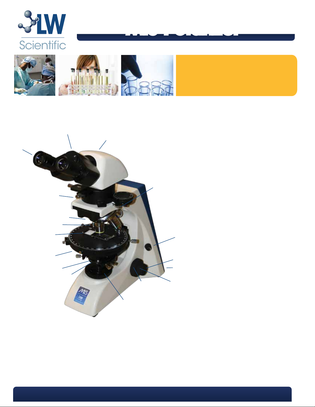
A
B
R
D
Q
P
O
N
M
L
K
I
E
F
G
H
A Diopter Adjustment
B Head
C Light Port Slide
(trinoc only)
D Head Retention Screw
E Brightness Control
F Fine Focus
G On/Off Switch
(located on rear)
H Coarse Focus
I Focus Friction Control
(left side only)
J Base Condenser
K Substage Abbe Condenser
L Substage Iris Diaphragm
M Stage
N Slide Holder
O Objectives
P Nosepiece
Q Analyzer Module
R Eyepieces
J
P. 770.270.1394 F. 770.270.2389 865 Marathon Parkway Lawrenceville GA 30046
Page 2
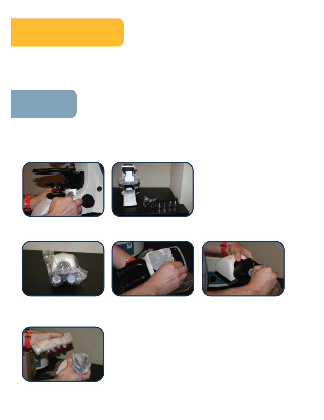
LW Scientific packs each Mi5 Microscope with utmost care. Examine the outer
and inner containers for any visual damage. Retain all of the packing material
Unpacking and Setup
distributor where you purchased the microscope. Please retain all packaging material for future use. Carefully unpack
your Mi5 Microscope using the following checklist for all the parts and accessories:
Box 1: Head of microscope
Box 2: All accessories for scopes
Box 3: Base of microscope & objectives
until you have examined and tested your new microscope. If there is
damage, please contact the shipping company, as our warranty does not
cover shipping damage. If you are uncertain who the shipper is, contact the
Unpacking
Remove all 3 small boxes from the large box and set on a firm work area.
Open Box # 3 and take out microscope base. Set on table/bench. Carefully remove all Styrofoam, zip ties from
1
stage (if applicable), and tissue paper and finally, any applicable stickers from stage. Next, pull out the (4) objectives
and the (2) eyepieces from the top Styrofoam container--set them on the table (these will be used in the microscope
assembly steps).
Open Box # 1 labeled: Binoc/Trinoc Head. Open the box and carefully open plastic bag with the microscope head
2
in it and set it aside. Next, remove the eyepiece caps and tissue from the bottom of the binoc/trinoc head.
Open Box #2 labeled: Analyzer Module and Accessories. Carefully remove items from foam/bubble wrap packaging
3
and set the analyzer module next to the microscope base and binoc/trinoc head. You should now have the basic 3
components to assemble your microscope.
Page 3

Maintenance
Always cover your microscope with the dust cover when not in use. When cleaning the lenses, use lens paper or a
1
cotton swab dipped in lens cleaning solution.
Excess oil should be cleaned off your 100x objective and stage at once. An alcohol pad is best for removing oil from
2
the stage and on the other metal parts, but is not recommended for use on the lenses. Use lens cleaning solution and
lens paper to clean off your objectives.
Dust in the nosepiece or ocular tubes should be blown out using filtered air. Canned air dusters work well for this job.
3
Whenever you remove an objective, we recommend that you place it back into the original plastic shipping vial until
4
ready to be placed back on the microscope. SCREW THE OBJECTIVE SECURELY INTO THE CAP OF THE HOLDER - DO NOT
DROP OBJECTIVE LOOSELY INTO CONTAINER.
To keep your microscope in top condition for years, LW Scientific recommends that you have the microscope
5
professionally serviced once a year.
Warning: The 40x and 60x objective is not sealed for oil immersion. Damage to the 40x and 60x objective due to oil
immersion is not covered under warranty.
Uric Slides
Uric acid is created when the body breaks down purine nucleotides. High concentrations of uric acid in blood serum
can lead to a type of arthritis known as gout. In gout patients, crystals typically deposit in joint fluids (synovial fluid),
which cause pain and swelling of the affected joint. The crystals are reviewed and identified using polarized
microscopy. The forms may vary from rectangular to needle shape crystals.
The crystals seen in the enclosed preparation are prepared from uric acid. The slide contains mostly the rectangular
forms with some needle shapes. This slide makes an ideal control for utilizing polarizing microscopy.
There is no expiration date on these slides.
Page 4

Assembly
First, remove the cap from the top of the microscope base and put back in the box.
1
Unscrew the set screw to enable the Analyzer Module to be inserted on to the top of the microscope base. Take the
2
Analyzer Module” and ensure that the silver pin in positioned on the bottom and towards the back. It should align with the
notch on the microscope base. Screw down the set screw to ensure the Analyzer Module is securely in place.
Next, take the included Allen wrench and slightly loosen the hex head screw on the top of the Analyzer Module’ (*be sure
3
NOT to loosen all the way) and remove plastic cap.
Take the binoc/trinoc head and carefully insert it onto the top of the Analyzer Module. Ensure that the flange on the head
4
of the microscope is firmly flush with the base. To secure the head of the microscope to the Analyzer Module, screw back in
the Allen screw and securely fasten. *BE SURE NOT TO OVERTIGHTEN*
Page 5

Assembly Cont.
Next, take each objective and secure into place, making sure that the objectives go from lowest power to highest
5
power while you turn the nosepiece in a clockwise rotation.
To install the light condenser, move the nosepiece to the 4x objective position, raise the stage up as high as it will go, and
6
then, lower the condenser tray underneath the stage. Simply insert the condenser into the grooves in the tray being sure
to align the notch at the back of the tray to the centered nodule located at the back of the light condenser.
Now that your microscope is partially assembled, it is time to assemble the polarizing portion. Carefully remove the
7
analyzer. Remove the end screw and place it on the counter. Insert the analyzer from the right-hand side of the scope.
Gently push the analyzer through the ‘analyzer module’ until you hear 2 clicks. The polarizing analyzer is now in place.
Lastly, screw the end set screw back into place as to ensure the analyzer cannot be pulled out.
8
Next, take the wave plate ( aslo known as a red compensator) [labeled in white on black slide] and insert into open slot.
*Be sure that the white writing is facing up. Gently push the filter into the slot until you hear/feel a click-stop. Now the
filter is in place.
9
This next step is important, pull the Bertrand Lens out. This will allow a clear image while viewing trough the microscope
head. Lastly, please be sure to loosen the stage locking screw and the polarizing locking screw.
Page 6

Specifications
Nosepiece
Reverse quintuple nosepiece
Multiple ball bearing mounted
Head
Diopter adjustment +/-5
Inclined 30°
10X/20X Super WF HP eyepieces;
numbered cross scale
Focusable eyepiece with numbered cross
scale reticle
Interpupillary distance range 50-75mm
Illumination
Moveable Abbe condenser, NA 1.25
Iris Diaphram
6V/20W Clear Halogen illumination
Variable light adjustment: 0-20W output
90-240V / 50-60Hz automatic-switching
power cord
Stage
Center-adjustable stage (153mm diameter)
360 degree rotation; 1 degree increments
Center adjustable
Tension control knob
Slide clips (mechanical add-on available)
Focus
Coarse adjustment: range of 22mm
Fine adjustment: graduation of 2μm
Tension control knoble)
Objectives
Infinity Plan objectives
4x, 10x, 20x, 40x
60x dry available
Anti-fungal, parfocal, parcentric, color-coded
Analyzer & Accessories
Uric Acid Control slide
Polarizing analyzer with 360 degree increments
Red Compensator lens (λ); (λ/4) lens;
Quartz Wedge Bertrand lens
Dimensions and Weight
Height: 15.6” (396 mm)
Length: 16.5” (420 mm)
Width: 8.1” (206 mm)
Weight: Trinoc: 20.5 lbs.
Binoc: 20.0 lbs.
Objectives: The following numbers are
based on use with 10x/20 eyepieces.
Size
4X 0.10 40X 5.0mm
10X 0.25 100X 2.0mm
20X 0.40 200X 1.0mm
40XR 0.65 400X 0.5mm
50XR 0.95 0.4mm500X
60XR 0.85 0.33mm600X
100XR 1.25 0.2mm1000X
N.A. Mag. Field of View
Working Distance
6.73mm
4.19mm
2.14mm
.45mm
.29mm
.21mm
.12mm
P. 770.270.1394 F. 770.270.2389 865 Marathon Parkway Lawrenceville GA 30046
 Loading...