


TX9100E
SMART TEMP® UNIVERSAL PROGRAMMABLE THERMOSTAT
FOR BOTH CONVENTIONAL AND HEAT PUMP SYSTEMS |
52032 |
INSTALLATION AND OPERATING INSTRUCTIONS
IMPORTANT!
•Please read all instructions carefully before beginning installation
•Label the terminal designations on your existing wiring before removing your existing thermostat
•Ignore the color of the wires since they may not comply with any standard.
Thank you for your confidence in our product. To obtain the best results from your investment, please read these instructions and acquaint yourself with your purchase. Follow the installation procedures carefully, and one step at a time. This will save you time and minimize the chance of damaging either the thermostat or the systems that it controls. These instructions may contain information beyond that required for your particular installation.
1. SYSTEM COMPATIBILITY . . . . . . . . 2 2. FEATURES . . . . . . . . . . . . . . . . . . 3 3. TOOLS REQUIRED . . . . . . . . . . . . . 3 4. SELECTING A LOCATION. . . . . . . . . 4 5. REMOVE OLD THERMOSTAT . . . . . . 5 6. MOUNT NEW THERMOSTAT . . . . . . 5 7. WIRING DIAGRAMS . . . . . . . . . . . . 6 8. HARDWARE SETUP OPTIONS . . . . 16
9. COMPLETE THE INSTALL . . . . . . . 18 10. FRONT PANEL ITEMS . . . . . . . . . . 19 11. OPERATING INSTRUCTIONS . . . . . 20 12. ADVANCED FEATURES . . . . . . . . . 24 13. PROGRAMMING . . . . . . . . . . . . . 29 14. BATTERIES AND MAINTENANCE. . . 30 15. TECHNICAL ASSISTANCE . . . . . . . 31 16. WARRANTY. . . . . . . . . . . . . . . . . 31
WARNING: Use Energizer® or DURACELL® Alkaline Batteries Only.
Energizer® is a registered trademark of Eveready Battery Company, Inc. DURACELL® is a registered trademark of The Gillette Company, Inc.
© 2008 LUX PRODUCTS CORPORATION. ALL RIGHTS RESERVED

TX9100E |
|
Up / Down Buttons |
LCD |
|
|
Display |
|
|
Screen |
|
Fan |
TU |
|
|
DAY |
|
|
: 72 |
|
Mode |
5 36PM HEAT |
F |
|
|
Switch |
COOL |
RESET |
|
|
PROGRAM |
|
FAN |
TEMERATURE |
HEAT |
NEXT |
||
PROGRAM |
|
|
|
R U N |
|
AUTO |
HEAT |
HOLD |
ON |
OFF |
|
SET |
|
COOL |
|
|
|
|
|
DAY/TIME |
COPY / EMER |
|
|
AIR FILTER |
|
|
LUX |
System
Mode
Switch
LUX Rotary Speed Dial® |
Quick Reference |
|
Instructions |
1. SYSTEM COMPATIBILITY
The electrical rating for this thermostat is 1.5A per terminal, with a maximum of 2.0A for all terminals combined.
COMPATIBLE WITH:
•Most 24-volt heating and cooling systems
•1 or 2 stage Heat / 1 stage Cool: Gas, Oil or Electric systems
•1 or 2 stage Heat / 1 stage Cool: Heat Pump systems
•3-wire hydronic (hot water) zone valves
•Gas Millivolt heaters
NOT COMPATIBLE WITH:
• 120/240 VAC line voltage systems without a transformer, ask your LUX dealer for thermostats to control these systems.
2

2. THERMOSTAT FEATURES
•Universal Compatibility (Conventional or Heat Pump)
•7 Day Programming
•4 Periods per Day
•Quick Copy Programming
•Exclusive LUX Speed Dial®
•Luxlight® EL (Electro-Luminescent) Illuminated Display
•Filter Monitor
•Programmable Keypad Lock
•Optional Smart Recovery
•Temperature Hold
•Temporary Temperature Override
•Energy Star Compliant
•Battery Free Memory Storage
•F/C Temperature Display
•12/24 Hr Clock Display
•Adjustable Temperature Differential / Cycle Rate
•User Temperature Calibration
•System or Battery Powered
•5/2 Minute Selectable Minimum Run/Off Time for Equipment Protection
Please read all of these instructions carefully before beginning installation, and save this manual for future reference.
3. TOOLS REQUIRED
•#1 Phillips screwdriver
•Drill with 3/16 in. (4.8mm) bit
•Wire Stripper / Cutter
3

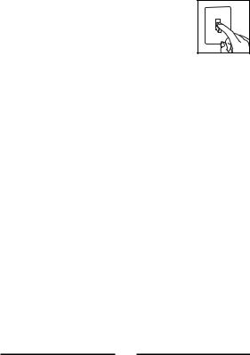
CAUTION:
This thermostat is protected against normal static electric discharges; however touching a grounded metal object before touching your thermostat will minimize the risk of damaging the unit in extremely dry weather.
4. SELECTING A LOCATION
On replacement installations, mount the new thermostat in place of the old one unless the conditions listed below suggest otherwise. On new installations, follow the guidelines listed below.
1.Locate the thermostat on an inside wall, about 5 ft. (1.5m) above the floor, and in a room that is used often.
2.Do not locate where air circulation is poor, such as in a corner or an alcove, or behind an open door.
3.Do not install it where there are unusual heating conditions, such as: in direct sunlight; near a lamp, television, radiator, register, or fireplace; near hot water pipes in a wall; near a stove on the other side of a wall.
4.Do not locate in unusual cooling conditions, such as: on a wall separating an unheated room; or in a draft from a stairwell, door, or window.
5.Do not locate in a damp area. This can lead to corrosion that may shorten thermostat life.
6.If painting or construction work has yet to be completed, cover the unit completely or do not install it.
WARNING:
•Read instructions carefully before removing any wires from your existing thermostat.
•All wiring must conform to the local codes and ordinances that are in your particular location.
4
•Your thermostat is a precision electronic instrument; please handle it with care to avoid damage.
5. REMOVE OLD THERMOSTAT
1. Turn OFF the electricity to all heating and cooling components. Do not turn the electricity back on until all work is completed.
2.Remove the cover and front portion of your old thermostat to expose the wiring connections.
3.Write down the letters printed near each wire terminal that is used, and the color of the wire that is connected to it. Using the enclosed labels, attach a label to each of your wires so that the letter matches the marking on your existing thermostat.
4.When they are all labeled, carefully remove the wires one at a time, making sure that they do not fall back inside the wall. Do not allow any of the bare wire ends to touch each other, or any parts on the thermostat.
5.Loosen all of the screws on the old thermostat and remove it from the wall.
6. MOUNT THE NEW THERMOSTAT
1.Strip insulation leaving 3/8 in. (9.5mm) bare wire ends and clean off any corrosion.
2.Fill wall opening with non-combustible insulation to prevent drafts from affecting the thermostat.
CAUTION:
Be careful not to drop the unit or disturb electronic parts. Leave the door closed while the body is being removed from the base.
5
3.Remove the body from the thermostat’s base by pressing the thumb latch at the bottom center of the unit and swinging the body away from the base.
NOTE:
If you are mounting the base to soft material like plasterboard or if you are using the old mounting holes, the screws may not hold. Drill a 3/16 in. (4.8mm) hole at each screw, and insert the plastic anchors provided.
4.Hold the base against the wall. Route the wires through the hole below the terminal block. Position the base for best appearance (to hide any marks from an old thermostat). Attach the base to the wall with the two screws provided.
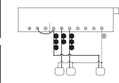
7. WIRING INFORMATION AND DIAGRAMS
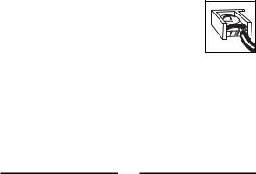
CONNECTING THE WIRES
5. Wires must be trapped between the black clamps and the brass terminals as shown here.
6. Securely tighten all of the electrical terminal screws, including any unused ones.
WIRING DIAGRAM NOTES:
(Important, please read all notes before connecting wires)
•If the information provided does not clearly represent your system configuration, please refer to the “TECHNICAL ASSISTANCE” section of this manual, and contact our support department before removing any of your existing thermostat wiring.
6

•All of the dashed wires shown in the following wiring diagrams are either optional, or their usage depends upon your specific system type or brand. For example: Diagram #1 shows the fan wire as optional. If your system does not have a fan, than this terminal will not be used.
•The optional “C” terminal is used for powering the thermostat by the 24 Volt system power. This can be used alone, or in addition to installing batteries.
•If “Y” and “C” wires are both present, then “C” is most likely a system common wire.
•For Heat Pump systems, use either the “O” terminal or the “B” terminal, but not both. If an “O” and a “B” wire are both present, “B” is likely a system common and may be connected to the “C” terminal. Connecting system common power to this thermostat’s “B” terminal may damage the thermostat, and also your system.
•If replacing a Honeywell TM-11, tape off the “R” wire. Connect the “B” wire to the “RH” terminal.
•If replacing an old thermostat that has a mechanical clock, there may be two wires labeled as “C” for the clock power. Tape off these wires and do not connect them to the “C” terminal of this thermostat.
7
8
|
|
|
|
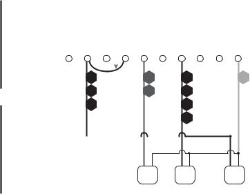
TYPICAL 24-VOLT, 2 OR 3 WIRE, CONVENTIONAL, |
|
|
|
#1 |
||||||||||||||||||||||||||||||
1-STAGE, HEATING ONLY SYSTEMS (INCLUDING MILLIVOLT) |
|
|||||||||||||||||||||||||||||||||||||
|
||||||||||||||||||||||||||||||||||||||
Factory RH-RC Jumper Wire Installed |
|
|
|
|
|
|
|
|
|
|
|
|
|
|
|
|
|
|
|
|
|
|
|
|||||||||||||||
A |
RH W2 |
|
RC |
G |
Y |
W1 O |
B |
C |
|
|||||||||||||||||||||||||||||
|
|
|||||||||||||||||||||||||||||||||||||
|
|
|
|
|
|
|
|
|
|
|
|
|
|
|
|
|
|
|
|
|
|
|
|
|
|
|
|
|
|
|
|
|
|
|
|
|
|
|
|
|
|
|
|
|
|
|
|
|
|
|
|
|
|
|
|
|
|
|
|
|
|
|
|
|
|
|
|
|
|
|
|
|
|
|
|
|
|
|
|
|
|
|
|
RH |
|
|
|
|
G |
|
|
|
W1 |
|
|
|
|
|
C |
|||||||||||||||||
|
|
|
|
|
|
|
R |
|
|
|
|
F |
|
|
|
|
W |
|
|
|
|
|
O |
|||||||||||||||
|
|
|
|
|
|
|
|
|
|
|
|
|
|
|
|
|
|
|
|
|
|
|
|
|
|
|
|
|
|
|
|
|
|
|
|
|
P |
|
|
|
|
|
|
|
|
V |
|
|
|
|
|
|
|
|
|
|
|
|
H |
|
|
|
|
|
T |
||||||||||||
|
|
|
|
|
|
|
|
|
|
|
|
|
|
|
|
|
|
|
|
|
|
|
|
|
|
|
|
|
|
|
|
|
|
|
|
|
I |
|
|
|
|
|
|
|
|
|
|
|
|
|
|
|
|
|
|
|
|
|
|
|
|
|
4 |
|
|
|
|
|
|
|
|
O |
|||||
|
|
|
|
|
|
|
|
|
|
|
|
|
|
|
|
|
|
|
|
|
|
|
|
|
|
|
|
|
|
|
|
N |
||||||
|
|
|
|
|
|
|
|
|
|
|
|
|
|
|
|
|
|
|
|
|
|
|
|
|
|
|
|
|
|
|
|
|
|
|
|
|
A |
|
|
|
|
|
|
|
|
|
|
|
|
|
|
|
|
|
|
|
|
|
|
|
|
|
|
|
|
|
|
|
|
|
|
|
|
|
|
L |
|
FAN |
HEATER |
SYSTEM |
|
XFMR |
|||
|
|
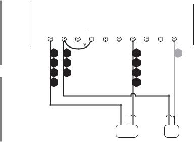
TYPICAL 24-VOLT, CONVENTIONAL, 1-STAGE, HOT WATER |
#2 |
||
HEAT ONLY SYSTEMS WITH A 3-WIRE ZONE VALVE |
|
||
|
|||
|
|
|
|
|
Factory RH-RC Jumper Wire Installed |
|
|
|
|
|
|
|||
|
A |
RH |
W2 |
RC |
G |
Y |
W1 |
O |
B |
C |
|
A |
RH |
|
|
|
|
W1 |
|
|
C |
|
6 |
R |
|
|
|
|
W |
|
|
O |
9 |
|
|
|
|
|
|
|
|
|
P |
Y |
V |
|
|
|
|
H |
|
|
T |
|
|
|
|
|
|
|
|
||||
|
|
|
|
|
|
|
|
|
|
I |
|
3 |
|
|
|
|
|
4 |
|
|
O |
|
|
|
|
|
|
|
|
N |
||
|
|
|
|
|
|
|
|
|
|
|
|
|
|
|
|
|
|
|
|
|
A |
|
|
|
|
|
|
|
|
|
|
L |
3-WIRE |
SYSTEM |
|
HYDRONIC |
||
XFMR |
||
ZONE VALVE |
||
|
10
|
TYPICAL 24-VOLT, 3 WIRE, CONVENTIONAL, |
#3 |
|||
|
1-STAGE COOLING ONLY SYSTEMS |
|
|
||
Factory RH-RC Jumper Wire Installed |
|
|
|
||
A |
RH W2 RC |
G |
Y W1 O |
B |
C |
|
RC |
G |
Y |
|
C |
|
R |
F |
C* |
|
O |
|
|
|
|
|
P |
|
5 |
|
6 |
|
T |
|
|
|
|
|
I |
|
|
|
|
|
O |
|
|
|
|
|
N |
|
|
|
|
|
A |
|
|
|
|
|
L |
|
|
FAN |
A/C |
|
SYSTEM |
|
|
UNIT |
|
XFMR |
|
|
|
|
|
||
 Loading...