

Page 1
Instruction Sheet - Endura Mobile Cabinet Tables
Models LE27C
Customer Service Department
Luxor
2245 Delany Road
Waukegan, IL 60087
Ph: 847/244-1800 • 800/323-4656
Fax: 847/244-1818 • 800/327-1698
LE27C
PARTS LIST
Models LE27C
1 - Top shelf w/handle 1 - Grommet Cap
1 - Bottom shelf w/caster sockets 1 - Cord guide cover
4
- Legs 2 - Grommet rings
2 - Cabinet side panels 1 - Rubber Band
1 - Back Panel 4 - Small ‘U” brackets
1 - Door in frame 1 - Large “U” bracket
1 - Power cord 1 - Cord wrap bracket
4 - Casters 2 with brake 2 - Stove bolts
8 - 1 3/4” machine screws
Tools Required:
Rubber mallet
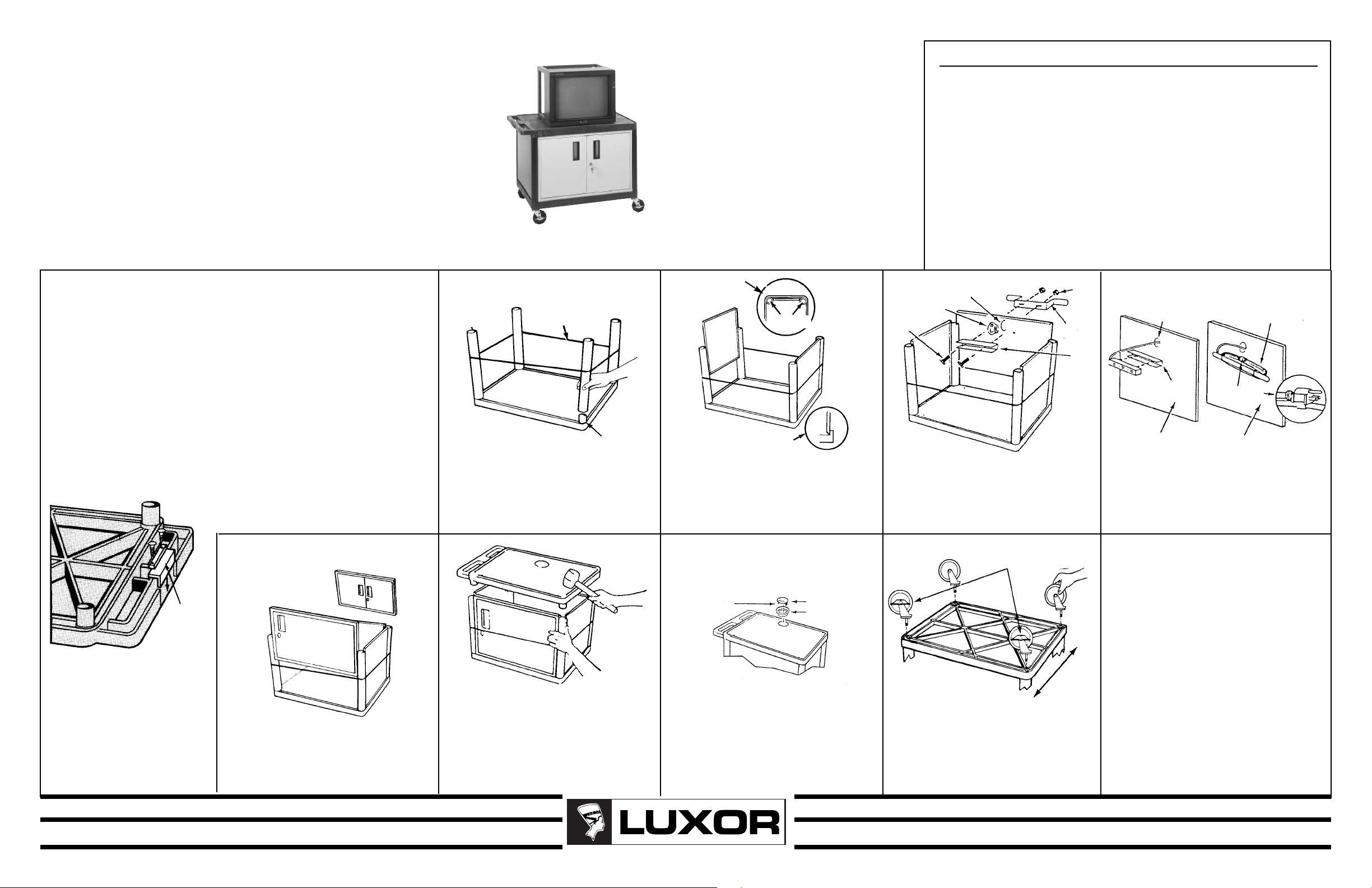
If you did not get an
electric assembly with
your cart start by closing
the electric plug housing
in the handle of the top
shelf as illustr
ated below.
PLUG
HOUSING
COVER
NOTE: Model LE-27C had double doors.
RUBBER BAND
BOTTOM
SHELF
LEG POST
1
With bottom shelf facing up push all four legs
onto leg posts. Using rubber mallet hammer legs
firmly into position. Legs must be seated (flush)
against the shelf surface. Place rubber band
around legs to aid in the assembly of cabinet
side panels and doors.
TOP
SHELF
TOP VIEW
LEGS
SIDE
PANEL
SIDE VIEW WITH
PANEL SEATED
INSIDE SHELF LIP
2
Install the side panels first. Slide panels down
between legs until they are nested inside the
shelf lip and flush against the shelf surface.
Rubber band will hold legs and side panels in
place while installing back panel and front door.
CORD
GUIDE
COVER
GROMMET RING
GROMMET HOLE
GROMMET RING
STOVE
BOLTS
CORD
WRAP
BRA
BRACKET
3
Install the back panel in the same manner as side
panels. Install grommet ring into grommet hole.
Insert two stove bolts as illustrated through “U”
bracket into back panel and through slots in cord
wrap bracket. Align the cord wrap bracket onto
stove bolts from the outside of back panel, and
secure with two kep nuts.
PLACE LOCKING CASTERS
AS ILLUSTRATED
BACK
KEP
NUT
CKET
“U”
ORD WRAP
OMMET
GR
HOLE
“U”
BRACKET
INSIDE BACK
PANEL
4
Press 3-outlet power cord into “U” bracket and feed
remaining cord through grommet hole and wrap
remaining cord around cord wrap bracket. For safety
and neat appearance, secure cord plug to cord with
plug snap.
C
BRACKET
PLUG SNAP
OUTSIDE
BACK PANEL
5
Install door panel same as back panel with door
handle at top. Be sure door opens outward and
door frame is also placed between legs and nested
flush on the shelf floor.
6
Begin seating of top shelf by holding door panel,
leg and side panel as illustrated. Gently tap corner
posts into legs until all posts are partially inserted
into legs. Repeat hammering action more firmly
going around to each corner, being certain that
each panel nests inside the lip of the top shelf.
Repeat this action until top shelf is fully nested.
7
Install grommet ring and grommet cap into top shelf.
For tables with electric assembly, snap off cord
guide co
plug entr
ver from grommet cap to allow equipment
y. Insert grommet cap into grommet ring.
FRONT
8
Push the four casters firmly into the holes in
each corner of the bottom shelf.
ers must be fully seated. Tap firmly with rubber
mallet to proper
a Table right side up.
Endur
ly seat casters. Turn your
Important: cast-
Page 2
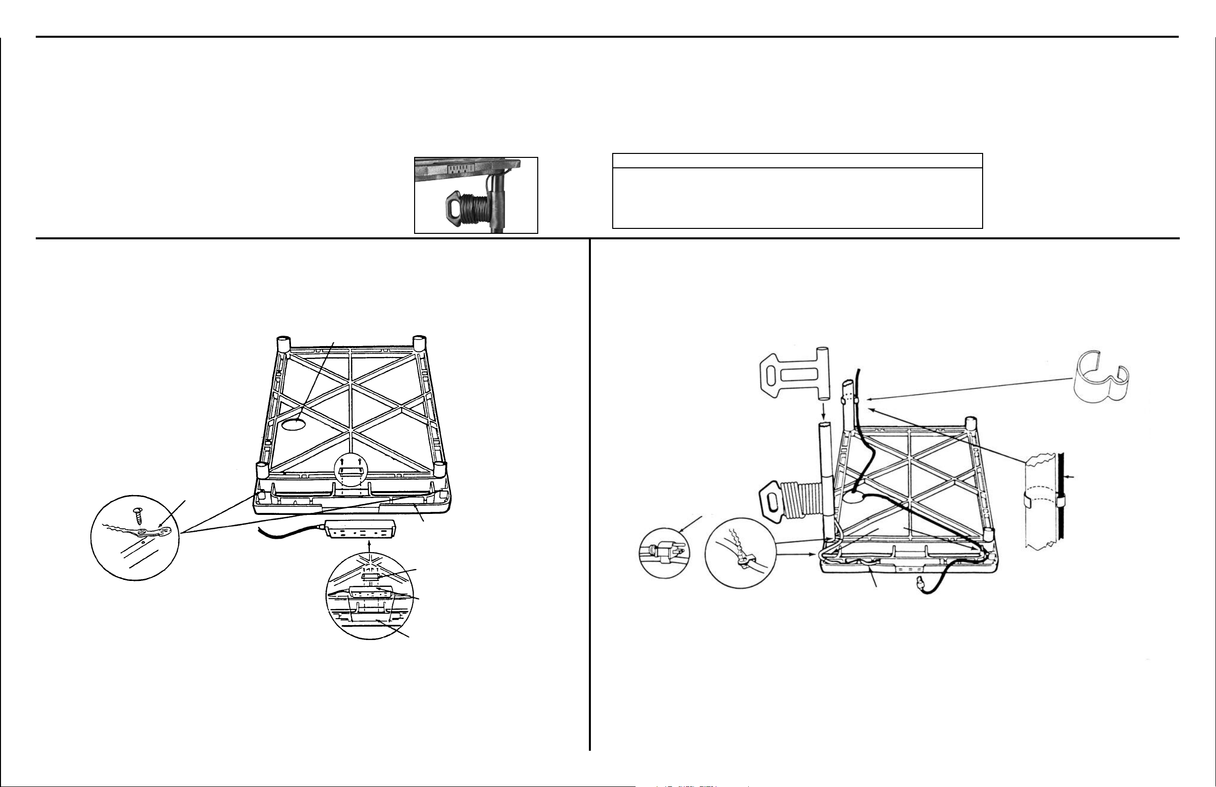
Instructions For - Electrical Assembly
Cable-Track™ Management System and Cord Wrap
ILLUSTRATION A
tant
Impor
The electrical unit should
1.
be assembled first.
Your Endura mobile equipment table incorporates the Cable-Track™
cord management system. This exclusive feature manages electrical
cords, keeping them safely out of the way. This system includes a
3-outlet, 15 foot surge suppressing electric assembly (U.L. and C.S.A.
CABLE GROMMET HOLE
listed) which is built into the safety handle. Please review these instructions carefully to maximize the added safety provided by Luxor’s CableTrack™ cord management system.
Parts List
1 - Surge protected power cord 1 - Power cord retainer clip
1 - Cord wrap 2 - “E”-clips
4 - Cord management ties 4 - Sheet metal screws
ILLUSTRATION B
Install correct siz
top shelf then slide cord wrap
down over leg into position.
e leg on
CORD WRAP
5
Each unit comes complete with two E clips
as shown below. These fit to the legs.
E CLIP
Cord wrap must be installed on leg
before assembly of complete unit.
*See belo
2
Secure power cord plug management ties into starter holes
with sheet metal screws.
w (See Illus. B).
CORD
GEMENT
MANA
TIE
3 PLUG UNIT
3
Firmly seat electric assembly 3 plug unit into
handle plug housing as illustrated. Secure
with power cord plug retaining bracket.
CORD RETAINING
TRACK
WER CORD
PO
PLUG RETAINING
BRACKET
3 PLUG UNIT
PLUG HOUSING
4
Thread power cord through
cord retaining track, secure with
cord management ties by wrapping tie around cord and fastening. Cut off any unnecessary
extra length of tie. Wrap remaining cord around the cord wrap
ket. For safety and new
ac
br
appearance, secure cord plug
to cord by utilizing plug snap.
CORD
MANAGEMENT
TIE
TIES
CORD RETAINING
TRA
CK
6
Position E clip as
shown. Route your
cord going to equipment on lower shelf
through clips for a
safe and organized
cord management
system.
 Loading...