

Page 1
HEAT
OFF
COOL
M
O
INSTALLATION AND OPERATING INSTRUCTIONS
OFF
TX250 SERIES
SMART TEMP
ELECTRONIC THERMOSTAT
Easy as
CAUTION
• Your thermostat is a precision instrument. Please handle it with care.
• Turn off electricity to the appliance before installing or servicing thermostat or any
part of the system. Do not turn electricity back on until work is completed.
• Do not short (jumper) across electric terminals at control on furnace or air
conditioner to test the system. This will damage the thermostat and void your
warranty.
• All wiring must conform to local codes and ordinances.
• This thermostat is designed for use with 24 volt and millivolt systems. The
thermostat should be limited to a maximum of 1.0 amps; higher amperage may
cause damage to the thermostat. If you are in doubt, call your utility company.
Installs Easily
Complete, Easy To Read Programming And Installation Instructions Inside
LUX PRODUCTS CORPORATION • Philadelphia, PA 19112 43374
WARNING: Use Energizer® or DURACELL® Alkaline Batteries Only.
Energizer® is a registered trademark of Eveready Battery Company, Inc.
DURACELL® is a registered trademark of The Gillette Company, Inc.
Choose Heat or CoolSet Day & Time
1–2–3
IMPORTANT!
READ
INSTALLATION
INSTRUCTIONS
FIRST
These instructions may contain information beyond that required for your particular installation.
Please save for future reference.
FEATURES
• The TX250 can be
used with most 24
volt gas, oil or
electric heating
and air
conditioning
systems, singlestage heat pumps
or gas millivolt
heating systems.
It cannot be used
with 120 volt heating
systems or multistage
heat pumps. Ask your
dealer for other LUX
thermostats to
control those
systems.
• The TX250 is
programmable.
There are four
programming periods
per day. Each period can be programmed separately.
• Easy to use Speed Slide.
• You can use the built-in time/temperature programs, or alter them to suit your
schedule. The TX250 provides separate programming for weekdays and weekends
— for both heating and cooling. You can override the programmed temperatures for
as little as one programming period or for an entire vacation.
• In cool weather, when the system switch is set to HEAT, the TX250 may maintain
cooler “set back” room temperatures to save energy. It will then change to warmer
“comfort” settings — automatically, at specified times during the day.
• In warm weather, when the system switch is set to COOL, the TX250 may maintain
warmer “set back” room temperatures to save energy. It will then change to cooler
“comfort” settings — automatically, at specified times during the day.
• A liquid crystal display shows time, day of the week, and room and set
temperatures.
• Temperature swing adjustment lets you fine-tune your system for maximum
comfort and economy.
• A 2 or 5-minute minimum off time in COOL prevents your air conditioning system
from being damaged.
• Two Energizer®or DURACELL® “AA” alkaline batteries (not included) are used to
retain your time and temperature programs.
Thank you for your confidence in our product. To obtain the best results
from your investment, please read these instructions and acquaint yourself with
your purchase before installing your new thermostat. Then follow the
installation procedures, one step at a time. This will save you time and
minimize the chance of damaging the thermostat and the systems it controls.
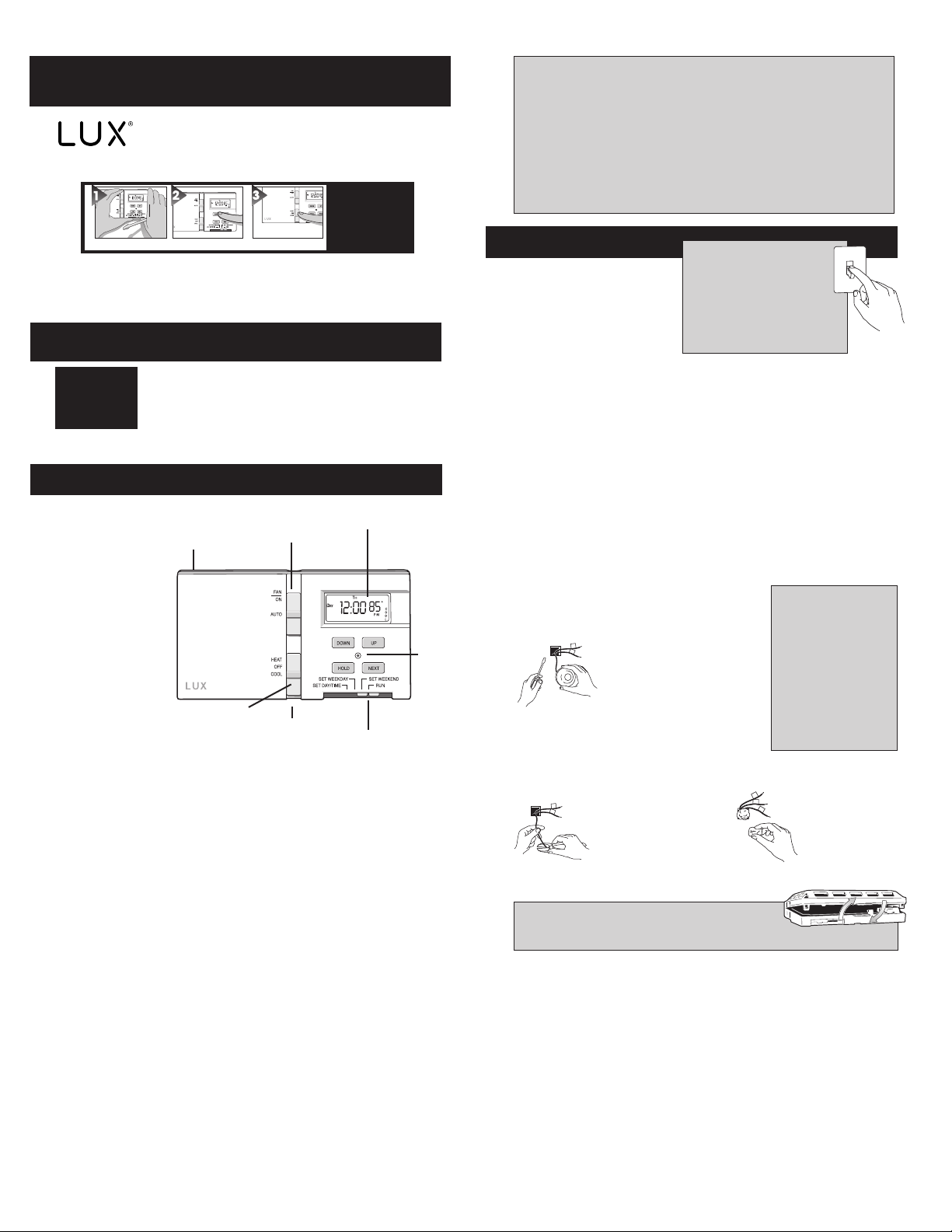
Liquid Crystal
Thermostat
Body
Mode
Switch
Fan Switch
Separator
Tabs
Display
Speed
Slide
Reset
Button
INSTALLATION
Please read all instructions carefully
before beginning installation.
TOOLS REQUIRED
#1 Phillips screwdriver (small)
Drill with 3/16-in. (4.8mm) bit
CAUTION
To avoid electrical shock and
to prevent damage to the
furnace, air conditioner, and
thermostat, disconnect the power
supply before beginning work. This
can be done at the fuse box, at the
circuit breaker, or at the appliance.
THERMOSTAT LOCATION
On replacement installations, mount the new thermostat in place of the old one
unless the conditions listed below suggest otherwise. On new installations, follow
the guidelines listed below.
1. Locate the thermostat on an inside wall, about 5 ft. (1.5m) above the floor, and in
a room that is used often.
2. Do not install it where there are unusual heating conditions, such as: in direct
sunlight; near a lamp, radio, television, radiator, register, or fireplace; near hot
water pipes in a wall; near a stove on the other side of a wall.
3. Do not locate in unusual cooling conditions, such as: on a wall separating an
unheated room; or in a draft from a stairwell, door, or window.
4. Do not locate in a damp area. This can lead to corrosion that will shorten
thermostat life.
5. Do not locate where air circulation is poor, such as: in a corner or an alcove; or
behind an open door.
6. Do not install the unit until all construction work and painting has been completed.
7. This thermostat does not require leveling.
REMOVING THE OLD THERMOSTAT
Switch electricity to the furnace and air conditioner
OFF; then proceed with the following steps.
2. Note the letters printed near the terminals. Attach
labels (enclosed) to each wire for identification.
Remove and label wires one at a time. Make sure the
Y
W
1. Remove cover from old thermostat.
Most are snap-on types and simply
pull off. Some have locking screws
on the side. These must be loosened.
CAUTION
Read instructions carefully
before removing any
wiring from existing
thermostat. Wires must be
labeled before they are
removed. When removing
wires from their terminals,
ignore the color of the
wires since these may not
comply with the standard.
wires do not fall back inside the wall.
3. Loosen all screws on the old thermostat and remove it from the wall.
MOUNTING THE TX250 ON THE WALL
Y
W
1. Strip insulation 3/8 in.
(9.5mm) from wire ends
and clean off any corrosion.
Y
2. Fill wall opening with
W
R
non-combustible
insulation to prevent
drafts from affecting
the thermostat.
3. Cup and hold thermostat body and left tab in place with left hand. Separarte tabs
with right hand.
CAUTION
Be careful not to drop the body or disturb electronic parts.
1© COPYRIGHT 2004 LUX PRODUCTS CORPORATION. ALL RIGHTS RESERVED
Page 2
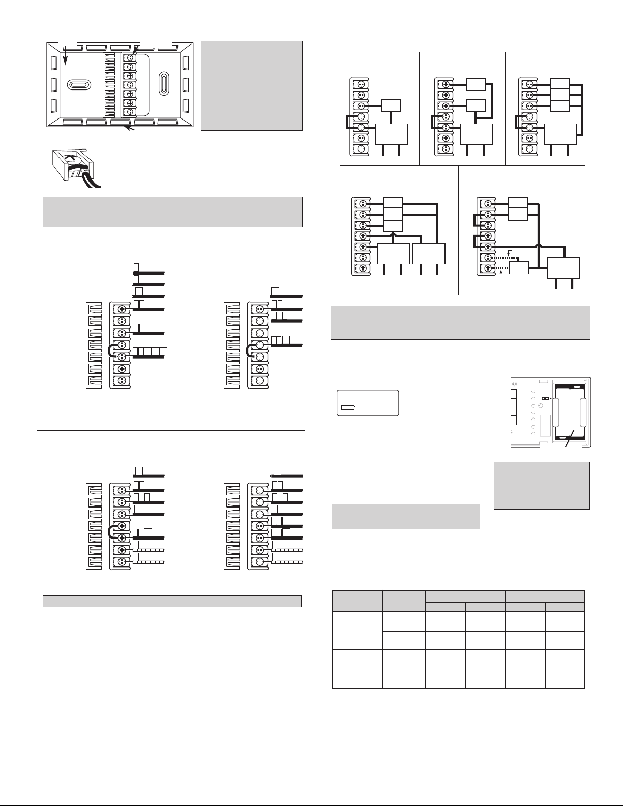
Base
GYWRCRHOB
FAN RELAY
COOLING COMPRESSOR
HEATING CONTROL
COOL TRANSFER
HEATING TRANSFER
DAMPER OR CHANGEOVER
VALVE (Powered in Cool)
DAMPER OR CHANGEOVER
VALVE (Powered in Heat)
If replacing a Honeywell TM-11, tape off wire "R";
connect wire "B" to terminal "RH".
RCR RH
G F
4 H W
5 V
TC
TAPE OFF
HEATING SYSTEMS
GYWRCRHOB
FAN RELAY
COOLING COMPRESSOR
HEATING CONTROL
COOL TRANSFER
HEATING TRANSFER
DAMPER OR CHANGEOVER
VALVE (Powered in Cool)
DAMPER OR CHANGEOVER
VALVE (Powered in Heat)
RC
G F
C Y
V R
TC
TAPE OFF
COOLING SYSTEMS
*
B
TAPE OFF
*
*
If both "Y" and "C" wire are present, tape off "C" wire.
If both "Y" and "C" wire are present, tape off "C" wire. If both "Y" and "C" wire are present, tape off "C" wire.
4- or 5-WIRE WITH ONE TRANSFORMER 5- or 6-WIRE WITH TWO TRANSFORMERS
*
If replacing a Honeywell thermostat with a clock wire "C",
tape off wire "C".
**
C
TAPE OFF
**
GYWRCRHOB
FAN RELAY
COOLING COMPRESSOR
HEATING CONTROL
COOL TRANSFER
HEATING TRANSFER
DAMPER OR CHANGEOVER
VALVE (Powered in Cool)
DAMPER OR CHANGEOVER
VALVE (Powered in Heat)
TC
F G
W
TAPE OFF
OPTIONAL
OPTIONAL
HEATING / COOLING SYSTEMS
GYWRCRHOB
FAN RELAY
COOLING COMPRESSOR
HEATING CONTROL
COOL TRANSFER
HEATING TRANSFER
DAMPER OR CHANGEOVER
VALVE (Powered in Cool)
DAMPER OR CHANGEOVER
VALVE (Powered in Heat)
RC
V R
HEATING / COOLING SYSTEMS
Y C
*
**
O
B
TC
F G
W
TAPE OFF
OPTIONAL
OPTIONAL
RH
4 A
RC
V R
C Y
*
O
B
*
TYPICAL HOOKUP FOR 2-WIRE
24V HEATING SYSTEM AND
MILLIVOLT SYSTEM
24 VAC
TRANSFORMER
OR
THERMOPILE
GAS
VALVE
110
TYPICAL HOOKUP FOR 3-WIRE
HEAT SYSTEM IF THIRD
WIRE IS FAN WIRE
24 VAC
TRANSFORMER
GAS
VALVE
FAN
110
TYPICAL COOLING AND
HEATING SYSTEM
(4-WIRE)
24 VAC
HEAT
TRANSFORMER
GAS
VALVE
FAN
110
COOL
COMP
TYPICAL COOLING AND
HEATING SYSTEM
(5-WIRE)
24 VAC
HEAT
TRANSFORMER
24 VAC
COOL
TRANSFORMER
REMOVE JUMPER BETWEEN "RC" AND "RH"
GAS
VALVE
FAN
110 110
COOL
COMP
TYPICAL SINGLE-STAGE
HEAT PUMP WIRING
ADD JUMPER BETWEEN "Y" AND "W"
ALTERNATE
FAN
COMP
CHANGE
OVER
24 VAC
HEAT
TRANSFORMER
110
ALTERNATE
GYWRCRHOB
GYWRCRHOB
GYWRCRHOB
GYWRCRHOB
GYWRCRHOB
GYWRCRHOB
Terminals
NOTE
If you are mounting the base to
a soft material like plasterboard
or if you are using the old
mounting holes, the screws
may not hold. Drill a 3/16-in.
(4.8mm) hole at each screw
location, and insert the plastic
anchors provided. Then mount
the base as described below.
ATTACHING WIRES
Latch Button
4. Hold the base against the wall, with the wires coming through
wherever it is convenient for wiring. Route the wires to the
terminal block. Position the base for best appearance (to hide
any marks from an old thermostat). Attach the base to the wall
with the two screws provided.
CAUTION
Do not allow wires to touch each other or parts on thermostat. Wires must be trapped between
black spacer and brass terminal. Also, be sure to securely tighten all 7 electrical terminal screws.
WIRING DIAGRAMS
These diagrams below are provided for new installations or unreferenced wires.
If you have an electric system and the blower does not operate after installation, find the
electric/gas heat jumper on the back of the body. Move the jumper to the ELEC position.
INSTALLING BATTERIES/ MAINTENANCE
The TX250 requires batteries to operate your furnace and retain its
programming in memory. Replace the batteries when the REPLACE indicator
appears in the display or at least once a year.
LO BAT
REPLACE BATTERIES WHEN
INDICATOR APPEARS
OR AT LEAST
ONCE A YEAR.
SE
IN
R
1. Remove fresh batteries from their carton.
2. Cup and hold thermostat body and left tab
in place with left hand. Separarte tabs
with right hand.
3. Remove the used batteries.
4.
Install two new Energizer®or DURACELL®"AA"
size alkaline batteries in the battery compartment.
Observe the polarity marking shown in the
compartment. Place body back on wall.
WARNING: Use Energizer®or DURACELL
®
Alkaline Batteries Only.
Installation is now complete. Be sure to turn the power back on to your heating
and /or air conditioning system. If this is the first time you are installing batteries, the
thermostat will display “SUN 12:00 AM”. Within 90 seconds the thermostat will begin
to display the room temperature alternately with the time. To correct the display, see
“Setting the TIME and DAY,” after you set the programs.
When replacing batteries, you
have approximately 1 minute
before programs are lost.
5. Align the top of the body onto
the base and pr
GAS
ELEC
"AA"
Battery
Compartment
NOTE
ess together.
"AA"
PROGRAMMING CHART
DAY PERIOD HEAT COOL
TIME TEMP. TIME TEMP.
MON. MORN
THRU DAY
NOTE
FRI. EVE
SAT. DAY
and EVE
SUN. NIGHT
NIGHT
MORN
2© COPYRIGHT 2004 LUX PRODUCTS CORPORATION. ALL RIGHTS RESERVED
Page 3
HEAT
OFF
COOL
MO
PM
MO
DAY
OVERRIDE
PM
H
E
A
T
OPERATION
NEXT
UP
DOWN
NEXT
UP
DOWN
NEXT
UP
DOWN
NEXT
NEXT
UP
UP
UP
DOWN
DOWN
NEXT
UP
DOWN
NEXT
UP
DOWN
NEXT
UP
DOWNUPDOWN
MO
DAY
HOLD
PM
H
E
A
T
66
HOLD
NEXT
NEXT
HOLD
UP
DOWN
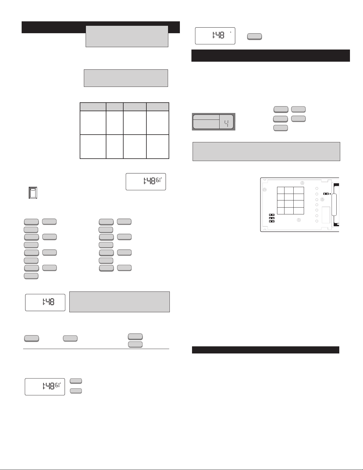
The TX250 alternately displays the
current time and the room
temperature. It also displays the day of
the week and the currently active
program period that is controlling the temperature: MORN, DAY, EVE, or NITE.
The set point temperature will appear in the right side of the display. In the winter, set the
system switch to HEAT to control your heating system. In the summer, set the switch to
COOL to control your air conditioner. In spring and fall or when windows are open, you can
set the system switch OFF.
Setting the FAN switch to AUTO
automatically runs your system’s fan
during heating and cooling. Setting
the FAN switch to ON runs your
system’s fan continuously even without heating or cooling.
This thermostat is “armchair programmable”
You can make any program or setting
changes with the thermostat body off or on
the wall thermostat base.
NOTE
The FAN switch works only if your system
provides a wire for the TX250’s “G” terminal.
THE BUILT-IN ENERGY STAR®PROGRAMS
Push in the RESET key. This
sets the default heating and
cooling programs. To review the
default programs, move the Speed
Slide to SET WEEKDAY or
SET WEEKEND.
You can use the default
programs as shown, or change
them as you wish. Each day is
divided into four periods. Each
period has its own starting time
and temperature.
PROGRAMMING THE TX250
You can change any preset times and/or temperatures to suit your schedules for the
weekday and weekend programs. Each period (Morning, Day,
Evening, and Night) is programmed for HEAT and for COOL.
WEEKDAYS
preprograms DAY 8:00 AM 62° 8:00 AM 85°
WEEKEND DAY 8:00 AM 62° 8:00 AM 85°
preprograms EVE 6:00 PM 70° 6:00 PM 78°
Select HEAT to program the
TX250 for controlling your heater.
Slide the Speed Slide to SET WEEKDAY PROGRAM. To program the weekends SET
WEEKEND. With Slide on SET WEEKDAY PROGRAM, you will see the display above.
To change the start
time for MORN.
To program temperature.
To change the temp.
setting for MORN.
To move to DAY.
To change start time
for DAY.
To program temperature.
To change the temp.
setting for DAY.
To move to EVE.
PERIOD HEAT COOL
MORN 6:00 AM 70° 6:00 AM 78°
EVE 6:00 PM 70° 6:00 PM 78°
NIGHT 10:00 PM 62° 10:00 PM 82°
MORN 6:00 AM 70° 6:00 AM 78°
NIGHT 10:00 PM 62° 10:00 PM 82°
MO TU WE TH FR
MORN
OR Select COOL to program the
TX250 for controlling your air conditioner.
To change the start
time for EVE.
To program temperature.
To change the temp.
setting for EVE.
To move to NIGHT.
To change the start
time for NIGHT.
To program temperature.
To change the temp.
Move Speed Slide to RUN position to
setting for NIGHT.
start the programs.
H
E
A
T
AM
SETTING THE TIME AND DAY
CAUTION
The TX250 is protected against normal static electric discharges.
However, in extremely dry weather you should touch another metal
object before the TX250 to avoid potential loss of programs.
Move the Speed Slide to SET DAY/TIME position. You should see the display pictured
above with a day of the week flashing. When you are finished setting the day and time,
rotate the dial to RUN to return to normal operation or to another position to continue
programming.
To change
current day.
To set current time. The (e.g.
“12:00”) will be flashing.
To change the
current time.
TEMPERATURE HOLD
• Press HOLD. Adjust temperature as
desired with UP/DOWN.
• Temperature setting will not change even
after next program period begins.
• To clear, press HOLD again.
ADVANCED FEATURES
TEMPERATURE SWING
A thermostat works by turning your heating or cooling system on and off whenever the
room temperature varies a certain number of degrees from the set-point temperature. This
variation is the “swing.”
Your system should cycle on about 3 to 6 times per hour. A smaller swing number
increases the number of cycles, so room temperature is more constant. Setting “1” is
approximately 1/4°F. Each increase of 1 value increases the swing by approximately 1/4°F.
A larger swing number decreases the number of cycles, and may save energy in some
cases.
SWING SETTINGS
SET TEMPSWING
WARNING
Making these changes will require you to reset the thermostat. Copy any of your customized
programs onto the blank chart. This will be your reference to re-enter the programs afterwards.
Speed Slide must
be in the run
position
CHANGING FROM °F TO °C AND A 12HR CLOCK TO A 24HR CLOCK
• WARNING: Making these changes will
require you to reset the thermostat. Copy
any of your customized programs onto
the chart below. This will be your
reference to reenter the programs
afterwards.
• Located to the left of the circuit board
are three black jumpers C/F and 24/12H.
• To change to Celsius - remove jumper
- JP2.
• To change to a 24HR clock - remove
jumper- JP1.
• Press the reset key on the front of the
thermostat for changes to take effect.
• Reprogram as necessary.
5 MIN/ 2 MIN MINIMUM ON/OFF TIME
Your thermostat has an internal timer built in to protect your compressor. The timer forces
a minimum on/off time of 5 minutes. You may change this minimum on/off time to 2 minutes.
To accomplish this, remove the jumper labeled JP3. You must press the small reset
button on the face of the thermostat for the changes to take effect.
TECHNICAL SERVICE
If you have any problems installing or using this thermostat, please reread the instructions carefully.
Technical Service is available through our Technical Service Number. If you require assistance, please
call our offices between 8:00 a.m. and 4:30 p.m. Eastern Standard Time, Monday through Friday.
The number is (856) 234-8803 or visit our online technical support at www.luxproducts.com.
WARRANTY
Limited Warranty: If this unit fails because of defects in materials or workmanship within one year of
date of original purchase, LUX will, at its option, repair or replace it. This warranty does not cover
damage by accident, misuse, or failure to follow installation instructions. Implied warranties are limited in
duration to one year from date of original purchase. Some states do not allow limitations on how long an
implied warranty lasts, so the above limitation may not apply to you. Please return malfunctioning or
defective units to the participating retailer from which purchase was made, along with proof of
purchase. Please refer to Technical Service Section before returning thermostat.
Purchaser assumes all risks and liability for incidental and consequential damage resulting from
installation and use of this unit. Some states do not allow the exclusion of incidental or consequential
damages, so the above exclusion may not apply to you. This warranty gives you specific legal rights and
you may also have other rights which vary from state to state. Applicable in the U.S.A. only.
JP3
JP2
JP1
JP3
JP2
JP1
OPEN CLOSE
2MIN
C
24HR
Press together
Press to set.
5MIN
F
12HR
To change
swing
GAS
ELEC
TEMPERATURE OVERRIDE AND
TEMPERATURE HOLD
TEMPORARY
TEMPERATURE OVERRIDE
These features let you change the current
Set Temperature without changing the programs
stored in your thermostat’s memory.
•
Press UP/DOWN to change the current temperature
setting. The OVERRIDE indicator appears on display.
•
The OVERRIDE feature will be automatically canceled
UP
at the start of the next program period.
To cancel OVERRIDE prior to next program period press
•
UP/DOWN until original set temperature
DOWN
appears. OVERRIDE indicator will disappear from display.
3© COPYRIGHT 2004 LUX PRODUCTS CORPORATION. ALL RIGHTS RESERVED
 Loading...