

Page 1
GEO
WiFi THERMOSTAT
GEO
Welcome to your LUX/GEO™ quick-start guide
Your LUX/GEOTM internet connected thermostat puts the control of your comfort in your hands and
you are only 10 easy steps away from installation.
IF AT ANY TIME DURING THE INSTALLATION AND SET-UP PROCESS YOU NEED ADDITIONAL SUPPORT,
VISIT LUX-GEO.COM OR CALL 856.234.8803
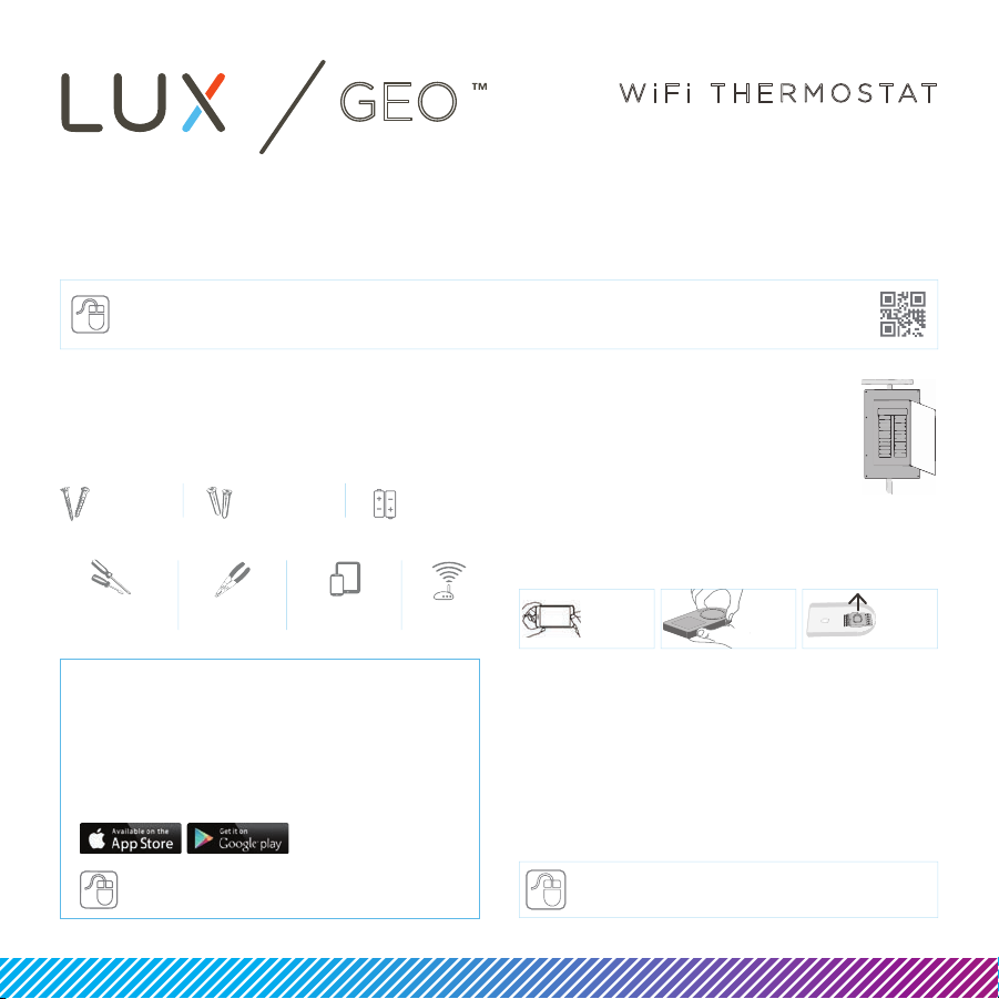
Step 1: Getting started
Locate and gather the following items for ease
of installation
Included:
2 screws
2 wall anchors
Items needed:
phillips & at
head screwdriver
wire stripper
& cutter
WiFi enabled
mobile device
Download App and
Create Your Account
Download your LUX/GEO App
Depending on device type, search the
App store for “LUX GEO” and create
your LUX/GEOTM user account
IF YOU DO NOT HAVE AN iOS OR ANDROID DEVICE,
PLEASE VISIT LUX-GEO.COM.
2-AA Lithium
batteries
WiFi
router
Step 2: Switch power o
IMPORTANT: Turn o the power at
circuit breaker to both your heating
& cooling systems before performing
any wiring.
Step 3: Remove existing
thermostat & install GEOTM
TAKE
PHOTO OF
CURRENT
WIRING
HOLD
AND
PULL TO
OPEN GEO
Remove front of existing thermostat from base
Photograph current wiring for reference
Release wires and mounting screws and
remove base from wall
Open GEO™ from base, pull up on plastic
“cover” between terminal blocks to access
and pull wires through.
Secure GEO base to wall (mounting
hardware & optional wall plate included)
WATCH
OUR VIDEO
DEMO LUX-GEO.COM
REMOVE
TERMINAL
COVER
Page 2
Y1
RESET
W1
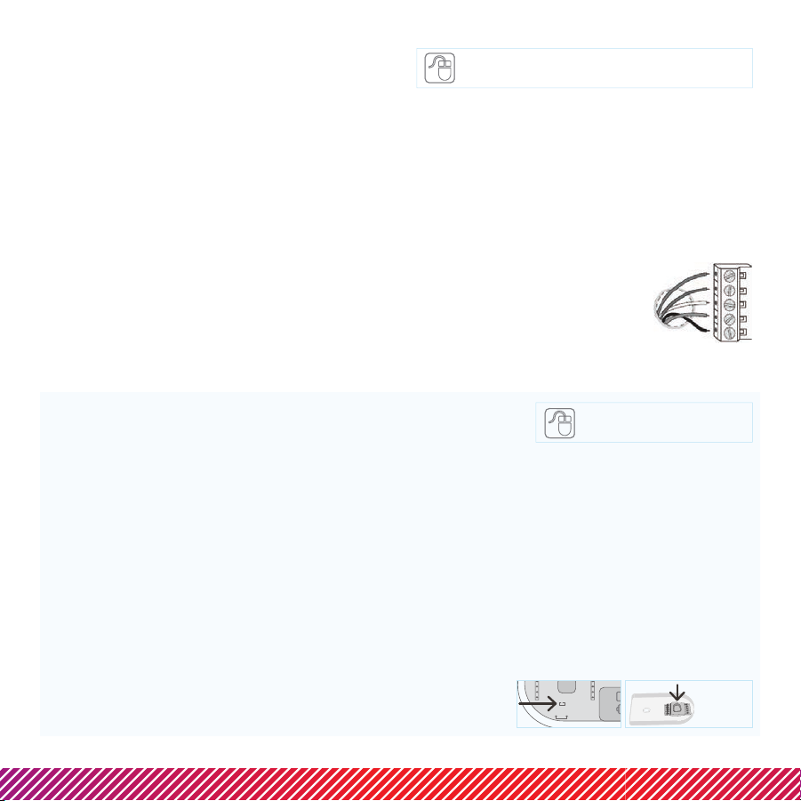
Step 4: Powering & wiring
LUX/GEO
TM
GEOTM needs only 1 of 3 power source options:
C-terminal (Recommended & for optimal performance.
Reference photo from step 3 to confirm C-wire.)
Battery* (2-AA Lithium included)
USB micro-port available on GEOTM
(adapter & cord not included; recommend 1A adapter)
Step 5 provides detail on battery & USB connection
NOTE: System compatibility
For Use On:
Most 24-volt heating and cooling systems
1 or 2 stage heat / 1 or 2 stage cool: gas, oil, or electric
furnace and a/c systems
1 or 2 stage heat / 1 stage cool: heat-pump style systems
2-wire hydronic (hot water) zone valves
Gas Millivolt wall/floor heaters
AS AN ADDED RESOURCE, A GLOSSARY OF TERMS IS
AVAILABLE ON LUX-GEO.COM
*Notice for battery installations:
Batteries should be replaced at least once per year, but
depending on your settings may need to be replaced sooner.
Battery failure could leave property without controlled
heating or cooling. Reliance on battery power is not
recommended with prolonged absence from property.
After installation you can choose to set the
“energy profile” for your GEOTM This energy profile will
determine the delay in GEOTM responding to changes from
the App.
GEOTM should only be used with lithium batteries.
Not For Use On:
120/240 VAC line-
voltage systems
(without a transformer)
Heat pumps that
have (Y2) two
compressor stages
WIRES INSERT INTO SIDE OF
TERMINAL, UNDER SCREWS.
4.1 Wiring Terminal Reference: Conventional
Furnace – gas/oil/electric & air-conditioning*
*for heat pump systems - see section 4.2
FOR A DETAILED WIRING GUIDE
VISIT LUX-GEO.COM.
Referencing your wiring photo & terminal guide below, wire to GEO.
GAS / OIL / ELECTRIC FURNACE and/or AIR CONDITIONING [typical wire color used]
(typical)
RH (or R) = 24(+) VAC Power, Heat [RED]
W1 = 1st Stage Heat [WHITE]
G = Blower Fan [GREEN]
C = 24(-) VAC Common [BLUE]
Y1 = 1st Stage Cool [YELLOW]
(other)
RC = 24(+) VAC Power, Cool
B = Heat Mode Damper
O = Cool Mode Damper
W2 = 2nd Stage Heat
Y2 = 2nd Stage Cool
IMPORTANT: If you have both an RC and RH wire present then
remove the RED RC-RH shorting cap found on inside front of GEOTM.
Wiring is complete - you may return “cover” between terminal blocks.
RC RH
RETURN
TERMINAL
COVER
Page 3

4.2 Wiring Terminal Reference: Heat Pump Systems
RESET
Referencing your wiring photo, attach your thermostat wires to the LUX/GEOTM using your original
wiring letters and the following terminal reference as a guide based upon your system type.
HEAT-PUMP (COMPRESSOR) STYLE HEAT/COOL SYSTEM [typical wire color used]
R (or RC/RH) = 24(+) VAC Power, Cool [RED]
O = Reversing Valve [ORANGE]
Y1 = Heat Pump Outdoor Unit [YELLOW]
G = Blower Fan [GREEN]
W2 = Auxiliary/Emergency Heat [WHITE]
C = 24(-) VAC Common [BLUE]
B** = Reversing Valve (only if no “O” wire- [can vary per each
ie: Rheem/Ruud/Bard systems) installation]
Note: There should NOT be a wire used on the W1 wire connection at terminal.
** IMPORTANT: If you have both an O wire and B wire (ie: Trane system),
please install B to the “C” terminal
Heat Pump systems
(Y1/W1) -
YELLOW cap MUST BE MOVED to sit on both pins.
Wiring is complete – you may return “cover” between terminal blocks.
Y1
W1
TERMINAL
RETURN
COVER
Step 5: Power on
For C-terminal: secure GEOTM front onto base
For battery power: insert 2-AA lithium
batteries & secure GEOTM front onto base
For USB power: place a
flathead screwdriver against
port cover from inside GEOTM
along bottom side – twist &
push out. Plug in Micro USB
and insert into base.
Once GEOTM front has been
secured to base (line up and
firmly push), return power
to system.
INSERT
SCREWDRIVER &
TWIST TO POP OUT
USB COVER
Step 6: Configure system settings
GEOTM will guide you through setup
Rotate the control wheel to navigate
through options and values. To make a
selection, press ; to go back, press .
GEOTM will prompt you to select:
1. Whether heating and/or cooling are
connected.
2. System type (only applies if you have heat).
Note if you wired per section 4.1 you
have a furnace. If you wired per section
4.2 you have a heat pump.
If furnace fan is not operating properly after
installation, change from furnace:gas to
furnace:electric in the settings menu.
WITH GEO SECURE & POWER
ON – THE DISPLAY SHOULD
ILLUMINATE, IF NOT, CHECK
POWER IS BACK ON.
3. The number of stages for heat/cool you have.
Most common is 1 heat/1 cool. Not sure? refer
to our online glossary to learn more.
4. If you have set more than 1 stage of heat or cool,
the OFFSET setting adjusts the stage-2 cut in.
Step 7: If you have not yet downloaded your LUX/GEOTM App–do so now
Page 4

Step 8: Connecting LUX/GEOTM
The recommended set-up of GEOTM requires an iOS or Android device...using another?... Visit
LUX-GEO.com. Set-up follows a series of screen prompts – have your GEOTM and mobile device ready.
8a. Getting ready to connect
You’ve downloaded the
LUX/GEO App, created a
user account and now,
from your GEO, select “yes”
for WiFi setup
GEO will begin scanning but you can move on to 8b.
8b. Connecting GEOTM to your mobile device
Your GEO will show:
“DISCONNECTED”.
Open App and click
+ icon to add device.
When prompted, leave
App & go to your mobile
device’s WiFi settings menu.
Select the WiFi
network that looks like
LUXGEO-xx-xx
iOS iOS
After connecting to
LUXGEO return back to App
Android Android
Page 5

Step 8: Connecting LUX/GEOTM
8c. Select your home WiFi network & enter password
iOS Android
8d. When room temp appears
on GEOTM display, continue by
following prompts on App
Once you see on app and
on GEO - your system is now
successfully connected.
Troubleshoot:
You may need to manually
reconnect your phone to your wifi
network.
If this is unsuccessful – restart
GEO by going to menu/settings/
network and pick up App from
step 8b.
Page 6

Step 9: Custom settings & RadiusTM set-up
RadiusTM is a geofence that allows you to set a geographic “fenced” zone via your mobile device. Using
GPS, RadiusTM (geofencing software) will recognize your approach into or out of the “fenced” area and
trigger your thermostat to adjust to either your “at home” comfort settings or “Away” settings which
provide more ecient energy use. With RadiusTM, geofencing can be set on multiple devices/users and
to your custom needs and can work with or without a thermostat schedule to still save energy when
away from home.
Please note and be assured that your GPS location is NEVER reported or known by LUX Products.
Setting your “fence”
The RadiusTM icon
can be found in
upper right of screen
TIP: IF YOU SET YOUR FENCE FURTHER FROM YOUR HOME THEN YOUR SYSTEM WILL HAVE MORE TIME TO MAKE YOUR HOME
COMFORTABLE BEFORE YOU GET HOME. IF YOU SET THE FENCE CLOSER TO HOME THEN YOU WILL SAVE MORE ENERGY BUT
SOMETIMES YOUR SYSTEM WILL NOT HAVE TIME TO RECOVER BEFORE YOU GET HOME.
IF YOU ARE USING BATTERY POWER, WE RECOMMEND SETTING A LARGER DISTANCE.
Step 10: Enjoy the comfort, peace of mind and flexibility of your LUX/GEO
VISIT OUR ONLINE COMMUNITY FOR INTERESTING ARTICLES AND TIPS FOR SAVING ENERGY AT LUXPRODUCTS.COM. THANK YOU.
LUX/GEO™ is a trademark of LUX Products Corporation. Radius
LUX Products Corporation, Philadelphia, PA 19112 LuxProducts.com ©2015
Ready to set your
fence
Conrm starting
location
TM
is a trademark of EnergyHub, Inc.
Customize your
distance
Complete
TM
thermostat.
53599
 Loading...