

Page 1
INSTALLATION
LUX
LUX
INSTRUCTIONS
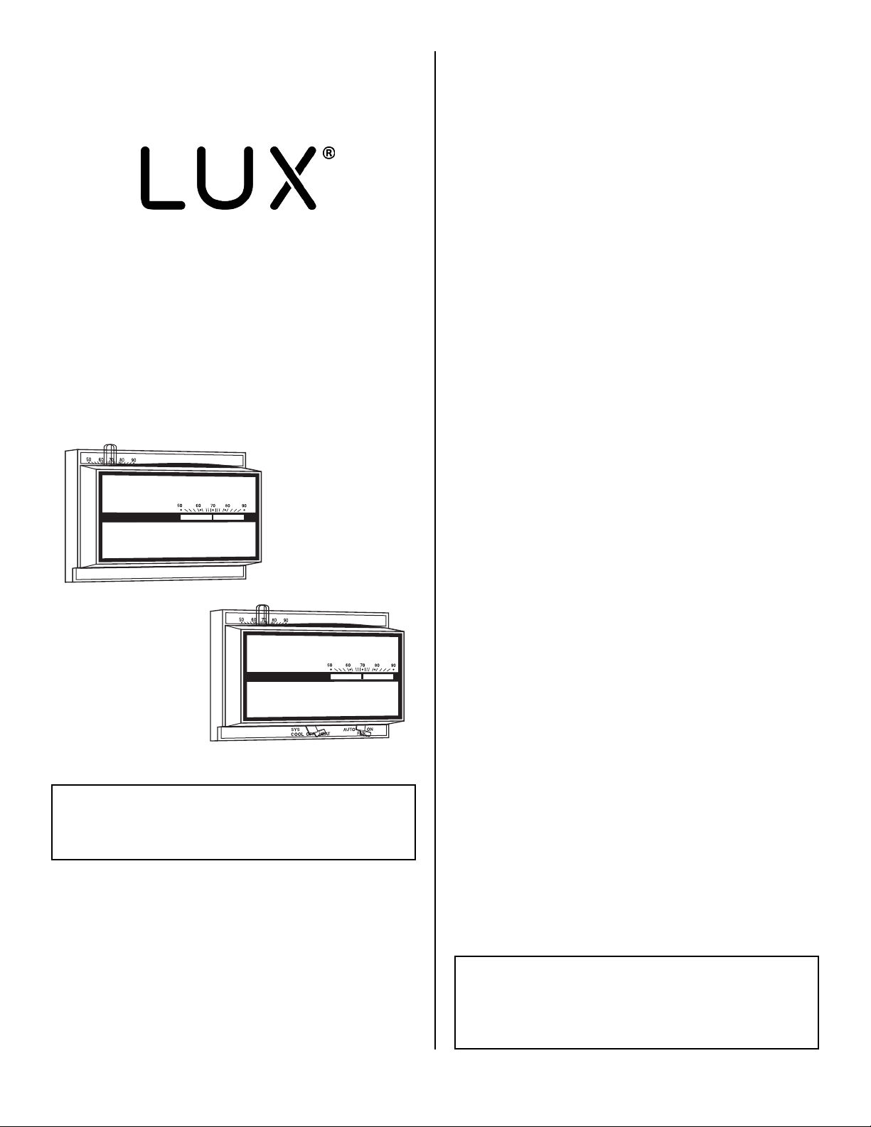
CH200SA & CH400SA
VERSATILE DELUXE LOW
VOLTAGE THERMOSTAT
52010
CH200SA
CH400SA
SELECTING THERMOSTAT LOCATION
The proper location of the room thermostat is most
important to insure that it will provide a comfortable home
temperature. Observe the following general rules when
selecting a location:
1. Locate it about 5 ft. above the floor with a free flow of
air.
2. Install it on a partitioning wall, not on an outside wall.
3. Never expose it to direct light or radiation from lamps,
sun, fireplaces, etc.
4. Avoid locations close to doors that lead outside,
windows, or adjoining outside walls.
5. Avoid locations close to radiators, warm air registers, or
in the direct path of heat from them.
6. Make sure there are no pipes or duct work in that part of
the wall chosen for the thermostat location.
7. Never locate it in a room that is warmer or cooler than
the rest of the home such as kitchen or hallway or on
the opposite side of the wall of a cold or unused room.
8. The living or dining room is normally a good location,
provided there is no cooking range or refrigerator on
opposite side of wall.
INSTALLATION
1. Remove cover from thermostat by pulling outward. Pull
thermostat wires through small holes beside terminal
screws on thermostat base and connect wires to proper
terminal screws per wiring diagrams. Note that on some
models wire leads may be connected to terminal screws
on back of base.
2. The thermostat can either be mounted to a standard
horizontal outlet box or mounted directly to the wall.
Place level on top of thermostat base and mark hole
locations for mounting screws.Push excess wire into
wall or switch box and plug up hole to prevent drafts
from affecting thermostat operation. Then attach
thermostat base loosely to wall with the two screws
provided.
3. Again place level on top of thermostat base to be sure it
is level. Then tighten mounting screws securely and
snap on thermostat cover.
WARNING
Not for use with compressors without time delays.
SPECIFICATIONS
24 Volts A.C.
Electrical Rating: 24 to 30 Volts A.C.
Heat Anticipator: 0.20 to 1.2 Amp. Max.
Cool Anticipator: 0 to 1.0 Amp. Max.
© 2007 LUX PRODUCTS CORPORATION. ALL RIGHTS RESERVED
HEATING ANTICIPATOR
The heating side of this thermostat is equipped with an
adjustable heater. Set heater indicator to match the
current rating of the primary control. The heater may be
adjusted for current ratings from .2 to 1.2 Amp.
Additional adjustments, if necessary, may be made as
follows:
BURNER CYCLES TOO LONG - Set adjustable heater to a
slightly lower dial setting (1/2 division).
BURNER CYCLES TOO SHORT - Set adjustable heater to a
slightly higher dial setting (1/2 division).
WARNING
The Adjustable Heater (Heat Anticipator) WILL BURN OUT if 25V
are applied directly to thermostat by shorting out the gas valve or
primary control during testing or by incorrect wiring.
1
Page 2
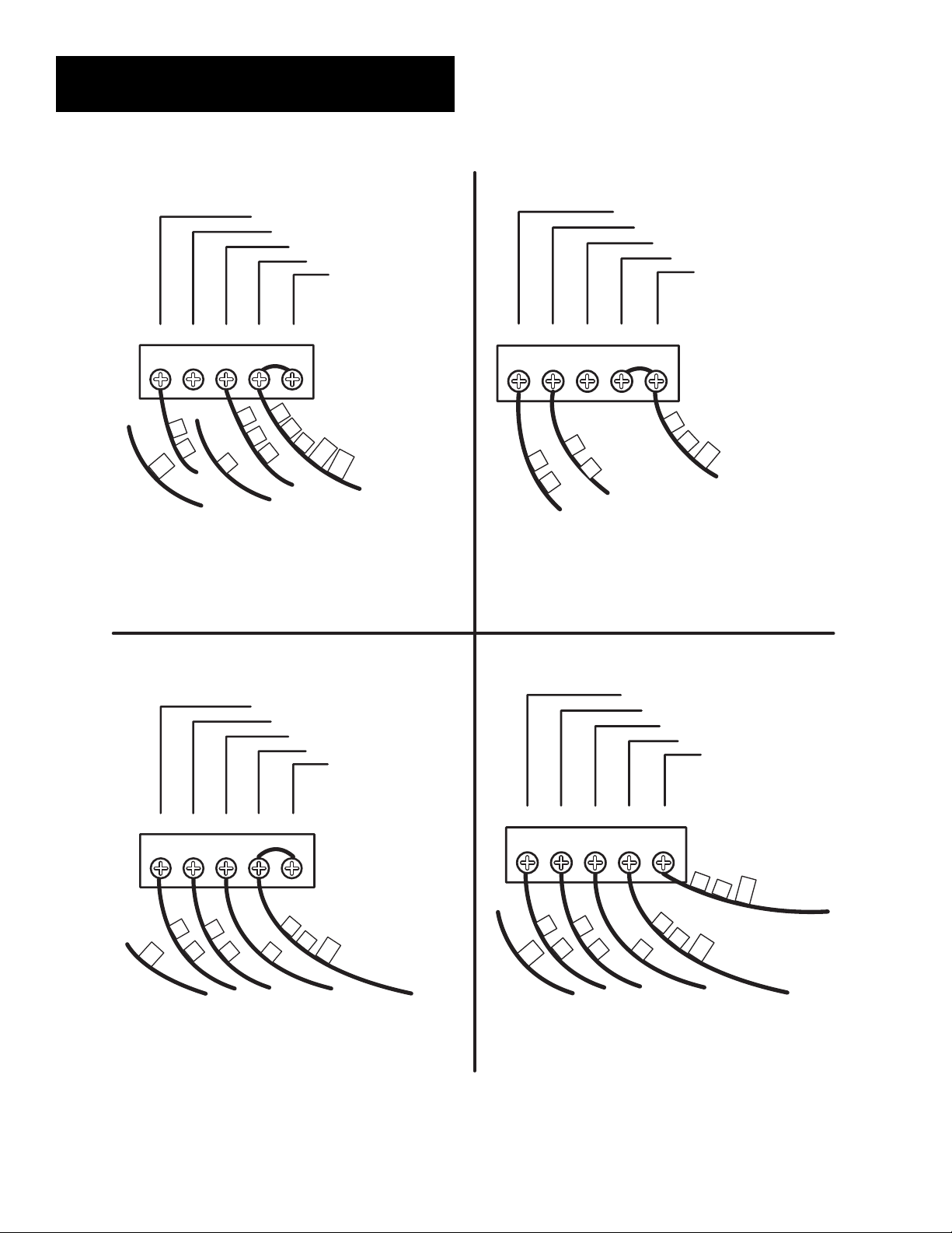
WIRING DIAGRAMS
Heating Systems
FAN RELAY
COOLING COMPRESSOR
HEATING CONTROL
HEATING TRANSFORMER
COOL TRANSFORMER
GYWRHRC
Tape Off
* If r
Tape Off **
G
F
TC
C
eplacing a Honeywell TM-11,
tape of
f wire “R”; connect wire “B”
5
4
V
H
R*
W
RC
RH
to terminal “RH.”
** If r
eplacing a Honeywell thermostat
with a clock wire “C,” tape off wire “C”
Cooling Systems
FAN RELAY
COOLING COMPRESSOR
HEATING CONTROL
HEA
GYWRHRC
*
C
G
Y
F
V
* If both Y and C wir
esent, tape off “C” wire.
pr
TING TRANSFORMER
COOL TRANSFORMER
R
RC
e ar
e
Heating/Cooling Systems
4- or 5-Wire with One Transformer
FAN RELAY
COOLING COMPRESSOR
HEATING CONTROL
GYWRHRC
*
F
Tape Off
TC
Y
G
C
W
* If both Y and C wire are
pr
esent, tape off “C” wire.
HEA
TING TRANSFORMER
COOL TRANSFORMER
V
R
RC
Heating/Cooling Systems
5-or 6- Wire with Two Transformers
GYWRHRC
Tape Off
*
F
C
G
TC
Y
* If both Y and C wire are
present, tape off “C” wire.
FAN RELAY
COOLING COMPRESSOR
HEATING CONTROL
W
TING TRANSFORMER
HEA
COOL TRANSFORMER
V
R
4
A
RH
RC
2
Page 3

These diagrams below are provided for new installations or unreferenced wires.
TYPICAL HOOKUP FOR 2-WIRE
24V HEATING SYSTEM AND
MILLIVOLT SYSTEM
GYWRHRC
GAS
VALVE
24 VAC
TRANSFORMER
OR
THERMOPILE
110
Figure 8
TYPICAL COOLING AND
HEATING SYSTEM
(4-WIRE)
TYPICAL HOOKUP FOR 3-WIRE
HEAT SYSTEM IF THIRD
WIRE IS FAN WIRE
GYWRHRC
GAS
VALVE
FAN
24 VAC
TRANSFORMER
110
Figure 9
TYPICAL COOLING AND
HEATING SYSTEM
(5-WIRE)
GYWRHRC
FAN
GAS
VALVE
COOL
COMP
24 VAC HEAT
TRANSFORMER
110
Figure 10
GYWRHRC
FAN
GAS
VALVE
COOL
COMP
24 VAC HEAT
TRANSFORMER
110
Figure 11
REMOVE
JUMPER
BETWEEN
RH & RC
24 VAC COOL
TRANSFORMER
110
NOTE
if you have an electric system and the blower does not operate after installation, find the factory installed yellow wire
currently attached to the “Y” terminal and move it to the “A” terminal on the sub-base.
3
Page 4

TECHNICAL ASSISTANCE
If you have any problems installing or using this
thermostat, please carefully and thoroughly review the
instruction manual. If you require assistance, please
contact our Technical Assistance Department at 856-2348803 during regular business hours between 8:00AM and
4:30PM Eastern Standard Time, Monday through Friday.
You can also receive technical assistance online anytime
day or night at http://www.luxproducts.com. Our web site
offers you answers to the most common technical
questions, and also permits you to email your questions to
our technical support staff at your convenience.
WARRANTY
Limited Warranty: If this unit fails because of defects in
materials or workmanship within three years of date of
original purchase, LUX Products Corporation will, at its
option, repair or replace it. This warranty does not cover
damage by accident, misuse, or failure to follow installation
instructions. Implied warranties are limited in duration to
three years from date of original purchase. Some states do
not allow limitations on how long an implied warranty lasts,
so the above limitation may not apply to you. Please return
malfunctioning or defective units to the participating retailer
from which purchase was made, along with proof of
purchase. Please refer to "TECHNICAL ASSISTANCE" before
returning thermostat. Purchaser assumes all risks and
liability for incidental and consequential damage resulting
from installation and use of this unit. Some states do not
allow the exclusion of incidental or consequential damages,
so the above exclusion may not apply to you. This warranty
gives you specific legal rights and you may also have other
rights which vary from state to state. Applicable in the
U.S.A. only.
RECYCLING
NOTICE
This product does not contain mercury. However, this
product may replace a unit which contains mercury and
should not be disposed of in the trash. Contact your
local waste management authority for proper disposal
instructions for mercury in a sealed glass tube. If you
have any questions, please call (856) 234-8803
4
 Loading...