

Page 1
3 axis
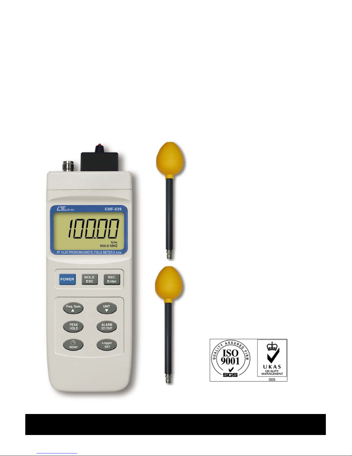
100 KHz to 3 GHz Radio Frequency Radiation Meters
Electromagnetic Field strength measurement
RF ELECTROMAGNETIC
FIELD METER
Model : EMF-839
Your purchase of this RF
EMF METER marks a
step forward for you
into the field of
precision measurement.
Althou
g
h this METER is
a complex and delicate
instrument, its durable
structure will allow
many years of use if
proper operatin
g
techniques are
developed. Please read
the followin
g
instructions carefully
and always keep this
manual within easy
reach.
OPERATION MANUAL
Page 2

TABLE OF CONTENTS
1. FEATURES..................................................................1
2. APPLICATIONS........................................................... 2
3. SAFETY INSTRUCTIONS..............................................
.
2
4. SPECIFICATIONS........................................................4
5. FRONT PANEL DESCRIPTION.......................................7
6. MEASUREMENT CONSIDERATION................................8
7. MEASURING PROCEDURE............................................9
7-1 Buttons instructions..............................................9
7-2 Symbols & units of display....................................
.
10
7-3 Unit Selection...................................................... 11
7-4 Frequency Team Of Selection................................11
7-5 To see the individual axis' measurin
g
EMF value......11
7-6 Alarm Limit Settin
g
and Alarm start........................12
7-7 Data Hold............................................................
.
13
7-8 Data Record (Max., Min. readin
g
)...........................13
7-9 Peak Hold............................................................13
7-10 Data Lo
gg
er.......................................................13
7-10-1 How to recordin
g
data.................................14
7-10-2 How to sendin
g
data...................................15
7-10-3 How to show sample time...........................
.
18
7-10-4 How to show date and time.........................18
Page 3

8. INTERIOR SETTING MODE.......................................... 19
8-1 Check Memory Space.............................................20
8-2 Clear Memory........................................................20
8-3 Date/Time Settin
g
..................................................20
8-4 Sample Time Settin
g
..............................................21
8-5 Auto Power Off Default Settin
g
...............................21
8-6 Escape from the SETTING function.........................21
9. RS232 PC SERIAL INTERFACE......................................
.
22
10. BATTERY REPLACEMENT............................................24
11. SYSTEM RESET......................................................... 24
12. OPTIONAL ACCESSORIES...........................................25
Page 4

1. FEATURES
* 3 Axis probe.
* Radio frequency electromagnetic field tester.
* Wide measuring frequency ranges, 100 KHz to 3 GHz.
* EMF-839 is used for broadband devices of monitoring
the wide range radio frequency electromagnetic field
value.
* For precision measurement consideration, the meter
is included two probes :
EP-04L ( Low frequency Probe, 100 KHz to 100 MHz )
EP-03H ( High frequency Probe, 100 MHz to 3 GHz )
* Unit : V/m, W/m^2, mW/cm^2.
* Alarm setting function can warn the user if the
measuring antenna is too near the strong radiation
sources, the buzzer will sound to remind the user.
* Peak hold function to latch peak value.
* Data hold function to lock the current reading.
* RS232 computer interface.
* Real time data logger, build in clock ( hour-MIN-sec.,
year-month-date ).
* Auto or manual data record, 16,000 Data logger no.
* Wide sampling time adjustment range from one second
to 8 hours 59 minutes 59 seconds.
* Heavy duty hard carry case.
* Large size LCD with contrast adjustment, which can fit
best viewing angle.
* Microcomputer circuit provides special function & offers
high accuracy.
* Powered by 006P DC 9V battery or DC 9V adapter.
1
Page 5

2. APPLICATIONS
This meter is specially developed for measuring or
monitoring electromagnetic field, for example:
cell-phone station, hospital equipment, radar ,
micro-wave oven, radiation work, TV antenna , Radio
station , welding equipment , baking- equipment,
television , computer , factory, laboratory , and other
environment...etc.
3. SAFETY INSTRUCTIONS
Danger
* For worker's safety, be aware that persons with
electromagnetic implant ( e.g. cardiac-pacemarker ) are
subject to especial danger in some case.
* Particular to observe the local safety regulations of the
operator of the equipment.
* Before using the device, it need to know that how to
setting " alarm-limit " value ( refer to page 12 ).
Attention
* Claims by some scientists that long term exposure to
electromagnetic field may be the cause of childhood
leukemia & other forms of cancer.
* Complete answers to any of these and related
questions are not currently available. At the present
time the most common practice is to avoid excess
exposure over long period of time.
2
Page 6
* Complete answers to any of these and related
" Prudent Avoidance " as stated by the Environmental
Protection Agency(EPA) USA is recommended.
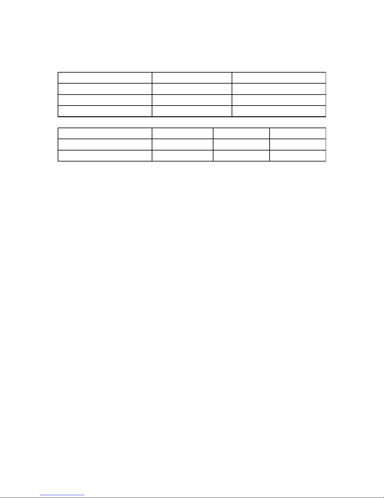
* According to ICNIRP of reference levels to time-varying
electromagnetic fields, The E-field strength levels are:
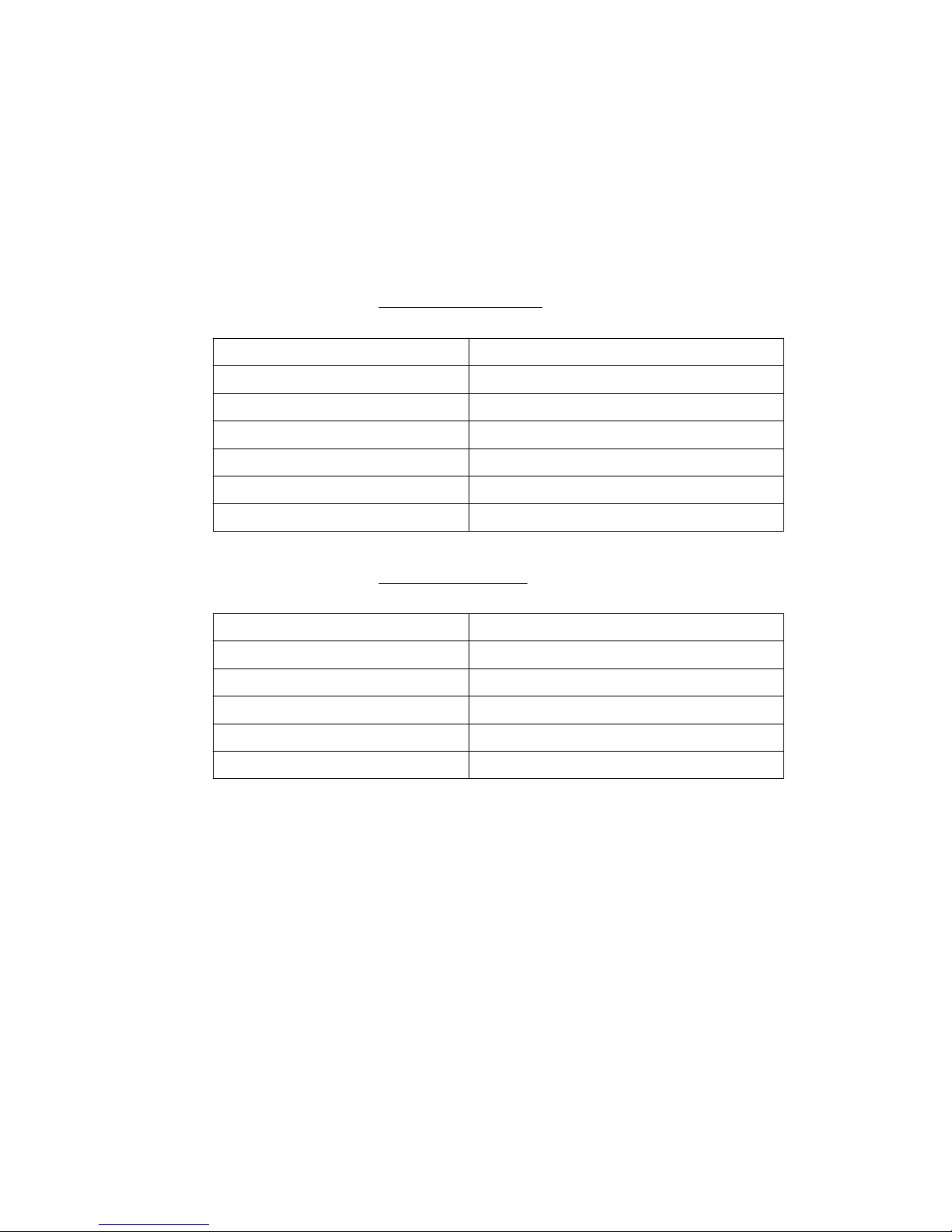
General public
Frequency range e-field strength (V/m)
3 to 150 kHz 87
0.15 to 1 MHz 87
1 to 10 MHz 87/f^1/2
10 to 400 MHz 28
400 to 2000 MHz 1.375 x f^1/2
2 to 300 GHz 61
Occupational
Frequency range e-field strength (V/m)
65 to 1000 kHz 610
1 to 10 MHz 610/f
10 to 400 MHz 61
400 to 2000 MHz 3 x f^1/2
2 to 300 GHz 137
3
Page 7
4. SPECIFICATIONS
4-1 General Specifications
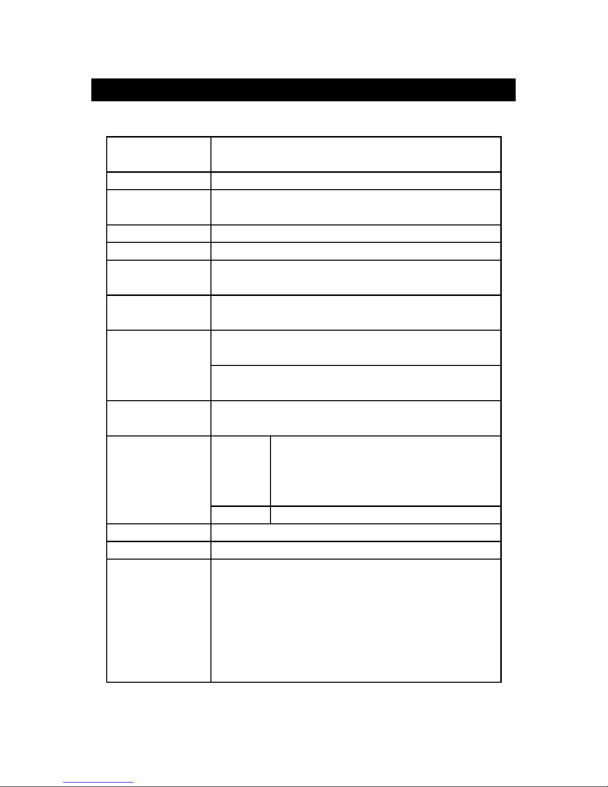
Circuit Custom one-chip of microprocessor LSI
circuit.
Display LCD size : 58 mm x 34 mm.
Measurement V/m, mW/cm^2, W/m^2.
Unit
Accuracy < 2 dB.
Probe structure 3 Axis.
Probe Type EP-03H : 100 MHz to 3 GHz.
Selection EP-04L : 100 kHz to 100 MHz.
Probe Input 50 OHM
Impedance
Frequency EP-03H: 900 MHz, 1 GHz, 1.8 GHz,
Selection 2.4 GHz, 2.45 GHz, 3 GHz.
Points EP-04L: 100kHz, 200kHz, 500kHz, 1MHz,
10MHz, 13.56MHz, 100MHz.
Sensor Semiconductor
Structure
Sampling Time Manual Press the data logger button
of Data Logger once will save data one time.
* Set the sampling time to
0 second
Auto 1 sec to 8 hour 59 min. 59 sec.
Data Hold Freeze the display reading.
REC Function Record Maximum & Minimum value.
Power off Auto shut off saves battery life or
manual off by push button.
* Can default auto power off or manual
power off.
* When default auto power off ,
power will off automatically after
10 min. if no button be pressed.
4
Page 8
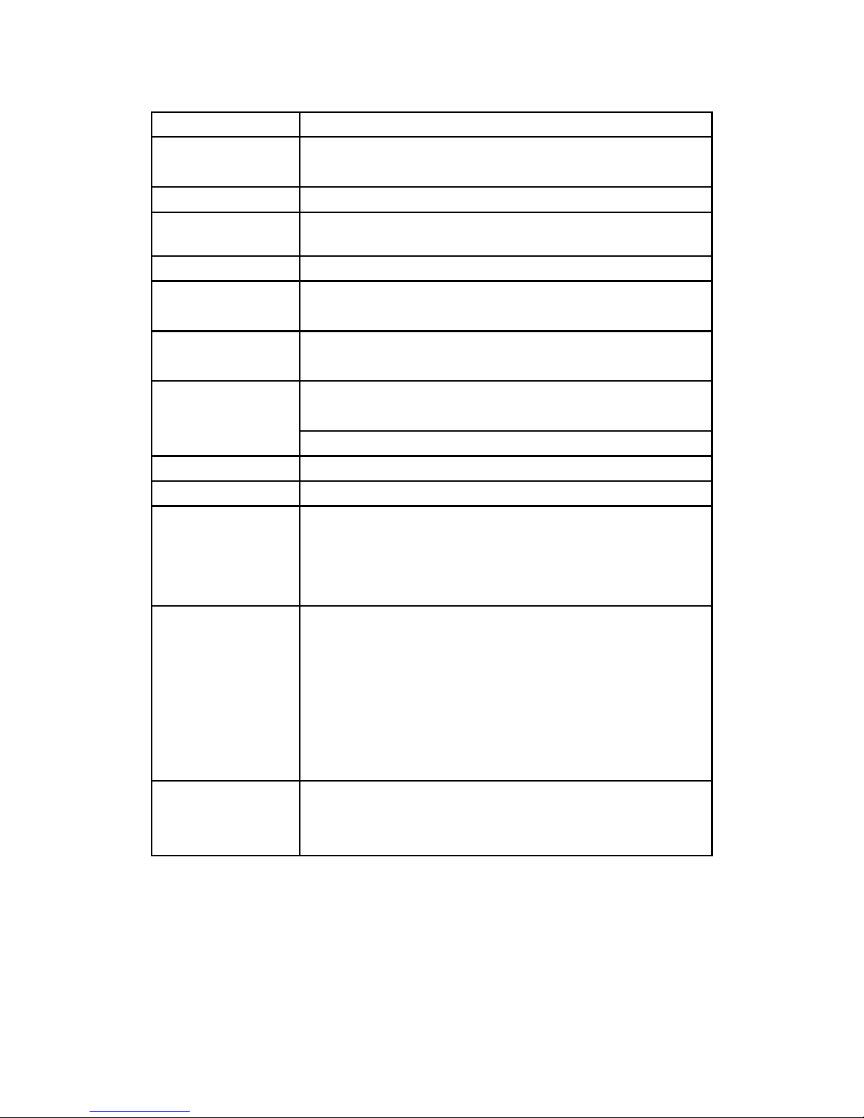
Peak Hold To latch the peak measurement value.
Alarm Setting Buzzer will sound when display over the
setting value.
Sampling Time Approx. 1 second.
Low Battery When display show Low battery
Indicator Indicator, it should chan
g
e the batteries.
Data Output RS 232 PC serial interface.
Operating 0 to 50 .℃
Temperature
Operating Less than 80 %RH.
Humidity
Power Supply DC 9 V battery ( 006P )
* Heavy duty or Alkaline type.
DC 9V adapter input.
Power Current Approx. DC 5.95 mA
Weight 523 g/ 1.16 LB.
Dimension
Main instrument :
200.0 x 76.2 x 36.8 mm
Probe :
70 mm ( diameter) x 290 mm ( length)
Accessories Instruction manual.........................1 PC
Included EP-03H Probe.............................. 1 PC
EP-04L Probe................................
.
1 PC
Memory card for EP-03H................
.
1 PC
Memory card for EP-04L.................1 PC
Hard carrying case.................. 1 PC
DC 9V power adapter.....................1 PC
Optional RS232 cable, UPCB-02.
Accessories USB cable, USB-01.
Data Acquisition software, SW-U801-WIN.
5
Page 9
4-2 Electrical Specifications ( 23 ± 5 )℃
Strength Range Resolution Effective Value
0 to 200.00 V/m 0.01 V/m > 1 V/m
0 to 99.999 W/m^2 0.001 W/m^2 > 0.03 W/m^2
0 to 9.9999 mW/cm^2 0.0001 mW/cm^2 > 0.0003 mW/cm^2
Frequency Range Accuracy Test Point Probe NO.
400 KHz to 100 MHz < 2 dB 30 V/m EP-04L
50 MHz to 2.5 GHz < 2 dB 60 V/m EP-03H
Remark:
* Measurement under other frequency range ( below
400 KHz and over 2.5 GHz ), the reading value just
for reference only.
* For precision measurement consideration, it should
select the " Frequency Team point " near the
frequency value of measuring object.
6
Page 10

5. FRONT PANEL DESCRIPTION
Fig. 1
5-1 Display 5-11 Probe Input Socket
5-2 Power Button 5-12 Probe Memory Card
5-3 Hold / Esc Button 5-13 DC Adapter Input Socket
5-4 REC / Enter Button 5-14 RS-232 Output Terminal
5-5 Freq. Team Select Button 5-15 LCD contrast adj.
5-6 Unit Button 5-16 Battery Cover
5-7 Peak Hold Button 5-17 Stand
5-8 Alarm Set / Start Button 5-18 Reset Button
5-9 Time / Send Button 5-19 Probe Sensing Head
5-10 Logger / Set Button 5-20 Probe Plug
7
Page 11

6. MEASUREMENT CONSIDERATION
1)According to the measuring object's frequency to select
the right probe :
EP-03H probe : 100 MHz to 3 GHz.
EP-04L probe : 100 kHz to 100 MHz.
2)After select convenient the probe, then plug in the
exclusive " Probe Memory Card " ( 5-12, Fig. 1 ) into
the front end socket of meter.
Remark :
* Probe memory card is saved the Probe's
character into the internal memory circuit.
* EP-03H and EP-04L has its own exclusive
" Probe Memory card ", do not plug the
wrong card, otherwise the accuracy will exist
the deviation.
* Make sure to use the " Frequency Team Button " ( 5-5,
Fig. 1 ) to select the convenient frequency value of
measuring object.
However if you don't know the exact
information, the meter will default to 1 GHz
( EP-03H probe ) or 1 MHz ( EP-04L probe )
after power on.
3)The meter is build in the 3 axis ( X, Y, Z ) EMF sensors,
the circuit measure each X, Y, Z sensor's EMF value, then
the CPU will calculate the total EMF value according
the following formula :
X : The EMF value that sensing from the X direction.
Y : The EMF value that sensing from the Y direction.
Z : The EMF value that sensing from the Z direction.
8
Page 12

7. MEASURING PROCEDURE
7 -1 Buttons instructions
Buttons Function
Power Button Press this key to power on or off.
Hold Button Press this key to freeze the reading value.
ESC Button When operate " SET " or " Data logger "
functions, press this key to escape..
REC Button Press this key to record maximum or
minimum value.
Enter Button When operate " SET " or " Data logger "
functions, press this key to enter value.
Freq. Team Press this key to select the convenient
Button object's frequency value.
Unit Button Press this key to select V/m, W/m^2,
mW/cm^2 of strength units.
Peak Hold Press this key to latch peak value during
Button the measurement.
Alarm Set Press this key to setting alarm high/low
/Start Button limit or start alarm function.
Send Button After operate " Data Logger " function,
press this key to send data out.
Logger Set Under " REC " function, press
Button this key to execute data logger.
Press this key to indicate date and time.
9
Page 13

7 -2 Symbols & units of display
Symbol & Function
Unit
V/m Electric field strength
W/m^2 Power density
mW/cm^2 Power density
100kHz....... Frequency team indicates.
..........3GHz
PEAK HOLD Appears on the " PEAK HOLD " function.
It will latch the peak value.
REC Appears on the " REC " function, it will
record maximum and minimum value.
HOLD Appears on the " HOLD " function, it
will freeze the present reading.
Alarm setting Appear on the " Alarm setting Low
low limit limit " function.
Alarm setting Appears on the "Alarm setting High
High limit limit" function.
Alarm setting Appears on the "Alarm setting hysteresis "
hysteresis function.
Sample time Appears on the " Sample time" function,
It indicate sample time that already be set.
Flash unit on Appears on the " START " function, it
the display indicate the ALARM FUNCTION has
starting.
10
Page 14

7-3 Unit Selection
After inserting the " Probe card " ( 5-12, Fig. 1 ) and
connecting probe's plug into the " Probe Input Socket "
( 5-11, Fig. 1 ), use " Unit Button " ( 5-6, Fig. 1) to
select the " V/m, W/m^2, mW/cm^2 ".
7-4 Frequency Teams Selection
1)Use the " Freq. Team Button " ( 5-5, Fig. 1 ) to select
the approx. measuring object frequency value.
EP-03H probe, frequency select points :
900 MHz, 1 GHz, 1.8 GHz,
2.4 GHz, 2.45 GHz, 3 GHz.
EP-04L probe, frequency select points :
100 KHz, 200 KHz, 500 KHz, 1 MHz,
10 MHz, 13.56 MHz, 100 MHz.
2)Make sure to use the " Frequency Team Button " ( 5-5,
Fig. 1 ) to select the convenient frequency value of
measuring object. However if you don't know the exact
information, the meter will default to 1 GHz ( EP-03H
probe ) or 1 MHz ( EP-04L probe ) after power on.
7-5 To see the individual axis' measuring EMF value
Typical the meter is to present the total EMF value of XYZ
direction ( refer to page 8 ), however if intend to see the
individual EMF value of X, Y, Z direction, the procedures are :
1)Power off the meter, use two fingers to press the
" Alarm Button " ( 5-8, Fig. 1 ) and the " Logger Button "
( 5-10, Fig. 1 ) together continuously, then power on the
meter by press the " Power Button " ( 5-2, Fig. 1 ).
After power on, release all the fingers.
2)* Press the " Unit Button " ( 5-6, Fig. 1 ) continuously and
> 2 seconds, the bottom display will show X_axis , then
release the button, the upper display will show the EMF
value of X direction.
11
Page 15

* Press the " Unit Button " ( 5-6, Fig. 1 ) continuously and
> 2 seconds, the bottom display will show X_axis , then
release the button, the upper display will show the EMF
value of X direction.
* Press the " Unit Button " ( 5-6, Fig. 1 ) continuously and
> 2 seconds, the bottom display will show X_axis , then
release the button, the upper display will show the EMF
value of X direction.
* Press the " Unit Button " ( 5-6, Fig. 1 ) continuously and
> 2 seconds, the bottom display will show " V/m " , then
release the button, the upper display will show the total
EMF value of XYZ direction ( refer page 8 ).
7-6 Alarm limit setting and Alarm start
1)Press the "Alarm Button " ( 5-8, Fig. 1) once to start
the alarm function, while the " units " symbol will
flash on the display.
2)Press the " Alarm Button " ( 5-8, Fig. 1 ) once again
to stop the alarm function.
3)Press the " Alarm Button " ( 5-8, Fig. 1 )
continuously and over 2 seconds, the "Alarm low
limit value " will indicate on the lower display, use
the " , Buttons " to adjust the desiring▼▲
low limit value.
4)Press the " Enter Button " ( 5-4, Fig. 1 ) will save the
low limit value and going to adjust the " High limit
value, procedures will similar as above.
5)After finish the " High limit value " adjustment,
press the " Enter Button " ( 5-4, Fig. 1 ) will save the
high limit value and going to adjust the alarm
Hysteresis value, procedures will similar as above.
Upon finish the alarm " Hysteresis value " adjustment,
press the " Enter Button " ( 5-4, Fig. 1 ) will save the data.
6)Press the " ESC Button " ( 5-3, Fig. 1 ) to finish
alarm setting procedures.
12
Page 16

7-7 Data hold
During the measurement, press the " Hold Button " ( 5-3,
Fig. 1 ) once will hold the measured value & the LCD will
indicate a " HOLD " symbol.
Press the " Hold Button " once again will release the data
hold function.
7-8 Data Record ( Max., Min. reading )
* The data record function records the maximum and
minimum readings. Press the " REC Button " ( 5-4, Fig.
1 ) once to start the Data Record function and it
will be a " REC " symbol on the display.
* When the " REC " symbol on the display :
a)Press the " REC Button " ( 5-4, Fig. 1 ) once, the
" REC MAX " symbol along with the maximum value
will appear on the display.
Press the " REC Button " ( 5-4, Fig. 1 ) once again, the
" REC MIN " symbol along with the minimum value.
If intend to delete the maximum ( Minimum ) value,
just press the " Hold Button " ( 5-3, Fig. 1 ) once,
then the display will show the " REC " symbol only &
execute the memory function continuously.
b)To exit the memory record function, just press the "
REC Button " 5-4, Fig. 1 ) 2 seconds continuously at
least. The display will revert to the current reading.
7-9 Peak Hold
Press the " Peak Hold Button " ( 5-7, Fig. 1 ) once to latch
peak value on the display , press once again to defect.
7-10 Data Logger
The data logger function can save 16,000 measuring
data with the clock time ( Real time data logger), build
in clock ( hour-min.-sec., year-month-date ).
13
Page 17

7-10-1 How to recording data
a)If press the Logger Button " ( 5-10, Fig. 1 ) once will
show the sampling time value on the bottom left
display then disappeared.
b)Press the " REC Button " ( 5-4, Fig. 1 ) once to
start the Data Record function and it will be a
" REC " symbol on the display.
c)Auto Data Logger ( Sampling time set from
1 second to 8 hours 59 minutes 59 seconds )
Press the " Logger Button " ( 5-10, Fig. 1 ) once to start
the Auto Data Logger function, at the same the
bottom right display will show the indicator
" Recording.... ", now the Data Logger function is
executed. The upper display will show " DATA "
indicator along with " REC " marker.
d)Manual Data Logger ( Sampling time set to 0
second )
Press the " Logger Button " ( 5-10, Fig. 1 ) once will
save the data one time into the memory, at the same
time the bottom right display will show the indicator
" Recording.... " a while. Now the Data logger function is
executed. The upper display will show " DATA "
indicator along with " REC " marker.
14
Page 18

e)Memory full
Under execute the data logger, if the bottom right
display show the " Full ", it indicate the memory data
already over 16,000 no. and the memory is full.
f) Stop the Data Logger
During the Data Logger function is executed, press
the " Logger Button " ( 5-10 Fig. 1 ) once will stop to
execute the data logger function, the " DATA " indicator
will be disappeared.
If press the " Logger Button " ( 5-10, Fig. 1 ) once
again will continue the Data Logger function.
Remark :
1)
If intend to change the data logger sampling time,
please refer to chapter 8-4., page 21.
2)
If intend to know the space of balance data numbers
into the memory IC, please refer to chapter 8-1, page 19.
3)
If intend to clear the saving data from the memory
please refer to chapter 8-2, page 20.
7-10-2 How to send data
If intend to send the data out from the meter, it
should cancel the " Hold function " and the " Record
function " first. The display will not show the " HOLD "
and the " REC " marker.
Press the " SEND Button " ( 5-9, Fig. 1 ) at least 2
seconds until the bottom right display show
" Transmit mode ", then release the button.
15
Page 19

LCD display will show the fowling screen
alternately.
31.44 ← 28
V/m → V/m
1 Transmit mode xx:xx:xx Transmit mode
Block no. The first Start time Start data
data of of each address of
each block block each block
Use Up Button, Down Button to select the▲▼
different data memory block no. ( 1 to 250 ).
If intend to clear the saving data from the memory
please refer to chapter 8-2, page 20.
The meter can save 16,000 data max. , those
data will saved into 250 memory block max.
* The data that save into one routine Data Logger
procedures ( Press " REC " button , following press
the " Logger " button to save the data, the display
will show the " REC " and " DATA " . After save the
data, press the " Logger " button, following press
the " REC " button will exit the Data Logger
function. The " REC " and " DATA " indicator of LCD
will be disappeared ).
16
Page 20

Data 1
to
Block 1 Data X
↓
Data X+1
to
Block 2 Data Y
↓
..................
..................
↓
Data Z
to
Block 250 Data 16,000
* Until the desired Memory Block no. be selected.
Press the " Send Button " ( 5-9, Fig. 1 ) once, the
data in the Memory Block will send out.
During the data send out, the bottom right display will
show the " Sending Data " indicator. When data
already send out completely, the bottom right display
will show the " Transmit mode " indicator again.
* Press the " ESC Button " ( 5-3, Fig. 1 ) will exit
the data sending function and return to the normal
display.
17
Page 21

Remarks :
* If intend up load the data to the computer,
then should connect the RS232 cable
( optional, model : UPCB-02) and apply the
Data Logger software ( optional, Model :
SW-DL2005 ).
* When sending the data, each time just can
send one Memory Block data out. for example
block 1 data, block 2 data... or block 250 data.
7-10-3 How to show sample time
Press the " Logger Button " ( 5-10, Fig. 1) once then display
will appear sample time.
7-10-4 How to show date and time
Press the " button " ( 5-9, Fig. 1 ) once to indicate
date and time.
18
Page 22

8. INTERIOR SETTING MODE
Press the " SET button " ( 5-10, Fig. 1 ) continuously and
over two seconds, the display will show :
XXXXX Memory space
Press " SET button " once again
Clear memory
XX ESC:N Enter:Y
Press " SET button " once again
Date/Time set
XX:XX:XX ^,v Enter ( > )
Press " SET button " once again
Sample Time
XX:XX:XX ^,v Enter ( > )
Press " SET button " once again
Autopower OFF
XXXXX 1:ON, 0:OFF
Press " SET button " once again
ECS > Finish
Press " ESC " to finish.
or Press " SET button " again to quit.
19
Page 23

8-1 Check Memory Space
To check the balance data numbers that exist into the
memory ( allow memorize data no. ).
XXXXX Memory Space
* XXXXX is the balance data numbers, for example
XXXXX=15417.
8-2 Clear Memory
* To delete the existing save data numbers from the
memory.
* Press ENTER Button once, then press ENTER Button
to confirm.
* Press the ESC Button once to quit and return to
the main measurement manual.
8-3 Date/Time Setting
* Use Up Button, Down Button and ▲▼
Enter ( ) Button to select the expect Date →
( year-month-date ) and the time (HOUR-MIN.-SEC.).
* After finish the Date/Time adjustment,
Press the " Enter Button " , then press the " ESC Button "
will quit and save the clock data into the memory.
20
Page 24

8-4 Sample Time Setting
* Use Up Button, Down Button and Enter ( ) ▲▼ →
Button to select the expect Sample Time ( HOUR-MIN.
-SEC.).
* After finish the Sample Time adjustment,
Press the " Enter Button " once , then press the " ESC Button "
will quit and save the clock data into the memory.
8-5 Auto Power Off Default Setting
* Use Up Button, Down Button to select " 1 " or ▲▼
" 0 ".
1 = Auto power off
0 = Manual power off
* Press the " Enter Button " once , then press the " ESC
Button " to quit.
8-6 Escape from the SETTING function
Press the " ESC Button " once a while will quit and
return to the normal measurement display.
21
Page 25

9. RS232 PC SERIAL INTERFACE
The instrument has RS232 PC serial interface via a 3.5
mm terminal ( 5-14, Fig. 1 ).
The data output is a 16 digit stream which can be
utilized for user's specific application.
A RS232 lead with the following connection will be
required to link the instrument with the PC serial port.
Meter PC
(3.5 mm jack plug) (9W 'D" Connector)
Center Pin.............................Pin 4
Ground/shield..........................Pin 2
2.2 K
resister
Pin 5
The 16 digits data stream will be displayed in the
following format :
D15 D14 D13 D12 D11 D10 D9 D8 D7 D6 D5 D4 D3 D2 D1 D0
22
Page 26

Each digit indicates the following status :
D0 End Word = 0D
D1 & D8 Display reading, D1 = LSD, D8 = MSD
For example :
If the display reading is 1234, then D8 to
D1 is : 00001234
D9 Decimal Point(DP), position from right to the
left
0 = No DP, 1= 1 DP, 2 = 2 DP, 3 = 3 DP
D10 Polarity
0 = Positive 1 = Negative
D11 & Annunciator for Display
D12 W/m^2=A9 mW/cm^2 = A8 V/m = A7
D13 When send the upper display data = 1
When send the lower display data = 2
D14 4
D15 Start Word = 02
RS232 setting
Baud rate 9600
Parity No parity
Data bit no. 8 Data bits
Stop bit 1 Stop bit
23
Page 27

10. BATTERY REPLACEMENT
When the left corner of LCD display show " ", it
is necessary to replace the batteries ( 006P ).
1)Slide the " Battery Cover " ( 5-16, Fig. 1 ) away from the
instrument and remove the battery.
2)Replace with batteries ( 006P ) and reinstate the cover.
3)Make sure the battery cover is secured after changing
the battery.
11. SYSTEM RESET
If the meter happen the troubles such as :
CPU system is garbled ( for example, the key button can
not be operated..... ).
Then make the system RESET will fix the problem.
The system RESET procedures will be either following
method :
During the Power On, used a pin tool to push
the " System Reset " button ( 5-18, Fig. 1 ) once.
24
Page 28

12. OPTIONAL ACCESSORIES
RS232 cable * Computer interface cable.
UPCB-02 * Used to connect the meter to
the computer ( COM port ).
USB cable * Computer interface cable.
USB-01 * Used to connect the meter to
the computer ( USB port ).
Data Acquisition * The SW-U801-WIN is a multi
software displays ( 1/2/4/6/8 displays )
SW-U801WIN powerful application software,
provides the functions of data
logging system, text display,
angular display, chart display,
data recorder high/low limit, data
query, text report, chart report..
.xxx.mdb data file can be
retrieved for EXCEL, ACESS..,
wide intelligent applications.
25
0711-EMF839
 Loading...