

Page 1
Three axis ( X, Y, Z ) electromagnetic
field measurement
3 D EMF TESTE
R
Model : EMF-828
Page 2

TABLE OF CONTENTS
1. FEATURES...............................................................1
2. APPLICATIONS........................................................
.
2
3. CAUTION OF ELECTROMAGNETIC FIELD
EXPOSURE.............................................................. 2
4. SPECIFICATIONS.....................................................3
5. FRONT PANEL DESCRIPTION....................................5
5-1 Display............................................................
.
5
5-2 Power button................................................... 5
5-3 Hold button.....................................................
.
5
5-4 XYZ axis select button......................................
.
5
5-5 Unit button......................................................
.
5
5-6 Range button...................................................5
5-7 Battery compartment/Cover..............................5
5-8 Stand..............................................................
.
5
5-9 Probe input socket ..........................................
.
5
5-10 Probe plug ......................................................
.
5
5-11 Probe handle....................................................5
5-12 Probe sensing head..........................................
.
5
6. MEASURING PROCEDURE..........................................6
7. RECOMMENDATION..................................................7
8. BATTERY REPLACEMENT...........................................7
Page 3

1. FEATURES
* Three axis ( X, Y, Z direction ) electromagnetic
field measurement.
* The EMF tester is designed to provide user a quick,
reliable and easy way to measure electromagnetic
field radiation levels around power lines, electrical
appliances and industrial devices.
* Wide measuring ranges, 3 ranges of 20 micro Tesla,
200 micro Tesla & 2000 micro Tesla.
* The EMF tester is a cost effective, hand-held
instrument designed and calibrated to measure
electromagnetic field radiation at wide bandwidths
from 30 Hz to 300 Hz.
* LCD display, jumbo digit size.
* Data hold.
* Separate probe, easy operation.
* DC 9V battery power supply.
* Hard case included.
1
Page 4

2. APPLICATIONS
This EMF tester is specifically designed to determine the
magnitude of electromagnetic field radiation generated
by power lines, computer's monitor, TV sets, video
machinery and many other similar devices.
3. CAUTION OF
ELECTROMAGNETIC FIELD
EXPOSURE
Claims by some scientists that long term exposure to
electromagnetic field may be the cause of childhood
leukemia & other forms of cancer.
Complete answers to any of these and related
questions are not currently available. At the present
time the most common practice is to avoid excess
exposure over long period of time.
"Prudent Avoidance" as stated by the Environmental
Protection Agency(EPA) USA is recommended.
2
Page 5

4. SPECIFICATIONS
Display LCD, 3 1/2 digits.
LCD size : 55 mm x 47 mm.
Max. indication 1999 counts.
With display units.
Range /
micro Tesla :
Resolution 20 micro Tesla/0.01 micro Tesla
200 micro Tesla/0.1 micro Tesla
2000 micro Tesla/1 micro Tesla
mili-Gauss :
200 mili-Gauss/0.1 mili-Gauss
2,000 mili-Gauss/1 mili-Gauss
20,000 mili-Gauss/10 mili-Gauss
Number of Axis Three axis ( X, Y, Z direction ).
Axis selected by push button.
Band width 30 Hz to 300 Hz.
Accuracy ± (4 % + 3 d)
@ 20 micro Tesla range
@ 200 mili-Gauss range
± (5 % + 3 d)
@ 200 micro Tesla range.
@ 2,000 mili-Gauss range
± (10 % + 5 d)
@ 2,000 micro Tesla range.
@ 20,000 mili-Gauss range
* Spec. accuracy tested under 50 Hz
or 60 Hz.
* Spec. tested under the environment
RF Field Strength less than 3 V/M &
frequency less than the 30 MHz only.
3
Page 6

Over-input Display shows " 1 " .
Sampling Time Approx. 0.4 second.
Battery DC 9 V battery (006P, 6F22).
Power Current Approx. DC 2.7 mA.
Operating Temp. 0 to 50 ( 32 to 122 ). ℃℉
Operating Less than 85 %RH.
Humidity
Weight 460 g/1.01 LB (including battery).
@ Including Probe and battery
Dimension Main meter :
195 x 68 x 30 mm
( 7.6 x 2.6 x 1.2 inch )
Probe :
70 x 58 x 220 mm
( 2.8 x 2.3 x 8.7 inch ).
@ Sensor probe head : 70 x 58 mm.
Probe Cable 930 mm.
Length
Accessories Operation Manual....................... 1 PC
Included Carrying case.............................
.
1 PC
4
Page 7

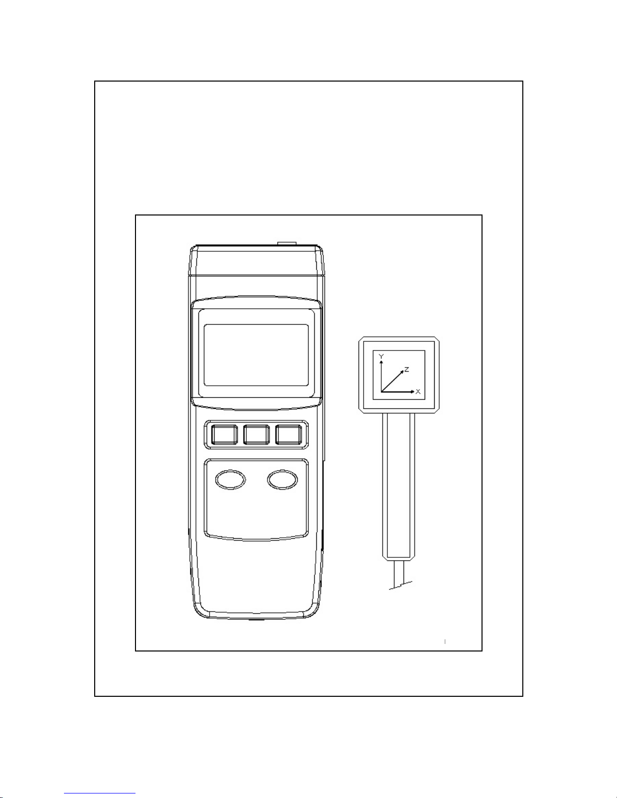
5. FRONT PANEL DESCRIPTION
Fig. 1
5-1 Display
5-2 Power button
5-3 Hold button
5-4 XYZ axis select button
5-5 Unit button
5-6 Range button
5-7 Battery compartment/Cover
5-8 Stand
5-9 Probe input socket
5-10 Probe plug
5-11 Probe handle
5-12 Probe sensing head
5
Page 8

6. MEASURING PROCEDURE
1)Power ON the meter by pushing the " Power button "
( 5-2, Fig. 1 ).
2)Select the desired unit ( micro Tesla or mili-Gauss )
by pushing the " Unit button " ( 5-5, Fig. 1 ).
3)Use the " Range button " ( 5-6, Fig. 1 ) to select the
suitable range. For the unknown EMF measurement,
start with the highest range and keep decreasing until
the higher resolution's reading is obtained.
4)Hold the " Probe handle " ( 5-11, Fig. 1 ), move the
" Probe sensing head " ( 5-12, Fig. 1 ) slowly towards
to the object under measurement until it is physically
touched.
5)Use the " XYZ axis select button " ( 5-4, Fig. 1 ) to
select the EMF value in the X, Y or Z axis.
Note :
@
Due to the electromagnetic interference of the
environment, the display reading may show
small values before testing, for example less
than 0.05 micro Tesla. This is not malfunction of
the tester.
@
If the object under measurement is turned off
during the measurement, the EMF tester
reading should then return to zero, unless a
field from other sources are detected.
6)During the measurement, if push the " Hold button "
( 5-3, Fig. 1 ) will freeze the display value. Push the
" Hold button " again will release the Hold function.
6
Page 9
7. RECOMMENDATION
It is recommended to measure the presence of the
electromagnetic field inside and outside of your home
and business locations regularly.
As "hot spots" are detected by the EMF tester,
re-arrangement of the living and working areas is
lightly recommended. Always try the best to avoid long
term exposure to strong electromagnetic field.
8. BATTERY REPLACEMENT
1)
When the left corner of LCD display show " ", it
is necessary to replace the battery. However, in-spec.
measurement may still be made for several hours after
low battery indicator appears before the instrument
become inaccurate.
2)Slide the " Battery Cover " ( 5-7, Fig. 1 ) away from the
instrument and remove the battery.
3)Replace with 9V battery ( Alkaline or Heavy duty type )
and reinstate the cover.
4)Make sure the battery cover is secured after changing
the battery.
7
0412-EMF828
 Loading...