

Page 1
EEccooSSyysstteemm®®PPrrooggrraammmmeerr
||
PPrrooggrraammmmiinngg GGuuiiddee
VVeerrssiioonn 11..5588
Page 2

Page 3

Contents
Section 1: Introduction
What is EcoSystem®?. . . . . . . . . . . . . . . . . . . . . . . . . . . . . . . . . . 3
The EcoSystem
® Bus . . . . . . . . . . . . . . . . . . . . . . . . . . . . . . . . . . 3
EcoSystem
® Programming . . . . . . . . . . . . . . . . . . . . . . . . . . . . . . 3
Transmitting to Control Devices with IR Receivers . . . . . . . . . . . . . 4
Section 2: Getting Familiar with the Programmer
Logging In . . . . . . . . . . . . . . . . . . . . . . . . . . . . . . . . . . . . . . . . . . 6
Making Screen Selections . . . . . . . . . . . . . . . . . . . . . . . . . . . . . . 6
Control Device Icons . . . . . . . . . . . . . . . . . . . . . . . . . . . . . . . . . . 7
Programming Screen Components . . . . . . . . . . . . . . . . . . . . . . . . 7
Prompt Screens . . . . . . . . . . . . . . . . . . . . . . . . . . . . . . . . . . . . . . 8
Information Screens . . . . . . . . . . . . . . . . . . . . . . . . . . . . . . . . . . . 8
Charging the Programmer . . . . . . . . . . . . . . . . . . . . . . . . . . . . . . . 9
Logging Out . . . . . . . . . . . . . . . . . . . . . . . . . . . . . . . . . . . . . . . . . 9
Section 3: Programming Your System
Typical Programming Workflow . . . . . . . . . . . . . . . . . . . . . . . . . . 10
How an EcoSystem
® Bus Prioritizes Inputs . . . . . . . . . . . . . . . . . 11
Addressing the System. . . . . . . . . . . . . . . . . . . . . . . . . . . . . . . . 12
Configuring Areas . . . . . . . . . . . . . . . . . . . . . . . . . . . . . . . . . . . . 14
Configuring Fixture Groups . . . . . . . . . . . . . . . . . . . . . . . . . . . . . 16
Setting Light Levels for Daylight Sensors . . . . . . . . . . . . . . . . . . . 18
Setting Light Levels for Occupant Sensors . . . . . . . . . . . . . . . . . 20
Setting Light Levels for Contact Closures . . . . . . . . . . . . . . . . . . 22
Setting an Additional Timeout Period for Occupant Sensors . . . . . 24
Setting Up Scenes for Wall Controls . . . . . . . . . . . . . . . . . . . . . . 26
Configuring Ballasts . . . . . . . . . . . . . . . . . . . . . . . . . . . . . . . . . . 28
Setting a Ballast’s High End Trim . . . . . . . . . . . . . . . . . . . . . . . . . 29
Setting a Ballast’s Emergency Level. . . . . . . . . . . . . . . . . . . . . . . 30
Seasoning New Fluorescent Lamps . . . . . . . . . . . . . . . . . . . . . . 31
Page 4

2 EcoSystem® Programmer
Configuring BMJ / XPJ Settings . . . . . . . . . . . . . . . . . . . . . . . . . 32
Setting the XPJ On and Off Level . . . . . . . . . . . . . . . . . . . . . . . . 33
Setting the Gain . . . . . . . . . . . . . . . . . . . . . . . . . . . . . . . . . . . . . 34
Setting XPJ or BMJ Mode. . . . . . . . . . . . . . . . . . . . . . . . . . . . . . 35
Limiting Restrikes . . . . . . . . . . . . . . . . . . . . . . . . . . . . . . . . . . . . 36
Setting Occupied and Unoccupied Levels. . . . . . . . . . . . . . . . . . 37
Setting Egress Levels . . . . . . . . . . . . . . . . . . . . . . . . . . . . . . . . . 38
Setting Daylight Low End . . . . . . . . . . . . . . . . . . . . . . . . . . . . . . 39
Setting Daylight Off Delay . . . . . . . . . . . . . . . . . . . . . . . . . . . . . . 40
Configuring Contact Closures . . . . . . . . . . . . . . . . . . . . . . . . . . . 41
Setting the Contact Closure Mode . . . . . . . . . . . . . . . . . . . . . . . 42
Setting the Demand Response Level. . . . . . . . . . . . . . . . . . . . . . 43
Setting the Contact Closure Occupied or Unoccupied Level . . . . 44
Setting the Contact Closure Occupancy Timeout. . . . . . . . . . . . . 45
Section 4: Stand-Alone Programming
Accessing the Stand-Alone Programming Menu . . . . . . . . . . . . . 47
Setting Stand-Alone Emergency Level . . . . . . . . . . . . . . . . . . . . . 48
Setting Stand-Alone High End Trim . . . . . . . . . . . . . . . . . . . . . . . 49
Stand-Alone Lamp Seasoning. . . . . . . . . . . . . . . . . . . . . . . . . . . 50
Stand-Alone Daylight Sensor Setup. . . . . . . . . . . . . . . . . . . . . . . 51
Stand-Alone Occupant Sensor Setup . . . . . . . . . . . . . . . . . . . . . 52
Stand-Alone XPJ Setup . . . . . . . . . . . . . . . . . . . . . . . . . . . . . . . 53
3 Wire Input . . . . . . . . . . . . . . . . . . . . . . . . . . . . . . . . . . . . . . . . 54
Section 5: Maintaining Your System
Manually Adjusting the Light Level . . . . . . . . . . . . . . . . . . . . . . . . 56
Replacing the Bus Supply. . . . . . . . . . . . . . . . . . . . . . . . . . . . . . 57
Replacing Ballasts . . . . . . . . . . . . . . . . . . . . . . . . . . . . . . . . . . . 58
Addressing New Ballasts . . . . . . . . . . . . . . . . . . . . . . . . . . . . . . 60
Automatic Ballast Replacement . . . . . . . . . . . . . . . . . . . . . . . . . . 61
Resetting the Entire System to Factory Defaults . . . . . . . . . . . . . . 62
Resetting a Ballast to Factory Defaults. . . . . . . . . . . . . . . . . . . . . 63
EcoSystem
® Programmer Version Check . . . . . . . . . . . . . . . . . . 64
Index
Page 5

Introduction
What is EcoSystem®?
EcoSystem lighting control systems are capable of controlling
various lighting sources through automated and manual dimming.
The automatic light controls include motion sensors and daylight
sensors, which monitor a space and appropriately adjust the light to
avoid wasted energy and improve the work environment. The
manual controls of the system include wall dimmers and handheld
remote controls, which allow personal interaction with the lighting by
the people in the space. EcoSystem can also work together with the
security, HVAC, and other building management systems to provide
the appropriate lighting for every situation.
The EcoSystem® Bus
EcoSystem ballasts can be connected to one another to create a
system of up to 64 ballasts. Any infrared (IR) receiver, sensor, or wall
control connected to a ballast can communicate with any or all
fixtures on the bus. Subsystems, called groups, are configured and
programmed using the handheld programmer.
Systems using more than one EcoSystem ballast, or ballast module,
require an EcoSystem bus power supply. This component powers
the communication bus between devices, and is capable of
supporting up to 64 ballasts or ballast modules, 32 occupant
sensors, 64 wall controls or infrared (IR) receivers, and 16 daylight
sensors.
EcoSystem® Programming
EcoSystem is programmed using the handheld EcoSystem
programmer. Using a stylus, users make onscreen selections and
transmit programming instructions via infrared, similar to a TV remote.
1
Page 6

4 EcoSystem® Programmer
Transmitting to Control Devices with IR Receivers
Programming information is transmitted wirelessly from the
EcoSystem programmer to any sensor or control with an integrated
IR receiver. When programming, stand within 8 feet (2.4 meters) of
the sensor or control and point the top of the programmer directly at
it.
Regardless of what function is being performed, the system can be
accessed through any IR receiver. For example, it is not necessary
to point the programmer at the daylight sensor being programmed if
a keypad provides more convenient access.
Keypads and IR receivers have LEDs that blink when programming
messages are transmitted.
If the device does not receive the signal, move closer to the device
or adjust the angle of the programmer. It is also important to ensure
that the programmer battery is charged and has enough strength to
transmit the signal to the device.
NOTE: Occupant sensors do not have integrated IR receivers.
Page 7
Getting Familiar
with the Programmer
This section describes how to perform basic system operations.
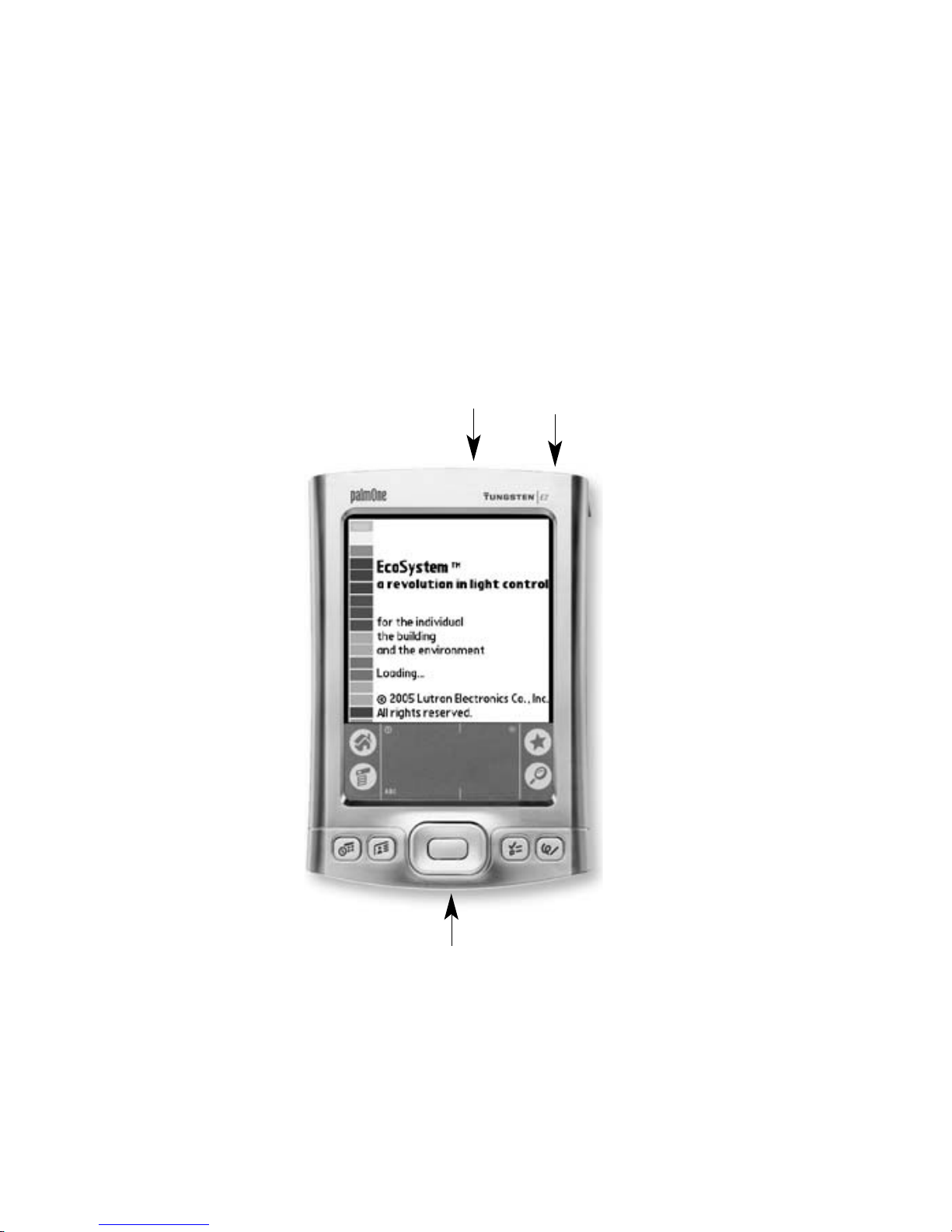
EcoSystem® Programmer
2
Power adapter
connection
Power button
(press to power on and off)
IR port
Page 8
6 EcoSystem® Programmer
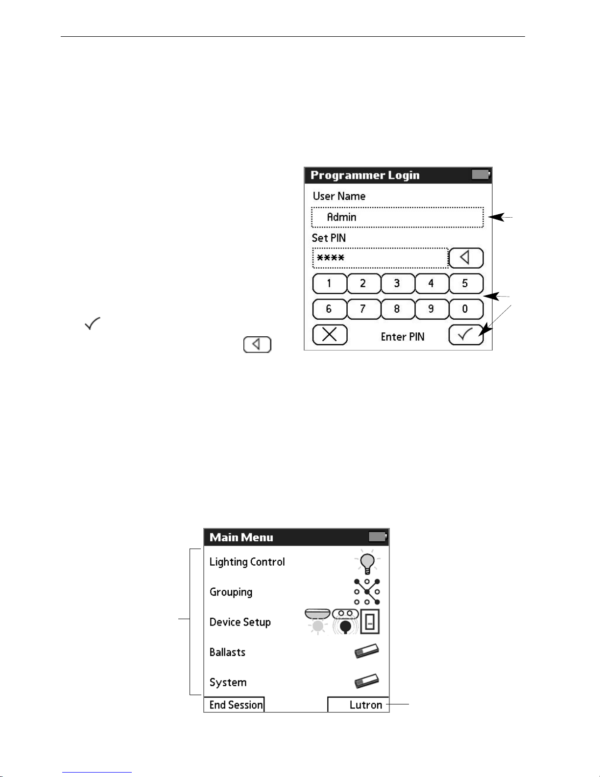
Making Screen Selections
After logging in, the Main Menu becomes the primary navigation
screen. To select a menu function, tap its title or icon with the stylus.
To make other onscreen selections, simply tap the appropriate
option.
To select a menu
function, tap its
title or icon with
the stylus.
Logging In
When the programmer is powered on, the user is prompted to enter
a user name and personal identification number (PIN). PINs must
include four to seven numbers. The default PIN is 4321.
11
Press the power button on the
top of the programmer to
power it on.
22
When the Programmer Login
screen displays, select your
User Name.
33
Tap the keypad with the stylus
to enter your PIN, then tap
.
NOTE: To backspace, tap .
33
22
Tap to display
information about
the software
Page 9
Programming Guide 7
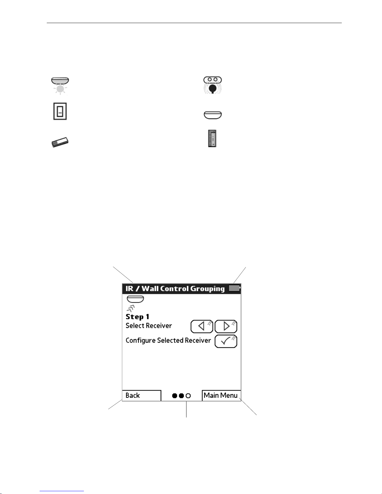
Programming Screen Components
The main components of EcoSystem programming screens are
identified below.
Dots representing major
steps in the current
function (completed
steps are colored in)
Tap to return to
the previous
screen
Battery life
Screen name
Control Device Icons
The following control device icons are used on programmer screens.
Daylight sensor Occupant sensor
Wallstation IR receiver
Ballast Contact closure
Tap to display
the Main Menu
Page 10
8 EcoSystem® Programmer
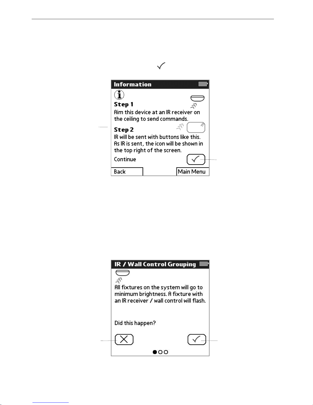
Information Screens
Information screens are displayed after menu functions are selected.
These screens are for informational purposes only. Read the
onscreen instructions and then tap to continue.
Sample
Information screen
Tap here to
continue
Prompt Screens
Prompt screens ask the user to confirm that an appropriate action
occurred during programming.
Tap here if
action happened
Tap here if action
did not happen
Page 11

Programming Guide 9
Charging the Programmer
To charge the EcoSystem programmer, plug the AC charger into an
outlet and connect it to the base of the programmer.
Logging Out
To exit the programmer software, from the Main Menu, tap
EEnndd SSeessssiioonn
and then
LLoogg OOuutt
.
Page 12

Programming
Your System
Typical Programming Workflow
Following is the typical workflow needed to program a new
EcoSystem when it is installed. This guide includes detailed
instructions for each programming step.
11 AAddddrreessss tthhee ssyysstteemm..
Begin by addressing the ballasts using the
EcoSystem programmer. This enables the programmer to
communicate with the ballasts and configure their settings.
22 CCoonnffiigguurree ffiixxttuurree ggrroouuppss..
Next, configure the group of fixtures to
be controlled by each device (IR receiver, daylight sensor, wall
control, occupant sensor, or contact closure). A group can be as
small as one fixture or as large as the entire EcoSystem bus.
33 SSeett uupp ddeevviicceess..
Once fixture groups have been configured for
each control device, set custom preferences for each device.
44 CCoonnffiigguurree bbaallllaasstt sseettttiinnggs
s..
To further fine-tune the system,
customize the high level and emergency settings for the ballasts.
55 CCoonnffiigguurree ccoonnttaacctt cclloossuurreess..
To allow EcoSystem to integrate with
third-party systems, configure contact closures on the bus supply
to specify occupancy/vacancy settings, select scenes, or
respond to peak demand.
66 PPrrooggrraamm bbaallllaassttss ttoo sseeaassoonn nneeww fflluuoorreesscceenntt llaammppss..
Program the
ballasts to operate at full intensity before dimming. New
fluorescent lamps can have impurities which can impact their
dimming performance. Follow the lamp manufacturer’s
recommendations on lamp seasoning requirements.
Refer to the following topics for detailed procedures on how to
perform each programming step.
3
Page 13

Programming Guide 11
How an EcoSystem® Bus Prioritizes Inputs
When programming a system, it is important to understand how the
ballasts prioritize inputs:
11.. EEmmeerrggeennccyy ccoommmmaanndd ((ttyyppiiccaallllyy lliigghhttss ttoo ffuullll oonn))..
The ballast’s first
priority is to ensure that no emergency exists in the building. If an
emergency exists, all emergency fixtures are automatically set to
their emergency level and all manual lighting adjustments are
ignored. If an emergency does not exist, the ballast proceeds to
the next level of priority.
22.. PPrrooggrraammmmiinngg ccoommmmaannddss..
The second priority is to respond to a
user programming the ballast. If programming commands are
being sent, the ballast responds to the commands, but ignores
any sensor or control device input. If no programming commands
are being sent, the next priority is queued.
33.. DDaayylliigghhtt sseennssoorr
iinnppuutt..
The third priority is input from daylight
sensors. The daylight sensors are checked to set the “high level,”
or the maximum light level the ballasts can be manually set to.
44.. OOccccuuppaannccyy sseennssoorr iinnppuutt oorr ppeerrssoonnaall ccoonnttrrooll tthhrroouugghh IIRR rreemmoottee oorr
wwaallll ccoonnttrrooll..
After checking the daylight sensor, the ballast waits
for the occupant sensor to detect a person in the room or for
input from a manual control. Manual control inputs come from
users dimming the lights up or down with a wall control or IR
remote. The lights will go to the level requested by the
occupancy sensor or personal control that last changed.
Page 14
12 EcoSystem® Programmer
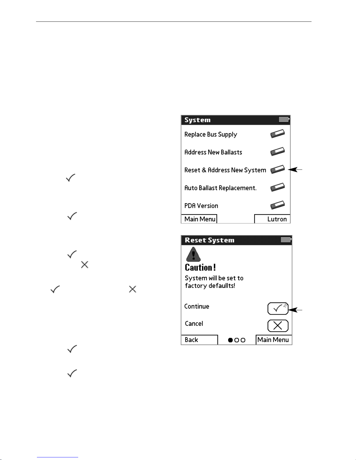
Addressing the System
Prior to programming, each ballast must be addressed. This enables
the programmer to communicate with the ballasts and program their
settings.
NOTE: To address new ballasts added to an existing system, refer to
page 60.
11
From the Main Menu, tap
SSyysstteemm..
22
Tap
RReesseett && AAddddrreessss NNeeww
SSyysstteemm
.
33
Read the instructions, then
tap to continue.
NOTE: Occupant sensors do not
have integrated IR receivers.
44
Tap to continue.
CCaauuttiioonn!!
System will be set to
factory defaults.
55
Tap to confirm the reset.
(Or tap to
CCaanncceell
.)
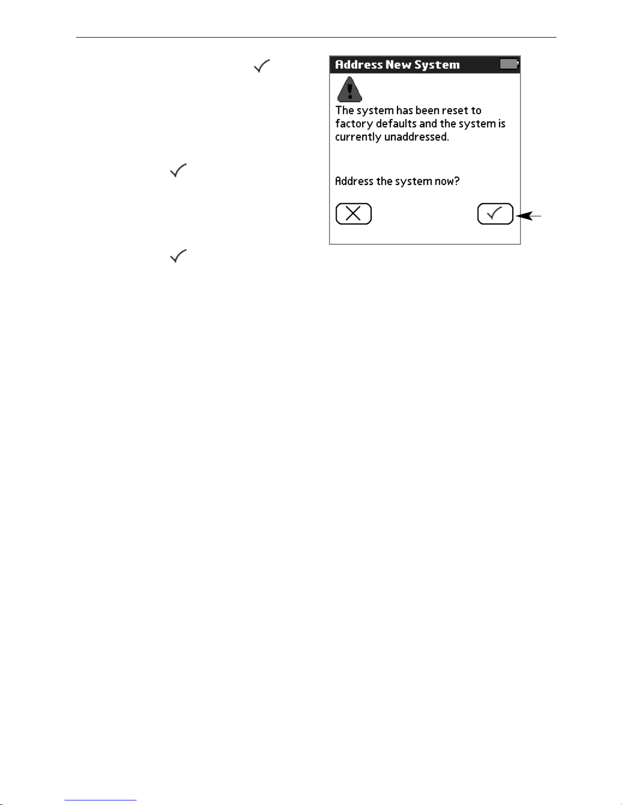
66
If all ballasts flash 3 times, tap
. Otherwise, tap .
NOTE: If fixtures do not flash, the
signal from the programmer did
not reach the IR control device.
Refer to page 4 for details.
77
Tap to address the
system.
88
Tap to begin addressing.
55
22
Page 15
Programming Guide 13
99
If all fixtures flash, tap .
Fixtures will go to minimum
brightness as they are
addressed.
1100
If all fixtures are at minimum
level, tap .
CCaauuttiioonn!!
Wait until all fixtures flash
and are at their minimum level.
1111
If all fixtures go to their high
level, tap .
77
Page 16
14 EcoSystem® Programmer
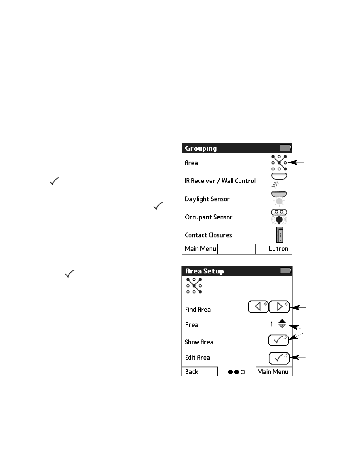
Configuring Areas
Areas allow a number of fixtures and their associated sensors to be
quickly grouped together. If fixtures are added or removed from an
area, sensors within the area are automatically assigned to control
them, overriding any preexisting grouping in the area. If multiple
daylight sensors are in the area, only one is assigned. Once
created, areas can be modified through the normal sensor grouping
means. Any area can be configured from any IR receiver. It is not
necessary to directly access a sensor within the area being created.
11
From the Main Menu, tap
GGrroouuppiinngg
and then
AArreeaa
.
22
Read the instructions, then tap
to continue.
33
Point the programmer at any
IR control device and tap
to begin communication.
44
If a single fixture flashes, then
fixtures in area 1 go to full
brightness and other fixtures
go to minimum brightness,
tap .
NOTE: If all fixtures flash three
times and then go to minimum
brightness, area 1 is empty.
55
Use the left and right arrow
buttons to scroll to the area
you want to modify. All fixtures
in the area will go to maximum
brightness and all other
fixtures will go to minimum
brightness.
Or, use the up and down
arrows and select
SShhooww AArreeaa
if you know the area number
you want to modify.
55
66
-OR-
11
55
Page 17
Programming Guide 15
66
Select
EEddiitt AArreeaa
to modify the
selected area.
77
If a single fixture flashes, then
fixtures in the selected area go
to full brightness and other
fixtures go to minimum
brightness, tap .
NOTE: If all fixtures flash three
times and then go to minimum
brightness, the selected area is
empty.
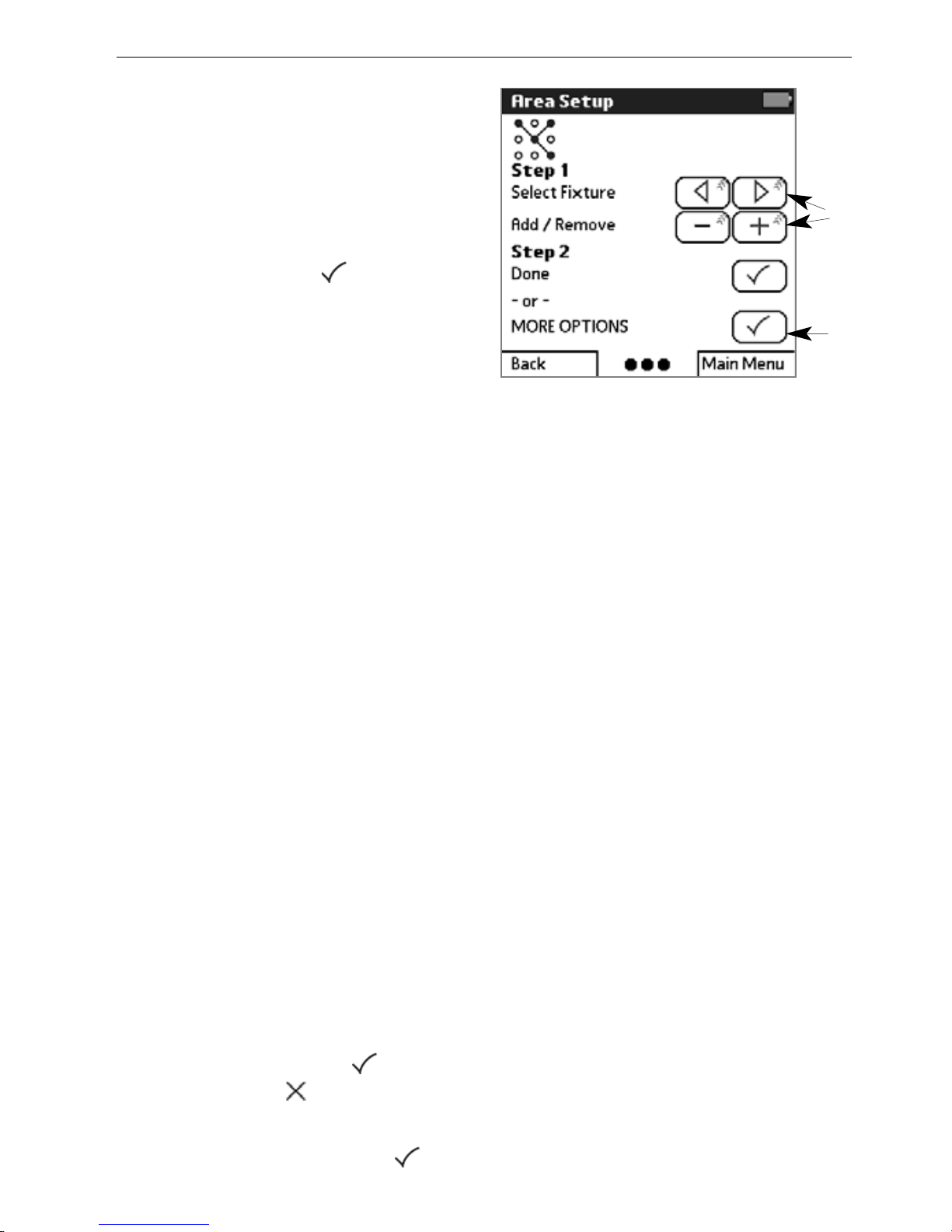
88
Scroll to the desired fixture
(selected fixture will flash). Tap
++
to add the fixture to the
area, or
——
to remove it.
Repeat for each fixture to be
added or removed from the
area.
99
To clear all the ballasts in the
area, select
MMOORREE OOPPTTIIOONNSS
,
then
RReemmoovvee AAllll BBaallllaassttss ffrroomm
GGrroouupp
.
To add all the ballasts to the
area, select
MMOORREE OOPPTTIIOONNSS
,
then
AAdddd AAllll BBaallllaassttss ttoo
GGrroouupp
.
1100
Select
DDoonnee
to finish editing
areas, or
SSeettuupp AAnnootthheerr AArreeaa
under
MMOORREE OOPPTTIIOONNSS
.
1111
Once editing is complete,
select
GGrroouupp AAllll SSeennssoorrss iinn
tt
hhiiss AArreeaa
. Acknowledge the
warning, then tap to
continue or to cancel.
1122
When done, if all fixtures go
to their high level, tap .
88
99
Page 18
16 EcoSystem® Programmer
Configuring Fixture Groups
A group of fixtures must be configured for each sensor or control.
By grouping multiple fixtures, lighting zones can be easily set up and
changed. Any of the grouping modes can be configured from any IR
receiver. It is not necessary to directly access the sensor being
grouped.
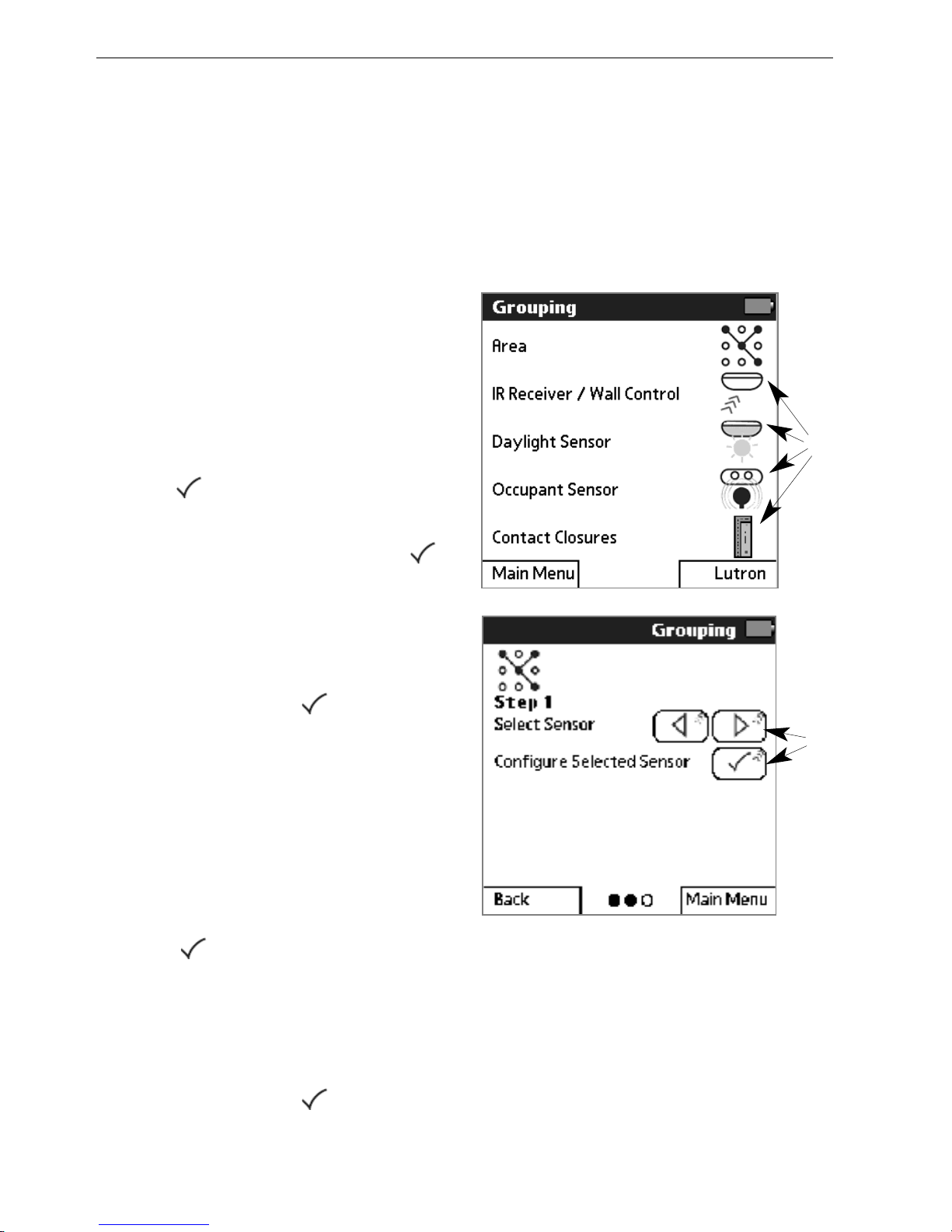
11
From the Main Menu, tap
GGrroouuppiinngg
.
22
Tap the icon for the sensor,
control, or contact closure to
be configured.
33
Read the instructions, then
tap to continue.
44
Point the programmer at any
IR control device and tap
to begin communication.
55
If a fixture connected to the
sensor flashes and other
fixtures go to minimum
brightness, tap .
NOTE: If all fixtures flash three
times and then return to normal,
no sensor was detected.
66
Use the left and right arrow
buttons to scroll to the sensor
you want to group (its
connected fixture will flash).
Tap to configure the
selected sensor.
77
If the fixtures for this sensor
go to full brightness and other
fixtures go to minimum
brightness, tap .
66
22
Page 19
Programming Guide 17
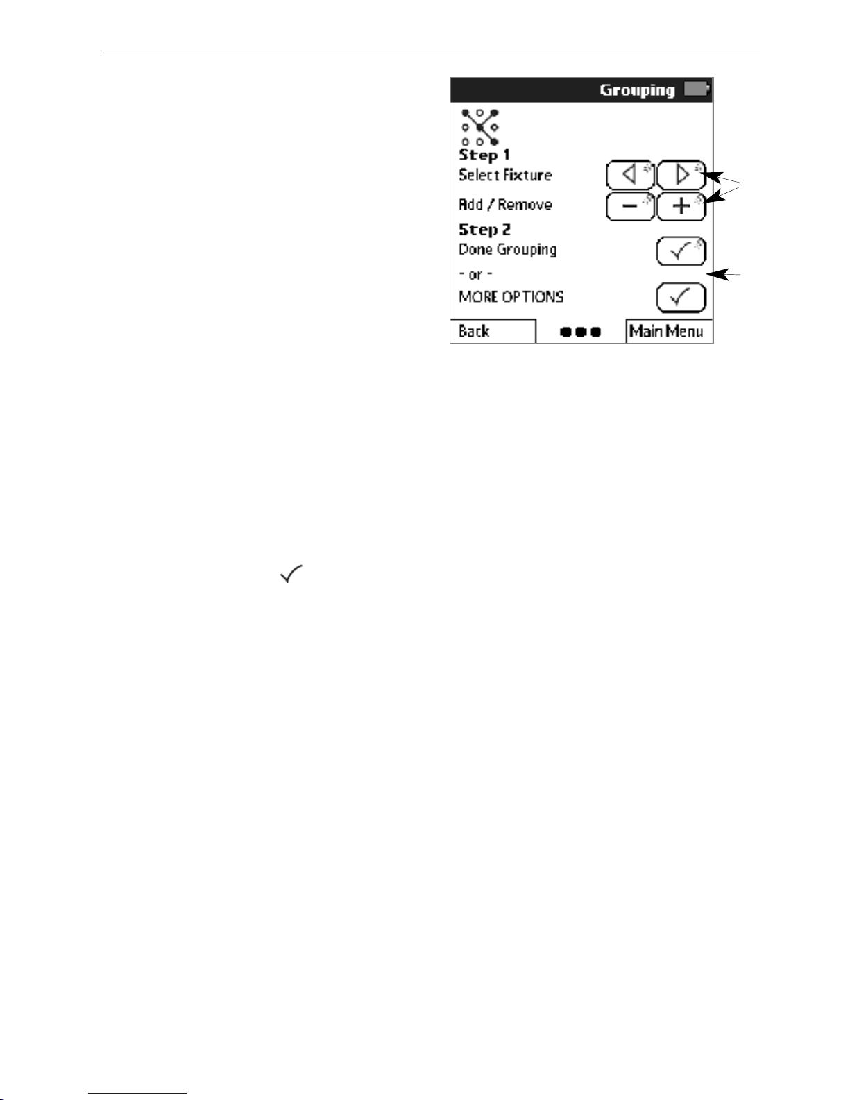
88
Scroll to the desired fixture
(selected fixture will flash). Tap
++
to add the fixture to the
group, or ––to remove it.
Repeat this step for each
fixture to be added or
removed from the group.
99
Select
DDoonnee GGrroouuppiinngg
to exit.
Or select
MMOORREE OOPPTTIIOONNSS
and then
GGrroouupp AAnnootthheerr
SSeennssoorr
to configure another
group.
NOTE: The MORE OPTIONS
menu also enables you to quickly
add or remove all ballasts or to
quickly copy a group of ballasts
from one sensor to another.
1100
When done, if all fixtures go to
high level, tap .
Repeat this procedure to
configure groups for each sensor
and control.
99
88
Page 20
18 EcoSystem® Programmer
Setting Light Levels for Daylight Sensors
To save energy, a light level can be set for each row of fixtures in a
daylight sensor group. Throughout the day, fixtures automatically
adjust their light level based on how much daylight the space is
receiving. Light levels can be set from any IR receiver. It is not
necessary to directly access the sensor being set.
NOTE: Group fixtures before setting light levels. Refer to page 16.
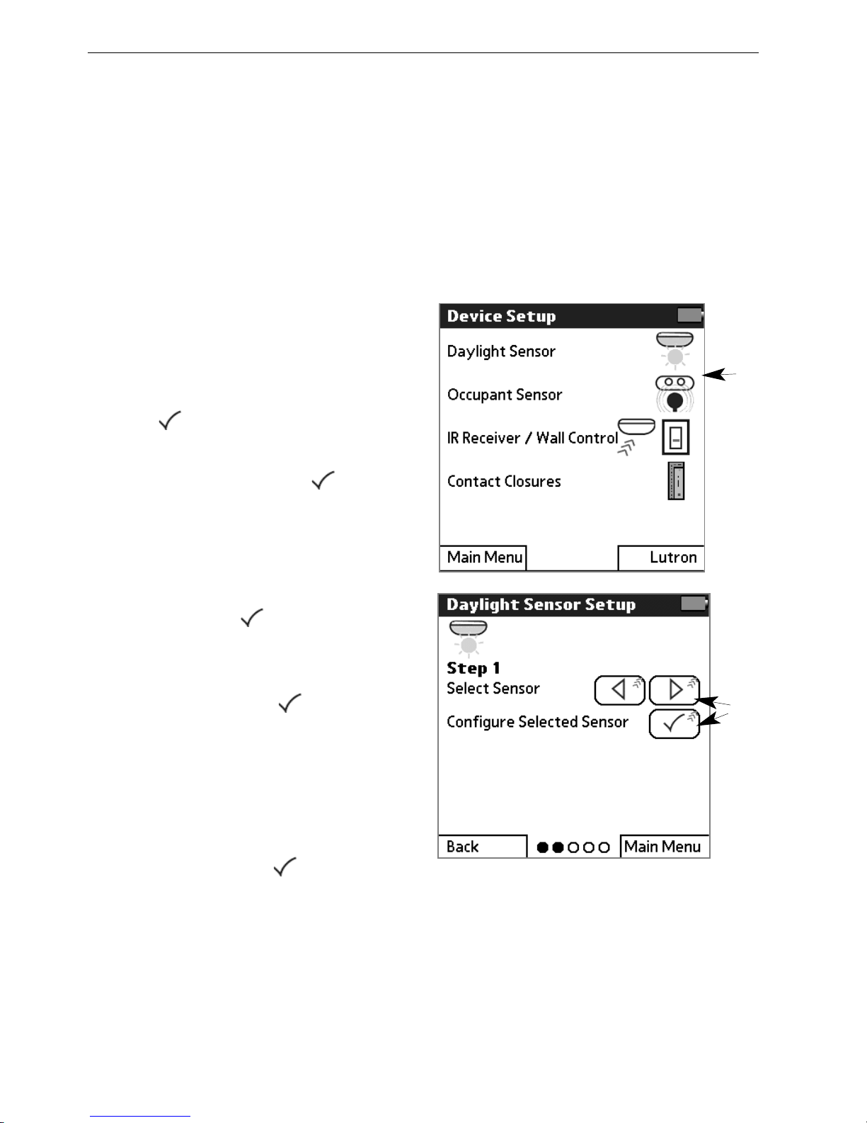
11
From the Main Menu, tap
DDeevviiccee SSeettuupp
and then
DDaayylliigghhtt SSeennssoorr
.
22
Read the instructions, then
tap to continue.
33
Point the programmer at any
IR receiver and tap to
begin communication.
44
If all fixtures go to minimum
brightness and a fixture
connected to a daylight sensor
flashes, tap .
55
Scroll to the daylight sensor to
be set (its group fixtures will
flash). Then tap to
configure the selected sensor.
66
If fixtures in row 1 of the
selected sensor group go to
full brightness and all other
fixtures go to minimum
brightness, tap .
By default, all fixtures initially
grouped to the daylight sensor
are in row 1. Up to 4 different
rows are supported in each
daylight sensor group. It is not
necessary to have fixtures in
every row.
11
55
Page 21
Programming Guide 19
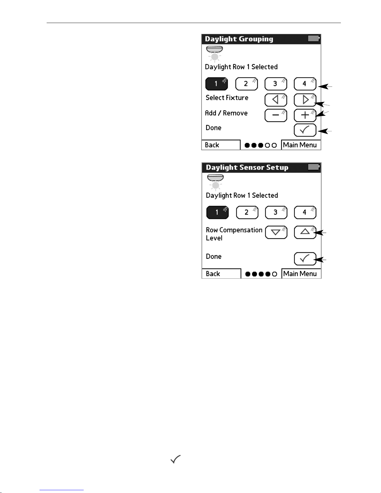
77
Select the daylight row to be
set.
88
Scroll to the desired fixture
(selected fixture will flash). Tap
++
to add the fixture to the row,
or ––to remove it. Repeat for
each fixture to be added or
removed from the row.
99
Select
DDoonnee
.
1100
Set the light level to be
maintained throughout the day
for the row. Perform this step
when a typical amount of
daylight is in the space.
Tap the down arrow button to
decrease the compensation
level. Doing this will increase
the fixture light output.
Tap the up arrow button to
increase the compensation
level, which will decrease the
fixture light output.
NOTE: Changes happen
gradually and may not be
noticeable without a light meter.
Repeat this procedure to set the
daylight light levels for each row
of fixtures in each daylight sensor
group.
1111
Select
DDoonnee
.
1122
Select
SSeettuupp AAnnootthheerr SSeennssoorr
to set up another daylight
sensor. Or select
DDoonnee
to exit.
1133
When done, if all fixtures flash
and go to high level, tap .
1100
1111
77
99
88
Page 22
20 EcoSystem® Programmer
Setting Light Levels for Occupant Sensors
Occupied and unoccupied light levels can be set for each fixture in
an occupant sensor group. The default occupied setting is the
ballast’s high level; the default unoccupied setting is OFF. Occupant
sensor levels can be configured from any IR receiver.
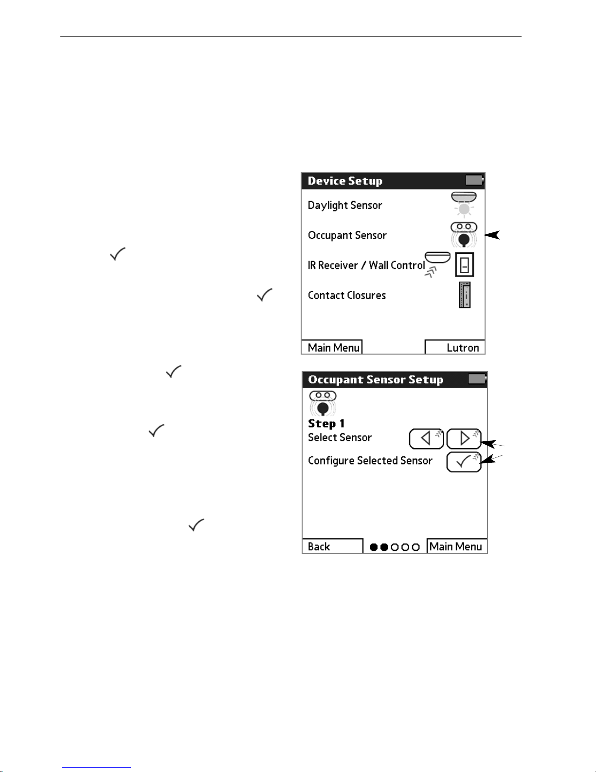
11
From the Main Menu, tap
DDeevviiccee SSeettuupp
and then
OOccccuuppaanntt SSeennssoorr
.
22
Read the instructions, then
tap to continue.
33
Point the programmer at any
IR control device and tap .
44
If all fixtures go to minimum
brightness and a fixture
connected to a sensor
flashes, tap .
55
Scroll to the sensor to be set
(its group fixtures will flash).
Then tap to configure the
selected sensor.
66
If fixtures in the sensor group
go to their occupied level and
other fixtures go to minimum
brightness, tap .
55
11
Page 23

Programming Guide 21
77
Select
SSeett OOccccuuppiieedd LLeevveell
or
SSeett UUnnooccccuuppiieedd LLeevveell
.
88
If fixtures in the group go to
their occupied/unoccupied
level, tap .
NOTE: The intensity will change
as you make your selection. If
Unaffected, the ballast’s light level
will not change when becoming
occupied/unoccupied.
99
Tap the desired occupied or
unoccupied light level. If needed,
use the arrow keys to adjust the
selected level incrementally.
1100
Select
DDoonnee
.
1111
Depending on what you want
to do next, select:
• Continue Setup of Current
Sensor
• Setup Another Sensor
• Done
1122
When done, if all fixtures flash
and go to high level, tap .
Repeat this procedure to set the
occupied and unoccupied light
levels for each occupant sensor.
77
1100
99
Page 24

22 EcoSystem® Programmer
Setting Light Levels for Contact Closures
Occupied and unoccupied light levels can be set for each fixture in
a contact closure group. The default occupied setting is the ballast’s
high level; the default unoccupied setting is OFF. Contact closure
levels can be configured from any IR receiver. These settings apply
only if the contact closures are set to Normal Mode. Refer to
page 42 for information on contact closure modes.
11
From the Main Menu, tap
DDeevviiccee SSeettuupp
and then
CCoonnttaacctt CClloossuurreess
.
22
Read the instructions. Point
the programmer at any IR
control device, then tap to
continue.
33
Select
CCoonnttaacctt CClloossuurree SSeettuupp
.
44
Select
CCoonnttaacctt CClloossuurree 11
or
CCoonnttaacctt CCl
loossuurree 22
.
55
If a group of fixtures goes to
full brightness and other
fixtures go to minimum
brightness, tap .
66
Select
SSeett OOccccuuppiieedd LLeevveell
or
SSeett UUnnooccccuuppiieedd LLeevveell
.
77
If fixtures in the group go to
their occupied/unoccupied
level, tap .
88
Tap the occupied or
unoccupied light level. If
needed, use the arrow keys to
adjust the selected level
incrementally.
33
11
Page 25

Programming Guide 23
66
99
Select Done.
1100
Depending on what you want
to do next, select:
• Continue Setup of Current
Sensor
• Setup Another Sensor
• Done
1111
When done, if all fixtures go to
high level, tap .
Repeat this procedure to set the
occupied and unoccupied light
levels for each contact closure
group.
88
99
Page 26

Setting an Additional Timeout Period for Occupant
Sensors
Occupant sensors can be set up to turn fixtures off automatically
after a period of inactivity. The default timeout is zero seconds. Any
timeout programmed into the ballast will be in addition to that of the
occupant sensor. Consult the installation guide for your occupant
sensor to determine the total delay.
11
From the Main Menu, tap
DDeevviiccee SSeettuupp
and then
OOccccuuppaanntt SSeennssoorr
.
22
Read the instructions, then
tap to continue.
33
Point the programmer at any
IR control device and tap
to begin communication.
44
If a group of fixtures goes to
full brightness and other
fixtures go to minimum
brightness, tap .
55
Scroll to the sensor to be set
(its group of fixtures will flash).
Then tap to configure the
selected sensor.
66
If all fixtures go to minimum
brightness and a fixture
connected to an occupant
sensor flashes, tap .
77
Select
SSeett TTiimmeeoouutt
.
88
Note the warning, then tap
to continue.
66
77
24 EcoSystem® Programmer
Page 27

Programming Guide 25
99
Select the number of minutes
of inactivity after which the
fixture group will turn off.
1100
Select Done.
1111
Depending on what you want
to do next, select:
• Continue Setup of Current
Sensor
• Setup Another Sensor
• Done
1122
When done, if all fixtures flash
and then go to high level, tap
.
Repeat this procedure to set a
timeout for each additional
occupant sensor.
99
1100
Page 28
26 EcoSystem® Programmer
Setting Up Scenes for Wall Controls
Wall controls can be set up to activate scenes (preset light levels). A
different scene can be configured for each button on the control.
Note that all wall controls in a given group will operate the same.
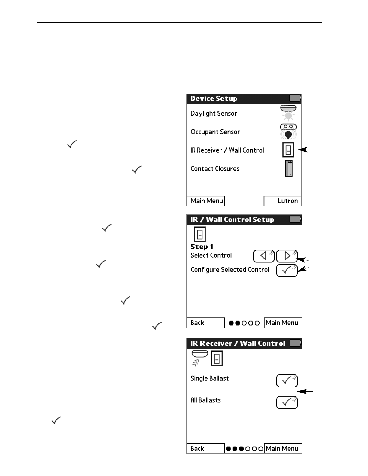
11
From the Main Menu, tap
DDeevviiccee SSeettuupp
and then
IIRR RReecceeiivveerr//WWaallll CCoonnttrrooll
.
22
Read the instructions, then
tap to continue.
33
Point the programmer at any
IR receiver and tap to
begin communication.
44
If all fixtures go to minimum
brightness and a fixture
connected to a wall control
flashes, tap .
55
Scroll to the wall control to be
set (its group of fixtures will
flash). Tap to configure the
selected control.
66
Select
SSiinnggllee BBaallllaasstt
or
AAllll
BBaallllaassttss
and tap .
77
If the ballasts flash and then
go to a scene level, tap .
88
Select the number of the
scene to be set (scene 1
matches the first button on the
control, scene 2 matches the
second button, and so on).
99
If fixtures for this control go to
their selected scene level, tap
.
11
55
66
Page 29

Programming Guide 27
1100
If modifying a single fixture,
scroll to the desired fixture
(selected fixture will flash).
Adjust the scene level up or
down, then select
SSeenndd LLeevveell
to transmit the level to the
fixture.
Or, select
UUnnAA
if the fixture
should be unaffected for that
scene.
Repeat for each scene on the
control.
Select
DDoonnee
.
1111
Select
SSeettuupp AAnnootthheerr CCoonnttrrooll
to set scenes for another wall
control. Or select
DDoonnee
to exit.
1122
When done, if all fixtures go to
high level, tap .
Repeat this procedure to set the
scene levels for each IR receiver
and wall control.
88
1100
Page 30

28 EcoSystem® Programmer
Configuring Ballasts
The factory default settings for ballasts are: high level = 100% and
emergency setting = 100%. Each of these settings can be
customized to meet specific lighting needs.
11
From the Main Menu, tap
BBaallllaassttss
and then
CCoonnffiigguurree
BBaallllaasstt
.
22
Read the instructions, then
tap to continue.
33
Point the programmer at any
IR control device, then tap
to begin communication.
44
If the fixture connected to the
control device flashes and
other fixtures go to minimum
brightness, tap .
55
Scroll to a specific ballast (its
fixture will flash). Tap to
select it.
- OR -
To configure all the ballasts,
select
CCoonnffiigguurree AAllll BBaallllaassttss
.
66
If selected ballasts go to full
brightness and other fixtures
go to minimum brightness, tap
.
Refer to the following topics to:
• Set high end trim
• Set the emergency level
• Season lamps
• Perform additional ballast
configuration options
55
-OR-
11
Page 31

Programming Guide 29
Setting a Ballast’s High End Trim
A ballast’s high end trim setting controls the maximum light level for a
dimming fixture. The factory default high level = 100%. This setting
can be customized to meet specific lighting needs.
11
From the
CCoonnffiigguurree MMeennuu
, tap
SSeett HHiigghh EEnndd TTrriimm
.
NOTE: For procedures on how to
to select one or all ballasts and
then display the Configure menu,
refer to page 28.
22
Tap to begin setup.
33
If selected ballasts flash and
go to their high level, tap .
44
Use the arrow keys to adjust
the level incrementally.
55
Select
SSeenndd
to transmit the
level to the fixture.
66
If the ballast(s) flash once, tap
.
77
Depending on what you want
to do next, select:
• Continue Configuration of
Current Ballast(s)
• Configure Different
Ballast(s)
• Done
88
When done, if the last
configured ballast(s) flash and
go to their high level, tap .
11
44
55
Page 32

30 EcoSystem® Programmer
Setting a Ballast’s Emergency Level
The emergency setting controls a ballast’s light level in case of an
emergency (for example, a power outage or fire). The default
emergency setting is the ballast’s high level.
11
From the
CCoonnffiigguurree MMeennuu
, tap
SSeett EEmmeerrggeennccyy LLeevveell
.
NOTE: For procedures on how to
select one or all ballasts and then
display the Configure menu, refer
to page 28.
22
Tap to begin setup.
33
If selected ballasts flash and
go to their emergency level,
tap .
44
Tap an emergency light level,
then tap .
NOTE: The intensity will change
as you make your selection. If
Unaffected, the ballast’s light level
will not change in an emergency.
55
Depending on what you want
to do next, select:
• Continue Configuration of
Current Ballast(s)
• Configure Different
Ballast(s)
• Done
66
When done, if the last
configured ballast(s) flash and
go to their high level, tap .
11
44
Page 33

Programming Guide 31
Seasoning New Fluorescent Lamps
New fluorescent lamps can have impurities in them that lamp
manufacturers cannot eliminate completely. Contact your lamp
manufacturer for their lamp seasoning recommendations.
EcoSystem provides a convenient means for seasoning lamps for
100 hours. When a system is first installed, program ballasts to
season all new lamps if needed. As lamps are added or replaced,
program the seasoning process only for those ballasts.
11
22
11
From the
CCoonnffiigguurree MMeennuu
, tap
LLaammpp SSeeaassoonniinngg
.
NOTE: For procedures on how to
to select one or all ballasts and
then display the Configure menu,
refer to page 28.
22
Select
SSttaarrtt LLaammpp SSeeaassoonniinngg
to force the light to full
intensity for 100 hours.
Otherwise, select
CCaanncceell
LLaammpp SSeeaassoonniinngg
.
NOTE: To temporarily pause the
seasoning process, select
PPaauussee
L
Laammpp SSeeaassoonniinngg
.
33
If selected ballast(s) flash and
go to their high level, tap .
44
Depending on what you want
to do next, select:
• Continue Configuration of
Current Ballast(s)
• Configure Different
Ballast(s)
• Done
55
When done, if the last
configured ballast(s) flash and
go to their high level, tap .
Page 34

32 EcoSystem® Programmer
Configuring BMJ / XPJ Settings
The EcoSystem BMJ power module allows dimming and switching
of up to 16A of 3-wire fluorescent ballasts. The XPJ power module
allows switching of up to 16A of non-dim loads. The operation of
these devices can be configured from the BMJ / XPJ Settings
menu. These settings can also be used on a BMF ballast module
fixture mount which can dim up to 2A of 3-wire fluorescent ballasts
and is intended for mounting within the fixture.
11
From the
CCoonnffiigguurree MMeennuu
, tap
MMOORREE OOPPTTIIOONNSS
.
NOTE: For procedures on how to
to select one or all ballasts and
then display the Configure menu,
refer to page 28.
22
Select
BBMMJJ // XXPPJJ SSeettttiinnggss
.
The BMJ / XPJ Settings menu
displays and your can:
• Set the XPJ on and off level
• Set the Gain
• Set the XPJ or BMJ Mode
Refer to the following topics for
detailed procedures on how to
perform each of these
programming steps.
22
Page 35

Programming Guide 33
Setting the XPJ On and Off Level
You can set the light level at which the XPJ power module turns on
or off its output when doing daylighting or being controlled by a
scene.
11
From the BMJ / XPJ Settings
menu, select
XXPPJJ OOnn LLeevveell
or
XXPPJJ OOffff LLeevveell
.
NOTE: For procedures on how to
display the BMJ / XPJ Settings
menu, refer to page 32.
22
If selected ballasts flash and
go to their high level, tap .
33
Tap a level, then tap .
44
Depending on what you want
to do next, select:
• Continue Configuration of
Current Ballast(s)
• Configure Different
Ballast(s)
• Done
55
When done, if the last
configured ballast(s) flash and
go to their high level, tap .
11
33
Page 36

34 EcoSystem® Programmer
Setting the Gain
You can directly set the BMJ or XPJ module’s sensitivity to changing
light levels detected by the daylight sensor.
11
From the BMJ / XPJ Settings
menu, select
GGaaiinn
.
NOTE: For procedures on how to
display the BMJ / XPJ Settings
menu, refer to page 32.
22
If selected ballasts flash and
go to their high level, tap .
33
Select a gain level of 1
through 10, with 1 meaning
the module will be least
sensitive to light level changes
and 10 being the most
sensitive. Then tap .
44
Depending on what you want
to do next, select:
• Continue Configuration of
Current Ballast(s)
• Configure Different
Ballast(s)
• Done
55
When done, if the last
configured ballast(s) flash and
go to their high level, tap .
11
33
Page 37

Programming Guide 35
Setting XPJ or BMJ Mode
You can force the module to act as either an XPJ (where the relay
turns on and off at particular light levels) or a BMJ (where the relay
remains on at all levels except for off).
11
From the BMJ / XPJ Settings
menu, select
XXPPJJ // BBMMJJ
MMooddee
.
NOTE: For procedures on how to
display the BMJ / XPJ Settings
menu, refer to page 32.
22
If selected ballasts flash and
go to their high level, tap .
33
Select
XXPPJJ
or
BBMMJJ
.
44
Depending on what you want
to do next, select:
• Continue Configuration of
Current Ballast(s)
• Configure Different
Ballast(s)
• Done
55
When done, if the last
configured ballast(s) flash and
go to their high level, tap .
11
33
Page 38

36 EcoSystem® Programmer
Limiting Restrikes
When there is a problem with the lamp, wiring, or ballast, the ballast
may continue to attempt to strike the lamp. Since this may be
undesirable, you can limit the number of restrikes to three times. If
the lamp still does not light, the ballast will not retry until instructed
to turn the lights off and back on again by a sensor or other system
input.
11
From the Configure Menu, tap
MMOORREE OOPPTTIIOONNSS
then
LLiimmiitt
RReessttrriikkeess
.
NOTE: For procedures on how to
select one or all ballasts and then
display the Configure menu, refer
to page 28.
22
Tap to begin setup.
33
If selected ballasts flash and
go to their high level, tap .
44
Select
EEnnaabbllee
to limit ballast
restrike attempts, or
DDiissaabbllee
to
restore the default operation of
unlimited restrike attempts.
55
Depending on what you want
to do next, select:
• Continue Configuration of
Current Ballast(s)
• Configure Different
Ballast(s)
• Done
66
When done, if the last
configured ballast(s) flash and
go to their high level, tap .
44
11
Page 39

Programming Guide 37
Setting Occupied and Unoccupied Levels
The occupied and unoccupied settings determine the level the lights
will go to when they are in the occupied or unoccupied state. By
default, the occupied level is high end and the unoccupied level is
OFF. These settings are the same as those set during the
programming of occupant sensors.
11
From the Configure Menu, tap
MMOORREE OOPPTTIIOONNSS
and then
SSeett OOccccuuppiieedd LLeevveell
or
SSeett
UUnnooccccuuppiieedd LLeevveell
.
NOTE: For procedures on how to
select one or all ballasts and then
display the Configure menu, refer
to page 28.
22
Tap to begin setup.
33
If selected ballasts flash and
go to their high level, tap .
44
Tap an occupied or
unoccupied light level. If
needed, use the arrow keys
to adjust the selected level
incrementally.
NOTE: The intensity changes as
you make your selection. If
Unaffected, the ballast’s light level
will not change when becoming
occupied/unoccupied.
55
Select
DDoonnee
.
66
Select
DDoonnee..
Or, select
another option to continue
configuring ballasts.
7
7
When done, if the last
configured ballast(s) flash and
go to their high level, tap .
11
44
55
Page 40

38 EcoSystem® Programmer
Setting Egress Levels
The egress level specifies the minimum light level for a ballast.
Under no conditions can the ballast dim beneath the egress level. If
the egress level is above its default value of OFF, the lights will not
turn off.
11
From the Configure Menu, tap
MMOORREE OOPPTTIIOONNSS
twice and
then
EEggrreessss LLeevveell
.
NOTE: For procedures on how to
select one or all ballasts and then
display the Configure menu, refer
to page 28.
22
Tap to begin setup.
33
If selected ballasts flash and
go to their high level, tap .
44
Tap an egress level. If needed,
use the arrow keys to adjust
the selected level
incrementally.
NOTE: The intensity changes as
you make your selection. If
Disable is selected, the lights will
be able to turn off normally.
55
Select
DDoonnee
.
66
Select
DDoonnee..
Or, select
another option to continue
configuring ballasts.
77
When done, if the last
configured ballast(s) flash and
go to their high level, tap .
11
55
44
Page 41
Programming Guide 39
Setting Daylight Low End
The daylight low end is the lowest level a daylight sensor is allowed
to dim the lights. It can be set from 0% (allowing the photo sensor to
turn the lights off) to 100% (preventing the photo sensor from
working at all).
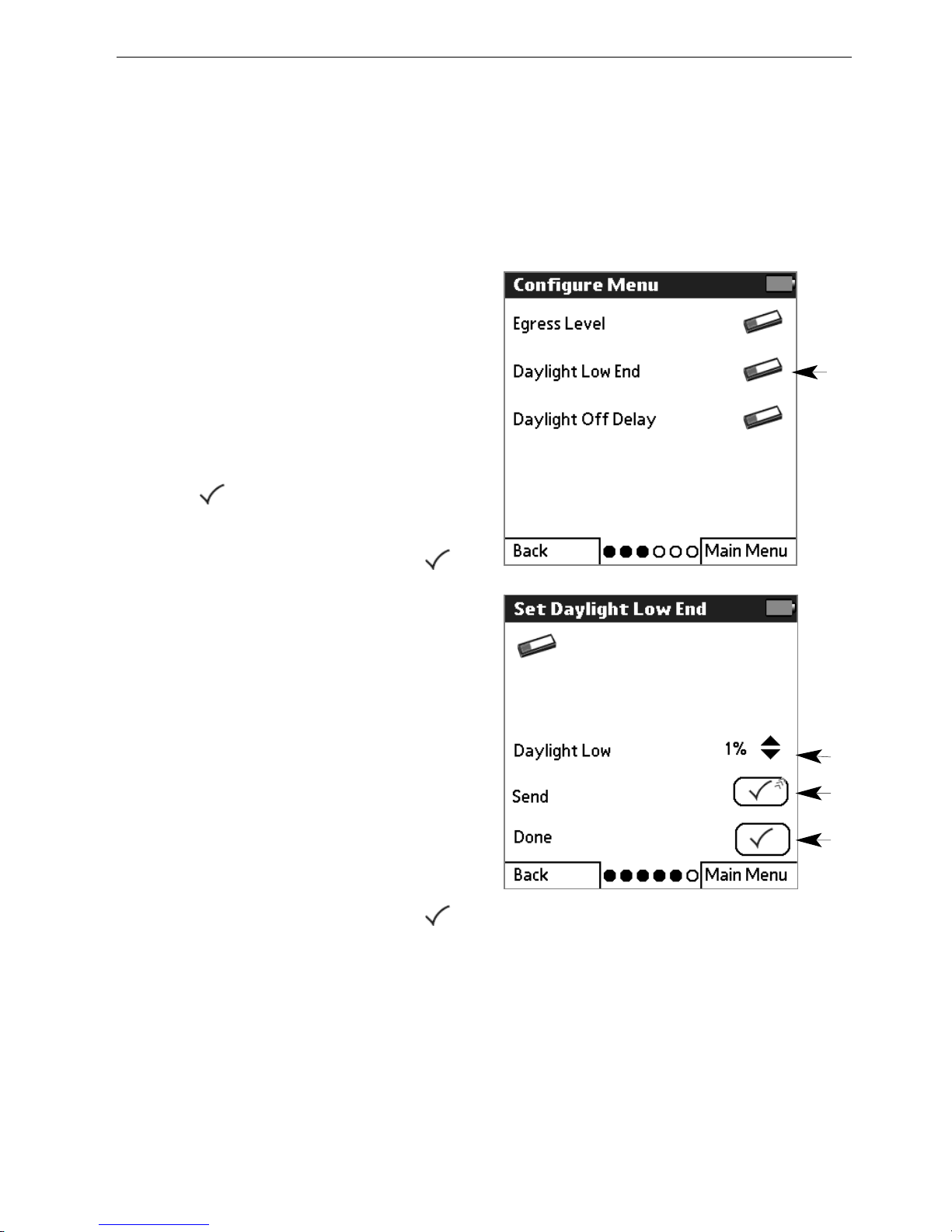
11
From the Configure Menu, tap
MMOORREE OOPPTTIIOONNSS
twice and
then
DDaayylliigghhtt LLooww EEnndd
.
NOTE: For procedures on how to
select one or all ballasts and then
display the Configure menu, refer
to page 28.
22
Tap to begin setup.
33
If selected ballasts flash and
go to their high level, tap .
44
Use the arrow keys to adjust
the level incrementally.
55
Select
SSeenndd
to transmit the
light level to the ballast.
66
Select
DDoonnee
.
77
Select
DDoonnee..
Or, select
another option to continue
configuring ballasts.
88
When done, if the last
configured ballast(s) flash and
go to their high level, tap .
11
44
55
66
Page 42

40 EcoSystem® Programmer
Setting Daylight Off Delay
The daylight off delay is the amount of time a daylight sensor needs
to detect a sufficiently low light level before it turns the lights off. This
value can be adjusted from 0 to 42 minutes, and is used only if the
daylight low end value is set to zero. Note that the daylight off delay
does not affect how quickly the lights turn back on if the sensor
detects insufficient light.
11
From the Configure Menu, tap
MMOORREE OOPPTTIIOONNSS
twice and
then
DDaayylliigghhtt OOffff DDeellaayy
.
NOTE: For procedures on how to
select one or all ballasts and then
display the Configure menu, refer
to page 28.
22
Tap to begin setup.
33
If selected ballasts flash and
go to their high level, tap .
44
Use the arrow keys to adjust
the amount of time the sensor
has to detect a sufficiently low
light level before turning off the
lights.
55
Select
SSeenndd
to transmit the
light level to the ballast.
66
When done setting the
daylight low end, select
DDoonnee
.
77
Select
DDoonnee..
Or, select
another option to continue
configuring ballasts.
88
When done, if the last
configured ballast(s) flash and
go to their high level, tap .
11
44
55
66
Page 43

Programming Guide 41
Configuring Contact Closures
Contact closure inputs on the bus supply allow integration with
external devices through their contact closure outputs. Contact
closures can be configured to select a link-wide
occupied/unoccupied status, select a scene for all devices on the
link, or enable a load shed (demand response) feature. For
information on available modes, see Lutron Application Note #236.
To assign ballasts to Normal Mode and Demand Response Mode
groups, refer to “Configuring Fixture Groups” on page 16.
11
From the Main Menu, tap
DDeevviiccee SSeettuupp
and then
CCoonnttaacctt CClloossuurreess
.
22
Read the instructions. Point
the programmer at any IR
control device, then tap to
continue.
The Contact Closure Setup menu
displays and your can:
• Set the contact closure mode
• Configure the contact closure
settings
Refer to the following topics for
detailed procedures on how to
perform these programming
steps.
11
Page 44
42 EcoSystem® Programmer
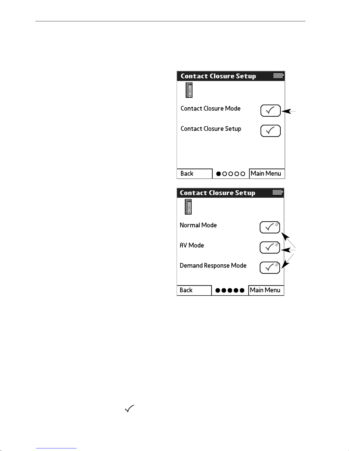
Setting the Contact Closure Mode
The contact closure mode controls how contact closures respond.
11
From the Contact Closure
Setup menu, tap
CCoonnttaacctt
CClloossuurree MMooddee
.
NOTE: For procedures on how to
display the Contact Closure
Setup menu, refer to page 41.
22
Select how the contact
closures are to respond:
•
NNoorrmmaall MMooddee
. Contact
closures apply occupied or
unoccupied mode to the
entire link.
•
AAVV MMooddee
. Contact closures
select a scene for all
ballasts on the link. Fixtures
do not need to be
assigned to the contact
closure group, as all
fixtures will respond to AV
Mode.
•
DDeemmaanndd RReessppoonnssee MMooddee
.
A contact closure reduces
the light level of all ballasts
on the link.
NOTE: The contact closure mode
applies to all contacts on the link.
The mode cannot be set on each
contact closure separately.
33
If all ballasts flash and go to
their high level, tap .
11
22
Page 45

Programming Guide 43
Setting the Demand Response Level
The demand response setting specifies the amount of reduction
applied to grouped fixtures when a contact closure is present.
11
From the Contact Closure
Setup menu, tap
CCoonnttaacctt
CClloossuurree CClloossuurree SSeettuupp
.
NOTE: For procedures on how to
display the Contact Closure
Setup menu, refer to page 41.
22
Select
CCoonnttaacctt CClloossuurree 11
or
CCoonnttaacctt CClloossuurree 22
.
33
If a group of ballasts goes to
full brightness and other
ballasts go to minimum
brightness, tap .
44
Select
SSeett DDeemmaanndd RRe
esspp..
55
If ballasts go to their occupied
level, tap .
66
Use the arrows to select the
demand response level. A
value of 100% means the
lights will stay off.
77
Select
SSeenndd
to transmit the
demand response level to the
ballasts.
88
Select
DDoonnee
when complete.
99
Select
DDoonnee..
Or, select
another option to continue
configuring ballasts.
1100
When done, if the last
configured ballast(s) flash and
go to their high level, tap .
11
44
66
77
88
Page 46

44 EcoSystem® Programmer
Setting the Contact Closure Occupied or Unoccupied
Level
This setting specifies the lighting level to be used when the space
becomes occupied or unoccupied.
11
From the Contact Closure
Setup menu, tap
CCoonnttaacctt
CClloossuurree CClloossuurree SSeettuupp
.
NOTE: For procedures on how to
display the Contact Closure
Setup menu, refer to page 41.
22
Select
CCoonnttaacctt CClloossuurree 11
or
CCoonnttaacctt CClloossuurree 22
.
33
If a group of ballasts goes to
full brightness and other
ballasts go to minimum
brightness, tap .
44
Select
SSeett OOccccuuppiieedd
LLeevveell
or
SSeett UUnnooccccuuppiieedd LLeevveell..
If
ballasts go to their occupied
or unoccupied level, tap .
66
Tap the desired light level. If
needed, use the arrow keys to
adjust the selected level
incrementally. Select
UUnnaaffffeecctteedd
if the ballasts
should not change light levels
when becoming occupied or
unoccupied.
77
Select
DDoonnee
.
88
Select
DDoonnee..
Or, select
another option to continue
configuring ballasts.
99
When done, if the last
configured ballast(s) flash and
go to their high level, tap .
11
44
66
77
Page 47

Programming Guide 45
Setting the Contact Closure Occupancy Timeout
The occupancy timeout setting specifies the number of minutes
before a fixture group turns off after contact closure input.
11
From the Contact Closure
Setup menu, tap
CCoonnttaacctt
CClloossuurree CClloossuurree SSeettuupp
.
NOTE: For procedures on how to
display the Contact Closure
Setup menu, refer to page 41.
22
Select
CCoonnttaacctt CClloossuurree 11
or
CCoonnttaacctt CClloossuurree 22
.
33
If a group of ballasts goes to
full brightness and other
ballasts go to minimum
brightness, tap .
44
Select
SSeett TTiimmeeoouutt..
5
5
If ballasts go to their occupied
level, tap .
66
Select the number of minutes
until the fixture group turns off
after contact closure input.
77
Select
DDoonnee
.
88
Select
DDoonnee..
Or, select
another option to continue
configuring ballasts.
99
When done, if the last
configured ballast(s) flash and
go to their high level, tap .
11
44
66
77
Page 48

Stand-Alone
Programming
In some applications, EcoSystem ballasts and modules are not
connected via an EcoSystem link. Ballasts can still be used in this
configuration, but sensor and control input cannot be shared
between them. Special settings are provided for ballasts and
modules used in a stand-alone configuration.
To configure a ballast in stand-alone operation, a sensor or control
capable of receiving IR commands must be connected to the ballast
and used during programming.
4
Page 49

Programming Guide 47
Accessing the Stand-Alone Programming Menu
The stand-alone programming menu enables you to configure
special settings for ballasts and modules used in a stand-alone
configuration.
11
From the Main Menu, tap
BBaallllaassttss
then
SSttaanndd--AAlloonnee
PPrrooggrraammmmiinngg
. Acknowledge
the note regarding stand-alone
programming, and tap to
continue.
22
Read the instructions. Point
the programmer at an IR
control device connected to
the ballast to be configured,
then tap to continue.
33
Point the programmer at the IR
control device and tap to
begin communication.
The Stand-Alone Programming
menu displays and you can:
• Set the emergency level
• Set the high end trim
• Perform stand-alone lamp
seasoning
• Set up a daylight or
occupancy sensor, or
configure XPJ settings
• Enable or disable 3 wire
input
• Reset the selected ballast
Refer to the following topics for
detailed stand-alone
programming procedures.
11
Page 50
48 EcoSystem® Programmer
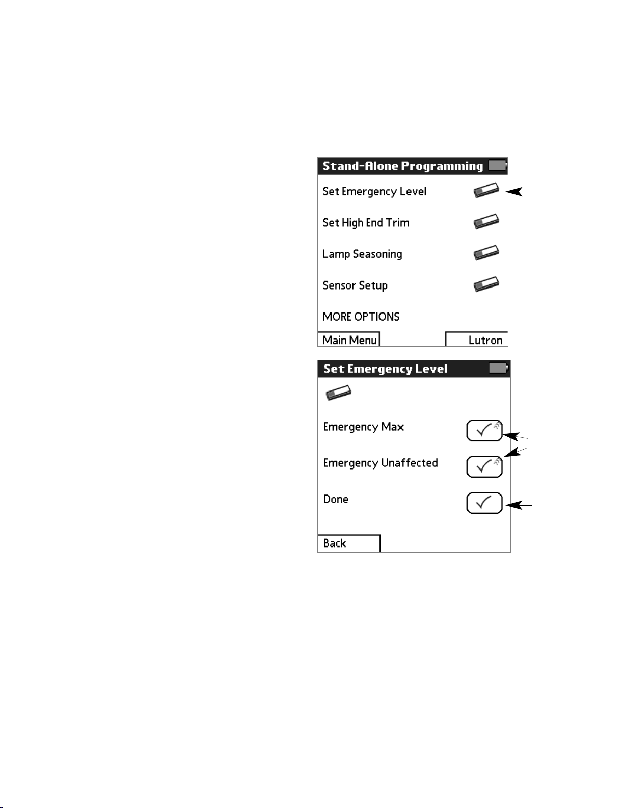
Setting Stand-Alone Emergency Level
The emergency level controls whether the ballast goes to high end
when no input is seen on the EcoSystem bus. For more information,
refer to page 30.
11
From the Stand-Alone
Programming menu, select
SSeett EEmmeerrggeennccyy LLeevveell
.
NOTE: For procedures on how to
access the Stand-Alone
Programming menu, refer to
page 47.
22
To have the lights go to their
maximum light level when no
input is detected on the digital
link, select
EEmmeerrggeennccyy MMaaxx
(default operation).
Or, to ignore a missing input
on the EcoSystem link, select
EEmmeerrggeennccyy UUnnaaffffeecctteedd
(required operation for standalone mode).
33
Select
DDoonnee
.
44
To continue configuring
settings on the current ballast,
select
CCoonnttiinnuuee SSeetttti
inngg UUpp
BBaallllaasstt
. Otherwise, select
DDoonnee
to return to the Main
menu.
22
11
33
Page 51

Programming Guide 49
11
From the Stand-Alone
Programming menu, select
SSeett HHiigghh EEnndd TTrriimm
.
NOTE: For procedures on how to
access the Stand-Alone
Programming menu, refer to
page 47.
22
Use the up and down arrows
to adjust the maximum light
level for the ballast.
33
Select
DDoonnee
.
44
To continue configuring
settings on the current ballast,
select
CCoonnttiinnuuee SSeettttiinngg UUpp
BBaallllaasstt
. Otherwise, select
DDoonnee
to return to the Main
menu.
22
Setting Stand-Alone High End Trim
The high end trim controls the maximum light level for the lamps. For
more infomration, refer to page 29.
11
33
Page 52

50 EcoSystem® Programmer
11
From the Stand-Alone
Programming menu, select
LLaammpp SSeeaassoonniinngg
.
NOTE: For procedures on how to
access the Stand-Alone
Programming menu, refer to
page 47.
22
Select
SSttaarrtt LLaammpp SSeeaassoonniinngg
to force the lights to full for
100 hours.
To adjust the programming
before the lamp seasoning is
complete, press ––to pause
the lamp seasoning timer and
return the lights to normal.
When ready, press ++to return
the lights to full and resume
the lamp seasoning timer.
33
Select
DDoonnee
.
44
To continue configuring
settings on the current ballast,
select
CCoonnttiinnuuee SSeettttiinngg UUpp
BBaallllaasstt
. Otherwise, select
DDoonnee
to return to the Main
menu.
22
Stand-Alone Lamp Seasoning
Contact your lamp manufacturer for their lamp seasoning
recommendations. For more information, refer to page 31.
11
33
Page 53

Programming Guide 51
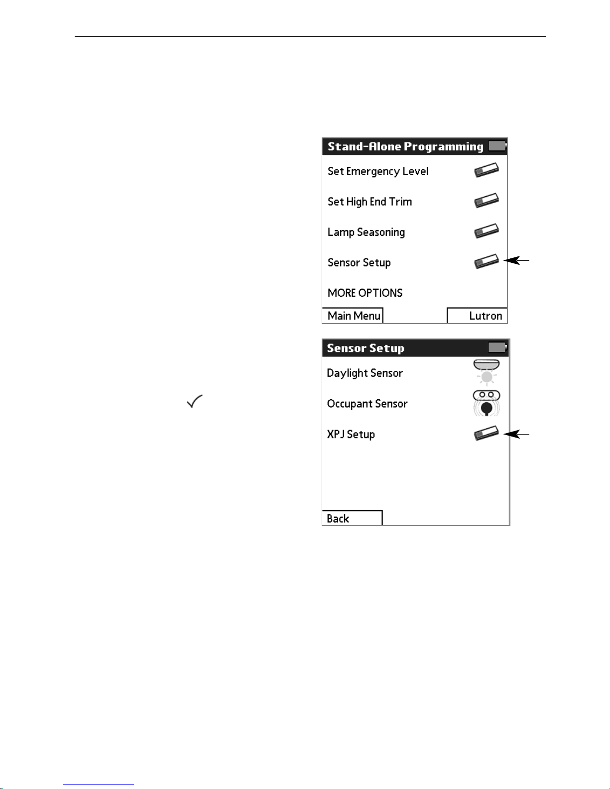
11
From the Stand-Alone
Programming menu, select
SSeennssoorr SSeettuupp
.
NOTE: For procedures on how to
access the Stand-Alone
Programming menu, refer to
page 47.
22
Select
DDaayylliigghhtt SSeennssoorr
.
33
When the sensor detects a
significant amount of daylight,
use the up and down
TTaarrggeett
LLeevveell
arrows to adjust the
current light level until it
matches the desired amount.
It may take up to 30 seconds
to see a change in the lights
as you make selections during
steps 3 and 4 of this
procedure.
44
Use the up and down
GGaaiinn
aarrrroowwss
to adjust how sensitive
the lights will be to changes in
daylight.
55
Select
DDoonnee
.
66
To continue configuring
settings on the current ballast,
select
CCoonnttiinnuue
e SSeettttiinngg UUpp
BBaallllaasstt
. Otherwise, select
DDoonnee
to return to the Main
menu.
33
Stand-Alone Daylight Sensor Setup
A daylight sensor adjusts the light level based on how much daylight
the space is receiving. For more information, refer to page 18.
11
44
55
22
Page 54

52 EcoSystem® Programmer
11
From the Stand-Alone
Programming menu, select
SSeennssoorr SSeettuupp
.
NOTE: For procedures on how to
access the Stand-Alone
Programming menu, refer to
page 47.
22
Select
OOccccuuppaanntt SSeennssoorr
.
33
Use the up and down
Occupied Level arrows to
adjust the occupied light level.
The intensity of the lights will
change as you make
selections during steps 3 and
4 of this procedure.
44
Use the up and down
Unoccupied Level arrows to
adjust the unoccupied light
level.
55
Select
DDoonnee
.
66
To continue configuring
settings on the current ballast,
select
CCoonnttiinnuuee SSeettttiinngg UUpp
BBaallllaasstt
. Otherwise, select
DDoonnee
to return to the Main
menu.
33
Stand-Alone Occupant Sensor Setup
An occupant sensor adjusts the light level based on whether the
space is occupied or unoccupied. For more information, refer to
page 20.
11
44
55
22
Page 55
Programming Guide 53
11
From the Stand-Alone
Programming menu, select
SSeennssoorr SSeettuupp
.
NOTE: For procedures on how to
access the Stand-Alone
Programming menu, refer to
page 47.
22
Select
XXPPJJ SSeettuupp
.
33
Follow the procedures
beginning on page 34 to
adjust the XPJ On Level, XPJ
Off Level, and Gain settings.
44
When finished with the XPJ
settings, tap .
55
To continue configuring
settings on the current ballast,
select
CCoonnttiinnuuee SSeettttiinngg UUpp
BBaallllaasstt
. Otherwise, select
DDoonnee
to return to the Main
menu.
Stand-Alone XPJ Setup
The XPJ power module allows switching of up to 16A of non-dim
loads. For more information, refer to page 32.
11
22
Page 56

54 EcoSystem® Programmer
11
From the Stand-Alone
Programming menu, select
MMOORREE OOPPTTIIOONNSS
and then
33 WWiirree
.
NOTE: For procedures on how to
access the Stand-Alone
Programming menu, refer to
page 47.
22
Select
DDiissaabbllee
to disable the 3
wire input, or
EEnnaabbllee
to enable
the 3 wire input.
33
Select
DDoonnee
.
44
To continue configuring
settings on the ballast, select
CCoonnttiinnuuee SSeettttiinngg UUpp BBaallllaasstt
.
Otherwise, select
DDoonnee
to
return to the Main Menu.
3 Wire Input
The 3 wire (phase control dimming signal) input on the ballast can
be enabled or disabled.
11
22
33
Page 57

Maintaining
Your System
After initial programming is complete, the following additional
functions are available to control and maintain your EcoSystem:
• Modify programmed settings as needed
• Manually control light levels via an IR receiver
• Replace the bus supply
• Replace existing ballasts
• Address new ballasts
• Automatic ballast replacement
• Reset the entire system to factory default settings
• Reset a single ballast to factory default settings
• Check EcoSystem programmer software compatibility
Refer to the following topics for detailed procedures on how to
perform each of these maintenance functions.
5
Page 58

56 EcoSystem® Programmer
Manually Adjusting the Light Level
The light level can be manually adjusted for all fixtures in an IR
receiver group. The adjusted light level remains in effect until one of
the following occurs:
• An emergency situation occurs
• A daylight sensor lowers the fixture to compensate for natural
lighting
• The room becomes unoccupied, or
• A user manually adjusts the level again via EcoSystem
programmer, wall control, or IR tramission.
11
From the
MMaaiinn MMeennuu
, tap
LLiigghhttiinngg CCoonnttrrooll
.
22
Read the instructions, then
tap to continue.
33
To control only the fixture(s)
assigned to the sensor, select
IIRR RReecceeiivveerr WWaallll CCoonnttrrooll
GGrroouupp
.
To control all fixtures,
overriding other sensor inputs,
select
AAllll BBaallllaassttss
. (The
override will end after 15
minutes of inactivity, unless
exited manually.)
44
Point the programmer at the
IR receiver whose group
fixture(s) are to be adjusted (or
any IR receiver if all fixtures are
being controlled), then tap a
light level.
5
5
Tap
MMaaiinn MMeennuu
or to exit.
44
55
11
Page 59

Programming Guide 57
Replacing the Bus Supply
In the unlikely event the EcoSystem bus should fail, a newly installed
bus supply can “learn” the settings of the system by downloading it
from the ballasts. This also clears any existing programming in the
bus supply.
11
Make sure the new bus supply
has been properly installed,
but do not perform any
programming steps.
22
From the Main Menu, tap
SSyysstteemm
then
RReeppllaaccee BBuuss
SSuuppppllyy
.
33
Read the instructions. Point
the programmer at any IR
control device, then tap to
continue.
44
Read the caution, then tap
to begin the replacement
procedure.
55
If all ballasts flash and go to
their high level, tap .
66
Once all ballasts go to their
minimum level and then flash,
tap .
22
Page 60

58 EcoSystem® Programmer
Replacing Ballasts
If a ballast needs to be replaced, enter the serial numbers from the
old and new ballast into the programmer. All settings of the old
ballast will be applied to the new ballast and the need for
reprogramming is eliminated.
NOTE: If a single ballast is being replaced, and Automatic Ballast
Replacement is enabled (the default setting), it is not necessary to
manually enter serial numbers. Refer to page 61 for details.
11
From the Main Menu, tap
BBaallllaassttss
and then
RReeppllaaccee
BBaallllaasstt
.
22
Read the instructions, then
tap to continue.
33
Point the programmer at any
IR control device, then tap .
44
If fixtures for a receiver flash
and others go to minimum
brightness, tap .
55
Use the keypad to enter the
14-digit serial number of the
old (replaced) ballast, then tap
.
The old ballast does not need
to be powered on or
connected to the system.
NOTE: To backspace, tap .
66
Enter the 14-digit serial
number of the new ballast.
Then tap .
The new ballast must be
powered on and connected to
the system.
55
66
Page 61

Programming Guide 59
77
77
If the old and new serial
numbers are entered correctly,
tap .
88
If the new ballast flashes and
goes to its high level, tap .
99
Select
DDoonnee RReeppllaacciinngg
BBaallllaassttss
to exit. Or select
RReeppllaaccee AAnnootthheerr BBaallllaasstt
to
enter additional serial
numbers.
1100
When done, if all ballasts flash
and go to their high level,
tap .
Page 62

60 EcoSystem® Programmer
Addressing New Ballasts
If new ballasts are added to an existing system, the ballasts must be
addressed using the EcoSystem programmer. This enables the
programmer to communicate with the ballasts and program their
settings.
NOTES:
To address all ballasts (for example, when a new system is installed),
refer to page 12.
To address a replacement ballast, refer to page 58.
11
From the Main Menu, tap
SSyysstteemm
and then
AAddddrreessss
NNeeww BBaallllaassttss..
22
Tap
AAddddrreessss NNeeww BBaallllaassttss
.
33
Read the instructions, then
tap to continue.
44
Confirm that ballasts are
powered, then point the
programmer at any IR control
device and tap to begin
addressing.
55
If all fixtures flash, tap .
Fixtures will go to minimum
brightness as they are
addressed.
66
If all fixtures are at minimum
level, tap .
CCaauuttiioonn!!
Do not tap until all
fixtures flash and are at their
minimum level.
77
If all fixtures go to their high
level, tap .
22
55
Page 63

Programming Guide 61
Automatic Ballast Replacement
If the bus supply recognizes that a single new ballast has been
added to the system and a single old ballast is missing from the
system, it will automatically program the new ballast with the settings
from the old ballast. This prevents the user from having to follow the
manual ballast replacement process. The automatic process works
only for single ballast replacement; the manual process must be
used if more than one ballast is being replaced at a time. This
feature is enabled by default.
11
From the Main Menu, tap
SSyysstteemm
then
AAuuttoo BBaallllaasstt
RReeppllaacceemmeenntt
.
22
Read the instructions. Point
the programmer at any IR
control device, then tap to
continue.
33
Select
DDiissaabbllee
to disable the
automatic ballast feature, or
EEnnaabbllee
to turn the feature on.
44
Select
DDoonnee
.
11
Page 64

62 EcoSystem® Programmer
Resetting the Entire System to Factory Defaults
If needed, all EcoSystem ballasts can be reset to their factory
defaults
..
11
From the Main Menu, tap
BBaallllaassttss
and then
RReesseett
SSyysstteemm
.
22
To reset all ballasts, tap
RReesseett EEnnttiirree SSyysstteemm
.
33
Read the instructions, then
tap to continue.
NOTE: To reset a single ballast,
refer to page 63.
CCaauuttiioonn!!
Resetting ballasts
deletes their programmed
settings, including sensor
assignments, and returns them to
their factory defaults.
44
Tap to confirm the reset.
(Or tap to
CCaanncceell
.)
55
If all ballasts flash 3 times,
tap .
22
44
Page 65

Programming Guide 63
Resetting a Ballast to Factory Defaults
If needed, a single ballast can be reset to its factory default settings.
22
11
From the Main Menu, tap
BBaallllaassttss
and then
RReesseett
SSyysstteemm
.
22
Tap
RReesseett OOnnee BBaallllaasstt
.
NOTE: To reset the entire
system, refer to page 62.
33
Read the instructions, then
tap to continue.
44
Point the programmer at any
IR control device and tap
to begin.
55
If the fixture with an IR receiver
or wall control flashes and
other fixtures go to minimum
brightness, tap .
66
Scroll to find the ballast to be
reset (its fixture will flash).
Then tap to reset it.
CCaauuttiioonn!!
Resetting a ballast
deletes its programmed settings,
including sensor assignments,
and returns it to the factory
defaults.
66
Tap to confirm the reset.
(Or tap to
CCaanncceell
.)
77
If the reset ballast flashes 3
times and then all fixtures go
to high level, tap .
66
77
Page 66
64 EcoSystem® Programmer
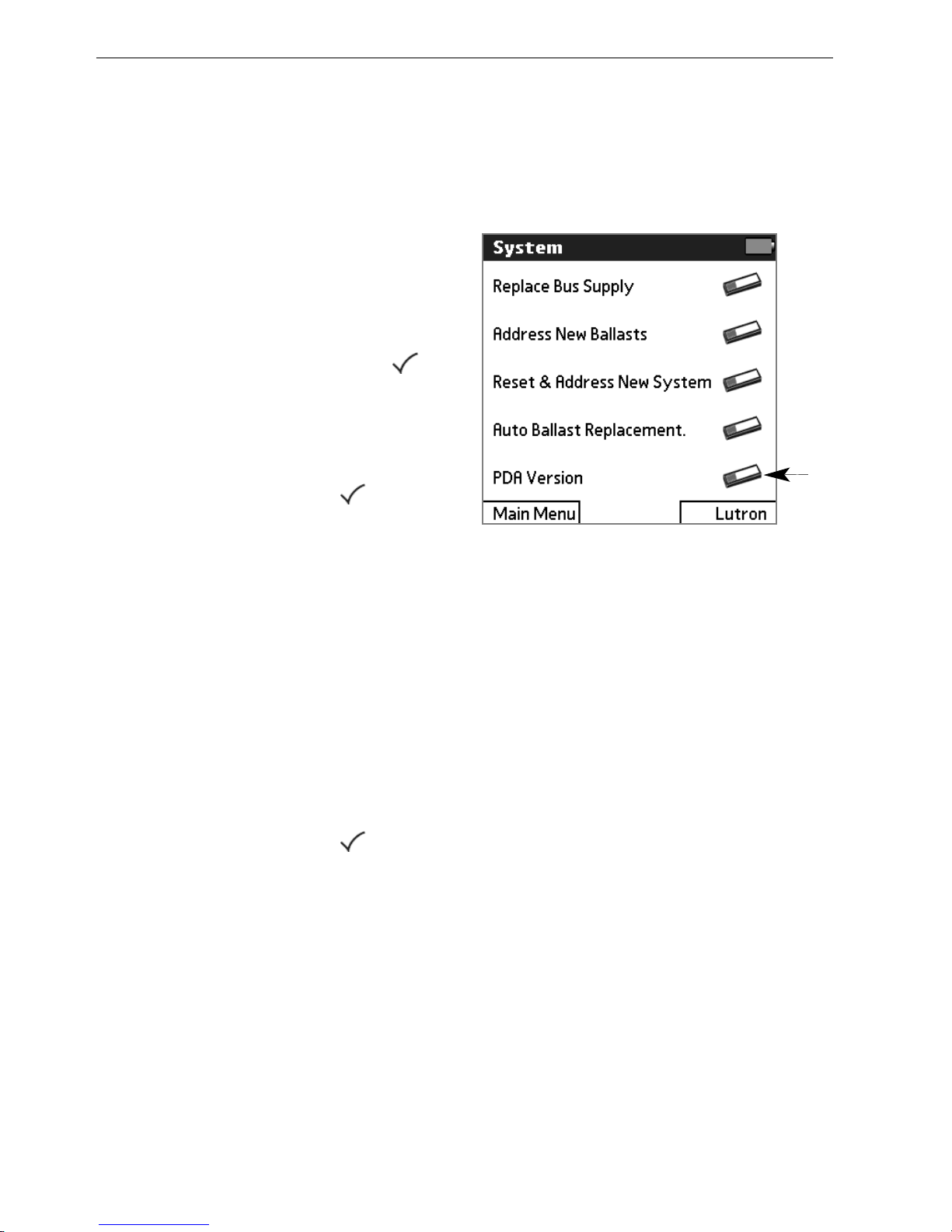
EcoSystem® Programmer Version Check
The version check feature allows you to confirm that the software
version of your PDA is compatible with the software in the bus
supply.
11
From the Main Menu, tap
SSyysstteemm
then
PPDDAA VVeerrssiioonn
.
22
Read the instructions. Point
the programmer at any IR
control device, then tap to
continue.
33
Tap
BBeeggiinn
.
44
If all ballasts flash and go to
their high level, tap .
55
The current EcoSystem
Programmer PDA version will
be selected. Tap
SSeenndd
to test
if that version is compatible
with the bus supply.
If the bus supply is
compatible, the lights will
flash.
66
Select
DDoonnee
.
77
If all ballasts flash and go to
their high level, tap .
11
Page 67

Index
3 wire input 54
AA
addressing the system
addressing a new system 12
addressing new ballasts 60
overview 10
BB
Back option 7
ballasts
addressing a new system 12
addressing new ballasts 60
automatic replacement 61
BMJ/XPJ settings 32
configuring 10, 28
connecting to bus 3
icon 7
limiting restrikes 36
replacing 58
resetting a ballast 63
resetting the entire system 62
seasoning new lamps 10, 31
serial numbers 58
setting occupied/unoccupied
level 37
setting the egress level 38
setting the emergency level 30
setting the high end trim 29
stand-alone programming 46
battery
battery life 7
charging 4, 9
BMJ/XPJ settings
configuring 32
setting on and off level 33
setting the gain 34
setting the mode 35
bus supply 57
CC
contact closures
configuring 10, 41
occupancy timeout 45
occupied or unoccupied level
44
setting the demand response
level 43
setting the mode 42
control devices
configuring fixture groups 10,
16
contact closures 22, 24
daylight sensors 18
icons 7
occupant sensors 20, 24
transmitting to 4
wall controls 26
Page 68

66 EcoSystem® Programmer
DD
daylight level 18
daylight low end 39
daylight off delay 40
daylight sensors
configuring fixture groups 16
daylight off delay 40
icon 7
setting the daylight level 18
setting the low end 39
stand-alone programming 51
demand response level 43
device setup
contact closures 22
daylight sensors 18
occupant sensors 20, 24
overview 10
stand-alone programming 46
wall controls 26
EE
EcoSystem
basic operations 5
maintaining your system 55
overview 3
priority of inputs 11
programmer version check 64
programming workflow 10
stand-alone programming 46
EcoSystem bus 3
egress level 38
emergency level 30
stand-alone 48
FF
fixture groups. See grouping
fixtures
GG
gain 34
grouping fixtures
overview 10
procedure 16
HH
high end trim 29
stand-alone 49
II
icons 7
inputs to EcoSystem 11
IR receivers 3, 4
configuring fixture groups 16
icon 7
LL
lamps, seasoning 10, 31, 50
light levels
contact closures 22
daylight sensors 18
emergency 30
manually adjusting 56
occupied/unoccupied 20, 22,
37, 44
scenes 26
stand-alone programming 46
logging in 6
logging out 9
Page 69

Programming Guide 67
MM
Main Menu 6
manual lighting adjustments 56
OO
occupancy timeout 24, 45
occupant sensors
configuring fixture groups 16
icon 7
setting additional timeouts 24
setting light levels 20, 37
stand-alone programming 52
occupied light levels 20, 22, 37,
44
PP
phase control dimming signal 54
PIN 6
power button 5
programmer
charging 9
power button 5
transmitting 4
programming workflow 10
prompt screens 8
RR
replacing ballasts 58
resetting a single ballast 63
resetting the entire system 62
restrikes, limiting 36
SS
scenes 26
screens
Back option 7
making selections 6
prompt screens 8
screen components 7
viewing battery life 7
seasoning new lamps 10, 31
stand-alone 50
serial numbers 58
stand-alone programming 46
3 wire input 54
daylight sensors 51
emergency level 48
high end trim 49
lamp seasoning 50
occupant sensors 52
stylus 5, 6
TT
timeouts 24, 45
UU
unoccupied light levels 20, 22,
37, 44
VV
version check 64
WW
wall controls
configuring fixture groups 16
setting up scenes 26
XX
XPJ settings 32, 53
Page 70

Limited Warranty
(Valid only in U.S.A., Canada, Puerto Rico, and the Caribbean.)
For a period of one year from the date of purchase, and subject to the exclusions and restrictions described below,
Lutron warrants each new unit to be free from manufacturing defects. Lutron will, at its option, either repair the
defective unit or issue a credit equal to the purchase price of the defective unit to the Customer against the purchase
price of comparable replacement part purchased from Lutron. Replacements for the unit provided by Lutron or, at its
sole discretion, an approved vendor may be new, used, repaired, reconditioned, and/or made by a different
manufacturer. If the unit is commissioned by Lutron or a Lutron approved third party as part of a Lutron commissioned
lighting control system, the term of this warranty will be extended, and any credits against the cost of replacement
parts will be prorated, in accordance with the warranty issued with the commissioned system, except that the term of
the unit's warranty term will be measured from the date of its commissioning.
EXCLUSIONS AND RESTRICTIONS
This Warranty does not cover, and Lutron and its suppliers are not responsible for: Damage, malfunction or
inoperability diagnosed by Lutron or a Lutron approved third party as caused by normal wear and tear, abuse,
misuse, incorrect installation, neglect, accident, interference or environmental factors, such as (a) use of incorrect line
voltages, fuses or circuit breakers; (b) failure to install, maintain and operate the unit pursuant to the operating
instructions provided by Lutron and the applicable provisions of the National Electrical Code and of the Safety
Standards of Underwriter's Laboratories; (c) use of incompatible devices or accessories; (d) improper or insufficient
ventilation; (e) unauthorized repairs or adjustments; (f) vandalism; or (g) an act of God, such as fire, lightning,
flooding, tornado, earthquake, hurricane or other problems beyond Lutron's control. On-site labor costs to diagnose
issues with, and to remove, repair, replace, adjust, reinstall and/or reprogram the unit or any of its components.
Equipment and parts external to the unit, including those sold or supplied by Lutron (which may be covered by a
separate warranty).
The cost of repairing or replacing other property that is damaged when the unit does not work properly, even if the
damage was caused by the unit.
Except AS EXPRESSLY PROVIDED IN this warranty, THERE ARE NO EXPRESS OR IMPLIED WARRANTIES
OF ANY TYPE, INCLUDING ANY IMPLIED WARRANTIES OF FITNESS FOR A PARTICULAR PURPOSE OR
MERCHANTABILITY. LUTRON DOES NOT WARRANT THAT THE UNIT WILL OPERATE WITHOUT
INTERRUPTION OR BE ERROR FREE. NO LUTRON AGENT, EMPLOYEE OR REPRESENTATIVE HAS ANY
AUTHORITY TO BIND LUTRON TO ANY AFFIRMATION, REPRESENTATION OR WARRANTY CONCERNING
THE UNIT. UNLESS AN AFFIRMATION, REPRESENTATION OR WARRANTY MADE BY AN AGENT, EMPLOYEE
OR REPRESENTATIVE IS SPECIFICALLY INCLUDED HEREIN, OR IN STANDARD PRINTED MATERIALS
PROVIDED BY LUTRON, IT DOES NOT FORM A PART OF THE BASIS OF ANY BARGAIN BETWEEN LUTRON
AND CUSTOMER AND WILL NOT IN ANY WAY BE ENFORCEABLE BY CUSTOMER.
IN NO EVENT WILL LUTRON OR ANY OTHER PARTY BE LIABLE FOR EXEMPLARY, CONSEQUENTIAL,
INCIDENTAL OR SPECIAL DAMAGES (INCLUDING, BUT NOT LIMITED TO, DAMAGES FOR LOSS OF
PROFITS, CONFIDENTIAL OR OTHER INFORMATION, OR PRIVACY; BUSINESS INTERRUPTION; PERSONAL
INJURY; FAILURE TO MEET ANY DUTY, INCLUDING OF GOOD FAITH OR OF REASONABLE CARE;
NEGLIGENCE, OR ANY OTHER PECUNIARY OR OTHER LOSS WHATSOEVER), NOR FOR ANY REPAIR
WORK UNDERTAKEN WITHOUT LUTRON'S WRITTEN CONSENT arising out of or in any way related to the
installation, deinstallation, use of or inability to use THE unit or otherwise under or in connection with any
provision of this warranty, or any agreement incorporating this warranty, even in the event of the fault, tort
(including negligence), strict liability, breach of contract or breach of warranty of Lutron or any supplier, and
even if Lutron or any OTHER PARTY was advised of the possibility of such damages.
Notwithstanding any damages that Customer might incur for any reason whatsoever (including, without
limitation, all direct damages and all damages LISTED above), the entire liability of Lutron and of all OTHER
PARTIES under this Warranty ON ANY CLAIM FOR DAMAGES ARISING OUT OF OR IN CONNECTION WITH
THE MANUFACTURE, SALE, INSTALLATION, DELIVERY, USE, REPAIR, OR REPLACEMENT OF THE UNIT, or
any Agreement incorporating this Warranty, and Customer's SOLE remedy for the foregoing, will be limited to
the amount paid to Lutron by Customer for the unit. The foregoing limitations, exclusions and disclaimers
will apply to the maximum extent ALLOWed by applicable law, even if any remedy fails its essential purpose.
TO MAKE A WARRANTY CLAIM
To make a warranty claim, promptly notify Lutron within the warranty period described above by calling the Lutron
Technical Support Center at (800) 523-9466. Lutron, in its sole discretion, will determine what action, if any, is
required under this warranty. To better enable Lutron to address a warranty claim, have the unit's serial and model
numbers available when making the call. If Lutron, in its sole discretion, determines that an on-site visit or other
remedial action is necessary, Lutron may send a Lutron Services Co. representative or coordinate the dispatch of a
representative from a Lutron approved vendor to Customer's site, and/or coordinate a warranty service call between
Customer and a Lutron approved vendor.
This product may be covered under the following U.S. Patent: 7,391,297; and corresponding foreign patents. U.S.
and foreign patent(s) pending.
Lutron is a registered trademark of Lutron Electronics Co., Inc. EcoSystem is a trademark of Lutron Electronics Co.,
Inc. National Electric Code and NEC are registered trademarks of the National Fire Protection Association, Quincy,
Massachusetts. © 2009 Lutron Electronics Co., Inc.
Page 71

Page 72

wwwwww..lluuttrroonn..ccoomm
WWOORRLLDD
HHEEAADDQQUUAARRTTEERRSS
USA
Lutron Electronics Co., Inc.
7200 Suter Road
Coopersburg, PA 18036-1299
TEL +1.610.282.3800
FAX +1.610.282.1243
Toll-Free 1.888.LUTRON1
Technical Support 1.800.523.9466
NNoorrtthh aanndd SSoouutthh AAmmeerriiccaa TTeecchhnniiccaall HHoottlliinneess
USA, Canada, Caribbean: 1.800.523.9466
Mexico: +1.888.235.2910
Central/South America: +1.610.282.6701
©9/2009 Lutron Electronics Co., Inc. | Made and printed in the U.S.A. | P/N 032229 Rev A
 Loading...