

Page 1
Green power, hybrid power
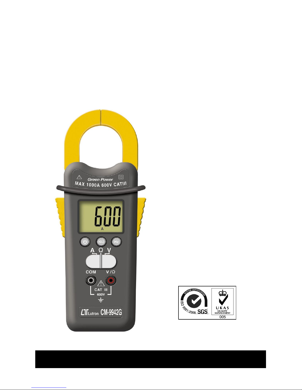
SMART
CLAMP METER
Model : CM-9942G
Your purchase of this
SMART CLAMP METER
marks a step forward for
you into the field of
precision measurement.
Although this CLAMP
METER is a complex and
delicate instrument, its
durable structure will allow
many years of use if
p r o p e r o p e r a t i n g
techniques are developed.
Please read the following
instructions carefully and
always keep this manual
within easy reach.
OPERATION MANUAL
Page 2
Caution Symbol
Caution :
* Risk of electric shock !
Caution :
* Do not apply the overload
voltage, current to the input
terminal !
* Remove test leads before open
the battery cover !
* Cleaning - Only use the dry
cloth to clean the plastic case !
Environment Conditions
* Installation Categories III 600V.
* Pollution Degree 2.
* Altitude up to 2000 meters.
* Indoor use.
* Relative humidity 80% max.
Equipment protected throughout
by double insulation or reinforced
insulation.
Page 3

TABLE OF CONTENTS
1. FEATURES..........................................................................
1
2. SPECIFICATIONS................................................................
2
2-1 General Specifications............................................
2
2-2 Electrical specifications.............................................
4
3. FRONT PANEL DESCRIPTION..................................................................
6
3-1 Current Sense Jaws........................................... 6
3-2 Trigger .............................................................. 6
3-3 Display................................................................
6
3-4 Power On/Off button.......................................... 6
3-5 Hold button....................................................... 6
3-6 Hz button........................................................... 6
3-7 Function slide switch .......................................... 6
3-8 V/Ω terminal ......................................................
6
3-9 COM terminal .................................................. 6
3-10 Handle of power generator................................ 6
3-11 Power type switch ( G/B switch )...................... 6
3-12 Battery compartment/cover................................ 6
4. POWER TYPE SELECTION........................................ 7
4-1 Power supply from the generator ( Green
power supply ) ....................................................
7
4-2 Power supply from the battery................................
8
5.
MEASURING PROCEDURE.......................................................................
8
5-1 precautions & preparations for measurement...... 8
5-2 Power management.............................................
8
5-3 Symbols & units of display.....................................
9
5-4 AC Current Measurement ......................................
10
5-5 Voltage ( ACV/DCV ) measurement.........................
10
5-6 Resistance measurement......................................
11
5-7 Continuity, Diode measurement..............................
11
5-8 Capacitance Measurement........................................
13
5-9 Frequency measurement....................................................
14
5-10 Auto power off.....................................................................
14
6.
MAINTENANCE.......................................................................
14
7.
OPTIONAL ACCESSORIES & ADAPTERS ..................................................
16
8. PATENT.....................................................................
16
9. THE ADDRESS OF AFTER SERVICE CENTER.....................
17
Page 4

1. SPECIFICATIONS
* Green power, battery is no need, power supply from
the handy generator, operate the generator 30 to 60
seconds will offer 15 to 20 minutes energy typically.
* Hybrid power, meter's power also can supply by the
battery,
* Green power internal charge system use the Super
charge capacitor, fast charge time and high reliability.
* Meet CAT III-600 V.
* 6000 counts A/D, high resolution.
* ACV, ACA, DCV, ohms, continuity, Hz, Capacitance,
Diode, Data hold.
* Smart function, Auto range.
* Smart operation, Build in 4 intelligent function :
" A ", " Ω ", " V ".
* " A " function can measure ACA with auto range.
* " V " function can select ACV, DCV automatically with
auto range.
* " Ω " function can select the Resistance , Diode,
Continuity beeper, Capacitance automatically with auto
range.
* Data hold function for ACA measurement.
* Auto shut off is available to save battery life.
* 10 M ohm impedance for voltage circuit.
* Built-in overload protection for most ranges.
* LSI circuit provides high reliability and durability.
* Patent.
* Uses durable, long-lasting components, enclosed in
strong, light weight ABS-plastic housing.
* Full line optional adapters : Clamp adapter,
Tachometer adapter, Pressure adapter, Humidity
Adapter, Sound level adapter, Anemometer adapter,
Light adapter, EMF adapter.
1
Page 5
2. SPECIFICATIONS
2-1 General Specifications
Green power * Green power, battery is no need,
and power supply from the handy
Hybrid power generator, operate 30 to 60
seconds the generator will offer 15
to 20 minutes energy typically.
Green power internal charge system
use the Super charge capacitor, fast
charge time and high reliability.
* Hybrid power, meter also can supply
by the battery power.
Display 40 mm x 30.3 mm large LCD display.
Measurement ACV, ACA, DCV, DCA, ohms,
continuity beeper, Hz, Capacitance,
Diode, Data hold.
A/D counts no. 6000 counts.
Range selection Smart function, auto range.
Smart function " A " function can measure ACA with
auto range.
" V " function can select ACV, DCV
automatically with auto range.
" Ω " function can select the Resistance,
Diode, Continuity beeper, Capacitance
automatically with auto range.
Data hold To freeze the display reading on the
LCD display.
* Available for ACA measurement only.
Power On/Off Manual power off.
management Auto power off :
If meter is not operated within 10
minutes will auto power switch off.
2
Page 6
Polarity Automatic Switching, " - " indicates
negative polarity.
Max. jaw open 42 mm ( 1.65 inch ) Dia.
size
Zero adjustment
Automatic.
Sampling time Approx. 0.5 to 1 second.
Operating 0 to 50 (32 to 122 ).℃ ℉
temperature
Operating Less than 80% RH.
humidity
Power Green power :
Supply Power from the handy generator,
battery is no need.
Battery power :
DC3V battery ( CR-2032 ) x 2 PCs.
Power DC 3.9 mA.
consumption
Weight 310 g/068 LB.
Dimension 228 x 85.7 x 45.6 mm
( 9.0 x 3.4 x 1.8 inch )
Accessories
Red and Black Test Leads.............
1 Set
Included
Instruction Manual.................................................
1 PC
Optional Carrying case : CA-05A.
accessories Full line adapters :
ACA/DCA current adapter,
Tachometer adapter,
Humidity adapter, Pressure adapter,
Light adapter, EMF adapter,
Sound level adapter,
High voltage probe.
3
Page 7

2-2 Electrical specifications (23± 5 )℃
DC/AC Voltage
* auto range
Range 6 V /60 V/600 V
Resolution 0.001 V /0.01 V/0.1 V
Accuracy DCV : ± ( 1 % + 2d )
ACV : ± ( 1.2 % + 5d )
Input impedance 10 M ohm.
Over load AC/DC 600 V.
protection
Remark
* The input impedance is 10 Mega ohm.
* ACV specification be tested on sine
wave 50/60 Hz.
* For smart function ,the ACV start
measurement voltage is larger than
400 mV ± 100 mV.
AC Current
* auto range
Range 600 A/1000 A
Resolution 0.1 A/1 A
Accuracy 600 A range ± ( 1.5% + 2d )
1000 A range ± ( 2% + 8d )
Over load AC 1000A.
protection
Remark
* ACA specification be tested on sine
wave 50/60 Hz.
* Measurement range :
measurement is
0.1A to 1000 A
OHMS
* auto range
Range 600/6 K/60 K/600 K/6 M ohm
Resolution 0.1/1/10/100/1 K ohm
Accuracy ± ( 1% + 3d )
Over load ± 400 DCV, 350 ACV
protection
4
Page 8

Capacitance
* auto range
Range 6 nF/60 nF/600 nF/6 uF/60 uF
Resolution 0.001 nF/0.01 nF/0.1 nF/0.001 uF/
0.01 uF
Accuracy ± ( 3% + 5d )
Remark
Discharge capacitor before testing.
Frequency
Range 40 Hz to 1 KHz.
Resolution 1 Hz.
Accuracy ± ( 0.3% + 2d )
Input impedance 10 M ohm.
Over load AC/DC 600 V.
protection
Diode
Short/non conductance, good/defect test.
Continuity
If measuring resistance is less than 10 ohm, the beeper
will sound .
5
Page 9

3. FRONT PANEL DESCRIPTION
Fig. 1
3-1 Current Sense Jaws
3-2 Trigger
3-3 Display
3-4 Power On/Off button.
3-5 Hold button
3-6 Hz button
3-7 Function slide switch
3-8 V/Ω terminal
3-9 COM terminal
3-10 Handle of power generator
3-11 Power type switch ( G/B switch )
3-12 Battery compartment/cover
6
Page 10
4. POWER TYPE SELECTION
4-1 Power supply from the generator
( Green power supply )
1)
Select the " Power type switch " ( 3-11, Fig. 1 ) to
the " G position " ( Green power position ).
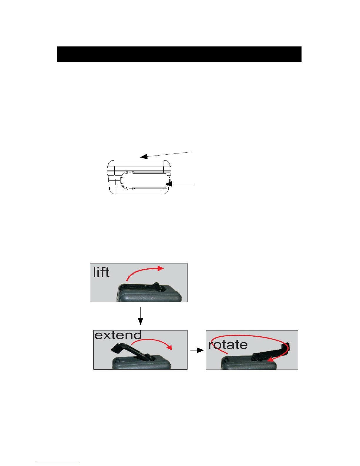
There is a " Power generator's handle " ( 3-10, Fig. 1 )
on the bottom of the housing case.
LCD display
Power generator's handle
2)Lift and extend the " Power generator's handle "
and rotate the handle in clockwise direction will
generate the power energy into the meter, refer
to Fig. a, b, c.
Fig. a
Fig. c
Fig. b
c. Wind-up the generator 30 to 60 seconds will offer 15
to 20 minutes energy typically. If wind-up the generator
more time, the meter will be saved more energy and
let the meter be operated for a long period.
7
Page 11

4-2 Power supply from the battery
1)Install the " DC3V battery ( CR-2032 ) x 2 PCs "
into the " Battery compartment " ( 3-12, Fig. 1)
2)Slide the " Power type switch " to the " B " position (
battery position ), the meter will offer the power
source from the battery.
5. MEASURING PROCEDURE
5-1 precautions & preparations for measurement
1)Place the Red & Black Test Leads into
the proper input terminal before
making measurement.
2)Remove either of the test leads from
the circuit when changing the
measurement range.
3)Do not exceed the maximum rated voltage
to the input terminal.
4)Do not exceed the maximum rated
current to " Current sensing Jaws.
5)For safety consideration, when change
the new test leads, it should use the
replace approval test leads.
5-2 Power management
1)Pressing the " Power On button " ( 3-4, Fig. 1 ) once,
the meter will be power On.
Pressing the " Power On button " ( 3-4, Fig. 1 ) once
again, the meter will be power Off..
2)The meter will be power Off automatically within
10 minutes after power On.
8
Page 12
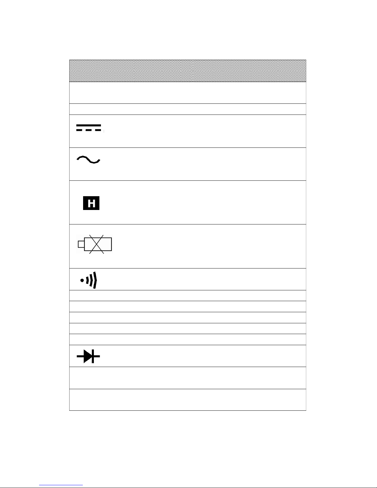
5-3 Symbols & units of display
Symbols Descriptions
Units
SMART Appears when selecting " Smart " mode.
The meter default mode is " Smart "
AUTO Appears when selecting " Automatic range " mode.
Appears when selecting DC mode.
( DC voltage )
DC
Appears when selecting AC mode.
( AC voltage or AC current )
AC
* Appears when the " Data hold " function is
operated.
* " Data hold " function is available for the
ACA measurement only.
Power voltage is already under the low condition.
Appears when the " Continuity " is operated.
mV, V Units for voltage measurements.
A Units for " Current " measurement.
Ω ,KΩ ,MΩ Units for resistance measurements.
nF,uF Units for " Capacitance " measurement.
KHz Units for " Frequency " measurement.
Appears when the " Diode " function is operated.
- Appears when measuring a DCV value is
negative.
OL Over range indicator for voltage, current,
ohm and capacitance function.
9
Page 13
5-4 AC Current Measurement
1)Select the " Function switch " ( 3-7, Fig. 1 ) to the
" A " position.
2)Power On the meter by pressing the " Power On/Off
button " ( 3-4, Fig. 1 ) once, the Display will show
" AC " , " A " and " AUTO " indicator, now the meter is
under " Auto range " current measurement.
3)Press the " Trigger " ( 3-2, fig. 1 ) to open the
" Current Sensor Jaws " ( 3-1, Fig. 1 ) and clamp on
the measured conductor, the display will show the
measurement ACA current value automatically ( auto range ).
Data hold for Current measurement
1)During the current measurement, if press the " Hold button "
( 3-5, Fig. 1 ) will freeze the measurement current value.
In the same time the Display will show " " and
" MANU " indicator.
2)Push the " Hold Button " again to release the data hold
function.
Remark :
The Data Hold operation is only available for the
" ACA measurement ", not available for other
functions.
5-5 Voltage ( ACV/DCV ) measurement
1)Connect BLACK test lead into " COM " terminal ( 3-9,
Fig. 1 ).
2)Connect RED test lead into " V " terminal ( 3-8, Fig. 1 ).
3)Select the " Function switch " ( 3-7, Fig. 1 ) to
the " V " position.
10
Page 14

4)Power On the meter by pressing the " Power On/Off
button " ( 3-4, Fig. 1 ) once, the Display will show "
SMART ", the meter is under " Smart " mode for
voltage measurement.
5)The meter can measure the ACV, DCV value automatically
and with auto range selection.
5-6 Resistance measurement
1)Connect BLACK test lead into " COM " terminal ( 3-9,
Fig. 1 ).
2)Connect RED test lead into " Ω " terminal ( 3-8, Fig. 1 ).
3)Select the " Function switch " ( 3-7, Fig. 1 ) to
the " Ω " position.
4)Power On the meter by pressing the " Power On/Off
button " ( 3-4, Fig. 1 ) once, the Display will show "
SMART ", the meter is under " Smart " mode for
resistance measurement.
5)The meter can measure the resistance value automatically
and with auto range selection.
5-7 Continuity, Diode measurement
Continuity measurement
1)Connect BLACK test lead into " COM " terminal ( 3-9,
Fig. 1 ).
2)Connect RED test lead into " Ω " terminal ( 3-8, Fig. 1 ).
3)Select the " Function switch " ( 3-7, Fig. 1 ) to the " Ω "
position.
4)Power On the meter by pressing the " Power On/OFF
button " ( 3-4, Fig. 1 ) once, the Display will show "
SMART ", the meter is under " Smart " mode for
Continuity measurement.
11
Page 15

5)
When the resistance value is less than 10 ohm, the
beeper sound will be generated, the Display will
show " " and " Ω " indicator.
Diode measurement
1)Connect BLACK test lead into " COM " terminal ( 3-9,
Fig. 1 ).
2)Connect RED test lead into " Ω " terminal ( 3-8, Fig. 1 ).
3)Select the " Function switch " ( 3-7, Fig. 1 ) to
" Ω " position.
4)Power On the meter by pressing the " Power On/Off
button " ( 3-4, Fig. 1 ) once, the Display will show "
SMART ", the meter is under " Smart " mode for
Diode measurement.
5)a. When connected with polarity as shown in Fig. 2, a
forward current flow is established and the approx.
Diode Forward Voltage (VF) value in volt will
appears on the display reading. If the diode under
test is defective, " .000 " or near " .000 " value
( short circuit ) or " OL " ( open circuit ) will be
displayed.
Fig. 2
12
Page 16

b. When connected as shown in Fig. 3, a reverse check
on the diode is made. If the diode under test is
good, " OL " will be displayed. If the diode under
test is defective, " .000 " or other numbers will be
displayed. Proper diode testing should include both
steps a. and b. above.
Fig. 3
5-8 Capacitance Measurement
1)Connect BLACK test lead into " COM " terminal ( 3-9,
Fig. 1 ).
2)Connect RED test lead into " Ω " terminal ( 3-8, Fig. 1 ).
3)Select the " Function rotary switch " ( 3-7, Fig. 1 ) to
the " Ω " position.
4)Power On the meter by pressing the " Power On/Off
button " ( 3-4, Fig. 1 ) once, the Display will show "
SMART ", the meter is under " Smart " mode for
capacitance measurement.
5)The meter can measure the capacitance value automatically
and with auto range selection.
13
Page 17

5-9 Frequency measurement
During the measurement :
a. AC Current measurement ( Chapter 5-4, page 10 )
b. Voltage ( ACV/DCV ) measurement ( Chapter 5-5, page 10 )
If press the " Hz button " ( 3-6, Fig. 1 ) once, the Display
will show " AUTO " and " K Hz " indicator, now the meter
is ready for frequency measurement of the
measurement signal with auto range indication.
If press the " Hz button " ( 3-6, Fig. 1 ) once again
will release the Hz measurement function and return
to normal measuring Display.
5-10 Auto power off
The meter build the auto power off after power On to
extend the battery life. After auto power off.
Press the " Power On/Off button " ( 3-4, Fig. 1 ) once
will Power On again.
6. MAINTENANCE
Caution :
Remove test leads before
opening the battery cover
or housing case !
6-1 Cleaning
Caution :
Cleaning - Only use
the dry cloth to clean
the plastic case !
14
Page 18

6-2 Replacement of batteries ( Battery power )
1)When use the battery power, if the Display show
Low battery indicator " " , it need to change
the batteries.
2)open the " Battery Cover " ( 3-12, Fig. 1 ) away from the
instrument and remove the battery.
3)Replace with batteries ( DC 3V, CR2032 X 2 PCs )
and reinstate the cover.
* When install the batteries, should make
attention the battery polarity.
4)Make sure the battery cover is secured after changing
the batteries.
Remark :
During the LCD show the Low battery indicator " ",
if the buzzer sound continuously, it is normal.
For power supply from the generator
Wind-up the Generator, until the meter is charged
completely, will switch off the buzzer sound and
return to normal condition.
For power supply from the battery
Replace with batteries ( DC 3V, CR2032 X 2 PCs )
will switch off the buzzer sound and return to normal
condition.
15
Page 19

7. OPTIONAL ACCESSORIES
and ADAPTERS
Item Model
Carrying Case CA-03, CA-05A
Light Adapter LX-02
EMF Adapter EMF-824
Pressure Adapter PS-403
Anemometer Adapter AM-402
Tachometer Adapter TA-601
Sound Adapter SL-406
High Voltage Probe HV-40
8. PATENT
CHINA : ZL200620012764.3
GERMANY : Nr.202006007329.9
TAIWAN : M299401
JAPAN : 3130269
U.S.A. : PATENT PENDING
16
Page 20

9. THE ADDRESS OF AFTER SERVICE
CENTER
17
0908-CM9942G
 Loading...