

Page 1
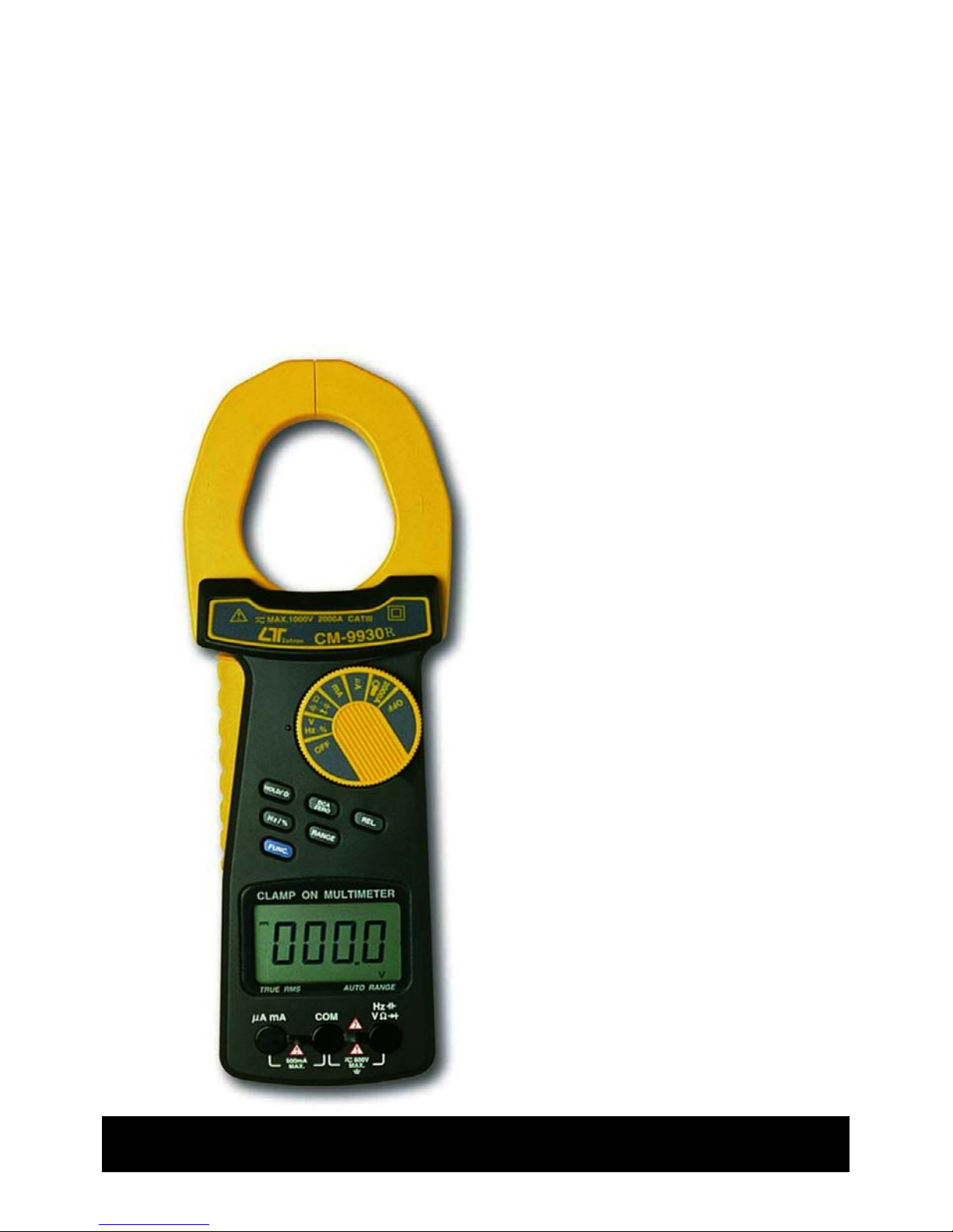
2000 A DCA/ACA CLAMP + DMM, true rms
RS232/USB Computer interface
DCA/ACA
CLAMP METER
Model : CM-9930R
Your purchase of this
DCA/ACA CLAMP
METER with RS232/USB
computer interface
marks a step forward for
you into the field of
precision measurement.
Althou
g
h this CLAMP
METER is a complex and
delicate instrument, its
durable structure will
allow many years of use
if proper operatin
g
techniques are
developed. Please read
the followin
g
instructions carefully
and always keep this
manual within easy
reach.
OPERATION MANUAL
Page 2
Caution Symbol
Caution :
* Risk of electric shock !
Caution :
* Do not apply the overload
voltage, current to the input
terminal !
* Remove test leads before open
the battery cover !
* Cleaning - Only use the dry
cloth to clean the plastic case !
Environment Conditions
* Installation categories III .
* Pollution Degree 2.
* Altitude up to 2000 meters.
* Relative humidity 80% max.
Page 3

TABLE OF CONTENTS
1. FEATURES..........................................................1
2. SPECIFICATIONS............................................... 1
2-1 General Specifications...................................
.
1
2-2 Electrical Specifications.................................
.
2
3. FRONT PANEL DESCRIPTION..............................
.
4
4. PRECAUTIONS & PREPARATIONS FOR
MEASUREMENT..................................................
.
5
5. MEASURING PROCEDURE...................................
.
6
5-1 Symbols & Units of Display ............................... 6
5-2 DCV, ACV Measurement ..................................
.
7
5-3 Resistance Measurement................................... 7
5-4 Continuity Check .............................................. 7
5-5 Diode Test ....................................................... 8
5-6 AC Current Measurement ( Clamp on )............... 9
5-7 DC Current Measurement ( Clamp on )............... 9
5-8 AC Current Measurement ( Direct input ) ...........10
5-9 DC Current Measurement ( Direct input ) ...........10
5-10 Capacitance Measurement.................................11
5-11 Frequency Measurement................................... 11
5-12 Duty Cycle Measurement...................................12
5-13 Data Hold Operation.........................................
.
12
5-14 Relative Operation............................................
.
12
5-15 Back Light Operation.........................................12
6. MAINTENANCE................................................... 13
6-1 Replacement of Battery................................. 13
6-2 Replaacement of Fuse................................... 13
7. RS232 PC SERIAL INTERFACE.............................14
8. OPTIONAL ACCESSORIES & ADAPTERS ..............
.
16
9. THE ADDRESS OF AFTER SERVICE CENTER.........17
Page 4
1. FEATURES
* 2 in 1, 2000 A clamp meter + Digital multimeter.
* Design meet IEC 1010 CATIII 1000V safety requirement.
* True rms reading for ACV & ACA measurement.
* 4000 counts, Auto range, multi-functions for ACA,
DCA, ACV, DCV, Ohms, Capacitance, Hz, Duty cycle,
diode and continuity check.
* Wide ranges ( 2000A, 400 A ) clamp on current
measurement both for ACA & DCA.
* 4 ranges ( 400 uA, 4000 uA, 40 mA, 400 mA ) direct
current input measurement both for ACA & DCA.
* LSI circuit provides high reliability and durability.
* Overload protection circuit is provided for all ranges.
* Data hold, Relative key, Back light.
* RS232/USB PC COMPUTER interface.
* Compact & heavy duty ABS and fireproof plastic case.
2. SPECIFICATIONS
2-1 General Specifications
Display 15 mm (0.6") LCD, 4 digits,
Max. indication 4000.
Measurement ACA, DCA, ACV, DCV, Ohms, Diode, Hz,
Ran
g
e Capacitance, Duty cycle, Continuity beeper.
Polarity Automatic Switching, "-" indicates
ne
g
ative polarity.
Current Sensor Hall effect sensor.
Zero adjustment
DCA :
Push bottom adjustment.
Other ranges
:
Automatic adjustment.
Over-input Indication of " OL " or " -OL ".
Sampling Time Approx. 0.35 second.
Data Output RS 232/USB PC computer interface.
*
Connect the optional RS232 cabl
e
UPCB-02 will get the RS232 plug.
*
Connect the optional USB cabl
e
USB-01 will get the USB plug.
Battery DC 9V battery, heavy duty or Alkaline type,
006P, MN1604 ( PP3) or equivalent.
Power Consump. Approx. DC 5 mA.
1
Page 5
Operating Temp. 0 to 50 (32 to 122 ).℃℃℉ ℉
Operating Less than 80% RH.
Humidity
Weight 380 g/0.85 LB (including battery).
Dimension HWD : 255 x 73 x 38 mm.
(10 x 2.9 x 1.5 inch)
Max. Jaw 51 mm ( 2.1 inch ) Dia.
Open Size
Accessories Operation manual...............................1 PC
Included
T
est lead (red & black)........................1 Set
Fuse ( 500 mA, 5 mm dia. x 20 mm )...1 PC
Optional * RS232 cable........................... UPCB-02
Accessories & * USB cable.............................. USB-01
Adapters * Data Acquisition software
* Refer t
o
..................................SW-U801-WIN
page 1
5
* Carrying case, EMF Adapter,
Li
g
ht Adapter, Anemometer Adapter,
Pressure Adapter, Sound Adapter,
T
achometer Adapter, High Voltage Probe.
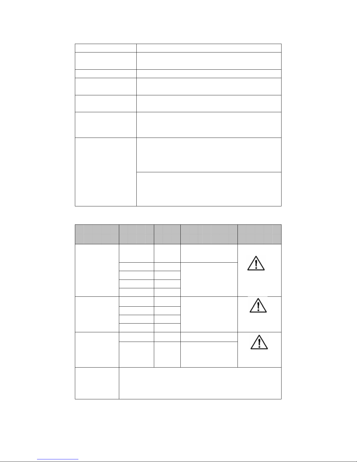
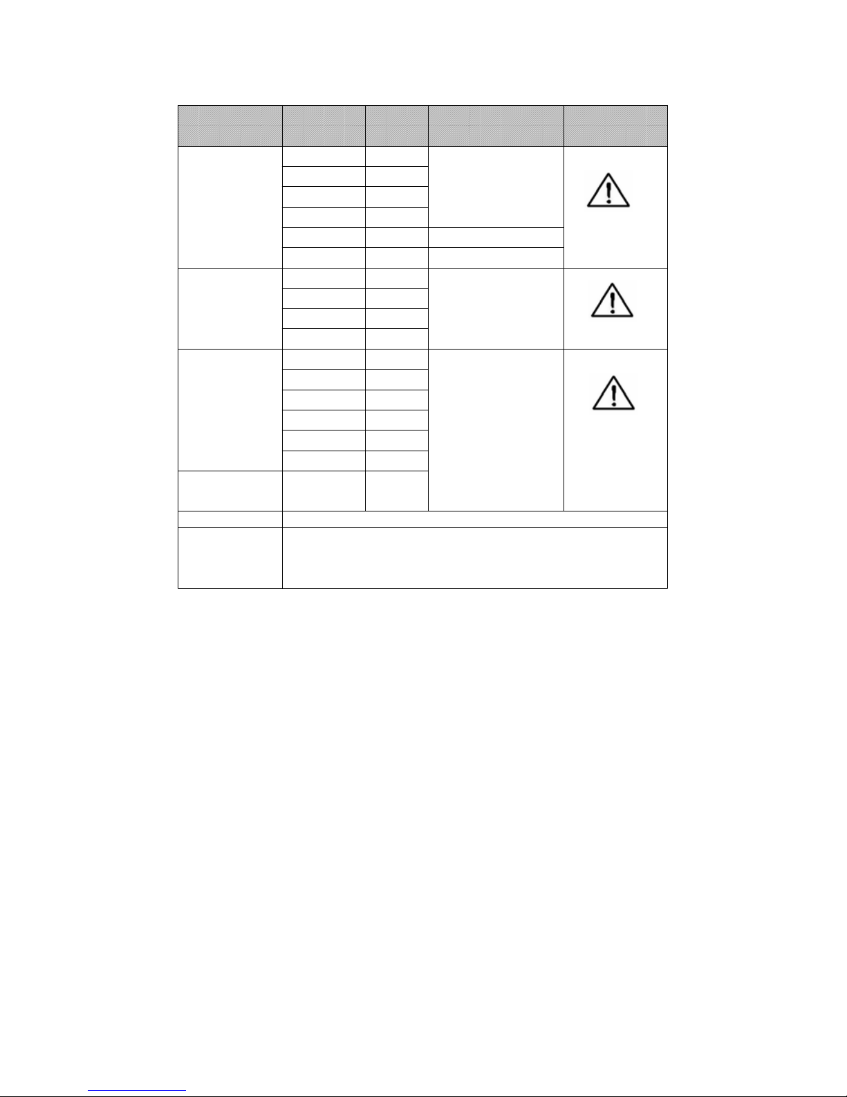
2-2 Electrical Specifications (23 ±5 )℃
Function Range Reso- Accuracy Overload
lution Protection
DC/AC 400 mV 0.1 mV ± ( 0.5 % + 2d )
Voltage (DC only)
4 V 0.001V
DCV:
40 V
0.01V
± ( 1 % + 2d )
400 V 0.1 V
ACV:
AC/DC 1000 V.
1000V 1 V ± ( 1.2 % + 5d )
DC / AC 400 uA 0.1 uA
Current 4000 uA
1 uA
(Direct input) 40 mA 0.01 mA ± ( 1.2% + 5d ) AC/DC 500 mA
400 mA 0.1 mA ( Fuse )
DC /AC 400 A 0.1 A ± ( 2 % + 5 d )
current
(Clamp on)
2000 A
1 A
± ( 2 % + 8 d )
AC/DC
2000A/1000V
Remar
k
* True rms measurement both for ACV, ACA function.
* Input impedance for ACV & DCV range is 10 Mega ohm.
* ACA, ACV frequency response is from 45 to 1 KHz.
* ACA, ACV specification be tested on sine wave 50/60 Hz.
2
Page 6
Function RangeReso-Accurac
y
Overload
lution Protection
Ohms 400 ohm 0.1 ohm
4 K ohm 1 ohm
40 K ohm 10 ohm ± ( 1 % + 5 d )
400 K ohm 100 ohm
4 M ohm 1 K ohm ± ( 2 % + 2 d ) AC / DC 400V
40 M ohm 10Kohm ± ( 3.5 % + 5d )
Capacitance
50 nF 10 pF
500 nF 100 pF
5 uF 0.001 uF
± ( 3 % + 5d )
50 uF 0.01 uF
* See Remark
AC / DC 400V
Frequency 5 Hz 0.001 Hz
( > 5 V )
50 Hz 0.01 Hz
500 Hz 0.1 Hz
5 KHz 1 Hz
± (1 % + 5 d)
50 KHz 0.01 KHz
100 KHz 0.1 KHz AC / DC 1000V
Duty cycle 1 % to 0.1 %
99 %
Diod
e
Short/
non conductance, goo
d/defect test
Continuity If rmeasuring esistance is less than 10 ohm, the
beeper will sound .
Remark
:
*Spec. tested under the environment RF Field Strengt
h
less than 3 V/M & frequency less than the 30 MHz only.
*
T
he accuracy of capacitance range are specified under tha
t
the " zero " procedure is executed before the measuremen
t
( push " REL. button, refer 5-10, page 11 ).
3
Page 7
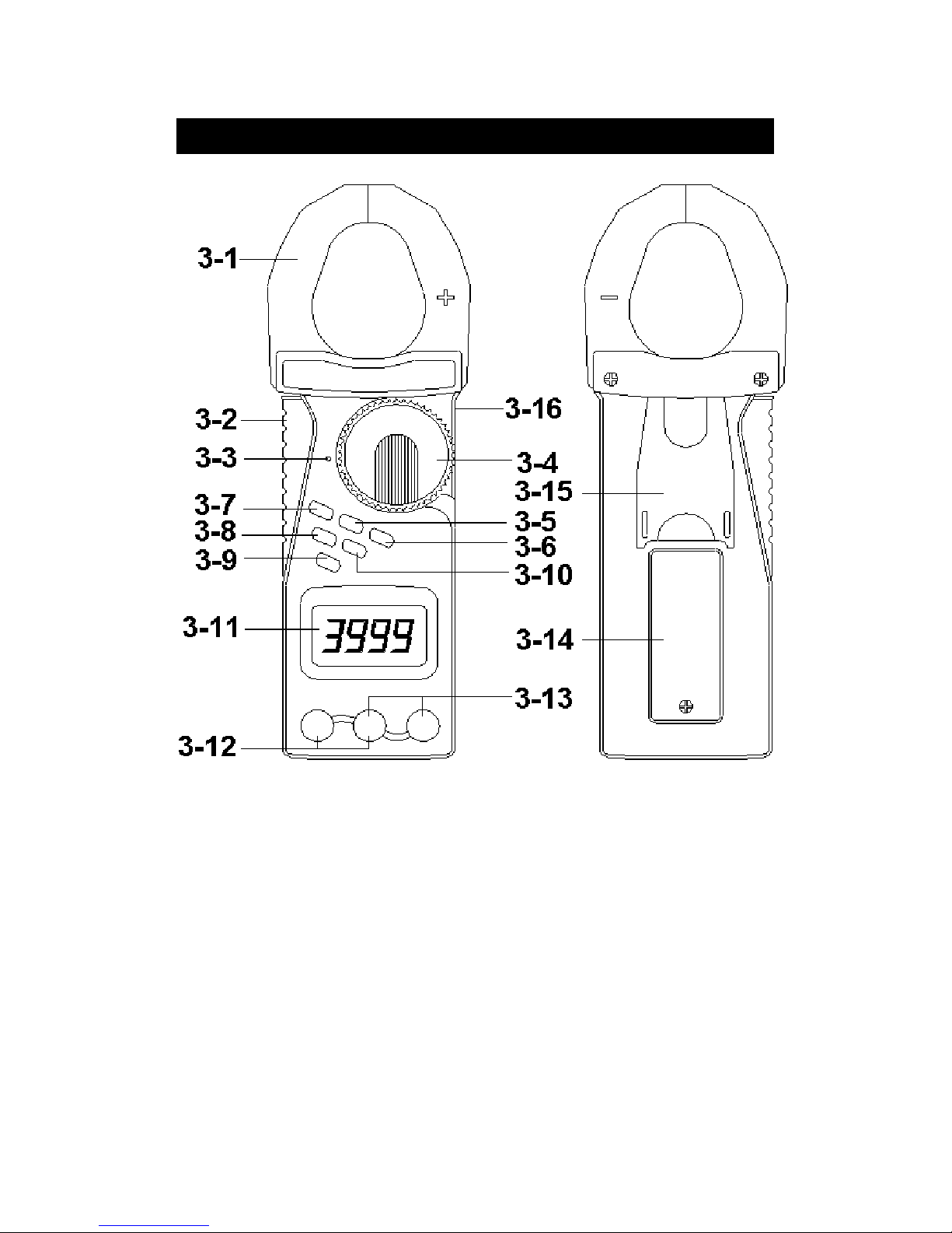
3. FRONT PANEL DESCRIPTION
Fig. 1
3-1 Current Sense Jaws 3-9 Function button ( DC/AC, ohm,
3-2
Trigg
er Continuity, Diode Capacitance )
3-3 Function indicator 3-10 Manual ran
g
e select button
3-4 Function rotary switch 3-11 Display
3-5 DCA zero button 3-12 uA/mA direct current input
3-6 Relative button terminals
3-7 Data hold / Back light 3-13 V, ohm, Hz, Diode, Continuity,
button Capacitance input terminals
3-8 V/Hz/% ( Duty Cycle ) 3-14 Battery cover/Compartment
button 3-15 Stand
3-16 RS-232 Output Terminal
4
Page 8

4. PRECAUTIONS & PREPARATIONS
FOR MEASUREMENT
1) Ensure that the DC 9V battery is connected to its snap
terminal with the right polarity and placed in the battery
compartment correctly.
2) Place the Red & Black Test Leads into the proper input
terminal before making measurement.
3) Remove either of the test leads from the circuit when
changing the measurement range.
4) Except operate the " Data Hold " function, it should
cancel the " Data Hold " function, otherwise the display
reading will freeze permanently.
5) Do not exceed the maximum rated voltage to the input
terminal.
6) Always switching the " Function Rotary Switch " to the
" Off " position when the instrument is not operation.
7) Remove the battery if the instrument is not to be used in
a long period of time.
8) Though the " Ohm " & " Capacitance " ranges build the
overload protection circuit, however it is prohibited to
apply any voltage to input terminal when making the
measurement.
9) The water resistance structure is apply for the
front panel only. Do not throw the instrument into
water, otherwise the meter will be damaged
permanently.
10)For safety consideration, when change the new test
leads, it should use the replace test leads that already
approval of " CATIII-1000V ".
5
Page 9

5. MEASURING PROCEDURE
5-1 Symbols & units of display
Symbols / Descriptions
Units
Appears when selecting DCV or DCA mode.
Appears when selecting ACV & ACA mode.
Appears when the " Data hold " function is
operated.
Appears when the " Relative " function is
operated.
Battery voltage is under the low condition
already.
Appears when operating the " Automatic
range " mode.
Appears when the " Continuity beeper " is
operated.
mV, V Units for voltage measurements.
Ω , KΩ , MΩ Units for resistance measurements
Appears when the " Diode " function is
operated.
Appears when measuring a DCV or DCA
value is negative.
% Unit for " Duty cycle " measurement.
uA, mA, A Units for " Current " measurement.
Hz, KHz Units for " Frequency " measurement.
nF, uF Units for " Capacitance " measurement.
RS-232 RS-232 data send out always.
6
Page 10

5-2 DCV, ACV Measurement
1) Connect BLACK test lead into " COM " terminal.
2) Connect RED test lead into " V " terminal.
3) If measure " DCV ", select the " Function rotary switch "
( 3-4, Fig. 1 ) to the " V " position then push the
" FUNC. button " ( 3-9, Fig. 1 ) for display show " ".
4) If measure " ACV ", select the " Function rotary switch "
( 3-4, Fig. 1 ) to the " V " position then push the
" FUNC. button " ( 3-9, Fig. 1 ) for display show " ".
5) When LCD show the " AUTO " marker, the meter is
under the " auto range " mode., the meter will select the
suitable measurement range automatically.
6) Under the operation of " auto range " mode, push the
" Range button " ( 3-10 Fig. 1 ) will hold the range.
5-3 Resistance Measurement
1) Connect BLACK test lead into " COM " terminal.
2) Connect RED test lead into " Ω " terminal.
3) Select the " Function rotary switch " ( 3-4, Fig. 1 ) to the
" Ω " position then push the " FUNC. button "
( 3-9, Fig. 1 ) for display show " Ω ".
4) When LCD show the " AUTO " marker, the meter is
under the " auto range " mode., the meter will select the
suitable measurement range automatically.
5) Under the operation of " auto range " mode, push the
" Range button " ( 3-10 Fig. 1 ) will hold the range.
5-4 Continuity Check
1) Connect BLACK test lead into " COM" terminal.
2) Connect RED test lead into " Ω " terminal.
3) Select the " Function rotary switch " ( 3-4, Fig. 1 ) to the
7
Page 11

" " position then push the " FUNC. button "
( 3-9, Fig. 1 ) for display show " ".
4) when the resistance value is less than 10 ohm, the beeper
sound will be generated.
5-5 Diode Test
1) Connect BLACK test lead into " COM " terminal.
2)
Connect RED test lead into " " terminal.
3) Select the " Function rotary switch " ( 3-4, Fig. 1 ) to the
" " position then push the " FUNC. button "
( 3-9, Fig. 1 ) for display show " ".
4) a. When connected with polarity as shown in Fig. 2, a
forward current flow is established and the approx.
Diode Forward Voltage (VF) value in volt will appears
on the display reading. If the diode under test is
defective, " .000 " or near " .000 " value ( short circuit ) or
" 1 " ( open circuit ) will be displayed.
Fig. 2 Fig. 3
b. When connected as shown in Fig. 3, a reverse check on
the diode is made. If the diode under test is good, " 1 "
will be displayed. If the diode under test is defective,
" .000 " or other numbers will be displayed. Proper diode
testing should include both steps a. and b. above.
8
Page 12

5-6 AC Current Measurement ( Clamp on )
1) Select the " Function rotary switch " ( 3-4, Fig. 1 ) to the
" 2000A " position then push the " FUNC. button "
( 3-9, Fig. 1 ) for display show " ".
2)
Press the " Trigger " ( 3-2, fig. 1 ) to open the " Current
Sensor Jaws " ( 3-1, Fig. 1 ) & clamp on the
measure conductor only.
Consideration :
a.
Recommend use the "auto range "mode typically.
However if push the " Range button " ( 3-10, Fig. 1 )
will hold the range.
b.
For safety reason, please insert the " Terminal rubber
cover " ( Fig. 4 ) for protection.
Fig. 4
5-7 DC Current Measurement ( Clamp on )
1) Select the " Function rotary switch " ( 3-4, Fig. 1 ) to the
" 2000A " position then push the " FUNC. button "
( 3-9, Fig. 1 ) for display show " ".
2) Push the " DCA zero button " ( 3-5, Fig. 1 ) at least 2
seconds to let the display show " ZERO " value.
3) Press the " Trigger " ( 3-2, fig. 1 ) to open the " Current
Sensor Jaws " ( 3-1, Fig. 1 ) & clamp on the
measure conductor only.
Consideration :
a.
Recommend use the "auto range "mode typically.
However if push the " Range button " ( 3-10, Fig. 1 )
will hold the range.
b.
For safety reason, please insert the " Terminal rubber
cover " ( Fig. 4 ) for protection.
9
Page 13

5-8 AC Current measurement (Direct input)
1) Connect BLACK test lead into " COM " terminal.
2) Connect RED test lead into " uA, mA " terminal.
3) If measure " uA " ( 400 uA, 4000 uA ), select the
" Function rotary switch " ( 3-4, Fig. 1 ) to the " uA "
position then push the " FUNC. button " ( 3-9, Fig. 1 )
for display show " ".
4)
If measure " mA " ( 40 mA, 400 mA ), select the
" Function rotary switch " ( 3-4, Fig. 1 ) to the " mA "
position then push the " FUNC. button " ( 3-9, Fig. 1 )
for display show " ".
5)
Open the circuit in which the current are to be measured.
Now securely connect test lead in series with the circuit.
5-9 DC Current measurement (Direct input)
All the measuring procedures are same as above 5-8,
except push the " FUNC. button " ( 3-9, Fig. 1 ) for
display show " ".
Consideration :
a. The max. reading value for direct input current
value is AC/DC 400 mA . Do not exceed the input
current value more than 400 mA. Otherwise the
protection fuse will be broken.
b. For the direct current input, after input the current,
the meter is out of function ( show 0 ). Then please
check if the protection fuse ( 500 mA ) is already
broken or not ? Detail please refer " 6-2 Replacement
of fuse ".
10
Page 14

5-10 Capacitance Measurement
1)
Connect BLACK test lead into " COM " terminal.
2)
Connect RED test lead into " " terminal.
3)
Select the " Function rotary switch " ( 3-4, Fig. 1 ) to the
" " position then push the " Function button " ( 3-9,
Fig. 1 ) for display show " nF "
4)
Zero adjustment :
Due to the consideration of the existing " stray
capacitance " of the internal circuit board or the test
aliigator. For the 50 nF & 500 nF range, it should to
make the zero adjustment procedures before make the
measurement first. Open the input terminal & not
connecting the measured capacitor, push the " REL.
Button " ( 3-6, Fig. 1 ), the display will show zero value.
Then connect the measuring capacitor again & make the
measurement following.
5) For the capacitance measurement, the meter is always
under the " auto range " mode., it will select the suitable
measurement range automatically.
5-11 Frequency Measurement
1) Connect BLACK test lead into " COM " terminal.
2) Connect RED test lead into " Hz " terminal.
3) Select the " Function rotary switch " ( 3-4, Fig. 1 ) to the
" Hz " position then push the " Hz/% button " ( 3-8,
Fig. 1 ) for display show " Hz " .
4) For the FREQUENCY measurement, the meter is always
under the " auto range " mode, it will select the suitable
measurement range automatically.
11
Page 15

5-12 Duty Cycle Measurement
All the measuring procedures are same as above 5-11
( Frequency measurement ) except push the " Hz/% "
( 3-8, Fig. 1 ) for display show " % ".
5-13 Data Hold Operation
1) During the measurement, pushing the " Hold button "
( 3-7, Fig. 1 ) once a while will freeze the measured value
& the LCD will indicate " H " symbol.
2) Push the " Hold Button " again to release the data hold
function.
5-14 Relative Operation
1) During the measurement, the circuit will memorize the
last measured values if push the " REL. Button " ( 3-6,
Fig. 1 ) at once, then LCD will show zero value & a " REL "
indicator.
2) The input measured values will deduct last measured
values " automatically, then show those new value on the
display.
3) It will release the Relative Measurement function if push
the REL. button at once again, at same time the " REL "
marker will disappear.
5-15 Back light Operation
1)
Push the " button " ( 3-7, Fig. 1 ) about two
seconds continuously, the LCD back light lamp will turn
on.
12
Page 16

6. MAINTENANCE
6-1 Replacement of Battery
Caution :
Remove test leads before
open the battery cover !
1)
When the LCD display shows " ". It is necessary to
replace the battery, However in-spec. measurement may
still be made for several hours after " Low battery
indicator " appears before the instrument become
inaccurate.
2) Open the screw of " Battery Cover " ( 3-14, Fig. 1 ) by
screwdriver, then move the battery.
3) Replace with 9V battery and reinstate the cover.
6-2 Replacement of Fuse
Fuse :
Rating : 500 mA, Size : 5 mm dia. x 20 mm
1) The meter is provided with one 5 x 20 mm 500 mA fuse
for current ( direct input ) measurement. current range
overload protection purpose.
2) When the direct input current range can not operate, please
check if the fuse is broken ?
When replace the fuse, open the housing case and
remove the fuse from the main PC board.
3) Replace the fuse according the spec. and reinstate the
housing case again.
13
Page 17

6-3 Cleaning
Caution :
Cleaning - Only use
the dry cloth to clean
the plastic case !
7. RS232 PC SERIAL INTERFACE
The instrument has RS232 PC serial interface via a 3.5
mm terminal ( 3-16, Fig. 1 ).
The data output is a 16 digit stream which can be
utilized for user's specific application.
A RS232 lead with the following connection will be
required to link the instrument with the PC serial port.
Meter PC
(9W 'D" Connector)
Center Pin..........................Pin 4
(3.5 mm jack plug)
Ground/shield......................
.
Pin 2
2.2 K
resister
Pin 5
The 16 digits data stream will be displayed in the
following format :
D15 D14 D13 D12 D11 D10 D9 D8 D7 D6 D5 D4 D3 D2 D1 D0
14
Page 18

Each digit indicates the following status :
D15 Start Word
D14 4
D13 1
D12, D11 Annunciator for Display
M ohm = 40 AC mV = 49 DC mV = 18
K ohm = 39 AC V = 50 DC V = 34
ohm = 38 AC A = 52 DC A = 36
KHz = 33 Hz = 31 % = 03
DCuA = 35 DCmA = 37 Diode = 34
ACuA = 51 ACmA = 53 uF = 44
nF = 43
D10 Polarity
0 = Positive 1 = Negative
D9 Decimal Point(DP), position from right to
the left
0 = No DP, 1= 1 DP, 2 = 2 DP, 3 =3 DP
D8 to D1 Display reading, D1 = LSD, D8 = MSD
For example :
If the display reading is 1234, then D8
to D1 is : 00001234
D0 End Word
RS232 FORMAT : 9600, N, 8, 1
Baud rate 9600
Parity No parity
Data bit no. 8 Data bits
Stop bit 1 Stop bit
15
Page 19

8. OPTIONAL ACCESSORIES AND
ADAPTERS
RS232 cable * Computer interface cable.
UPCB-02 * Used to connect the meter to
the computer ( COM port ).
USB cable * Computer interface cable.
USB-01 * Used to connect the meter to
the computer ( USB port ).
Data * The SW-U801-WIN is a multi
Acquisition displays ( 1/2/4/6/8 displays )
software powerful application software,
SW-U801-WIN provides the functions of data
logging system, text display,
angular display, chart display,
data recorder high/low limit, data
query, text report, chart report..
.xxx.mdb data file can be
retrieved for EXCEL, ACESS..,
wide intelligent applications.
Light Adapter Model : LX-02
EMF Adapter Model : EMF-824
Pressure Model : PS-403
Adapter
Anemometer Model :AM-402
Adapter
Tachometer Model :TA-601
Adapter
Sound Adapter Model : SL-406
High Voltage Model : HV-40
Probe
Test lead with Model : TL-02AS
alligator clips
Soft Model : CA-05A
Carry case
16
Page 20

9. THE ADDRESS OF AFTER
SERVICE CENTER
17
0908-CM9930R
 Loading...