

Page 1
1,600 point data logger, RS232, AC/DC adapter
2,000 uS 20 mS, 100 mS, auto range, auto calibration
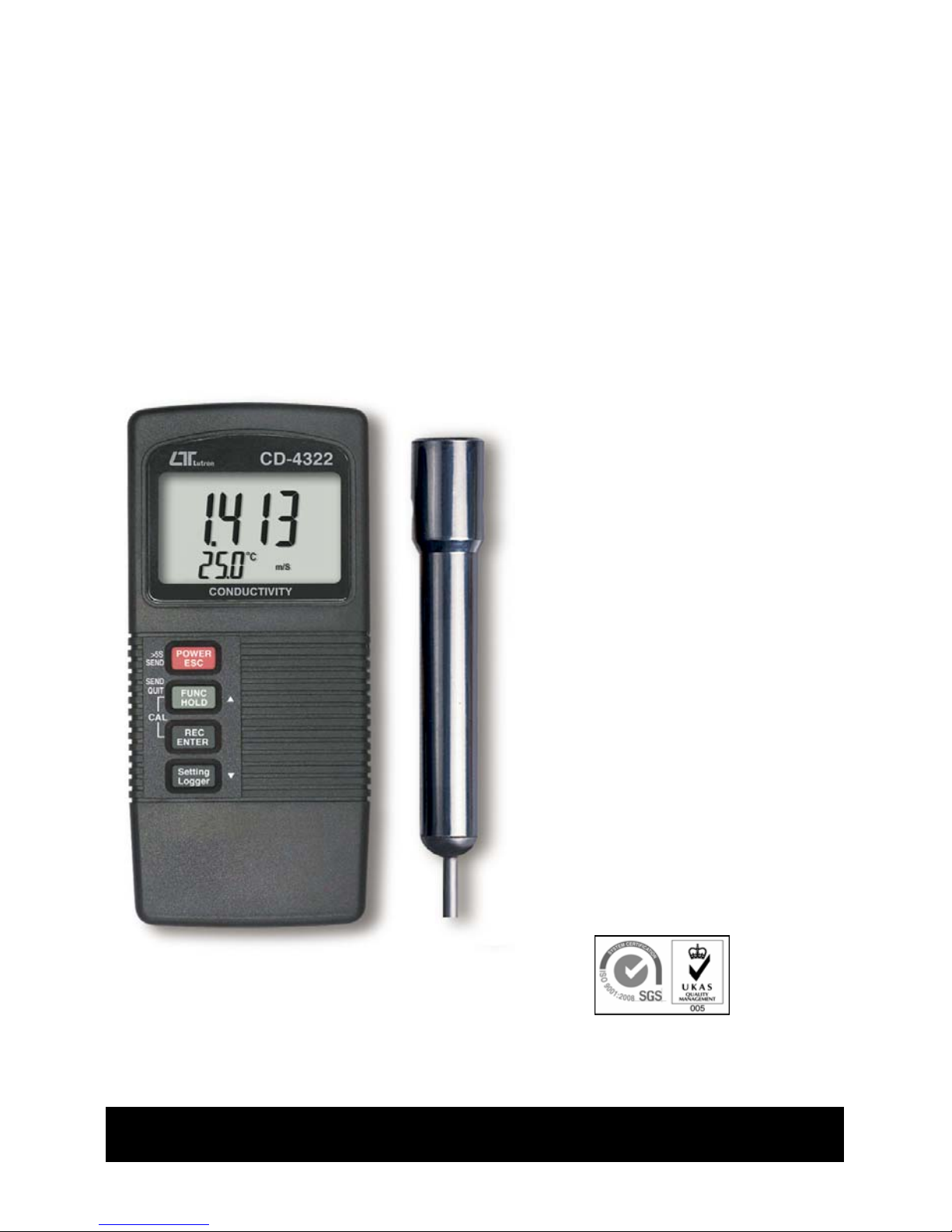
CONDUCTIVITY
METER
Model : CD-4322
Your purchase of this
CONDUCTIVITY METER
marks a step forward for
you into the field of
precision measurement.
Although this METER is
a complex and delicate
instrument, its durable
structure will allow
many years of use if
proper operating
techniques are
developed. Please read
the following
instructions carefully
and always keep this
manual within easy
reach.
OPERATION MANUAL
Page 2

TABLE OF CONTENTS
1. FEATURES....................................................................... 1
2. SPECIFICATIONS............................................................. 2
3. FRONT PANEL DESCRIPTION...........................................
.
4
3-1 Display...................................................................... 4
3-2 Power/ESC/Send button.............................................
.
4
3-3 FUNC/HOLD button ( Send quit/ button ).................
.
▲ 4
3-4 REC/Enter button....................................................... 4
3-5 Settin
g
/Logger button ( button ).............................▼ 4
3-6 Probe input socket.....................................................
.
4
3-7 DC 9V adapter socket.................................................4
3-8 RS-232 output terminal..............................................
.
4
3-9 Battery compartment/Cover........................................4
3-10 Battery cover screws................................................
.
4
3-11 Probe Handle........................................................... 4
3-12 Sensin
g
Electrode.....................................................4
3-13 Probe Plu
g
............................................................... 4
4. MEASURING PROCEDURE.................................................6
4-1 Conductivity Measurement..........................................6
4-2 TDS Measurement......................................................6
4-3 Data Hold..................................................................7
4-4 Data Record ( Max., Min. readin
g
)..............................7
4-5 Data Lo
gg
er...............................................................8
5. ADVANCED ADJUSTMENT PROCEDURE.............................10
5-1 Temp. compensation factor settin
g
..............................11
5-2 Chan
g
e the Temp , unit......................................℃℉ 11
5-3 Auto power ON/OFF...................................................12
5-4 Chan
g
e the data logger sampling time.........................12
5-5 To show the balance data numbers in the memory......
.
12
5-6 Clear the existin
g
saving data from the memory...........13
5-7 Code enterin
g
for the further calibration usage.............13
6. SEND THE DATA OUT FROM THE METER.......................... 13
7. RS232 PC SERIAL INTERFACE..........................................
.
15
8. BATTERY REPLACEMENT..................................................17
9. CALIBRATION..................................................................17
10. OPTIONAL ACCESSORIES...............................................19
Page 3

1. FEATURES
* * 3 measurement range, 2,000 uS, 20 mS, 100 mS with
auto range.
* Function : Conductivity, TDS.
* Separate probe, easy for operation of different
measurement environment.
* Automatic temperature compensation range : 0 to 50 .℃
* Carbon rod electrode for long life.
* Innovative feature with built-in automatic temperature
compensation factor adjustable between 0 to 5.0% per .℃
* Selecting " 0% per " of Temp. Coefficient Adjust,℃
allows you to take uncompensated conductivity
readings ( absolute conductivity measurement ).
* Microprocessor circuit assures high accuracy and provides
special functions and features.
* Multi-display, show Conductivity and Temp. value at the
same time.
* Data hold function for freezing the desired value.
* Records max. and min. value with recall.
* Build in temperature , measurement with default.℃℉
* Manual and auto data logger, with flexible sampling
time selection, can save max. 1,600 reading data.
* Power function can default to auto off or manual off.
* Build in the input socket for DC 9V power adapter.
* Use the durable, long-lasting components, including a
heavy duty & compact ABS-plastic housing case.
* RS232/USB PC serial interface.
* Applications for Aquarium, Medical research, Agriculture,
Fish hatcheries, Laboratory, Water conditioning, Mining
industry, Schools & Colleges, Quality control...
industry, quality control, school & college, water
conditioning.
1
Page 4
2. SPECIFICATIONS
Display LCD size : 44 mm x 29 mm.
Dual function LCD
Circuit Custom one-chip of microprocessor LSI
circuit.
Function : Conductivity, TDS.
Ranges and
Conductivity range :
Resolution 2000 uS/20.00 mS/100 mS.
Conductivity resolution :
* three ran
ges
1 uS/0.01 mS/0.1 mS.
* auto ran
ge
T
DS range :
1200 ppm/12,000 ppm/66,000 ppm.
T
DS resolution :
1 ppm/10 ppm/100 ppm.
Accuracy ± ( 2% FS + 1 d )
* 23 ± 5
℃
* FS : full scal
e
Temperature Automatic from 0 to 50 (32 - 122 ),℃℉
Compensation with temperature compensation factor
variable between 0 to 5.0% per C.
Conductivity Carbon rod electrode for long life.
Probe
Structure
Memory Records Maximum, Minimum readings with
Recall recall.
Power of
f
Auto power off saves battery life, or manual
off by push button.
* Auto power off :
Power will off automatically after 10 min., if no button
be pressed.
Data Output RS 232 PC serial interface.
Sampling Time Manual Push the data logger button once
of Data Logger will save data one time.
* Set sampling time to 0 second.
Auto 1, 2, 5, 10, 30, 60, 600, 1800,
3600 seconds.
Data Logger Max. 1,600-point Data logger
number
2
Page 5
Data Hold Freeze the display reading.
Sampling Time Approx. 1 second.
of display
Data Output RS 232/USB PC serial interface.
* Connect the optional RS232 cable
UPCB-02 will get the RS232 plug.
* Connect the optional USB cable
USB-01 will get the USB plug.
Operating 0 to 50 .℃
Temperature
Operating Less than 80% RH.
Humidity
Power Supply 006P DC 9V battery ( Alkaline or Heavy duty
type ) or DC 9V adapter input.
* AC/DC power adapter is optional.
Power Current Approx. DC 5.7 mA.
Weight 295 g/0.65 LB.
* Include probe and batterry.
Dimension
Main instrument :
135 x 60 x 33 mm.
Conductivity Probe :
Round, 22 mm Dia. x 120 mm length.
Accessories Conductivity probe..........................1 PC.
Included Operation manual...........................1 PC.
Optional * 1.413 mS Conductivity Standard
Accessories Solution..............................
.
CD-14
* RS232 cable........................UPCB-02
* USB cable...........................
.
USB-01
* Data Acquisition software.....SW-U801-WIN
* Data lo
gg
er software............SW-DL2005
* Hard carryin
g
case...............CA-06
* Soft carryin
g
case................CA-05A
* AC to DC 9V adapter
3
Page 6
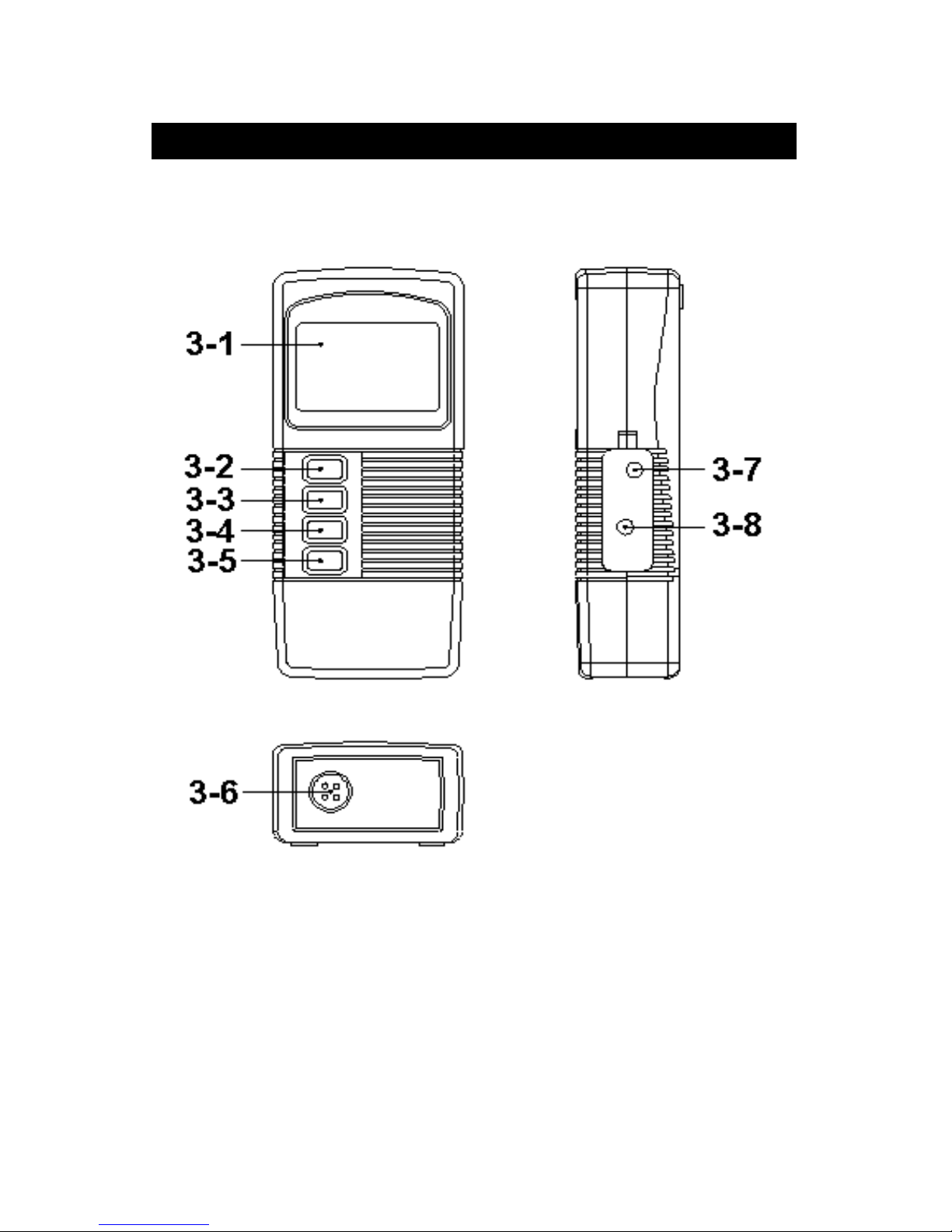
3. FRONT PANEL DESCRIPTION
Fig. 1
4
Page 7
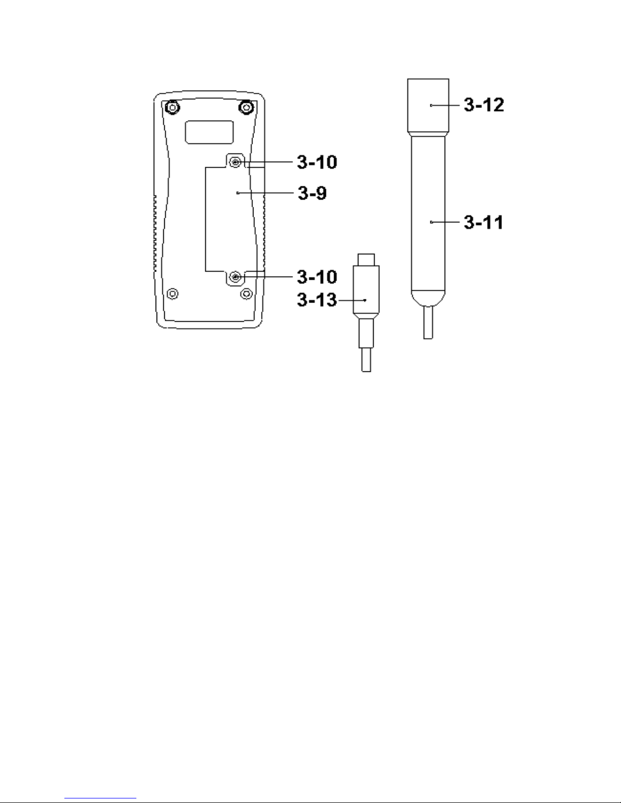
Fig. 2
Fig. 2
3-1 Display
3-2 Power/ESC/Send button
3-3 FUNC/Hold button ( Send quit/ button )▲
3-4 REC/Enter button
3-5 Setting/Logger button ( button )▼
3-6 Probe input socket
3-7 DC 9V adapter socket
3-8 RS-232 output terminal
3-9 Battery compartment/Cover
3-10 Battery cover screws
3-11 Probe Handle
3-12 Sensing Electrode
3-13 Probe Plug
5
Page 8

4. MEASURING PROCEDURE
4-1 Conductivity measurement
1)Turn on the meter by pressing the " Power Button "
( 3-2, Fig. 1 ) momentarily.
* Press the " Power Button " ( 3-2, Fig. 1 )
momentarily again will turn off the meter.
Connect the " Probe Plug " ( 3-13, Fig. 2 ) into the
" Probe input socket " ( 3-6, Fig. 1 ).
The " Display " ( 3-1, Fig. 1 ) will show the unit as :
0
xx,x ℃ uS
Now the meter is ready for the conductivity measurement.
2)Hold the " Probe Handle " ( 3-11, Fig. 2 ) by hand and
immerse the " Sensing Electrode " ( 3-12, Fig. 2 )
immersed wholly into the measured solution. Shake the "
Sensing Electrode " to let the electrode's internal air
bubble drift out from the sensing Electrode.
" Display " ( 3-1, Fig, 1 ) will show the conductivity
mS ( uS ) values, at the same time the left bottom
display will show the Temp. value of the measured
solution.
*The method to change the Temp. unit from
" " to " " or " " to " ", please refer to :℃℉℉℃
Chapter 5-2 Change the Temp , unit, page 11.℃℉
6
Page 9

When make the
measurement should
immerse the " Sensing
Electrode " immersed
wholly into the measured
solution.
4-2 TDS measurement
1)During the above 4-1 Conductivity measurement, if
press the " Hold button " ( 3-3, Fig. 1 ) continuously at
least two seconds will enter into the function of TDS
measurement with default, the display will show as :
0
xx,x ℃ PPM
Other TDS measurement procedures are similar as Conductivity
measurement
2)During the TDS measurement, if press the " Hold
button " ( 3-3, Fig. 1 ) continuously at least two
seconds again will enter into the function of
Conductivity measurement with default, refer
section 4-1.
7
Page 10

4-3 Data Hold
During the measurement, press the " Hold button " ( 3-3,
Fig. 1 ) once will hold the measured value & the LCD will
display a " HOLD " symbol.
* Press the " Hold button " once again will release the
data hold function.
4-4 Data Record ( Max., Min. reading )
* The data record function records the maximum and
minimum readings. Press the " REC button " ( 3-4, Fig. 1
) once to start the Data Record function and there
will be a " REC " symbol on the display.
* With the " REC " symbol on the display :
a)Press the " REC button " ( 3-4, Fig. 1 ) once, the
" REC MAX " symbol along with the maximum value
will appear on the display.
If intend to delete the maximum value, press the
" Hold button " ( 3-3, Fig. 1 ) once, the display will
show the " REC " symbol only & execute the
memory function continuously.
b)Press the " REC button " ( 3-4, Fig. 1 ) again, the
" REC MIN. " symbol along with the minimum value
will appear on the display.
If intend to delete the minimum value, press the
" Hold button " ( 3-3, Fig. 1 ) once, then the display
will show the " REC " symbol only & execute the
memory function continuously.
c)To exit the memory record function, just press the
" REC " button for 2 seconds at least. The display will
revert to the current reading.
4-5 Data Logger
The data logger function can save 1,600-point measuring
data.
8
Page 11

The data logger procedures are following :
a)Press the " REC button " ( 3-4, Fig. 1 ) once to start
the Data record function and there will be a " REC "
symbol on the display.
b)Auto Data Logger ( Sampling time should select
to 1, 2, 5, 10, 30, 60, 600, 1800 or 3600 seconds )
Press the " Logger button " ( 3-5, Fig. 1 ) once to start
the Data Logger function. The " REC " symbol will flash
per 1.5 second and the beeper will sound when save
the data into the memory. Now the Data Logger
function is executed.
Manual Data Logger ( Sampling time should set
to 0 second )
Press the " Logger button " ( 3-5, Fig. 1 ) once will
save the data one time into the memory, at the
same time the symbol " REC " will flash once and
the beeper will sound.
Memory full
When execute the data logger function, if the upper
display show " FULL " with flashing, it indicate the
memory data already over 1,600 no. and the
memory is full.
c)During the Data Logger function is executed, press the
" Logger button " ( 3-5, Fig. 1 ) once will stop the
data logger function, the " REC " symbol will stop to
flash.
If press the " Logger button " ( 3-5, Fig. 1 ) once again
will continuous the Data Logger function.
Note :
1) If intend to change the data logger sampling time, please
refer to chapter 5-4, page 12.
2) If intend to know the space of balance data numbers into the
memory IC, please refer to chapter 5-5, page 12.
3) If intend to clear the saving data from the memory please
refer section 5-6, page 13.
9
Page 12

5. ADVANCED SETTING PROCEDURES
Before executing Advanced Setting Procedures,
exit the " Hold function " and the " Record "
function first.
* Press " Setting button " continuously at
least 5 seconds to enter the setting function.
* After already set the desiring value ( function ),
press the " Enter button " to save with default.
* Press the " Esc button " to escape the setting
procedures.
a.Hold the " Setting button " ( 3-5, Fig. 1 ) at least five
seconds will enter the Advanced Setting Procedures.
b.One by one to press the " Setting button " ( 3-5, Fig. 1 )
once a while to select the main setting function in
sequence and show on the text the lower display as :
SEt.......
.
Temp. Compensation Factor Default Setting.
.........
.
℃ Change the Temp , unit℃℉
OFF......
.
Auto power ON/OFF management
SP-t......Change the data logger sampling time
SPACE..
.
To show the balance data numbers in the memory
CLr.......
.
Clear the existing saving data from the memory
Code.....Code entering for the further calibration usage
10
Page 13

5-1 Temp. compensation factor Setting.
( Lower display show " SEt " )
After the low display show " SEt ", press the " Enter
button " ( 3-4, Fig. 1 ) once. the " SEt " symbol will flash,
the up display will show the " Temp. compensation
factor ".
Use " button " ( 3-3, Fig. 1 ) and " button " ( 3-5,▲▼
Fig. 1 ) to adjust the up display value until it same as
the desiring Temp. Compensation Factor value ( unit is
% per ) exactly.℃
After select the desiring value, press the " Enter button "
( 3-4, Fig. 1 ) to save the data.
Remark :
* The " Temp. Compensation Factor " only can adjust
from 0.00 to 5.00 % per .℃
* After power off and on again, the original setting
value will be cleared and return to 2.00 % per ℃
( default value ).
5-2 Change the Temp , unit℃℉
( Lower display show " " )℃
a. Use " button " ( 3-3, Fig. 1 ) to select " " or " ".▲℃℉
b.After select the desiring value ( or ), press the ℃℉
" Enter button " ( 3-4, Fig. 1 ) to save the data with
default.
11
Page 14

5-3 Auto power On/Off
( Lower display show " OFF " )
a.Use " button " ( 3-3, Fig. 1 ) to select " YES " or " no ".▲
* YES : Auto power off.
* no : Auto power disable, it is the manual power off.
b.After select the desiring function ( YES or no ), press the
" Enter button " ( 3-4, Fig. 1 ) to save the function with
default.
5-4 Change the data logger sampling time
( Lower display show " SP-t " )
a.Use " button " ( 3-3, Fig. 1 ) to select ▲
data logger sampling time to
0, 1, 2, 5, 10, 30, 60, 600, 1800, 3600 seconds
b.After the sampling time value is determined, press the
Enter button " ( 3-4, Fig. 1 ) to save the sampling
time with default.
Note :
Set the sampling time to 0 second is used
for the manual Data Logger function.
5-5 To show the balance data numbers in the
memory
( Lower display show " SPACE " )
The display will show the balance data no. that exist
into the memory ( allow memorize data no. ).
12
Page 15

5-6 Clear the existing saving data from the memory
( Lower display show " CLr " )
a.Use " button " ( 3-3, Fig. 1 ) to select " YES " or " no ".▲
* YES : It will execute the memory clear function..
* no : It will be not to clear the memory.
b.If select " YES ", press the " Enter button " ( 3-4, Fig. 1 )
the beeper will sound three sounds for warning,
if really intend to clear the memory, then press the
" Enter button " again.
5-7 Code entering for the further calibration usage
( Lower display show " CodE" )
The upper display will show 0.
The code setting is used for the further technician
service usage, it do not enter any new code, just press
the " Enter button " ( 3-4, Fig. 1 ) will finish the
Advanced Setting Procedure.
6. SEND THE DATA OUT
1)To send the data out from the meter, exit the
" Hold function " and the " Record function " at first.
2)Press the " Send button " ( 3-2, Fig. 1 ) at least 5
seconds until the lower display show " r232 ", then
release the button.
108 The total data logger
no. that saved into
r232 the memory.
13
Page 16

3)Push the " Send button " ( 3-2, Fig. 1 ) once, the lower
display will show " SEnd ", the upper no. will count up
until reach the data logger storage no., at the same
the storage data logger data will send out the meter
from the " RS-232 output terminal " ( 3-8, Fig. 1 ).
0 Count up from 0 to
the data logger
SEnd storage no.
4)If intend up load the data to the computer, then
should connect the optional RS232
cable/UPCB-01 or USB cable/USB-01 and
cooperate the Data Logger software ( optional,
Model : SW-DL2005 ).
5)Press the " Send quit button " ( 3-3, Fig. 1 ) will
escape the data sending function.
14
Page 17

7. RS232 PC SERIAL INTERFACE
The instrument has RS232 PC serial interface via a 3.5
mm terminal ( 3-8, Fig. 1 ).
The data output is a 16 digit stream which can be
utilized for user's specific application.
A RS232 lead with the following connection will be
required to link the instrument with the PC serial port.
Meter PC
(3.5 mm jack plug) (9W 'D" Connector)
Center Pin...............................Pin 4
Ground/shield........................
.
Pin 2
Pin 5
The 16 digits data stream will be displayed in the
following format :
D15 D14 D13 D12 D11 D10 D9 D8 D7 D6 D5 D4 D3 D2 D1 D0
15
Page 18

Each digit indicates the following status :
D15 Start Word
D14 4
D13 When send the upper display data = 1
When send the lower display data = 2
D12 & D11 Annunciator for Display
= 01 ℃ = 02℉
uS = 13 mS = 14
D10 Polarity
0 = Positive 1 = Negative
D9 Decimal Point(DP), position from right to
the left
0 = No DP, 1= 1 DP, 2 = 2 DP, 3 = 3 DP
D8 to D1 Display reading, D8 = MSD, D1 = LSD.
For example :
If the display reading is 1234, then D8 to
D1 is : 00001234
D0 End Word
RS232 setting
Baud rate 9600
Parity No parity
Data bit no. 8 Data bits
Stop bit 1 Stop bit
16
Page 19

8. BATTERY REPLACEMENT
1)
When the upper left corner of LCD display show " ",
it is necessary to replace the battery. However, in-spec.
measurement may still be made for several hours after
low battery indicator appears before the instrument
become inaccurate.
2)Open the " Battery Cover " ( 3-9, Fig. 2 ) away from
the instrument by loosing the " Battery cover screws "
( 3-10, Fig. 2 ) and remove the battery.
3)Replace with 9V battery ( Alkaline or Heavy duty type )
and reinstate the cover.
4)Make sure the battery cover is secured after changing
the battery.
9. CALIBRATION
1)Connect the " Probe Plug " ( 3-13, Fig. 1 ) into the
" Probe input socket " ( 3-6, Fig. 1 ).
Turn on the meter by pressing the " Power Button "
( 3-2, Fig. 1 ) momentarily.
2)Prepare a " Conductivity Standard Solution ", for
example the optional " 1.413 Conductivity Standard
Solution, CD-14 ".
3)Hold the " Probe Handle " ( 3-11, Fig. 2 ) by hand and
immerse the " Sensing Electrode " ( 3-12, Fig. 1 )
wholly into the " Standard solution ". Shake the "
Sensing Electrode " to let the electrode's internal air
bubble drift out from the sensing Electrode.
17
Page 20

4)a.Press the " Hold button " ( 3-3, Fig. 1 ) once, the
" Display " ( 3-1, Fig. 1 ) will show the " Hold "
indicator, then following press the " REC button "
( 3-4, Fig. 1 ) once, the Display will show :
CAL
YES
b.If intend to make the calibration, then press the
" Enter button " ( 3-4, Fig. 1 ) to confirm.
The Display will show as example :
1458
CAL uS
The upper value will show the measuring value
The lower display will show the text " CAL ", then
after a while the text " CAL " will be flashed.
c. During the text " CAL " is flashed, can use the buttons :
" button " ( 3-3, Fig. 1 )▲
" button " ( 3-5, Fig. 1 )▼
to adjust the upper display reading same as
the value of " Conductivity Standard Solution ", for
example 1413 uS for CD-14 standard solution.
1413 Standard solution
flashing CAL uS value
18
Page 21

5)After the upper display already adjust to the value
of " Conductivity Standard Solution ", release the
fingers from the buttons.
After a while the upper display will show the text
" SAVE " and " End " then return to normal display.
The calibration procedures are finished, the calibration
value will save into the memory circuit.
10. OPTIONAL ACCESSORIES
Carrying case Hard carrying case.
CA-06 ( 280 x 195 x 65 mm )
Carrying case Soft carrying case with sash
CA-05A ( 260 x 110 x 55 mm )
19
Page 22

1.413 mS
Conductivity
Standard Solution
CD-14
RS232 cable * Isolated RS232 cable.
UPCB-02 * Used to connect the meter to
the computer
RS232 cable * USB Computer interface cable.
USB-01 * Isolated USB cable.
Data Logger * Software the used to download
software the data logger ( data recorder )
SW-DL2005 from the meter to computer.
Data Acquisition * The SW-U801-WIN is a multi
software displays ( 1/2/4/6/8 displays )
SW-U801-WIN powerful application software,
provides the functions of data
logging system, text display,
angular display, chart display,
data recorder high/low limit, data
query, text report, chart report..
.xxx.mdb data file can be
retrieved for EXCEL, ACESS..,
wide intelligent applications.
Power adapter AC 110V to DC 9V, USA plug.
AC 220V/230V to DC 9V.
Germany plug.
20
0712-CD4322
 Loading...