

Page 1
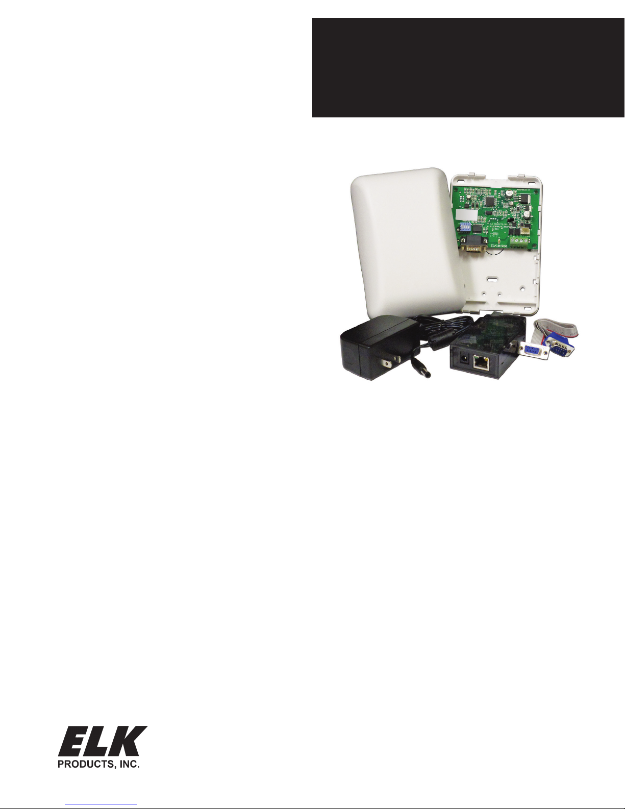
ELK-M1XSLC
M1 Interface kit for Lutron
CASÉTA® WIRELESS
Homeworks QS or Caséta Line
APPLICATION:
The ELK-M1XSLC Interface Kit has been enhanced
to support Lutron's Homeworks and Caséta products.
Interfacing M1 Control to Lutron allows intelligent control
of devices in response to security system actions or
conditions. The most typical integration devices supported
are:Lights, Shades, and Keypad controllers. The level
of integration is dependent on which type and model of
Lutron devices being implemented.
ELK-M1XSLU SPECIFICATIONS:
• Connects to the ELK-M1 Keypad Databus
• Addressable as a TYPE 5 Databus (ID 1-7)
• Operating Voltage: 12 Volts DC Supplied from M1
• Current Draw: 31mA
• Activity/Status LED (Orange)
• Auto-Reset Hardware Watchdog Circuit
• Housing Dimensions: 4.25" x 6.375" x 2.125"
• Circuit Board: 2.75" x 3.95"
• Connects to IP232 via RS232 and null modem (Incl.)
• Connects to M1 via 4 screw terminals
INSTRUCTIONS
ELK-IP232 SPECIFICATIONS:
• Converts RS232 Serial to IP for connection to the IP
port on Lutron's QS or Smartbridge Pro Interfaces
• LED Indicators for Power, Link, and Data
• Operating Voltage: 12 Volts D.C.
Supplied from ELK-P1216 Power Supply (Incl)
• Current Draw: 135 mA
• Dimensions: 3.85” L x 1.7” W x 0.93” D
2017 Elk Products Inc. All rights reserved.
Lutron, Homeworks, QS, Caséta Wireless, and Smartbridge Pro are
registered trademarks of Lutron Electronics Co., Inc.
PO Box 100
3266 US Hwy 70 West
Hildebran, NC 28637
828-397-4200 828-397-4415 Fax
http://www.elkproducts.com
L659 Rev. B 1/25/2016 Printed in USA
Specications are Subject to Change without notice.
NOTICE: Drawings, illustrations, diagrams, part numbers, etc. are provided as reference only and are based on equipment available at the time
the information was created. All information contained in this document
are subject to change without notice.
The extent of integration between Elk Products and Partner Mfgs varies,
and there may be situations or limitations beyond Elk's control that make
certain desirable features unavailable or unusable. Partner products and/
or protocols, including Elk's may not contain the capabilities or data denitions to permit additional integration beyond what is currently available.
Partners may also, at their option, add, modify, or discontinue features or
support without notication.
NOTE: The Caséta product family offers temperature solutions using "WiFi
thermostats". These are not supported through M1. They can only be
controlled through IP using Lutron Caséta smartphone app.
For reasons stated herein, Elk Products makes no warranty that it will
be able to integrate all available features or operations, nor does it make
any express or implied warranties of tness for a particular purpose or of
merchantability. Refer to Elk's Limited Warranty.
Page 2

PLEASE READ THIS PAGE FIRST!
LUTRON CASÉTA® WIRELESS
Lutron Caséta® Wireless
The following components will be needed to integrate Elk to Lutron Caséta Wireless.
QTY Part Number & Description
1 ELK-M1 or M1EZ8 Control
1 ELK-M1XSLC Kit
Contents of kit:
ELK-M1XSLU M1 to Lutron serial interface
ELK-IP232 Serial to IP Converter (Firmware version 1.0.18 and later ***)
9 Pin Serial ribbon cable
9 Pin Null Modem adapter
ELK-P1216 Plug-in 12VDC Power Supply
1 ELKRP Remote Programming Software. This can be downloaded from Elk Website www.elkproducts.com
1 ELK-IP232 Utility Software. This can be downloaded from Elk Website www.elkproducts.com
1 Lutron Smartbridge Pro Interface w/plug-in Power Pack
? 1 or more Lutron Caséta Wireless lighting or shade devices
Overview: Lutron Caséta devices communicate wirelessly with each other through a central interface called the Lutron Smartbridge.
This Smartbridge is also an IP Gateway that connects to the customer's router and ultimately to Lutron's Caséta Cloud services. Lutron
supplies iOS and Android smartphone apps that connect to their cloud services and provides the means for operation and setup of
the devices. Integration of Caséta to the ELK control requires the special "PRO" version of the Smartbridge (Smartbridge Pro). The
ELK-M1XSLU Lutron Interface handles the protocol conversion from ELK to Lutron and the ELK-IP232 creates the IP connectivity
with the Lutron Smartbridge.
Disclaimer: While Caséta does integrate with temperature solutions like "WiFi Thermostats", these devices are linked directly to
the Caséta Cloud services and are only controllable via the smartphone app. They do not communicate through the Smartbridge Pro
and therefore do not communicate with ELK. Please be aware that Caséta integration with ELK does not provide any ability for Elk
to interface with "WiFi" Thermostats.
Integration Device Capacity: Caséta can host up to 50 total wireless devices. The devices that are currently known to interface
with ELK are the Caséta lighting dimmers/switches, Caséta plug-in dimmers, and Caséta Window Blinds/Shades.
Integration Scene Capacity: Caséta offers up to 50 total scenes. These scenes are setup via the smartphone apps and stored in
the Smartbridge. The M1 integration communicates to the Smartbridge Pro to trigger these scenes or "buttons: as they are referred
to in the Lutron integration report.
Important: Do not attempt to integrate with Lutron Homeworks using any of Elk's other "standard" serial interface modules. ONLY
the ELK-M1XSLC Kit provides the hardware and software for near plug-and-play integration with Lutron Homeworks.
Page 2
M1XSLC Installation Manual - LUTRON CASÉTA WIRELESS
Page 3
LUTRON CASÉTA WIRELESS
TABLE 2: Diagnostic LED Indicator
Slow blink (1/2 sec.) = Normal communication with M1.
Rapid flicker = Discovery Mode. The M1XSLU is synchronizing to collect current lighting data. This is automatically
performed upon reboot or power up.
No blink = No communication with M1. Check the wiring with the M1 and that the device has power.
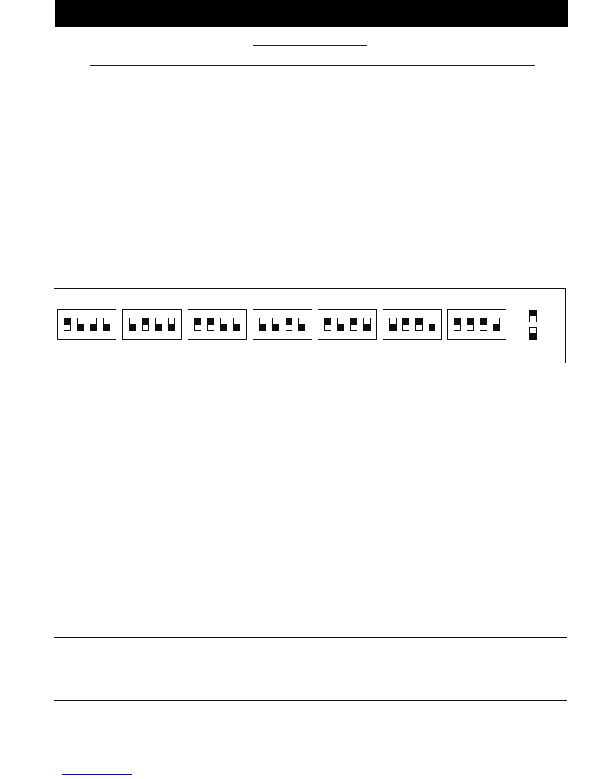
TABLE 1: Data Bus Address Switch Settings
ON
1 2 3 4
ON
1 2 3 4
ON
1 2 3 4
ON
1 2 3 4
Address 1
ON
1 2 3 4
ON
1 2 3 4
ON
1 2 3 4
Address 2
Address 3 Address 4
Address 5 Address 6 Address 7
LEGEND
ON
OFF
Data Bus Terminating Jumper JP1 – This is engages a 120 Ohm resistor for terminating the M1 RS-485 Data Bus. See Data bus wiring instructions before use.
For Data Bus Type 5 Devices (Serial Expanders) the only valid Addresses are 1 thru 7 and therefore the maximum number of Type 5 Devices is 7.
2 - Equipment Setup
Please setup the Lutron equipment and devices and have them all working before proceeding.
2.1 Turn off the power to all equipment before making any wiring connections.
2.2 Wire the M1XSLU to the M1's RS485 data bus. Please follow the recommendations in the M1 Installation book and this manual
for wiring the 4 conductors of the data bus (+12V, A, B, and Neg) to the terminals on the M1XSLU. You should never attach
more than 2 homerun cables directly to the M1 Control! The preferred way to connect multiple bus devices to M1 is to either
daisy chain connect them along each homerun wire, or add a data bus hub device (Elk M1DBH or M1DBHR) in the panel that
will support connection of mulitple homerun cables.
2.3 Wire the IP232 to the M1XSLU using the supplied DB9F to DB9M Serial ribbon cable and DB9M to DB9F Null Modem adapter.
DO NOT use an extension or attempt to make this cord any longer! Be sure to mount the M1XSLU and IP232 in close proximity
to a wired Local Area Network (LAN) connection.
2.4 Wire the IP232 to the LAN using a CAT5 or CAT5 network cable (not supplied). The IP232 converts the serial topology of the
M1XSLU into Ethernet (IP) topology allowing integration over IP to the Lutron Caséta Smartbridge Pro interface.
2.5 Set the data bus address DIP switches on the M1XSLU to a value between 1 and 7 (see Table 1). Be sure the selected address
is not already being used by another Elk serial expander (type 5) device. Each switch has an OFF and On position (binary value
0 or 1). The combination of these switches represents a decimal value between 0 (all Off) and 15 (all On).
2.6 Wire the Smartbridge Pro to the LAN using a CAT5 or CAT6 network cable (not supplied). Power the Lutron device using it's
appropriate lower supply.
2.7 Wire the ELK-IP232 to the customer's LAN using a CAT5 or CAT6 network cable (not supplied). The IP232 will be powered by
the supplied P1216 plug-in AC to DC power supply.
2.8 If all wired connections are complete and secure it is now OK to apply power to the M1 Control which also supplies the power
to the M1XSLU.
2.9 Perform a M1 Bus Module Enrollment to enroll the M1XSLU into the M1 Control. This can be done from a M1 Keypad or the
ElkRP Software. From a Keypad access the Installer level programming and select Menu 01-Bus Module Enrollment. Press
the right arrow key to start the enrollment. When complete press the right arrow (edit) key to view the results. NOTE: The ELK-
M1XSLU shares the same bus type as other serial expanders and will display as a "SerialPExpdr T5" followed by a specic
address (Addr) number. Verify the address displayed matches the address selected in step 2.5 above.
Should it ever be necessary to replace a ELK-M1XSLU; set the replacement unit to the same address as the old unit and perform
the enrollment process. To permanently remove any data bus device perform the enrollment process AFTER disconnecting the
device. This will help avoid a "missing device" trouble condition.
M1XSLC Installation Manual - LUTRON CASÉTA WIRELESS
Page 3
Page 4

LUTRON CASÉTA WIRELESS
3 - Conguring the IP232 IP Interface
Download and install the IP232 Conguration PC software utility from the ELK website (www.elkproducts.com). A copy of the IP232
instructions is packed with the M1XSLC kit with steps for defaulting, resetting, or updating the IP232 rmware if needed.
3.1 Be sure the IP232 is connected to the local area network and is powered by the P1216 plug-in power supply.
3.2 Launch the Conguration Utility and click ‘Search’ to nd the IP232 on the customer's local network. The Device Name (blank),
MAC Address, and IP Address should appear in the display.
192.168.0.251
IMPORTANT: The IP232 Conguration PC Software
must be Ver. 1.2.0 or higher.
The IP232 is factory set for DHCP (dynamic) mode whereby it expects to be assigned a non-permanent IP Address from the
client's router. DHCP makes it easy to add new devices to a network, however that address may change at some future time.
The IP232 can be also assigned to a permanent or STATIC Address. For purposes of interfacing with Lutron the IP232 does not
require a STATIC IP Address since it will always be making outgoing connections to the Lutron Smart Bridge Pro. Caution: If the
IP232 is unable to obtain a DHCP address from the customer's router, it will fall back to a STATIC IP Address of: 192.168.0.251.
This address might not be compatible with the customer's network, making it difcult for the Conguration Utility to discover
it. Should this occur the most likely problems could be: 1) The client's router is not assigning DHCP addresses, 2) The client's
router has reached its limit of available DHCP addresses it can assign, 3) The IP232 may have switched from DHCP mode to
STATIC mode. Consult the IP232 manual for steps on how to force the IP232 from STATIC to DHCP mode and vise versa.
The IP232, Lutron Smart Bridge Pro and the PC running the Conguration Utility must each have their own unique IP Address,
and each address must be compatible with the Network Subnet Mask and Gateway. For solutions on all of this seek additional
help from a knowledgeable network or IT professional.
3.3 Once the IP232 is found and displayed in the window, compare the MAC address against the MAC address printed on the label
attached to the IP232 to make certain it is the correct IP232.
3.4 Click to highlight the found device, then click "Congure" to launch the next screen.
Firmware version must be 1.0.18 or higher. See
IP232 Install manual for steps on updating.
Program the IP232 with a name such as: IP232
for Lutron.
Set the Serial Port settings to: Baud rate 9600,
Handshaking None.
Incoming TCP and Incoming UDP settings are not
important for this application.
Page 4
Leave the IP232 set to DHCP mode since it is
only making an outbound connection to the Lutron
Smart Bridge Pro.
M1XSLC Installation Manual - LUTRON CASÉTA WIRELESS
Page 5

LUTRON CASÉTA WIRELESS
3.5 Verify that the Bootloader version is 1.0.7 or higher and that the Firmware version is 1.0.18 or higher. If either of these are
older versions it will be mandatory to Update these. The Bootloader must be Ver. 1.07 or higher and the Firmware MUST be
Ver.1.0.18 or higher in order for the ELK-IP232 to work with the Lutron Smartbridge Pro.
3.6 Outgoing Connection Rules - The IP232 must be setup to make an outgoing IP connection to the Lutron Smart Bridge Pro
and keep that connection open at all times. If the connection should ever drop the IP232 will automatically reconnect.
TOPOLOGY: ELK-M1 < M1 Databus > ELK-M1XSLU < RS-232 > ELK-IP232 < IP > Lutron Smart Bridge Pro
A. In the Outgoing Connection box click Add New to start the rule wizard.
B. Enter the IP Address of the Lutron Smart Bridge Pro. We highly recommend
this to be a Static Address so that the IP232 can be permanently programmed
with an Address that it can count on to work. Keep in mind that a DHCP
Address may change at some future time. If that should happen then a service
call would be necessary to reprogram the new Address into the IP232!
ELK strongly recommends setting the Lutron Smart Bridge Pro to a STATIC
IP Address.
C. Enter the Port as 23.
D. Set the connection type as TCP then click Next.
E. Q1: When should the unit make this connection?
For instructional purposes ONLY this page
shows an IP Address of 192.168.1.157 for the
Lutron Smart Bridge Pro.
F. Click: "Following power-up or reboot (stays connected indenitely)"
G. Click Next.
H. Q2: Does the remote system require Login (username/password)?
I. Click "YES"
J. Click Next.
K. Take a moment to review the Outgoing Connection Rule and make sure it
looks correct.
L. When everything is vered and correct click Done.
M1XSLC Installation Manual - LUTRON CASÉTA WIRELESS
Page 5
Page 6

LUTRON CASÉTA WIRELESS
3.7 Login Prompt and Reply - The IP232 has the ability to make a telnet connection that is secured with a Username and Password.
This is a requirement for connecting to a Lutron Smart Bridge Pro. The IP232 conguration utility allows full customization of
the prompts and the responses for these security challenges.
IMPORTANT: The precise wording of each challenge and response must be known and entered into the spaces provided.
Listed below are the default prompts and responses that were known to be used by Lutron at the time this manual was printed.
Below are the Login prompts and the
replies shown in BOLD.
For "Prompt for User Name" enter:
login:
For "Prompt for Password" enter:
password:
For "User Name" replay enter:
lutron
For "Password" reply enter:
integration
Note: Password will be hidden unless
the Show box is checked.
All characters are lowercase.
Be sure to include the colon " : " after
the login and password entries.
3.8 The completed conguration should look similar to the above with the exception of the actual IP addresses.
3.9 Click Send Settings (To IP232) to program all of these settings into the ELK-IP232.
3.10 We suggest saving the conguration to hard disk or a thumbdrive for later retrieval. Click Save Settings (To Disk).
3.11 Click Close when done.
Page 6
M1XSLC Installation Manual - LUTRON CASÉTA WIRELESS
Page 7

LUTRON CASÉTA WIRELESS
Lutron
Device ID
1 – Caseta Smartbridge
2
3
4
5
6
7
8
9
10
11
12
13
ELK
Light
Device
1
2
3
4
5
6
7
8
9
10
11
12
13
PLC
(X-10)
Ref.
A01
A02
A03
A04
A05
A06
A07
A08
A09
A10
A11
A12
A13
Lutron
Device ID
14
15
16
17
18
19
20
21
22
23
24
25
26
ELK
Light
Device
14
15
16
17
18
19
20
21
22
23
24
25
26
PLC
(X-10)
Ref.
A14
A15
A16
B01
B02
B03
B04
B05
B06
B07
B08
B09
B10
TABLE 3: M1 Lighting Devices Mapped to Lutron Caseta
ELK
Light
Device
27
28
29
30
31
32
33
34
35
36
37
38
39
PLC
(X-10)
Ref.
B11
B12
B13
B14
B15
B16
C01
C02
C03
C04
C05
C06
C07
Lutron
Device ID
27
28
29
30
31
32
33
34
35
36
37
38
39
ELK
Light
Device
40
41
42
43
44
45
46
47
48
49
50
PLC
(X-10)
Ref.
C08
C09
C10
C11
C12
C13
C14
C15
C16
D01
D02
Lutron
Device ID
40
41
42
43
44
45
46
47
48
49
50
Conguring Lutron Caséta Devices into M1 Lighting
Each Caséta device is assigned a unique Integration Device ID when setup and programmed. Integration to the ELK-M1 involves
mapping these Device IDs to corresponding numbered M1 Light Device locations. See Table 3. M1 Light Device locations that do not
have corresponding Lutron Integration Device IDs should be left blank (unprogrammed). Below are the steps for ElkRP programming
of M1 Lighting. Select ElkRP > Automation > Lighting.
4.1 Download the free Lutron Caséta Wireless App onto your smartphone. This app communicates with the Lutron Smartbridge
Pro over the Internet and becomes the setup and programming tool for the Caséta Wireless devices. After setup this app can
generate and email you an Integration Report displaying the Device IDs, Scenes (buttons), etc. This report is necessary for
setting up the ELK-M1 to communicate to the Smartbridge Pro. NOTE: The Smartbridge Pro will be assigned Device ID #1. All
other devices must be assigned Device IDs #2 through ID #50.
4.2 Launch the Lutron Smartphone App and allow it to connect though the internet to the Lutron Smartbridge Pro.
For assistance in connecting the smartphone app to the Smartbridge Pro follow the Lutron Instructions or contact
Lutron Support. Elk Products cannot assist with this task.
4.3 Proceed here ONLY after the Caséta Wireless Devices and Smartbridge Pro have been setup and programmed.
On the Lutron Caséta smartphone app press the 3 horizontal bars icon in the top left corner (the "hamburger menu").
4.4 Choose the Settings option, then the Advanced option, followed by the Integration option.
4.5 Turn On the Telnet Support by sliding the indicator to the right..
4.6 Choose "Network Settings. The current IP Address and settings of the Smartbridge will display. The address will most likely
be a dynamic (non-permanent) DHCP address. We strongly suggest turning off DHCP and programming a STATIC IP Address
instead. This will allow the IP232 to make an outgoing connection to the Smartbridge that will be permanent.
NOTE: If a STATIC IP Address is not setup and the network DHCP server reassigns a new address to the Smartbridge
Pro, it will be necessary to make a service call to reprogram the new IP Address in the ELK-IP232.
4.7 Choose "Send Integration Report" and enter an Email Address where
you want the integration report to be sent. Hit Send.
4.8 Open your received email and retrieve and/or print the report.
4.9 Launch the ElkRP Software and open or create an account for this job. If this is an existing account le be sure the ElkRP le
M1XSLC Installation Manual - LUTRON CASÉTA WIRELESS
and M1 Panel are synchronized with the same data. If in doubt, connect to M1 and select Receive All or Send All. The intent
is to make sure your database and M1 programming are identical.
Obtaining the Smartbridge
Pro Integration Report
Page 7
Page 8

LUTRON CASÉTA WIRELESS
4.10 Select the Lighting folder from ElkRP > Automation > Lighting to open the Lighting display setup screen.
NOTE: Leave blank any M1
Lighting Device locations
that do not have a Device ID
to be mapped to.
a. Populate the Device 1(A1) row rst. Click on the Name box and enter: Smartbridge Pro.
b. In this same row click in the Format column/box and set it to: Serial Expander.
c. In this same row click in the Type column/box and set it to: Dimmer
d. In this same row leave the Opt column/box and the Show column/box blank (unchecked).
e. In this same row leave the Voice Description column/box blank.
4.11 For each additional Lutron Caséta Wireless device choose and program a name (up to 15 characters) to describe the location
or name of the device. Then ll in the column/boxes according to their matching Device IDs. Note: The Format will always
be Serial Expander. The Type will generally always be Dimmer. The Opt. should always be left Unchecked (Empty). The
Voice Description will generally NOT be used unless the customer intends to use the M1 telephone remote control function
with speech feedback, otherwise leave this blank.
4.12 Click Send to make sure all the above information is stored in the M1 Control. And don't forget to Save the le before exiting.
We also recommend that you periodically perform a database backup of your ElkRP Account for safekeeping.
CAUTION: We do not recommend mixing other lighting technology products (brands) on the same M1 Control.
If it becomes absolutely necessary for you to mix lighting brands then be certain to reserve all lighting
device locations from 1 to 50 for Lutron Caséta Wireless. Mixing of lighting brands requires extreme care
to make certain that no two brands are attempting to utilize the same Lighting Device number locations.
4.13 DISCOVERY MODE: This process is included in the ELK-M1XSLU for support of Lutron RA2. It is not required for Caséta,
but it cannot be skipped or suspended. Upon power up or power cycle of the M1XSLU this process will automatically query
the network for current devices and status. The Discovery process requires approximately ~2 1/4 minutes to complete, during
which the status LED will ash rapidly. Please wait until the M1XSLU Discovery Mode is complete. DO NOT TOUCH OR
DISTURB anything until the rapid ashing changes to a slow 1 sec. ash.
Page 8
M1XSLC Installation Manual - LUTRON CASÉTA WIRELESS
Page 9

LUTRON CASÉTA WIRELESS
5 - Controlling Lutron Caséta Lights or Devices using Rules
5.1 Select ElkRP > Automation > Rules.
5.2 Click New to start a new Rule. Example: Turn ON a Flood Light whenever the System is Armed Away.
5.3 Click WHENEVER > Security/Alarms > Is Armed > Armed Away. Use the drop down arrow to select an area (partition) or
click OK to accept the default "Area 1".
5.4 Click THEN > Control Lighting > Individual. Use the drop down arrow to a light. E.G. Flood Lights [6 (A6)].
5.5 Click Turn On followed by OK. The screen should resemble the following:
WHENEVER Smith Household (Area 8) IS ARMED AWAY
THEN TURN Flood Lights ([6 (A6)] ON FADE RATE=0
5.6 Repeat for any additional lights. Click DONE to complete the Rule.
5.7 Make sure that ElkRP is connected and on-line with the M1 Control, then click Send to Control.
Then Operands are Turn Off, Turn
On, Toggle (ip/op), and Set to Level
(Dim). Note: Dim levels can be used
for virtual button presses on a Pico
Remote or Smartbridge Pro (scenes).
See Table 4.
Fade Rate - A dimmer device can be
set to fade On/Off over time. Settings
are: 0=none, 1=2 Secs, 2=4 Secs,
3=n/a, 4=n/a, 5=32 Secs, 6=46 Secs,
For (Duration) - Allows a duration to
be set for the light, after which it will
revert back to its previous state. Duration can be Days, Hrs, Min, Sec, or a
Custom Setting selection.
This rule turns the Flood Lights ON for
30 seconds. They should turn OFF
automatically 30 secs. after arming
and leaving the building.
Button Presses - M1 has the ability to trigger Lutron virtual buttons (scenes).
To trigger a virtual button (scene), create a M1 rule to send a "Set to Level" command to Device ID #1 (the Lutron Smart Bridge Pro).
Set the % (dim) value to a number from 1 to 50 according to the button (scene) to be triggered. The "Fade Rate" must be set to "0".
Example of a completed rule: THEN SET Smartbridge (A1) to 3% Bright, FADE RATE=0 {This will trigger button 3 (scene 3)
in the Smartbridge Pro and control any associated lights.} To trigger a different button (scene) simply change the % (dim) value.
Note: Percent % (dim) values 2 thru 20 @ Fade Rate=0 are reserved. This means it is not possible to directly control a
Caséta Dimmer to % (dim) values 2 thru 20 UNLESS the Fade Rate is set to a value of 1, 2, 5, 6, or 7. The drawback is
that setting a Caséta Dimmer to dim level 1 thru 20 cannot be immediate. Rather it will be slightly delayed by the value
programmed as the Fade Rate.
Fade Rate Values: 0=immediate, 1=2 seconds, 2=4 seconds, 3=n/a, 4=n/a, 5=~32 seconds, 6=~46 seconds, 7=~60 seconds.
M1XSLC Installation Manual - LUTRON CASÉTA WIRELESS
Page 9
Page 10

LUTRON CASÉTA WIRELESS
TABLE 4: Dim & Fade Rate options for Caseta Dimmers in ElkRP Lighting Rules
Result
Sets Dim level to 1%
Sets Dim level to 2%
Sets Dim level to 3%
Sets Dim level to 4%
Sets Dim level to 5%
Sets Dim level to 6%
Sets Dim level to 7%
Sets Dim level to 8%
Sets Dim level to 9%
Sets Dim level to 10%
Sets Dim level to 11%
Sets Dim level to 12%
Sets Dim level to 13%
Sets Dim level to 14%
Sets Dim level to 15%
Sets Dim level to 16%
Sets Dim level to 17%
Sets Dim level to 18%
Sets Dim level to 19%
Sets Dim level to 20%
Sets Dim level to 21%
Sets Dim level to 22%
Sets Dim level to 23%
Sets Dim level to 24%
Sets Dim level to 25%
Sets Dim level to 26%
Sets Dim level to 27%
Sets Dim level to 28%
Sets Dim level to 29%
Sets Dim level to 30%
Sets Dim level to 31%
Sets Dim level to 32%
Sets Dim level to 33%
Sets Dim level to 34%
Sets Dim level to 35%
Sets Dim level to 36%
Sets Dim level to 37%
Sets Dim level to 38%
Sets Dim level to 39%
Sets Dim level to 40%
Sets Dim level to 41%
Sets Dim level to 42%
Sets Dim level to 43%
Sets Dim level to 44%
Sets Dim level to 45%
Sets Dim level to 46%
Sets Dim level to 47%
Sets Dim level to 48%
Sets Dim level to 49%
Sets Dim level to 50%
Dim
Level
1
2
3
4
5
6
7
8
9
10
11
12
13
14
15
16
17
18
19
20
21
22
23
24
25
26
27
28
29
30
31
32
33
34
35
36
37
38
39
40
41
42
43
44
45
46
47
48
49
50
Fade
Rate
1,2,5,6,7
1,2,5,6,7
1,2,5,6,7
1,2,5,6,7
1,2,5,6,7
1,2,5,6,7
1,2,5,6,7
1,2,5,6,7
1,2,5,6,7
1,2,5,6,7
1,2,5,6,7
1,2,5,6,7
1,2,5,6,7
1,2,5,6,7
1,2,5,6,7
1,2,5,6,7
1,2,5,6,7
1,2,5,6,7
1,2,5,6,7
1,2,5,6,7
1,2,5,6,7
1,2,5,6,7
1,2,5,6,7
1,2,5,6,7
1,2,5,6,7
1,2,5,6,7
1,2,5,6,7
1,2,5,6,7
1,2,5,6,7
1,2,5,6,7
1,2,5,6,7
1,2,5,6,7
1,2,5,6,7
1,2,5,6,7
1,2,5,6,7
1,2,5,6,7
1,2,5,6,7
1,2,5,6,7
1,2,5,6,7
1,2,5,6,7
1,2,5,6,7
1,2,5,6,7
1,2,5,6,7
1,2,5,6,7
1,2,5,6,7
1,2,5,6,7
1,2,5,6,7
1,2,5,6,7
1,2,5,6,7
1,2,5,6,7
Result
Sets Dim level to 51%
Sets Dim level to 52%
Sets Dim level to 53%
Sets Dim level to 54%
Sets Dim level to 55%
Sets Dim level to 56%
Sets Dim level to 57%
Sets Dim level to 58%
Sets Dim level to 59%
Sets Dim level to 60%
Sets Dim level to 61%
Sets Dim level to 62%
Sets Dim level to 63%
Sets Dim level to 64%
Sets Dim level to 65%
Sets Dim level to 66%
Sets Dim level to 67%
Sets Dim level to 68%
Sets Dim level to 69%
Sets Dim level to 70%
Sets Dim level to 71%
Sets Dim level to 72%
Sets Dim level to 73%
Sets Dim level to 74%
Sets Dim level to 75%
Sets Dim level to 76%
Sets Dim level to 77%
Sets Dim level to 78%
Sets Dim level to 79%
Sets Dim level to 80%
Sets Dim level to 81%
Sets Dim level to 82%
Sets Dim level to 83%
Sets Dim level to 84%
Sets Dim level to 85%
Sets Dim level to 86%
Sets Dim level to 87%
Sets Dim level to 88%
Sets Dim level to 89%
Sets Dim level to 90%
Sets Dim level to 91%
Sets Dim level to 92%
Sets Dim level to 93%
Sets Dim level to 94%
Sets Dim level to 95%
Sets Dim level to 96%
Sets Dim level to 97%
Sets Dim level to 98%
Sets Dim level to 99%
Sets Dim level to 100%
Dim
Level
51
52
53
54
55
56
57
58
59
60
61
62
63
64
65
66
67
68
69
70
71
72
73
74
75
76
77
78
79
80
81
82
83
84
85
86
87
88
89
90
91
92
93
94
95
96
97
98
99
100
Fade
Rate
1,2,5,6,7
1,2,5,6,7
1,2,5,6,7
1,2,5,6,7
1,2,5,6,7
1,2,5,6,7
1,2,5,6,7
1,2,5,6,7
1,2,5,6,7
1,2,5,6,7
1,2,5,6,7
1,2,5,6,7
1,2,5,6,7
1,2,5,6,7
1,2,5,6,7
1,2,5,6,7
1,2,5,6,7
1,2,5,6,7
1,2,5,6,7
1,2,5,6,7
1,2,5,6,7
1,2,5,6,7
1,2,5,6,7
1,2,5,6,7
1,2,5,6,7
1,2,5,6,7
1,2,5,6,7
1,2,5,6,7
1,2,5,6,7
1,2,5,6,7
1,2,5,6,7
1,2,5,6,7
1,2,5,6,7
1,2,5,6,7
1,2,5,6,7
1,2,5,6,7
1,2,5,6,7
1,2,5,6,7
1,2,5,6,7
1,2,5,6,7
1,2,5,6,7
1,2,5,6,7
1,2,5,6,7
1,2,5,6,7
1,2,5,6,7
1,2,5,6,7
1,2,5,6,7
1,2,5,6,7
1,2,5,6,7
1,2,5,6,7
For Caseta Dimmers 2 thru 50 the following Dim Levels and Fade Rate options may be programmed
Fade Rate Values: 0=immediate, 1=2 seconds, 2=4 seconds, 3=n/a, 4=n/a, 5=~32 seconds, 6=~46 seconds, 7=~60 seconds.
NOTE: Security Flash & Security Solid - Lutron Caséta does not support Security Flash or Security Solid modes.
Page 10
M1XSLC Installation Manual - LUTRON CASÉTA WIRELESS
Page 11

LUTRON CASÉTA WIRELESS
M1 Lighting Device
#1 (Smartbridge Pro)
Button (Scene) #1
Button (Scene) #2
Button (Scene) #3
Button (Scene) #4
Button (Scene) #5
Button (Scene) #6
Button (Scene) #7
Button (Scene) #8
Button (Scene) #9
Button (Scene) #10
Button (Scene) #11
Button (Scene) #12
Button (Scene) #13
Button (Scene) #14
Button (Scene) #15
Button (Scene) #16
Button (Scene) #17
Button (Scene) #18
Button (Scene) #19
Button (Scene) #20
Button (Scene) #21
Button (Scene) #22
Button (Scene) #23
Button (Scene) #24
Button (Scene) #25
Button (Scene) #26
Button (Scene) #27
Button (Scene) #28
Button (Scene) #29
Button (Scene) #30
Button (Scene) #31
Button (Scene) #32
Button (Scene) #33
Button (Scene) #34
Button (Scene) #35
Button (Scene) #36
Button (Scene) #37
Button (Scene) #38
Button (Scene) #39
Button (Scene) #40
Button (Scene) #41
Button (Scene) #42
Button (Scene) #43
Button (Scene) #44
Button (Scene) #45
Button (Scene) #46
Button (Scene) #47
Button (Scene) #48
Button (Scene) #49
Button (Scene) #50
Set to Level
(Dim Level)
1
2
3
4
5
6
7
8
9
10
11
12
13
14
15
16
17
18
19
20
21
22
23
24
25
26
27
28
29
30
31
32
33
34
35
36
37
38
39
40
41
42
43
44
45
46
47
48
49
50
Fade Rate must
be set to “0”
0
0
0
0
0
0
0
0
0
0
0
0
0
0
0
0
0
0
0
0
0
0
0
0
0
0
0
0
0
0
0
0
0
0
0
0
0
0
0
0
0
0
0
0
0
0
0
0
0
0
TABLE 5: Smartbridge Pro Scene Activations
Name assigned to the Smartbridge Pro Scene
Program M1 Lighting Device #1 to the
following Dim Level and Fade Rate
Example of a rule triggering a programmed Scene that has been stored in
the Smartbridge Pro.
WHENEVER Smith Household (Area 8) IS ARMED AWAY
THEN SET Smartbridge Pro [1(A1)] TO 3% BRIGHT, FADE RATE=0
M1XSLC Installation Manual - LUTRON CASÉTA WIRELESS
Smartbridge Pro
Page 11
Page 12

Page 12
M1XSLC Installation Manual - LUTRON CASÉTA WIRELESS
 Loading...