

Page 1
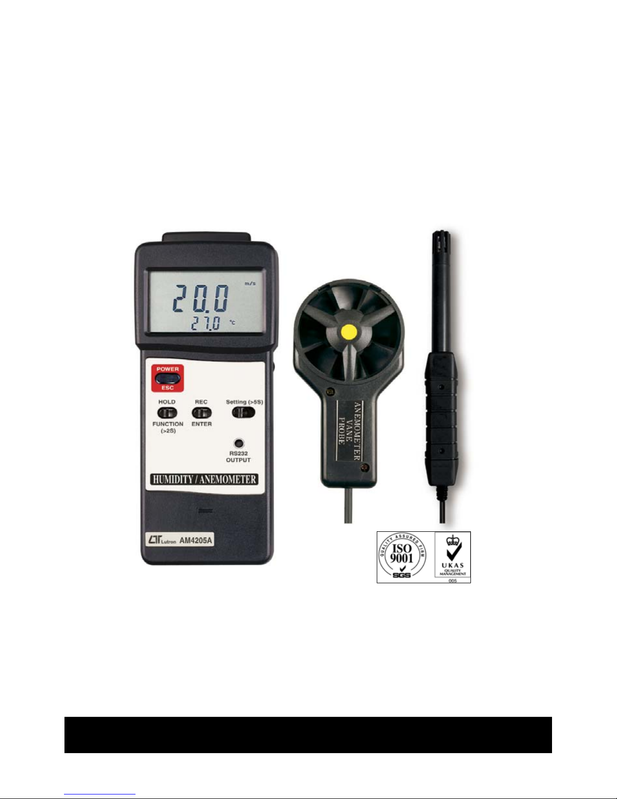
+ Type K/J TEMP.
HUMIDITY /
A
NEMOMETER
Model : AM-4205A
Your purchase of this HUMIDITY/ANEMOMETER marks a step
forward for you into the field of precision measurement.
Although this METER is a complex and delicate instrument, its
durable structure developed. Please read the following
instructions carefully and always keep this manual within easy
reach.
OPERATION MANUAL
Page 2

TABLE OF CONTENTS
1. FEATURES..................................................................... 1
2. SPECIFICATIONS........................................................... 2
2-1 General Specifications............................................... 2
2-2 Electrical Specifications ............................................ 5
3. FRONT PANEL DESCRIPTION.......................................... 7
3-1 Display.................................................................... 7
3-2 Power Button ( ESC Button )..................................... 7
3-3 Hold Button ( Function Button )................................. 7
3-4 REC Button ( Enter Button )...................................... 7
3-5 Settin
g
Button .........................................................7
3-6 RS-232 Output Terminal...........................................
.
7
3-7 Vane Probe Head.....................................................
.
7
3-8 Vane Probe Handle................................................... 7
3-9 Vane Probe Plu
g
.......................................................7
3-10 Humidity Probe Head ............................................. 7
3-11 Humidity Probe Handle...........................................
.
7
3-12 Humidity Probe Plu
g
............................................... 7
3-13 Humidity/Anemometer Socket.................................
.
7
3-14 Thermometer Socket..............................................
.
7
3-15 Battery Compartment/Cover.................................... 7
4. MEASURING PROCEDURE............................................... 9
4-1 Anemometer............................................................ 9
4-2 Humidity meter........................................................10
4-3 Thermometer...........................................................10
4-4 Both Anemometer/Thermometer...............................11
4-5 Both Humidity meter/Thermometer...........................
.
11
4-6 Data Hold................................................................12
4-7 Data Record (Max, Min readin
g
)................................ 12
5. ADVANCED MEASURING PROCEDURE..............................13
5-1 Chan
g
e the measuring unit.......................................14
5-2 Chan
g
e the thermocouple to type K or type J.............14
5-3 Chan
g
e the Temp , unit....................................
.
℃℉ 14
5-4 Auto power On/Off...................................................15
5-5 Code enterin
g
for the further calibration usage...........15
6. RS232 PC SERIAL INTERFACE.........................................16
7. BATTERY REPLACEMENT................................................18
8. OPTIONAL ACCESSORIES...............................................
.
18
Page 3

1. FEATURES
* Anemometer, Humidity meter and type K/J Thermometer
are combined into one meter, intelligent design.
* Microprocessor circuit assures maximum possible accuracy,
provides special functions and features.
* Large LCD with two display, easy readout.
* Low-friction ball vane wheels is accurate in both high &
low velocities for anemometer.
* Thin-film capacitance sensor for humidity measurement,
high precision.
* Records Maximum & Minimum readings with recall.
* Data hold.
* Auto shut off saves battery life.
* RS 232 PC serial interface.
* The portable anemometer provides fast, accurate readings
and the convenience of a remote sensor separately.
* Humidity meter with the separate probe.
* Multi-functions for air flow measurement: m/s, km/h,
ft/min, knots. mile/h.
* Build in temperature , measurement.℃℉
* Used the durable, long-lasting components.
* Heavy duty and deluxe hard carrying case, easy
carryout & storage.
* Wide applications : To check air conditioning & heating
systems, measure air velocities, wind speeds, humidity
temperature...etc.
* Available for the HVAC applications.
1
Page 4

2. SPECIFICATIONS
2-1 General Specifications
Circuit Custom one-chip of microprocessor
LSI circuit.
Display * LCD size : 60 mm x 33 mm
* Dual function meter's display.
Measurement
Anemometer :
m/s ( meters per second )
km/h ( kilometers per hour )
ft/min ( feet/per minute )
knots ( nautical miles per hour )
mile/h ( miles per hour )
Temperature - , .℃℉
Humidity meter :
%RH ( Relative Humidity ).
Temperature - , .℃℉
Type K/J thermometer
Sensor
Anemometer :
Structure Air velocity :
Conventional twisted van arm and
low friction ball bearing design.
Temperature : Precision thermistor.
Humidity meter :
Humidity :
High precision thin-film
capacitance sensor.
Temperature : Precision Temp. sensor.
Thermometer :
Type K/J thermocouple probe.
2
Page 5

Type K/J
Input Socket :
Thermometer Standard 2 pin thermocouple socket.
structure
Linear Compensation :
Linear Compensation for the full range.
Temperature Compensation :
Automatic cold junction compensation
both type K/J thermometer
Data hold To freeze the display reading on the
LCD display.
Memory Records Maximum & Minimum readings
Recall with recall.
Sampling Approx. 1 sec.
Time
Power Auto shut off to save battery life or
Management manual off by push button.
Over
Show " ".
Indication
Data Output RS 232 PC serial interface.
Operating 0 to 50 ( 32 to 122 ).℃℉
Temperature
Operating Less than 80% RH.
Humidity
Power Supply DC 9V battery ( heavy duty ), 006P,
MN1604 ( PP3 ) or equivalent.
Power
Type K/J thermometer :
Consumption Approx. DC 6 mA
Anemometer :
Approx. DC 11 mA
Humidity :
Approx. DC 7 mA
Weight 256 g/0.56 LB, main instrument.
3
Page 6

Dimension
Main instrument:
180x72x32 mm (7.1x2.8x1.3 inch).
Anemometer probe :
Round, 72 mm Dia.
Humidity Probe:
197 mm ( 7.8 inch ) in length.
Accessories Instruction manual..................1 PC.
Included Anemometer probe.................
.
1 PC.
Humidity Probe.......................
.
1 PC.
Carryin
g
case..........................1 PC.
Optional * Type K thermocouple probe,
Accessories TP-01, TP-02A. TP-03, TP-04.
* RS232 cable, UPCB-02.
* USB cable, USB-01.
* Data Acquisition software,
SW-U801-WIN.
* AC to DC 9V adapter, AP-9VB.
4
Page 7
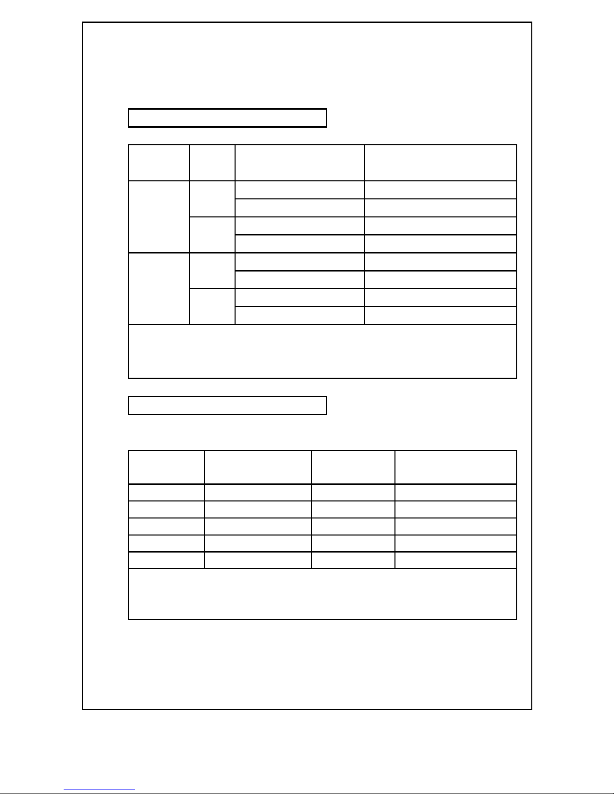
2-2 Electrical Specifications (23±5 )℃
Type K/J Thermometer
Sensor Reso- Range Accuracy
Type lution
Type K 0.1 ℃ -50.0 to 1300.0 ℃ ± ( 0.4 % + 0.8 )℃
-50.1 to -199.9 ℃ ± ( 0.4 % + 1 )℃
0.1 ℉ -58.0 to 2372.0 ℉ ± ( 0.4 % + 1.5 )℉
-58.1 to -327.8 ℉ ± ( 0.4 % + 1.8 )℉
Type J 0.1 ℃ -50.0 to 1100.0 ℃ ± ( 0.4 % + 0.8 )℃
-50.1 to -199.9 ℃ ± ( 0.4 % + 1 )℃
0.1 ℉ -58.0 to 2012.0 ℉ ± ( 0.4 % + 1.5 )℉
-58.1 to -327.8 ℉ ± ( 0.4 % + 1.8 )℉
*
Accuracy value is specified for the meter only.
*
Temp. probe ( Type K, TP-01 TP-02A, TP-03. TP-04 ) is the
optional accessories, refer page 22.
Anemometer
A. Air velocity
Measure- Range Resolution Accuracy
ment tion
m/S 0.4 - 25.0 m/s 0.1 m/s ± (2% + 0.2 m/s)
km/h 1.4 - 90.0 km/h 0.1 km/h ± (2% + 0.8 km/h)
mph 0.9 - 55.9 mile/h 0.1 mile/h ± (2% + 0.4 mile/h)
knot 0.8 - 48.6 knots 0.1 knots ± (2% + 0.4 knots)
FPM 80 - 4930 ft/min 1 ft/min ± (2%+40 ft/min.)
Note:
m/S - meters per second km/h - kilometers per hour
FPM - feet/per minute knot - nautical miles per hour
mph - miles per hour (international knot)
5
Page 8

B. Temperature
Measuring Range 0 to 50 /32 to 122 ℃℃℉ ℉
Resolution 0.1 /0.1 ℃℉
Accuracy ± 0.8 /1.5 ℃℉
Humidity/Temp. meter
A. Humidity
Measuring Range 10 % to 95 % R.H.
Resolution 0.1 % R.H.
Accuracy 70% RH ≧ ± (3% reading + 1% RH).
< 70% RH ± 3% RH.
B. Temperature
Measuring Range 0 to 50 /32 to 122 ℃℃℉ ℉
Resolution 0.1 /0.1 ℃℉
Accuracy ± 0.8 /1.5 ℃℉
*
Above specification tests under the environment RF Field
Strength less than 3 V/M & frequency less than 30 MHz only.
6
Page 9

3. FRONT PANEL DESCRIPTION
Fig. 1
7
Page 10

Fig. 2
3-1 Display
3-2 Power Button ( ESC Button )
3-3 Hold Button ( Function Button )
3-4 REC Button ( Enter Button )
3-5 Setting Button
3-6 RS-232 Output Terminal
3-7 Vane Probe Head
3-8 Vane Probe Handle
3-9 Vane Probe Plug
3-10 Humidity Probe Head
3-11 Humidity Probe Handle
3-12 Humidity Probe Plug
3-13 Humidity/Anemometer Socket
3-14 Thermometer Socket
3-15 Battery Compartment/Cover
8
Page 11

4. MEASURING PROCEDURE
4-1 ANEMOMETER
1)Install the " Vane Probe Plug " ( 3-9, Fig. 1 ) into the
" Anemometer Socket " ( 3-13, Fig. 2 ).
2)Power on the meter by pressing the " Power Button "
( 3-2 , Fig. 1 ) once.
3)Hold the " Vane Probe Handle " ( 3-9, fig. 1 ) by
hand and let the " Vane Probe Head " ( 3-8, Fig. 1 )
face against the measuring air flow source, then the
" Display " ( 3-1, Fig. 1 ) will show air velocity and
the air temperature value together.
Measuring Consideration :
The yellow dot mark on the " Sensor
head " indicates the direction that need to
face against the air flow.
The anemometer air velocity unit is default to " m/s ".
If intend change to the other air velocity unit such as
km/h, mph, FPM or knot with default, the detail
procedures please refer
5-1 Change the measuring unit, page 14.
The anemometer air temperature unit is default to " ".℃
If intend change temperature unit to " ", the detail ℉
procedures please refer
5-3 Change the Temp , unit, page 14.℃℉
9
Page 12

4-2 HUMIDITY METER
1)Install the " Humidity Probe Plug " ( 3-12, Fig. 1 ) into the
" Humidity Socket " ( 3-13, Fig. 2 ).
2)Power on the meter by pressing the " Power Button "
( 3-2 , Fig. 1 ) once.
3)The display will show the humidity ( %RH ) and
temperature value that sening from " Humidity Probe Head "
( 3-10, Fig. 1) directly.
When the humidity values of tested environment be
changed, it need to take a few minutes to get the stable
" %RH " reading.
The humidity temperature unit is default to " ".℃
If intend change temperature unit to " ", the detail℉
procedures please refer
5-3 Change the Temp , unit, page 14.℃℉
4-3 Thermometer
1)Connect the plug of the Temp. probe ( optional, such as
type K probe, TP-01, TP-02A, TP-03, TP-04 ) into the "
Thermometer socket " ( 3-14, Fig. 2 ).
2)Power on the meter by pressing the " Power Button "
( 3-2 , Fig. 1 ) once.
3
)
The display will show the Temp. value that measuring
from the Temp. probe's head.
The thermometer mode is default to " type K ".
If intend change the Temp. mode to " type J " with
default, the detail procedures please refer
5-2 Change thermocouple type to K or J , page 14.
The temperature unit is default to " ", if intend change℃
temperature unit to " ". ℉
The detail procedures please refer
5-3 Change the Temp , unit, page 14.℃℉
10
Page 13

4-4 Both Anemometer/Thermometer
1)Install the " Vane Probe Plug " ( 3-9, Fig. 1 ) into the
" Anemometer Socket " ( 3-13, Fig. 2 ).
Connect the plug of the Temp. probe ( optional, such as
type K probe, TP-01, TP-02A, TP-03, TP-04 ) into the "
Thermometer socket " ( 3-14, Fig. 2 ).
2)Power on the meter by pressing the " Power Button "
( 3-2 , Fig. 1 ) once.
3)The main measuring procedures are same as above
chapter and chapter 4-3.
4)Press the " Function Button " ( 3-3, Fig. 1 ) continuously
at least 2 seconds, the function will change from " Air
velocity " to " Thermometer " in cycling.
4-5 Both Humidity meter/Thermometer
1)Install the " Humidity Probe Plug " ( 3-12, Fig. 1 ) into the
" Humidity Socket " ( 3-13, Fig. 2 ).
Connect the plug of the Temp. probe ( optional, such as
type K probe, TP-01, TP-02A, TP-03, TP-04 ) into the "
Thermometer socket " ( 3-14, Fig. 2 ).
2)Power on the meter by pressing the " Power Button "
( 3-2 , Fig. 1 ) once.
3)The main measuring procedures are same as above
chapter 4-2 and chapter 4-3.
4)Press the " Function Button " ( 3-3, Fig. 1 ) continuously
at least 2 seconds, the function will change from "
Humidity " to " Thermometer " in cycling.
11
Page 14

4-6 Data Hold
During the measurement, pushing the " Data Hold
Button " ( 3-3, Fig. 1 ) will hold the measured value &
the LCD will indicate " HOLD " symbol.
* Push the "Data Hold Button" again to release the
data hold function.
4-7. Data Record ( Max., Min.
)
*
The data record function records the maximum and
minimum readings. Press the " REC. Button " ( 3-4, Fig. 1
) once to start the Data Record function and there
will be a " REC " symbol on the display.
*
With the " REC " symbol on the display :
a)Press the " REC. Button " ( 3-4, Fig. 1 ) once, the
" REC MAX " symbol along with the maximum value
will appear on the display.
Press the " REC button " ( 3-4, Fig. 1 ) again, the
" REC MIN " symbol along with the minimum value
will appear on the display.
If intend to delete the maximum ( minimum )
value, press the " Hold button " ( 3-3, Fig. 1 )
once, the display will show the " REC " symbol
only and execute the memory function
continuously.
b)To exit the memory record function, just press the
" REC " button for 2 seconds at least. The display will
revert to the current reading.
12
Page 15

5. ADVANCED SETTING PROCEDURES
Before executing Advanced Setting Procedures,
exit the " Hold function " and the Record "
function first.
* Press " Setting Button " continuously at
least 5 seconds to enter the setting function.
* After already set the desiring value ( function ),
press the " Enter button " to save with default.
* Press the " Esc button " to escape the setting
procedures.
a. Hold the " Setting Button " ( 3-5, Fig. 1 ) at least five
seconds will enter the Advanced Setting Procedures.
b. One by one to press the " Setting Button " ( 3-5, Fig. 1 )
once a while to select the main setting function in sequence
and show the text the lower display as :
Unit...... Change the measurement unit
K...........
.
Change thermocouple type to type K or type J
..........
.
℃ Change the Temp , unit℃℉
OFF....... Auto power ON/OFF management
Code......Code entering for the further calibration usage
13
Page 16

5-1 Change the measuring unit
Change the measurement unit are available for
Anemometer
a. Use " Function button " ( 3-3, Fig. 1 ) to select the desiring
measuring unit.
Anemometer
m/S, km/h, mph, knot, FPM
b. After select the desiring unit, press the " Enter
button " ( 3-4, Fig. 1 ) to save the data with default.
5-2 Change thermocouple type to K or J
Change " thermocouple type to K or J " only available
for
Type K/J Thermometer
a. Use " Function button " ( 3-3, Fig. 1 ) to select " K " or " J ".
b. After select the desiring value ( K or J ), press the
" Enter button " ( 3-4, Fig. 1 ) to save the data with
default.
5-3 Change the Temp , unit℃℉
Change the " Temp , unit " only available for the℃℉
Anemometer meter
Humidity meter
Type K/J Thermometer
a. Use " Function button " ( 3-3, Fig. 1 ) to select " " ℃
or " ".℉
b. After select the desiring value ( or ), press the ℃℉
" Enter button " ( 3-4, Fig. 1 ) to save the data with
default.
14
Page 17

5-4 Auto power On/Off
( Lower display show " OFF " )
a. Use " Function button " ( 3-3, Fig. 1 ) to select " YES "
or " no ".
* YES : Auto power off.
* no : Auto power disable.
b. After select the desiring function ( YES or no ), press the
" Enter button " ( 3-4, Fig. 1 ) to save the function with
default.
5-5 Code entering for the further calibration
usage
( Lower display show " CodE" )
The upper display will show 100.
The code setting is used for the further calibration usage.
It do not enter any new code, just press the " Enter button
" ( 3-4, Fig. 1 ) will finish the Advanced Setting Procedure.
15
Page 18

6. RS232 PC SERIAL INTERFACE
The instrument has RS232 PC serial interface via a 3.5
mm terminal ( 3-6, Fig. 1 ).
The data output is a 16 digit stream which can be
utilized for user's specific application.
A RS232 lead with the following connection will be
required to link the instrument with the PC serial port.
Meter PC
(3.5 mm jack plug) (9W 'D" Connector)
Center Pin...................................Pin 4
Ground/shield............................Pin 2
Pin 5
The 16 digits data stream will be displayed in the
following format :
D15 D14 D13 D12 D11 D10 D9 D8 D7 D6 D5 D4 D3 D2 D1 D0
16
Page 19

Each digit indicates the following status :
D15 Start Word
D14 4
D13 When send the upper display data = 1
When send the lower display data = 2
D12 & D11 Annunciator for Display
= 01 ℃ = 02℉ m/S = 08
km/h = 10 mph = 12 knot = 09
FPM = 11 %RH = 04
D10 Polarity
0 = Positive 1 = Negative
D9 Decimal Point(DP), position from right to the
left
0 = No DP, 1= 1 DP, 2 = 2 DP, 3 = 3 DP
D8 to D1 Display reading, D8 = MSD, D1 = LSD.
For example :
If the display reading is 1234, then D8 to
D1 is : 00001234
D0 End Word
RS232 setting
Baud rate 9600
Parity No parity
Data bit no. 8 Data bits
Stop bit 1 Stop bit
17
Page 20

7. BATTERY REPLACEMENT
1)
When the left corner of LCD display show " ", it
is necessary to replace the battery. However, in-spec.
measurement may still be made for several hours after
low battery indicator appears before the instrument
become inaccurate.
2)Open the " Battery Cover " ( 3-15, Fig. 2 ) away from
the instrument and remove the battery.
3)Replace with 9V battery ( Alkaline or Heavy duty type )
and reinstate the cover.
4)Make sure the battery cover is secured after changing
the battery.
8. OPTIONAL ACCESSORIES
RS232 cable Interface cable ( isolated cable )
UPCB-02 that used to connect the meter to
the computer ( COM port ).
USB cable Interface cable that used to
USB-01 connect the meter to the computer
( USB port ).
Data Acquisition * The SW-U801-WIN is a multi
software displays ( 1/2/4/6/8 displays )
SW-U801-WIN powerful application software,
provides the functions of data
logging system, text display,
angular display, chart display,
data recorder high/low limit, data
query, text report, chart report..
.xxx.mdb data file can be
retrieved for EXCEL, ACESS..,
wide intelligent applications.
18
Page 21

(Type K) TP-01 * Max. short-tern operating
Temperature: 300 (572 ).℃℉
* It is an ultra fast response
naked-bead thermocouple
suitable for many general purpose
application.
Thermocouple * Measure Range :
Probe -50 to 900 , -50 to 1650 .℃℉
(Type K), TP-02A * Dimension:10cm tube,3.2mm Dia.
Thermocouple * Measure Range :
Probe -50 to 1200 , -50 to 2200 .℃℉
(Type K), TP-03 * Dimension: 10cm tube, 8mm Dia.
Surface Probe * Measure Range :
(Type K), TP-04 -50 to 400 , -50 to 752 .℃℉
* Size :
Temp. sensing head - 15 mm Dia.
Probe length - 120 mm.
ACV to DC 9V ACV to DC 9V adapter.
adapter, AP-9VB Output plug is used the DC 9V
battery snap.
19
0610-AM4205A
 Loading...