

Page 1
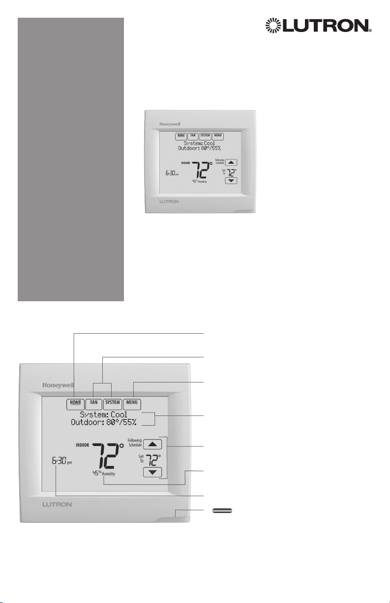
Reference to key features
* Password is the date code.
Wireless Thermostat
Installation Guide
Current display. Underlined label
signifies the current display.
Mode control buttons. Use to change
settings for Fan or System Heat/Cool.
Menu. Select options to: set schedules,
view equipment status, change IAQ
settings, access installer options*, etc.
Current status. Shows system mode
(heat/cool), outdoor temperature and
humidity.
Current schedule. Shows desired
temperature and schedule status.
Indoor conditions. Shows indoor
temperature and humidity.
Current Time.
Alert Light. On when alert
message is active or system is set to
Em Heat.
Page 2
1-855-733-5465
yourhome.honeywell.com
Honeywell
Golden
M35343A
NO MERCURY
ATTENTION: MERCURY RECYCLING NOTICE
This product does not contain mercury. However, this
product may replace a product that contains mercury.
Hg
Mercury and products containing mercury should not be
discarded in household trash.
For more information on how and where to properly recycle
a thermostat containing mercury in the United States,
please refer to the Thermostat Recycling Corporation at
www.thermostat-recycle.org.
For mercury thermostat recycling in Canada, please refer
to Switch the Stat at
www.switchthestat.ca
Getting started
Follow these basic steps to install this thermostat,
set installer options, and connect to the Wi-Fi
network.
NOTE: For the product specifications, please go
to www.lutron.com
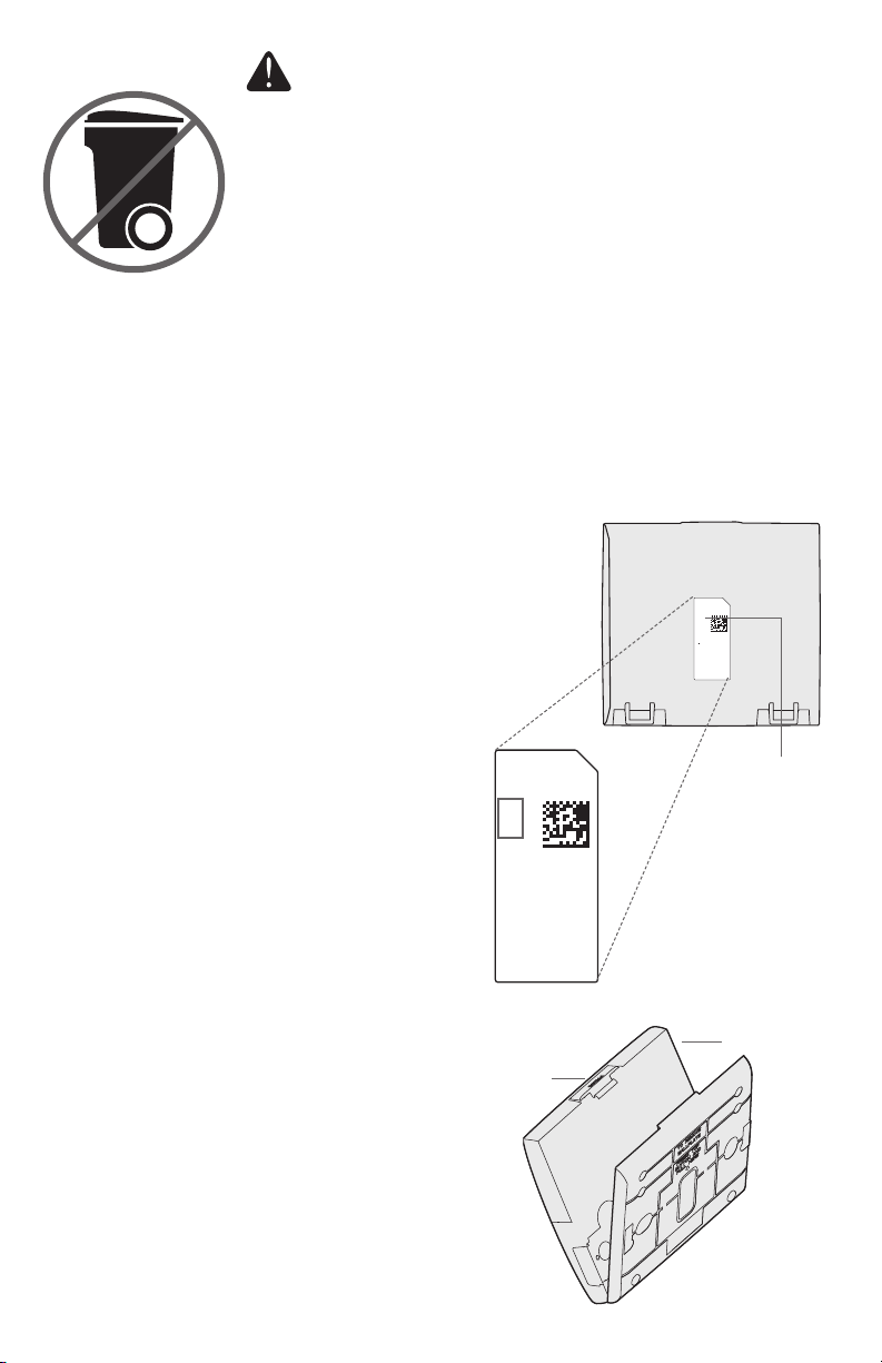
Installing the thermostat
1 Separate wallplate from thermostat.
Press button on top and pull to remove
the wallplate.
RoHs Compliant
Conformité RoHs
Assembled in Mexico
Assemblé au Mexique
1524
Button
Thermostat (back view)
RoHs Compliant
Conformité RoHs
Assembled in Mexico
Assemblé au Mexique
1524
1
TH8321WF1001
Residential/Résidentiel
1-800-468-1502
http://yourhome.honeywell.com
Commercial/Commerciale
1-888-245-1051
http://customer.honeywell.com
Honeywell, Golden Valley, MN 55422
Password
(Date Code)
Valley, MN 55422
Thermostat
2
Wallplate
(back view)
Page 3

CONVENTIONAL
CONVENTIONAL
2 Mount wallplate as shown.
Mount new wallplate using screws
and anchors included with the
thermostat.
Drill 3/16-in holes for drywall.
Drill 7/32-in holes for plaster.
3 Connect power.
24VAC power is required. Connect
common side of transformer to C
terminal.
Wallplate
S1
C
K
R
R
U1
U1
U2
U2
C
K
RC
R
U1
U1
U2
U2
HEAT PUMP
S1
S1
S1
C
W
O/B
Y
Y
G
G
AUX
W2
-E
Y2
Y2
L/A
A
S1
S1
S1
S1
O/B
W
Y
Y
G
G
AUX
W2
-E
Y2
Y2
A
L/A
4 Wire the thermostat.
Refer to the table and wiring
diagrams on the next page.
a Turn on 24VAC NOW.
24VAC (C wire) is required.
5 Mount thermostat on wallplate.
Align thermostat at bottom and
snap into place as shown.
3
C
K
RC
R
U1
U1
U2
U2
Thermostat
HEAT PUMP
S1
S1
S1
S1
O/B
W
Y
Y
G
G
AUX
W2
-E
Y2
Y2
A
L/A
Wallplate
Page 4
Terminal Designations
SYSTEM
1
1
SYSTEM
TRANSFORMER
Conventional System Heat Pump
Terminal Description Terminal Description
Common wire from secondary side of
C
cooling transformer (if 2 transformers).
Rc* Cooling power. Rc Cooling power.
R* Heating power. R Heating power.
W Heat Stage 1 O/B Changeover valve for heat pumps.
W2 Heat Stage 2 AUX-E Backup Heat/Emergency Heat
Y Compressor Stage 1 Y Compressor Stage 1
Y2 Compressor Stage 2 Y2 Compressor Stage 2
G Fan Relay G Fan Relay
Connect to Economizer Module or
A
Lighting Panel (TOD).
U1 / U1
S1 / S1
Universal relay for humidification,
dehumidification, ventilation, or a stage of
heating/cooling.
Universal input for a wired indoor, outdoor
or discharge sensor.
U1 / U1
S1 / S1
K** Connect to K on Wire Saver module. K** Connect to K on Wire Saver module.
Common wire from secondary side of
C
cooling transformer.
Connect to Compressor Monitor, Zone
L/A
Panel, Economizer Module or Lighting
Panel (TOD).
Universal relay for humidification,
dehumidification, ventilation, or a stage of
heating/cooling.
Universal input for a wired indoor, outdoor
or discharge sensor.
* Remove factory installed jumper for two transformer systems.
** The THP9045A1023 Wire Saver module is used on heat/cool systems when you only have four wires at the thermostat and you
need a fifth wire for a common wire. Use the K terminal in place of the Y and G terminals on conventional or heat pump systems to
provide control of the fan and the compressor through a single wire—the unused wire then becomes your common wire. See THP9045
instructions for more information.
TRANSFORMER
C
THERMOSTAT
C
K
R
C
R
U1
U1
OR
POWERED
HUMIDIFIER,
DEHUMIDIFIER
OR VENTILATOR
THERMOSTAT
C
K
C
R
R
1
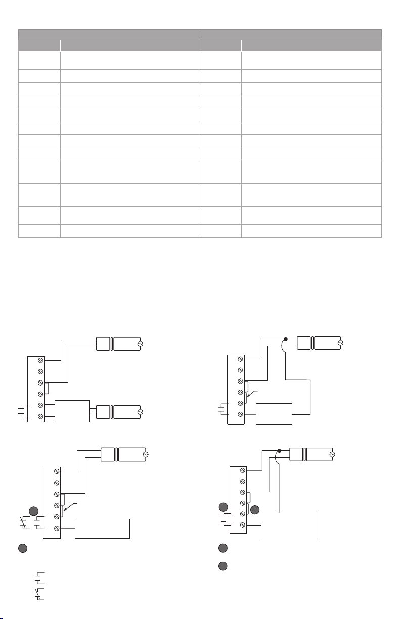
U1
U1
Wire the thermostat universal relay to the low speed fan
for dehumidication control at the equipment. The
thermostat relay can be set to normally open or
normally closed in the thermostat installer setup.
R
FIELD INSTALL JUMPER
BETWEEN R AND U1
DEHUMIDIFICATION
WITH LOW SPEED FAN
24
VAC
HUM, DEHUM OR
VENT TRANSFORM-
ER
24
VAC
C
24
VAC
R
120
VAC
120
VAC
120
VAC
Normally open, dry contacts
Normally closed, dry contacts
NON-POWERED HUMIDIFIER, DEHUMIDIFIER OR VENTILATORPOWERED HUMIDIFIER, DEHUMIDIFIER OR VENTILATOR
THERMOSTAT
C
K
R
C
FIELD INSTALL JUMPER
R
BETWEEN R AND U1
U1
NON-POWERED
U1
CONNECTING A HEAT OR COOL STAGE TO U1DEHUMIDIFICATION WITH LOW SPEED FAN
THERMOSTAT
1
2
HUMIDIFIER,
DEHUMIDIFIER
OR VENTILATOR
C
K
R
C
R
2
U1
U1
U1 terminals are normally open dry contacts when set
up for a stage of heating or cooling.
You must install a eld jumper if the stage of heating
or cooling is powered by system transformer. Do NOT
install a eld jumper if the stage of heating has its own
transformer.
HEAT STAGE 3, COOL
STAGE 3, BACKUP HEAT
STAGE 2 FOR HEAT
PUMPS, OR GEOTHERMAL
RADIANT HEAT
C
R
TRANSFORMER
C
24
VAC
R
SYSTEM
TRANSFORMER
24
VAC
120
VAC
VAC
120
4
Page 5
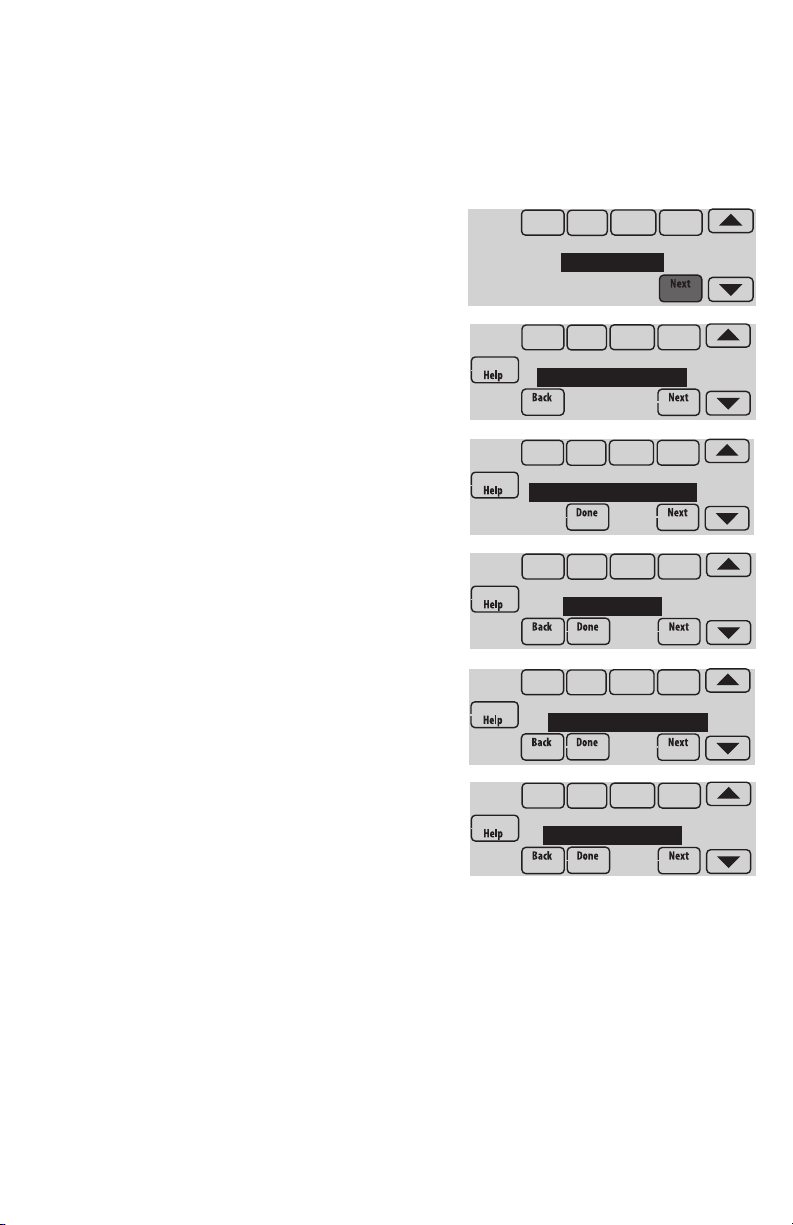
Performing installer setup
Setup options define the type of system you are installing and preferences for the
display.
1 Follow prompts on the screen to select the appropriate options. Among the
screens you might see will be options for:
1.1 Application, either Residential or
Commercial.
1.2 Thermostat Name, which will enable
you to identify it if you’re installing
more than one thermostat (for a zoned
HVAC application, for instance).
1.3 Thermostat Type, either programmable
or not, depending on preference.
1.4 Temperature scale, either Fahrenheit
or Celsius.
1.5 Use outdoor temp.
NOTE: Choose WIRED/INTERNET if your
application will require a wired sensor, or
will use the Internet for weather data.
1.6 The type of heating system.
1.7 For all installer options, press the s or
t buttons to change the option.
1.8 Press Next to move to the next setting,
and Done when setup is complete.
APPLICATION
residential
THERMOSTAT NAME
THERMOSTAT
THERMOSTAT TYPE
programmable
TEMPERATURE SCALE
fahrenheit
USE OUTDOOR TEMP
wired / internet
HEATING SYSTEM
conv. forced air
5
Page 6
Wiring
1H/1C System (1 transformer)
Rc Power [1]
R [R+Rc joined by jumper]
W Heat relay
Y Compressor contactor
G Fan relay
C 24VAC common
S1 Optional outdoor/remote sensor
Heat Only System
Rc Power [1]
R [R+Rc joined by jumper]
W Heat relay
C 24VAC common
S1 Optional outdoor/remote sensor
Heat Only System (Series 20)
Rc [R+Rc joined by jumper]
R Series 20 valve terminal “R” [1]
W Series 20 valve terminal “B”
Y Series 20 valve terminal “W”
C 24VAC common
S1 Optional outdoor/remote sensor
2H/2C System (1 transformer)
Y2 Cool relay 2
W2 Heat relay 2
Rc Power [1]
R [R+Rc joined by jumper]
W Heat relay 1
Y Cool relay 1
G Fan relay
C 24VAC common
S1 Optional outdoor/remote sensor
1H/1C System (2 transformers)
Rc Power (cooling transformer) [1, 2]
R Power (heating transformer) [1, 2]
W Heat relay
Y Compressor contactor
G Fan relay
C 24VAC common [3]
S1 Optional outdoor/remote sensor
Heat Only System With Fan
Rc Power [1]
R [R+Rc joined by jumper]
W Heat relay
G Fan relay
C 24VAC common
S1 Optional outdoor/remote sensor
Cool Only System
Rc Power [1]
R [R+Rc joined by jumper]
Y Compressor contactor
G Fan relay
C 24VAC common
S1 Optional outdoor/remote sensor
2H/2C System (2 transformers)
Y2 Cool relay 2
W2 Heat relay 2
Rc Power (cooling transformer) [1, 2]
R Power (heating transformer) [1, 2]
W Heat relay 1
Y Cool relay 1
G Fan relay
C 24VAC common [3]
S1 Optional outdoor/remote sensor
See [notes] below
[1] Power supply. Provide disconnect means and overload protection as required.
[2] Remove jumper for 2-transformer systems.
[3] Common connection must come from cooling transformer if a 2 transformer installation.
6
Page 7
Wiring
1H/1C Heat Pump (no auxiliary heat)
Rc Power [1]
R [R+Rc joined by jumper]
O/B Changeover valve [4]
Y Compressor relay
G Fan relay
C 24VAC common
S1 Optional outdoor/remote sensor
2H/1C Heat Pump (with auxiliary heat)
L Equipment monitor [5]
Aux/E Auxiliary/Emergency heat relay (Heat 2)
Rc Power [1]
R [R+Rc joined by jumper]
O/B Changeover valve [4]
Y Compressor relay
G Fan relay
C 24VAC common
S1 Optional outdoor/remote sensor
2H/2C Heat Pump (no auxiliary heat)
Y2 Compressor 2 relay
Rc Power [1]
R [R+Rc joined by jumper]
O/B Changeover valve [4]
Y Compressor 1 relay
G Fan relay
C 24VAC common
S1 Optional outdoor/remote sensor
3H/2C Heat Pump (with auxiliary heat)
Y2 Compressor 2 relay
L Equipment monitor [5]
Aux/E Auxiliary/Emergency heat relay (Heat 2)
Rc Power [1]
R [R+Rc joined by jumper]
O/B Changeover valve [4]
Y Compressor 1 relay
G Fan relay
C 24VAC common
S1 Optional outdoor/remote sensor
See [notes] below
[1] Power supply. Provide disconnect means and overload protection as required.
[4] O/B set to control as either O or B in installer setup.
[5] Heat pump reset (powered continuously when thermostat is set to Em. Heat; system monitor when
set to Heat, Cool, or Off).
7
Page 8

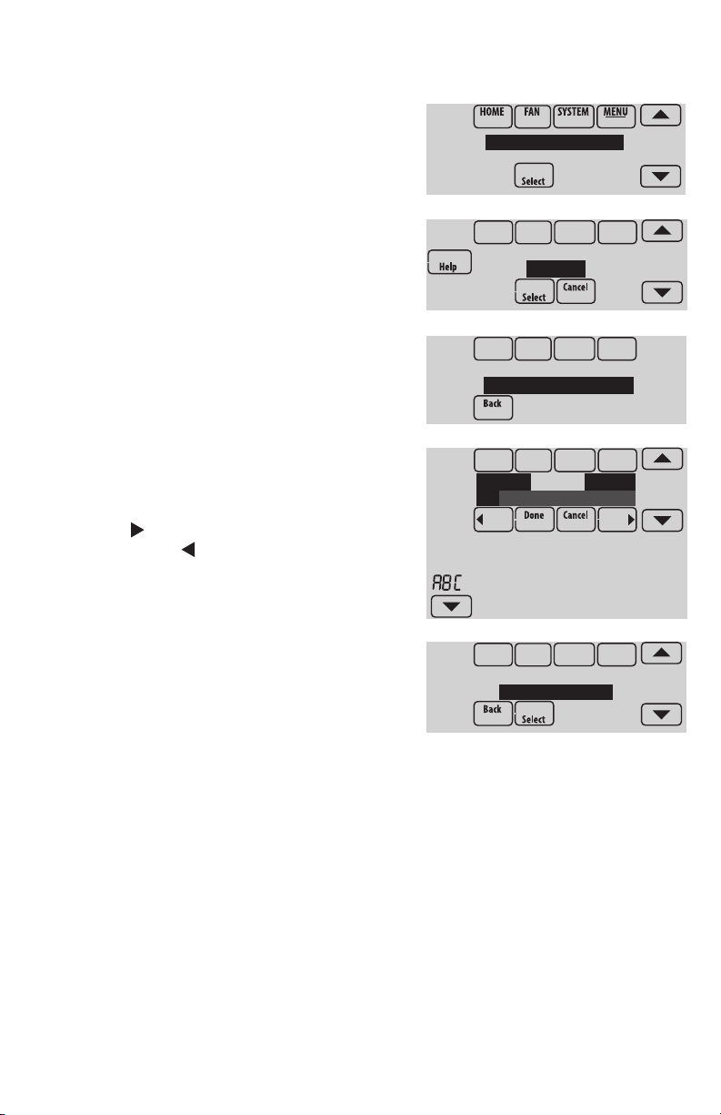
Connecting to Wi-Fi
After installer setup, you will be prompted to connect to a Wi-Fi network.
NOTE: If you select No, the homeowner
can connect to the Wi-Fi network later. (See
“Connecting to Wi-Fi later” on page 10
or in the User’s Guide.) The thermostat will
display its Home screen and thermostat
setup is complete.
Connect to a
Wi-Fi network now?
1 Connect to the Wi-Fi network now.
1.1 Press Yes.
The thermostat will scan for available
Wi-Fi networks.
1.2 Use the arrow buttons to scroll up/
down or left/right. Press the Wi-Fi
network name, then press Select.
NOTE: If the Wi-Fi network name is hidden,
see “Connecting to a hidden Wi-Fi network”
on page 12.
1.3 When prompted, press the screen to
edit the password (if necessary).
1.4 Enter the password.
Press the s or t buttons to change
the letter or number.
Press the button to move to the next
character, or the button to move to
the previous character.
Use the s or t buttons at the bottom
to change letter case.
Press Done when complete.
1.5 The screen will let you know when the
connection is successful. Press Done
when the connection is successful.
If the connection is not successful,
the screen will explain why not. See
“Unsuccessful connection” on page
11. Follow instructions on the screen
to try again.
NOTE: Press the Help button for more
information about an unsuccessful connection.
Finding Networks
Please Wait
Select Wi-Fi Network
Your Network
Enter Password
Press Here to Edit
Delete Space
AC
Connection
Successful
8
Page 9
1-855-733-5465
yourhome.honeywell.com
Honeywell
Golden
M35343A
2 The homeowner must have a Total Connect Comfort account.
2.1 Have the homeowner go to
mytotalconnectcomfort.com and follow
the instructions to login or create an
Register at:
Honeywell.com/TCC
account.
2.2 Press the t button to display MAC
and CRC.
2.3 Note the Thermostat MAC and CRC; they will be needed during registration.
Or, refer to the User’s Guide.
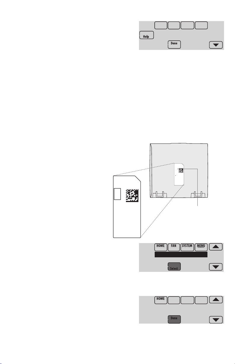
Finding the password (Date Code)
• To make changes to Installer Setup
• To perform an Installer Test
Finding the password
You can find the date code
on the back of the thermostat,
or touch Menu, select Dealer Information,
and scroll to the bottom to see Date Code.
1 Touch Menu.
2 Select Dealer Information.
3 Scroll down to see the Date Code.
RoHs Compliant
Conformité RoHs
Assembled in Mexico
Assemblé au Mexique
1524
Thermostat (back view)
Valley, MN 55422
Dealer Information
Installer Options
TH8321WF1001
Date Code: 1524
RoHs Compliant
Conformité RoHs
Assembled in Mexico
Assemblé au Mexique
1524
1
TH8321WF1001
Residential/Résidentiel
1-800-468-1502
http://yourhome.honeywell.com
Commercial/Commerciale
1-888-245-1051
http://customer.honeywell.com
Honeywell, Golden Valley, MN 55422
Password
(Date Code)
9
Page 10
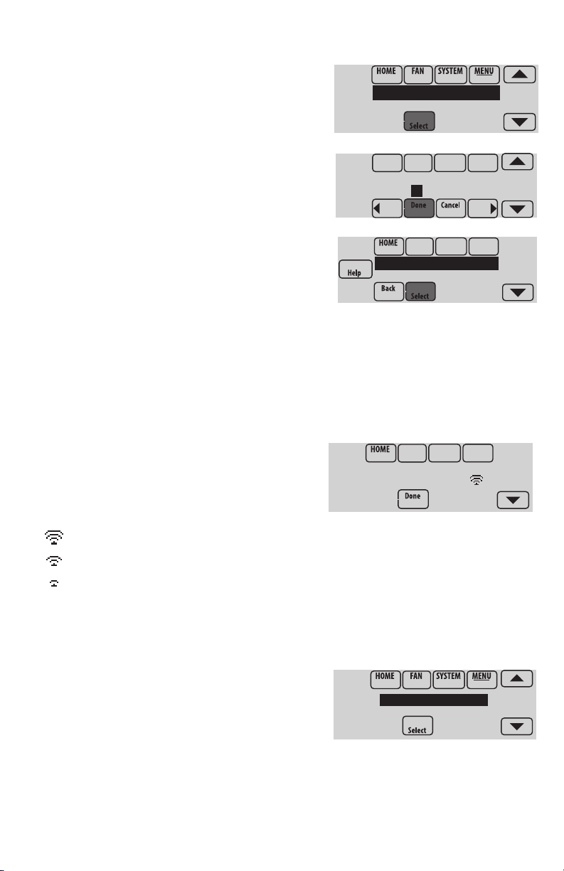
Making changes to Installer Setup and performing an Installer Test
1 Touch Menu.
Installer Options
2 Select Installer Options.
3 Enter password (date code) and
touch Done. See “Finding the password” on
page 9 to find the date code.
4 Select Installer Setup or Installer Test.
5 Follow prompts on the screen to select
the desired setup options or to perform an
equipment test.
Checking signal strength
After you successfully connect to the Wi-Fi
network (see “Connecting to Wi-Fi” step 1.5),
the thermostat will display signal strength. The
signal strength symbols have the following
meanings:
Signal strength is 75%–100%
Signal strength is 50%–75%
Signal strength is 0%–50%
Enter password
0 0 0 0
Installer Setup
Installer Test
Wi-Fi Network:
YourNetwork
You can also check signal strength at any time after the thermostat is connected to the
Wi-Fi network by pressing MENU then Wi-Fi Setup.
Connecting to Wi-Fi later
1 Press MENU, then Wi-Fi Setup.
2 Follow the prompts on-screen (and in
“Connecting to Wi-Fi”) to select the Wi-Fi
network and enter the password.
NOTE: To view and set the Wi-Fi thermostat
remotely, the homeowner must have a Total
Connect Comfort account. See “Connecting to
Wi-Fi” step 2.
10
DoaIol Inrol Madorl
Wi-Fi Setup
Installer Options
Page 11

Unsuccessful connection
If you are unsuccessful in connecting the thermostat to the Wi-Fi network, you will
see a Connection Failed screen. Press the t button for other tips about this failed
connection. Here are three specific reasons the connection might be unsuccessful.
For all Connection Failed screens, pressing Done will return to the Menu screen.
Invalid Password
The password you entered is invalid. Check that you have the right password and try
again.
Press Done to return to “Connecting to Wi-Fi” step 1.3 on page 8.
No IP Address
The thermostat was unable to obtain an IP address from the router. Verify the router is
correctly set up to automatically assign IP addresses. This connection can take several
minutes. If there is still no connection, remove the thermostat from the wallplate for 10
seconds, then snap it back into place.
No Internet Link
The thermostat connected to the Wi-Fi network but was unable to establish a
connection to the internet. Check the router settings and try again. Make sure the
Ethernet cable is plugged into the router and try rebooting the router if necessary.
11
Page 12
Connecting to a hidden Wi-Fi network
If the Wi-Fi network name is hidden and it doesn’t show up in the list in “Connecting to
Wi-Fi” follow these steps to connect to it.
1 Press MENU, then Wi-Fi Setup.
DoaIol Inrol Madorl
Wi-Fi Setup
Installer Options
2 Press Other, then press Select.
3 When prompted, press the screen to edit the
network name.
4 Enter the network name.
Press the s or t buttons to change the letter
or number.
Press the button to move to the next
character, or the button to move to the
previous character.
Use the s or t buttons at the bottom to
change letter case.
Press Done when complete.
5 Select the appropriate network security setting,
then press Select.
6 Enter the Wi-Fi network password as shown in
“Connecting to Wi-Fi” step 1.4.
WirelessNetwork
Other...
Enter Network Name
Press Here to Edit
Delete Space
AC
SSID Security
Open Network
12
Page 13
Specifications and replacement parts
Operating Ambient Temperature
Thermostat: 32 to 120° F (0 to 48.9° C)
Operating Relative Humidity
Thermostat: 5% to 90% (non-condensing)
Physical Dimensions (height, width, depth)
Thermostat: 4-15/16 x 4-5/8 x 1-1/8 inches (126 mm x 118 mm x 29 mm)
Wi-Fi Communication
Supports 802.11 B/G/N home wireless router
Frequency: 2.4 Ghz
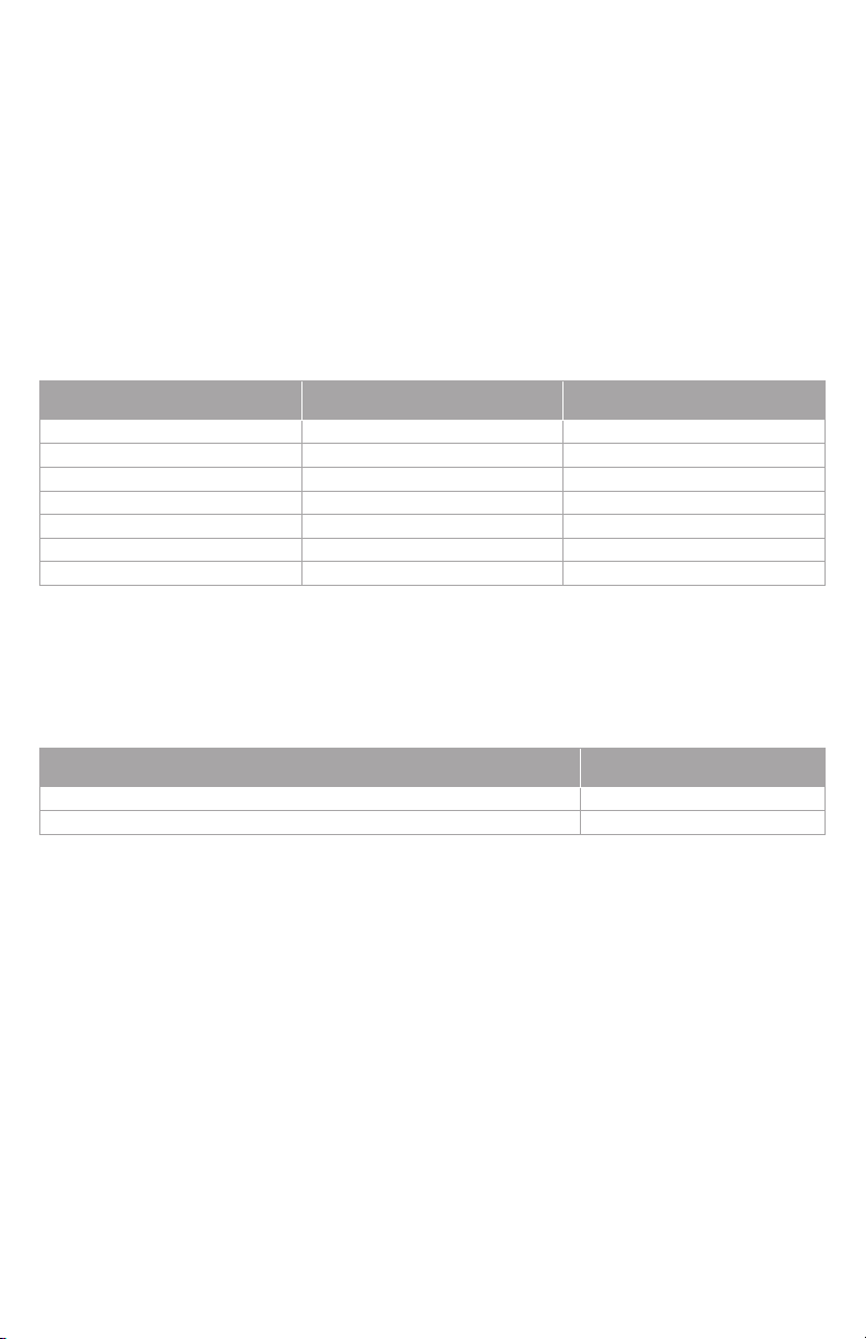
Electrical ratings
Terminal Voltage (50/60 Hz) Max. Current Rating
W - OB 18 to 30 VAC and 750 mVDC 1.00A
Y (cooling) 18 to 30 VAC 1.00A
G (fan) 18 to 30 VAC 0.50A
W2 - Aux (heating) 18 to 30 VAC 0.60A
Y2 (cooling) 18 to 30 VAC 0.60A
A-L/A (output) 18 to 30 VAC 1.00A
U1/U1 30 VAC max. 0.50A
Power Consumption:
Operating voltage: 24 V~
Backlight on: 2.35 VA
Backlight off: 1.40 VA
Accessories and replacement parts
Accessories / Replacement Parts Honeywell Part Number
Cover Plate (covers marks left by old thermostats) THP2400A1019
Wire Saver Module THP9045A1023
13
Page 14

33-00155EFS-01
Feature L-HWLV2-WIFI
Clear Connect®, RedLINK™, or Wi-Fi
Stages
Residential or Commercial
Dual Powered - C Wire or Battery C Wire only
Onboard Humidity Sensor
Number of Universal Relays
Number of Universal Sensor Inputs
Economizer / TOD Output
DISCONNECT POWER BEFORE INSTALLATION. Can cause electrical shock or equipment
damage.
MERCURY NOTICE: If this product is replacing a control that contains mercury in a sealed
tube, do not place the old control in the trash. Contact the Thermostat Recycling Corporation at
www.thermostat-recycle.org or 800-238-8192 for information on how and where to properly and
safely dispose of your old thermostat.
Must be installed by a trained, experience technician. Read these instructions carefully.
Failure to follow these instructions can damage the product or cause a hazardous condition.
Wi-Fi
3H/2C HP
2H/2C CONV
P
P
1
1
P
Technical Assistance | 24 hours a day, 7 days a week | www.lutron.com
U.S.A. / Canada: 1.800.523.9466 | Mexico: +1.888.235.2910
Other Countries: +1.610.282.3800
Lutron Electronics Co., Inc.
7200 Suter Road
Coopersburg, PA 18036-1299
USA
TEL: +1.610.282.3800
FAX: +1.610.282.1243
www.lutron.com
Lutron, , and Clear Connect are registered
trademarks of Lutron Electronics Co., Inc.
© 2015 Honeywell International Inc
33-00155EFS—01 M.S. 12-15
P/N 041-539 Rev. A
Printed in U.S.A.
Automation and Control Systems
Honeywell International Inc.
1985 Douglas Drive North
Golden Valley, MN 55422
http://customer.honeywell.com
Page 15

Wireless Thermostat
Guide d’installation
Référence aux caractéristiques clés
* Le mot de passe est le code de date.
Affichage en cours. L’option soulignée
indique l’affichage courant.
Boutons de contrôle du mode. Utilisés
pour modifier les réglages du ventilateur
ou du chauffage/refroidissement du
système.
Menu. Sélectionnez les options pour :
régler les programmes, voir l’état de
l’équipement, modifier les réglages IAQ,
accéder aux options de l’installateur*, etc.
État en cours. Affiche le mode du
système (chauffage/refroidissement), la
température et l’humidité extérieures.
Programme en cours. Affiche la
température désirée et l’état du
programme.
Conditions intérieures. Affiche la
température et l’humidité intérieures.
Heure actuelle.
Voyant d’alerte. Allumé lorsque
le message d’alerte est actif ou que
le système est réglé sur chauffage
d’urgence (Em Heat).
Page 16

1-855-733-5465
yourhome.honeywell.com
Honeywell
Golden
M35343A
NE PAS JETER
LE MERCURE
ATTENTION : AVIS RELATIF AU RECYCLAGE DU
MERCURE
Ce produit ne contient aucun mercure. Cependant, ce
Hg
produit peut remplacer un produit qui contient du mercure.
Le mercure et les produits contenant du mercure ne
doivent pas être jetés aux ordures ménagères.
Pour obtenir plus d›informations pour savoir comment
et où recycler adéquatement un thermostat contenant
du mercure aux États-Unis, consultez l’organisme
de recyclage des thermostats (Thermostat Recycling
Corporation) à www.thermostat-recycle.org.
Pour le recyclage de thermostats contenant du mercure au
Canada, consultez l’organisme Switch the Stat à
www.switchthestat.ca
Pour commencer
Suivez ces étapes de base pour installer le
thermostat, configurer les options de l’installateur
et vous connecter au réseau Wi-Fi.
REMARQUE : For the product specifications,
please go to www.lutron.com
Thermostat (vue arrière)
RoHs Compliant
Conformité RoHs
Assembled in Mexico
Assemblé au Mexique
1524
1
TH8321WF1001
Residential/Résidentiel
1-800-468-1502
http://yourhome.honeywell.com
Commercial/Commerciale
1-888-245-1051
http://customer.honeywell.com
Honeywell, Golden Valley, MN 55422
Installation du thermostat
3 Séparez la plaque murale du
thermostat.
Appuyez sur le bouton supérieur et tirez
pour retirer la plaque murale.
2
RoHs Compliant
Conformité RoHs
Assembled in Mexico
Assemblé au Mexique
1524
Bouton
Mot de passe
(code de date)
Valley, MN 55422
Thermostat
Plaque murale
(vue arrière)
Page 17

CONVENTIONNELLE
4 Montez la plaque murale comme
illustré.
Montez la nouvelle plaque murale
à l’aide des vis et ancres fournies
avec le thermostat.
Percez des trous de 3/16 po
pour les cloisons sèches.
Percez des trous de 7/32 po
pour le plâtre.
5 Branchez l’alimentation.
Une alimentation de 24 V c.a. est
requise. Branchez le côté commun
du transformateur à la borne C.
Plaque
murale
C
K
RC
R
U1
U1
U2
U2
C
K
C
R
R
U1
U1
U2
U2
THERMOPOMPE
S1
S1
S1
S1
W
O/B
Y
Y
G
G
AUX
W2
-E
Y2
Y2
L/A
A
S1
S1
S1
S1
O/B
W
Y
Y
G
G
AUX
W2
-E
Y2
Y2
A
L/A
6 Câblez le thermostat.
Consultez le tableau et les schémas
de câblage à la page suivante.
a Mettez l’alimentation 24 V c.a. en
marche MAINTENANT. 24 V c.a.
(fil C) sont requis.
7 Montez le thermostat sur la
plaque murale.
Alignez le thermostat en bas et
enclenchez-le en place comme
illustré.
3
Thermostat
CONVENTIONNELLE
C
K
RC
R
U1
U1
U2
U2
THERMOPOMPE
Plaque murale
S1
S1
S1
S1
O/B
W
Y
Y
G
G
AUX
W2
-E
Y2
Y2
A
L/A
Page 18

TRANSFORMATEUR
1
2
TRANSFORMATEUR
TRANSFORMATEUR
Désignations des bornes
Système conventionnel Thermopompe
Borne Description Borne Description
U1 / U1
S1 / S1
* Retirez le cavalier installé en usine uniquement pour les systèmes à deux transformateurs.
** Le module économiseur de fils THP9045A1023 est utilisé sur les systèmes de chauffage/refroidissement lorsque vous n’avez
que quatre fils sur le thermostat et qu’un cinquième fil commun est requis. Utilisez la borne K à la place des bornes Y et G sur les
systèmes conventionnels ou à thermopompe pour assurer le contrôle du ventilateur et du compresseur par un fil unique—le fil non
utilisé devient alors le fil commun. Voir les instructions du THP9045 pour plus d’informations.
Fil commun du côté secondaire du
C
transformateur de climatisation (pour 2
transformateurs).
Fil commun du côté secondaire du
C
transformateur de refroidissement.
Rc* Alimentation refroidissement. Rc Alimentation refroidissement.
R* Alimentation chauffage. R Alimentation chauffage.
W Chauffage étage 1 O/B
W2 Chauffage étage 2 AUX-E
Vanne de commutation pour les
thermopompes.
Chauffage de secours/Chauffage
d’urgence
Y Compresseur étage 1 Y Compresseur étage 1
Y2 Compresseur étage 2 Y2 Compresseur étage 2
G Relais de ventilateur G Relais de ventilateur
Branchez au module d’économiseur ou
A
au panneau d’éclairage (heure du jour).
Relais universel pour l’humidification, la
déshumidification, la ventilation ou un
étage de chauffage/refroidissement.
Entrée universelle pour un capteur
d’intérieur, d’extérieur ou de soufflage
câblé.
Branchez à la borne K sur le module
K**
économiseur de fils.
U1 / U1
S1 / S1
Branchez au moniteur du compresseur,
au panneau de zone, au module
L/A
d’économiseur ou au panneau d’éclairage
(heure du jour).
Relais universel pour l’humidification, la
déshumidification, la ventilation ou un
étage de chauffage/refroidissement.
Entrée universelle pour un capteur
d’intérieur, d’extérieur ou de soufflage
câblé.
Branchez à la borne K sur le module
K**
économiseur de fils.
HUMIDIFICATEUR, DÉSHUMIDIFICATEUR OU VENTILATEUR
ÉLECTRIQUE
THERMOSTAT
C
K
C
R
R
HUMIDIFICATEUR,
U1
DÉSHUMIDIFICATEUR
OU VENTILATEUR
U1
DÉSHUMIDIFICATION AVEC VENTILATEUR BASSE VITESSE
1
OU
ÉLECTRIQUE
THERMOSTAT
C
K
R
C
CAVALIER INSTALLÉ SUR
R
SITE ENTRE R ET U11
U1
U1
Câblez le relais universel du thermostat sur la vitesse de
ventilateur basse pour la commande de déshumidication sur
l’équipement. Le relais du thermostat peut être réglé sur nor-
malement ouvert ou normalement fermé dans la conguration
de l’installateur du thermostat.
Contacts secs normalement ouverts
DU SYSTÈME
C
24
120 V c.a.
V c.a.
R
TRANSFORMATEUR
D'HUMIDIFICATEUR,
DÉSHUMIDIFICATEUR,
24
V c.a.
C
24
V c.a.
R
DÉSHUMIDIFICATION
AVEC VENTILATEUR
BASSE VITESSE
VENTILATION
120 V c.a.
DU SYSTÈME
120
V c.a.
Contacts secs normalement fermés
4
HUMIDIFICATEUR, DÉSHUMIDIFICATEUR OU VENTILATEUR NON
ÉLECTRIQUE
THERMOSTAT
C
K
R
C
CAVALIER INSTALLÉ SUR
R
SITE ENTRE R ET U1
U1
HUMIDIFICATEUR,
DÉSHUMIDIFICATEUR
U1
OU VENTILATEUR NON
ÉLECTRIQUE
CONNEXION D’UN ÉTAGE DE CHAUFFAGE OU REFROIDISSEMENT
À U1
THERMOSTAT
C
K
R
C
R
1
2
U1
U1
Les bornes U1 sont des contacts secs normalement
1
ouverts lorsque le système est conguré pour un étage
de chauffage ou de refroidissement.
Un cavalier doit être installé si l’étage de chauffage ou
de refroidissement est alimenté par le transformateur
du système. N’installez PAS de cavalier si l’étage de
chauffage a son propre transformateur.
CHAUFFAGE ÉTAGE 3,
REFROIDISSEMENT ÉTAGE 3,
CHAUFFAGE SECOURS ÉTAGE 2
POUR THERMOPOMPES OU
CHAUFFAGE RAYONNANT
GÉOTHERMIQUE
C
V c.a.
R
TRANSFORMATEUR
C
24
V c.a.
R
DU SYSTÈME
24
DU SYSTÈME
V c.a.
120
V c.a.
120
Page 19

Effectuer la configuration de l’installateur
Les options de configuration définissent le type de système que vous installez et les
préférences d’affichage.
1 Suivez les invites sur l’écran pour sélectionner les options appropriées.
Sur les écrans affichés, vous verrez les options permettant de définir les
points suivants :
1.6 L’application (résidentielle ou
commerciale).
APPLICATION
residential
1.7 Le nom du thermostat, qui vous
permettra de l’identifier si vous
installez plus d’un thermostat (pour
THERMOSTAT NAME
THERMOSTAT
une application de CVCA à zones, par
exemple).
1.8 Le type de thermostat, programmable
ou non, en fonction de vos préférences.
THERMOSTAT TYPE
programmable
1.9 L’échelle de température, Fahrenheit ou
Celsius.
TEMPERATURE SCALE
fahrenheit
1.10 Utiliser la température extérieure
REMARQUE : Choisissez WIRED/INTERNET
USE OUTDOOR TEMP
wired / internet
(Câblé/Capteur) si votre application nécessite
un capteur câblé, ou si elle utilisera Internet
pour obtenir les informations météo.
1.11 Le type de système de chauffage.
1.12 Pour toutes les options de l’installateur,
HEATING SYSTEM
conv. forced air
appuyez sur les boutons s ou t pour
modifier l’option.
1.13 Appuyez sur Next (Suivant) pour passer au réglage suivant, et sur Done
(Terminé) une fois que la configuration est terminée.
5
Page 20

Câblage
1C/1CL (1 transformateur)
Rc Alimentation [1]
R [R + Rc reliés par cavalier]
W Relais chauffage
Y Contacteur compresseur
G Relais ventilateur
C Neutre 24Vca
S1 Capteur en option
Chauffage seulement
Rc Alimentation [1]
R [R + Rc reliés par cavalier]
W Relais chauffage
C Neutre 24Vca
S1 Capteur en option
Chauffage seulement (Série 20)
Rc [R + Rc reliés par cavalier]
R Borne « R » valve Série 20 [1]
W Borne « B » valve Série 20
Y Borne « W » Série 20
C Neutre 24Vca
S1 Capteur en option
2C/2CL (1 transformateur)
Y2 Relais climatisation 2
W2 Relais chauffage 2
Rc Alimentation [1]
R [R + Rc reliés par cavalier]
W Relais chauffage
Y Relais climatisation 1
G Relais ventilateur
C Neutre 24Vca
S1 Capteur en option
1C/1CL (2 transformateurs)
Rc Alimentation (climatisation) [1, 2]
R Alimentation (chauffage) [1, 2]
W Relais chauffage
Y Contacteur compresseur
G Relais ventilateur
C Neutre 24Vca [3]
S1 Capteur en option
Chauffage seulement avec ventilateur
Rc Alimentation [1]
R [R + Rc reliés par cavalier]
W Relais chauffage
G Relais ventilateur
C Neutre 24Vca [3]
S1 Capteur en option
Climatisation seulement
Rc Alimentation [1]
R [R + Rc reliés par cavalier]
Y Contacteur compresseur
G Relais ventilateur
C Neutre 24Vca
S1 Capteur en option
2C/2CL (2 transformateurs)
Y2 Relais climatisation 2
W2 Relais chauffage 2
Rc Alimentation (climatisation) [1, 2]
R Alimentation (chauffage) [1, 2]
W Relais chauffage 1
Y Relais climatisation 1
G Relais ventilateur
C Neutre 24Vca [3
S1 Capteur en option
Voir [remarques] ci-dessous
[1] Alimentation. Fournir un moyen de disjoncter et une protection contre les surcharges
si nécessaire.
[2] Retirez le cavalier pour les installations à 2 transformateurs.
[3] La connexion commune doit parvenir du transformateur de refroidissement en cas d’installation à 2
transformateurs.
6
Page 21

Câblage
Thermopompe 1C/1CL
(pas de chauffage auxiliaire)
Rc Alimentation [1]
R [R + Rc reliés par cavalier]
O/B Valve d’inversion [4]
Y Contacteur compresseur
G Relais ventilateur
C Neutre 24Vca
S1 Capteur en option
Thermopompe 2C/1CL
(avec chauffage auxiliaire)
L Disp. surveillance équipement [5]
Aux/E Relais auxiliaire de chauffage (chauffage
2) / de chauffage d’urgence
Rc Alimentation [1]
R [R + Rc reliés par cavalier]
O/B Valve d’inversion [4]
Y Contacteur compresseur
G Relais ventilateur
C Neutre 24Vca
S1 Capteur en option
Thermopompe 2C/2CL
(pas de chauffage auxiliaire)
Y2 Relais compresseur 2
Rc Alimentation [1]
R [R + Rc reliés par cavalier]
O/B Valve d’inversion [4]
Y Relais compresseur 1
G Relais ventilateur
C Neutre 24Vca
S1 Capteur en option
Thermopompe 3C/2CL
(avec chauffage auxiliaire)
Y2 Relais compresseur 2
L Disp. surveillance équipement [5]
Aux/E Relais auxiliaire de chauffage (chauffage
2) / de chauffage d’urgence
Rc Alimentation [1]
R [R + Rc reliés par cavalier]
O/B Valve d’inversion [4]
Y Relais compresseur 1
G Relais ventilateur
C Neutre 24Vca
S1 Capteur en option
Voir [remarques] ci-dessous
[1] Alimentation. Fournir un moyen de disjoncter et une protection contre les surcharges
si nécessaire.
[4] O/B configurés pour commander comme O ou B dans la configuration d’installation.
[5] Thermopompe rénclenchée (continuellement alimentée lorsque le thermostat est réglé sur
Em. Heat ; surveillance installation lorsque configuré pour chauffage, climatisation ou arrêt).
7
Page 22

Connexion au réseau Wi-Fi
Après avoir réalisé la configuration de l’installateur, vous serez invité à vous connecter
à un réseau Wi-Fi.
REMARQUE : Si vous sélectionnez No
(Non), le propriétaire pourra se connecter
ultérieurement au réseau Wi-Fi. (Voir
« Connexion ultérieure au réseau Wi-Fi »
à la page 10 ou dans le Guide de
l’utilisateur.) Le thermostat affiche son écran
d’accueil et la configuration du thermostat
est terminée.
1 Connectez-vous maintenant au réseau
Wi-Fi.
1.1 Appuyez sur Yes (Oui). Le thermostat
détecte les réseaux Wi-Fi disponibles.
1.2 Utilisez les boutons fléchés pour
défiler vers le haut/bas ou à gauche/
droite. Appuyez sur le nom du réseau
Wi-Fi, puis sur Select (Sélectionner).
REMARQUE : Si le nom du réseau Wi-Fi
est masqué, consultez « Connexion à un
réseau Wi-Fi masqué » à la page 12.
1.3 À l’invite, appuyez sur l’écran
pour modifier le mot de passe (si
nécessaire).
1.4 Inscrivez le mot de passe.
Appuyez sur les boutons s ou t pour
modifier la lettre ou le chiffre.
Appuyez sur le bouton pour passer
au caractère suivant, ou sur le bouton
pour passer au caractère précédent.
Utilisez les boutons s ou t en bas
pour modifier la casse de la lettre.
Appuyez sur Done (Terminé) lorsque
vous avez terminé.
1.5 L’écran indique si la connexion a
réussi. Appuyez sur Done (Terminé)
lorsque la connexion a réussi. Si la
connexion a échoué, l’écran indique la
raison de l’échec. Voir « Échec de la connexion » à la page 11. Suivez les
instructions à l’écran pour essayer de nouveau.
REMARQUE : Appuyez sur le bouton Help (Aide) pour obtenir plus d’informations
sur l’échec de la connexion.
Connect to a
Wi-Fi network now?
Finding Networks
Please Wait
Select Wi-Fi Network
Your Network
Enter Password
Press Here to Edit
Delete Space
AC
Connection
Successful
8
Page 23

TH8321WF1001
Date Code: 1524
1-855-733-5465
yourhome.honeywell.com
Honeywell
Golden
M35343A
2 Le propriétaire doit posséder un compte Total Connect Comfort.
2.4 Demandez au propriétaire de se
rendre à mytotalconnectcomfort.com et
Register at:
de suivre les instructions de connexion
ou de création de compte.
2.5 Appuyez le bouton t pour afficher la
MAC et CRC.
2.6 Notez l’adresse MAC et CRC du thermostat; elles seront nécessaires durant
l’inscription. Ou, référez-vous au Guide de l’utilisateur.
Trouvez le mot de passe (code de date)
• Pour modifier la Configuration de l’installateur
• Pour effectuer un Test de l’installateur
Trouvez le mot de passe
Vous pouvez trouver le code de date
au dos du thermostat, ou touchez Menu,
sélectionnez Dealer Information, et faites
défiler pour voir le code de date.
1 Touchez Menu.
RoHs Compliant
Conformité RoHs
Assembled in Mexico
Assemblé au Mexique
1524
Thermostat (vue arrière)
RoHs Compliant
Conformité RoHs
Assembled in Mexico
Assemblé au Mexique
1524
1
TH8321WF1001
Residential/Résidentiel
1-800-468-1502
http://yourhome.honeywell.com
Commercial/Commerciale
1-888-245-1051
http://customer.honeywell.com
Honeywell, Golden Valley, MN 55422
Mot de passe
(code de date)
2 Sélectionnez Dealer Information
(Coordonnées du distributeur).
3 Faites défiler pour voir le code de date.
9
Valley, MN 55422
Dealer Information
Installer Options
Page 24

Modification du réglage de l’installateur et réalisation du test de
l’installateur
1 Touchez Menu.
2 Sélectionnez Installer Options (Options de
l’installateur).
3 Entrez le mot de passe (code de date)
et touchez Done (Terminé). Consultez la
rubrique « Trouvez le mot de passe » à la
page 9 pour trouver le code de date.
4 Sélectionnez Installer Setup (Configuration
de l’installateur) ou Installer Test (Test de
l’installateur).
5 Suivez les invites à l’écran pour
sélectionner les options de réglage
désirées ou pour effectuer un test de
l’équipement.
Installer Options
Enter password
0 0 0 0
Installer Setup
Installer Test
Vérification de la puissance du signal
Une fois la connexion au réseau Wi-Fi établie
(voir l’étape 1.5 de la section « Connexion
au réseau Wi-Fi »), le thermostat affichera
la puissance du signal. Les symboles de
puissance du signal ont les significations
suivantes :
Wi-Fi Network:
YourNetwork
La puissance du signal est de 75 % – 100 %.
La puissance du signal est de 50 % – 75 %.
La puissance du signal est de 0 % – 50 %.
Vous pouvez également contrôler la puissance du signal à tout moment une fois que
le thermostat est connecté au réseau Wi-Fi en appuyant sur MENU puis sur Wi-Fi Setup
(Configuration Wi-Fi).
Connexion ultérieure au réseau Wi-Fi
1 Appuyez sur MENU, puis sur Wi-Fi Setup
(Configuration Wi-Fi).
2 Suivez les invites qui s’affichent (et les
instructions de la section « Connexion au
réseau Wi-Fi ») pour sélectionner le réseau
Wi-Fi et entrez le mot de passe.
REMARQUE : Pour visualiser et régler le
thermostat Wi-Fi à distance, le propriétaire doit
posséder un compte Total Connect Comfort. Voir
l’étape 2 de la section « Connexion au réseau Wi-Fi ».
10
DoaIol Inrol Madorl
Wi-Fi Setup
Installer Options
Page 25

Échec de la connexion
Si vous n’avez pas réussi à connecter le thermostat au réseau Wi-Fi, l’écran
Connection Failed (Échec de la connexion) s’affiche. Appuyez sur le bouton t pour
obtenir d’autres conseils sur l’échec de la connexion. Les trois raisons principales
pouvant avoir causé l’échec de la connexion sont les suivantes.
Pour tous les écrans d’échec de la connexion, appuyez sur Done (Terminé) si vous
souhaitez revenir à l’écran Menu.
Mot de passe non valide
Le mot de passe entré n’est pas valide. Vérifiez que vous avez le mot de passe correct
et essayez de nouveau.
Appuyez sur Done (Terminé) pour revenir à l’étape 1.3 de la section « Connexion au
réseau Wi-Fi » à la page 6.
Pas d’adresse IP
Le thermostat n’a pas pu obtenir une adresse IP du routeur. Vérifiez que le routeur
est correctement configuré pour assigner automatiquement des adresses IP. Cette
connexion peut prendre plusieurs minutes. S’il n’y a toujours pas de connexion, retirez
le thermostat de la plaque murale pendant 10 secondes et réenclenchez-le.
Pas de connexion à Internet
Le thermostat est connecté au réseau Wi-Fi mais une connexion à Internet n’a pas
pu être établie. Vérifiez les réglages du routeur et essayez de nouveau. Vérifiez que le
câble Ethernet est branché dans le routeur et relancez le routeur si nécessaire.
11
Page 26

Connexion à un réseau Wi-Fi masqué
Si le nom du réseau Wi-Fi est masqué et ne s’affiche pas dans la liste dans « Connexion
au réseau Wi-Fi », suivez ces étapes pour établir la connexion.
1 Appuyez sur MENU, puis sur Wi-Fi Setup
(Configuration Wi-Fi).
2 Appuyez sur Other (Autre) puis sur Select
(Sélectionner).
3 À l’invite, appuyez sur l’écran pour modifier le
nom du réseau.
4 Entrez le nom du réseau.
Appuyez sur les boutons s ou t pour modifier
la lettre ou le chiffre.
Appuyez sur le bouton pour passer au
caractère suivant, ou sur le bouton pour
passer au caractère précédent.
Utilisez les boutons s ou t en bas pour
modifier la casse de la lettre.
Appuyez sur Done (Terminé) lorsque vous avez
terminé.
5 Sélectionnez le réglage de sécurité du
réseau approprié, puis appuyez sur Select
(Sélectionner).
6 Inscrivez le mot de passe du réseau Wi-Fi
comme indiqué dans l’étape 1.4 de la section
« Connexion au réseau Wi-Fi ».
DoaIol Inrol Madorl
Wi-Fi Setup
Installer Options
WirelessNetwork
Other...
Enter Network Name
Press Here to Edit
Delete Space
AC
SSID Security
Open Network
12
Page 27

Caractéristiques techniques et pièces de rechange
Température ambiante de service
Thermostat : 0 à 48,9 °C (32 à 120 °F)
Humidité relative de service
Thermostat : 5 % à 90 % (sans condensation)
Dimensions (hauteur, largeur, profondeur)
Thermostat : 126 x 118 x 29 mm (4 15/16 x 4 5/8 x 1 1/8 po)
Communication Wi-Fi
Compatible avec le routeur sans fil résidentiel 802.11 B/G/N
Fréquence : 2.4 Ghz
Caractéristiques électriques
Borne Tension (50/60 Hz)
W - OB OB 18 à 30 V c.a. et 750 mV
c.c.
Y (refroidissement) 18 à 30 V c.a. 1,00 A
G (ventilateur) 18 à 30 V c.a. 0,50 A
W2 - Aux. (chauffage) 18 à 30 V c.a. 0,60 A
Y2 (refroidissement) 18 à 30 V c.a. 0,60 A
A-L/A (sortie) 18 à 30 V c.a. 1,00 A
U1/U1 30 V c.a. max. 0,50 A
Power Consumption:
Operating voltage: 24 V~
Backlight on: 2.35 VA
Backlight off: 1.40 VA
Courant de fonctionnement
max.
1,00 A
Accessoires et pièces de rechange
Accessoires / pièces de rechange
Plaque de couvercle (marques de couvercle laissées par les anciens
thermostats)
Module économiseur de fils THP9045A1023
13
Référence de pièce
Hoenywell
THP2400A1019
Page 28

33-00155EFS-01
Caractéristique L-HWLV2-WIFI
Clear Connect®, RedLINK™, ou Wi-Fi
Étages
Résidentiel ou commercial
Double alimentation - fil C ou pile Fil C seulement
Capteur d’humidité intégré
Nombre de relais universels
Nombre d’entrées de capteur universel
Économiseur / Sortie heure du jour
Wi-Fi
3 CH/2 REF TP
2 CH/2 REF CONV
P
P
1
1
P
COUPEZ L’ALIMENTATION ÉLECTRIQUE AVANT DE COMMENCER L’INSTALLATION.
Peut provoquer des chocs électriques ou endommager le matériel.
AVIS RELATIF AU MERCURE : Si ce produit remplace un régulateur contenant du mercure
dans un tube scellé, ne mettez pas l’ancien régulateur à la poubelle. Contactez le Thermostat
Recycling Corporation à www.thermostat-recycle.org ou le 800-238-8192 pour obtenir des
informations sur la façon et l’endroit appropriés pour éliminer votre ancien thermostat.
L’installation doit être faite par un technicien expérimenté ayant reçu la formation
appropriée. Lisez attentivement ces instructions. Le fait de ne pas les suivre risque
d’endommager le produit ou de constituer un danger.
Soutien technique | 24 h/24, 7 jours/7 | www.lutron.com
États-Unis / Canada : 1.800.523.9466 | Mexique : +1.888.235.2910
Autres pays : +1.610.282.3800
Lutron Electronics Co., Inc.
7200 Suter Road
Coopersburg, PA 18036-1299
USA
TÉL : +1.610.282.3800
FAX : +1.610.282.1243
www.lutron.com
Lutron, , et Clear Connect sont des marques de
commerce enregistrées et déposées de Lutron
Electronics Co., Inc.
© 2015 Honeywell International Inc
33-00155EFS—01 M.S. 12-15
P/N 041-539 Rev. A
Imprimé aux États-Unis
Solutions de régulation et
d’automatisation
Honeywell International Inc.
1985 Douglas Drive North
Golden Valley, MN 55422
http://customer.honeywell.com
Page 29

Wireless Thermostat
Configuración
del sistema
Referencia a funciones clave
* La contraseña es el código de fecha.
Pantalla actual. La palabra subrayada
indica la pantalla actual.
Botones de control de modalidad.
Úselos para cambiar configuraciones
de ventilador o sistema de calefacción/
refrigeración.
Menú. Seleccione opciones para:
Configurar programaciones, ver estatus
del equipo, cambiar configuraciones de la
calidad del aire interior (IAQ), acceder a
las opciones del instalador*, etc.
Estatus actual. Muestra la modalidad
del sistema (calefacción/refrigeración),
temperatura y humedad en exteriores.
Programación actual. Muestra la
temperatura deseada y el estatus de la
programación.
Condiciones interiores. Muestra la
temperatura y humedad interiores.
Hora actual.
Luz de alerta. Cuando está
encendida indica que hay un mensaje
de alerta activo o que el sistema está
configurado para Calefacción de
emergencia (Em Heat).
Page 30

1-855-733-5465
yourhome.honeywell.com
Honeywell
Golden
M35343A
MERCURIO
Hg
NO BOTE
ATENCIÓN: AVISO PARA EL RECICLAJE DEL
MERCURIO
Este producto no contiene mercurio. Sin embargo, este
producto puede reemplazar uno que contenga mercurio.
El mercurio y los productos que contengan mercurio no se
deben desechar con los desperdicios domésticos.
Para más información sobre cómo y dónde reciclar
adecuadamente un termostato que contenga mercurio en
los Estados Unidos, consulte con Thermostat Recycling
Corporation en www.thermostat-recycle.org.
Para el reciclaje de termostatos con mercurio en Canadá,
consulte con Switch the Stat en
www.switchthestat.ca
Cómo comenzar
Siga estos sencillos pasos para instalar el
termostato, configurar las opciones del instalador
y conectarse a la red WiFi.
NOTA: For the product specifications, please go
to www.lutron.com
Instalar el termostato
1 Separe la placa de pared del
termostato.
Presione el botón de la parte superior
y hale para retirar la placa de pared.
RoHs Compliant
Conformité RoHs
Assembled in Mexico
Assemblé au Mexique
1524
Botón
Termostato (vista posterior)
RoHs Compliant
Conformité RoHs
Assembled in Mexico
Assemblé au Mexique
1524
1
TH8321WF1001
Residential/Résidentiel
1-800-468-1502
http://yourhome.honeywell.com
Commercial/Commerciale
1-888-245-1051
http://customer.honeywell.com
Honeywell, Golden Valley, MN 55422
Contraseña
(código de
fecha)
Valley, MN 55422
Termostato
2
Placa de pared
(vista posterior)
Page 31

CONVENCIONAL
2 Monte la placa de pared como se
ilustra.
Monte la nueva placa de pared
con los tornillos y tarugos que se
incluyen con el termostato.
Taladre agujeros de 3/16 in
(4.8 mm) en paneles de yeso.
Taladre agujeros de 7/32 in
(5.5 mm) en yeso.
3 Conecte la electricidad.
Se necesita un suministro
eléctrico de 24 V CA. Conecte el
lado común del transformador al
terminal C.
Placa
de pared
C
K
RC
R
U1
U1
U2
U2
S1
C
K
S1
C
R
W
O/B
R
Y
U1
G
U1
U2
U2
AUX
W2
Y2
L/A
A
BOMBA DE CALOR
S1
S1
Y
G
-E
Y2
S1
S1
S1
S1
O/B
W
Y
Y
G
G
AUX
W2
-E
Y2
Y2
A
L/A
4 Cablee el termostato.
Refiérase a la tabla y a los
diagramas de cableado de la página
siguiente.
a Conecte la energía
de 24 V CA AHORA. Se necesita
energía de 24 V CA (cable C).
5 Monte el termostato en la placa
de pared.
Alinee el termostato en la parte
inferior y colóquelo a presión en su
lugar como se ilustra.
3
C
K
RC
R
U1
U1
U2
U2
Termostato
CONVENCIONAL
BOMBA DE CALOR
Placa de pared
S1
S1
S1
S1
O/B
W
Y
Y
G
G
AUX
W2
-E
Y2
Y2
A
L/A
Page 32

TRANSFORMADOR
1
1
Designaciones de los terminales
Sistema convencional Bomba de calor
Terminal Descripción Terminal Descripción
U1 / U1
S1 / S1
* Retire el puente instalado en fábrica para sistemas de dos transformadores.
** El módulo protector de cables THP9045A1023 se utiliza en los sistemas de calefacción/refrigeración que solo tienen cuatro cables
en el termostato y cuando se necesita un quinto cable como cable común. Utilice el terminal K en lugar de los terminales Y y G en
sistemas convencionales o de bomba de calor para proporcionar control del ventilador y del compresor mediante un solo cable—el
cable no utilizado se convierte entonces en su cable común. Consulte las instrucciones del THP9045 para obtener más información.
Cable común procedente del lateral
C
secundario del transformador de
refrigeración (si tiene 2 transformadores).
Cable común procedente del lateral
C
secundario del transformador de
refrigeración.
Rc* Energía de refrigeración. Rc Energía de refrigeración.
R* Energía de calefacción. R Energía de calefacción.
W Etapa 1 de calefacción O/B Válvula de cambio para bombas de calor.
W2 Etapa 2 de calefacción AUX-E
Calefacción de reserva/Calefacción de
emergencia
Y Etapa 1 del compresor Y Etapa 1 del compresor
Y2 Etapa 2 del compresor Y2 Etapa 2 del compresor
G Relé del ventilador G Relé del ventilador
Conectar al módulo economizador o al
A
panel de iluminación (TOD).
Relé universal para humidificación,
deshumidificación, ventilación o una
etapa de calefacción/refrigeración.
Entrada universal para un sensor
cableado interior, exterior o de descarga.
Conectar a K en módulo economizador
K**
de cableado.
U1 / U1
S1 / S1
Conectar al monitor del compresor, al
L/A
panel de zonas, al módulo economizador
o al panel de iluminación (TOD).
Relé universal para humidificación,
deshumidificación, ventilación o una
etapa de calefacción/refrigeración.
Entrada universal para un sensor
cableado interior, exterior o de descarga.
Conectar a K en módulo economizador
K**
de cableado.
HUMIDIFICADOR, DESHUMIDIFICADOR O VENTILADOR
CON CORRIENTE
TERMOSTATO
C
K
R
C
R
HUMIDIFICADOR,
U1
DESHUMIDIFICADOR
O VENTILADOR CON
U1
CORRIENTE
DESHUMIDIFICACIÓN CON VENTILADOR A BAJA
VELOCIDAD
TERMOSTATO
C
K
C
R
PUENTE DE CAMPO
INSTALADO ENTRE R Y U1
R
1
U1
OR
U1
Cablee el relé universal del termostato al ventilador de baja
velocidad para el control de la deshumidicación en el equipo.
El relé del termostato puede congurarse para que esté nor-
malmente abierto o normalmente cerrado cuando el instalador
congura el termostato.
DESHUMIDIFICACIÓN
DEL SISTEMA
C
24
V CA
R
TRANSFORMADOR
DE HUM, DESHUM
24
V CA
TRANSFORMADOR
C
24
V CA
R
CON VENTILADOR A
BAJA VELOCIDAD
O VENT
Contactos secos normalmente abiertos
Contactos secos normalmente cerrados
4
120
V CA
V CA
HUMIDIFICADOR, DESHUMIDIFICADOR O VENTILADOR
SIN CORRIENTE
TERMOSTATO
C
K
R
C
PUENTE INSTALADO EN
CAMPO ENTRE R Y U1
R
HUMIDIFICADOR,
U1
120
CONEXIÓN DE UNA ETAPA DE CALEFACCIÓN O
REFRIGERACIÓN A U1
120
V CA
1
2
DESHUMIDIFICADOR O
VENTILADOR SIN
U1
TERMOSTATO
C
K
R
R
U1
U1
Los terminales U1 son normalmente contactos secos
abiertos cuando se conguran para una etapa de
calefacción o refrigeración.
Debe instalar un puente en campo si la etapa de
calefacción o refrigeración está alimentada por el
transformador del sistema. NO instale un puente
en campo si la etapa de calefacción tiene su propio
transformador.
CORRIENTE
C
2
ETAPA 3 DE CALEFACCIÓN, ETAPA 3 DE
REFRIGERACIÓN, ETAPA 2 DE
CALEFACCIÓN DE RESERVA PARA
BOMBAS DE CALOR O CALEFACCIÓN
RADIANTE GEOTÉRMICA
C
R
C
24
V CA
R
TRANSFORMADOR
DEL SISTEMA
120
24
V CA
V CA
TRANSFORMADOR
120
V CA
Page 33

Efectuando la configuración del instalador
Las opciones de configuración definen el tipo de sistema que está instalando y las
preferencias para la pantalla.
1 Siga las indicaciones en la pantalla para elegir las opciones adecuadas.
En algunas de las pantallas, podrá ver las siguientes opciones:
1.1 Aplicación, puede ser residencial o
comercial.
1.2 Nombre del termostato, lo que le
permitirá identificarlo si instala más de
un termostato (por ejemplo, para una
aplicación zonificada de ventilación,
calefacción y aire acondicionado).
1.3 Tipo de termostato, ya sea programable
o no, según la preferencia.
1.4 Escala de temperatura, que puede
expresarse en Fahrenheit o Celsius.
APPLICATION
residential
THERMOSTAT NAME
THERMOSTAT
THERMOSTAT TYPE
programmable
TEMPERATURE SCALE
fahrenheit
1.5 Use la temperatura exterior.
NOTA: Elija WIRED/INTERNET si su aplicación
requiere un sensor cableado o si utilizará el
USE OUTDOOR TEMP
wired / internet
Internet para los datos de las condiciones
climáticas.
1.6 El tipo de sistema de calefacción.
1.7 En las opciones del instalador, presione
HEATING SYSTEM
conv. forced air
los botones s o t para cambiar de
opción.
1.8 Presione Next (Siguiente) para pasar a la siguiente configuración y Done
(Terminado) cuando haya finalizado la configuración.
5
Page 34

Cableado
Sistema 1H/1C (1 transformador)
Rc Alimentación de energía [1]
R [R+Rc unidos por empalme]
W Retransmisor de calefacción
Y Contactor del compresor
G Retransmisor del ventilador
C 24 VCA Común
S1 Sensor opcional
Sistema sólo calefacción
Rc Alimentación de energía [1]
R [R+Rc unidos por empalme]
W Retransmisor de calefacción
C 24 VCA Común
S1 Sensor opcional
Sistema sólo de calefacción (Serie 20)
Rc [R+Rc unidos por empalme]
R Válvula terminal “R” Serie 20 [1]
W Válvula terminal “B” Serie 20
Y Válvula terminal “W” Serie 20
C 24 VCA Común
S1 Sensor opcional
Sistema 2H/2C (1 transformador)
Y2 Retransmisor de refrigeración
W2 Retransmisor de calefacción 2
Rc Alimentación de energía [1]
R [R+Rc unidos por empalme]
W Retransmisor de calefacción
Y Retransmisor de refrigeración 1
G Retransmisor del ventilador
C 24 VCA Común
S1 Sensor opcional
Sistema 1H/1C (2 transformadores)
Rc Energía (de refrigeración) [1, 2]
R Energía (de calefacción) [1, 2]
W Retransmisor de calefacción
Y Contactor del compresor
G Retransmisor del ventilador
C 24 VCA Común [3]
S1 Sensor opcional
Sistema de sólo calefacción con ventilador
Rc Alimentación de energía [1]
R [R+Rc unidos por empalme]
W Retransmisor de calefacción
G Retransmisor del ventilador
C 24 VCA Común
S1 Sensor opcional
Sistema de sólo refrigeración
Rc Alimentación de energía [1]
R [R+Rc unidos por empalme]
Y Contactor del compresor
G Retransmisor del ventilador
C 24 VCA Común
S1 Sensor opcional
Sistema 2H/2C (2 transformadores)
Y2 Retransmisor de refrigeración 2
W2 Retransmisor de calefacción 2
Rc Energía (de refrigeración) [1, 2]
R Energía (de calefacción) [1, 2]
W Retransmisor de calefacción 1
Y Retransmisor de refrigeración 1
G Retransmisor del ventilador
C 24 VCA Común [3]
S1 Sensor opcional
Ver [notas] a continuación
[1] Alimentación de energía. Provee medios de desconexión y protección contra sobrecarga según se
requiera.
[2] Retirar el empalme en sistemas de 2 transformadores.
[3] La conexión común debe realizarse desde el transformador de refrigeración si se trata de una insta-
lación de 2 transformadores.
6
Page 35

Cableado
1H/1C Bomba de calefacción
(sin calefacción auxiliar)
Rc Alimentación de energía [1]
R [R+Rc unidos por empalme]
O/B Válvula de cambio [4]
Y Retransmisor del compresor
G Retransmisor del ventilador
C 24 VCA Común
S1 Sensor opcional
2H/1C Bomba de calefacción
(con calefacción auxiliar)
L Monitor del equipo [5]
Aux/E Retransmisor auxiliar de calefacción
Retransmisor de calefacción de emergencia
Rc Alimentación de energía [1]
R [R+Rc unidos por empalme]
O/B Válvula de cambio [4]
Y Retransmisor del compresor
G Retransmisor del ventilador
C 24 VCA Común
S1 Sensor opcional
2H/2C Bomba de calefacción
(sin calefacción auxiliar)
Y2 Retransmisor del compresor 2
Rc Alimentación de energía [1]
R [R+Rc unidos por empalme]
O/B Válvula de cambio [4]
Y Retransmisor del compresor 1
G Retransmisor del ventilador
C 24 VCA Común
S1 Sensor opcional
3H/2C Bomba de calefacción
(con calefacción auxiliar)
Y2 Retransmisor del compresor 2
L Monitor del equipo [5]
Aux/E Retransmisor auxiliar de calefacción
Retransmisor de calefacción de emergencia
Rc Alimentación de energía [1]
R [R+Rc unidos por empalme]
O/B Válvula de cambio [4]
Y Retransmisor del compresor 1
G Retransmisor del ventilador
C 24 VCA Común
S1 Sensor opcional
Ver [notas] a continuación
[1] Alimentación de energía. Provee medios de desconexión y protección contra sobrecarga según se
requiera.
[4] O/B ajustado para controlar ya sea O o B en configuración del instalador.
[5] Reajuste de la bomba de calefacción (recibe alimentación de energía cuando el termostato se
ajusta en Em Heat; monitor del sistema cuando se ajusta en Heat, Cool u Off).
7
Page 36

Conexión a la red WiFi
Después de la configuración del instalador, se le indicará que conecte el dispositivo a
una red WiFi.
NOTA: Si selecciona la opción No, podrá
conectarse a la red WiFi en otro momento.
(Consulte “Conectar a WiFi más tarde” en
la página 10 o en la Guía del usuario).
El termostato mostrará la pantalla principal
cuando se complete la configuración del
dispositivo.
1 Se le preguntará si desea conectarse a
una red WiFi ahora.
1.1 Presione Yes (Sí). El termostato
buscará las redes WiFi disponibles.
1.2 Utilice los botones de flecha para
desplazarse hacia arriba/abajo o a la
izquierda/derecha. Presione el nombre
de la red WiFi y, luego, presione Select
(Seleccionar).
NOTA: Si el nombre de la red WiFi se
encuentra oculto, consulte “Conexión a una
red WiFi oculta” en la página 12.
1.3 Cuando se le indique, presione la
pantalla para modificar la contraseña
(si fuera necesario).
1.4 Introduzca la contraseña.
Presione los botones s o t para
cambiar la letra o el número.
Presione el botón para desplazarse
al próximo caracter o el botón para
volver al caracter anterior.
Utilice los botones s o t en la parte
inferior para cambiar a mayúscula o
minúscula.
Presione Done (Terminado) cuando
finalice.
1.5 La pantalla le indicará cuando
se haya establecido la conexión
satisfactoriamente. Presione Done
(Terminado) cuando se haya
establecido la conexión satisfactoriamente. Si no se puede establecer la
conexión, en la pantalla aparecerá la razón. Consulte “Conexión fallida” en la
página 11. Siga las instrucciones que aparecen en la pantalla para volver
a intentarlo.
NOTA: Presione el botón Help (Ayuda) para obtener más información sobre una
conexión fallida.
8
Connect to a
Wi-Fi network now?
Finding Networks
Please Wait
Select Wi-Fi Network
Your Network
Enter Password
Press Here to Edit
Delete Space
AC
Connection
Successful
Page 37

TH8321WF1001
Date Code: 1524
1-855-733-5465
yourhome.honeywell.com
Honeywell
Golden
M35343A
2 El propietario residencial debe tener una cuenta Total Connect Comfort.
2.1 Haga que el propietario residencial
ingrese a mytotalconnectcomfort.com
Register at:
y siga las instrucciones para iniciar la
sesión o crear una cuenta.
2.2 Presione el botón t para mostrar la
MAC y CRC.
2.3 Tome nota del MAC y el CRC del termostato: serán necesarios durante la
inscripción. O consulte la Guía del usuario.
Encontrar la contraseña (Código de fecha)
• Para hacer cambios en la Configuración
del instalador
• Para hacer una Prueba del instalador
Encontrar la contraseña
Puede encontrar el código de fecha en la parte
posterior del termostato, o toque Menu (Menú),
seleccione Dealer Information (Información del
distribuidor), y desplácese hacia abajo para ver
el Código de fecha.
1 Toque Menu (Menú).
2 Seleccione Dealer Information (Información del
distribuidor).
3 Desplácese hacia abajo para ver el Código
de fecha.
RoHs Compliant
Conformité RoHs
Assembled in Mexico
Assemblé au Mexique
1524
Termostato (vista posterior)
RoHs Compliant
Conformité RoHs
Assembled in Mexico
Assemblé au Mexique
1524
1
TH8321WF1001
Residential/Résidentiel
1-800-468-1502
http://yourhome.honeywell.com
Commercial/Commerciale
1-888-245-1051
http://customer.honeywell.com
Honeywell, Golden Valley, MN 55422
Contraseña
(código de
fecha)
Valley, MN 55422
Dealer Information
Installer Options
9
Page 38

Cómo hacer cambios en la Configuración del instalador y efectuar la
Prueba del instalador
1 Toque Menu (Menú).
2 Seleccione Installer Options (Opciones del
Instalador).
3 Ingrese la contraseña (código de fecha)
y toque Done (Terminado). Consulte
“Encontrar la contraseña” en la página
9 para el código de fecha.
4 Seleccione Installer Setup (Configuración
del instalador) o Installer Test (Prueba del
instalador).
5 Siga las instrucciones de la pantalla para
seleccionar las opciones de instalación
deseadas o para efectuar una prueba del
equipo.
Installer Options
Enter password
0 0 0 0
Installer Setup
Installer Test
Verificar la potencia de la señal
Después de haberse conectado
satisfactoriamente a la red WiFi (Consulte
el paso 1.5 “Conexión a la red WiFi” ), el
termostato mostrará la potencia de la señal. Los
símbolos de la potencia de la señal indican lo
siguiente:
Wi-Fi Network:
YourNetwork
La potencia de la señal es de 75 % a 100 %.
La potencia de la señal es de 50 % a 75 %.
La potencia de la señal es de 0 % a 50 %.
También puede verificar la potencia de la señal en cualquier momento después de
conectar el termostato a la señal de WiFi. Para ello, presione la opción MENU (MENÚ)
y, luego, Wi-Fi Setup (Configuración de WiFi).
Conectar a WiFi más tarde
1 Presione MENU (MENÚ) y, luego, Wi-Fi Setup
(Configuración de WiFi).
2 Siga las instrucciones que aparecen en la
pantalla (y en la sección “Conexión a la red
WiFi”) para seleccionar la red WiFi e introducir
la contraseña.
NOTA: Para ver y configurar el termostato con
conexión WiFi de manera remota, el propietario
residencial debe tener una cuenta en Total
Connect Comfort. Consulte el paso 2 de la
10
DoaIol Inrol Madorl
Wi-Fi Setup
Installer Options
Page 39

sección “Conexión a la red WiFi”.
Conexión fallida
Si no logra conectar el termostato a una red WiFi, en la pantalla podrá ver el mensaje
Connection Failed (No se pudo establecer la conexión). Presione el botón t para
obtener otros detalles sobre la conexión fallida. A continuación, le presentamos tres
razones específicas por las que puede haber fallado la conexión.
Cuando en la pantalla aparezca el mensaje Connection Failed (No se pudo establecer
la conexión), presione Done (Terminado) para volver a la pantalla del menú.
La contraseña no es válida
La contraseña que usted ingresó no es válida. Verifique si ingresó la contraseña
correcta y vuelva a intentarlo.
Presione Done (Terminado) para volver al paso 1.3 “Conexión a la red WiFi” en la
página 8.
No se encuentra la dirección IP
El termostato no pudo obtener la dirección IP del enrutador. Verifique que el enrutador
esté configurado correctamente para asignar direcciones IP automáticamente. Esta
conexión puede demorar varios minutos. Si todavía no puede establecerse la conexión,
retire el termostato de la placa para pared durante 10 segundos y, luego, vuelva a
calzarlo en la placa.
No hay conexión a Internet
El termostato pudo conectarse a la red WiFi, pero no se pudo establecer una conexión
a Internet. Revise la configuración del enrutador e inténtelo de nuevo. Asegúrese
de que el cable de Ethernet esté conectado al enrutador y, si es necesario, intente
reiniciando el enrutador.
11
Page 40

Conexión a una red WiFi oculta
Si el nombre de la red WiFi está oculto y no aparece en la lista en “Conexión a la red
WiFi”, siga los pasos a continuación para conectarlo.
1 Presione MENU (MENÚ) y, luego, Wi-Fi Setup
(Configuración de WiFi).
DoaIol Inrol Madorl
Wi-Fi Setup
Installer Options
2 Presione Other (Otras) y, luego, presione Select
(Seleccionar).
3 Cuando se le indique, presione la pantalla para
modificar el nombre de la red.
4 Ingrese el nombre de la red.
Presione los botones s o t para cambiar la
letra o el número.
Presione el botón para desplazarse al
próximo caracter o el botón para volver al
carácter anterior.
Utilice los botones s o t en la parte inferior
para cambiar a mayúscula o minúscula.
Presione Done (Terminado) cuando finalice.
5 Seleccione la configuración de seguridad
de red adecuada y, luego, presione Select
(Seleccionar).
6 Ingrese la contraseña de la red WiFi como se
indica en el paso 1.4 “Conexión a la red WiFi”.
WirelessNetwork
Other...
Enter Network Name
Press Here to Edit
Delete Space
AC
SSID Security
Open Network
12
Page 41

Especificaciones y piezas de repuesto
Temperatura ambiente de funcionamiento
Termostato: de 32 a 120 °F (de 0 a 48.9 °C)
Humedad relativa de funcionamiento
Termostato: de 5% a 90% (sin condensación)
Dimensiones físicas (alto, ancho, profundidad)
Termostato: 4-15/16 x 4-5/8 x 1-1/8 pulgadas (126 mm x 118 mm x 29 mm)
Comunicación mediante WiFi
Compatible con enrutador inalámbrico doméstico 802.11 B/G/N
Frecuencia: 2.4 GHz
Clasificación eléctrica
Terminal Voltaje (50/60 Hz) Máx. capacidad de corriente
W - OB 18 a 30 V CA y 750 mV CD 1.00A
Y (refrigeración) 18 a 30 V CA 1.00A
G (ventilador) 18 a 30 V CA 0.50A
W2 - Aux (calefacción) 18 a 30 V CA 0.60A
Y2 (refrigeración) 18 a 30 V CA 0.60A
A-L/A (salida) 18 a 30 V CA 1.00A
U1/U1 30 V CA máx. 0.50A
Power Consumption:
Operating voltage: 24 V~
Backlight on: 2.35 VA
Backlight off: 1.40 VA
Accesorios y piezas de repuesto
Accesorios / Piezas de repuesto
Placa de cubierta (cubre las marcas que dejan los termostatos
anteriores)
Módulo para ahorro de cable THP9045A1023
13
Número de pieza
Honeywell
THP2400A1019
Page 42

33-00155EFS-01
Características L-HWLV2-WIFI
Clear Connect®, RedLINK™, o Wi-Fi
Etapas
Residencial o comercial
Dos tipos de alimentación: cable C o baterías Solo cable C
Sensor de humedad integrado
Cantidad de relés universales
Cantidad de entradas de sensor universales
Salida del Economizador / TOD
DESCONECTE LA ELECTRICIDAD ANTES DE LA INSTALACIÓN. Puede causar descargas
eléctricas o daños al equipo.
AVISO SOBRE MERCURIO: Si este producto está reemplazando a un control que contiene
mercurio en un tubo sellado, no tire a la basura el control anterior. Comuníquese con
Thermostat Recycling. Corporation en www.thermostat-recycle.org o al 800-238-8192 para
obtener información sobre cómo y dónde desechar el termostato de manera adecuada y
segura.
Deberá ser instalado por un técnico capacitado y experimentado. Lea detenidamente estas
instrucciones. De no seguirlas, se podría dañar el producto o provocar una situación peligrosa.
Wi-Fi
BC 3C/2R
CONV 2C/2R
P
P
1
1
P
Asistencia técnica | 24 horas al día, 7 días a la semana | www.lutron.com
EE.UU. / Canadá: 1.800.523.9466 | México: +1.888.235.2910
Otros países: +1.610.282.3800
Lutron Electronics Co., Inc.
7200 Suter Road
Coopersburg, PA 18036-1299
USA
TEL: +1.610.282.3800
FAX: +1.610.282.1243
www.lutron.com
Lutron, , y Clear Connect son marcas registradas
de Lutron Electronics Co., Inc.
© 2015 Honeywell International Inc
33-00155EFS—01 M.S. 12-15
P/N 041-539 Rev. A
Impreso en EE. UU.
Automatización y control desenlace
Honeywell International Inc.
1985 Douglas Drive North
Golden Valley, MN 55422
http://customer.honeywell.com
 Loading...