

Page 1
Switching / 0 – 10 V Power Module Switching / 0 – 10 V Fixture Controller
1
LQSE-4
369610c 1 01.09.24
Power Module
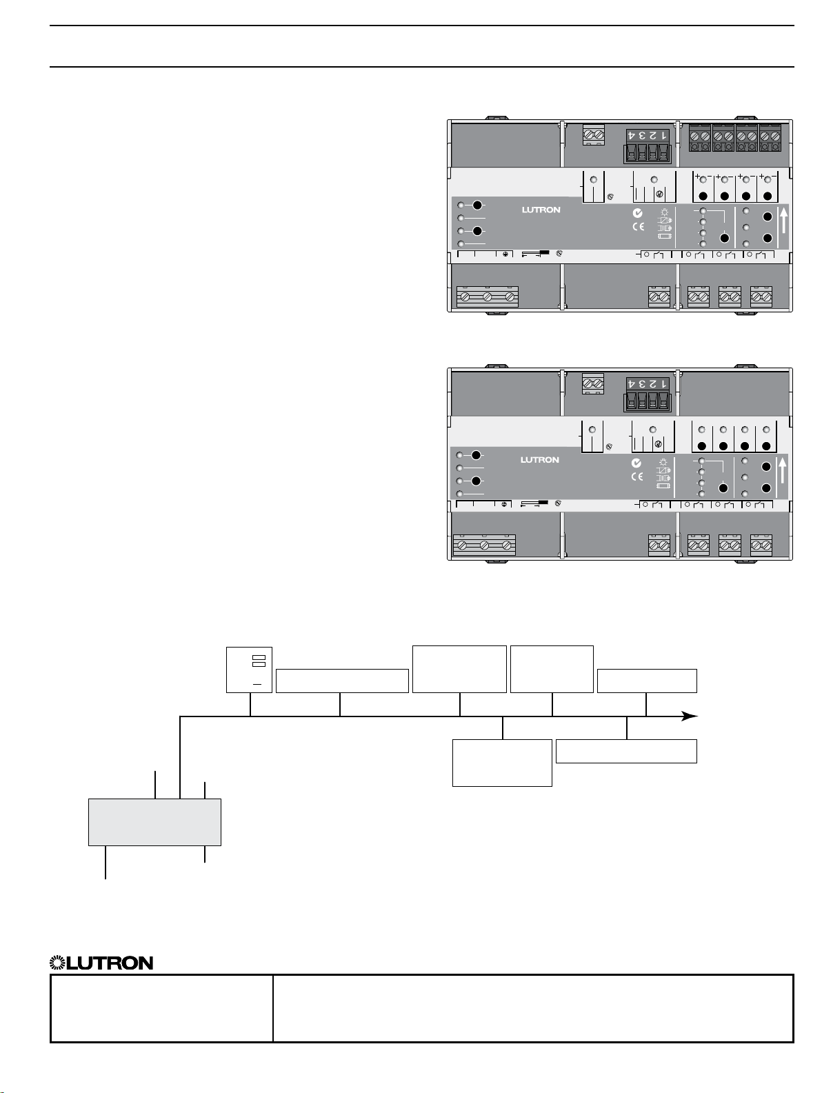
The Power Module family is a group of modular
products for the control of lighting loads. This
document describes the following products:
• Model Number LQSE-4S10-D: Power Module unit
for Switching only
• Model Number LQSE-4T10-D: Power Module unit for
0 –10 V/Switching
Features
• Includes QS link for seamless connection to a
HomeWorks QS system.
• Power Module units can be used in a HomeWorks
QS system to control and manage light in an entire
home or building.
Input
Hi Temp
Program
Power
L
N
LQSE- 4T10-D
0-10 V Power Module
LQSE-4T10-D
230 V~ 50/60 Hz 50 mA
www.lutron.com +44.(0)20.7680.4481
8 mm
CCI
1,2 N•m
Outputs 230 V~ 10 AX each
Mains Only
QS
0,5 N•m
All Others
COM
CCI
MUX
MUX
Z096
µ
1 2
Zone 1Zone 2Zone 3Zone 4
Zones
0-10 V50 mA
COM
Def
Opt1
Option
Opt2
Opt3
3
4
H
M
Up
L
System Example
HomeWorks QS
Contact Closure Input
Switchin g/0 –10 V
Power Module
Wallstation
QS Link
Four 0 –10 V outputs (zones 1– 4)
(model LQSE-4T10-D only)
Power Module
Input
Hi Temp
Program
Power
L
N
LQSE- 4S10- D
HomeWorks QS
Processor
Sivoia QS
Shades/Draperies
CCI
Switching Power Module
LQSE-4S10-D
230 V~ 50/60 Hz 50 mA
www.lutron.com +44.(0)20.7680.4481
1,2 N•m
Outputs 230 V~ 10 AX each
Mains Only
8 mm
QS
Contact Closure
Interface
QS Power Supply
QS
0,5 N•m
All Others
COM
CCI
µ
GRAFIK Eye QS
MUX
MUX
Z096
1 2
Zone 1Zone 2Zone 3Zone 4
COM
Def
Opt1
Option
Opt2
Opt3
3
Up to 100 total
QS devices
H
M
Up
L
4
Four switched outputs, 10 AX each (zones 1– 4)
230 V~ Control Power
SPECIFICATION SUBMITTAL Page
Job Name: Model Numbers:
Job Number:
Page 2

Switching / 0 – 10 V Power Module Switching / 0 – 10 V Fixture Controller
2
LQSE-4
369610c 2 01.09.24
Specifications
Power
• 230 V~ 50/60 Hz
• Lightning strike protection meets ANSI/IEEE standard
62.31–1980. Can withstand voltage surges of up to
6 000 V~ and current surges of up to 3 000 A.
• Current draw: 50 mA max
• Standby power : 1 W
• BTUs/hour when fully loaded: 4
Standards
• IEC/EN 60669-2-1, EN50428
• Lutron Quality Systems registered to ISO 9001:2008
• CE
• C-Tick S
Environment
• Ambient Temperature Operating Range (inside
mounting panel): 0 ºC to 40 ºC
• Calibration point maximum: 65 ºC
• Relative humidity: less than 90% non-condensing
• For indoor use only
Terminals
2
• Mains wiring: 0.5 mm
to 6.0 mm
• 0 –10 V Wiring: 0.5 mm2 to 2.5 mm
• CCI Wiring: 0.5 mm2 to 6.0 mm
• Zone wiring: 0.5 mm2 to 6.0 mm
2
2
2
2
Mounting
• Use an IP20 (minimum) rated consumer panel or
breaker panel with integrated DIN rail
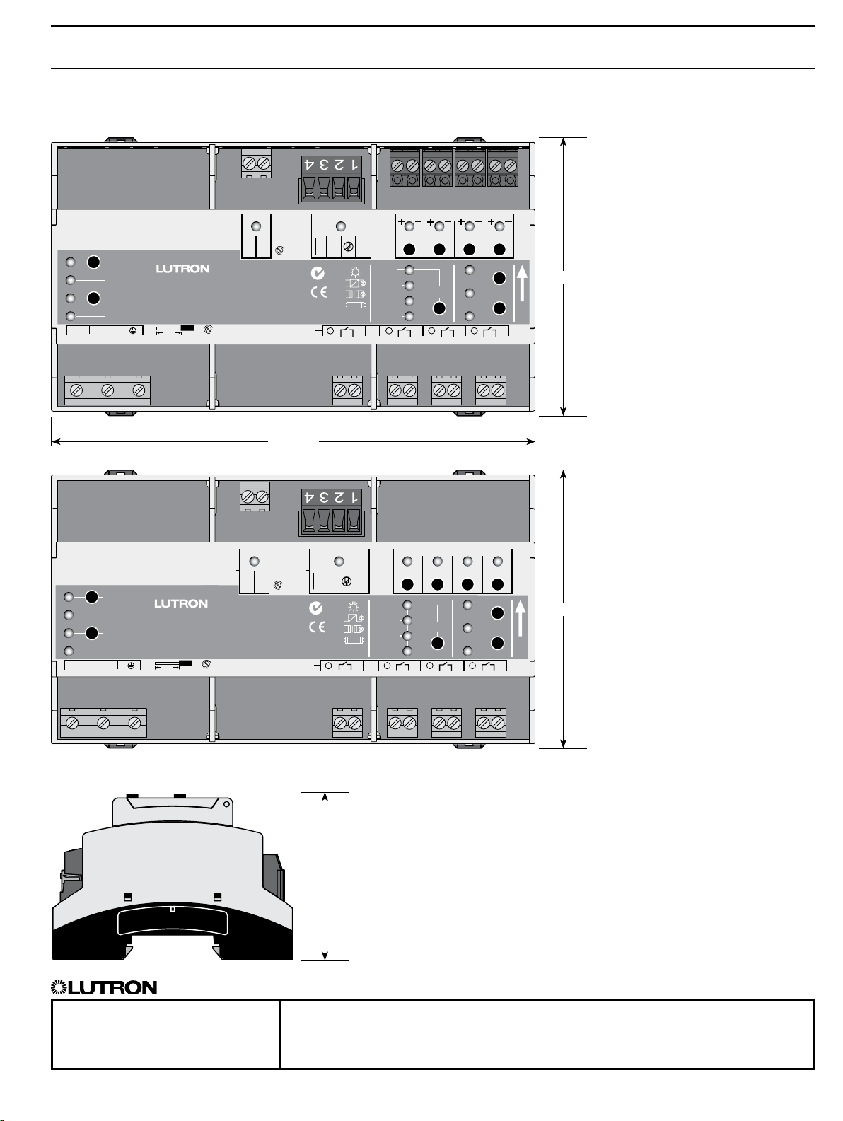
• Width = 9 modules (161.7 mm)
Programming and Compatibility Requirements
• LQSE-4T10-D and LQSE-4S10-D can be used only
with the HomeWorksQS system.
• HomeWorksQS software version 3.0 or higher
required.
Output Zone Ratings
• Each zone is rated at 10 AX for switching. Rated for
resistive, capacitive, or inductive lighting loads as
defined by IEC/EN 60669-2-1.
• Switched outputs utilize latching relays to maintain
relay state if control power is lost.
• 0 –10 V rated for 50 mA maximum output, source or
sink per zone.
SPECIFICATION SUBMITTAL Page
Job Name: Model Numbers:
HomeWorks QS Wallstations
• HomeWorks QS wallstations can be configured to
control Power Modules with the HomeWorks QS
programming utility.
• LED indicator displays the status of programmed
lights.
QS Link Limits
• A QS link in a HomeWorks QS system can have up
to 512 zones (outputs) and 100devices.
• Each Power Module counts as one device toward
the 100 device limit.
Manual Mode Operation
• Zone buttons:
– selects zone to control
• Raise/Lower buttons:
– turns loads on and off
– dim loads up and down (LQSE-4T10-D only)
Note: Program, Input, and Option buttons are not
used in LQSE models.
Contact Closure Input (CCI)
• The CCI behaves as a Manual Override Closure
Input.
• If the CCI is open, the Power Module unit will enter
Manual Override Mode, which will turn on all loads
and disable control from other devices.
• When the CCI is closed or jumpered (factory default),
Power Module unit zones will return to the settings or
levels they were at prior to entering Manual Override
Mode.
!
WARNING — Entrapment hazard — May result
in serious injury or death. These controls should only
be used to control equipment which is visible from
every control location.
!
WARNING – Fire hazard – May result in serious
injury or death. Only use these controls to operate
approved load and equipment types.
IMPORTANT NOTE:
Examples of such equipment which must not be
operated by these controls include (but are not
limited to) motorized gates, garage doors, industrial
doors, microwave ovens, heating pads, fireplaces,
space heaters, etc. It is the installer’s responsibility to
ensure that the equipment being controlled is visible
from every control location and that only suitable
equipment is connected to these controls.Failure to
do so could result in serious injury or death.
Job Number:
Page 3

Switching / 0 – 10 V Power Module Switching / 0 – 10 V Fixture Controller
3
LQSE-4
369610c 3 01.09.24
Overview of Wiring Terminals
LQSE- 4T10-D
Contact
Closure
Input
IEC PELV
QS Link
0 –10 V Channels
Zone
Zone
1
2
Zone
3
Zone
4
Input
Hi Temp
Program
Power
L
N
Mains Wiring
LQSE- 4S10- D
CCI
CCI
0-10 V Power Module
LQSE-4T10-D
230 V~ 50/60 Hz 50 mA
www.lutron.com +44.(0)20.7680.4481
8 mm
1,2 N•m
Outputs 230 V~ 10 AX each
Mains Only
Contact
Closure
Input
QS
0,5 N•m
All Others
COM
IEC PELV
Zone 1Zone 2Zone 3Zone 4
Zones
0-10 V50 mA
MUX
MUX
µ
COM
Z096
1 2
Zone
1
Def
Opt1
Opt2
Opt3
Zone
Option
3
Zone
2
3
Load power and switched outputs
QS Link
H
M
L
4
Zone
Up
4
Input
Hi Temp
Program
Power
L
N
Mains Wiring
CCI
CCI
Switching Power Module
LQSE-4S10-D
230 V~ 50/60 Hz 50 mA
www.lutron.com +44.(0)20.7680.4481
8 mm
1,2 N•m
Outputs 230 V~ 10 AX each
Mains Only
COM
0,5 N•m
All Others
QS
µ
MUX
MUX
COM
Z096
1 2
Zone
1
Zone 1Zone 2Zone 3Zone 4
Def
Opt1
Opt2
Opt3
Zone
2
Option
3
Zone
3
H
M
L
4
Zone
Up
4
Load power and switched outputs
SPECIFICATION SUBMITTAL Page
Job Name: Model Numbers:
Job Number:
Page 4
Switching / 0 – 10 V Power Module Switching / 0 – 10 V Fixture Controller
500-13431 Rev. B
N1771
Z096
4
LQSE-4
369610c 4 01.09.24
Mechanical Dimensions
LQSE- 4T10-D
Input
Hi Temp
Program
Power
L
N
LQSE- 4S10- D
Input
Hi Temp
Program
Power
L
N
CCI
COM
CCI
0-10 V Power Module
LQSE-4T10-D
230 V~ 50/60 Hz 50 mA
www.lutron.com +44.(0)20.7680.4481
8 mm
1,2 N•m
Outputs 230 V~ 10 AX each
Mains Only
161.7 mm
CCI
COM
CCI
Switching Power Module
LQSE-4S10-D
230 V~ 50/60 Hz 50 mA
www.lutron.com +44.(0)20.7680.4481
8 mm
1,2 N•m
Outputs 230 V~ 10 AX each
Mains Only
0,5 N•m
All Others
0,5 N•m
All Others
QS
µ
QS
µ
MUX
MUX
Z096
1 2
MUX
MUX
COM
Z096
1 2
Zone 1Zone 2Zone 3Zone 4
Zones
0-10 V50 mA
COM
Def
Opt1
Opt2
Option
Opt3
3
Zone 1Zone 2Zone 3Zone 4
Def
Opt1
Opt2
Option
Opt3
3
H
89.7 mm
M
Up
L
4
H
89.7 mm
M
Up
L
4
60.6 mm
SPECIFICATION SUBMITTAL Page
Job Name: Model Numbers:
Job Number:
Page 5
Switching / 0 – 10 V Power Module Switching / 0 – 10 V Fixture Controller
5
LQSE-4
369610c 5 01.09.24
Mains Voltage Wiring
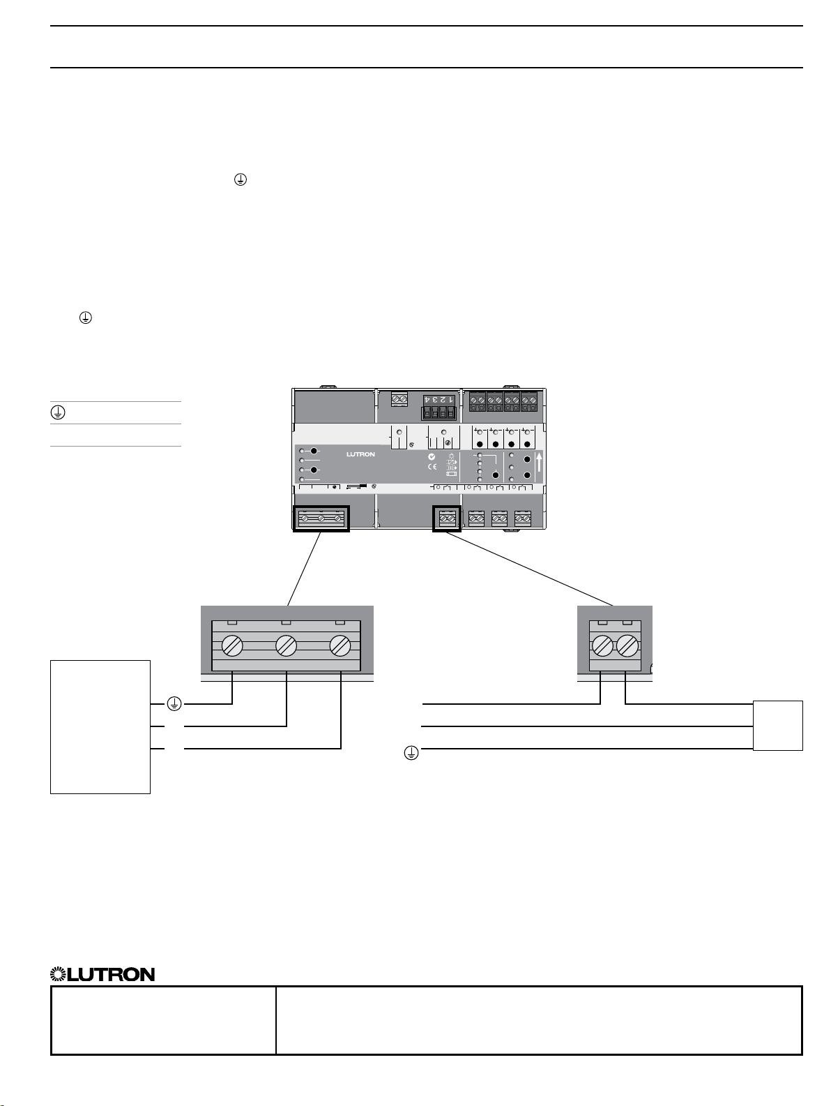
Wiring from Distribution to Power Module unit
• Turn off all circuit breakers or isolators feeding the
Power Module unit at distribution panel.
• Run live, neutral, and earth (
50/60 Hz feed to the Power Module unit.
Mains Wiring and IEC PELV Separation
• Follow appropriate local and national codes to avoid
violating required separation guidelines.
Behavior During Power Failure
• Relays do not change state when power is lost to the
L/N/ terminals. Follow local and national codes for
emergency lighting requirements.
Key
Earth/Ground
Neutral
N
Mains/Live
L
) wires from a 230 V~
CCI
Input
Hi Temp
0-10 V Power Module
LQSE-4T10-D
Program
230 V~ 50/60 Hz 50 mA
Power
www.lutron.com +44.(0)20.7680.4481
L
N
1,2 N•m
Mains Only
8 mm
0,5 N•m
All Others
COM
CCI
Outputs 230 V~ 10 AX each
QS
MUX
Z096
µ
1 2
MUX
COM
Zone 1Zone 2Zone 3Zone 4
Zones
0-10 V50 mA
Def
Opt1
Option
Opt2
Opt3
3
H
M
Up
L
4
Distribution
Panel
N
L
SPECIFICATION SUBMITTAL Page
Job Name: Model Numbers:
Job Number:
Zone 1 example
Switched Outputs: 230 V~ Switched Live
L
N
Load
Page 6
Switching / 0 – 10 V Power Module Switching / 0 – 10 V Fixture Controller
6
LQSE-4
369610c 6 01.09.24
Wiring: 0 – 10 V
MUX
MUX
Z096
1 2
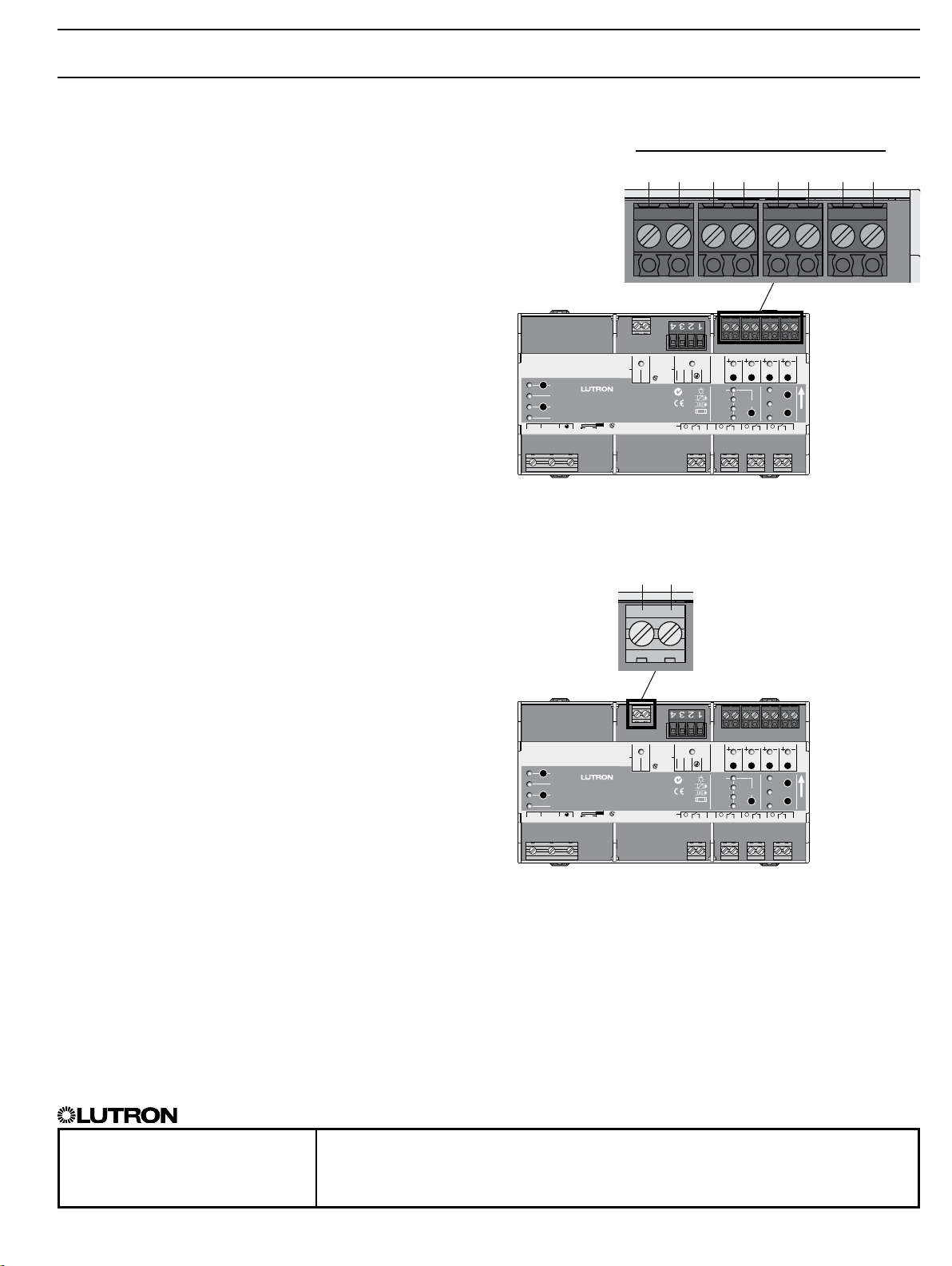
0 –10 V Wiring
Zone 2
+ –
Zone 1Zone 2Zone 3Zone 4
Zones
0-10 V50 mA
COM
Def
Opt1
Option
Opt2
Opt3
3
Zone 3
+ –
H
M
L
4
Zone 4
+ –
Up
0 –10 V Wiring (LQSE-4T10-D only)
• 0 –10V zones 1– 4 are double-insulated from all
other inputs and outputs.
• 0 –10V zones 1– 4 are not insulated from each other.
They share the same common terminal (negative “–”
terminal).
• Connect only SELV/IEC PELV circuits, or connect
only non-SELV/IEC PELV circuits to 0 –10V zones
1– 4. Do not mix SELV/IEC PELV circuits and
non-SELV/IEC PELV circuits.
• Follow all national and local electrical codes for
separation requirements.
Zone 1
+ –
CCI
QS
0,5 N•m
All Others
COM
1,2 N•m
Mains Only
CCI
µ
Outputs 230 V~ 10 AX each
Input
Hi Temp
0-10 V Power Module
LQSE-4T10-D
Program
230 V~ 50/60 Hz 50 mA
Power
N
www.lutron.com +44.(0)20.7680.4481
8 mm
L
Wiring: Manual Override Contact
Closure Input
IEC PELV Manual Override Contact Closure Input
• Contact Closure Input (CCI) wiring is IEC PELV.
Follow all applicable national and local codes for
proper circuit separation and protection.
• When in Manual Override mode, all ballasts and
modules will be at their programmed Manual
Override light level (default is 100%). All other
controls are locked out.
• Manual Override contact closure input is normally
closed (NC). The Power Module unit is shipped with
a jumper pre-installed.
Note: The Power Module unit will default to Manual
Override Mode if the CCI is left open. If no Manual
Override contact input is required, please leave the
wire jumper in the CCI terminals.
CCI Common
CCI
QS
0,5 N•m
All Others
COM
1,2 N•m
Mains Only
CCI
µ
Outputs 230 V~ 10 AX each
Input
Hi Temp
0-10 V Power Module
LQSE-4T10-D
Program
230 V~ 50/60 Hz 50 mA
Power
N
www.lutron.com +44.(0)20.7680.4481
8 mm
L
MUX
MUX
Z096
1 2
Zone 1Zone 2Zone 3Zone 4
Zones
0-10 V50 mA
COM
Def
Opt1
Opt2
Opt3
Option
3
H
M
Up
L
4
SPECIFICATION SUBMITTAL Page
Job Name: Model Numbers:
Job Number:
Page 7

Switching / 0 – 10 V Power Module Switching / 0 – 10 V Fixture Controller
7
LQSE-4
369610c 7 01.09.24
Wiring: QS Link
1,2 N•m
Mains Only
CCI
4: MUX
0,5 N•m
All Others
COM
CCI
Outputs 230 V~ 10 AX each
3: MUX
2: (no connection)
QS
µ
MUX
MUX
Z096
1 2
Zone 1Zone 2Zone 3Zone 4
Zones
0-10 V50 mA
COM
Def
Opt1
Opt2
Opt3
1: COM
Option
3
H
M
Up
L
4
IEC PELV QS Link Wiring
• Link communicates using IEC PELV wiring.
• Follow all applicable national and local codes for
proper circuit separation and protection.
• Wiring may be daisy-chained or T-tapped.
• Total length of QS link must not exceed 600 m.
• Wire Gauge:
– Power (terminals 1 and 2): 1 pair 1.0mm
2
– Data (terminals 3 and 4): 1 pair 0.5mm2 to
1.0mm2, twisted and shielded.
– Can use Lutron cable GRX-CBL-346S-500
• Do NOT connect terminal 2.
Input
Hi Temp
0-10 V Power Module
LQSE-4T10-D
Program
230 V~ 50/60 Hz 50 mA
Power
N
www.lutron.com +44.(0)20.7680.4481
8 mm
L
The Lutron logo, Lutron, HomeWorks, and GRAFIK Eye are trademarks or registered trademarks of Lutron Electronics Co., Inc. in the US and/or
other countries.
All other product names, logos, and brands are property of their respective owners.
SPECIFICATION SUBMITTAL Page
Job Name: Model Numbers:
Job Number:
 Loading...