

Page 1
DE
EN
FR
IT
ES
CDA3000
Betriebsanleitung
Operation Manual
Manuel d’utilisation
Istruzioni di esercizio
D
Umrichtersystem
750 W - 132 kW
Inverter Drive System
Système variateur
Sistema invertitore
Page 2
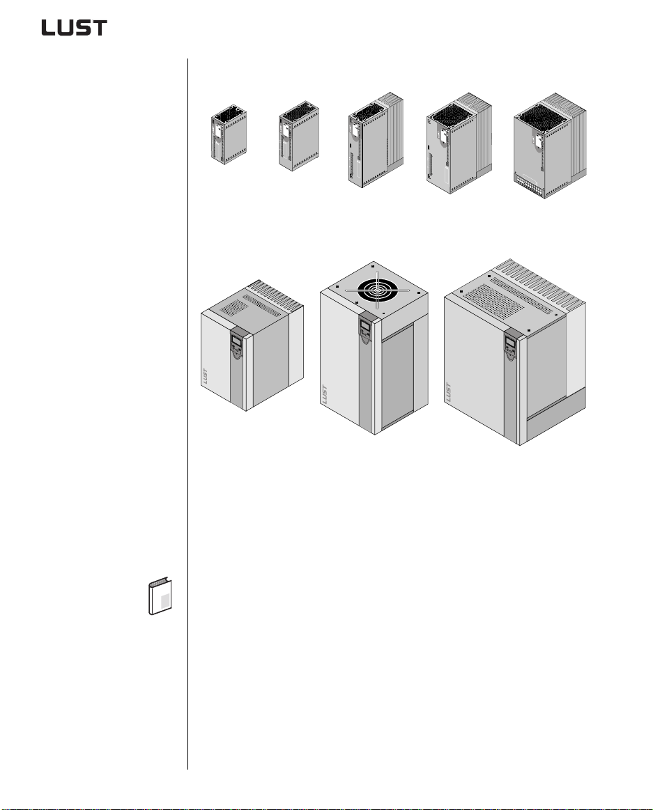
Sizes (BG)
BG1
0,75kW
1
a
A
N
T
H
R
I
EB
D
1
S
-
T
3
E
5
C
6
H
H
N
3
IK
3
2
L
a
h
n
H
a
u
3
T
y
p
X
:
4
N
e
t
z
:
A
u
s
g
.
:
S
N
.
:
X
1
0
0
0
.
0
0
U
0
.
0
0
0
0
0
0
0
V
0
W
X
2
!
R
B
+
R
B
ATTENTION
L
temps de decharge
-
du condensteur
>3 min. observer le
mode dèmploi!
L
1
WARNING
capacitor disscharge
L
2
time >3 minutes.
Pay attention to the
operation manual!
L
3
ACHTUNG
Kondensatorent-
ladezeit >3 Min.
Betriebsanleitung
X
beachten!
3
CDA32.004
BG2
0,75...2,2kW
AN
TR
H
I
EB
D
1
S
-
T
3
EC
5
6
H
H
N
3
IK
3
2
L
a
h
n
H
a
u
3
T
y
p
X
:
4
N
e
tz
:
A
u
s
g
.:
S
N
.
:
X
1
0
0
0
.
0
0
U
0
.
0
0
0
0
0
0
0
V
0
W
X
2
!
R
B
+
R
B
ATTENTION
L
temps de decharge
-
du condensteur
>3 min. observer le
mode dèmploi!
L
1
WARNING
capacitor disscharge
L
2
time >3 minutes.
Pay attention to the
operation manual!
L
3
ACHTUNG
Kondensatorent-
ladezeit >3 Min.
Betriebsanleitung
X
beachten!
3
CDA32.006
CDA32.008
CDA34.003
CDA34.005
CDA34.006
BG3
3,0...4,0kW
A
N
T
H
RI
E
BS
D
1
-
T
3
E
5
CH
6
H
N
3
IK
3
2
L
a
h
n
H
a
u
3
T
y
p
X
:
4
N
e
t
z
:
A
u
s
g
.:
S
N
.
:
0
0
0
.
0
0
0
.
0
0
0
0
0
0
0
0
X
2
X
1
U
V
W
X
3
R
B
+
!
R
B
L
-
ATTENTION
temps de decharge
du condensteur
>3 min. observer le
mode dèmploi!
L
1
L
2
WARNING
capacitor disscharge
L
3
time >3 minutes.
Pay attention to the
operation manual!
ACHTUNG
Kondensatorent-
ladezeit >3 Min.
Betriebsanleitung
beachten!
CDA34.008
CDA34.010
BG4
5,5...7,5kW
A
N
T
H
R
IE
B
D
1
S
-
TE
3
5
C
H
6
H
N
3
IK
3
2
L
a
h
n
H
a
u
3
T
y
p
X
:
4
N
e
tz
:
A
u
s
g
.:
S
N
.
:
0
0
0
.
0
0
0
.
0
0
0
0
0
0
0
0
X
2
X
1
U
V
W
R
B
+
R
B
X
3
L
-
!
L
1
L
2
L
ATTENTION
3
temps de decharge
du condensteur
>3 min. observer le
mode dèmploi!
WARNING
capacitor disscharge
time >3 minutes.
Pay attention to the
operation manual!
ACHTUNG
Kondensatorent-
ladezeit >3 Min.
Betriebsanleitung
beachten!
CDA34.014
CDA34.017
BG5
11...15kW
AN
T
H
RI
E
BS
D
1
-
T
3
E
5
C
HN
6
H
3
IK
3
2
L
a
h
n
H
a
u
3
T
y
p
X
:
4
N
e
t
z
:
A
u
s
g
.:
S
N
.
:
0
0
0
.
0
0
0
.
0
0
0
0
0
0
0
0
X
2
X
3
A
C
H
T
U
K
N
on
G
d
e
la
n
s
d
a
e
to
z
ei
r
B
W
e
t
e
n
A
>
tr
t
R
3
i
eb
N
M
b
c
IN
s
e
ap
in
a
G
a
n
.
c
a
l
h
c
e
t
it
t
it
e
im
o
u
n
r
n
!
d
e
g
>
i
s
P
3
s
a
c
y
m
h
A
ar
a
i
T
n
tte
T
o
L
g
u
E
p
e
te
n
N
e
1
t
s
te
ra
T
i
o
.
IO
m
n
t
ion
to
N
p
s
d
d
m
t
L
u
h
e
a
c
e
d
n
2
o
u
e
n
>
a
c
d
l
h
3
!
e
a
n
m
r
s
g
L
te
i
e
n
mo
.
u
3
o
r
d
b
e
s
d
e
rv
è
m
er
p
le
lo
i!
L
-
!
R
B
R
B
+
U
V
W
CDA34.024
CDA34.032
BG6
22...37kW
CDA34.045
CDA34.060
CDA34.072
45...55kW
CDA3000 Operation Manual
ID no.: 0840.00 B.4-00 • 05/2003
D
Valid from software version V3.2
BG7
CDA34.090
CDA34.110
BG8
75...132kW
CDA34.143
CDA34.170
CDA34.250
We reserve the right to make technical changes.
Page 3
Dear user,
Step Action Comment
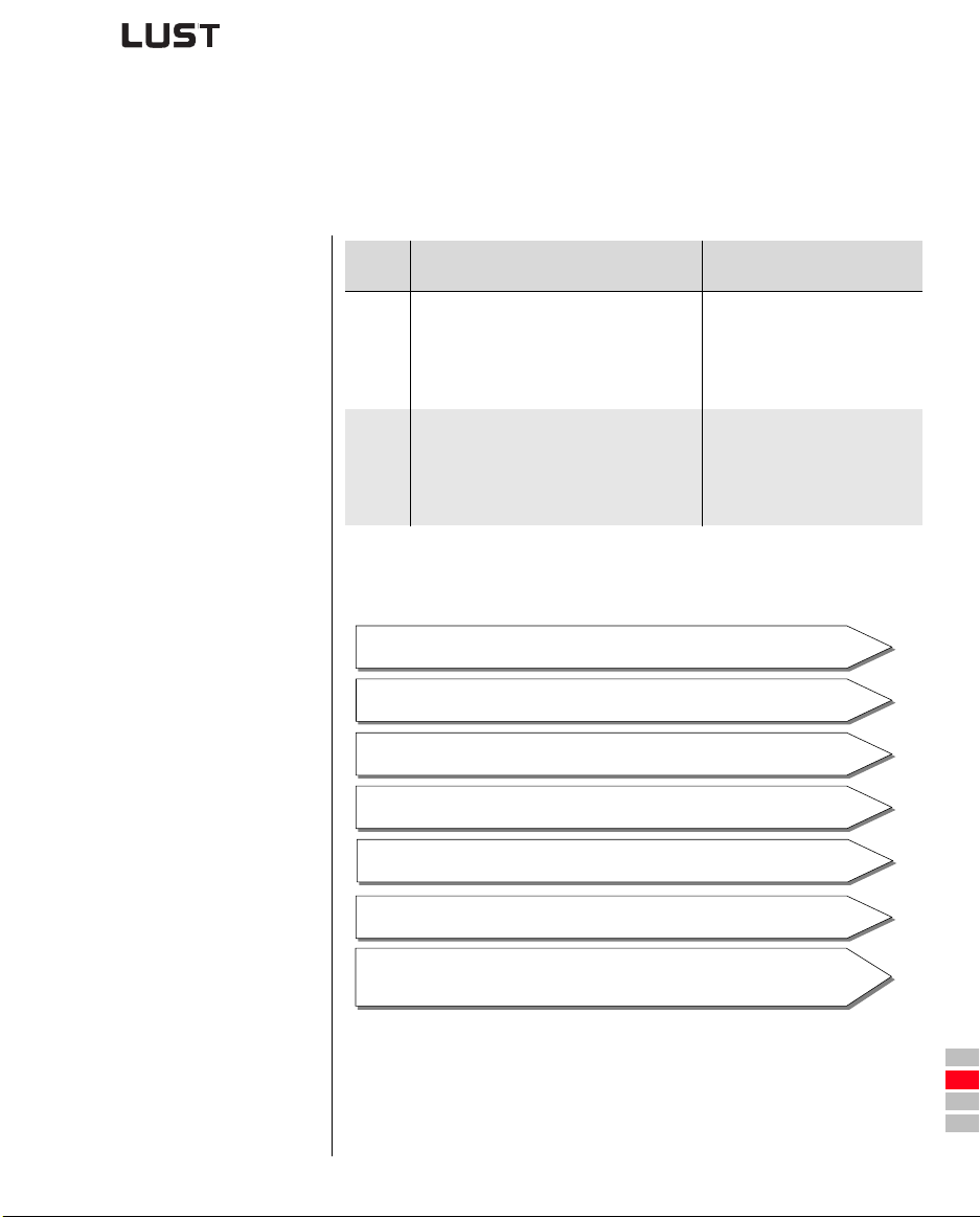
This Operation Manual will enable you
to install and commission the
1
CDA3000 drive system very quickly
Guide to quick-starting
and easily.
Simply follow the step-by-step tables
in sections 2/3/4.
2
Experience “Plug 'n Play” with the
And away you go!
CDA3000.
Signposts
CDA3000 Operation Manual
Contents
1 Safety
2 Mechanical installation
3 Installation
4 Commissioning
5 Diagnose/Fault rectification
Appendix:
Technical data, Ambient conditions,
Project planning notes, UL approbation
1
2
3
4
5
A
DE
EN
FR
IT
Page 4
Overview
Documentation
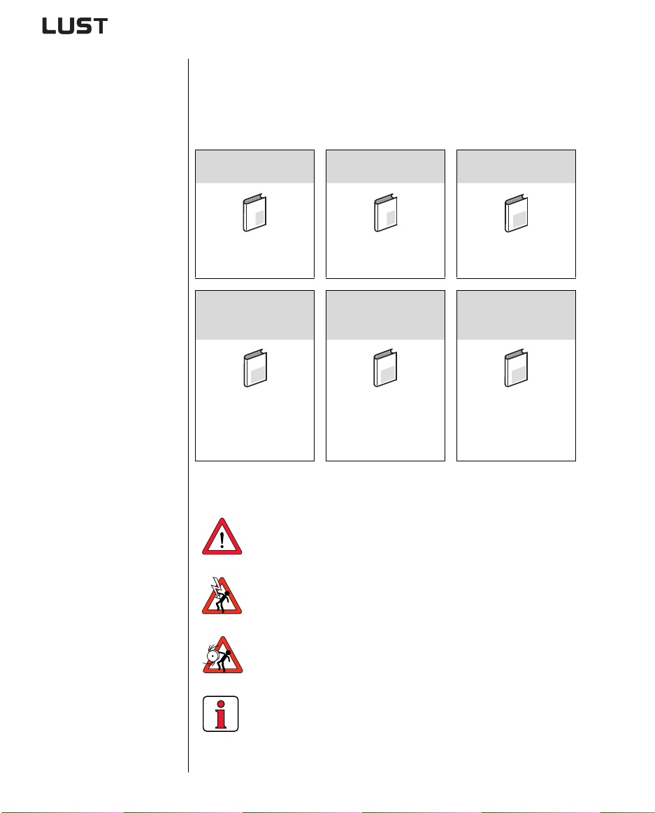
If you want more information on the drive solutions presented here and on
the full scope of software features of the drive system, please refer to
the CDA3000 Application Manual. You can order the following
documents from us, or download them free of charge from our website at
D
Lust
User Manual
EYPAD
K
E
Operation via
EYPAD KP200
K
CAN
Communication Module
open
Manual
G2
Project planning,
installation and
commissioning of the
CDA3000 on the field bus
Application Manual
CDA3000
F1
Adaptation of the drive
system to the application
PROFIBUS-DP
Communication Module
Manual
G3
Project planning,
installation and
commissioning of the
CDA3000 on the field bus
www.lust-tec.de:
CDA3000 Operation
Manual
Quick and easy initial
commissioning
CAN
Communication Module
Manual
G1
Project planning,
installation and
commissioning of the
CDA3000 on the field bus
Pictograms
CDA3000 Operation Manual
➢ Attention! Misoperation may result in damage to the
drive or malfunctions.
➢ Danger from electrical tension! Improper behaviour
may endanger human life.
➢ Danger from rotating parts! The drive may start
running automatically.
➢ Note: Useful informat io n
Page 5
1Safety
1
1.1 Measures for
your safety
CDA3000 Operation Manual
The CDA3000 inverter drives are quick and safe to handle. For your own
safety and for the safe functioning of your device, please be sure to
observe the following points:
Read the Operation Manual first!
• Follow the safety instructions!
Electric drives are dangerous:
• Electrical voltages > 230 V/460 V:
Dangerously high voltages may still be present
10 minutes after the power is cut. You should therefore
always check that no power is being applied!
• Rotating parts
• Hot surfaces
Your qualification:
• In order to prevent persona l injur y and damage to
property, only personnel wit h elect rical engineering
qualifications may work on the device.
• The qualified personnel must familiarize themselves with
the Operation Manual (refer to IEC36 4, DIN VDE0100).
• Knowledge of national accident prevention regulations
(e.g. VBG4 in Germany)
During installation observe the following instructions:
• Always comply with the connec tion conditions and
technical specifications.
• Comply with the standards for electrical installations,
such as regarding wire cross-section, grounding lead
and ground connections.
• Do not touch electronic components and contacts
(electrostatic discharge may destroy components).
1-1
2
3
4
5
A
DE
EN
FR
IT
ES
FR
Page 6
1 Safety
1.2 Intended use Inverter drives are components that are intended for installation in
electrical systems or machines. The drive may not be commissioned
(i.e. it may not be put to its intended use) until it has been established that
the machine as a unit complies with the provisions of the Machinery
Directive (98/37/EC). EN 60204 (Safety of machines) is to be observed.
The CDA3000 conforms to the Low Voltage Directive
DIN EN 50178.
EMC Application of the installation instructions ensures
conformance to product standard EN 61800-3. It covers:
• Public low voltage system:
Residential areas up to 10 metres motor cable length
• Industrial low voltage system:
Industrial areas up to 25 metres mot or cable length
Warning: This is a product with restricted availability in accordance with
IEC 61800-3. The Inverter Drive System may cause radio frequency
interference in residential environments. In such cases operators may
need to implement appropriate coun termeasures.
If the frequency inverter is used for special applications (e.g. in areas
subject to explosion hazard), the required standards and regulations
(e.g. EN 50014, “General provisions” and EN 50018 “Flameproof
housing”) must always be observed.
Repairs may only be carried out by authorized repair workshops.
Unauthorized opening and incorrect int ervention could lead to physical
injury or material damage. The warranty provided by LUST would thereby
be rendered void.
1.3 Responsibility Electronic devices are fundam entally not fail-safe. The compa ny setting
up and/or operating the machine o r plant is itself responsible for ensuring
that the drive is rendered safe if the device fails.
EN 60204-1/DIN VDE 0113 “Safety of machines”, in the section on
“Electrical equipment of machines”, stipulates safety requirements for
electrical controls. They are intended to protect personnel and machinery,
and to maintain the function capability of the machine or plant concerned,
and must be observed.
The function of an emergency off system does not necessarily have to cut
the power supply to the drive. To protect against danger, it may be more
beneficial to maintain individual drives in op eration or to initiate specific
safety sequences. Ex ecution of the emer gency off measure is ass essed
by means of a risk analysis of the machine or plant, including the
electrical equipment to DIN EN 1050, and is de termin ed with selec tion of
the circuit category in accordance with DIN EN 954-1 “Safety of machines
- Safety-related parts of controls”.
CDA3000 Operation Manual
1-2
Page 7
2 Mechanical installation
2.1 Notes for operation .................................................2-1
2.2 Mounting variants ...................................................2-1
2.3 Wall mounting .........................................................2-2
2.4 Cold plate ................................................................2-4
2.5 Push-through heat sink (Dx.x) ...............................2-7
1
2
3
2.1 Notes for operation
2.2 Mounting variants
CDA3000 Operation Manual
Please ensure that ...
• no damp enters the device
• no aggressive or conductive substances are in the immediate vicinity
• no drill chippings, screws or foreign bodies drop int o the device
• the vent openings are not co vered over.
The device may otherwise be damaged.
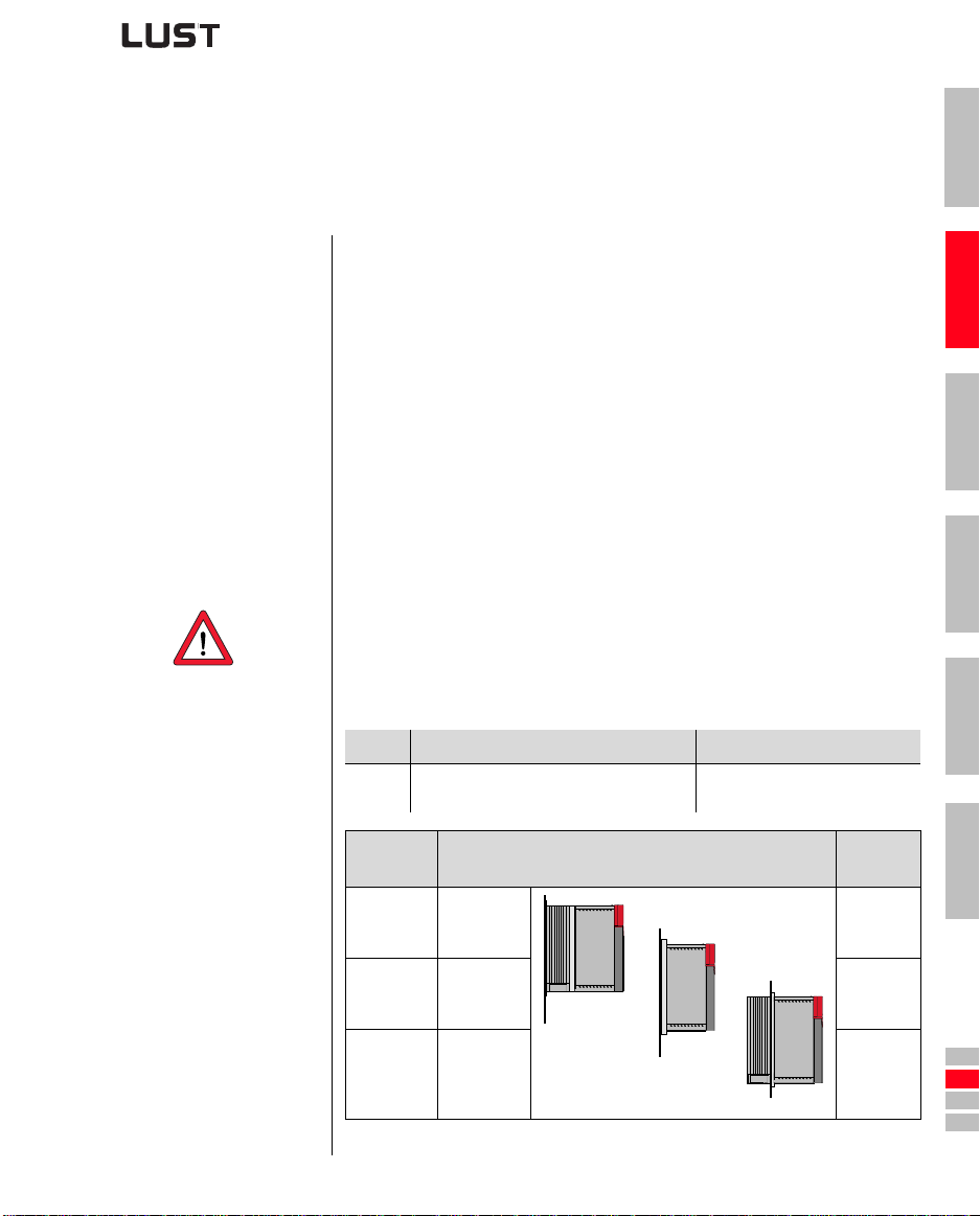
Step Action Comment
Refer to the name plate to find out the
1
mounting variant of your inverter module.
Name plate Mounting and cooling variant
CDA3...,Wx.x
CDA3...,Cx.x Cold plate Page 2-4
CDA3...,Dx.x
Table 2.1 Mounting and cooling variants
Wall
mounting
Wx.x
Push-through
heat sink
2-1
The mounting variants differ in
their mode of cooling.
Continued
on
Page 2-2
Cx.x
Page 2-7
Dx.x
4
5
A
DE
EN
FR
IT
ES
FR
Page 8
2 Mechanical installation
;
;
;
;
y
y
y
y
2.3 Wall mounting
Step Action Comment
Mark out the position of the tapped holes
on the backing plate.
1
Cut a tap for each fixing screw in the
backing plate.
Dimensional drawings/hole
spacing see Table 2.2.
The tapping area will provide
you with good, full-area contact.
Pay attention to the mounting
Mount the inverter module vertically on
2
the backing plate.
clearances!
The contact surface must be
metallically bright.
Mount the other components, such as the
mains filter, line choke etc., on the
3
backing plate.
Continue with the electrical installation in
4
section 3.
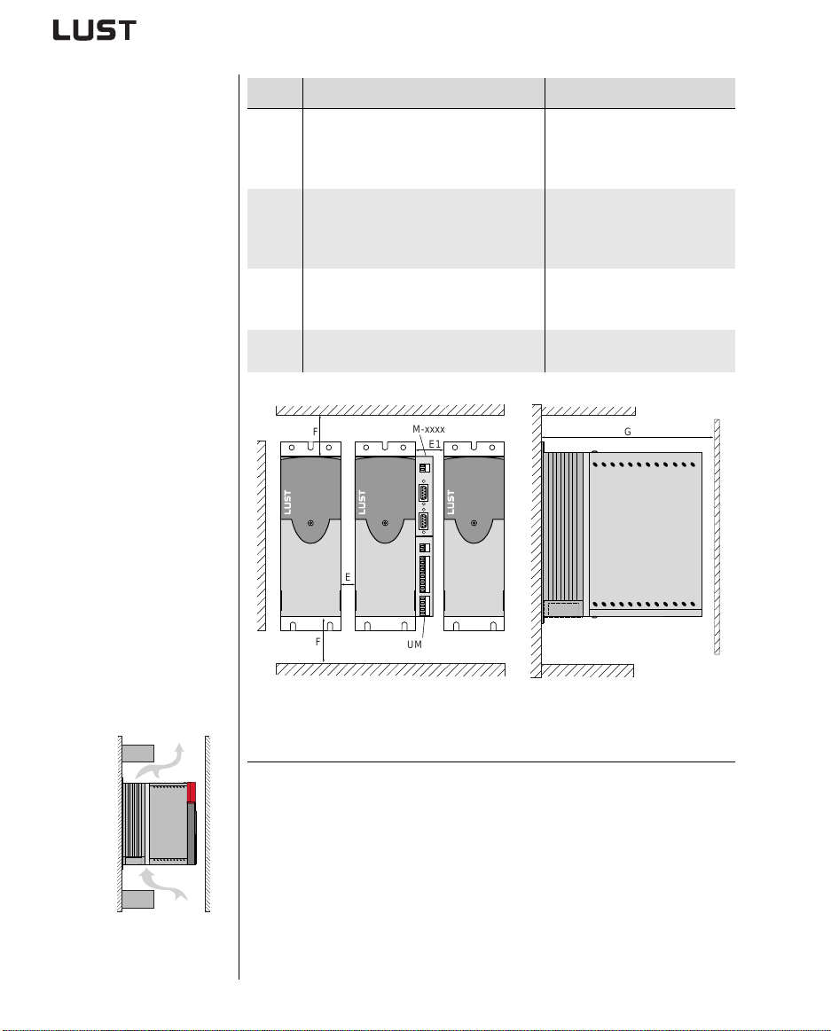
F
E
CM-xxxx
E1
Mains filter max. 20 cm below
the inverter module
G
CDA3000 Operation Manual
F
UM-xxxx
Figure 2.1 Mounting clearances (see Table 2.2)
Note the following points:
• Air must be able to flow unhindered through the device.
• For mounting in switch cabinets with convection (= heat loss is
discharged to the outside via the cabinet walls) an internal air
circulation fan must always be fitted.
• The backing plate must be well grounded.
• The best result for effective EMC installati on is attained with a
chromated or galvanized backing plat e. If backing plates are
varnished, the coating must be removed in the area of the contact
surface!
2-2
Page 9
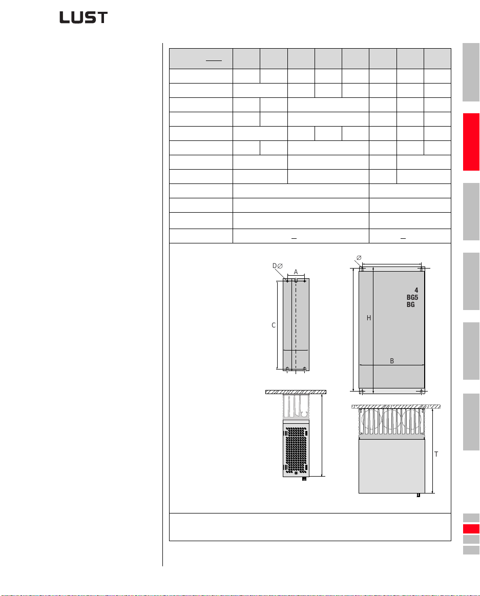
2 Mechanical installation
CDA3...,Wx.x
Weight [kg] 2.4 3.5 4.4 6.5 7.2 20 31 60
W (width) 70 70 120 170 250 300 412
H (height) 245 270 330 375 600 510
D (depth) 195 220 218 325 305 380
A 40 40 80 130 215 265 340
C 235 260 320 360 555 485
D∅ ∅ 4.8 ∅ 4.8 ∅ 6 ∅ 9
Screws 4 x M4 4 x M4 4 x M5 4 x M8
E 0 50
E1 (with module) 45 –
F 100
G > 300 > 400
BG12)BG2
2)
BG3 BG4 BG5 BG6 BG7 BG8
100
1)
1
2
3
CDA3000 Operation Manual
D
A
BG1
BG2
H
C
B
1) Additionally allow enough space at the bottom for the bending radii of the connecting cables.
2) Corresponding to cold plate version with accessory heat sink HS3X.xxx
Table 2.2 Dimensional drawings: Wall mounting (dimensions in mm)
D
C
T
A
BG3
BG4
BG5
BG6
H
BG7
BG8
B
2-3
4
5
A
T
DE
EN
FR
IT
ES
FR
Page 10
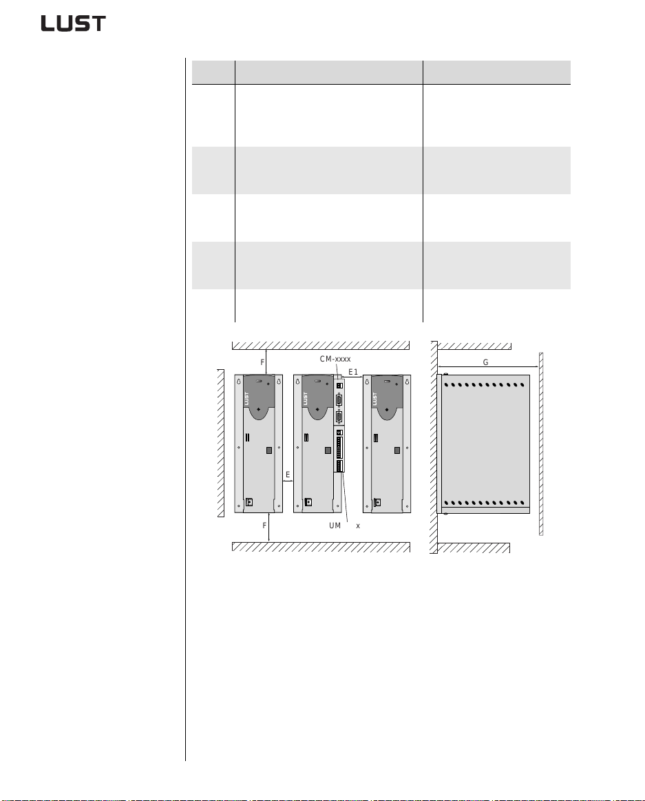
2 Mechanical installation
2.4 Cold plate
Step Action Comment
Mark out the positions of the tapped
holes on the backing plate or the cooler.
1
Cut a tap for each fixing screw in the
backing plate.
Clean the contact surface and coat it
thinly and evenly with heat transfer
2
compound.
Mount the inverter module vertically on
the backing plate or cooler. Tighten all
3
screws to the same tightness.
Mount the other components, such as the
mains filter, line choke etc., on the
4
backing plate.
Continue with the electrical installation in
5
section 3.
F
CM-xxxx
E1
Dimensional drawings/hole
spacing see Table 2.3.
The tapping area will provide
you with good, full-area contact.
The contact surface must be
metallically bright.
Pay attention to the mounting
clearances! Size of cooling
surface see Table 2.4.
Mains filter max. 20 cm below
the inverter module
G
CDA3000 Operation Manual
E
F
Figure 2.2 Mounting clearances (see Table 2.3)
UM-xxxx
2-4
Page 11
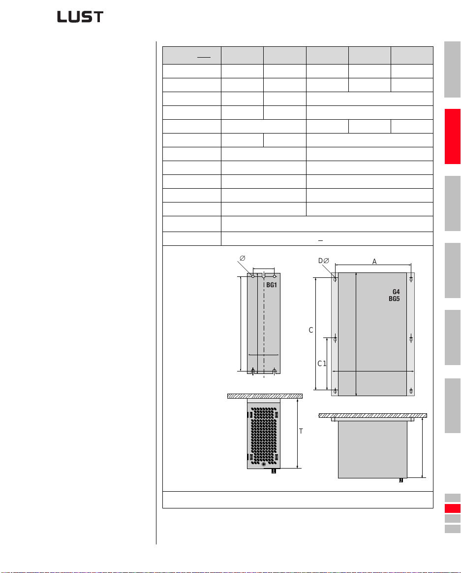
2 Mechanical installation
CDA3...,Cx.x BG1 BG2 BG3 BG4 BG5
Weight [kg] 1.6 2.3 3.2 5.2 6.4
W (width) 70 70 100 150 200
H (height) 215 240 300
D (depth) 120 145 150
A 50 85 135 185
C 205 230 200
C1 – 100
D∅ ∅ 4.8 ∅ 5.5
Screws 4 x M4 6 x M5
E 0 0
E1 (with module) 45 15
F
G > 300
100
1)
1
2
3
CDA3000 Operation Manual
D
A
BG1
BG2
H
C
B
1) Additionally allow enough space at the bottom for the bending radii of the connecting cables.
Table 2.3 Dimensional drawings: Cold plate (dimensions in mm)
D
C
C1
T
A
BG3
BG4
BG5
H
B
2-5
4
5
A
T
DE
EN
FR
IT
ES
FR
Page 12
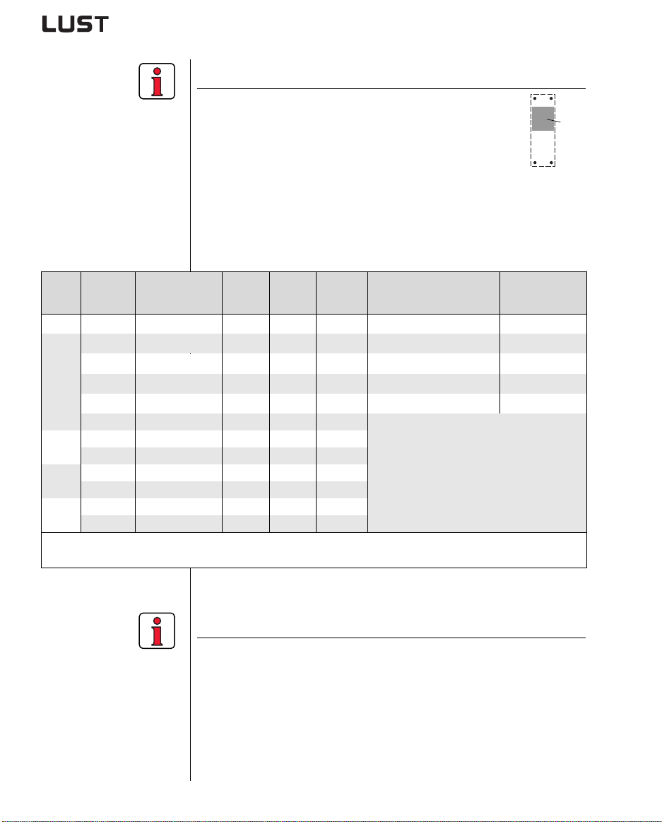
2 Mechanical installation
Note the following points:
• Cooling can be attained either by a sufficiently large
backing plate (see T able 2.4) or by an additional cooler.
The cooler must be mounted centrally behind the
hottest area (1) of the device.
• The temperature on the rear panel of th e inverter
module must not exceed 85.0 °C. At a temperature
> 85° C the device shuts down automatically. It can only be
restarted when it has cooled.
• Required evenness of contact surf ace = 0.05 mm, maximum
roughness of contact surface = roughness factor 6.3
.
(1)
Size Power Inverter module
PV at
4 kHz
PV at
8/16 kHz
R
thK
[K/W]
3)
Backing plate (unvarnished
steel min. cooling surface
BG1 0.75 kW CDA32.004,Cx.x 48 W 55 W 0.05 650x100mm = 0.065m²
1.1 kW CDA32.006,Cx.x 75 W 82 W 0.05 650x460mm = 0.3m²
1.5 kW CDA32.008,Cx.x 95 W 105 W 0.05 650x460mm = 0.3m²
BG2
0.75 kW CDA34.003,Cx.x 55 W 70 W 0.05 None
1.5 kW CDA34.005,Cx.x 80 W 112 W 0.05 650x460mm = 0.3m²
2.2 kW CDA34.006,Cx.x 106 W 148 W 0.05
3.0 kW CDA34.008,Cx.x 135 W 162 W 0.03
BG3
4.0 kW CDA34.010,Cx.x 172 W 207 W 0.03
5.5 kW CDA34.014,Cx.x 210 W 268 W 0.02
BG4
7.5 kW CDA34.017,Cx.x 255 W 325 W 0.02
BG5
1) At a power stage clock frequency of 4 kHz 2) At a power stage clock frequency of 8 kHz
3) Thermal resistance between active cooling surface and cooler
11 kW CDA34.024,Cx.x 315 W 400 W 0.015
15 kW CDA34.032,Cx.x 400 W 510 W 0.015
An additional cooler is required to supply
adequate cooling.
Project planning notessee appendix A.4
If you have any further questions please
consult your project engineer.
Table 2.4 Required cooling with cold plate
Note the following points:
• The backing plate must be grounded over a large area.
• For mounting in switch cabinets with convection (= heat loss is
discharged to the outside via the cabinet walls) an internal air
circulation fan must always be fitted.
• The best result for effective EMC installati on is attained with a
chromated or galvanized backing plat e. If backing plates are
varnished, the coating must be removed in the area of the contact
surface!
Ambient
temperature
45°C1), 40°C
45°C1), 40°C
45°C1), 40°C
45°C1), 40°C
45°C1), 40°C
2)
2)
2)
2)
2)
CDA3000 Operation Manual
2-6
Page 13
2 Mechanical installation
2.5 Push-through heat sink (Dx.x)
Step Action Comment
Mark out the positions of the tapped
holes and the breakthrough on the
backing plate.
1
Cut a tap for each fixing screw in the
backing plate.
Mount the inverter module vertically on
the backing plate. Tighten all screws to
2
the same tightness.
Mount the other components, such as the
mains filter, line choke etc., on the
3
backing plate.
Continue with the electrical installation in
4
section 3.
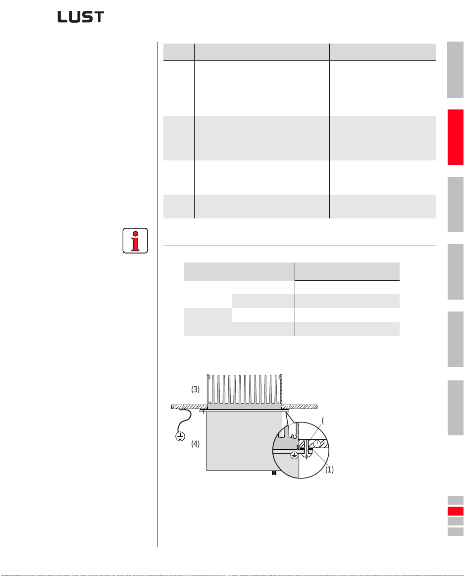
Note the following points:
• Distribution of power loss:
Power loss
Protection
Outside (3) 70% 75% 80%
Inside (4) 30% 25% 20%
Heat sink side (3) IP54 IP54 IP54
Machine side (4) IP20 IP20 IP20
Dimensional drawings/hole
spacing see Table 2.6.
The tapping area will provide
you with good, full-area contact.
Pay attention to the mounting
clearances! The mounting seal
must contact flush on the
surface.
Mains filter max. 20 cm below
the inverter module
BG3 BG4 BG5
1
2
3
4
CDA3000 Operation Manual
• The all-round mounting collar must be fitted with a seal. The seal
must fit flush on the surface an d must not be damaged:
(1) Seal
(3)
(4)
• The backing plate must be well grounded.
• The best result for effect ive EMC installation is attained with a
chromated or galvanized backing plate. If backing plates are
varnished, the coating must be rem oved in the area of the contact
surface!
(2) Tapped hole for EMC compatible contact
(3) Outside
(4) Inside
(2)
(1)
2-7
5
A
DE
EN
FR
IT
ES
FR
Page 14
2 Mechanical installation
F
F
CM-xxxx
E1
E
UM-xxxx
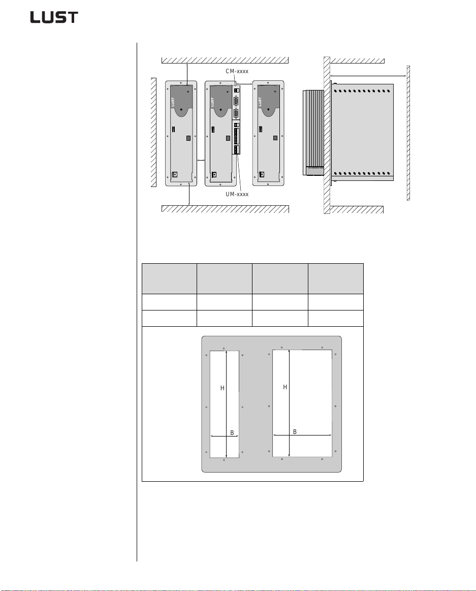
Figure 2.3 Mounting clearances (see Table 2.6)
Dimensions of
breakthrough
BG3 BG4 BG5
W (width) 75 125 175
H (height) 305 305 305
G
CDA3000 Operation Manual
H
B
H
B
Table 2.5 Breakthrough for push-through heat sink (dimensions in mm)
2-8
Page 15
2 Mechanical installation
For more information
on the ambient
conditions see
appendix A.3.
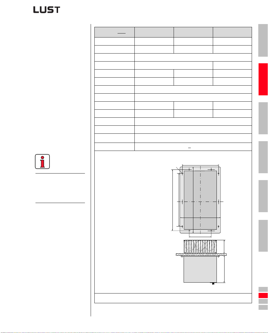
CDA3...,Dx.x BG3 BG4 BG5
Weight [kg] 4.6 6.7 7.4
W (width) 110 160 210
H (height) 340
D (depth) T1 138, T2 80 T1 138, T2 135
A 90 140 190
A1 – 80 100
C 320
C1 200
D∅ ∅ 4.8 ∅ 4.8 ∅ 4.8
Screws 8 x M4 10 x M4 10 x M4
E 10
E1 (with module) 20
F
G > 300
100
1)
1
2
3
CDA3000 Operation Manual
D∅
C1
C
1) Additionally allow enough space at the bottom for the bending radii of the connecting cables.
Table 2.6 Dimensional drawings: push-through heat sink (dimensions
in mm)
A
BG3
BG4
BG5
H
B
A1
T2
T1
2-9
4
5
A
DE
EN
FR
IT
ES
FR
Page 16

2 Mechanical installation
CDA3000 Operation Manual
2-10
Page 17
3 Installation
3.1 Overview ..................................................................3-2
3.2 Grounding lead connection .....................................3-3
3.3 Motor connection ....................................................3-4
3.4 Mains connection ....................................................3-6
3.5 DC network ..............................................................3-8
3.6 Braking resistor (RB) ..............................................3-9
3.7 Control connections ..............................................3-10
3.7.1 Choice of terminal assignment ...........................3-11
3.7.2 Specification of control terminals .......................3-12
3.7.3 Terminal assignment 1 ......................................3-13
3.7.4 Terminal assignment 2 ......................................3-14
3.7.5 Terminal assignment 3 ......................................3-15
3.7.6 Encoder .............................................................3-16
1
2
3
4
5
CDA3000 Operation Manual
Attention: Installation must only be carried out by qualified electricians
who have undergone instruction in the nec essary accident
prevention measures.
3-1
A
DE
EN
FR
IT
ES
FR
Page 18
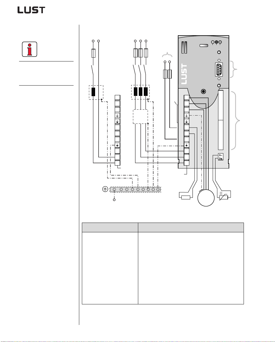
3 Installation
The terminal layout for all
sizes is presented in
Appendix A8.
3.1 Overview
(1)
L1
K1
(1)
(2)
CDA32.xxx
L2L3
FN
(7)
L+
L-
(8)
CDA34.xxx
X1
RB
(3)
H1 H2 H3
(6)
X4
20
M
3~
19
18
17
16
15
14
13
12
11
10
X3
9
8
7
6
5
4
3
2
1
(4)
X2
ϑ
(5)
U
V
W
L+
RB
L-
L3
L2
L1
L1 N
K1
X1
U
V
W
L+
RB
L-
N
L1
PE
CDA3000 Operation Manual
Figure 3.1 Overview of connectio ns
Key Explanation
(1) Line choke
(2) Mains filter
1)
1) 2)
(3) Braking resistor
1)
Reduces the voltage distortions in the system
Suppresses line-borne interference emission
Required for repeated braking
(4) Control conn. X2 Connection see section 3.7
(5) Motor PTC connection X3 For thermal monitoring of the motor, see section 3.3
(6) RS232 connection X4 For operation with KEYPADsee section 4.7/
RIVEMANAGERsee section 4.8
(7) Connection for
DC network
Operation with D
Permits power exchange between servocontrollers, see
section 3.5
(8) Software name plate Indicates the shipped software status
1) For supplementary components see CDA3000 Order Catalogue.
2) In inverter modules up to 7.5 kW (BG1 to BG4) the mains filter is built-in.
3-2
Page 19
3 Installation
;
;
;
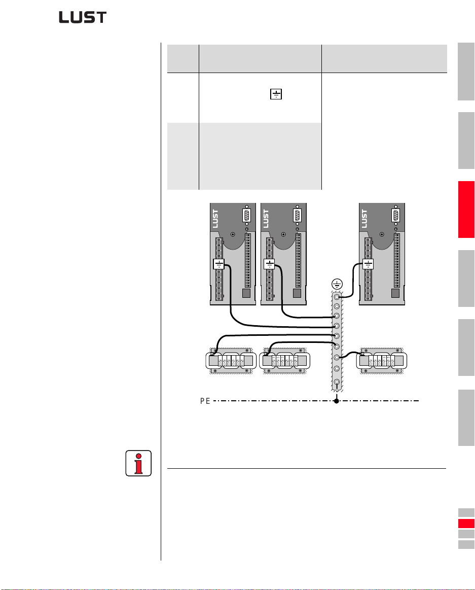
3.2 Grounding lead connection
Step Action
Ground every inverter module!
Connect terminal X1/ in star
1
configuration to the PE rail (main
ground) in the switch cabinet.
Also connect the grounding lead
connections of all other
components, such as the line choke,
2
filter, etc., in star configuration, to
the PE rail (main ground) in the
switch cabinet.
Note: PE mains connection to
DIN VDE 0100 part 540
Mains connection < 10 mm²:
Grounding lead cross-section min.
or use 2 wires with cross-
10 mm²
section of mains leads.
Mains connection > 10 mm²:
Use grounding lead (PE) cross section
according to cross-section of mains
leads.
1
2
3
4
CDA3000 Operation Manual
V2
U1
W1
U2
W2
V1
V2
U1
W1
U2
W2
V1
V2
U1
W1
U2
W2
V1
PE
Figure 3.2 Star configuration layout of the grounding lead
Note the following points:
• The grounding lead must be laid out in star configuration to conform
to the EMC standards.
• The backing plate must be well grounded.
• The motor cable, mains lead and control cable must be laid
separately from each other.
• Avoid loops, and lay cable over short distances.
• The operational leakage current is > 3.5 m A.
3-3
5
A
DE
EN
FR
IT
ES
FR
Page 20
3 Installation
The CDA3000 inverter
modules are protected
against shorting and
ground faults at the terminals when in operation. In the event of a
short-circuit or ground
fault in the motor cable,
the power stage is disabled and an error
message is delivered.
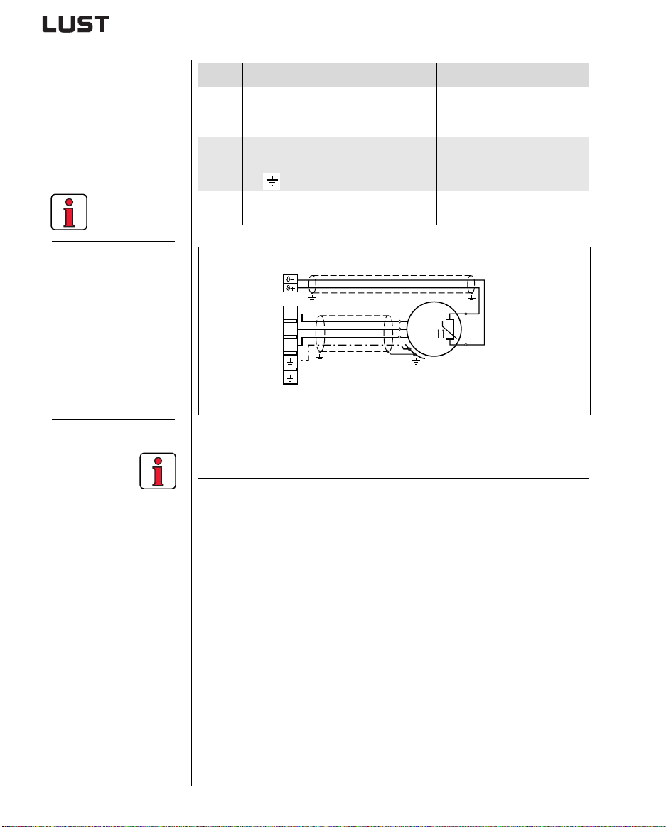
3.3 Motor connection
CDA3000 Operation Manual
Step Action Comment
Define the wire cross-section
dependent on the maximum current and
1
ambient temperature.
Wire the motor phases U, V, W by way of
a shielded cable and ground the motor to
2
.
X1/
Wire the temperature sensor PTC (if
3
fitted) with separately shielded wires.
X3
U
V
W
X1
Figure 3.3 Connection of motor
Wire cross-section to VDE0100,
part 523, see section 3.4
“Mains connection”.
Mount shield at both ends to
reduce interference emission.
Mount shield at both ends to
reduce interference emission.
M
1
ϑ
2
U
V
W
3~
Note the following points:
• Always use shielded cables to connect the motor.
• Shield contact on the inverter module:
− For inverter modules BG1 ... 5 (0.37 ... 15 kW) there is an
accessory shield (ST02, ST04 or ST05) permit tin g si m ple clip
mounting with all-round contact.
− For inverter modules BG6 ... 8 (22 ... 132 kW) we recommend
using a cable clamp rail with shield connection directly on the
cable gland in the switch cabinet.
• The motor at the inverter output may be shut off by means of a
contactor or motor circuit-breaker. The inverter module cannot be
damaged in the process. Circuit reference for „motor contactor“ see
appendix A.5.1.
• Multi-motor operation is possible; for project planning notes see
Appendix A.5.
3-4
Page 21
3 Installation
Attention: If the inverter is operated as a controller with encoder (FOR
motor control method), motor phases U,V and W must
never be reversed! If the motor phases are reversed the
inverter has no control over the motor. The motor may buck or
accelerate in an uncontrolled manner (“race”).
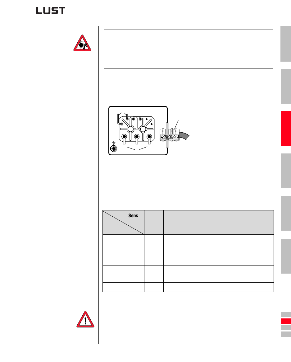
Ter m i n al box For proper EMC installation the motor terminal box must be HF-tight
(metal or metallized plastic). For cable introduction, p acking glands with
large-area shi e l d contact should be use d.
1
2
(1)
2
1
VW
U
VW
U
(3)
(4)
Figure 3.4 Motor terminal box
(2)
(1) Thermistor (PTC)
Packing gland with shield
(2)
contact
(3) Motor phases
(4) Grounding lead connection
Motor temperature monitoring For thermal monitoring of the motor coil, a thermistor (PTC) may be
connected to terminals X3/ ϑ- and ϑ+. The type used must be set during
commissioning in parameter 330-MOPTC (factory default setting is “off”).
Sensor
No PTC
Tech. data
Usable type -
Parameter
330-MOPTC =
Measurement
voltage U
MAX
Measuring range – 100 Ω to 15 kΩ –
Table 3.1 Motor temperature mo nitoring specification
used
OFF DIN KTY TSS
Standard
PTC
PTC to
DIN44082
– 12 V –
Linear
voltage evaluation
KTY84-130, (tolerance
band yellow)
TSS,
thermostatic
circuit-breaker
Klixon
3
4
5
A
CDA3000 Operation Manual
Attention: Contrary to DIN VDE 0660-303 (short circuit dedection
<20Ω) the CDA3000 will note a short circuit at < 5 Ω.
3-5
DE
EN
FR
IT
ES
FR
Page 22
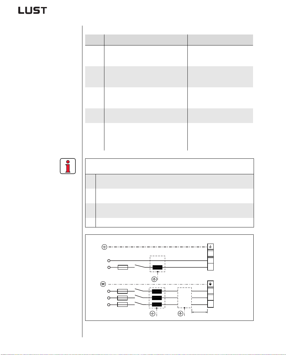
3.4 Mains connection
3 Installation
Step Action Comment
Define the wire cross-section
dependent on maximum current and
1
ambient temperature.
Wire the inverter module with the mains
filter, max. line length 0.3 m (with
2
unshielded cable)!
Wire cross-section to VDE0100,
part 523
Step not applicable for BG1 to
BG4; up to 7.5 kW the mains
filter is built-in.
Reduces the voltage distortions
Wire the line choke see Appendix A.5
3
(THD) in the system and extends
the service life.
Install a circuit-breaker K1 (power
4
switch, contactor, etc.).
Do not connect the power!
Use the mains fuses (type gL) or
miniature circuit-breakers (trip
5
characteristic C) to cut the mains power
To protect the line in accordance
with VDE636, part 1
to all poles of the inverter.
Connection of the inverter module via a line choke with a short circuit voltage of 4 %
of the mains voltage (u
Where the inverter modules are connected to systems of environment class 3
1.
and above, see EN 61000-2-4 see appendix A.6
For all inverter modules with a recommended motor connected load
2.
(4-pole standard motor) of 30 kVA or above (CDA34.060 ... CDA34.250)
Where there is a requirement to comply with the limit values for variable-speed
3.
electric drives (see standard EN 61800-3/ IEC 1800-3)
Where there is a dc link between multiple inverter modules
4.
= 4 %) is obligatory:
k
X1
CDA3000 Operation Manual
N
L1
K1
L3
L2
L1
K1
Figure 3.5 Mains connection
3-6
FN
< 0,3 m
N
L1
X1
L3
L2
L1
CDA32.xxx
1 x 230 V
CDA34.xxx
3 x 400/460 V
Page 23
3 Installation
Attention: Danger to life! Never wire or disconnect electrical connec-
tions while they are live! Before working on the device disconnect the power. Wait until the DC-link voltage at terminals X1/
RB+ and L- has fallen to the safety-lo w voltage before wo rking on the device (approx. 5 minutes).
Note the following points:
1
Mains filter
CDA3000 Operation Manual
• Only all-current sensitive fault current breakers suitable for inverter
operation may be used.
• Switching the mains power: Cyclic power switching is permitted
every 60 seconds; jog mode is not permitted.
− If switching is too frequent, the device protects itself by means
of high-resistance isolation from th e sys tem.
− After a rest phase of a few minutes the device is ready to start
once again.
• TN network and TT network: Permitted without restriction.
• IT network (ins ul a ted center point): Not per m i t ted!
− In the event of a ground fault the voltage stress is around twice
as high, and creepages and clearances to E N50178 are no
longer maintained.
• For details of measures to maintain UL approbation refer to
Appendix A.7.
Size Power range Mains filter
BG1 ... 4 0.75 ... 7.5 kW Internal
BG5 ... 8 11 ... 132 kW
1) For supplementary components see CDA3000 Order Catalogue.
Note:
Compliance with the limit curves (EN61800-3) to attenuate the lineborne interference voltage and t he interference emitted from the inverter
module depends on
• use of a line choke (recommended),
• the length of the motor cable and
• the preset clock frequency (4, 8 or 16 kHz) of the inverter module
power stage.
For further information please consult your project engineer.
3-7
External
1)
2
3
4
5
A
DE
EN
FR
IT
ES
FR
Page 24
3 Installation
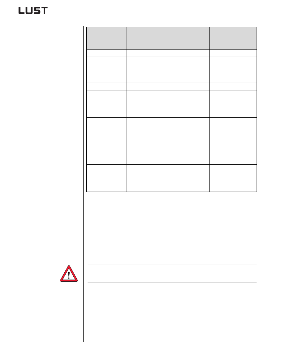
Wire cross-section
.
Device
Inverter module
CDA32.004 1.7 2.5 1 x 10
CDA32.006
CDA32.008
CDA34.003
CDA34.005
CDA34.006 4.2 2.5 3 x 10
CDA34.008
CDA34.010
CDA34.014
CDA34.017
CDA34.024
CDA34.032
CDA34.045
CDA34.060
CDA34.072
CDA34.090
CDA34.110
CDA34.143
CDA34.170
CDA34.250
Table 3.2 Wire cross-sections and mains fuses (VDE0298 must be
connected load
[kVA]
2.3
3.0
1.6
3.0
5.7
7.3
10.2
12.4
17.5
23.3
32.8
43.8
52
65
80
104
124
145
173
observed)
Max. possible wire
cross-section of
terminals [mm²]
2.5
2.5
4.0
10
25
50
Threaded bolt M8
Threaded bolt M8
Recommended mains
fusing (gL)
[A]
1 x 16
1 x 16
3 x 10
3 x 10
3 x 10
3 x 16
3 x 20
3 x 25
3 x 35
3 x 50
3 x 50
3 x 63
3 x 80
3 x 100
3 x 125
3 x 160
3 x 200
3 x 250
3 x 315
3.5 DC network
CDA3000 Operation Manual
The inverter modules run in regenerative operation (braking) in a DC
network feed power into the DC network which is consumed by the motordriven inverter modules.
DC network operation of s everal inverter modules minimizes the power
consumption from the mains and external braking resistors can be
eliminated where appropriate.
Note: It is essential that a DC network operation be checked at the
project planning stage. Please consult your project engineer.
3-8
Page 25
3 Installation
3.6 Braking resistor (RB)
In regenerative operation, e .g. braking the drive, the motor feeds energy
back into the inverter. This increases the vo ltage in the DC-link. If the
voltage exceeds a threshold value, the internal braking transistor is
activated and the regene rated power is converted into heat by way of a
braking resistor.
The switching transistor is installed as standard. The design of the
external braking resistor depends on a number of drive factors:
for example the load to be moved, the required dy namics of the drive or
the braking and cycle duration.
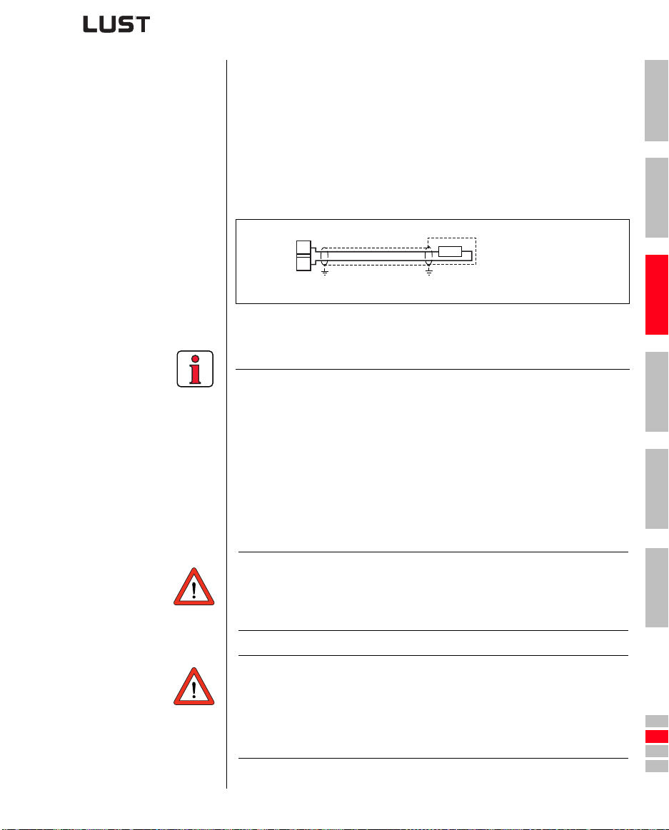
L+
RB
X1
Figure 3.6 Braking resistor connection
Note the following points:
• The design of the braking resistor must be clarified at the project
planning stage.
• For details of the permissible minimum ohmic resistance of an
externally installed braking resistor for the individual inverter
modules refer to Appendix A.2.
• Details of the peak braking power with an internal braking resistor
(only with version CDA34 ...,Wx.x,BR) are also given in Appendix
A.2.
For further information please consult your project engineer.
RB
1
2
3
4
5
CDA3000 Operation Manual
Attention: In device version CDA3X.xxx, Wx.x, BR
the braking resistor is built-in. No additional braking resistor
may be connected to terminals X1 /L+ and RB; this would
damage the inverter module.
Attention: At warning message „excessive temperature at inverter heat
sink“ the connected device must be separated from the
mains, because an overvoltage of the m a ins leads to an
overload of the braking resistor. Please integrate one of the
digital outputs into your control concept, e.g. set OSDxx to
WOTI (Warning heat sink temperature of device).
3-9
A
DE
EN
FR
IT
ES
FR
Page 26
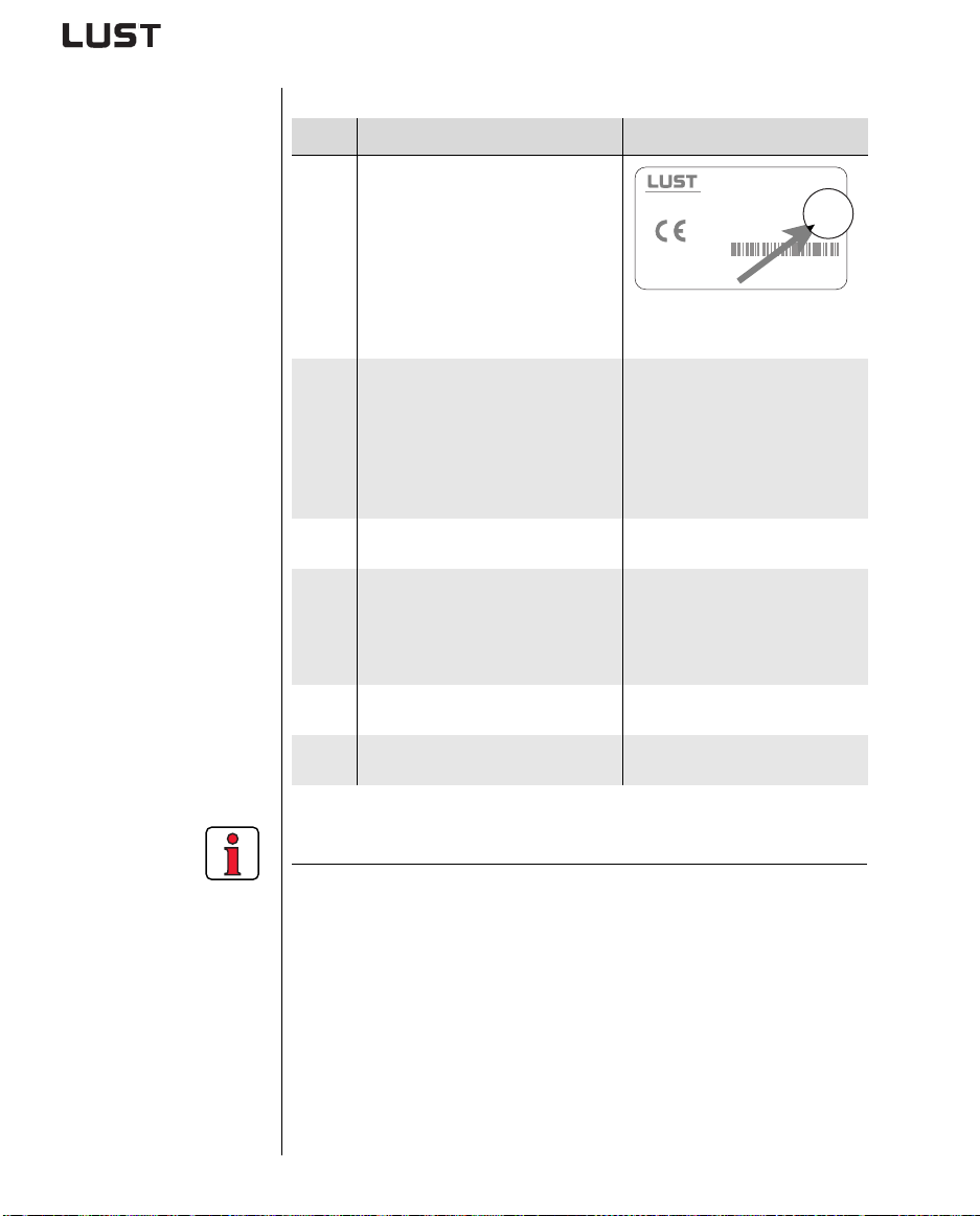
3 Installation
3.7 Control connections
Step Action Comment
Check whether your inverter module is
fitted
a modified software package
(>V100.x)
(standard software = Vx.xx-xx)
1
If this is the case, the control terminal
assignment is different. Please
contact your project engineer with
regard to wiring and commissioning!!
Check whether you already have a
MARTCARD or a DRIVEMANAGER data
S
Position of software name plate see
section 3.1 Page 3-2
Bulk customers
Type: CDA32.004,C1.0
ANTRIEBSTECHNIK
Software: V
D- 35633 Lahnau
CS:
Data Set:
SN.: 99120442
set with a complete device setup.
If this is the case, the control terminal
2
assignment is different. Please
contact your project engineer to obtain
the terminal assignment!
Choose a terminal assignment.
3
Wire the control terminals with
shielded cables.
The only essential signals are the
4
ENPO signals and a start signal
(STR or STL).
Keep all contacts open
5
(inputs inactive).
Check all connections again!
6
For details of how to load the data
set into the inverter module refer to
section 4.6.
see 3.7.1 “Choice of terminal
assignment”
Ground the cable shields over a
wide area at both ends.
Wire cross-section maximum
1.5 mm² or two cores per terminal
each 0.5 mm²
Continue with commissioning in
section 4.
C1D1
1xx.x
CDA3000 Operation Manual
Note the following points:
• Always wire the control terminals with shielded cables.
• Lay the control cables separately from the mains lead and motor
cable.
• The CDA3000 Application Manual presents more drive solutions.
• For all shielded connections a cable type with double copper
braiding with 60-70 % coverage must be used.
3-10
Page 27
3 Installation
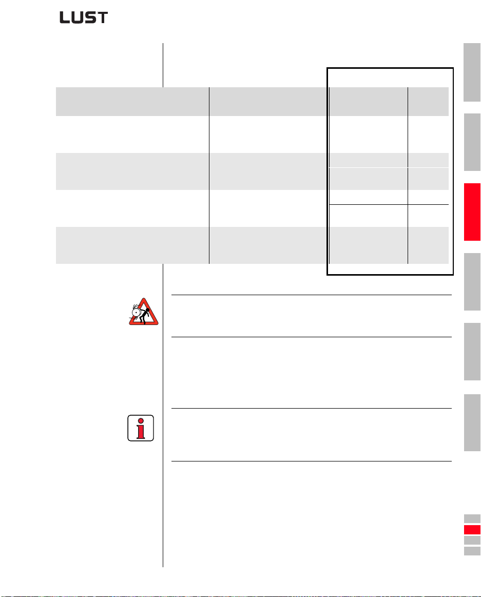
3.7.1 Choice of terminal assignment
Typical applications Control method Terminal assignment
• Project planning and commissioning are
already complete.
• Loading of an existing data set.
• Pump, fan and extruder drivers and traction
and lifting drives with low dynamics
• Multi-motor operation
• Dynamic traction and rotational drives
• Applications with dynamic load
surges
• Dynamic traction, lifting and rotational
drives with speed control
• With encoder feedback
Attention: With the SFC motor control mode (Sensorless Flux Control)
Selection
Continued
on
Obtain the terminal
Serial commissioning
Voltage Frequency Control (VFC)
Sensorless Flux Control (SFC)
- Only for asynchronous motor
Field-Oriented Regulation (FOR)
- Only for asynchronous motor
no lifting drives and no applications with regenerat ive load
torque1) can be operated at present.
assignment from your
project engineer.
Assignment 1 Page 3-13
Assignment 2 Page 3-14
Assignment 1 Page 3-13
Assignment 2 Page 3-14
Assignment 3 Page 3-15
Page 4-12
Commis-
sioning
1
2
3
4
CDA3000 Operation Manual
1)
All machinery counteracts the drive with a static torque. The static
torque is generally termed load torque. If this load torque acts in the
direction of movement, such as in lifting mechanisms, during lowering,
then the term “regenerative load torque” is used.
Note: During operation intensive lo ad peaks or unintentional
cancelling of the start effects in a loss of stator flow control of
the SFC-control. So that a current overload shut-off or
uncontrolled movements can occur.
3-11
5
A
DE
EN
FR
IT
ES
FR
Page 28
3 Installation
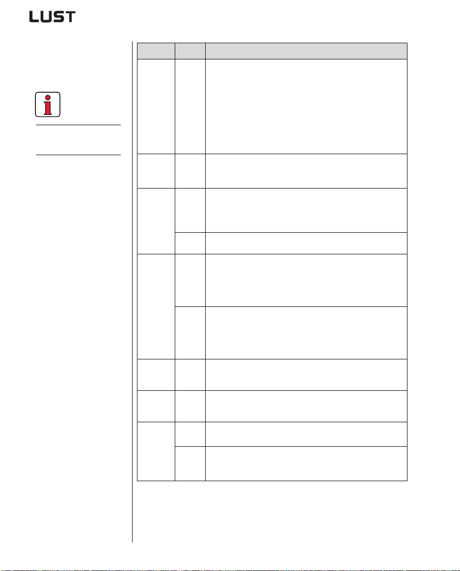
The terminal scan
cycle is 1 ms.
3.7.2 Specification of control terminals
Des. Specification
Analog
inputs
ISA00
ISA01
• ISA00: U
= +10 V DC, ±10 V DC, I
IN
switchable by software
= (0) 4-20 mA DC,
IN
• ISA01: UIN = +10 V DC
• Tolerance U: ± 1% v. M., I: ±1% of MV
• 24 V digital input, PLC-compatible
• Switching level Low/High: <4.8 V / >8 V DC
• Resolution 10-bit
•R
=110kΩ
in
• Floating against digital ground
Analog
output
Digital
inputs
OSA00 • Tolerance U: ±2.5% of MV
•U
ISD00
ISD01
ISD02
ISD03
=+10 V DC, R
out
•I
=5 mA, short-circuit-proof
max
• PLC-compatible
• Switching level Low/High: <5 V / >18* V DC
•I
at 24 V = 10 mA
max
•R
= 3 kΩ
IN
OUT
=100 Ω
ENPO • Power stage enable = High level
• Specification as ISDxx
Digital
outputs
OSD00 • Short-circuit-proof
• PLC-compatible
•I
= 50 mA
max
• Protection against inductive load
• High-side driver
OSD01 • Short-circuit-proof with 24V supply from inverter module
• PLC-compatible
•I
= 50mA
max
• No internal freewheeling diode; provide external protection
• High-side driver
Relay
output
OSD02 • Relay 48 V / 1 A AC, changeover contact
• Usage category AC1
• Operating delay approx. 10 ms
Motor
temperature
Voltage
supply
PTC1/ 2 • max. 12 V DC, measuring range 100 Ω - 15 kΩ
• Suitable for PTC to DIN 44082 or temperature sensor KTY84-130
(tolerance band yellow) or thermostatic circuit-breaker
+10.5V • Reference voltage UR =10.5 V DC, short-circuit-proof
•I
= 5 mA
max
+24V • Auxiliary voltage UV = 24 V DC, short-circuit-proof
•I
= 200 mA (overall, also includes driver currents for outputs
max
OSD0x)
*In the range >5 V / <18 V the response of the inputs is undefined.
CDA3000 Operation Manual
3-12
Page 29
3 Installation
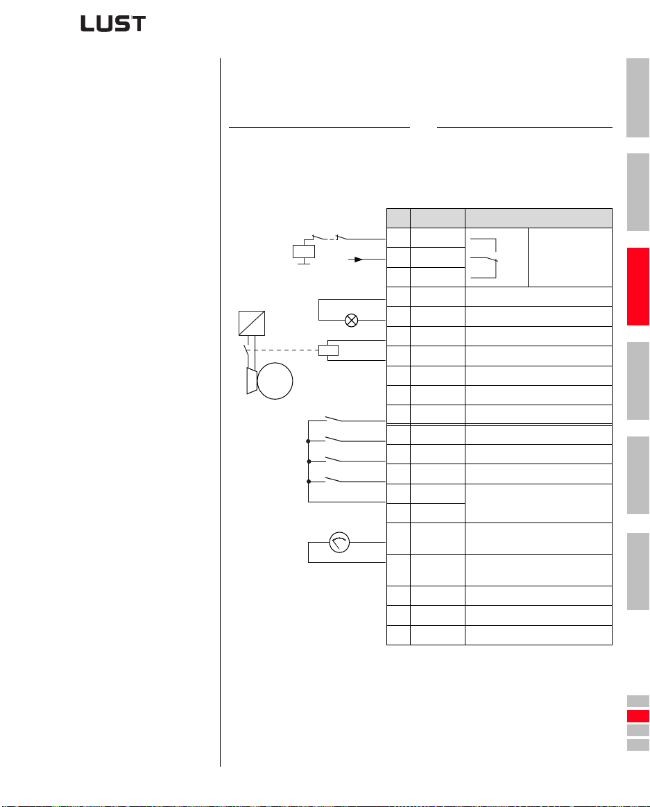
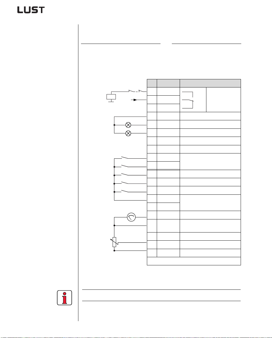
3.7.3 Terminal assignment 1
Terminal assignment in factory setting
Preset solution “Clock drive, quick/slow jog”.
Features Parameter
• Quick jog/slow jog driving profile
with two directions of rotation
• Output for motor holding brake
~
K0
-
M
3~
+24V
H1
K1
S1
STL
STR
ENPO
0 ... 10 V
N1
X2 Des. Function
20 OSD02
19 OSD02
18 OSD02
17 DGND Digital ground
16 OSD01 “Reference reached” message
15 OSD00 Output for motor holding brake
14 DGND Digital ground
13
12 ISD03 Not assigned
11 ISD02 Selection of slow jog
10 ISD01
9 ISD00 Start/Stop quick jog clockwise
8 ENPO Power stage hardware enable
7
6
5 OSA00
+
-
4 AGND
3 ISA01 Not assigned
2 ISA00 Not assigned
1
152-ASTER = DRV_1
14
11
12
U
Auxiliary voltage 24 V
V
Start/Stop quick jog anti-clockwise
U
V
Auxiliary voltage 24 V
U
V
Actual frequency 0 ... FMAX
0 ... 10 V corresponds to
Analog ground
0 ... 10 V corresponds to
U
Reference voltage 10.5 V, 5 mA
R
1
2
Relay contact
for “Ready”
message
3
4
5
A
CDA3000 Operation Manual
Figure 3.7 C ontrol terminals, traction drive without encoder evaluation
3-13
DE
EN
FR
IT
ES
FR
Page 30
3 Installation
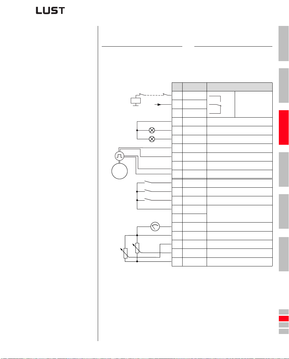
3.7.4 Terminal assignment 2
Preset solution “Analog reference and fixed frequency”.
Features Parameter
• Analog speed input for two directions
• Selection of fixed frequencies via
binary coding of switches S1/S2
152-ASTER = ROT_6
• Functionally compatible with VF1000
X2 Des. Function
K0
+24V
19 OSD02
18 OSD02
20 OSD02
14
11
12
Relay contact
for “Ready”
message
17 DGND Digital ground
H2
H1
16 OSD01 “Standstill” message
15 OSD00 “Reference reached” message
14 DGND Digital ground
U
0 ... 10 V
N1
S2
S1
STL
STR
ENPO
13
12 ISD03
11 ISD02
10 ISD01
9 ISD00 Start/Stop quick jog clockwise
8 ENPO Power stage hardware enable
7
6
5 OSA00 Actual frequency 0 ... FMAX
+
4 AGND
-
Auxiliary voltage 24 V
V
Choice of fixed frequency
(binary coded) *
Start/Stop quick jog anti-clockwise
U
V
Auxiliary voltage 24 V
U
V
Analog ground
0 ... 10 V corresponds to
3 ISA01 Not assigned
R1
≥ 10 kΩ
2 ISA00 Reference 0 V ... + 10 V
U
1
*Function see section 4.3, Ta bl e 4.1
Reference voltage 10.5 V, 5 mA
R
Figure 3.8 Terminal assignment, rotational drive without encoder evaluation
CDA3000 Operation Manual
Note: The terminal assignment applies to firmware V3. 1 and higher
3-14
Page 31
3 Installation
3.7.5 Terminal assignment 3
Preset solution “Analog reference + correction, with rotary encoder”.
Features Parameter
• Analog speed input for two
directions with speed correction
• Encoder evaluation
152-ASTER = ROT_2
X2 Des. Function
K0
(1)
N2
M
3~
R2
≥ 10 kΩ
(1) Only encoder type HTL (24V supply) usable. The encoder is evaluated only in control
mode FOR. For notes on the rotary encoder see Figure 3.10.
Figure 3.9 Control terminal assignment, rotational drive with encoder
+24V
H2
H1
N1
≥ 10 kΩ
R1
evaluation
STL
STR
ENPO
0 ... 10 V
20 OSD02
19 OSD02
18 OSD02
17 DGND Digital ground
16 OSD01 “Reference reached” message
15 OSD00 “Standstill” message
-
14 DGND Digital ground
+
13
B
12 ISD03 Encoder track B
A
11 ISD02 Encoder track A
10 ISD01 Start/Stop anti-clockwise
9 ISD00 Start/Stop clockwise
8 ENPO Power stage hardware enable
7
6
+
5 OSA00 Actual frequency 0 ... FMAX
4 AGND Analog ground
-
3 ISA01 Correction reference* 0 V ... +10 V
2 ISA00 Reference 0 V ... + 10 V
1
14
11
12
U
Auxiliary voltage 24 V
V
U
V
Auxiliary voltage 24 V
U
V
U
Reference voltage 10.5 V, 5 mA
R
Relay contact
for “Ready”
message
1
2
3
4
5
A
CDA3000 Operation Manual
Correction reference*: For a description of the function refer to the
CDA3000 Application Manual.
3-15
DE
EN
FR
IT
ES
FR
Page 32
3 Installation
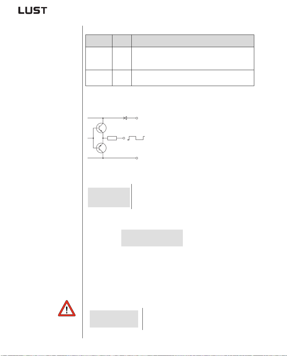
3.7.6 Encoder
Maximum number of lines of
encoder
Specification of encoder connections:
Des. Specification
Digital
inputs
Connecting
cable
ISD02
ISD03
- • Screened twisted-pair cable with approx. 60 nF/km
•f
= 150 kHz
limit
• PLC-compatible (L = < 5 V, H = > 18 V)
• Current consumption (encoder) max. 80 mA
• Cable length max. 30 m
A HTL encoder with 24 V supply can be c onnected to terminals X2/11
and 12. Permissible pulse count s are in the range from
512, 1024 ...to 16384 pulses per rev
+
NPN
PNP
-
Figure 3.10 Block diagram, HTL ou tput circuit
6
LR
n
max
max
LR
max
910
⋅
---------------=
n
max
(2n where
A
Maximum number of lines of encoder in
=
pulses per rev.
=
Maximum speed of motor in rpm
n = 5 to 14
32, 64, 128, 256,
).
Example of n
Calculated: pulses per rev.
= 6000 rpm:
max
LR
max
6
910
⋅
--------------- 1500==
6000
Selected: An encoder with 1024 pu ls es per rev.
Reasoning: 1500 pulses per rev. is not programmable - the nearest
10
possible value is 1024 pulses per rev. (binary 2
)
Minimum motor speed Formula for calculating the minimum motor speed depending on the
encoder lines per revolution so that one pulse of the encoder can be
evaluated each scan cycle of the inverter module.
Number of lines of encoder in pulses per rev.
Minimum speed of motor in rpm
=
min
3-16
CDA3000 Operation Manual
LR =
1
3000
---------
-----------
n
min
LR
⋅=
min
n
Page 33
4 Commissioning
4 Commissioning
4.1 Choice of commissioning .......................................4-1
4.2 Standard commissioning ........................................4-2
4.3 KEYPAD commissioning ...........................................4-4
4.4 DRIVEMANAGER commissioning ................................4-6
4.5 Direction check .....................................................4-11
4.6 Serial commissioning ...........................................4-12
4.6.1 Serial commissioning with KEYPAD .....................4-12
4.6.2 Serial commissioning with DRIVEMANAGER ..........4-14
4.7 Operation with KEYPAD KP200 ...............................4-15
4.8 Operation with DRIVEMANAGER ...............................4-18
4.9 Parameter list (selection) .....................................4-19
1
2
3
4.1 Choice of commissioning
CDA3000 Operation Manual
Attention: Commissioning must only be carried out by qualified
electricians who have undergone instruction in the necessary
accident prevention measures.
Standard commissioning
KEYPAD commissioning
DRIVEMANAGER commissioning
Serial commissioning
The device can be put into operation with its factory
settings, without need of any other aids.
The KEYPAD enables you to preset a number of basic
parameters, such as rotating field limitation (FMAX),
acceleration/deceleration ramps (ACCR/DECR) or fixed
frequencies (FFIX) etc.
The “DRIVEMANAGER 3.0” PC user interface enables you
to customize your drive tasks in a user-friendly way.
To commission several identical drives, for example,
you can transfer the data set of the first drive via K
MARTCARD or via DRIVEMANAGER to the following
with S
drives.
4-1
4
5
A
EYPAD
DE
EN
FR
IT
ES
FR
Page 34
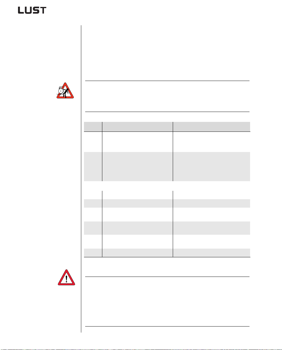
4 Commissioning
Start drive
1) Factory setting from BG1 to BG5
(15 kW) = 20 Hz/s, from BG6
(22 kW) to BG8 = 5 Hz/s
4.2 Standard commissioning
This mode of commissioning is based on the factory setting.
Precondition:
• Inverter module is fully connected.
• Recommended IEC standard motor (see section A.2) is connected.
• Control terminals are wired as per terminal assignment 1,
see page 3-13.
Attention: Make sure that the rotating drive of your machine cannot
cause any damage during commissioning (s uch as by
overshooting a stop limit) and that there are no personnel
inside the danger zone.
.
Step Action Note
Connect the mains power supply to
1
the inverter module.
Check that your drive can be run at
the factory set (FS) rotating field
2
frequency and ramps.
Close ENPO contact. Enables power stage.
3
Set drive to slow jog Close S1 = slow jog
4
Start drive by closing STL or STR
5
contact.
Check direction of rotation of motor
6
shaft
Brake drive by opening start
7
contact.
After power-on, inverter module
performs a self-test (lasting approx.
1... 3 s).
Quick jog = 50 Hz
Slow jog = 20 Hz
Acceleration ramp
Deceleration and stop ramp
1)
1)
STL = start anti-clockwise
STR = start clockwise
see section 4.5 “Direction check”
Drive brakes down to standstill.
Open ENPO contact. Safely disables power stage.
Commissioning is completed.
CDA3000 Operation Manual
Note: If the connected IEC standard motor differs by more than two
power classe s from the rated power outpu t of the inverter
module, “D
RIVEMANAGER commissioning” wi th automatic
motor identification should be carried out, see section 4.4.
The same applies to commissioning of special motors such
as reluctance, synchronou s or HF m otors. Please consult
your project engineer.
4-2
Page 35
4 Commissioning
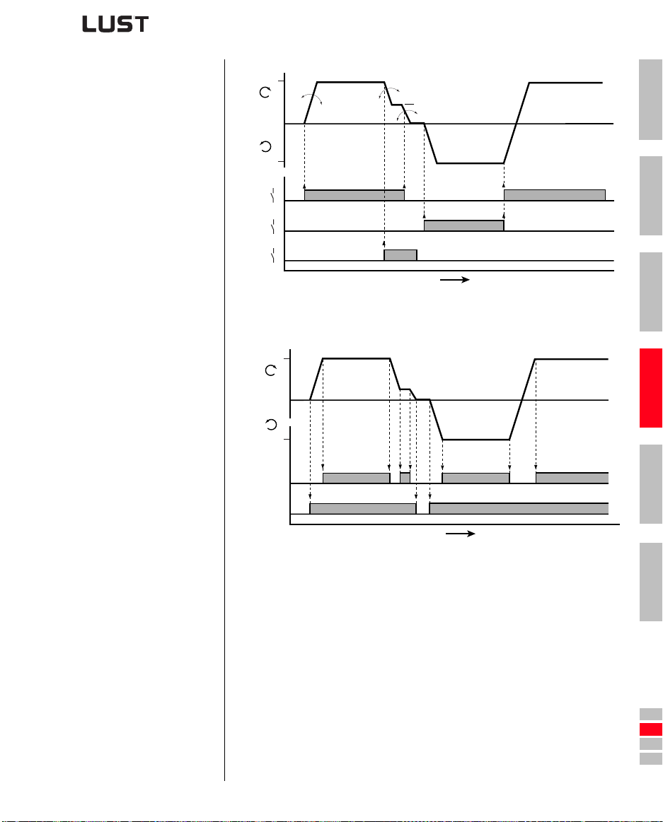
Input signals of
terminal assignment 1
(152-ASTER = DRV_1)
Output signals of
terminal assignment 1
(152-ASTER = DRV_1)
FMAX
f [Hz]
FMAX
STR
STL
S1
0
1
0
1
0
1
0
303-FMAX1
590-ACCR1
592-DECR1
270-FFIX1
594-STPR1
303-FMAX1
t [s]
Figure 4.1 Example of a quick/slow jog driving profile for two directions
FMAX
0
f [Hz]
FMAX
1
2
3
4
CDA3000 Operation Manual
1
H1
0
1
K1
0
t [s]
Figure 4.2 Output signals depen de nt on driving profile
H1 = Reference reached; K1 = Motor holding brake output signal
4-3
5
A
DE
EN
FR
IT
ES
FR
Page 36
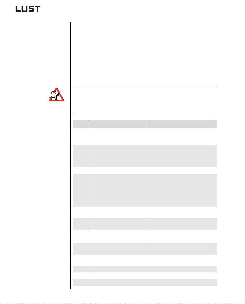
4 Commissioning
Start drive
1) Factory setting from BG1 to BG5
(15 kW) = 20 Hz/s, from BG6
(22 kW) to BG8 = 5 Hz/s
4.3 KEYPAD commissioning
CDA3000 Operation Manual
This mode of commissioning is performed with the KEYPAD control unit
(accessory order designation: KP200). It enables a number of basic
parameters to be adjusted directly.
Precondition:
• Inverter module is fully connected.
• Recommended IEC standard motor (see section A.2) is connected.
• Control terminals are wired as per terminal assignment 2,
see page 3-14.
• KP200 is plugged in.
Attention: Make sure that the rotating drive of your machine cannot
cause any damage during commissioning (s uch as by
overshooting a stop limit) and that there are no personnel
inside the danger zone.
.
Step Action Note
Connect the mains power supply to
1
the inverter module.
Check that your drive can be run at
the factory set (FS) rotating field
2
frequency and ramps.
If this is not possible, change the parameters with the KEYPAD
Press the start/enter key once to
enter subject area _11UA and press
3
the start/enter key again to select
the parameter you want to change.
Select the preset solution
4
“Rotational drive 6”
Press “stop/return” to return to “Menu”.
5
Save setting by pressing both cursor keys simultaneously for 3 seconds.
Close ENPO contact and set a low
1
reference value with R1.
Start drive by closing STL or STR
2
contact.
Check direction of rotation of motor
3
shaft
Open start contact. Drive brakes down to standstill.
4
Open ENPO contact. Safely disables power stage.
5
Commissioning is completed.
After power-on, inverter module
performs a self-test (lasting approx.
1... 3 s).
Rotating field frequency (FMAX) = 50Hz
at reference value (R1) = 10 V
Acceleration ramp
Deceleration and stop ramp
FMAX 303-FMAX1
Acceleration ramp 590-ACCR1
Deceleration ramp 592-DECR1
Stop ramp 594-STPR1
Adapt parameter using cursor keys, confirm
change with “start/enter” key.
Parameter 152-ASTER
to “ROT_6”
ENPO enables power stage.
Motor accelerates to preset reference
see section 4.5 “Direction check”
1)
1)
4-4
Page 37
4 Commissioning
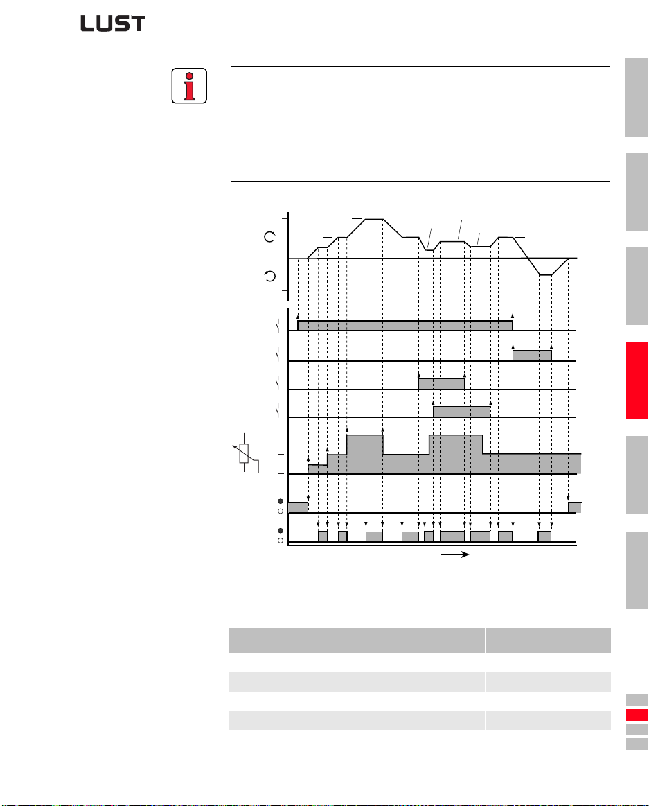
Input signals
terminal assignment 2
(152-ASTER = ROT_6)
Output signals
terminal assignment 2
(152-ASTER = ROT_6)
H1 = Reference reached
H2 = Standstill
Note: If the connected IEC standard motor differs by more than two
power classes from the rated power output of the inverter
module, “D
RIVEMANAGER commissioning” with automatic
motor identification should be carried ou t, see section 4.4.
The same applies to commissioning of special mot ors such
as reluctance, synchronous or HF m otors. Please consult
your project engineer.
1
0
1
0
1
0
1
0
1
0
303-FMAX1
R1
R1
FFTB3
FFTB1
R1
FFTB2
FMAX
f [Hz]
FMAX
STR
STL
S1
S2
10 V
R1
5 V
0 V
H2
H1
t [s]
Figure 4.3 Signal characteristic dependent on driving profile
(ASTER=ROT_6)
2
R1
3
4
5
A
CDA3000 Operation Manual
Reference S2 (ISD03) S1(ISD02) ISA00
Analog reference at input ISA00 (R1) 0 0 active
Table frequency 601-FFTB1 (FS = 10Hz) 0 1 inactive
Table frequency 602-FFTB2 (FS = 15Hz) 1 0 inactive
Table frequency 603-FFTB3 (FS = 20Hz) 1 1 inactive
Table 4.1 Scaling of binary coded inputs ISD02 (S1) and ISD03 (S2)
4-5
DE
EN
FR
IT
ES
FR
Page 38
4 Commissioning
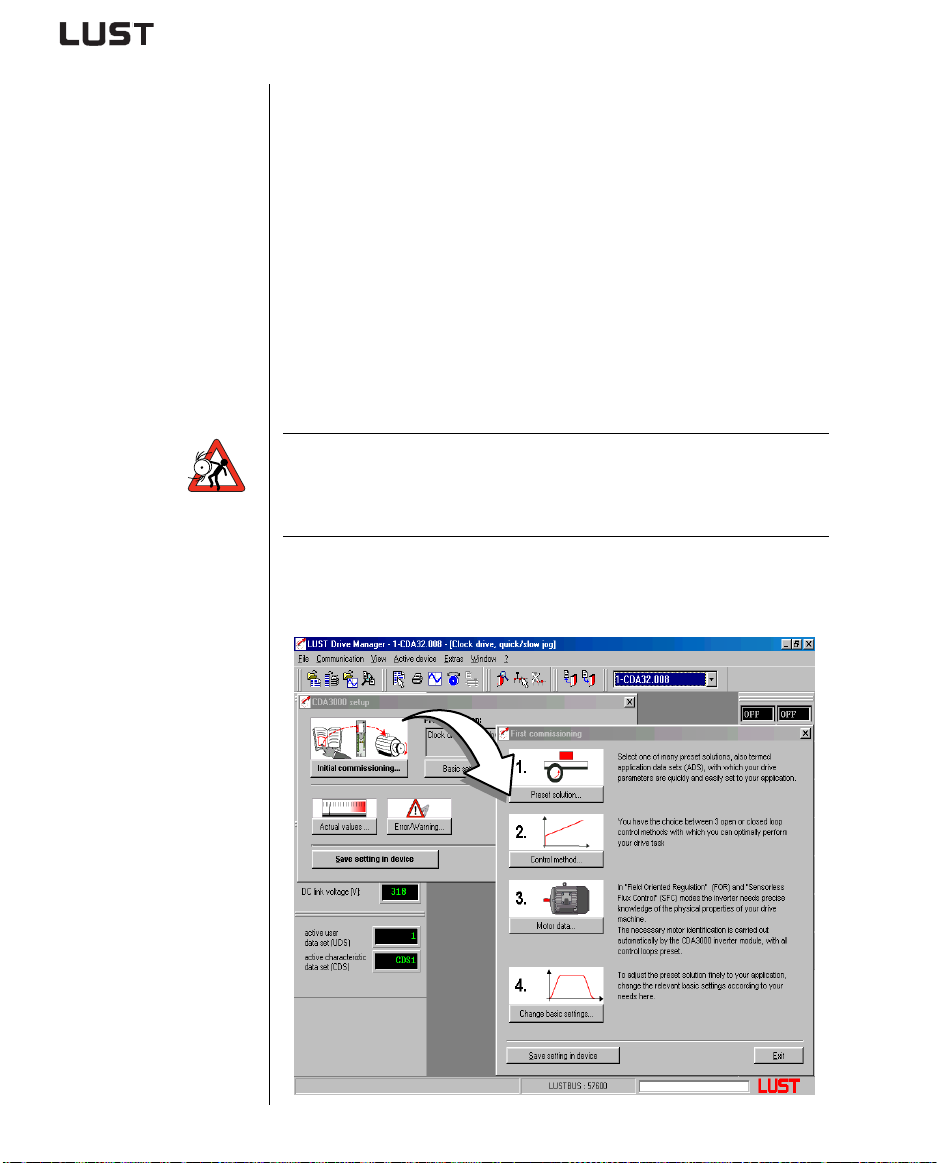
4.4 DRIVEMANAGER commissioning
The DRIVEMANAGER as from version 3.0 makes commissioning easier,
especially the adaptation of your drive. It should be used specifically
when commissioning with “SFC” or “FOR” mode.
The following is an illustration of the commissioning proce dure based on
the example of the preset solution ROT_2.
Precondition:
• Inverter module is fully connected.
• Control terminals are wired as per terminal assignment 3,
see page 3-15.
• The motor with encoder planned for the applicat ion is correctly
connected.
• All data of the motor (rating plate data) and the encoder are
available.
Attention: Make sure that the rotating drive of your machine cannot
cause any damage during commissioning (s uch as by
overshooting a stop limit) and that there are no personnel
inside the danger zone.
The main window contains the “Initial commissioning” button. Click on it to
open up the Wizard, which will guide you in four steps through the
commissioning process.
CDA3000 Operation Manual
4-6
Page 39
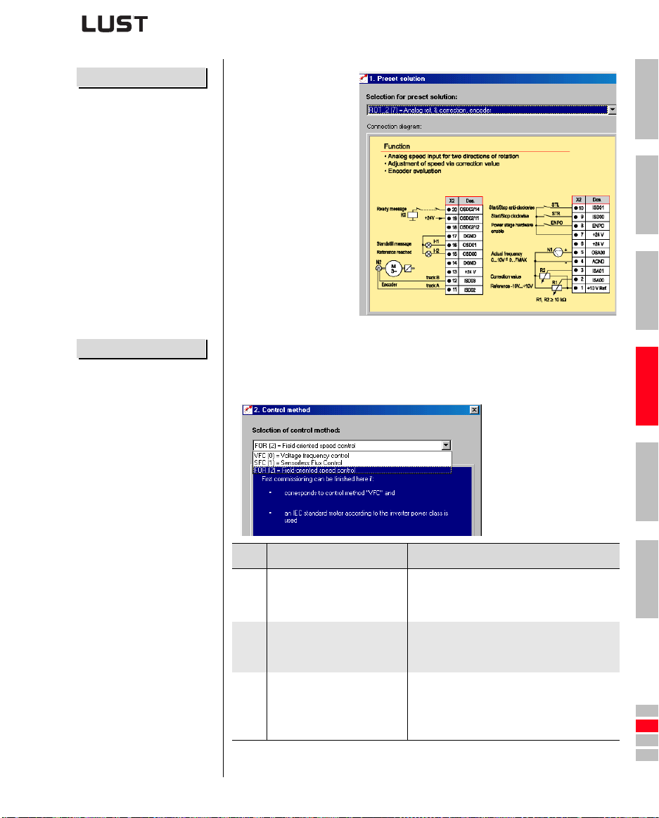
1. Preset solution...
In this window you
select the terminal
assignment required
for control of your
application.
As a check, the
terminal diagram and
specimen
applications are
illustrated.
For our example
please set ROT_2.
4 Commissioning
1
2
3
2. Control method...
CDA3000 Operation Manual
Different control methods have special advantages depending on the
application. Three modes of control are available.
For our example please set FOR(2).
Meaning Application
Voltage Frequency Control
VFC
(factory setting)
Sensorless Flux Control
SFC
• Only for asynchronous
motors
Field Oriented Regulation
• Encoder is necessary
FOR
• only for asynchronous
motors
Table 4.2 Choice of control method
• Pump, fan and extruder applications
• Traction and lifting drive with low dynamics
• Multi-motor operation
• Dynamic traction, lifting and rotational
drives
• Drives with dynamic load surges
• Dynamic traction and rotational drives
• Speed control with encoder feedback
4-7
4
5
A
DE
EN
FR
IT
ES
FR
Page 40
4 Commissioning
3. Motor data...
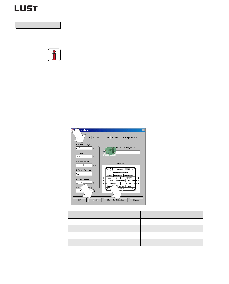
By way of the automatic motor identification the characteristic data of IEC
standard motors and ASM servomotors can be determined. The
precondition for problem-free identification is that the rating plate data are
present and correctly entered.
Note: The data of the motor nominal point (max. rated power output
of the motor) must always be en tered. In 87 Hz applications
(motor: 230 V, delta configuration) the converted 87 Hz data
must be entered. For more information refer to the CDA3000
Application Manual.
For our example this setting is required.
Following identification of the motor, all control loops are automatically
computed and the necessary parameter adjustments made.
Precondition:
• The motor is connected.
• Hardware enabled ( = ENPO contact clo sed).
1
CDA3000 Operation Manual
3
Step Action Note
Enter motor data see your motor type designation
1
Click on “Start identification” button Takes approx. 3 min.
2
Apply setting Values are transferred to device
3
Re-open ENPO contact on device Power stage safely disabled
4
Motor identification is complete
2
4-8
Page 41
4 Commissioning
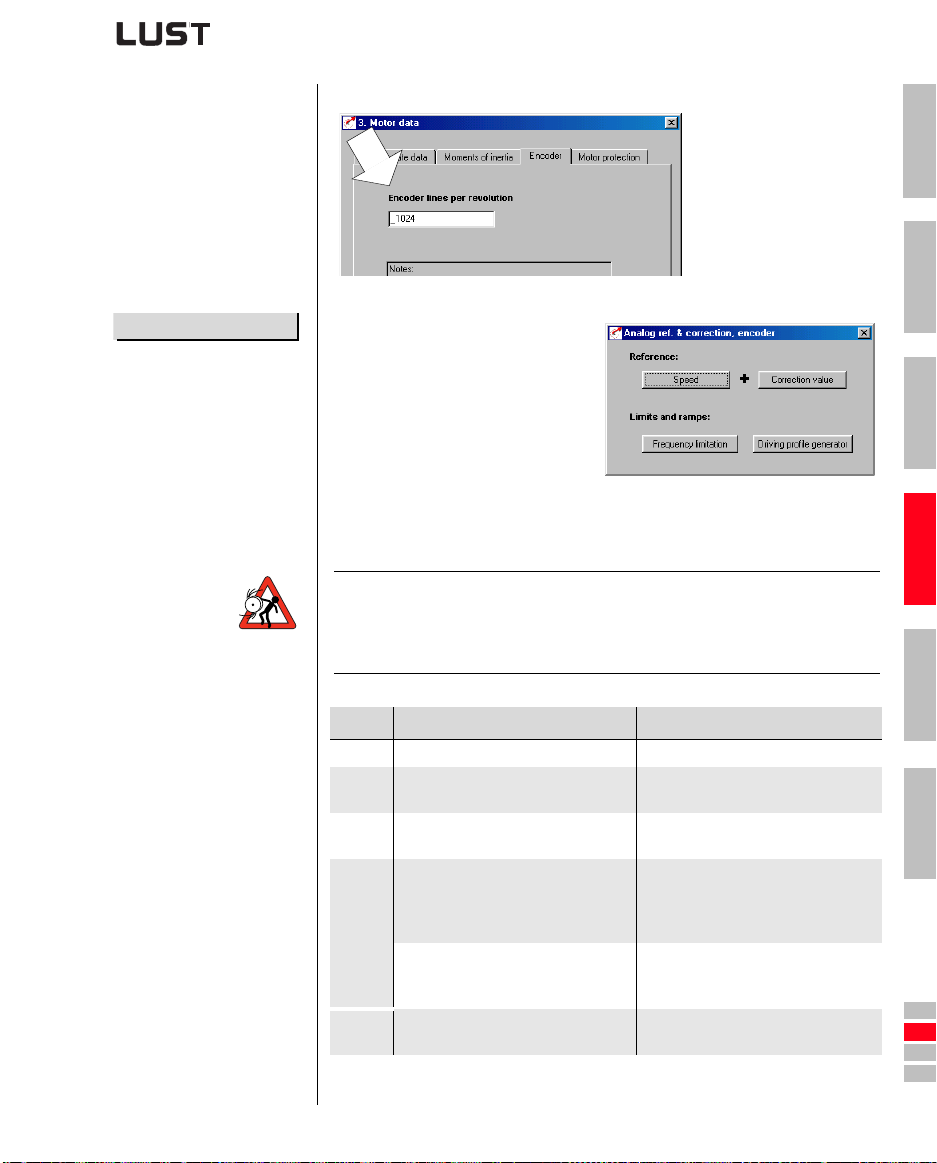
Set lines per revolution of
encoder used
4. Change basic settings...
This setting is only required in “FOR” mode.
In the last step you can adapt the
basic setting of the preset solution
to your application.
The setting options vary according
to the selected preset drive
solution (here the example for
ROT_2).
Test setting
Attention: Make sure that the rotating drive of your machine cannot
cause any damage during commissioning (such as by
overshooting a stop limit) and that there are no personnel
inside the danger zone.
1
2
3
4
CDA3000 Operation Manual
Step Action Note
Close ENPO contact. ENPO active enables power stage.
1
Set low reference with R1.
2
Start drive by closing STL or STR
3
contact.
If the motor runs uncontrolled and does
not accelerate up to the preset
reference, stop the drive (open STL or
STR contact).
4
Motor accelerates up to preset
, commissioning can be
reference
continued.
Set correction reference with R2
5
see section “3.7.5 Terminal
assignment 3”
Motor accelerates to preset reference
Check phase position, motor and
encoder connections, see section 4.5
“Direction check”
Drive accelerates further by amount
of correction reference.
4-9
5
A
DE
EN
FR
IT
ES
FR
Page 42
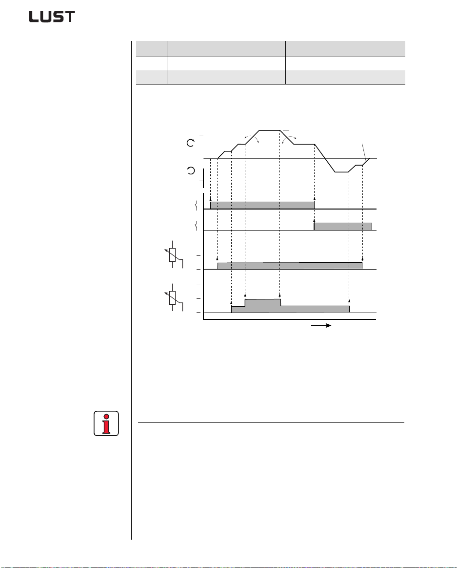
Input signals
4 Commissioning
Step Action Note
Brake drive by opening start contact. Drive brakes down to standstill.
6
Open ENPO contact. Safely disables power stage.
7
Commissioning is completed.
FMAX
590-ACCR1
0
f [Hz]
FMAX
1
STR
0
1
STL
0
10 V
R1
5 V
0 V
10 V
R2
5 V
0 V
303-FMAX1
592-DECR1
594-STPR1
t [ms]
Figure 4.4 Example of a driving profile for two directions with correction
reference (R2), 152-ASTER = ROT_2
FOR setting FOR is preset, and requires no further optimization for standard
applications.
Note:
For more detailed information on optim izing
• the speed control loop
refer to the CDA3000 Application Manual.
CDA3000 Operation Manual
4-10
Page 43
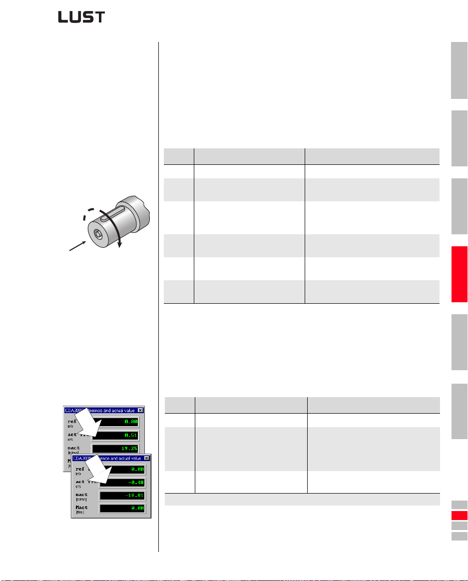
4.5 Direction check Precondition:
• Inverter module is fully connected.
• The motor planned for the application is cor rectly connected.
• Device set to VFC mode = Voltage Frequency Control (factory
setting).
• Enter a low reference value, e.g. slow jog.
1. Test phase position of motor
connections.
Step Action Note
Close ENPO contact. ENPO active enables power stage.
1
Start drive by closing STR
2
contact.
Check direction of rotation of
3
drive.
1)
(2)
If the direction matches the actuation, the test is completed.
Brake drive by opening start
4
contact.
Open ENPO contact.
5
If direction is wrong, check phase
6
position of motor connections.
4 Commissioning
Motor accelerates to preset reference
With STR active, motor rotates
clockwise (2)
(1) Direction of view.
Drive brakes down to standstill.
ENPO inactive safely disables power
stage.
Also check the control connections:
STR > term. X2/9 (ISD00)
1
2
3
4
2. Test encoder connection Precondition:
• Inverter module is fully connected.
• The motor with encoder planned for the application is correctly
connected.
• Device set to FOR mode = Field Oriented Regulation.
Step Action Note
Open ENPO contact. Power stage safely disabled.
R
L
CDA3000 Operation Manual
1
Turn motor shaft clockwise by hand
(1) Direction of view, (2) Clockwise.
2
If assignment is wrong, check wiring
3
of encoder.
If the direction matches the display, the test is completed.
In status display:
Right (clockwise) = no preceding sign
Left (anti-clockwise) = neg. preceding
sign.
4-11
5
A
DE
EN
FR
IT
ES
FR
Page 44
4 Commissioning
4.6 Serial commissioning
4.6.1 Serial
commissioning
EYPAD
with K
Save data set to SMARTCARD
Apply this mode of commissioning if you want to put several identical
drives into operation (serial co mmissioning). The sa me inverter t ype and
motor must be set for each drive in an identical application.
If you already have a complete data set, skip the subsection headed
“Save data set to S
device to file” (with D
MARTCARD” (with KEYPAD) or “Save data set from
RIVEMANAGER).
Note: Do not load the firmware V180.x (for inverter modules in
execution HF) in the standard inverter modul . By loading the
firmware the error message E-COPU39 will be signalised
one-time by a flashing code of indication H1.
Precondition:
• All inverter modules are fully connected.
• The first drive is already fully commissioned into oper at io n.
Note: The CARD menu can only be selected if the drive is not
active!
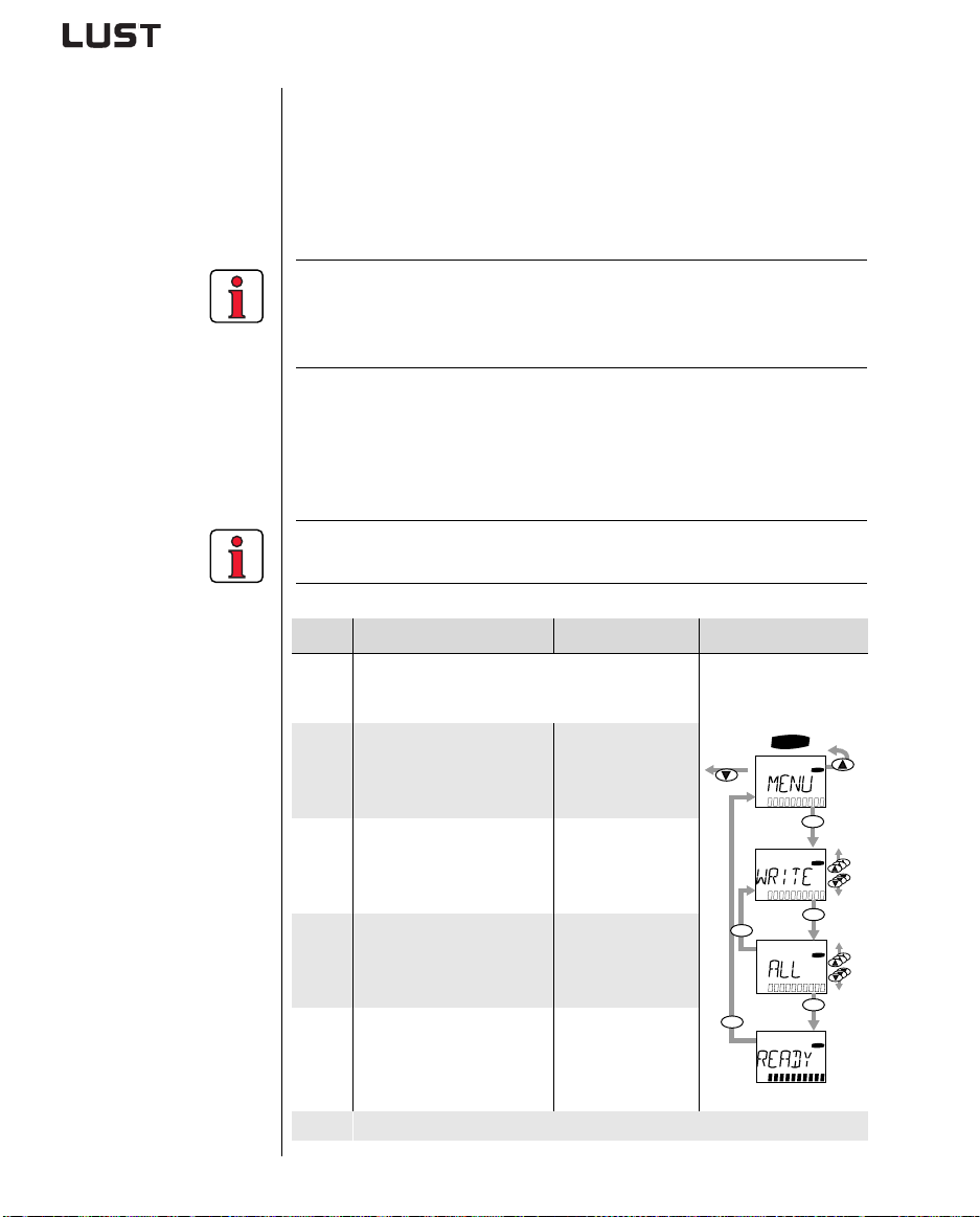
Step Action Note Presentation
Connect the KEYPAD to the inverter module of the
first drive, insert a S
1
MARTCARD and switch on the
power.
CARD
CARD
start
enter
Select the CARD menu.
2
= load/save with
MARTCARD
S
CDA3000 Operation Manual
Choose WRITE. = Save data set
3
Choose ALL and start the
save operation with the
4
start/enter key.
= Complete data set
is saved
= Save operation
READY appears.
5
completed without
error
By this procedure you have written your data set to a SMARTCARD.
4-12
CARD
start
stop
return
stop
return
enter
CARD
start
enter
CARD
Page 45
4 Commissioning
Download data set from
MARTCARD to next inverter
S
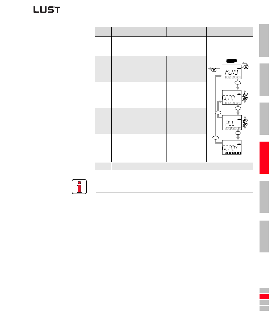
Step Action Note Presentation
Connect the KEYPAD to the inverter module of the
next drive, insert the S
1
MARTCARD with the desired
data set and switch on the power.
Select the CARD menu.
2
Choose READ. = Load data set
3
Choose ALL and start the
load operation with the
4
start/enter key.
= load/save with
S
= Complete data set
is loaded
MARTCARD
CARD
stop
return
stop
return
= Load operation
READY appears.
5
completed without
error
Repeat this procedure on each of the other drives.
Note: Data set is automatically stored in inverter module.
1
CARD
start
enter
2
CARD
start
enter
CARD
3
start
enter
CARD
4
CDA3000 Operation Manual
4-13
5
A
DE
EN
FR
IT
ES
FR
Page 46
4 Commissioning
Save data set from device to
file
Download data set from file
into device
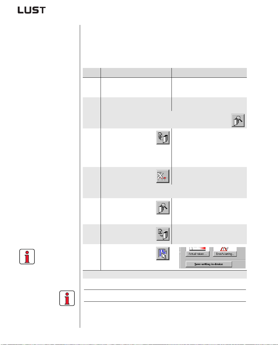
Remember to save
the setting.
4.6.2 Serial
commissioning
with
RIVEMANAGER
D
Precondition:
• All inverter modules are fully connected.
• The first drive is already fully commissioned into oper at io n.
• A PC with installed DRIVEMANAGER user software (V3.0 or higher) is
connected.
Step Action Comment
Connect your PC to the inverter
module of the first drive and switch
1
on the power to the inverter.
Start DRIVEMANAGER.
2
If the connection fails, check the settings in the Tools > Options
menu and try again by way of icon
Save the current data set
, either in the
with icon
parameter database
3
(directory: c:/../userdata) of the
RIVEMANAGER or on a floppy disk
D
(a:/).
Disconnect from all devices
4a
with icon
Connect your PC to the inverter module of the next drive and switch on the
4b
power to the inverter.
With icon establish a link
between the D
5
and the newly connected
device.
With icon load the data set
saved in step 4 into the
6
device.
With icon select the main
window.
7
Save the setting with
button ->
Repeat steps 4 ... 7 on each of the other drives.
RIVEMANAGER
Use a standard serial cable (9-pin DSUB, socket/pin) e.g. LUST accessory
CCD-SUB90x .
Automatically links to the connected
inverter module.
.
With icon the current data set of the
connected device is always saved.
Give the file a name of your choice.
The data set is stored in the device as
user data set 1.
CDA3000 Operation Manual
For more information refer to the DRIVEMANAGER Manual.
4-14
Page 47
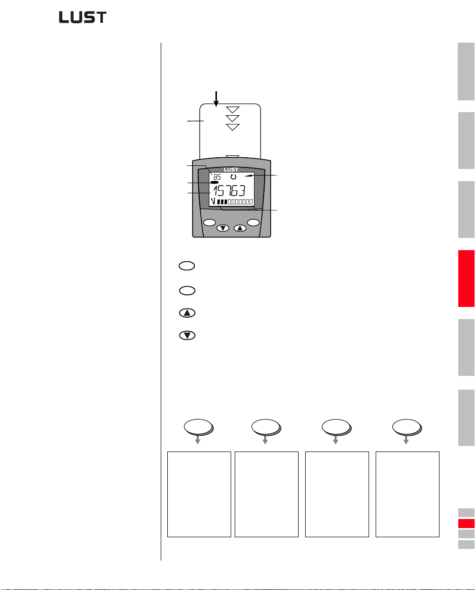
4 Commissioning
4.7 Operation with
K
EYPAD KP200
Overview of KEYPAD KP200
The KEYPAD can be plugged directly into the inverter module ( X4).
SMARTCARD chipcard to save and
(1)
transfer settings
(1)
3-digiti display, e.g. for parameter
(2)
number
(3) Current menu
SMART
(2)
(3)
(4)
C A R D
VAL
Hz
stop
return
Call up menu branches or parameters; Save changes;
start
enter
Start in “Control drive” mode
stop
Quit menu branches; Cancel changes; Stop in “Control drive” mode
return
(5)
(6)
start
enter
5-digit display for parameter name and
(4)
value
(5) Acceleration or braking ramp active
(6) Bar graph display, 10-character
Select menu, subject area or parameter; Increase setting
Select menu, subject area or parameter; Reduce setting
1
2
3
4
Table 4.3 Operating and dis play elements of the KEYPAD KP200
Menu structure The KEYPAD KP200 has a user-friendly menu structure whic h is identical
to that of the KP100 for the S
ASTERCONTROL SERVOCONTROLLERS.
M
VAL
Actuals
•select
•display
PARA
Subject area
• select
Parameter
• select
Capacity indicator
• change
MARTDRIVE VF1000 inverters and the
CTRL
Drive
• control
CARD
SMARTCARD
•read
•write
•Write
protection
Initial
commissioning
Figure 4.5 Functions of the menus
CDA3000 Operation Manual
4-15
5
A
DE
EN
FR
IT
ES
FR
Page 48
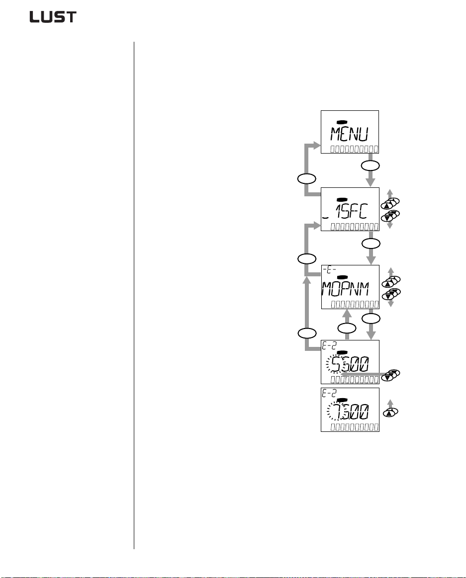
4 Commissioning
Example of parameter setting
(PARA menu)
• The parameters in the PARA menu are grouped into subject areas
according to their functions , in order to provide a clearer overview.
• Only the parameters to which the curren t us er level permits access
can be changed.
1. Select PARA menu.
2. Select desired subject area with
cursor keys and confirm with
stop
return
PARA
PARA
start
enter
start/enter.
start
enter
stop
return
3. Select desired parameter with
PARA
cursor keys (user level
1-MODE = 2).
start
enter
start
stop
return
enter
4. The current value is displayed,
with the last character flashing.
PARA
Switch to the next character
using the down key. Use the up
key to change the flashing
character. The fifth character at
the extreme left indicates the
PARA
0...9
preceding sign: (–) = minus.
The last character can be
entered as an exponent.
Save new value with start/enter
or cancel (without saving) with
stop/return.
CDA3000 Operation Manual
4-16
Page 49
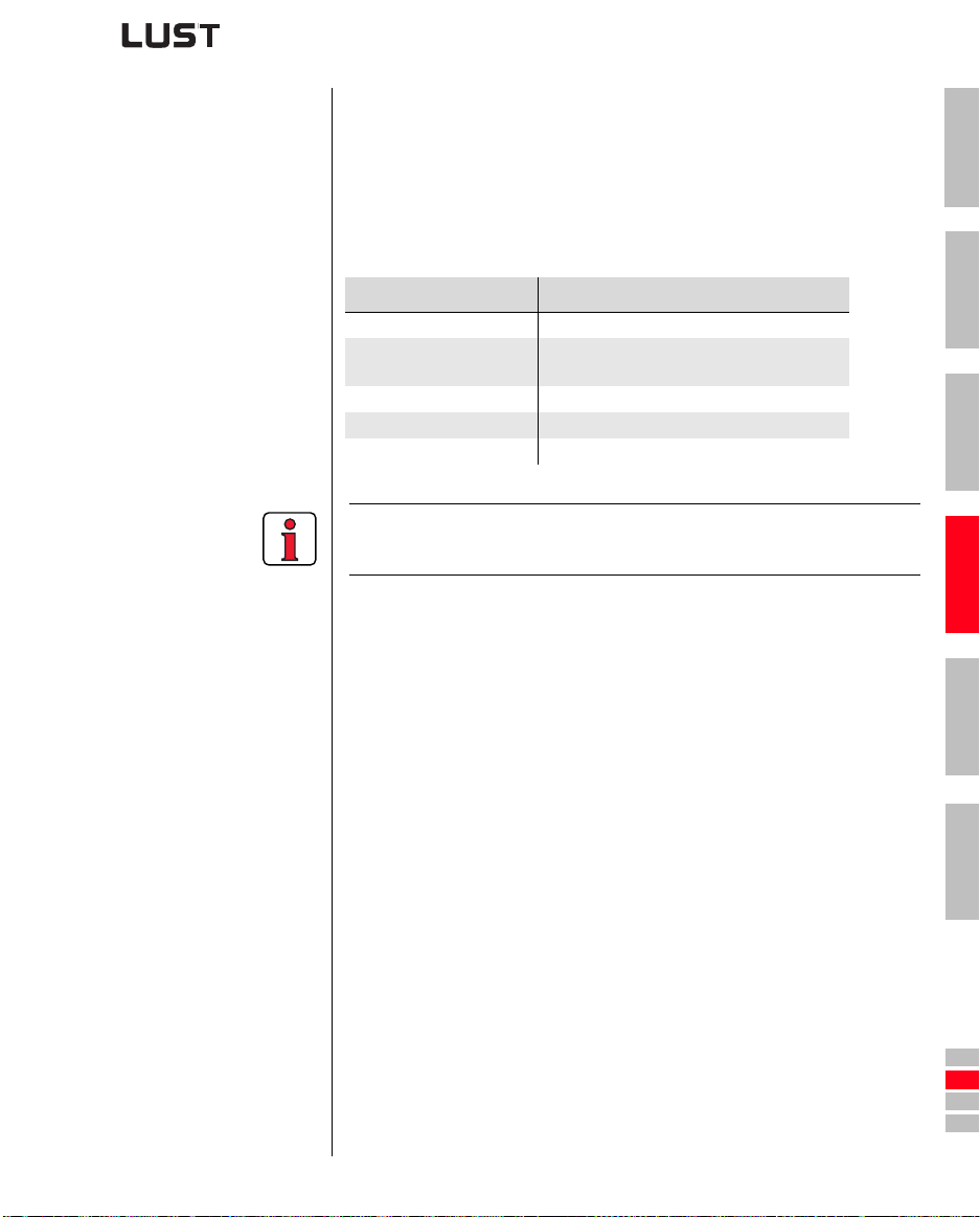
4 Commissioning
CARD MENU Read from/write to SMARTCARD:
• In this menu inverter settings can be saved to the SMARTCARD and
transferred to other inver ter modules.
• In every storage operation all param eters are always saved to the
MARTCARD. For read operations, either all parameters or only
S
parameters from one subject area (per read operation) can be
read-in.
Function Meaning
READ > ALL Read all parameters from SMARTCARD
READ > _27RS
WRITE Store all parameters on the SMARTCARD
LOCK Write-protect the SMARTCARD
UNLOCK Cancel the write protection
For more information on operation with t he KEYPAD refer to the KEYPAD
KP200 Operation Manual.
Parameters from subject area,
e.g. B. _27RS (reference structure)
1
2
3
4
CDA3000 Operation Manual
4-17
5
A
DE
EN
FR
IT
ES
FR
Page 50
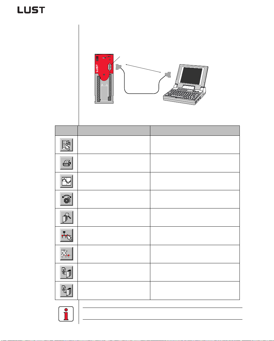
4 Commissioning
4.8 Operation with
D
RIVEMANAGER
The key functions
Icon Function Menu
Precondition :
•DRIVEMANAGER user software version V3.0 or higher installed on the
PC.
H1 H2 H3
X4
3 m max.
RS232
X4
!
ACHTUNG
Kondensatorentladezeit >3 Min.
Betriebsanleitung
beachten!
WARNING
capacitor disscharge
time >3 minutes.
Pay attention to the
operation manual!
X2
ATTENTION
temps de decharge
du condensteur
>3 min. observer le
mode dèmploi!
X3
X1
CCD-SUB90X
RS232
D
RIVE
M
ANAGER
Figure 4.6 Inverter module connectio n to PC/DRIVEMANAGER
Change setting of active
device
Active device > Change settings
Print parameter data set Active device > Print settings
Digital scope
Control drive
Active device > Monitoring > Quickly
changing digital scope values
Active device > Open-loop control >
Basic operation modes
CDA3000 Operation Manual
Connect to device
Bus initialization,
change setting
Communication > Connect > Single
device
Communication> Bus configuratio n
Disconnect all devices Communication > Disconnect
Save data set of active device
to file
Data set transfer from file to
active device
Active device > Save device settings to
Active device > Load device sett ings
from
For more information refer to the DRIVEMANAGER Manual.
4-18
Page 51
4 Commissioning
4.9 Parameter list (selection)
Any parameters can be
inserted into this
subject area using the
RIVEMANAGER (V3.0 or
D
higher). The number is
limited to 14. *
In the factory setting
the parameters listed
here are inserted.
* For more information
refer to the D
ANUAL.
M
CDA3000 Operation Manual
RIVEMANAGER
Name Unit Function
Subject area User-defined_11UA
01-MODE - User level of KP200 2
150-SAVE - Save setting in device READY
152 -ASTER - Preset terminal assignment DRV_1
180 -FISA0 - Function selector of ISA00 off
181 -FISA1 - Function selector of ISA01 off
242 -FOS02 - Function selector of OSD02 off
270-FFIX1 Hz
301 -FMIN1 Hz CDS1: Minimum frequency 0
303 -FMAX1 Hz CDS1: Maximum frequency 50
330-MOPTC - Type of PTC evaluation off
590 -ACCR1 Hz/s CDS1: Acceleration ramp 20
592 -DECR1 Hz/s CDS1: Braking ramp 20
594 -STPR1 Hz/s CDS1: Stop ramp 20
95-ERR1 h Last error -
Subject area Initial commissioning _15FC
150-SAVE - Back-up device setup READY
152 -ASTER - Preset terminal assignment DRV_1
Subject area Fixed frequencies_27FF
270-FFIX1 Hz Fixed frequency 20
Subject area Frequency limits_30OL
301 -FMIN1 Hz CDS1: Minimum frequency 0
303 -FMAX1 Hz CDS1: Maximum frequency 50
Subject area Motor protection _33MO
330-MOPTC - Type of motor PTC evaluation OFF
Subject area Driving profile generator _59DP
590 -ACCR1 Hz/s CDS1: Acceleration ramp 20
592 -DECR1 Hz/s CDS1: Deceleration ramp 20
594 -STPR1 Hz/s CDS1: Stop ramp 20
Subject area Encoder evaluation _79EN
790-ECLNC
Fixed frequency characteristic data
set CDS1
Pulses
Lines per revolution of encoder 1024
per rev
Factory
setting
20
4-19
Your
setting
1
2
3
4
5
A
DE
EN
FR
IT
ES
FR
Page 52
4 Commissioning
Name Unit Function
Factory
setting
Subject area Analog inputs _18IA
Settings3) for analog input ISA00:
OFF = Not active
180 -FISA0
0-10V = Voltage input 0...10 V
PM10V = Voltage input -10 V...+10 V
OFF
0-20 = Current input 0...20 mA
4-20 = Current input 4...20 mA
Subject area Driving sets_60TB
601-FFTB1 Hz Table frequency 2 10
602-FFTB2 Hz Table frequency 3 15
603-FFTB3 Hz Table frequency 4 20
1) Setting dependent on device. 2) Setting dependent on motor. 3) Selection, not complete
Your
setting
CDA3000 Operation Manual
4-20
Page 53
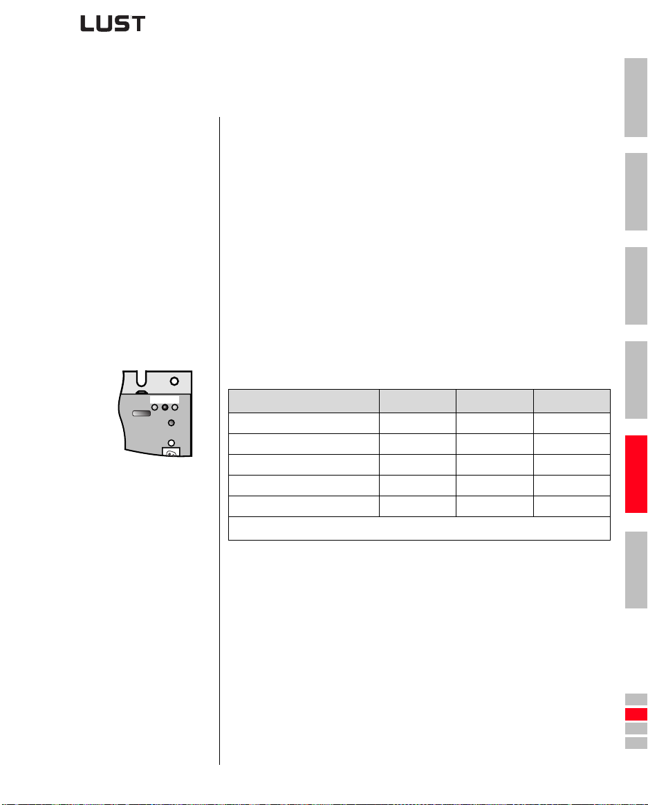
5 Diagnosis/Fault rectification
1
5.1 LEDs ........................................................................5-1
5.2 Error messages .......................................................5-2
5.3 User errors in KEYPAD operation .............................5-3
5.4 User errors in SMARTCARD operation .......................5-3
5.5 Errors in power switching ......................................5-3
5.6 Reset ........................................................................5-4
5.1 LEDs At the top right of the inverter module there are three status LEDs colored
red (H1), yellow (H2) and green (H3).
H1 H2 H3
Power on - -
Ready (ENPO set)
In service/Auto-tuning active
Warning
Error
❍ LED off, ● LED on, ✳ LED flashing
Device status Red LED (H1) Yellow LED (H2) Green LED (H3)
●
❍ ● ●
❍ ✳ ●
● ● / ✳ ●
✳ (flash code) ❍ ●
2
3
4
5
A
CDA3000 Operation Manual
5-1
DE
EN
FR
IT
ES
FR
Page 54
5 Diagnosis/Fault rectification
5.2 Error messages If a fault occurs in operation it is indicated by a flash code from LE D H1
(red) on the inverter module. The code indicat es the type of error. If a
KP200 is connected the KP200 indicates the error type as an
abbreviation.
Flash code of
red LED H1
1x E-CPU Collective error
2x E-OFF Undervoltage shut-off Check power supply. Also occurs briefly in response to normal power-off.
3x E-OC
4x E-OV
5x E-OLM
6x E-OLI
7x E-OTM
8x E-OTI Inverter overheating
1) For more information refer to CDA3000 Application Manual
Display
EYPAD
K
Explanation Cause/Remedy
Power-off, remove all control signals, power-on. If error recurs, inform LUST
1)
Service.
Current
overloadshut-off
Voltage overload
shut-off
Motor
protectionshut-off
Device safety
shut-off
Motor temperature
too high
Short-circuit, ground fault: Check cabling of connections, check motor
coil, check neutral conductor and grounding (see also section 3, Installation).
Device setup not correct: Check parameters of control loops. Check ramp
setting.
Voltage overload from mains: Check mains voltage. Restart device.
Voltage overload resulting from feedback from motor
operation): Slow down braking ramps. If not possible, use a braking resistor.
Motor overloaded (after I x t monitoring): Slow down process cycle rate if
possible. Check motor dimensioning.
Device overloaded: Check dimensioning. Possibly use a larger device.
Motor PTC correctly connected?
Parameter MOPTC correctly set(type of motor PTC evaluation)?
Motor overloaded? Allow motor to cool down. Check dimensioning.
Ambient temperature too high: Improve ventilation in switch cabinet.
Load too high during driving/braking: Check dimensioning. Possibly use a
braking resistor.
(regenerative
Table 5.1 Error messages
Helpline If you need further assistance, our specialists at the LUST helpline will be
glad to help.
You can reach us:
Mon.-Thur.: 8 a.m. - 4. 30 p.m.Tel. ++49 64 41/9 66-180
Fri.: 8 a.m. - 4 p.m. Tel. ++49 64 41/9 66 -180
E-mail: [email protected]
Fax: ++49 64 41/9 66-177
CDA3000 Operation Manual
5-2
Page 55
5 Diagnosis/Fault rectification
5.3 User errors in
K
EYPAD
operation
5.4 User errors in
MARTCARD
S
operation
Error Cause Remedy
ATT1 Parameter cannot be changed at current
user level or is not editable.
ATT2 Motor must not be controlled via the CTRL
menu.
ATT3 Motor must not be controlled via the CTRL
menu because of error state.
ATT4 New parameter value impermissible Change value.
ATT5 New parameter value too high Reduce value.
ATT6 New parameter value too low Increase value.
ATT7 Card must not be read in current state. Reset start signal.
ERROR Invalid password Enter correct password.
Table 5.2 KEYPAD user error: Reset with Start/Enter
Error Meaning Remedy
ERR91 SMARTCARD write-protected
ERR92 Error in plausibility check
ERR93 SMARTCARD not readable, wrong inverter type
ERR94 SMARTCARD not readable, parameter not compatible
ERR96 Connection to SMARTCARD broken
ERR97 SMARTCARD DATA invalid (checksum)
ERR98 Insufficient memory on SMARTCARD
ERR99 Selected area not present on SMARTCARD, no parameters
transferred to S
Table 5.3 SMARTCARDerror: Reset with Stop/Return
MARTCARD
Select user level 1-MODE higher.
Cancel start signal from a
different control location.
Reset error.
Use different
MARTCARD
S
1
2
3
4
5
A
5.5 Errors in power switching
CDA3000 Operation Manual
Error Cause Remedy
Power on. Inverter module
shows no response (LEDs
off).
If switching is too frequent,
the device protects itself by
means of high-resistance
isolation from the system.
5-3
After a rest phase of a few
minutes the device is ready
to start once again.
DE
EN
FR
IT
ES
FR
Page 56
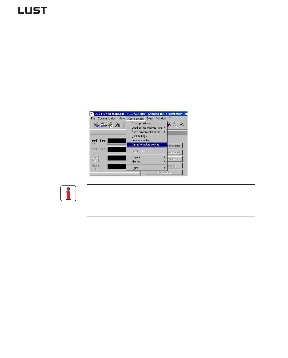
5 Diagnosis/Fault rectification
5.6 Reset The reset function is divided into two areas with differing effects.
Parameter reset restor es to the last value stored in the device. Device
reset restores the entire data set to factory setting (delivery defaults).
Parameter reset with KEYPAD If you are in the setup mode of a parameter and press the two cursor keys
simultaneously, the parameter you are currently editing will be reset to the
last setting stored (= saved with parameter 150-SAVE).
Factory setting with KEYPAD Press both curso r keys simultaneously during inverter module powe r-up
to reset all parameters to their factory defaults and the system is
reinitialized.
Factory setting with
RIVEMANAGER
D
In the “Active device” menu, the “Res et to factory setting” option can be
used to restore the delivery defaults of the device.
CDA3000 Operation Manual
Note: The factory setting causes application data set 1 (traction and
lifting drive, DRV_1) to be loaded. Check the term inal
assignment and functionality of the inverter module in this
operation mode, or load your own user data set.
5-4
Page 57
Appendix A
A.1 Current capacity of inverter modules .................... A-2
A.2 Technical data ........................................................ A-5
A.3 Ambient conditions ................................................ A-8
A.4 Project planning notes, Cold plate ........................ A-9
A.5 Project planning notes for multi-motor
operation .............................................................. A-10
A.5.1 Engineering note „motor contactor“.................... A-11
A.6 through use of a line choke ................................. A-12
A.7 UL approbation ..................................................... A-14
A.8 Layouts of all sizes .............................................. A-15
1
2
3
4
5
CDA3000 Operation Manual
A-1
A
DE
EN
FR
IT
ES
FR
Page 58
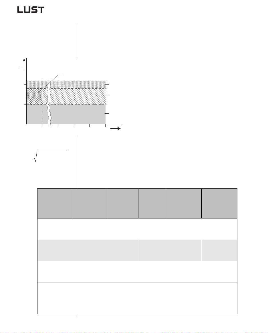
A.1 Current capacity
of inverter
modules
I
I
N
2
1
*Intermittent I
I
eff
1
--
T
(3)
525404550
> I
N
eff
n
2
Σ
I
⋅⋅=
i1=
t
i
i
The maximum permissible inverte r output current and the peak current
are dependent on the ma ins voltage, the moto r cable length, the p ower
stage switching frequency an d the ambient tem perat ure. I f th e c onditions
change, the maximum permissible current capacity of the inverter
modules also changes. Refer to the following graphs and tables.
(1) Continuous
(2) Intermittent* > 5 Hz rotating field frequency
Inverter modules 0.37 to 15 kW
I/IN = 1.8 (for 30 s at 4 kHz)
I/IN = 1.8 (for 30 s at 8 kHz)
(4)
(2)
(1)
f [Hz]
I/IN = 1.8 (for 30 s at 16 kHz)
Inverter modules 22 to 90 kW
I/IN = 1.5 (for 60 s at 4 kHz)
I/IN = 1.5 (for 60 s at 8 kHz)
(3) Intermittent* 0 to 5 Hz rotating field frequency
Inverter modules 0.37 to 15 kW
I/IN = 1.8 (for 30 s at 4 kHz)
I/IN = 1.25-1.8 (for 30 s at 8 kHz)
Inverter modules 22 to 90 kW
I/IN = 1.5 (for 60 s at 4 kHz)
I/IN = 1-1.5 (for 60 s at 8 kHz)
(4) Pulse mode
Inverter modules 0.37 to 15 kW
I/IN = approx. 2.2 (at 4, 8, 16 kHz)
Inverter modules 22 to 90 kW
I/IN = approx. 1.8 (a t 4, 8 kHz)
Inverter modules for 230 V systems
Inverter module
CDA32.004,Cx.x
CDA32.006,Cx.x
CDA32.008,Cx.x
Peak current for 30 s with inverter module 0.75 to 15 kW
Peak current for 60 s with inverter module 22 to 90 kW
Cooling air temperature: 45 °C at power stage switching frequency 4 kHz
1) With heat sink HS3... or additional cooling surface
CDA3000 Operation Manual
Rec. 4-pole
standard motor
[kW]
Switching
frequency of
power stage
[kHz]
4
1)
0.75
8
16
4
1)
1.1
8
16
4
1)
1.5
8
16
4 0 ° C a t p o w e r s t a g e s w i t c h i n g f r e q u e n c y 8 , 1 6 k H z
Rated
current [A]
4
4
3
5.5
5.5
4.3
7.1
7.1
5.5
A-2
Peak current for
intermittent
mode
0 to 5 Hz [A]
7.2
7.2
5.4
9.9
9.9
7.7
12.8
12.8
8
Mains voltage 1 x 230 V -20 % +15 %
Motor cable length 10 m
Mounting height 1000 m above MSL
End-to-end mounting
Peak current for
intermittent
mode
> 5 Hz [A]
7.2
7.2
5.4
9.9
9.9
7.7
12.8
12.8
9.9
Page 59
Inverter modules for 400/460 V systems:
Rec. 4-pole
Inverter module
CDA34.003,Cx.x 0.75
CDA34.005,Cx.x
CDA34.006,Cx.x
CDA34.008,Wx.x 3.0
CDA34.010,Wx.x 4.0
CDA34.014,Wx.x 5.5
CDA34.017,Wx.x 7.5
standard motor
[kW]
1)
1)
1.5
2.2
Switching
frequency of
power stage
[kHz]
4
8
16
4
8
16
4
8
16
4
8
16
4
8
16
4
8
16
4
8
16
Rated
current I
at 400V
2.2
2.2
1.0
4.1
4.1
2.4
5.7
5.7
2.6
7.8
7.8
5
10
10
6.2
14
14
6.6
17
17
8
N
[A]
2)
Rated
current
[A]
I
N
at 460V
2.2
2.2
1.0
4.1
3.6
-
5.7
5.7
-
7.8
7.8
-
10
8.8
-
14
12.2
-
17
13.5
-
Peak current for
intermittent
3)
0 to 5 Hz [A]
mode
4
4
1.1
7.4
7.4
4.3
10.3
10.3
4.7
14
14
7.8
18
16.5
7.8
25
21
9.2
31
21.2
9.2
Peak current for
intermittent
mode
> 5 Hz [A]
4
4
1.8
7.4
7.4
4.3
10.3
10.3
4.7
14
14
9
18
18
11
25
21
11.9
31
31
14.4
1
2
3
4
5
CDA34.024,Wx.x 11
CDA34.032,Wx.x 15
CDA34.045,Wx.x 22
CDA34.060,Wx.x 30
CDA3000 Operation Manual
16
16
4
8
24
24
15
24
24
43
-
40
22
43
43
27
A
4
8
4
8
4
8
32
32
20
45
45
60
60
32
28
45
39
60
52
-
A-3
58
40
22
68
54
90
71
58
58
36
68
68
90
90
DE
EN
FR
IT
ES
FR
Page 60
N
[A]
2)
Rated
current
[A]
I
N
at 460V
72
62
90
78
110
96
143
124
170
147
Peak current for
intermittent
mode
3)
0 to 5 Hz [A]
112
78
135
104
165
110
215
143
255
212
Peak current for
intermittent
mode
> 5 Hz [A]
112
112
135
135
165
165
215
215
255
255
Rec. 4-pole
Inverter module
standard motor
[kW]
CDA34.072,Wx.x 37
CDA34.090,Wx.x 45
CDA34.110,Wx.x 55
CDA34.143,Wx.x 75
CDA34.170,Wx.x 90
Switching
frequency of
power stage
[kHz]
4
8
4
8
4
8
4
8
4
8
Rated
current I
at 400V
72
72
90
90
110
110
143
143
170
170
CDA34.250,Wx.x 132 4 250 250 255 300
Peak current for 30 s with inverter module 0.75 to 15 kW
Peak current for 60 s with inverter module 22 to 132 kW
Cooling air temperature: 45 °C at power stage switching frequency 4 kHz
(CDA34.003 - 34.032) 40 °C at power stage switching frequency 8, 16 kHz
Cooling air temperature:40 °C at power stage switching frequency 4 kHz
(CDA34.045 - 34.250)
1) With heat sink HS3... or additional cooling surface
2) Mains voltage 3 x 400 V ±10 %
3) Mains voltage 3 x 460 V ±10 %
Motor cable length 10 m
Mounting height 1000 m above MSL
End-to-end mounting
CDA3000 Operation Manual
A-4
Page 61
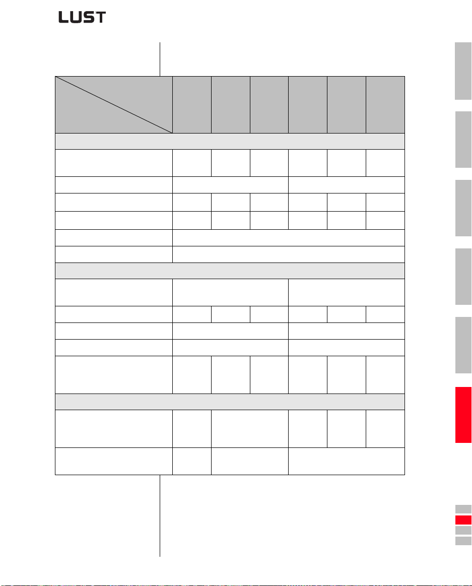
A.2 Technical data
Designation
Technical data
Output, motor side
Recommended rated power
with 4-pole Standard motor
Voltage 3 x 0 ... 230 V 3 x 0 ... 400/460 V
Continuous current (RMS) (IN)
Peak current 1.8 x IN for 30 s
Rotating field frequency 0 ... 400 Hz
Switching frequency of power stage 4, 8, 16 kHz
Input, mains side
Mains voltage
Device connected load 1.7 kVA 2.3 kVA 3.0 kVA 1.6 kVA 3.0 kVA 4.2 kVA
Asymmetry of mains voltage - ±3 % max.
Frequency 50/60 Hz ±10 % 50/60 Hz ±10 %
Power loss at 4 kHz
Power stage clock
frequency 8/16 kHz
Braking chopper power electronics
Peak braking power with int.
braking resistor (only with version
CDA34 ..., Wx.x, BR)
Minimum ohmic resistance of an
externally installed braking resistor
CDA32.004 to CDA34.006
CDA32.004
0.75 kW 1.1 kW 1.5 kW 0.75 kW 1.5 kW 2.2 kW
4.0 A 5.5 A 7.1 A 2.2 A 4.1 A 5.7 A
7.2 A 9.9 A 12.8 A 4.0 A 7.4 A 10.3 A
48 W
55 W
- - – –
100 Ω 56 Ω 180 Ω
CDA32.006
1 x 230 V
-20 % +15 %
75 W
82 W
95 W
105 W
CDA32.008
CDA34.003
55 W
70 W
CDA34.005
3 x 460 V
-25 % +10 %
80 W
112 W
106 W
148 W
1.6 kW
at 360
CDA34.006
1
2
3
4
5
Ω
A
CDA3000 Operation Manual
A-5
DE
EN
FR
IT
ES
FR
Page 62
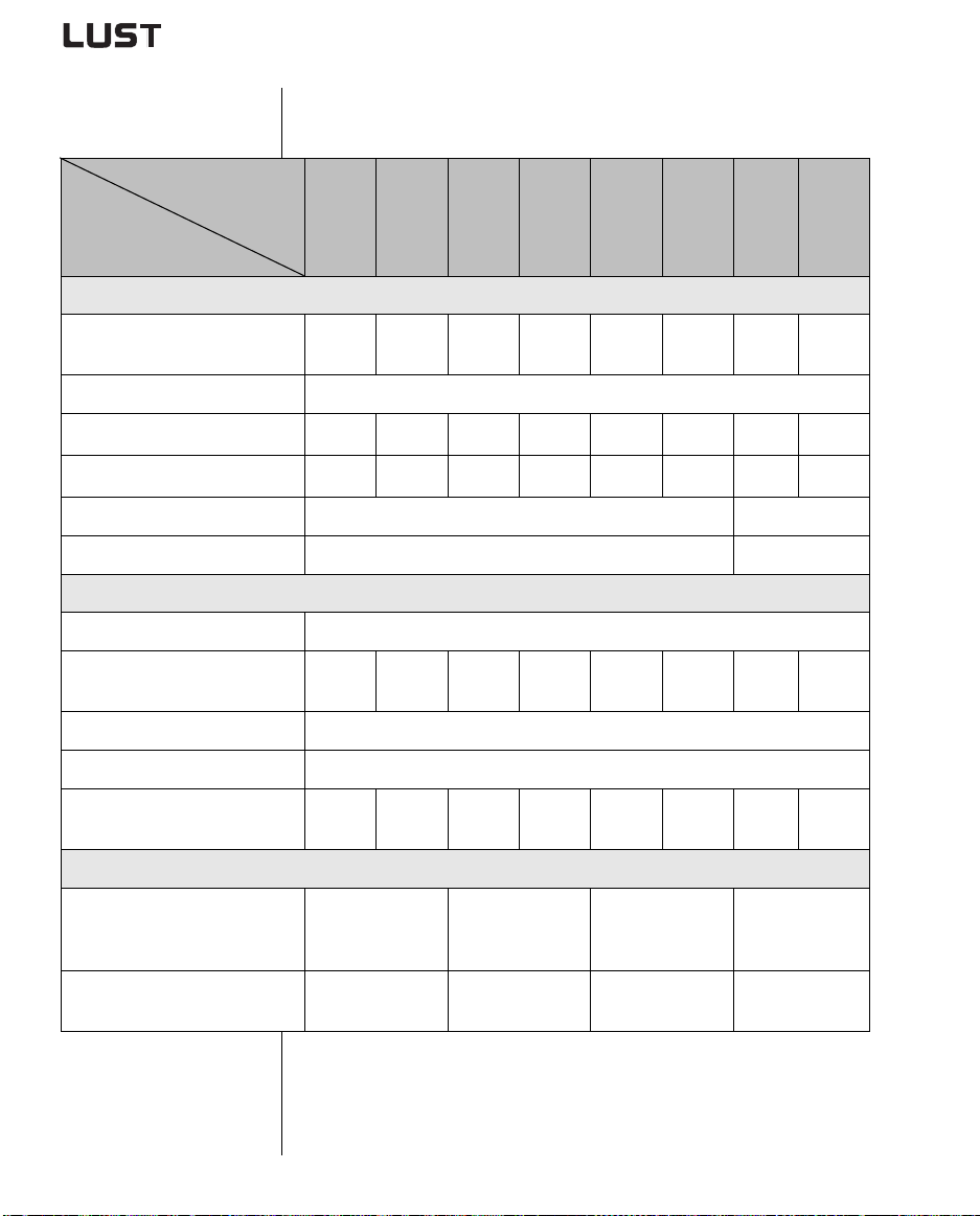
Designation
CDA34.008 to CDA34.060
Technical data
Output, motor side
Recommended rated power
with 4-pole Standard motor
Voltage 3 x 0 ... 400/460 V
Continuous current (RMS) (IN)
Peak current 1.8 x IN for 30 s
Rotating field frequency 0 ... 400 Hz 0 ... 200 Hz
Switching frequency of power stage 4, 8, 16 kHz 4, 8 kHz
Input, mains side
Mains voltage 3 x 460 V -25 % +10 %
Device connected load 5.7 kVA 7.3 kVA 10.2 kVA 12.4 kVA 17.5 kVA 23,3 kVA
Asymmetry ±3 % max.
Frequency 50/60 Hz ±10 %
Power loss at Power stage4 kHz
clock frequency 8/16 kHz
CDA34.008
3.0 kW 4.0 kW 5.5 kW 7.5 kW 11 kW 15 kW 22 kW 30 kW
7.8 A 10 A 14 A 17 A 24 A 32 A 45 A 60 A
14 A 18 A 25 A 31 A 43 A 58 A 68 A 90 A
135 W
162 W
CDA34.010
172 W
207 W
CDA34.014
210 W
268 W
CDA34.017
255 W
325 W
CDA34.024
315 W
400 W
CDA34.032
400 W
510 W
CDA34.045
32.8
kVA
777 W
933 W
43.8 kVA
1010 W
1220 W
CDA34.060
Braking chopper power electronics
Peak braking power with int.
braking resistor (only with version
CDA34 ..., Wx.x, BR)
Minimum ohmic resistance of an
externally installed braking resistor
CDA3000 Operation Manual
6.0 kW
at 90
Ω
81 Ω 47 Ω 22 Ω 18 Ω
6.0 kW
at 90
6.0 kW
Ω
at 90
Ω
A-6
-
Page 63
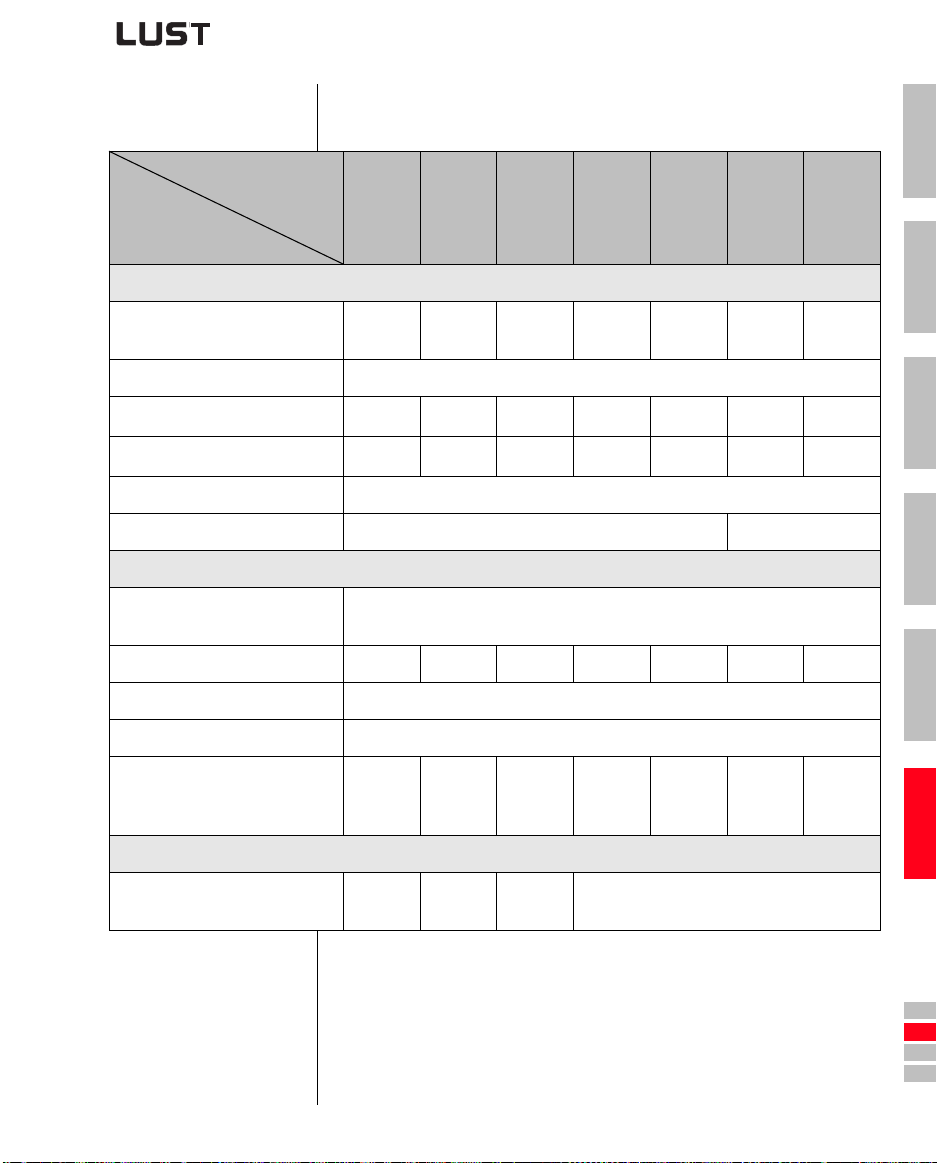
CDA34.072 to CDA34.250
Designation
Technical data
Output, motor side
Recommended rated power
with 4-pole Standard motor
Voltage 3 x 0 ... 400/460 V
Continuous current (RMS) (IN)
Peak current 1.5 x IN for 60 s
Rotating field frequency 0 ... 200 Hz
Switching frequency of power stage 4, 8 kHz 4 kHz
Input, mains side
Mains voltage
Device connected load 52.5 kVA 65.6 kVA 80 kVA 104 kVA 124 kVA 145 kVA 173 kVA
Asymmetry of mains voltage ±3 % max.
Frequency 50/60 Hz ±10 %
CDA34.072
37 kW 45 kW 55 kW 75 kW 90 kW 110 kW 132 kW
72 A 90 A 110 A 143 A 170 A 210 A 250 A
108 A 135 A 165 A 214 A 255 A 300 A 300 A
CDA34.090
CDA34.110
-25 % +10 %
CDA34.143
3 x 460 V
CDA34.170
CDA34.250
CDA34.250
1
2
3
4
5
Power loss at 4 kHz
Power stage clock
frequency 8 kHz
Braking chopper power electronics
Minimum ohmic resistance of an
externally installed braking resistor
CDA3000 Operation Manual
1270 W
1530 W
13 Ω 12 Ω 10 Ω 5.6 Ω
1510 W
1820 W
1880 W
2290 W
2450 W
2970 W
A-7
2930 W
3550 W
3405 W-4043 W
-
A
DE
EN
FR
IT
ES
FR
Page 64
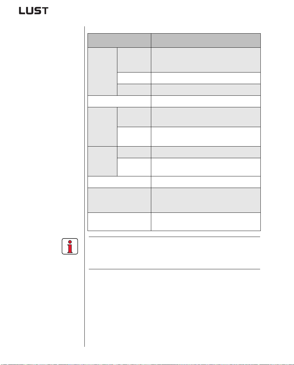
A.3 Ambient
conditions
Characteristic Inverter module
-10 ...45 ° C (BG1 ... BG5)
Temperature
range
in operation
in storage -25 ... +55 °C
0 ... 40 ° C (BG6 ... BG8)
with power reduction to 55 ° C
in transit -25 ... +70 °C
Relative air humidity 15 ... 85 %, condensation not permitted
Vibration: 0.075 mm in frequency range 10 ... 58 Hz
2
Shock: 9.8 m/s
in frequency range >58 ... 500 Hz
Mechanical
in stationary
use
strength to
IEC 68-2-6
in transit
Vibration: 3.5 mm in frequency range 5 ... 9 Hz
2
Shock: 9.8 m/s
in frequency range >9 ... 500 Hz
Device IP20 (NEMA 1)
Protection
Cooling
method
Cold plate: IP20
Push-through heat sink: IP54 (3 ...15 kW)
Touch protection VBG 4
up to 1000 m above MSL, above 1000 m above MSL
Mounting height
with power reduction 1% per 100 m, max. 2000 m
above MSL
CDA3000 Operation Manual
Voltage stress of the
motor winding
typical slew rate 3 - 6 kV/µs
Note: If a rotating field frequency of > 200/400 Hz is required,
inverter modules with special firmware for high-frequency
motors must be ordered. Detailed order data see in order
calogue CDA3000.
A-8
Page 65
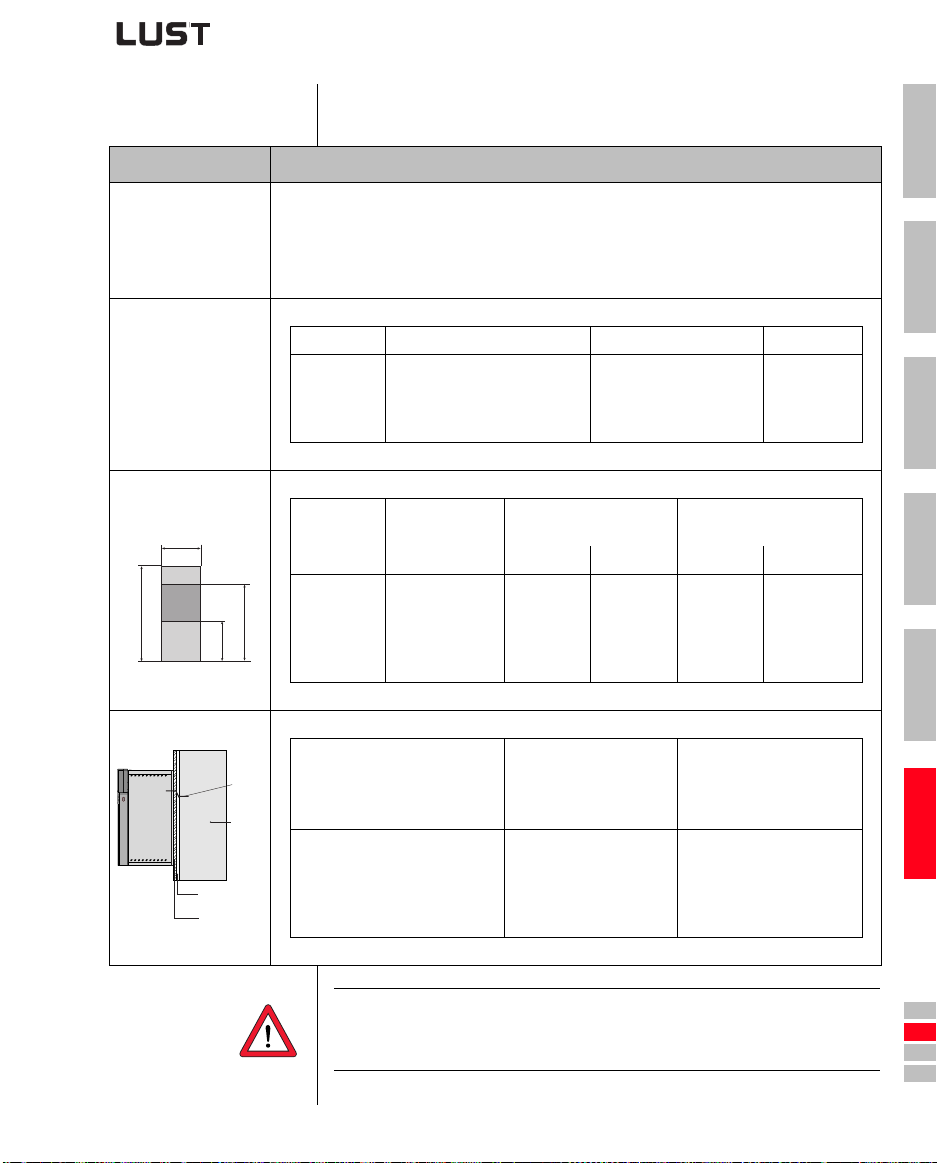
A.4 Project planning
notes, Cold plate
Subject Project planning notes
• Evenness of contact surface = 0.05 mm
Thermal connection to
cooler
Distribution of
power loss
Active cooling surface
B
H
Thermal resistance
a
R
Cooler
Heat transfer
compound
CDA3000
backing plate
b
th
Roughness of contact surface = roughness factor 6.3
• Coat area between inverter module (“cold plate” backing plate) and cooler with heat transfer
compound (coat thickness 30-70µ).
• The temperature in the middle of the inverter module backing plate must not exceed 85 °C.
Size Power Heat sink Housing
BG 1/2
BG 3
BG 4
BG 5
Size
BG 1
BG 2
BG 3
BG 4
BG 5
BG 1
BG 2
BG 3
BG 4
BG 5
0.37 to 2.2 kW
5.5 to 7.5 kW
11 to 15 kW
Power
[kW]
0.37 to 0.75 kW
1.1 to 2.2 kW
3 to 4 kW
5.5 to 7.5 kW
11 to 15 kW
Size
3 to 4 kW
Device basic area
B H a b
70
70
100
150
200
0.37 to 0.75 kW
[mm]
Power
[kW]
1.1 to 2.2 kW
3 to 4 kW
5.5 to 7.5 kW
11 to 15 kW
approx. 65%
approx. 70%
approx. 75%
approx. 80%
193
218
303
303
303
approx. 35%
approx. 30%
approx. 25%
approx. 20%
Active cooling surface
[mm]
50
90
120
65
80
Thermal resistance between
active cooling surface and
cooler
R
th
0.015
165
200
260
215
300
[K/W]
0.05
0.05
0.03
0.02
1
2
3
4
5
A
CDA3000 Operation Manual
Note: For size 3 (BG3) and above an active cooling surface or
cooler is required. The usual mounting surfa ce or a position
on the machine housing is not adequate.
A-9
DE
EN
FR
IT
ES
FR
Page 66
A.5 Project planning
notes for multimotor operation
Subject Project planning notes
Current
configuration of
inverter module
Motor control
method
Motor choke A motor output choke must always be used. The motor choke limits the
Motor cable length The total length of the overall motor cable is produced by adding the
Motor protection In multi-motor operation the parallel-connected motors cannot be
All motors have
the same power
output
The motors have
different power
outputs
The sum total of the motor currents must be less than the rated output
current of the inverter module
Σ of motor currents, (I
Multi-motor operation is only permitted with the VFC motor control
method.
du/dt and thus the leakage currents, and protects again switching
voltage overload resulting from switching of the motor inductance.
individual lengths per motor.
protected by the inverter module. As a result, depending on application
the motor protection should be provided by means of external motor
circuit-breakers or thermistor protective relays.
In this application the torque characteristics of all motors remain
roughly equal.
If the motor outputs are very different, problems may occur on startup
and at low speeds. This is because of the high stator resistance of small
motors and the resultant high voltage drop on the stator coil.
In practice: With a power ratio of around 1:4 between the motors, the
starting torque of the smallest motor is still approx. 70%
of the nominal torque. If the torque of approx. 70% is not
sufficient, a larger motor must be used.
+ IM2 + I
M1
Mn
) < I
inverter
CDA3000 Operation Manual
Speed
proportionality
Connecting
individual motors
If all the motors are started together, the small motor will
start up later, because the slip frequency is higher.
Differing motor output speeds can only be attained by using motors
with differing nominal speeds, e.g. 1440 rpm and 2880 rpm. The speed
ratio of approx. 1:2 is maintained during the speed change. The
accuracy depends on the slip and thus on the load.
When connecting motors, ensure that the connection current is not
higher than the inverter peak current. It is advantageous if the inverter
load is >40%.
This 40% base load backs up the output voltage of the inverter module
at the moment of connection of the motor.
During connection the motor must not be run in the field
weakening range, since the connected motor would
otherwise have to run at reduced runup torque.
A-10
Page 67
A.5.1 Engineering note
„Motor
contactor“
In order to prevent an unexpected starting it is necessary to avoid a
dangerous motion at acc ess to the m achine according to EN1037 - t hus
to provide galvanic separation with a motor contactor in the cable
between inverter and motor.
Basically the switching in the motor cable must always be made in
deenergized condition, otherwise th ere will be problems of burnt contacts
and a switching off due to overvoltage or overcurrent.
To guarantee a deenergized switching, it is necessary that the contacts of
the motor contactor are closed before enabling the power stage of th e
inverter. In the opposite case it is necessary that the c ontacts are c losed
until the power stage is switched-off.
This will be reached by planning corresponding safety time for the
switching of the motor c ontactor dur ing control sequenc e or by using the
special software function of CDA3000 inverter.
Software function „Switching of motor contactor“:
Step Action
Adjust one of the digital outputs of
1
the inverter to function „ENMO“.
Adjust the necessary delay time at
2
parameter 247_TENMO.
Example for the digital output OSD01
(terminal plug X2-16/17)
• choose in subject area _240D parameter 241_FOS01
• adjust parameter 241_FOS01 to
„ENMO“
• memorize the adjustment
• choose parameter 247_TENMO in
subject area _240D
• choose parameter 247_TENMO applied to your application (factory setting = 300 ms)
• value area = 0 ... 2000 ms
1
2
3
4
5
CDA3000 Operation Manual
A-11
A
DE
EN
FR
IT
ES
FR
Page 68
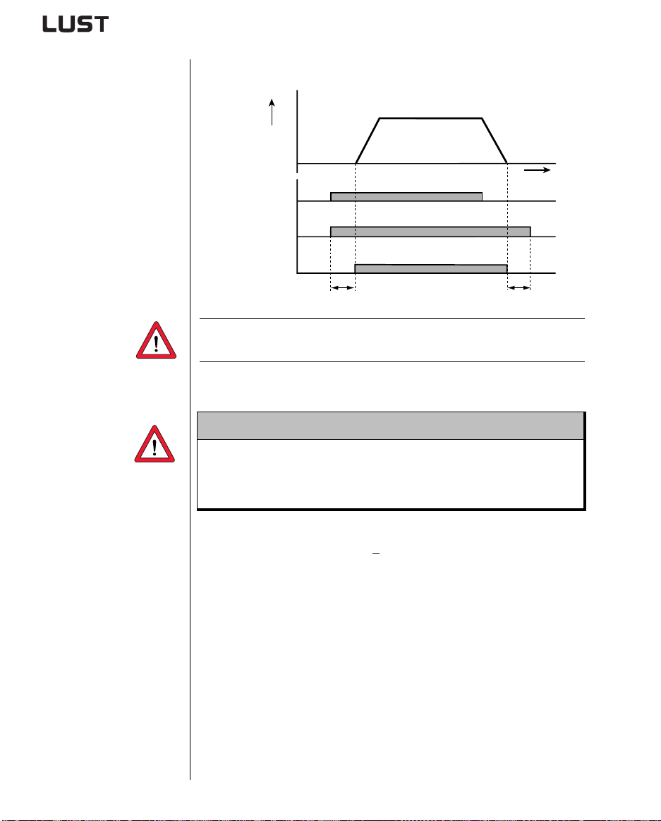
Example for the digital output OSD01:
f [Hz]
A.6 through use of a
line choke
STR (Start/Stop)
e.g. OSD01 (ENMO)
power stage
0
1
0
1
0
1
0
TENMO
t
TENMO
Attention: A corresponding driver relay has to be used be tween the
digital output and the motor c ontactor.
Line chokes are required:
• Where the drive controller is used in applications with disturbance
variables corresponding to environment class 3, as per
EN 61000-2-4 and above (hostile industrial environment).
• With a dc-link between multiple drive controllers.
Characteristics of environment class 3 include:
• Mains voltage fluctuations > + 10 % U
N
• Short-time interruptions between 10 ms and 60 s
• Voltage asymmetry > 3%
Environment class 3 typically applies wher e:
• a major part of the load is supplied by power converters (dc choppers
or soft-start equipment).
• welding machines are present.
• induction or arc furnaces are pre sent.
• large motors are started frequ ently.
• loads fluctuate rapidly.
CDA3000 Operation Manual
A-12
Page 69
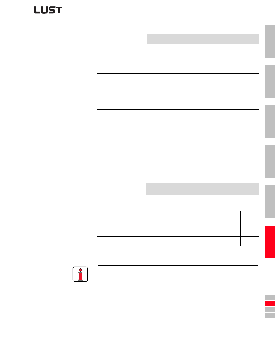
Mains load (example)
Without line choke With line choke Change
4 kW inverter,
mains impedance
0.6 mH
Voltage distortion (THD)
Mains current amplitude 18.9 A 9.7 A -48 %
Mains current effective 8.5 A 6.23 A -27 %
Commutation notches
referred to the mains
voltage
Life of the DC-link
capacitors
1) THD = Total Harmonic Distortion (U5 ...U41)
T able A.1 Change in system load resulting from insertion of a line choke
1)
with 4% short-circuit voltage based on the example of a 4 kW
inverter CDA34.010
99 % 33 % -67 %
28 V 8 V -70%
Nominal life
4 kW inverter,
mains impedance
6mH
2 to 3 times
nominal life
Without line choke
compared to
with line choke
+100 to 200 %
1
2
3
CDA3000 Operation Manual
Mains voltage asymmetry (example)
Without line choke With line choke
4 kW inverter, mains
impedance 0.6 mH
Asymmetry of mains
voltage
Mains current amplitude 18.9 A 25.4 A 25.1 A 9.7 A 10.7 A 11 A
Mains current effective 8.5 A 10.5 A 10.2 A 6.2 A 6.7 A 6.8 A
Table A.2 Effect of the line choke with asymmetrical mains voltage
based on the example of a 4 kW inverter CDA34.010
Recommended:
The example shows that the benefits of a line choke with 4 % short-circuit
voltage are multi-faceted. We therefore recommend that you use a line
choke as a matter of course.
0 % +3 % -3 % 0 % +3 % -3 %
A-13
4 kW inverter, mains
impedance 6 mH
4
5
A
DE
EN
FR
IT
ES
FR
Page 70
A.7 UL approbation
Tightening torque of
grounding lead terminals
as mains/motor terminals 0.5 ... 0.6 Nm CDA32.004 AWG 16 N/M 10 A
as mains/motor terminals 0.5 ... 0.6 Nm CDA32.006 AWG 14 N/AWG 16 M 10 A
as mains/motor terminals 0.5 ... 0.6 Nm CDA32.008 AWG 14 N/AWG 16 M 20 A
as mains/motor terminals 0.5 ... 0.6 Nm CDA34.003 AWG 16 N/M 10 A
as mains/motor terminals 0.5 ... 0.6 Nm CDA34.005 AWG 16 N/M 10 A
as mains/motor terminals 0.5 ... 0.6 Nm CDA34.006 AWG 16 N/M 10 A
as mains/motor terminals 0.5 ... 0.6 Nm CDA34.008 AWG 14 N/M 15 A
as mains/motor terminals 0.5 ... 0.6 Nm CDA34.010 AWG 14 N/M 15 A
as mains/motor terminals 0.5 ... 0.6 Nm CDA34.014 AWG 12 N/M 20 A
as mains/motor terminals 0.5 ... 0.6 Nm CDA34.017 AWG 12 N/M 25 A
as mains/motor terminals 1.2 ... 1.5 Nm CDA34.024 AWG 10 N/M 30 A
as mains/motor terminals 1.2 ... 1.5 Nm CDA34.032 AWG 8 N/M 50 A
as mains/motor terminals 6 ... 8 Nm CDA34.045 AWG 6 N/M 50 A
as mains/motor terminals 6 ... 8 Nm CDA34.060 AWG 6 N/M 63 A
as mains/motor terminals 6 ... 8 Nm CDA34.072 AWG 4 N/M 80 A
6 ... 8 Nm 15 ... 20 Nm CDA34.090 AWG 2 N/M 100 A
6 ... 8 Nm 15 ... 20 Nm CDA34.110 AWG 1 N/M 125 A
as mains/motor connection
Measures to maintain UL approbation
1. Swit ch cabinet mounting with IP54 protection and pollution degree 2
is mandatory.
2. The de vices are only usable in systems with sur ge st rength class III.
3. Only UL approved fuses and circuit-breakers may be used.
CDA32.xxx : Mains fuses mi n. 250 V H or K5
CDA34.xxx : Mains fuses mi n. 600 V H or K5
4. The devices are usable in systems with a maximum current capacity
of 5000 A.
5. The connecting cables (mains power, motor and control cables) must
be UL approved.
CDA32.xxx : Min. 300 V cables (mains/motor), Cu 75° C min.
CDA34.xxx : Min. 600 V cables (mains/motor), Cu 75° C min.
Tightening torque of
mains/motor terminals
10 Nm (connection via
screw bolt)
Table A.3 Cable cross-sections - mains (N), motor (M)
Device Wire cross-section Mains fuse
CDA34.143 AWG 2/0 N/M 160A
CDA3000 Operation Manual
A-14
Page 71
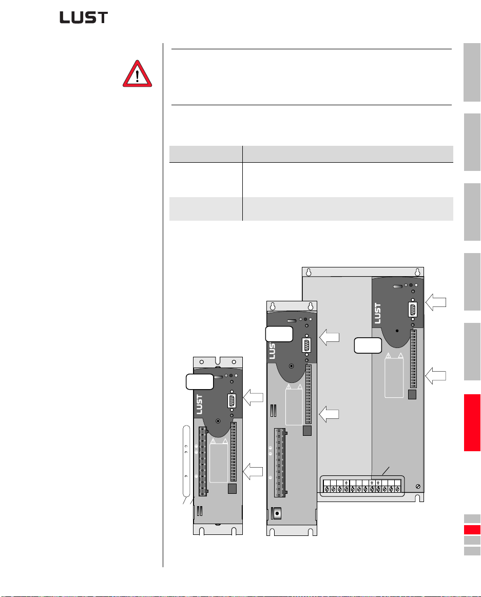
Attention: The inverter modules can typically be over lo aded with 1.5 x
for 60 s (1.8 x IN for 30 s). The effective inverter capacity
I
N
utilization (I
≤ IN) must never be greater than IN (rated
eff.
current).
Minimum cross-section of the grounding lead to DIN VDE 0100 Part 540
1
A.8 Layouts of all
sizes
Cross-section PE mains connection
Mains power cable
<10 mm²
Mains power cable
>10 mm²
Grounding lead (PE) cross section of at least 10 mm² or lay a
second electrical conductor parallel to the existing grounding
lead, because the operational leakage current is > 3.5 mA.
PE conductor with cross-section of mains power cable - see
VDE 0100 Part 540
Table A.4 Minimum cross-section of the grounding lead
H1 H2 H3
BG1+2
U
V
W
L+
RB
L-
N
L3
BG3+4
H1 H2 H3
ACHTUNG
Kondensatorentladezeit >3 Min.
X7
X4
U
V
W
!
ACHTUNG
Kondensatorentladezeit >3 Min.
Betriebsanleitung
beachten!
L+
WARNING
capacitor disscharge
time >3 minutes.
RB
Pay attention to the
operation manual!
L-
ATTENTION
temps de decharge
du condensteur
>3 min. observer le
mode dèmploi!
L1
L2
L3
X1
X6
X2
X3
Betriebsanleitung
beachten!
WARNING
capacitor disscharge
time >3 minutes.
Pay attention to the
operation manual!
ATTENTION
temps de decharge
du condensteur
>3 min. observer le
mode dèmploi!
U
V
W
L+
RB
L-
L1
L2
L3
X1
X7
X4
!
X2
BG5
X6
X3
L1
RB
L3
L-
L2
L+
U
ACHTUNG
Kondensatorentladezeit >3 Min.
Betriebsanleitung
beachten!
WARNING
capacitor disscharge
time >3 minutes.
Pay attention to the
operation manual!
ATTENTION
temps de decharge
du condensteur
>3 min. observer le
mode dèmploi!
X1
V
2
3
H1 H2 H3
X7
4
X4
!
X6
5
X2
X3
A
W
CDA3000 Operation Manual
CDA32.XXX
CDA34.XXX
Figure A.1 Layout of CDA3000 inverter module, sizes 1 to 5
A-15
DE
EN
FR
IT
ES
FR
Page 72
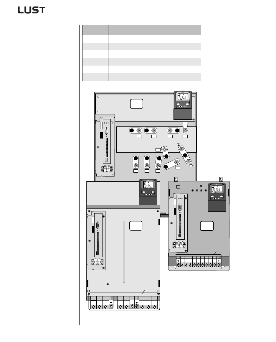
Te rmina l Explanation
X1 Power connections
X2 Control connections
X3 Motor PTC connection
X4 PC/KP200 connection (RS232 interface)
X6 UM-xxx module connection
X7 CM-xxx module connection
BG8
H1 H2 H3
X7
X4
X6
X2
X3
U V W RB
L+
L1
L2 L3
VAL
Hz
start
stop
enter
return
L-
CDA3000 Operation Manual
VAL
Hz
start
stop
enter
return
H1 H2 H3
X7
X4
X6
X7
X4
X6
X2
BG7
X2
BG6
X3
X3
L1
L-
L3
L+
L2
RB
X1
L1
L3
L2
RB
U
L-
L+
V
W
Figure A.2 Layout of CDA3000 inverter module, sizes 6 to 8
A-16
VAL
Hz
start
stop
enter
return
X1
U
V
W
Page 73
Hinweis zur EN 61000-3-2 DE Notes on EN 61000-3-2 EN
(rückwirkende Netzbelastung durch Oberwellen)
Unsere Frequenzumrichter und Servo-regler sind im Sinne der
EN61000 "professionelle Geräte", so dass sie bei einer Nennanschlußleistung ≤1kW in den Geltungsbereich der Norm fallen.Beim direkten Anschluß von Antriebsgeräten ≤1kW an das
öffentliche Niederspannungsnetz sind entweder Maßnahmen
zur Einhaltung der Norm zu treffen oder das zuständige Energieversorgungsunter-nehmen muß eine Anschlußge-nehmigung
erteilen.
Sollten Sie unsere Antriebsgeräte als eine Komponente in ihrer
Maschine/ Anlage einsetzen, dann ist der Geltungsbereich der
Norm für die komplette Maschine/ Anlage zu prüfen.
Remarque concernant EN 61000-3-2 FR Riferimento ad EN 61000-3-2 IT
(valeurs limites pour courants d'harmonique)
Dans l'esprit de EN61000, nos convertisseurs de fréquence et
régulateurs automatiques sont des "appareils professionnels".
Par conséquent ils tombent sous l'application de la norme lorsque la puissance de raccordement nominale ≤1kW.
Lorsque des appareils d'entraînement sont raccordés directement au réseau public basse tension, il convient de prendre des
mesures pour respecter la norme ou l'entreprise de distribution
d'électricité compétente doit délivrer une autorisation de branchement.
Si vous deviez utiliser nos appareils de branchement comme
composants dans votre machine ou votre installation, il convient
dans ce cas de vérifier le domaine d'application de l'ensemble
de la machine ou de l'installation.
(limits for harmonic current emissions)
Our frequency inverters and servocontrollers are "professional
devices" in the sense of the European Standard EN 61000, and
with a rated power of ≤1kW obtained in the scope of this standard.
Direct connection of drive units ≤1kW to the public low-voltage
grid only either by means of measurements for keeping the
standard or via an authorization of connection from the responsible public utility.
In case our drive units are used as a component of a machinery/
plant, so the appropriate scope of the standard of the
machinery/plant must be checked.
(carico di rete retroattivo tramite armoniche)
I nostri invertitori di frequenza e servoregolatori sono degli
"apparecchi professionali" ai sensi della EN61000 così da
ricadere nel campo di validità della norma con una potenza
nominale di collegamento di ≤1kW. Nel caso di collegamento
diretto di azionamenti da ≤1kW alla rete pubblica di bassa
tensione devono essere applicati dei provvedimenti per il
rispetto della norma oppure ottenere un permesso di
allacciamento da parte dell'ente di energia competente.
Doveste usare i nostri apparecchi di azionamento come
componenti della vostra macchina o del vostro impianto,
controllare il campo di validità della norma per l'intera macchina
o l'impianto.
Page 74

Lust Antriebstechnik GmbH
Gewerbestrasse 5-9 • D-35631 Lahnau
Tel. 0 64 41 / 9 66-0 • Fax 0 64 41 / 9 66-137
Internet: http://www.lust-tec.de • e-mail: [email protected]
ID no.: 0840.00B.4-00 • 05/2003
Technische Änderungen vorbehalten.
We reserve the right to make technical changes.
Sous réserve de modifications techniques.
Ci riserviamo il diritto di apportare modifiche tecniche.
 Loading...