

Page 1

xPONENT® 4.0 SP1™
Lum/nex
®
Software Manual
Page 2

© Luminex Corporation, 2001-2009. All rights reserved. No part of this publication may be
reproduced, transmitted, transcribed, or translated into any language or computer language, in any form
or by any means without prior express, written consent of:
LUMINEX CORPORATION
12212 Technology Boulevard
Austin, Texas 78727-6115
U.S.A.
Voice: (512) 219-8020
Fax: (512) 219-5195
Luminex® xPONENT® Software Manual
PN 89-00002-00-185 Rev. C
September 2009
REP
EC
MDCI Ltd.
Arundel House
1 Liverpool Gardens,
Worthing
West Sussex BN11 1SL
United Kingdom
Luminex Corporation (Luminex) reserves the right to modify its products and services at any time. This guide
is subject to change without notice. Although prepared to ensure accuracy, Luminex assumes no liability for
errors or omissions, or for any damages resulting from the application or use of this information.
The following are registered trademarks of Luminex: Luminex®, FLEXMAP 3D™, xMAP®, xPONENT®,
xTAG® Microspheres.
All other trademarks, including Windows®, Cheminert®, Pentium®, and Dell® are trademarks of their
respective companies.
Page 3

Standard Terms and Conditions For Use of Product
By opening the packaging containing this product ("Product") or by using such Product in any manner, you
are consenting and agreeing to be bound by the following terms and conditions. You are also agreeing that
the following terms and conditions constitute a legally valid and binding contract that is enforceable against
you. If you do not agree to all of the terms and conditions set forth below, you must promptly return the Product for a full refund prior to using them in any manner.
1. Acceptance - ALL SALES ARE SUBJECT TO AND EXPRESSLY CONDITIONED UPON THE
TERMS AND CONDITIONS CONTAINED HEREIN, AND UPON BUYER'S ASSENT THERETO. NO
VARIATION OF THESE TERMS AND CONDITIONS SHALL BE BINDING UPON LUMINEX
CORPORATION ("LUMINEX") UNLESS AGREED TO IN WRITING AND SIGNED BY AN
AUTHORIZED REPRESENTATIVE OF LUMINEX. For purposes of this agreement, "Seller" shall
mean the Luminex authorized reseller that sells the Product to Buyer. Buyer, by accepting the Product
shall be deemed to have assented to the terms and conditions set forth herein, notwithstanding any
terms contained in any prior or later communications from Buyer and whether or not Seller shall
specifically or expressly object to any such terms.
2.
Warranties - Any warranty obligations for the Product shall be exclusively provided in writing to
Buyer directly by Seller. LUMINEX MAKES NO WARRANTY WHATSOEVER REGARDING THE
PRODUCT AND LUMINEX SPECIFICALLY DISCLAIMS ALL WARRANTIES, EXPRESS OR
IMPLIED, INCLUDING ANY IMPLIED WARRANTY OF MERCHANTABILITY OR FITNESS FOR A
PARTICULAR PURPOSE. NEITHER SELLER NOR LUMINEX SHALL IN ANY EVENT BE LIABLE
FOR INCIDENTAL, CONSEQUENTIAL OR SPECIAL DAMAGES OF ANY KIND RESULTING FROM
ANY USE OR FAILURE OF THE PRODUCT, EVEN IF SELLER OR LUMINEX HAS BEEN ADVISED
OF THE POSSIBILITY OF SUCH DAMAGE INCLUDING, WITHOUT LIMITATION, LIABILITY FOR
LOSS OF WORK IN PROGRESS, DOWN TIME, LOSS OF REVENUE OR PROFITS, FAILURE TO
REALIZE SAVINGS, LOSS OF PRODUCTS OF BUYER OR OTHER USE OR ANY LIABILITY OF
BUYER TO A THIRD PARTY ON ACCOUNT OF SUCH LOSS, OR FOR ANY LABOR OR ANY
OTHER EXPENSE, DAMAGE OR LOSS OCCASIONED BY SUCH PRODUCT INCLUDING
PERSONAL INJURY OR PROPERTY DAMAGE UNLESS SUCH PERSONAL INJURY OR
PROPERTY DAMAGE IS CAUSED BY SELLER'S GROSS NEGLIGENCE.
3.
Buyer's Use of Product - Buyer agrees that no rights or licenses under Luminex's patents shall be
implied from the sale of the Product, except as expressly provided herein, and Buyer does not receive
any right under Luminex's patent rights hereunder. Buyer acknowledges and agrees that the Product
is sold and licensed only for use with Luminex's standard fluorescently dyed microspheres. Buyer
further acknowledges that the Product have not received approval from the United States Food and
Drug Administration or other federal, state or local regulatory agencies and have not been tested by
Seller or Luminex for safety or efficacy in food, drug, medical device, cosmetic, commercial or any
other use, unless otherwise stated in Luminex or Seller's technical specifications or material data
sheets furnished to Buyer. Buyer expressly represents and warrants to Luminex that Buyer will
properly test and use any Product in accordance with the practices of a reasonable person who is an
expert in the field and in strict compliance with the United States Food and Drug Administration and
all applicable domestic and international laws and regulations, now and hereinafter enacted.
BUYER HEREBY GRANTS TO LUMINEX A NONEXCLUSIVE, WORLDWIDE, UNRESTRICTED,
ROYALTY-FREE, FULLY PAID-UP LICENSE, WITH THE RIGHT TO GRANT AND AUTHORIZE
SUBLICENSES, UNDER ANY AND ALL PATENT RIGHTS IN INVENTIONS COMPRISING MODIFICATIONS, EXTENSIONS, OR ENHANCEMENTS MADE BY BUYER TO THE PRODUCT OR TO
THE MANUFACTURE OR USE OF THE PRODUCT ("IMPROVEMENT PATENTS"), TO MAKE,
HAVE MADE, USE, IMPORT, OFFER FOR SALE OR SELL ANY AND ALL PRODUCT; EXPLOIT
ANY AND ALL METHODS OR PROCESSES; AND OTHERWISE EXPLOIT IMPROVEMENT PATENTS FOR ALL PURPOSES. NOTWITHSTANDING THE FOREGOING, "IMPROVEMENT PAT-
Page 4

ENTS" SPECIFICALLY EXCLUDES PATENT CLAIMS CONCEIVED AND REDUCED TO PRACTICE
BY BUYER CONSISTING OF METHODS OF SAMPLE PREPARATION, METHODS OF CONJUGATING PRODUCT TO ANALYTES, THE COMPOSITION OF MATTER OF THE SPECIFIC CHEMISTRIES OF THE ASSAYS DEVELOPED BY BUYER AND METHODS OF PERFORMING THE
ASSAYS (I.E., THE PROTOCOL FOR THE ASSAY).
Buyer has the responsibility and hereby expressly assumes the risk to verify the hazards and to conduct any further research necessary to learn the hazards involved in using the Product. Buyer also
has the duty to warn Buyer's customers, employees, agents, assigns, officers, successors and any
auxiliary or third party personnel (such as freight handlers, etc.) of any and all risks involved in using
or handling the Product. Buyer agrees to comply with instructions, if any, furnished by Seller or
Luminex relating to the use of the Product and not misuse the Product in any manner. Buyer shall not
reverse engineer, decompile, disassemble or modify the Product. Buyer acknowledges that Luminex
retains ownership of all patents, trademarks, trade secrets and other proprietary rights relating to or
residing in the Product.
4.
Buyer's Representations, Release and Indemnity - Buyer represents and warrants that it shall
use the Product in accordance with Paragraph 2, "Buyer's Use of Product," and that any such use of
Product will not violate any law, regulation, judicial order or injunction. Buyer agrees to release,
discharge, disclaim and renounce any and all claims, demands, actions, causes of action and/or suits
in law or equity, now existing or hereafter arising, whether known or unknown, against Seller and
Luminex, and their respective officers, directors, employees, agents, successors and assigns
(collectively the "Released Parties"), with respect to the use of the Product. Buyer agrees to
indemnify and hold harmless the Released Parties from and against any suits, losses, claims,
demands, liabilities, costs and expenses (including attorney, accounting, expert witness, and
consulting fees) that any of the Released Parties may sustain or incur as a result of any claim against
such Released Party based upon negligence, breach of warranty, strict liability in tort, contract or any
other theory of law or equity arising out of, directly or indirectly, the use of the Product or by reason of
Buyer's failure to perform its obligations contained herein. Buyer shall fully cooperate with the
Released Parties in the investigation and determination of the cause of any accident involving the
Product which results in personal injury or property damage and shall make available to the Released
Parties all statements, reports, recordings and tests made by Buyer or made available to Buyer by
others.
5.
Patent Disclaimer - Neither Seller nor Luminex warrants that the use or sale of the Product will not
infringe the claims of any United States or other patents covering the product itself or the use thereof
in combination with other products or in the operation of any process.
Page 5

End-User License Agreement (EULA) for Luminex® Software
This Luminex End-User License Agreement (“EULA”) is a legal agreement between you (either an individual
or a single entity, also referred herein as “you”) the end-user and Luminex Corporation (“Luminex”) regarding
the use of the xPONENT software product provided to you above, which includes computer SOFTWARE and
online or electronic documentation and may include associated media and printed materials (if any) (“SOFTWARE”). The terms also apply to any updates, supplements, web content or internet-based services, such as
remote access.
BY USING THE SOFTWARE, YOU ACCEPT THESE TERMS. IF YOU DO NOT ACCEPT THEM, DO NOT
USE THE SOFTWARE. INSTEAD, RETURN IT TO LUMINEX OR THE LUMINEX AUTHORIZED THIRD
PARTY FROM WHICH YOU PURCHASED THE SOFTWARE FOR A REFUND OR CREDIT. IF YOU COMPLY WITH THESE LICENSE TERMS, YOU HAVE THE RIGHTS TO USE THE SOFTWARE AS SPECIFICALLY SET FORTH BELOW.
1. OVERVIEW. The SOFTWARE is protected by copyright laws and international copyright treaties, as
well as other intellectual property laws and treaties. The SOFTWARE is licensed, not sold.
2. ADDITIONAL LICENSING REQUIREMENTS AND/OR USE RIGHTS.
a) Trial and Conversion. Some or all of the SOFTWARE may be licensed on a trial basis. Your rights
to use trial SOFTWARE are limited to the trial period. The trial SOFTWARE and length of the trial
period are set forth during the activation process. The SOFTWARE may be used for evaluation
purposes only during the trial period and not for any commercial use, including without limitation to
any diagnostic use. You may have the option to convert your trial rights to perpetual rights.
Conversion options will be presented to you at the expiration of your trial period.
b) Activation. You can activate the SOFTWARE by obtaining a license key provided by Luminex
Technical Support at support@luminexcorp.com
c) Branding. You may only add additional branding or other graphics to SOFTWARE with Luminex’s
express written consent.
d) Upgrades. You may only obtain updates or upgrades for the SOFTWARE from Luminex Technical
Support at orders@luminexcorp.com
updates from authorized resellers, see http://www.luminexcorp.com
or authorized resellers. For more information on obtaining
or 1-877-785-2323 or 1-512-381-4397.
.
3. GRANT OF LICENSE. Subject to the terms and conditions of this EULA, Luminex hereby grants to
you a nonexclusive, nontransferable, nonassignable license (without right to sublicense) under
Luminex’s copyrights and trade secrets to use the SOFTWARE on a single computer running with a
single unit of a specific model of Luminex instrument, as such model is identified on the packaging
included with the SOFTWARE. You may make one (1) copy of the SOFTWARE for backup or archival
purposes only. You may also install the SOFTWARE on up to three (3) additional computers for
purposes of performing ancillary tasks (i.e. preparing templates/protocols, performing further analysis
or re-running previous data), provided such computers are at a single location and are NOT
connected with a Luminex instrument. In addition, You may purchase the right to use the SOFTWARE
on additional computers, as agreed to in writing with Luminex or its authorized reseller, for purposes
of performing ancillary tasks (i.e. preparing templates/protocols, performing further analysis or rerunning previous data), provided such computers are at a single location and are NOT connected with
a Luminex instrument. Although no rights or licenses under any of Luminex's patents are granted by
or shall be implied from the license of the SOFTWARE or the sale of Luminex instrumentation to you,
the purchaser, you may obtain a license under Luminex’s patents, if any, to use this unit of Luminex
instrumentation with fluorescently labeled microsphere beads authorized by Luminex by purchasing
such beads from Luminex or an authorized Luminex reseller.
4. RESTRICTIONS
• SOFTWARE must only be installed and operated on a single computer running with a Luminex
instrument, as set forth above.
Page 6

• You may not use this SOFTWARE for any commercial purpose, including in the performance of
testing services, unless expressly agreed to in writing by Luminex or as authorized in writing by
Luminex through an authorized reseller of the SOFTWARE.
• You may only use the SOFTWARE with microspheres manufactured by Luminex or with kits
developed, manufactured and distributed by licensees authorized in writing by Luminex.
• You must maintain all proprietary notices on all copies of the SOFTWARE.
• You may not distribute copies of the SOFTWARE to third parties.
• You may not reverse-engineer, decompile, disassemble, or otherwise attempt to derive source
code from the SOFTWARE.
• You may not copy (other than one backup or archival copy), distribute, sublicense, rent, lease,
transfer or grant any rights in or to all or any portion of the SOFTWARE.
• You must comply with all applicable laws regarding the use of the SOFTWARE.
• You may not modify or prepare derivative works of the SOFTWARE, including modifying any
branding or graphics.
• You may not use the SOFTWARE in a computer-based service business or publicly display visual
output of the SOFTWARE.
• You may not transmit the SOFTWARE over a network, by telephone, or electronically by any
means.
5. TERM AND TERMINATION. Your rights under this EULA are effective until termination. You may
terminate this EULA at any time by destroying the SOFTWARE, including all computer programs and
documentation, and erasing any copies residing on your computer equipment. Luminex may
terminate this EULA upon thirty (30) days written notice to you. Your rights under this EULA
automatically terminate without further action on the part of Luminex if you do not comply with any of
the terms or conditions of this EULA. Upon any termination of this EULA, you agree to destroy the
SOFTWARE and erase any copies residing on your computer equipment.
6. RIGHTS IN SOFTWARE. All rights and title in and to the SOFTWARE and any copies thereof are
owned by Luminex or its suppliers. This EULA is not a sale and does not transfer to you any title or
ownership interest in or to the SOFTWARE or any patent, copyright, trade secret, trade name,
trademark or other intellectual property right therein. You shall not remove, alter, or obscure any
proprietary notices contained on or within the SOFTWARE and shall reproduce such notices on any
back-up copy of the SOFTWARE. All title and intellectual property rights in and to the content which
may be accessed through use of the SOFTWARE is the property of the respective content owner and
may be protected by applicable copyright or other intellectual property laws and treaties. This EULA
grants you no rights to use such content.
7. EXPORT RESTRICTIONS. You agree that you will not export or re-export the SOFTWARE to any
country, person, entity, or end-user subject to U.S.A. export restrictions. You hereby warrant no state
or federal agency has suspended, revoked, or denied your export privileges.
8. NO WARRANTY. THE SOFTWARE IS LICENSED “AS IS.” ANY USE OF THE SOFTWARE IS AT
YOUR OWN RISK. THE SOFTWARE IS PROVIDED FOR USE ONLY WITH LUMINEX PRODUCTS.
TO THE MAXIMUM EXTENT PERMITTED BY APPLICABLE LAW, LUMINEX AND ITS SUPPLIERS
DISCLAIM ALL WARRANTIES, EITHER EXPRESS OR IMPLIED, INCLUDING, BUT NOT LIMITED
TO, IMPLIED WARRANTIES OF MERCHANTABILITY, FITNESS FOR A PARTICULAR PURPOSE,
AND NONINFRINGEMENT.
9. LIMITATION OF LIABILITY. IN NO EVENT SHALL LUMINEX OR ITS SUPPLIERS BE LIABLE FOR
ANY SPECIAL, INCIDENTAL, INDIRECT, OR CONSEQUENTIAL DAMAGES WHATSOEVER
(INCLUDING, WITHOUT LIMITATION, DAMAGES FOR LOSS OF BUSINESS PROFITS, BUSINESS
INTERRUPTION, LOSS OF BUSINESS INFORMATION, OR ANY OTHER PECUNIARY LOSS)
ARISING OUT OF THE USE OF OR INABILITY TO USE THE SOFTWARE, EVEN IF LUMINEX HAS
BEEN ADVISED OF THE POSSIBILITY OF SUCH DAMAGES.
Page 7

10. MISCELLANEOUS. This EULA is governed by the laws of the State of Texas, U.S.A., without
reference to conflicts of laws principles. You shall not assign or sublicense or otherwise transfer the
rights or license granted hereunder, by agreement or by operation of law, without the prior written
consent of Luminex, and all assignments in violation of this prohibition shall be null and void. This
EULA is the complete and exclusive agreement of Luminex and you and supersedes all other
communications, oral or written, relating to the subject matter hereof. No change to this EULA shall
be valid unless in writing and signed by the party against whom enforcement is sought. The waiver or
failure of Luminex or you to exercise in any respect any right or rights provided for herein shall not be
deemed a waiver of any further right hereunder. If any provision of this EULA is held unenforceable,
the remainder of this EULA will continue in full force and effect.
Page 8

Page 9

Table of Contents
Introduction .......................................................................................................................... 1
Software Packages ......................................................................................................... 1
About This Guide ............................................................................................................ 2
Warnings, Notes and Symbols........................................................................................ 2
General Guidelines ......................................................................................................... 3
Biological Samples .................................................................................................... 3
Bead Handling ........................................................................................................... 3
Limitations ............................................................................................................ 3
Safety Precautions ............................................................................................... 4
Bead Concentration................................................................................................... 4
Repetitive xMAP Bead Measurements...................................................................... 4
Classification and Reporter Fluorochromes .............................................................. 4
Sample Volume ......................................................................................................... 5
Sample Dilution ......................................................................................................... 5
Reagents ................................................................................................................... 6
Gating ........................................................................................................................ 6
Plates......................................................................................................................... 6
Touring the Software............................................................................................................ 7
Log In .............................................................................................................................. 7
Help................................................................................................................................. 8
Log Off ............................................................................................................................ 8
Exit .................................................................................................................................. 8
Screen Elements............................................................................................................. 9
System Monitor ............................................................................................................. 10
Home ............................................................................................................................ 12
Samples ........................................................................................................................ 13
Samples Tab ........................................................................................................... 14
Create Sample Tab ................................................................................................. 15
Batches ......................................................................................................................... 16
Batches Tab ............................................................................................................ 16
Create a New Batch from an existing Protocol........................................................ 18
Protocol Tab....................................................................................................... 18
Stds & Ctrls Tab ................................................................................................. 19
Plate Layout Tab ................................................................................................ 21
Create a New Batch From a New Protocol.............................................................. 24
Settings Tab ....................................................................................................... 24
Analytes Tab ...................................................................................................... 27
Stds & Ctrls Tab ................................................................................................. 31
Plate Layout Tab ................................................................................................ 32
Create a New MultiBatch......................................................................................... 33
Results .......................................................................................................................... 37
i
Page 10

Luminex xPONENT 4.0 Software Manual
Current Batch Tab .................................................................................................... 37
3D View............................................................................................................... 41
Saved Batches Tab .................................................................................................. 43
Results Tab......................................................................................................... 48
Settings Tab........................................................................................................ 49
Log Tab............................................................................................................... 50
Sample Details Tab............................................................................................. 51
LIS Results Tab........................................................................................................ 52
Reports Tab.............................................................................................................. 52
Protocols ........................................................................................................................ 55
Protocols Tab ........................................................................................................... 55
Settings Tab........................................................................................................ 56
Analytes Tab ...................................................................................................... 59
Plate Layout Tab................................................................................................. 62
Stds & Ctrls Tab ....................................................................................................... 65
Std/Ctrl Details Tab ............................................................................................. 67
Maintenance .................................................................................................................. 68
Auto Maint Tab ......................................................................................................... 69
Lot Management Tab ............................................................................................... 70
Cmds & Routines Tab .............................................................................................. 71
Probe and Heater Tab.............................................................................................. 75
System Info Tab ....................................................................................................... 77
System Status Tab ................................................................................................... 79
Schedule Tab ........................................................................................................... 80
Support Utility Tab.................................................................................................... 80
Admin............................................................................................................................. 82
System Setup Tab.................................................................................................... 82
Application Settings............................................................................................. 82
LIS Settings......................................................................................................... 83
External Analysis Program Settings.................................................................... 83
Arrange Main Navigation buttons........................................................................ 84
Maintenance Options .......................................................................................... 85
Data Conversion ................................................................................................. 85
Group Setup Tab...................................................................................................... 85
User Setup Tab ........................................................................................................ 88
Create User Account Screen .............................................................................. 89
Batch Options Tab.................................................................................................... 91
Alert Options Tab...................................................................................................... 93
CSV Options Tab...................................................................................................... 95
CSV and Batch Export Options........................................................................... 95
Archive Tab .............................................................................................................. 97
Licensing Tab ........................................................................................................... 98
Schedule Tab ........................................................................................................... 99
Report Options Tab ................................................................................................ 100
Using the Software ........................................................................................................... 101
Starting the Software ................................................................................................... 101
Using Online Help ........................................................................................................ 101
ii
Page 11

Contents
Setting Administrative Options .................................................................................... 102
System Setup ........................................................................................................ 102
Application Settings.......................................................................................... 102
Arrange Main Navigation Buttons..................................................................... 102
LIS Settings ...................................................................................................... 102
Maintenance Options ....................................................................................... 102
External Analysis Program Settings ................................................................. 102
Data Conversion............................................................................................... 103
Group Setup .......................................................................................................... 104
User Setup............................................................................................................. 104
Define Global User Settings ............................................................................. 104
Adding a User................................................................................................... 105
Editing User Permissions ................................................................................. 105
Restoring Account Status................................................................................. 105
Batch Options ........................................................................................................ 105
Alert Options .......................................................................................................... 105
CSV Options .......................................................................................................... 106
Archive................................................................................................................... 106
Licensing................................................................................................................ 107
Schedule................................................................................................................ 107
Report Options....................................................................................................... 107
Adjusting the Sample Probe........................................................................................ 108
System Initialization .................................................................................................... 108
Run System Initialization ....................................................................................... 109
Add CAL or VER Kits............................................................................................. 109
Import CAL or VER Kits ......................................................................................... 110
Export CAL or VER Kits......................................................................................... 110
Delete CAL and VER Kit Information..................................................................... 110
Create Calibration Reports .................................................................................... 110
Managing Sample Lists............................................................................................... 110
Create New Sample List ........................................................................................ 111
Edit Sample Lists ................................................................................................... 111
Setting Up Batches ..................................................................................................... 111
Create a New Batch from an Existing Protocol...................................................... 112
Create a New Batch from a New Protocol ............................................................. 112
Create a Multi-Batch .............................................................................................. 114
Import Batch .......................................................................................................... 114
Export Batch .......................................................................................................... 114
Delete Batch .......................................................................................................... 115
Edit Batch .............................................................................................................. 115
Run Batch .............................................................................................................. 115
Performing Analysis .................................................................................................... 115
Analyze Current Batch........................................................................................... 116
Manage Saved Batches......................................................................................... 116
Replay Batch .................................................................................................... 116
Analyze Saved Batch ....................................................................................... 117
View and Print Reports .......................................................................................... 119
iii
Page 12

Luminex xPONENT 4.0 Software Manual
Transmit a Batch .................................................................................................... 119
Using Protocols, Lots, and Kits .................................................................................... 119
Protocols................................................................................................................. 119
Create Qualitative Assay Protocol .................................................................... 120
Edit Qualitative Analysis Settings...................................................................... 120
Create Quantitative Assay Protocol .................................................................. 121
Edit Quantitative Analysis Settings ................................................................... 122
Create an Allele Call Protocol ........................................................................... 123
Import Protocol.................................................................................................. 124
Add New Lot for Protocol .................................................................................. 124
Delete Protocol.................................................................................................. 124
Export Protocol.................................................................................................. 124
Edit Protocol...................................................................................................... 125
Lots and Kits........................................................................................................... 125
Create Kit .......................................................................................................... 125
Create Lot ......................................................................................................... 125
Import Lot.......................................................................................................... 126
Delete Lot.......................................................................................................... 126
Export Lot.......................................................................................................... 126
Edit Lot.............................................................................................................. 126
Performing System Maintenance................................................................................. 126
Performing Individual Maintenance Commands..................................................... 126
Perform System Calibration.................................................................................... 127
Manage Maintenance Routines.............................................................................. 127
Create New Routine.......................................................................................... 127
Edit Routine....................................................................................................... 127
Run Routine ...................................................................................................... 128
Delete Routine .................................................................................................. 128
Import Routine................................................................................................... 128
Export Routine .................................................................................................. 128
Support Utility ......................................................................................................... 128
Shutting Down the Analyzer......................................................................................... 129
Logging Out of the Software ........................................................................................ 129
Exiting the Software ..................................................................................................... 129
Technical Support ........................................................................................................ 129
Luminex Website ......................................................................................................... 129
Glossary............................................................................................................................ 131
Index ................................................................................................................................. 137
iv
Page 13

CHAPTER 1 Introduction
The Luminex system was developed to improve workflow and efficiency in the clinical
laboratory and in research and development. End users in the laboratory must run
microtiter plates using xMAP
Software Packages
based assay kits developed for use with xMAP technology.
®
xPONENT® software has different levels of functionality:
1. Basic - Basic package allows you to perform analysis, create protocols and batches
(both of which can be exported for use with an Instrument Control enabled software
package), review and print reports, and perform Luminex system maintenance.
2. Instrument Control - This configuration allows the application to connect to and
communicate with an instrument identified by a specific serial number.
3. 500 Analyte Support - This configuration gives access to run or replay a batch that
contains up to 500 analytes.
4. Secure - Has all of the Basic functionality, plus allows the administrator to set up user
permission levels.
5. 21 CFR Part 11 - Has all of the Secure functionality, plus allows the requirement of
electronic signatures to perform certain tasks. Electronic signatures are listed in the
system log. Electronic signatures for batch functions are also listed in the batch audit
log.
6. Automation - Has the ability to communicate with external hardware.
7. Remote Web Monitoring - Allows you to view alerts and system status via a webpage.
8. LIS - Has the ability to communicate with an external Laboratory Information System
(LIS) database. The LIS edition allows the export of patient result data in ASTM file
format and the import of patient sample information in ASTM format.
9. Allelic Ratios - A feature enabling allelic ratios to be utilized.
You will need an instrument control license to operate the instrument.
For more information on purchasing upgraded packages or to obtain specific package
documentation, contact your vendor.
1
Page 14
Luminex xPONENT 4.0 Software Manual
About This Guide
The conventions in this document assume a basic familiarity with computers and a
knowledge of Microsoft
more than one method, such as from the toolbar and from menus that appear when rightclicking an area of the screen. However, for ease of use the individual procedures in this
manual describe only one method for accessing commands.
This guide is formatted as a PDF, and can be printed. However, the guide is best viewed
online due to the bookmarks and hypertext included in the text.
This guide may be updated periodically. To ensure that you have a current version, access
www.luminexcorp.com/support/tech_manuals.html. The most recent version of this guide,
as well as all translations of this guide, are available for download at that URL.
Warnings, Notes and Symbols
The following informational notes and warnings appear as necessary in this manual.
Windows® software. Commands are often available through
®
NOTE: This message is used to provide general helpful information. No
safety or performance issues are involved.
CAUTION: This message is used in cases where the hazard is minor or only
a potential hazard is present. Failure to comply with the caution
may result in hazardous conditions.
WARNING: This message is used in cases where danger to the operator or to
the performance of the instrument is present. Failure to comply
with the warning may result in incorrect performance, instrument
failure, invalid results, or hazard to the operator.
You may encounter these symbols during the use of xPONENT software. They represent
warnings, conditions, identifications, instructions, and regulatory agencies.
TABLE 1. Symbols
Warning,
Biological
Hazard
General
Warning,
Caution, Risk
of Danger
Heat/Hot
Surface Warning
European
Representative
Manufacturer
2
Page 15

Introduction
General Guidelines
Modifying or deleting xPONENT® system files may cause degradation to system
performance. You can repair modified or deleted xPONENT system files by uninstalling
and re-installing the xPONENT software.
Use of unauthorized third party software with xPONENT software may result in corruption
or failure of the xPONENT software. Use third party software at your own risk.
If using a screen saver on the xPONENT system, be aware that xPONENT will prevent it
from activating. A dialog box will display each time xPONENT is launched, recommending
that the screen saver and any power management settings are turned off.
This system contains electrical, mechanical, and laser components that, if handled
improperly, are potentially harmful. In addition, biological hazards may be present during
system operation. Therefore, we recommend that all system users adhere to standard
laboratory safety practices. The protection provided by the equipment may be impaired or
the warranty voided if Luminex FLEXMAP 3D™ is used in a manner not specified by the
instructions or by Luminex Corporation.
Biological Samples
Human and animal samples may contain biohazardous infectious agents. Where
exposure to potentially biohazardous material, including aerosol, exists, follow appropriate
biosafety procedures and use personal protective equipment - gloves, gowns, laboratory
coats, face shields, or mask and eye protection - and ventilation devices. Observe all
local, state, and federal biohazard handling regulations when disposing of biohazardous
waste material.
Bead Handling
xMAP beads come in various configurations. Avoid excessive agitation of the product to
reduce foaming and surface precipitation. The xMAP beads will settle if left undisturbed.
Always ensure that the xMAP beads are homogeneously resuspended prior to dispensing.
The uncoupled xMAP beads are not monodispersed and tend to aggregate until coated.
Multiple pipetting from the original container may affect bead concentrations. Protect the
xMAP beads from light at all times. Store xMAP beads at 2 to 8°C.
NOTE: Refer to the product information sheet that accompanies your
xMAP beads or assay for additional information.
Limitations
xMAP beads are susceptible to photobleaching; photobleaching effects are cumulative.
Minimize exposure of xMAP beads to light during your development and manufacturing
phases to maintain product integrity.
xMAP beads are hydrophobic in the aqueous medium provided and will settle if left
undisturbed. Resuspend prior to dispensing.
Do not use this product with strong organic solvents. For information on specific
compatibility, visit the Luminex Technical Support website at www.luminexcorp.com. From
the main page, click Support, then FAQs.
3
Page 16

Luminex xPONENT 4.0 Software Manual
Safety Precautions
All samples should be regarded as potentially contaminated and treated as infectious.
These samples should be handled at the Biosafety Level 2 as recommended for any
potentially infectious human serum or blood specimen in the Center for Disease Control/
National Institutes of Health Manual, “Biosafety in Microbiological and Biomedical
Laboratories” 1984.
Although beads do not contain hazardous or carcinogenic components at toxic levels, they
may be toxic if swallowed. Contact with acids liberates toxic gases. If product comes in
contact with skin, wash immediately with copious amounts of water. In case of accident,
seek medical advice immediately and show the product label or container to your medical
provider. A Material Safety Data Sheet is available upon request.
WARNING: Reagents may contain sodium azide as a preservative. Sodium
azide may react with lead and copper plumbing to form highly
explosive metal azides. It is also highly toxic and rates a material
safety data sheet (MSDS) health hazard 4. On disposal, flush
drains with a generous amount of cold water to prevent azide
build-up. Consult the manual guideline “Safety Management No.
CDC-22, Decontamination of Laboratory Sink Drains to remove
Azide salts” (Centers for Disease Control, Atlanta, Georgia, April
30, 1976).
CAUTION: The sheath fluid and the solution in which beads are stored
contain proclin, which may cause an allergic reaction. Use
personal protective equipment, including gloves and safety
glasses.
Bead Concentration
The concentration of beads in an assay is a factor in system speed. If running an xMAPbased kit, follow the instruction found on the kit’s product insert or use the provided
software protocol. We generally recommend using 2000 to 5000 beads per target,
depending on the assay.
Repetitive xMAP Bead Measurements
In an xMAP assay, the reporter signal is the result of the assay. Due to small bead size,
xMAP bead suspension exhibits near solution phase reaction kinetics. This means that
each set of xMAP beads used for a particular assay will show a statistically even
distribution of reporter molecules bound to the surface of each bead. During data
acquisition, numerous beads of each set are analyzed and the median statistic is
computed for that set by the software. The more beads of a set measured, the more
confidence that can be given for that particular measurement. If running an xMAP-based
kit, follow the kit’s product insert or use the provided software protocol.
Classification and Reporter Fluorochromes
Each xMAP bead set is internally dyed with two classification dyes, or three dyes for
beads above 100-plex. The fluorescence signal of these dyes allows for classification of
each bead set. Since each bead is analyzed individually, even when the sets are mixed in
a multiplex assay they can still be distinguished by their emission signals. The
fluorescence signal of reporter molecules bound to the surface of each bead set is
4
Page 17

Introduction
measured and used to determine the result of each assay in a multiplex. Again, since
each bead is analyzed individually, reporter signals for each bead set can be accurately
quantified.
The following table displays acceptable reporter fluorochromes and their excitation and
emission wavelengths.
TABLE 2. Reporter Fluorochromes Wavelengths
R-Phycoerythrin Alexa 532
Formula weight (Daltons) 240,000 470
Absorbance max (nm) 480, 546, 565 531
Extinction max (M-1cm-1) 1,960,000 83,800
Emission max (nm) 578 554
Quantum yield 0.82 0.8
Sample Volume
Sample volumes or sample sizes range from 10 to 200 µL. Ensure that some sample
remains in the well after aspiration; about 25 µL greater than the sample volume. This
amount may vary depending on the type of plate used. After acquisition, the Luminex
analyzer washes the sample lines resulting in ejection of approximately 150 µL of sheath
fluid back into the well for a 96-well plate. Ensure that there is room to add this amount to
the well without overflowing and contaminating other wells.
The volume restrictions on the assay design can be expounded by the following formula:
Total well volume (µL) – Sample uptake volume (µL) + 150 (µL) <Maximum Well Volume
(µL)
• Total well volume = Starting sample volume of a well before the unit samples for
acquisition. Well volume is determined by the consistency of the bead set.
• Sample uptake volume = Uptake volume for acquisition (program this in the protocol as
sample volume).
• 150 (µL) = Volume expelled back as stated in the above paragraph.
• Maximum well volume plate = The maximum volume capacity of the wells in a selected
96-well microtiter plate.
NOTE: This sample volume information is for a 96-well plate. For
information regarding 384-well plates, refer to the assay kit
instructions or contact Luminex technical support.
Sample Dilution
Dilute concentrated biological samples, such as plasma or serum, at least 1:5 with
reagents as part of assay setup or as a final dilution step. If running an xMAP-based kit,
follow the dilution instructions found on the kit’s product insert.
5
Page 18

Luminex xPONENT 4.0 Software Manual
Reagents
Formulated reagents must be free of particulates other than xMAP beads. Do not dilute
xMAP calibrators or verifiers.
Gating
Gate positions are dependent upon buffer composition. Any changes made to the buffer
composition in an assay may result in a different optimal gate location.
Determine the gating on the Doublet Discriminator channel for the assay during assay
development. The numeric values appear on the left side of the histogram. Use the
numerical gate position, as determined during assay development, to set the gate location
in the protocol.
Gating information may change with a new lot of xMAP beads. Each time you receive a
new lot of xMAP beads, evaluate them with the current protocols. If gating information
changes, create a new protocol identical to the current protocol, but with a new version
number and new gating information. If running an xMAP-based kit, follow the instructions
found on the kit’s product insert or use the provided software protocol.
Plates
When using uncovered plates, use black opaque plates, if possible, to reduce
photobleaching.
For heated assays, use CoStar
plates; Eppendorf
well heated assays, we also recommend the plate be covered with a pierceable foil plate
sealer.
For nonheated assays, select a 96-well plate or 384 well plate with an overall height no
greater than one inch (25.4 mm). See “Bead Concentration” on page 4.
See the recommended consumables list on the Luminex website at http://
www.luminexcorp.com/support/recommendedmaterials/index.html for more information.
384-well plates, catalog number 951020737 or equivalent. For 384-
®
Thermowell® 96-well, thin-wall polycarbonate, model P
®
6
Page 19

CHAPTER 2 Touring the Software
This chapter explores each section of the software and its functionality. For information
about using the software, see “Using the Software” on page 101.
This chapter describes default views. Please note that views can be changed and
functionality can be disabled by the xPONENT
system administrator.
®
Log In
To log in, type your user ID at the System Login tab. If you are using the secure version of
the software, type your password. Once you have logged in, the Home page opens. The
xPONENT system administrator must set up the User ID and initial logon passwords.
Contact your xPONENT system administrator if you have not been assigned a user ID and
password.
NOTE: If a user is locked out of the application, each time the Admin user
logs in, a dialog box opens to notify the Admin user that a user is
locked out.
WARNING: Use of this software by untrained personnel can result in
inaccurate data and test results. It is highly advised that users
read this manual thoroughly before operating the software.
7
Page 20
Luminex xPONENT 4.0 Software Manual
2
1
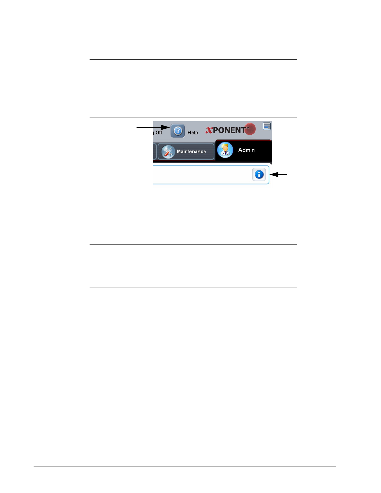
Help
English-language help is available for each window in the software by clicking the blue “i”
button in the upper right portion of the window in which you are working. You can also
access the complete system-wide help by clicking Help at the very top of the screen, and
then clicking Contents and Index.
FIGURE 1. Help Icons
1 System-wide Help 2 Help for current window
Log Off
Click Log Off to log out of the software, then click OK in the Confirm Logout dialog box.
Exit
After you log out, click Exit, then Yes to exit the software completely.
8
Page 21
Touring the Software
2
1
3
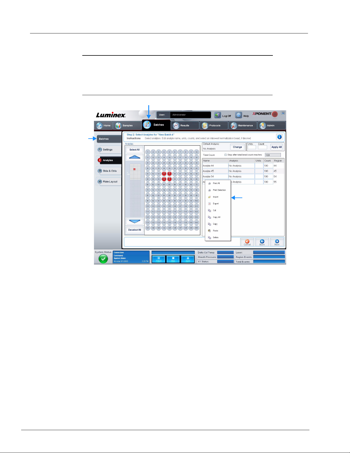
Screen Elements
The following section details the screen elements and the common terms used in this
manual to describe them.
FIGURE 2. Screen Elements
1
Page
3 Right-Click Menu
Page. The main elements at the top of the window are “Pages”. Click a page to go to that
section of the software. All but the Home, and in some cases the Admin, page can be
moved or deleted. For more information, see “System Setup Tab” on page 82.
Tab. The elements on the left side of the window are “Tabs”. Click a tab to go to that
section. Some tabs require you to go in order, and will not let you click a tab further down
without performing a task on the current tab.
Right-Click Menu. Certain sections of the software such as tables, lists, and text boxes
have right-click option menus. Menus are different depending upon the item you rightclicked.
• Print All - Prints all sections or cells of the item.
2 Tab
• Print Selection - Prints only the selected section or cell.
• Import - Imports a file.
9
Page 22
Luminex xPONENT 4.0 Software Manual
12
345
6
7
9
8
• Export - Opens a File Dialog dialog box. Use the Browse button to select a location,
file name, and file type (either a text.CSV file) for the export. This exports all data from
the right-clicked item.
• Cut - Cuts the selected data.
• Copy All - Copies all data.
• Copy - Copies only the selected data.
• Paste - Pastes previously copied text or data into the box.
• Delete - Erases text or data from the selection.
The histogram, dot plot, and 3D View within the Results page have specialty right-click
menus. See those sections for more information.
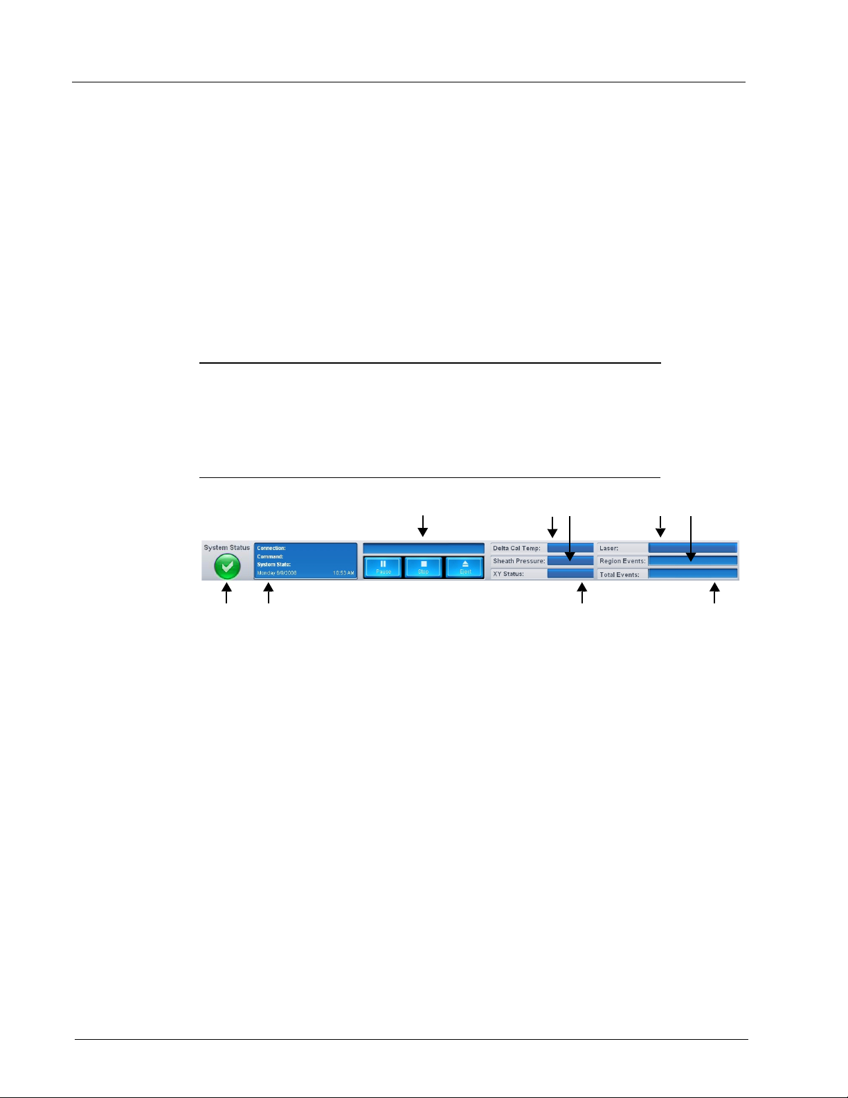
System Monitor
The System Monitor remains at the bottom of all xPONENT® windows. It displays the
physical state of the Luminex analyzer. The values displayed are reported directly from the
Luminex system.
FIGURE 3. System Monitor
10
1 System Status button 2 Command display
3 Progress bar and buttons 4 Delta Cal Temp status button
5 Sheath Pressure status 6 XY status
7 Laser status 8 Region Events status
9 Total events status
System Status. This button has two functions: When clicked, it opens the system log (see
“System Status Tab” on page 79). It also displays the current status of the system. If there
are no warnings or errors, the System Status button is green with a check mark. If there is
a warning, error, or other important user-notification, the button turns yellow with an
exclamation point.
Command. Displays the command currently running on the system.
NOTE: A yellow Check Calibration button is visible in the command
display if the calibration or verification command has failed, when
any verification is not current, or when the calibration or
verification was performed prior to the calibration expiration
setting.
Page 23

Touring the Software
Progress. Displays a bar graph showing the progress of the current command or routine;
if the command or routine is finished, it displays a full progress bar and the command
status as Complete.
Pause. Pauses the system after the current command completes. Pause does not stop
the system in the middle of running a command. You cannot run another command while
the system is paused.
Stop. Stops the system, regardless of command status.
Eject. Ejects the plate. Once the plate is ejected, the Eject button changes to Retract.
Retract retracts the plate, and the Retract button changes back to Eject.
Temp. Displays the difference in temperature between the current reading and the reading
when it was calibrated, in degrees Celsius. If the temperature is out of tolerance, it shows
a high or low arrow. When clicked, it opens the Auto Maint tab.
Sheath Pressure. Displays the sheath pressure in psi. A high or low arrow is displayed if
the pressure is trending up or down versus the calibration pressure and it turns yellow.
When clicked, it opens the System Info tab.
XY Status. Displays the current location of the command, and the temperature of the
plate heating block in degrees Celsius. When clicked, it opens the Probe and Heater tab.
Laser. Displays the laser status, including the time remaining until you must warm up the
laser again. The Laser status button is blue. The button turns yellow when the lasers are
turned off and about ten minutes before they turn off. When clicked, it restarts the active
clock for the laser.
Region Events. Displays the number of bead events detected per second that are
classified in a region.
Total Events. Displays the number of total events detected per second.
11
Page 24
Luminex xPONENT 4.0 Software Manual
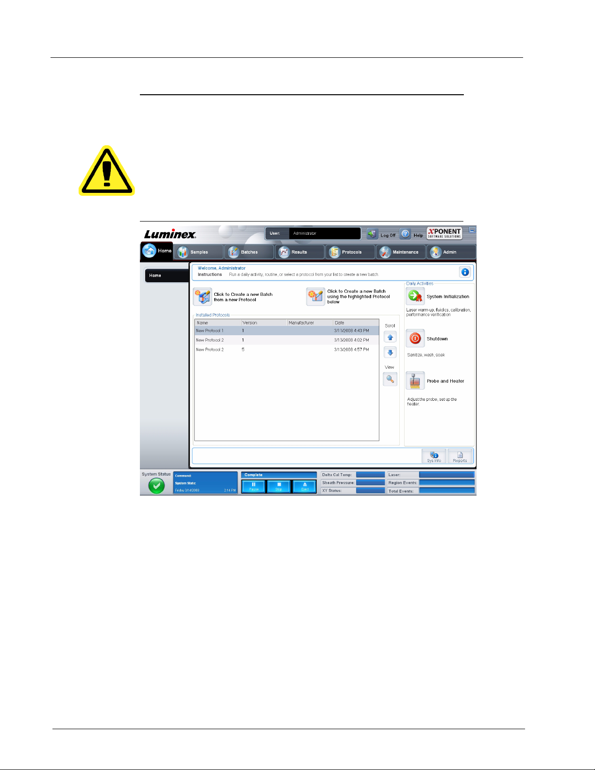
Home
The Home page displays a welcome message, batch creation buttons, Daily Activities
shortcuts, and the Installed Protocols list.
CAUTION: The sheath fluid and the solution in which beads are stored
contain proclin, which may cause an allergic reaction. Use
personal protective equipment, including gloves and safety
glasses.
FIGURE 4. Home Page
12
Return to the Home page at any time by clicking Home in the Navigation toolbar. This
page contains the following:
Click to Create a new Batch from a new Protocol. Creates a new batch from a new
protocol by opening the Settings tab of the Batches page. Users can create protocols on
the fly as a batch is created, and will have the option to save the protocol before or after
the batch is run. For more information, see “Create a New Batch From a New Protocol” on
page 24.
Click to Create a new Batch using the highlighted Protocol below. Creates a new
batch using a selected protocol from the Installed Protocols list. For more information
about creating a batch from an existing protocol, see “Create a New Batch from an
existing Protocol” on page 18.
Page 25

Touring the Software
Installed Protocols. Displays a list of protocols. The list contains the following information
about each protocol:
• Name
• Version
• Manufacturer
• Date
Use the up and down arrows on the right to move through the list of protocols.
View. Opens the Settings tab of the Protocols page to view the selected protocol. This
tab enables viewing the settings, analytes, and plate layout for the selected protocol.
Daily Activities. Contains shortcut buttons to common commands in the xPONENT
software:
®
• System Initialization - Opens the System Initialization command in the Auto Maint
tab on the Maintenance page. For more information about this tab, see “Auto Maint
Tab” on page 69.
• Shutdown - Opens the System Shutdown command in the Auto Maint tab on the
Maintenance page. For more information about this tab, see “Auto Maint Tab” on
page 69.
• Probe and Heater - Opens the Probe and Heater tab on the Maintenance page. For
more information about this tab, see “Probe and Heater Tab” on page 75.
Sys Info. Opens the System Info tab of the Maintenance page. For more information,
see “System Info Tab” on page 77.
Reports. Opens the Reports tab of the Results page. For more information, see “Reports
Tab” on page 52.
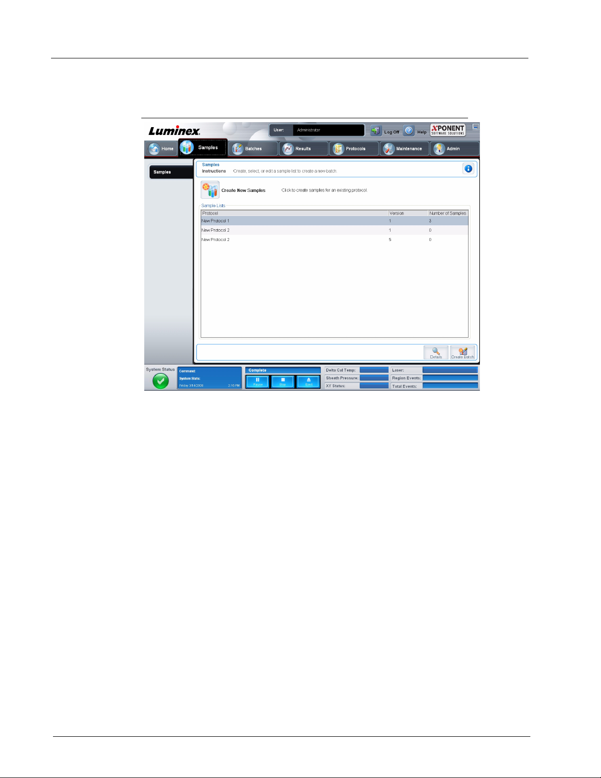
Samples
Use this page to create new samples, view the details of a sample list, or to create a new
batch. Samples can also be added via a Lab Information System (LIS).
This page contains the following tabs:
• Create Sample - Displays when the Create New Samples button is clicked.
• Edit Samples - Displays when the Details button is clicked.
• Protocol - Displays when the Create Batch button is clicked.
• Stds & Ctrls - Displays when the Create Batch button is clicked.
• Plate Layout - Displays when the Create Batch button is clicked.
13
Page 26
Luminex xPONENT 4.0 Software Manual
Samples Tab
FIGURE 5. Samples Tab
This tab contains the following:
Create New Samples. Opens the Create Sample tab.
Sample Lists. Contains a list of protocols, including the version number and the number
of samples associated with each protocol.
Details. Opens the Edit Samples tab to view or edit sample details for the selected
protocol.
Create Batch. Opens the Protocol tab to create a batch.
14
Page 27
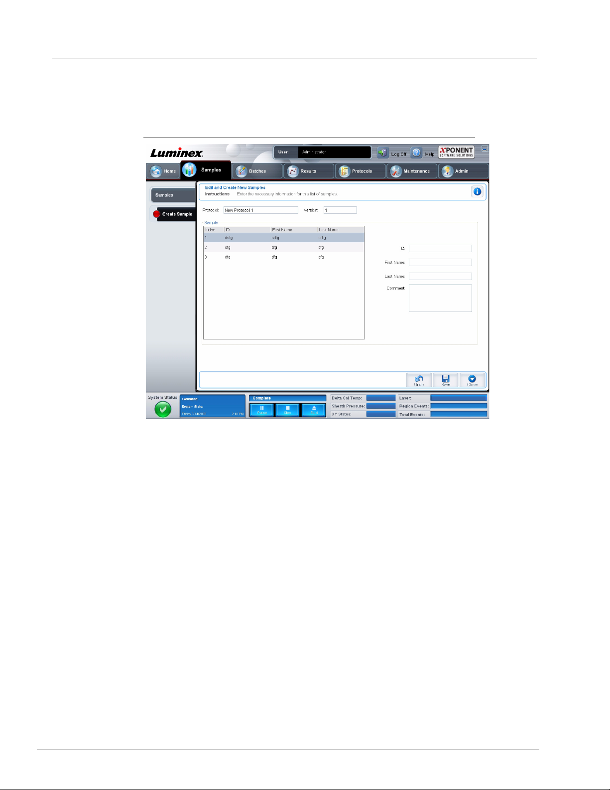
Create Sample Tab
Use this tab to type and view sample information.
FIGURE 6. Create Sample Tab
Touring the Software
This tab contains the following:
Protocol. Displays the protocol selected in the Samples tab. If xPONENT has an LIS
license enabled, any sample details provided by the LIS also appear in the Sample list.
Version. Displays the protocol version number. It is not editable.
NOTE: If a protocol is created using the same name and version as a
previously deleted protocol, previous or pending samples are
relinked to the added protocol.
Sample. If you have the LIS-enabled version of the software and are currently connected
to the LIS, the sample list autopopulates when the LIS provides samples orders. You can
only view or run a sample list created in the LIS; you cannot edit it. Otherwise, use Create
New Samples to create a new sample. Once you have typed and saved the sample
information, it appears in the list to the left. This list displays the samples you have already
created. To reorder the sample’s acquisition location, use the move arrows.
The following Delete, New, Edit, and Undo buttons only display depending on actions
taken in the Create Sample tab.
Delete. Deletes a highlighted sample.
New. Creates a new sample.
15
Page 28
Luminex xPONENT 4.0 Software Manual
Edit. Edits a highlighted sample.
Undo. Reopens the Create Sample tab without saving any changes made using the Edit
or New buttons.
Save. Saves changes made to the Sample list.
Close. Returns to the Samples tab.
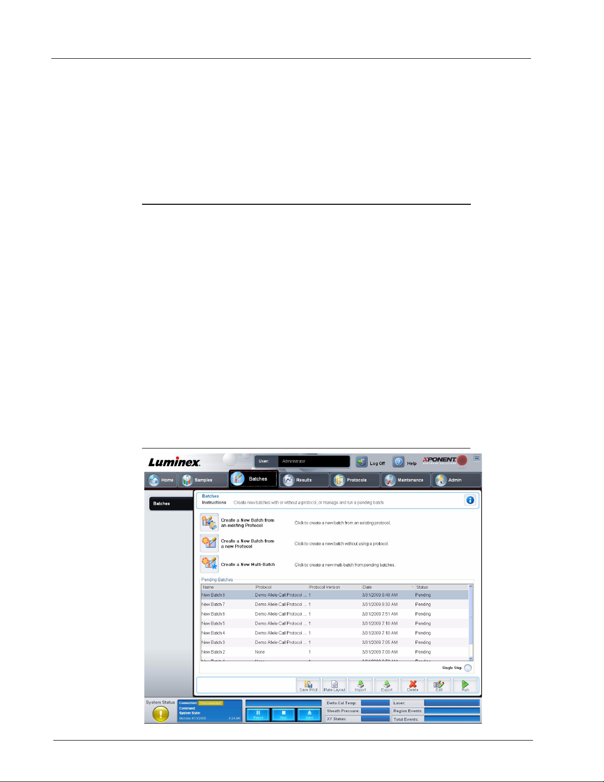
Batches
Use the Batches page to create and run a new batch from an existing protocol, a new
batch from a new protocol, or a new multi-batch. This page contains the following tabs:
• Protocol - Displays when the Create a New Batch from an existing Protocol button
is clicked.
• Stds & Ctrls - Displays when the Create a New Batch from an existing Protocol and
Create a New Batch from a new Protocol buttons are clicked.
• Analytes - Displays when the Create a New Batch from a new Protocol button is
clicked.
• Plate Layout - Displays when the Create a New Batch from an existing Protocol
and Create a New Batch from a new Protocol buttons are clicked.
• New MultiBatch - Displays when the Create a New Multi-Batch button is clicked.
Batches Tab
The Batches tab displays the following:
FIGURE 7. Batches Tab
16
Page 29
Touring the Software
Create a New Batch from an existing Protocol. Opens the Protocol tab, where you
can create a new batch from an existing protocol. For more information, see “Create a
New Batch from an existing Protocol” on page 18.
Create a New Batch from a new Protocol. Opens the Settings tab, where you can
create a new batch from a new protocol. For more information, see “Create a New Batch
From a New Protocol” on page 24.
Create a New Multi-Batch. Simultaneously opens the New Multibatch tab and the
Select Pending Batch dialog box, where you can create a multi-batch from pending
batches. For more information, see “Create a New MultiBatch” on page 33.
Pending Batches. Displays a list of pending batches. It includes the batch name,
protocol, protocol version, date, and status for each pending batch. If there is no data in
the list of pending batches, the following buttons do not appear on the screen.
Single Step. Instructs the system to acquire two wells and then pause. This ensures the
system is working correctly before running an entire batch.
Save Prtcl. Saves a protocol and or assay standard/control information.
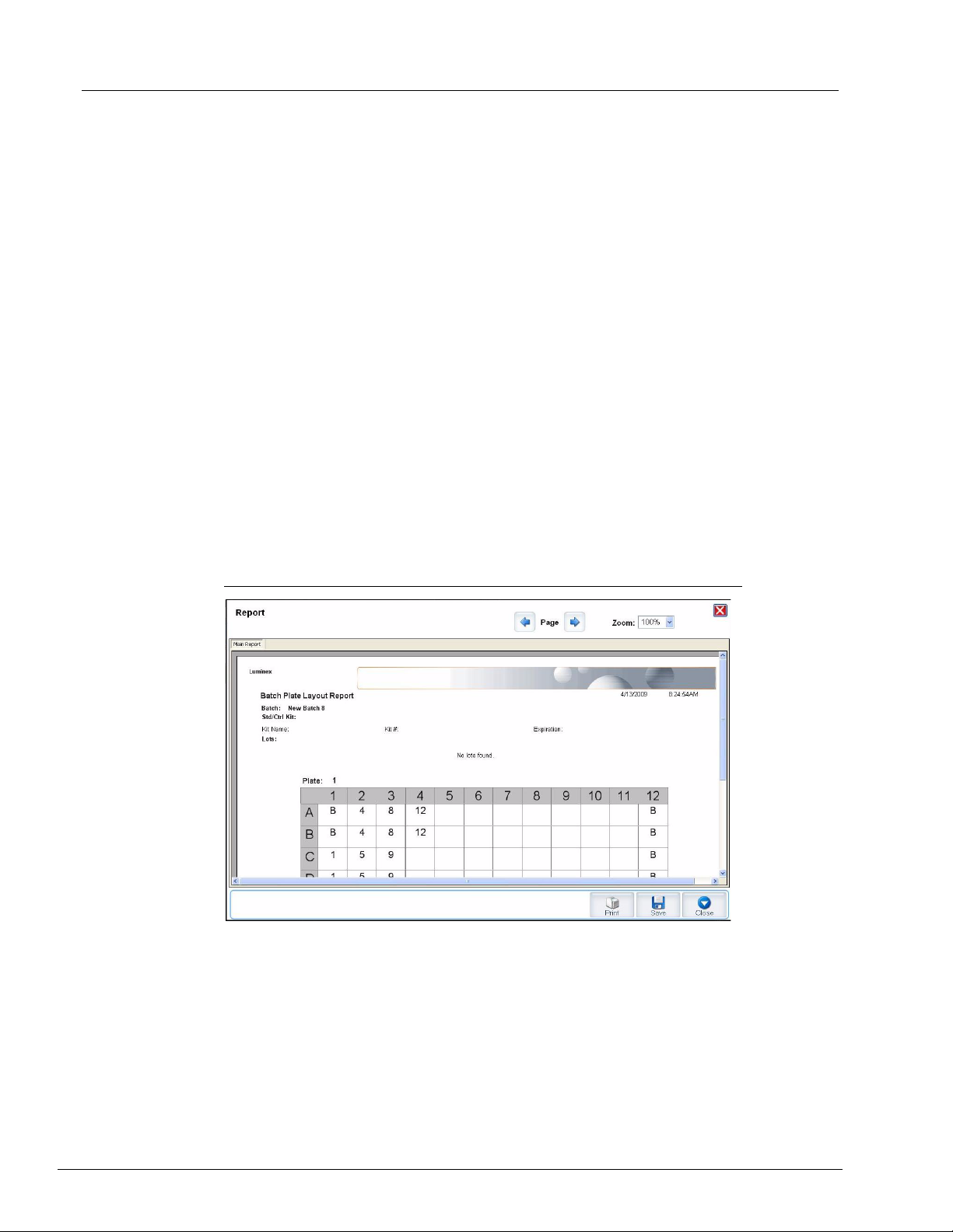
Plate Layout. Opens the Report dialog box, which includes the Batch Plate Layout
Report. See Figure 8 on page 17.
FIGURE 8. Batch Plate Layout Report
Import. Imports a batch.
Export. Exports a batch.
Delete. Deletes a batch.
Edit. Edits a batch.
Run. Runs a batch.
17
Page 30
Luminex xPONENT 4.0 Software Manual
Create a New Batch from an existing Protocol
Creates a new batch from an existing protocol. The Protocol tab opens.
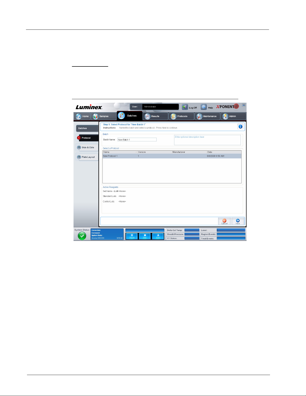
Protocol Tab
Use this tab to name a batch, type a description, select a protocol, and view active
reagents.
FIGURE 9. Protocol Tab
18
This tab contains the following:
Batch Name/Description. Used to name and describe a batch.
Select a Protocol. Contains the protocol name, version, manufacturer, and creation date
for each protocol.
Active Reagents. Displays assay and control lots/kits associated with the selected
protocol. The Standard/Ctrls Kit Name - Lot# field displays the assay standard/control
kit/lot name and lot number currently associated with the selected protocol. The Standard
Lots and Controls Lots fields display any standard or control lots associated with the
selected protocol.
Cancel. Returns to the main Batches tab.
Next. If you have selected a protocol with no standards or controls (Displayed as None in
the Active Reagents section), clicking Next continues to the Plate Layout tab. If you
have selected a protocol with standards and controls, clicking Next continues to the Stds
& Ctrls tab.
Page 31

Stds & Ctrls Tab
Use this tab to apply a kit or lot to the batch.
FIGURE 10. Stds & Ctrls Tab
Touring the Software
This tab contains the following:
Apply Std/Ctrl Kit. Opens the Select Std/Ctrl Kit dialog box. The dialog box displays the
Std/Ctrl Kit Lot #, Std/Ctrl Kit Name, Expiration, and Manufacturer for the kit. Select a
Std/Ctrl kit from the list and then click OK to close the dialog box. The kit information will
display in the boxes to the right of the Apply Std/Ctrl Kit button. The selected kit must be
associated with the same analyte names.
Manually type information by clicking in the Name, Std/Ctrl Kit Lot #, Expiration, and
Manufacturer boxes and typing the information.
Assay Standard Information. Displays the selected standard reagents in a list. The list
displays the Reagent, Name, Lot #, Expiration, Manufacturer, and expected
concentration value of each analyte.
• Apply Std Lot - Opens the Select Lot dialog box. Select a lot from the list and then
click OK to apply the lot.
• Apply Values - Applies a value across or down the Reagent, Name, Lot #,
Expiration, and Analyte fields. Type a value in these fields by double-clicking on
them, and then using one of the two Apply Values arrows to apply that value down or
across the list of analytes.
NOTE: The Dilution list and Apply Dilution button only appear if a
quantitative analysis has been selected.
• Dilution - Contains the following dilution options:
• 1:2 - Halves the standard from each previous iteration.
19
Page 32

Luminex xPONENT 4.0 Software Manual
• 1:10 (Log) - Computes a value of one-tenth of the standard from each previous
iteration.
• 1/2 Log - Creates a 1:3.16 dilution, or half of each 1:10 (Log) from each previous
iteration.
• Alternatively, type a number for your own dilution factor.
• Apply Dilution - Applies the dilution selected in the Dilution list.
NOTE: Click a column header to resort the display.
NOTE: Click the Reagent column header to resort the order from the
highest number standard to standard number one. This is useful
for applying dilutions in which the last standard is the highest
standard.
Assay Control Information. Lists the selected control reagents. The list displays the
Reagent, Name, Lot Number, Expiration, and Manufacturer. Existing control lot
information can be applied or new information can be typed manually.
• Apply Ctrl Lot - Opens the Select Lot dialog box. Select a lot from the list and then
click OK.
• Show Value - Expected, Low, and High set the expected, lowest, or highest
acceptable concentration of the analyte in the sample.
• Apply Values - Applies a value down or across the list of analytes.
Cancel. Returns to the Batches tab.
Back. Returns to the previous tab.
Next. Opens the Plate Layout tab.
20
Page 33

Touring the Software
Plate Layout Tab
Use this tab to define commands that apply to one or more wells. You can define off-plate
and maintenance commands.
FIGURE 11. Plate Layout Tab
This tab contains the following:
Plate Image. This is a representation of the plate. Each well appears as a circle on the
grid. Well commands appear in the appropriate circles as you assign them to wells on the
plate. If using a 384 well plate, the Plate Navigation section in the lower right part of the
window is a bounding box that can be used to display all the wells in the main plate image
at the upper left portion of the window. Click and drag the box to display different portions
of the plate.
Command Sequence. Contains the command sequence for the active plate. The list
includes all active wells, the type of command (Unknown, Standard, Control, Background,
or assigned maintenance command), ID, and dilution factor. Double click the ID field to
type an ID. Double click the Dilution field to type a dilution factor.
A command’s ID and Dilution fields have a blue border around them if they can be double
clicked to type information.
Move Command. These arrows move a selected command up or down in the Command
Sequence list, changing the acquisition order.
Import List. Opens the Open dialog box to import an existing command sequence list.
Replicate Count. Defines a quantity of replicate sets from one to nine.
Grouping. Selects the sequence in which the replicates are laid out in plate wells. The
options are:
21
Page 34

Luminex xPONENT 4.0 Software Manual
• 123123123. . . Lays out one of each replicate set at a time in numerical order.
• 111222333. . . Lays out all the replicates in a set before moving on to the next set in
numerical order.
You can assign the following well commands. Each command is associated with a color.
You can click and drag to highlight a series of wells, click a column or row header to
highlight the entire column or row, or simply click and highlight different wells and then
click a command below to assign that command to all the highlighted wells.
• Unknown (U): Yellow
• Background (B): Purple
• Control (C): Red
• Standard (S): Green
• Wash (W): Blue
The Delete and Start at Well commands are also available to assign as well commands.
Delete removes the well command for the selected well. The Start at Well command
enables you to begin acquisition at a well other than A1.
NOTE: You should first delete all standards from the plate layout if any of
the standards need to be rearranged, and all controls from the
plate layout if any of the controls need to be rearranged.
NOTE: Wells and commands you assign to the protocol plate layout are
saved into the protocol settings and execute each time you use
the protocol to run a batch. Standards and controls associated
with a given protocol typically remain constant, while the number
of unknown wells often vary. You can assign a specific number of
unknown wells to the plate when setting up a batch.
Commands. Assigns maintenance commands that run before or after single wells, ranges
of wells, and rows or columns of wells. Select a well, and then select one of the following
commands:
• Alcohol Flush
• Prime
• Sanitize
• Soak
• Wash
After selecting a maintenance command, click one of the following buttons:
• Before Well - The system performs the command before acquiring the well. An open
dot appears in the upper left corner of the selected well on the plate image. The
command appears in the command sequence list before the selected well.
• After Well - The system performs the command after acquiring the well. A closed dot
appears in the lower right corner of the selected well on the plate image. The command
appears in the command sequence list after the selected well.
• Clear Command - Select a well and click Clear Commands to remove all
maintenance commands from the well.
22
NOTE: If the batch has Before Well or After Well commands samples
will be run as in a standard syringe system, which will lengthen
the batch run time.
Page 35

Touring the Software
Plate. Specifies the plate to display in the plate image in the list. Add Plate adds a new
plate to the batch, and Delete Plate deletes the plate highlighted in the list.
Direction. Specifies the direction to run the plate commands. Select either horizontally or
vertically. The selected direction also dictates how wells are added to the plate when
assigning multiple unknowns, standards, and controls at one time.
Plate Navigation. Displays a smaller plate image for the current batch. If you have
selected a 384-well plate, there is a blue bounding box that can be clicked and dragged to
display the full range of wells in the larger plate image at the upper left.
Single Step. Instructs the system to acquire two wells and then stop. Use this to ensure
the system is working correctly before you run the whole batch.
Off Plate Area. Designates an alternate location for maintenance commands in the
Commands: list. Highlight a command, and then click either a reservoir or strip well in the
Off Plate Area to select a location for the command.
Save Prtcl. Opens the Save Protocol dialog box to save the protocol and or kit.
FIGURE 12. Save Protocol Dialog Box
• Select Save Protocol and/or Save Std/Ctrl Kit to save the protocol and/or kit.
• Type information in the following boxes and click Save to save the protocol or kit.
• Protocol Name
• Version
• Manufacturer
• Optional Description
• Std/Ctrl Kit Name
• Std/Ctrl Kit Lot#
23
Page 36

Luminex xPONENT 4.0 Software Manual
• Expiration
• Manufacturer
Save. Saves the information as a pending batch.
Cancel. Returns to the Batches tab.
Back. Returns to the previous window.
Run Batch. Runs the batch and opens the Current Batch tab, where you can monitor the
batch as it runs.
Create a New Batch From a New Protocol
Click Create a New Batch from a new Protocol to create a new batch without using a
protocol. The Settings tab opens. Raw data results write to a.CSV file. You can define
parameters for samples, gates, regions, events, and commands.
NOTE: If the batch spans more than one plate, the tray ejects
automatically when all defined wells have been acquired. A dialog
box displays prompting you to insert the next plate.
Settings Tab
Use this tab to name your new batch and configure acquisition settings.
FIGURE 13. Settings Tab
24
This tab contains the following:
Page 37

Touring the Software
Name and Description boxes. Type a name and a description in the appropriate boxes.
Acquisition Settings. Use this section to set the following:
• Bead Type - Select either MicroPlex (standard) or MagPlex (magnetic) beads.
• Volum e - This is the volume the instrument will aspirate into the system for analysis.
Type the desired sample volume in microliters. Use values from 10 to 200 µl for both
96-well and 384-well plates. To avoid air intake, add at least 25 µl to the sample well in
addition to the sample size. The default value is 50 µl.
• Timeout - Select Enabled to enable a timeout. Acquisition stops once the timeout is
reached. Type a value from 1 to 250 seconds.
• XY heater - Select Enabled to enable the XY heater. In the box, type the desired value
in degrees Celsius. The temperature range is 35 to 60°C in 0.5 increments.
WARNING: Acquiring data before the heater has reached the proper
temperature can compromise test results.
• Plate Name - Click the Plate Name list and select Current 96-well plate, Current
384-well plate, or a plate that you have previously saved.
• DD gating - Use this to set the minimum and maximum DD gating values. Use values
within the range of 0 to 32767. In the first box, type the minimum value. In the second
box, type the maximum value. The default minimum and maximum values are 7500
and 13500 respectively.
• Reporter Gain - Select Standard PMT from this list to decrease the reporter gain
level. The default option is Enhanced PMT. Refer to assay application instructions for
more detailed information.
Analysis Settings. Use this section to set the analysis type, set the number of standards
and controls, select an external analysis program, and choose whether to analyze results
while acquiring samples.
• Analysis Type - Use this list to choose from the following analysis types:
• None - No analysis. Select if you have your own data post-processing program and
want to obtain only fluorescent intensity results. You cannot apply standards or
controls when you select None. You cannot analyze acquisitions with this setting.
• Qualitative - Qualitative analysis determines results as either positive or negative,
reactive or non-reactive. The software is flexible in defining custom result ranges,
such as negative, low positive, or high positive. Determinations are based on a
single standard. For qualitative analysis the Luminex software uses a specific
algorithm, shown below.
Where FI = Fluorescent Intensity and Ki = a “Quali” value entered in lot information to
determine the value or the qualitative assay standard.
The “Quali” value determines a cutoff or threshold. This, in conjunction with ranges
using the Lum Qual formula or an edited range specific for your assay, helps to
determine qualitative results for unknown samples.
Two predefined formulas using the algorithm are included in the system. You can use
them as is or edit their range values to meet your requirements. For information about
changing the analysis settings, see “Analysis Settings Dialog Box” on page 28 and
“Analysis Settings Dialog Box” on page 29.
25
Page 38

Luminex xPONENT 4.0 Software Manual
• Quantitative - Determines the sample concentrations from standard curves using
regression methods Cubic Spline, Linear, Logistic 4P, and
desired values for standards and controls in the Number of Standards and Number
of Controls boxes. Select either Fit of All Standards or Mean of Replicates for the
calculation of the curve fit.
NOTE: Luminex recommends Fit of All Standards as the most accurate
calculation of the curve fit.
Based on a range of quantitative, numerical results, a threshold range can be applied
to a quantitative analysis, for example, high, low, saturated, and expected.
• Allele Call - Sets analysis for an allele call. Analytes must put in groups of 2, 3, or 4
analytes.
• Min MFI Enabled - Select this box to enable a minimum MFI for the Allele Call
analysis. Type a value in this box to set the minimum MFI for analysis.
• Number of Standards - Click to type the number of standards for the protocol.
• Number of Controls - Click to type the number of controls for the protocol.
• Fit of all Standards - The standard curve will be determined by using each individual
standard replicate when calculating the standard curve. For example if one runs
duplicates of a 7 point standard curve, the software will calculate the standard curve by
using 14 points.
• Mean of Replicates - The standard curve will be determined by averaging the
individual standard replicates when calculating the standard curve. For example if one
runs duplicates of a 7-point standard curve, the software will calculate the standard
curve by using 7 averaged points.
• Analyze Results While Acquiring Samples - The software allows for real-time
viewing of the results as the instrument analyzes samples.
• Use External Analysis Program - Select this check-box to use a third-party program
to analyze the data. The Analysis Program list becomes active when this is selected.
• Analysis Program - Use this list to select which program to use for data analysis.
Logistic 5P. Type the
26
Cancel. Click to return to the main Batches tab.
Next. Click to advance to the Analytes tab.
Page 39

Analytes Tab
Use this tab to select or edit analytes used in the batch or protocol.
FIGURE 14. Analytes Tab
Touring the Software
This tab contains the following:
Analyte grid. A grid representing each analyte from 1 to 500. Drag the slider box at the
far left up or down, or click the blue up and down arrows to display the full range of
analytes. Select All selects all analytes, and Deselect All deselects all analytes. Click a
numbered analyte to select it; click the analyte again to deselect it. You can also click and
drag to select groups of analytes. Selected analytes are red. Deselected analytes are
gray. An analyte marked as an intra-well normalization bead is blue.
Default Analysis. The default analysis changes based on the Analysis Type selected in
the Settings tab. You can change the analysis settings for all analytes by clicking Change
if the button is enabled in this tab. This displays the Analysis Settings dialog box.
27
Page 40

Luminex xPONENT 4.0 Software Manual
FIGURE 15. Analysis Settings Dialog Box
If you selected Quantitative on the Settings tab, the default analysis formula is 5P
weighted. To change the default, select one of the following from the Method list:
• No Analysis
• Cubic Spline
• Linear Fit
• Logistic 4P
• Logistic 5P
If you select Logistic 4P or Logistic 5P, select a weight type of either None or 1/Y
If you selected Qualitative on the Settings tab, the default analysis is Luminex
Qualitative. Change the default value by selecting either Lum Qual or No Analysis.
Click Apply to All Analytes to apply your selection to all selected analytes. Click OK to
change the default analysis to the analysis you selected. Click Cancel to close the dialog
box without saving. For more information, see “Analysis Settings” on page 25.
Units. Type the desired units for the analytes in this box.
Count. Type the desired bead count for the analytes by clicking in the Count box. If each
selected bead set does not acquire this number of events, a warning is added to the log
that not enough bead events were acquired. If you select bead sets that are not present,
the analyzer continues to acquire, trying to reach the number of events per bead for bead
sets that are not in the sample. Therefore, choose only the bead sets present in your
sample.
2
.
28
Apply All. Applies the information in the Units and Count boxes to all analytes.
Page 41

Touring the Software
Total Count. Select Stop after bead count reaches: to stop acquisition when the bead
count reaches a certain number determined by the user. Type the desired value in the box.
The default value is 100.
You can also specify the minimum allowable bead count per well that the xPONENT
software analyzes. This excludes data from any beads carried over during acquisition. For
information about this feature, see “Batch Options Tab” on page 91.
Selected Analytes List. Selected analytes appear in a list on the right side of the analyte
grid. This list includes the following information:
®
• Name - The name of the analyte. Click and type to rename the analyte.
• Analysis - To change the type of analysis for an analyte, click this field to open the
Analysis Settings dialog box and select another analysis from the list.
FIGURE 16. Analysis Settings Dialog Box
• Select a method from the Method list.
• If necessary, select a weight type from the Weight Type list.
• Apply the analysis to all analytes in the list by clicking Apply to All Analytes.
• Select Mark as Intra-Well Normalization Bead to make the analyte an intra-well
normalization bead.
• Add a range to the analysis by clicking Add Range.
• Select Use Threshold Ranges to enable ranges for the analysis.
• Click Add Range to add a range.
29
Page 42

Luminex xPONENT 4.0 Software Manual
• Type a Range Name, a Low Value, a High Value, and select Inclusive if you wish to
include the low and high values in the range. Click OK to exit the dialog box.
• Units - The unit of measurement you specified in the Unit box. Click this box to type a
value for the analyte.
• Count - The total desired bead count for an analyte. Click this box to type a value. The
system continues analyzing until each bead set has met the minimum events as
determined in the Count box above. If you select the Stop after total bead count
reaches: check box and type a total count in the corresponding box, this column does
not appear.
• Region - Refers to the specific analyte selected. It is a number from 1 to 500.
Group. If you have selected Allele Call from the Analysis Type in the Settings tab, this
button displays. Click Group to group 2, 3, or 4 analytes for the group. Multiple groups can
be made.
Cancel. Click Cancel to return to the Batches tab.
Back. Click Back to return to the Settings tab.
Next. Click to go to the next tab. If the Analysis Type selected in the Settings tab was
None or Allele, this takes you to the Plate Layout tab. If the Analysis Type selected was
Quantitative or Qualitative, this button takes you to the Stds & Ctrls tab.
30
Page 43

Touring the Software
Stds & Ctrls Tab
If you have specified standards and controls, use this tab to apply a lot or a kit. For more
information about the functionality of this tab, see “Stds & Ctrls Tab” on page 19.
FIGURE 17. Stds & Ctrls Tab
31
Page 44

Luminex xPONENT 4.0 Software Manual
Plate Layout Tab
Use this tab to select wells to add samples and maintenance commands to the plate. For
more information about the functionality of this tab, see “Plate Layout Tab” on page 21.
FIGURE 18. Plate Layout Tab
32
Page 45

Touring the Software
Create a New MultiBatch
Use this button to add or remove pending batches to the multi-batch set up and to run a
multi-batch. A multi-batch is composed of one or more pending batches which, together,
will fit on one plate. Use the multi-batch feature to conserve plates.
NOTE: You cannot add a batch that forces multiple plates to a multi-batch
operation. When creating or adding batches, ensure your batches
fit on one plate. All batches must use the same plate name
previously defined and adjusted.
FIGURE 19. New Multibatch Tab
33
Page 46

Luminex xPONENT 4.0 Software Manual
FIGURE 20.
This tab contains the following:
Select Pending Batch. Contains a list of all pending batches. The list includes name,
protocol, protocol version, date, and status information for each pending batch. Select the
batch you want to add to the plate. Click OK. A plate layout diagram automatically
populates the wells for the batch. Click Add to open this box again and add additional
batches.
FIGURE 21. Select Pending Batch dialog box
34
Plate layout. Depicts where batches are located on the plate.
Page 47

Touring the Software
FIGURE 22. New Multibatch tab with plate layout displayed
Multi-Batch. Lists pending batches selected for the multi-batch. The list includes name
and “Start at” well.
Plate Layout. Opens the Multibatch Report dialog box that contains:
• Page. Use these arrows to scroll through the report pages.
• Zoom. Select from the list to change the report magnification.
• Print. Prints report.
• Save. Saves report.
• Close. Closes report dialog box.
The Multibatch Plate Layout Report includes the multibatch plate layout, command
number, plate location, command type, sample ID and dilution. The report is date and time
stamped.
35
Page 48

Luminex xPONENT 4.0 Software Manual
FIGURE 23. Multibatch Report dialog box
New Batch. Opens the Create New Batch tab. Create your new batch. Click Save to
return to the New Multibatch tab.
Add. Opens the Select Pending Batch box.Add a batch from the available options,
including batches newly created.The selected batch then appears on the plate layout. If
the batches selected do not fit on the plate, a Multi-Batch error dialog box opens,
indicating you must edit one or more of the selected batches. The Multi-batch feature will
automatically set the batches side-by-side if space remains on the plate. After you add
each batch, the software automatically adds the next batch to the first well of the next
column or row (depending on the plate direction). You can also select a well first, which
places the next batch in your chosen location.
Remove. Removes a selected batch in the Multi-Batch list. The batch will still remain in
the Pending Batches section (This button only appears if you have added a batch to the
Multi-Batch list and selected the batch from the list).
Cancel. Returns to the main Batches tab without saving.
Run. Runs the batch.
36
Page 49

Touring the Software
Results
Once data is collected in a batch, observation and analysis take place in the Results
page. This page contains the following tabs:
• Current Batch
• Saved Batches
• Results
• Settings
• Log
• Sample Details
• LIS Results
• Reports
Current Batch Tab
Use this tab to view results, statistics, and log information related to the current batch, and
to perform statistical analysis on batch results. This tab offers real-time monitoring of batch
sampling during acquisition through a display of sample bead statistics and analytes,
histogram, and dot plot data. The statistics available on this tab are intrawell bead
statistics. They do not describe replicate well assay results.
NOTE: The buttons on this tab may change based on settings chosen by
the user.
FIGURE 24. Current Batch Tab
Statistic. To view a particular statistic for analytes in a batch, select one of the following:
37
Page 50

Luminex xPONENT 4.0 Software Manual
• Median - The point in a data set where there are as many values occurring above it as
there are below it.
• Test Result - The calculated analysis value for quantitative or qualitative assays
derived from standards with known values.
• Range - A sem-quantitative result for a particular numerical result falling between a
predefined set of values such as “Normal” or “Negative”.
• Count - Gated events, if gates are set.
• Net MFI (Median Background) - Net MFI median background.
• Mean - Average of all values in a set of results.
• % CV of microspheres - The measure of relative dispersion within the distribution.
%CV = 100 x Std Dev / Mean
• Standard Deviation - For calculating sample variability or dispersion, Luminex uses
the standard deviation formula.
• Peak - The value that is equal to the largest number of data points within the
distribution. For example, in data set {1,2,2,3,3,3,4,5}, 3 is the peak because it occurs
the largest number of times in the distribution list.
• Trimmed Count*
• Trimmed Mean*
• Trimmed%CV of microspheres*
• Trimmed Standard Deviation*
• Trimmed Peak*
• % CV of Replicates - The measure of relative dispersion within the distribution of
results for replicate samples.
%CV = 100 X Std Dev / Mean
• % Recovery - A measure of how accurately your observed results match your
expected results following regression analysis.
(Observed concentration) / (Expected concentration) x 100%
• Expected Result - The known or expected test result value for a standard or control.
• Control Range - Low - The lowest value for an assay control used to determine pass/
fail criteria for an assay.
• Control Range - High - The highest value for an assay control used to determine
pass/fail criteria for an assay.
• Normalized Net Median - For each analyte in a well the Normalized Net Median
(NNM) = (net median of analyte) / (net median of normalization bead)
• Units - The unit of measure for an analyte, for example, pg/mL.
38
*Trimmed statistics remove the lower and upper five percent of the extreme statistic
values, then use the remaining values for the Mean, Standard Deviation, or %CV
calculations.
The statistics displayed change according to the analysis type selected.
Analyte. Contains a list of analytes run in the batch. Select an analyte to view all statistics
for that analyte.
Current Well. Displays the statistics of the well currently being displayed (This changes to
Displayed Well if viewing a batch using the Open button of the Saved Batches tab).
Single Step. Allows analysis one well at a time. Click to turn function on or off.
Page 51

Touring the Software
Results. Displays statistics related to the batch. Use the up, down, left, and right arrow
buttons to move through the table, or use the scroll bars. The maximize/minimize toggle
button expands the batch table and returns it to the standard size.
Plate. A list of the available plates (if more than one).
WARNING: If using multiple plates, be careful to ensure that plates are used
in the proper order. Failure to do so can result in inaccurate data
and test results.
Histogram/Dot Plot. Displays real-time monitoring of batch sampling during acquisition.
Both the histogram and the dot plot have buttons that enable you to change the default
view:
• Click the maximize button to maximize the graph to fill the whole window. In the
maximized view, use the sliders to zoom in or zoom out. To return to the standard view,
click the minimize button.
If the histogram or dot plot display have been changed to another view (e.g. Progress,
Well Report), click Default to return to the default histogram and dot plot displays.
• The dot plot default display when using 1 to 100 beads shows Classification 1 and
Classification 2. When running more than 100 beads, the default is Classification 2
and Classification 3 axes, and radio buttons are displayed on the right for the
Classification 1 axis slices. To view the dot plot, you must use the default axes. To
display the bead set information, hover over the desired region. Click the upper view
classification button immediately below the maximize button to change the display to
show Classification 2 and Classification 3. This view displays a series of radio
buttons on the right side of the dot plot. When one of the radio buttons is clicked, the
bead regions in view are those in a fixed range of CL1 values plotted against CL2 and
CL3
. Click the bottom view classification button to change back to the default
classification display.
Histogram. The default location of the histogram is the lower left section of the Current
Batch tab. The Doublet Discriminator (DD) displays on the X axis. Events display on the
Y axis. Doublets appear when two beads stick together, creating undesired results. When
you select the gate, two vertical dashed red lines appear. These represent gate positions
determined by the protocol. Once the gate is set, everything outside of it is ignored. For
batches created using an existing protocol, the gate cannot be changed while running the
batch. For new batches created from new protocols, the gate can be changed while
running the batch. Any changes made to the gate while running new protocol batches
immediately affect the visual display of the dot plot and histogram. In addition, changes
made to the gate while running new protocol batches affect the acquisition for all wells
initiated after the change is made. When viewing saved batch data, the gate can be
changed to visually inspect the effect. Only the visual display of the dot plot and histogram
is affected for saved batches, not the acquired data.
NOTE: Gate positions are dependent upon buffer composition. Any
changes made to your assay buffer composition may result in a
different optimal gate location.
Right-click inside the histogram area to access the following options:
• X Axis - Use this function to change the X axis to the following: Doublet Discriminator,
Reporter 1, Classification 1, Classification 2, and Classification 3. Doublet
Discriminator is the default.
39
Page 52

Luminex xPONENT 4.0 Software Manual
NOTE: You can change the X axis of the histogram for troubleshooting
purposes. Use only the default settings in all other instances.
• Gate - Show, create, delete, or move the gate. You can also move the gates by clicking
and dragging the red lines on the histogram.
• Autoscale - Click to automatically adjust the maximum number of events shown on the
Y axis. Click during acquisition to readjust the Y axis scale.
• Set Scale - The Set Scale dialog box displays. Set the maximum number of events
and click OK. The default number of events is 60.
• View - You can choose to view all events, or only gated events.
• Display Mode - Opens the Histogram Options dialog box. Click either Logarithmic
or Linear display. Logarithmic display is the default. Select the Zoom check box for a
magnified view of the histogram.
Dot Plot. The default location of the dot plot is the lower-right section of the Current
Batch tab. The dot plot is a graphical display of real-time data collection. Luminex
recommends using the default settings to collect data.
Right-click inside the dot plot area to access the following options:
• X Axis - Changes the X axis to the following: Doublet Discriminator, Reporter 1,
Classification 1, Classification 2, and Classification 3.
NOTE: You can change the X axis of the dot plot for troubleshooting
purposes. Use only the default settings in all other instances.
• Y Axis - Changes the Y axis to the following: Doublet Discriminator, Reporter 1,
Classification 1, Classification 2, and Classification 3
• View - Choose to view all events or only gated events.
• Display Mode - Select either Logarithmic or Linear display. The software defaults to
Logarithmic display. Click maximize for a magnified view of the dot plot.
• Plot Type - Select either Density Plot or Decaying Plot. The software defaults to
Density Plot, which displays a constant accumulation of events. Contrasting colors
indicate increasing density. The Decaying Plot plots only the last 100 events.
NOTE: The Density Plot allows the visual elimination of data values that
are determined to be insignificant to the display. Luminex
recommends collecting data in Density Plot mode to observe all
collected events. You can only view the Decaying Plot during
batch acquisition.
Right-click inside the dot plot area to access the following options:
Log. Displays a log of system processes. The log includes the following information:
• Date
• Message
• Code
40
Log entries indicating warnings are highlighted yellow. Errors are highlighted in red. Other
log entries are not highlighted. Click the maximize button to maximize the log. The log
expands to fill the whole window. Click minimize to return to the standard size.
Save Image. Opens a Save As dialog box to save a screen capture.
Page 53

Touring the Software
Details. Opens the Results tab, enabling more analysis and results. For more
information, see “Results Tab” on page 48.
Progress. Click to display real-time progress of the well acquisition. Analyte counts are
displayed in a dynamic bar graph as they are acquired. The scroll bar at the bottom of the
Progress display scrolls through the analyte list.
• Maximize - Maximizes the Progress display to fill the window.
• Zoom - Enable a closer look at the analyte progress.
• Save Image - Opens a Save As dialog box to save a screen capture.
• Default - Returns to the histogram and dot plot display.
Well Report. Displays a representation of the plate and the status of acquired wells. Wells
will display one of three possible states:
• Yellow - Well acquired, but the system detects a possible problem (select the Log tab
for more information).
• Green - Well acquired successfully.
• Red - Well acquisition unsuccessful, the system may have stopped, depending on the
circumstances (select Log tab for more information).
3D View. Displays the 3D view of the dot plot.
3D View
The 3D view enables a three dimensional look at the batch results. This view can be
manipulated in a variety of ways to better display regions, specific events, and results
outside expected parameters.
Move the green, purple, and red balls to display only a selection of Classification 3, 2, and
1 data. As you move the balls a square forms in the middle of the 3D view, and excludes
data outside that range.
41
Page 54

Luminex xPONENT 4.0 Software Manual
FIGURE 25. 3D View
3D BeadMap. The main display is the 3D BeadMap. The display shows the CL1, CL2,
and CL3 axes. Left-click and drag your mouse to move the display for better viewing of a
particular section. Right-click anywhere in the display to select from the following viewing
options:
• Display Mode - Select either Logarithmic or Linear. The default is logarithmic.
• Display Position - Select from 3D View, CL1/CL3 View, CL1/CL2 View, or CL2/CL3
View.
• Show Regions - Select from 3D View, CL1/CL3 Plane, Cl2/CL3 Plane, or CL1/CL2
Plane.
• Show Beads - Select from 3D View, CL1/CL3 Plane, CL2/Cl3 Plane, CL1/CL2
Plane.
• View - Select either All Events or Gated Events.
• Cursors - Turns cursors on or off. Cursors are shown as arrows on the display,
allowing you to narrow down the section you wish to view.
3D Region View. This view in the upper right of the window displays a small 3D
representation of the regions. The three axes are shown in the bottom left corner of the
display and can be manipulated by left-clicking and dragging the mouse. Move the slider
on the right to zoom in or out. Enable the 3D Region View Box by clicking Settings for an
easier way to manipulate the viewing angles.
Region. A list that enables viewing of a specific region.
42
View. A list with the options to Show All Events, or Show Gated Events.
Histogram. A smaller histogram display identical to the histogram display in the 2D view.
Save Image. Displays the Save As dialog box to save a screen capture of the 3D display.
Page 55

Touring the Software
Sample Lists. Contains a list of protocols, including the version number and the number
of samples associated with each protocol.
Settings. Opens the 3D Settings dialog box. This dialog box has the following options:
• Show Regions
• 3D
• CL1/CL3 Plane
• CL2/CL3 Plane
• CL1/CL2 Plane
• Show Beads
• 3D
• CL1/CL3 Plane
• CL2/CL3 Plane
• CL1/CL2 Plane
• Display Mode
• Logarithmic
• Linear
• Display Position
• 3D View
• CL1/CL3 View
• CL2/CL3 View
• CL1/CL2 View
• View
• All Events
• Gated Events
• Show Cursors
• Show Region Labels
• Show 3D Region View Box
These settings are also available by right-clicking in the applicable sections of the main 3D
display.
All Regions. Displays all regions of the batch.
2D. Returns to the default display.
Default. Returns to the histogram and dot plot display.
Saved Batches Tab
Use this tab to open a batch that has been run, and view its details, export, approve, or
replay a batch.
43
Page 56

Luminex xPONENT 4.0 Software Manual
Completed Batches. Displays a list of completed batches which includes the Name,
Protocol, Protocol Version, Date, Status, and User information for each batch. This list
does not include batches which have not been run.
FIGURE 26. Saved Batches Tab
Filter. Opens the Filter Setup dialog box.
FIGURE 27. Filter Setup Dialog Box
44
Page 57

Touring the Software
This dialog box lets you choose the saved batches you want to display in the Completed
Batches list based on options you select or clear in the following check boxes:
• Batch Name
• Protocol
• Batch Status
• Lot ID
• Kit ID
• Analyte
• Sample ID
• First Name
• Last Name
• User ID
• Date
Reset - Clears all check boxes.
OK - Closes the dialog box and applies any changes you made.
Cancel - Closes the dialog box and cancels any changes you made.
Save Prtcl. Saves the protocol and kit information for the selected batch. For more
information, see Figure 12 on page 23.
Plate Layout. Opens the Report dialog box, which includes the Batch Plate Layout
Report. See Figure 28 on page 45.
FIGURE 28. Batch Plate Layout Report
Approve. Opens the Batch Approval Confirmation dialog box to approve the selected
batch. Only approved batches can be transmitted to the LIS. If your software is licensed
for LIS use, you can transmit batches to the LIS from the Sample Results tab. Once you
have approved a batch, the status of the batch changes to Approved in the Completed
Batches list.
Exp Results. Opens the Save As dialog box to choose an export destination for the.CSV
file containing your results.
45
Page 58

Luminex xPONENT 4.0 Software Manual
Import. Opens the Open dialog box to choose a batch file (.mdf) to import. Select Include
Raw Files (LXB) to import the raw data file as well.
Export. Opens the Export Batch dialog box to choose a destination for the batch file
(.mdf). Select Include Raw Files (LXB) to include the raw file in the export. Select
Overwrite to overwrite pre-existing files.
Replay. Opens the Select Replay Mode dialog box.
FIGURE 29. Select Replay Mode Dialog Box
Replay batch - Uses the data stored in the run files from the initial acquisition to
reprocess a batch, creating a new batch output file. A batch can be reprocessed multiple
times.
NOTE: The initial batch data and output file always remain intact and
unchanged. Each time you replay a batch, the system handles it
as if it is a new batch, creating a separate batch entry and output
file.
Replay a batch to replay the raw bead data files. The bead data files will be replayed using
the gate, analyte, analysis settings, and plate layout selected in the new (or updated)
protocol. Settings such as bead type, volume, timeout, XY heater, and report gain will
have no effect.
Recalculate data - Reanalyzes the batch results using only the batch’s MFI values.
The batch MFI values will be recalculated using the analysis settings and plate layout
selected in the new recalculated batch or protocol. Settings such as bead type, volume,
timeout, XY heater, gate, report, and gain will have no effect. Because only the MFI values
are reanalyzed, no data will be displayed in the dot plot or histogram.
When you replay or recalculate a batch, you perform the same steps to create the batch
as you did when you created the batch the first time. This sequence will vary based on
whether you created a new batch from a new protocol or a new batch from an existing
protocol. The functionality of the tabs you see while configuring the replay batch is the
same as described in “Batches Tab” on page 16.
46
Page 59

Touring the Software
Open. Opens the Results tab. Use this tab to view the saved batch results for the
selected batch.
47
Page 60

Luminex xPONENT 4.0 Software Manual
Results Tab
FIGURE 30. Results Tab
The Results tab has the same Save Image, Progress, Well Report, and 3-D buttons as
the Current Batch tab. For more information about these buttons, see “Current Batch
Tab” on page 37. The following buttons are added to the Results tab:
• Formula - Opens the Change Analysis dialog box with a list of analytes used in the
batch. Click an analyte to open the Analysis Settings dialog box from which you can
select a new analysis setting for the analyte. For more information, see “Analysis
Settings Dialog Box” on page 28.
• Approve - Opens the Batch Approval Confirmation dialog box, which contains the
data for analytes selected in the Results tab. Click Yes to approve the batch. The
dialog box confirms the approval.
• Validate - Validates an entire selected row or cell in the Results table. Average rows or
cells cannot be selected. If you haven’t selected an item or the item you selected does
not need to be validated, a warning dialog box displays.
• Invalidate - Invalidates an entire selected row or cell in the Results table. The
selection will turn red when invalidated. Select the same item and click Validate to
remove the invalidation status.
• Save - Saves the batch. This button only appears if a change has been made to the
batch.
• Analyze - Analyzes data that has been invalidated. This button only appears if you
have clicked Invalidate on a portion of the data, or if you have clicked Validate on an
invalidated portion of the data. This will analyze the data again with the invalidated
standard removed.
• Close - Closes the batch and reopens the Saved Batches tab.
48
Page 61

Touring the Software
Settings Tab
Use this tab to view the acquisition parameters of the selected saved batch and print the
batch settings report.
FIGURE 31. Settings Tab
Page. Scrolls through the Batch Settings report.
Save. Opens the Save As dialog box to save the Batch Settings report. Select a location
and click OK to save the file. The default save type is a .pdf file.
Print. Prints the report.
Close. Returns to the Saved Batches tab.
49
Page 62

Luminex xPONENT 4.0 Software Manual
Log Tab
This tab displays a log of the activity which occurred during the acquisition of the selected
batch.
FIGURE 32. Log Tab
This tab displays the following information about each activity:
• Date
• Message
• Code
Log entries display yellow if a well was acquired but there was a possible problem. They
display red if a problem occurred during the acquisition.
Print. Prints the log.
Export. Opens the Save As dialog box to save the batch log file. Select a location and
click Save.
Close. Reopens the Saved Batches tab.
50
Page 63

Sample Details Tab
Use this tab to view sample results.
FIGURE 33. Sample Details Tab
Touring the Software
Arrows. Scrolls through the sample details.
Tra nsmit. For systems configured for LIS transmission, select a single analyte or the
entire sample and click Transmit to send the results.
Close. Reopens the Saved Batches tab.
51
Page 64

Luminex xPONENT 4.0 Software Manual
LIS Results Tab
This tab displays saved batches containing LIS samples.
FIGURE 34. LIS Results Tab
Filter. Opens the Filter Setup dialog box. For more information, see Figure 27 on
page 44.
Clear. Click to turn off the filter.
Completed Samples. Displays Name, Protocol, Sample Count, Date, Status, and User
information for each batch displayed in this list.
Tra nsmit. Transmits a batch to an LIS if xPONENT is connected to one.
Details. Opens the Sample Details tab to view sample results.
Reports Tab
Use this tab to view, generate, and print reports.
52
Page 65

FIGURE 35. Reports Tab
Touring the Software
Report and Type lists. Choose a report from one of the following categories:
• Batch Reports - A list of batches appears below the Type list. The list includes Name,
Protocol, Protocol Version, Date, Status, and User information. Choose from the
following reports:
• Data Interpretation
• Batch Settings
• Plate Layout
• Batch Audit
• Patient Report
If you choose Data Interpretation, a Select Analytes section appears on the right and
displays a list of the analytes in the batch. Select the analytes you want to include in the
report. Select All to select all the analytes in the list. Select Clear to clear all the analytes
in the list.
A series of new buttons appears when you click Generate Report:
• Analyte arrows - This feature is directly below the Report list. Use the left and right
arrows to display information for individual analytes of those selected for the report.
• Page arrows - use the arrows to scroll through the pages being displayed.
• Save All - Click to open the Browse For Folder dialog box. Select a location to save
the file, and click OK. This file includes all selected analytes.
• Print All - Click to print the information for all the analytes in the report.
• Save - Click to open the Save As dialog box. Select a location and click Save. This
saves only the analyte information currently being viewed.
53
Page 66

Luminex xPONENT 4.0 Software Manual
• Print - Click to print the analyte information currently being viewed.
• New Report - Click to return to the main Reports window.
NOTE: If running a data interpretation of an allele call batch report, be
aware that when choosing analytes from the Select Analytes list,
selecting one analyte will select all analytes in that group.
• Protocol Reports - A list of protocols displays. Choose from the following reports:
• Protocol Settings
• Plate Layout
• Protocol Audit
Select a protocol and then click Generate to generate the report.
• Calibration and Verification Reports- Displays a list of calibrations and verifications.
Choose from the following selections:
• All
• F3DCAL1
• F3DeCAL1
• F3DCAL2
• F3DCAL3
• F3DVER1
• F3DeVER1
• F3DVER2
Select a calibration component, a date from the Date list, and click Generate to generate
the report.
• Performance Verification Reports - Displays two report types. Choose either of the
following:
• Condensed
• Detailed
Select a report type, a date range from the Date list, and click Generate to generate the
report.
• System Log Reports - Displays a list of system log reports. Choose from the following
selections:
• All
• Maintenance
• Security
• Warning and Errors
Select a system log report, a date from the Date list, and click Generate to generate the
report.
• Advanced Reports - Enables a single option, User Report, in the list.
54
Click Generate to generate the report.
Page 67

Touring the Software
Protocols
The Protocols page enables you to create and edit the settings for protocols, in addition
to adding standards and verifiers. This page contains the following tabs:
• Protocols
• Settings
• Analytes
• Plate Layout
• Stds & Ctrls
Protocols Tab
Use this tab to create, import, export, edit, or delete a protocol. You can also add new
assay standard and or control information using one of the installed protocols.
FIGURE 36. Protocols Tab
This tab contains the following:
Create New Protocol. Opens the Settings tab to create a new protocol. For more
information, see “Settings Tab” on page 56.
Installed Protocols. Displays installed protocols. The list includes Name, Version,
Manufacturer, and Date information for each protocol.
New Std/Ctrl. Opens the Std/Ctrl Details tab. For more information, see “Std/Ctrl Details
Tab” on page 67.
55
Page 68

Luminex xPONENT 4.0 Software Manual
Plate Layout. Opens the Report dialog box, which includes the Plate Layout Report.
See Figure 37 on page 56.
FIGURE 37. Protocols Plate Layout Report
Delete. Opens the Delete Protocol dialog box to delete a protocol selected in the
Installed Protocol list. Click Yes to delete the selected protocol.
Import. Opens the Open dialog box to select a protocol (.lxt file) to import. Navigate to the
protocol file you wish to import and click Open.
Export. Opens the Save As dialog box to export a selected protocol. Choose an export
destination and name, and click Save.
Edit. Opens the Settings tab to edit a selected protocol. For more information, see
“Settings Tab” on page 56.
View. Opens the Settings tab to view the protocol. Click Next to advance to the Analytes
tab, and Next again to advance to the Plate Layout tab. Click Close at any of the three
tabs to return to the main Protocols tab, or Back to return to a preceding tab. The View
option does not allow any changing of the protocol settings.
Settings Tab
Use this tab to name your new protocol and configure acquisition settings.
56
Page 69

FIGURE 38. Settings Tab
Touring the Software
This tab contains the following:
Name and Description boxes. Type a name and a description in the appropriate boxes.
Acquisition Settings. Use this section to set the following:
• Bead Type - Select either MicroPlex (standard) or MagPlex (magnetic) beads.
• Volum e - This is the volume the instrument will aspirate into the system for analysis.
Type the desired sample volume in microliters. Use values from 10 to 200 µl for both
96-well and 384-well plates. To avoid air intake, add at least 25 µl to the sample well in
addition to the sample size. The default value is 50 µl.
• Timeout - Select Enabled to enable a timeout. Acquisition stops once the timeout is
reached. Type a value from 1 to 250 seconds.
• XY heater - Select Enabled to enable the XY heater. In the box, type the desired value
in degrees Celsius. The temperature range is 35 to 60°C in 0.5 increments.
WARNING: Acquiring data before the heater has reached the proper
temperature can compromise test results.
• Plate Name - Click the Plate Name list and select Current 96-well plate, Current
384-well plate, or a plate that you have previously saved.
• DD gating - Use this to set the minimum and maximum DD gating values. Use values
within the range of 0 to 32767. In the first box, type the minimum value. In the second
box, type the maximum value. The default minimum and maximum values are 7500
and 13500 respectively.
• Reporter Gain - Select Standard PMT from this list to decrease the reporter gain
level. The default option is Enhanced PMT. Refer to assay application instructions for
more detailed information.
57
Page 70

Luminex xPONENT 4.0 Software Manual
Analysis Settings. Use this section to set the analysis type, set the number of standards
and controls, select an external analysis program, and choose whether to analyze results
while acquiring samples.
• Analysis Type - Use this list to choose from the following analysis types:
• None - No analysis. Select if you have your own data post-processing program and
want to obtain only fluorescent intensity results. You cannot apply standards or
controls when you select None. You cannot analyze acquisitions with this setting.
• Qualitative - Qualitative analysis determines results as either positive or negative,
reactive or non-reactive. The software is flexible in defining custom result ranges,
such as negative, low positive, or high positive. Determinations are based on a
single standard. For qualitative analysis the Luminex software uses a specific
algorithm, shown below.
Where FI = Fluorescent Intensity and Ki = a “Quali” value entered in lot information to
determine the value or the qualitative assay standard.
The “Quali” value determines a cutoff or threshold. This, in conjunction with ranges
using the Lum Qual formula or an edited range specific for your assay, helps to
determine qualitative results for unknown samples.
Two predefined formulas using the algorithm are included in the system. You can use
them as is or edit their range values to meet your requirements. For information about
changing the analysis settings, see “Analysis Settings Dialog Box” on page 28 and
“Analysis Settings Dialog Box” on page 29.
• Quantitative - Determines the sample concentrations from standard curves using
regression methods Cubic Spline, Linear, Logistic 4P,
desired values for standards and controls in the Number of Standards and Number
of Controls boxes. Select either Fit of All Standards or Mean of Replicates for the
calculation of the curve fit.
and Logistic 5P. Type the
58
NOTE: Luminex recommends Fit of All Standards as the most accurate
calculation of the curve fit.
• Allele Call - Sets analysis for an allele call. Analytes must put in groups of 2, 3, or 4
analytes
.
• Min MFI Enabled - Select this box to enable a minimum MFI for the Allele Call
analysis. Type a value in this box to set the minimum MFI for analysis.
• Number of Standards - Click to type the number of standards for the protocol.
• Number of Controls - Click to type the number of controls for the protocol.
• Fit of all Standards - The standard curve will be determined by using each individual
standard replicate when calculating the standard curve. For example if one runs
duplicates of a 7 point standard curve, the software will calculate the standard curve by
using 14 points.
• Mean of Replicates - The standard curve will be determined by averaging the
individual standard replicates when calculating the standard curve. For example if one
runs duplicates of a 7-point standard curve, the software will calculate the standard
curve by using 7 averaged points.
• Analyze Results While Acquiring Samples - The software allows for real-time
viewing of the results as the instrument analyzes samples.
Page 71

Touring the Software
• Use External Analysis Program - Select this check-box to use a third-party program
to analyze the data. The Analysis Program list becomes active when this is selected.
• Analysis Program - Use this list to select which program to use for data analysis.
Cancel. Click to return to the main Protocol tab.
Next:. Click to advance to the Analytes tab.
Analytes Tab
Use this tab to select or edit analytes used in the batch or protocol.
FIGURE 39. Analytes Tab
This tab contains the following:
Analyte grid. A grid representing each analyte from 1 to 500. Drag the slider box at the
far left up or down, or click the blue up and down arrows to display the full range of
analytes.Select All selects all analytes, and Deselect All deselects all analytes. Click a
numbered analyte to select it; click the analyte again to deselect it. You can also click and
drag to select groups of analytes. Selected analytes are red. Deselected analytes are
gray. An analyte marked as an intra-well normalization bead is blue.
Default Analysis. The default analysis changes based on the Analysis Type you
selected in the Settings tab. You can change the analysis settings for all analytes by
clicking Change if the button is enabled in this tab. This displays the Analysis Settings
dialog box.
59
Page 72

Luminex xPONENT 4.0 Software Manual
FIGURE 40. Analysis Settings Dialog Box
If you selected Quantitative on the Settings tab, the default analysis formula is 5P
weighted. To change the default, select one of the following from the Method list:
• No Analysis
• Cubic Spline
• Linear Fit
• Logistic 4P
• Logistic 5P
If you select Luminex Logistic 4P or Luminex Logistic 5P, select a weight type of either
2
None or 1/Y
If you selected Qualitative on the Settings tab, the default analysis is Luminex
Qualitative. Change the default value by selecting either Lum Qual or No Analysis.
Click Apply to All Analytes to apply your selection to all selected analytes. Click OK to
change the default analysis to the analysis you selected. Click Cancel to close the dialog
box without saving. For more information, see “Analysis Settings” on page 25.
Units. Type the desired units for the analytes in this box.
Count. Type the desired bead count for the analytes by clicking in the Count box. If each
selected bead set does not acquire this number of events, a warning is added to the log
that not enough bead events were acquired. If you select bead sets that are not present,
the analyzer continues to acquire, trying to reach the number of events per bead for bead
sets that are not in the sample. Therefore, choose only the bead sets present in your
sample.
.
60
Apply All. Applies the information in the Units and Count boxes to all analytes.
Page 73

Touring the Software
Total Count. Select Stop after bead count reaches: to stop acquisition when the bead
count reaches a certain number determined by the user. Type the desired value in the box.
The default value is 100.
You can also specify the minimum allowable bead count per well that the xPONENT
software analyzes. This excludes data from any beads carried over during acquisition. For
information about this feature, see “Batch Options Tab” on page 91.
Selected Analytes List. Selected analytes appear in a list on the right side of the analyte
grid. This list includes the following information:
®
• Name - The name of the analyte. Click and type to rename the analyte.
• Analysis - To change the type of analysis for an analyte, click this field to open the
Analysis Settings dialog box and select another analysis from the list.
FIGURE 41. Analysis Settings Dialog Box
• Select a method from the Method list.
• If necessary, select a weight type from the Weight Type list.
• Apply the analysis to all analytes in the list by clicking Apply to All Analytes.
• Select Mark as Intra-Well Normalization Bead to make the analyte an intra-well
normalization bead.
• Add a range to the analysis by clicking Add Range.
• Select Use Threshold Ranges to enable ranges for the analysis.
• Click Add Range to add a range.
• Type a Range Name, a Low Value, a High Value, and select Inclusive if you wish to
include the low and high values in the range. Click OK to exit the dialog box.
61
Page 74

Luminex xPONENT 4.0 Software Manual
• Units - The unit of measurement you specified in the Unit box. Click this box to type a
value for the analyte.
• Count - The total desired bead count for an analyte. Click this box to type a value. The
system continues analyzing until each bead set has met the minimum events as
determined in the Count box above. If you select the Stop after total bead count
reaches: check box and type a total count in the corresponding box, this column does
not appear.
• Region - Refers to the specific analyte selected. It is a number from 1 to 500.
Group. If you have selected Allele Call from the Analysis Type in the Settings tab, this
button displays. Click Group to group 2, 3, or 4 analytes for the group. Multiple groups can
be made.
Cancel. Click to return to the Protocols tab.
Back. Click to return to the Settings tab.
Next. Click to go to the next tab.
Plate Layout Tab
Use this tab to define commands that apply to one or more wells. You can define
commands.
FIGURE 42. Plate Layout Tab
This tab contains the following:
62
Plate Image. This is a representation of the plate. Each well appears as a circle on the
grid. Well commands appear in the appropriate circles as you assign them to wells on the
plate. If using a 384 well plate, the Plate Navigation section in the lower right part of the
window is a bounding box that can be used to display all the wells in the main plate image
at the upper left portion of the window. Click and drag the box to display different portions
of the plate.
Page 75

Touring the Software
Command Sequence. Contains the command sequence for the active plate. The list
includes all active wells, the type of command (Unknown, Standard, Control, Background,
or assigned maintenance command), ID, and dilution factor. Double click the ID field to
type an ID. Double click the Dilution field to type a dilution factor.
A command’s ID and Dilution fields have a blue border around them if they can be double
clicked to type information.
Move Command. These arrows move a selected command up or down in the Command
Sequence list, changing the acquisition order.
Import List. Opens the Open dialog box to import an existing command sequence list.
Replicate Count. Defines a quantity of replicate sets from one to nine.
Grouping. Selects the sequence in which the replicates are laid out in plate wells. The
options are:
• 123123123. . . Lays out one of each replicate set at a time in numerical order.
• 111222333. . . Lays out all the replicates in a set before moving on to the next set in
numerical order.
You can assign the following well commands. Each command is associated with a color.
You can click and drag to highlight a series of wells, click a column or row header to
highlight the entire column or row, or simply click and highlight different wells and then
click a command below to assign that command to all the highlighted wells.
• Unknown (U): Yellow
• Background (B): Purple
• Control (C): Red
• Standard (S): Green
• Wash (W): Blue
The Delete and Start at Well commands are also available to assign as well commands.
Delete removes the well command for the selected well. The Start at Well command
enables you to begin acquisition at a well other than A1.
NOTE: You should first delete all standards from the plate layout if any of
the standards need to be rearranged, and all controls from the
plate layout if any of the controls need to be rearranged.
NOTE: Wells and commands you assign to the protocol plate layout are
saved into the protocol settings and execute each time you use
the protocol to run a batch. Standards and controls associated
with a given protocol typically remain constant, while the number
of unknown wells often vary. You can assign a specific number of
unknown wells to the plate when setting up a batch.
Commands:. Assigns maintenance commands that run before or after single wells,
ranges of wells, and rows or columns of wells. Select a well, and then select one of the
following commands:
• Alcohol Flush
• Prime
• Sanitize
63
Page 76

Luminex xPONENT 4.0 Software Manual
• Soak
• Wash
For information on what these commands do, see “Cmds & Routines Tab” on page 71.
After selecting a maintenance command, click one of the following buttons:
• Before Well - The system performs the command before acquiring the well. An open
dot appears in the upper left corner of the selected well on the plate image. The
command appears in the command sequence list before the selected well.
• After Well - The system performs the command after acquiring the well. A closed dot
appears in the lower right corner of the selected well on the plate image. The command
appears in the command sequence list after the selected well.
• Clear Command - Select a well and click Clear Commands to remove all
maintenance commands from the well.
NOTE: If the batch has Before Well or After Well commands, samples
will be run as in a standard syringe system, which will lengthen
the batch run time.
Plate. Specifies the plate you want to display in the plate image in the list. Add Plate adds
a new plate to the batch, and Delete Plate deletes the plate highlighted in the list.
Direction. Specifies the direction to run the plate commands. Select either horizontally or
vertically. The selected direction also dictates how wells are added to the plate when
assigning multiple unknowns, standards, and controls at one time.
Plate Navigation. Displays a smaller plate image for the current batch. If you have
selected a 384-well plate, there is a blue bounding box that can be clicked and dragged to
display the full range of wells in the larger plate image at the upper left.
Single Step. Instructs the system to acquire two wells and then stop. Use this to ensure
the system is working correctly before you run the whole batch.
Off Plate Area. Designates an alternate location for maintenance commands in the
Commands: list. Highlight a command, and then click either a reservoir or strip well in the
Off Plate Area to select a location for the command.
Cancel. Returns to the main Protocols tab without saving.
Back. Returns to the Analytes tab.
Save. Saves the protocol and returns to the main Protocols tab.
64
Page 77

Touring the Software
Stds & Ctrls Tab
Use this tab to delete, edit, export, import, and create standards and controls.
FIGURE 43. Stds & Ctrls Tab
This tab contains the following:
Create New Std/Ctrl Lots. Opens the Std/Ctrl Details tab to create a new lot or kit. For
more information, see “Std/Ctrl Details Tab” on page 67.
Installed Kits And Lots. Displays information about the kits and lots currently installed on
the system.
• Show - Click either Std/Ctrl Kits Only or All Lots to choose what to display.
• Group lots from the same Std/Ctrl Kit together - Select to group lots from the same
kit together.
Select All Lots in the Show selections to display the following information about each
installed lot:
• Reagent
• Lot #
• Expiration
• Name
• Manufacturer
• Protocol
• Version
• Std/Ctrl Kit#
65
Page 78

Luminex xPONENT 4.0 Software Manual
• Std/Ctrl Kit Name
Select Std/Ctrl Kits Only in the Show selections to display the following information
about the installed Std/Ctrl Kits:
• Std/Ctrl Kit #
• Std/Ctrl Kit Name
• Expiration
• Manufacturer
• Created with Protocol
• Version
Delete. Deletes a selected lot. The Delete Lot(s) Confirmation dialog box opens. Click
Yes to delete the lot.
Edit. Opens the Std/Ctrl Details tab to edit the lot information.
Export. Opens the Save As dialog box to export the selected lot. Select a location to save
the lot file, and click Save.
Import. Opens the Open dialog box. Select a Std/Ctrl Kit or lot file to import, and click
Open.
66
Page 79

Touring the Software
Std/Ctrl Details Tab
The Std/Ctrl Details tab lets you create or edit a standard and control lot. You can also
group a lot as a kit.
FIGURE 44. Std/Ctrl Details Tab
This tab contains the following:
Apply Std/Ctrl Kit. Opens the Select Std/Ctrl Kit dialog box. The dialog box displays the
Std/Ctrl Kit Lot #, Std/Ctrl Kit Name, Expiration, and Manufacturer for the kit. Select a
Std/Ctrl kit from the list and then click OK to close the dialog box. The kit information will
display in the boxes to the right of the Apply Std/Ctrl Kit button. The selected kit must be
associated with the same analyte names.
Manually type information by clicking in the Name, Std/Ctrl Kit Lot #, Expiration, and
Manufacturer boxes and typing the information.
Assay Standard Information. Displays the selected standard reagents in a list. The list
displays the Reagent, Name, Lot #, Expiration, Manufacturer, and expected
concentration value of each analyte.
• Apply Std Lot - Opens the Select Lot dialog box. Select a lot from the list and then
click OK to apply the lot.
• Apply Values - Applies a value across or down the Reagent, Name, Lot #,
Expiration, and Analyte fields. Type a value in these fields by double-clicking on
them, and then using one of the two Apply Values arrows to apply that value down or
across the list of analytes.
NOTE: The Dilution list and Apply Dilution button only appear if a
quantitative analysis has been selected.
• Dilution - Contains the following dilution options:
67
Page 80

Luminex xPONENT 4.0 Software Manual
• 1:2 - Halves the standard from each previous iteration.
• 1:10 (Log) - Computes a value of one-tenth of the standard from each previous
iteration.
• 1/2 Log - Creates a 1:3.16 dilution, or half of each 1:10 (Log) from each previous
iteration.
• Alternatively, type a number for your own dilution factor.
• Apply Dilution - Applies the dilution selected in the Dilution list.
NOTE: Click a column header to resort the display.
NOTE: Click the Reagent column header to resort the order from the
highest number standard to standard number one. This is useful
for applying dilutions in which the last standard is the highest
standard.
Assay Control Information. Lists the selected control reagents. The list displays the
Reagent, Name, Lot Number, Expiration, and Manufacturer. Existing control lot
information can be applied or new information can be typed manually.
• Apply Ctrl Lot - Opens the Select Lot dialog box. Select a lot from the list and then
click OK.
• Show Value - Expected, Low, and High set the expected, lowest, or highest
acceptable concentration of the analyte in the sample.
• Apply Values - Applies a value down or across the list of analytes.
Cancel. Reopens the Protocols tab.
Save. Saves the lot and kit information for the selected protocol.
Maintenance
Use the Maintenance page to maintain and calibrate your system. This page contains the
following tabs:
• Auto Maint
• Lot Management
• Cmds & Routines
• Probe & Heater
• System Info
• System Status
• Schedule
• Support Utility
68
Page 81

Touring the Software
Auto Maint Tab
This tab contains routines to initialize, verify, and maintain the analyzer.
FIGURE 45. Auto Maintenance Tab
Automated Maintenance Options. Provides buttons for commonly used maintenance
routines for the machine. Select from the following:
• System Initialization - Select this routine to use with the System Initialization kit.
• Performance Verification - Select this routine to use with the Performance
Verification kit.
• Calibration / Verification - Select this routine to use with the Calibration/Verification
kit.
• System Shutdown - Select this routine to perform a pre-defined system shutdown.
• Alcohol Flush - Select this routine to run a single alcohol flush.
• Sanitize - Select this routine to run a sanitize command.
The commands for these routines display in the command list below the buttons.
Command. This list is used to view the name of the current command, its well location, its
status, and information about the command. Only the current commands appear in the
box.
Reagents. Displays the reagents and well locations necessary for the selected routine.
You can select kits for the routines from the Calibration Kit and Performance
Verification Kit lists.
Report. Opens the Reports tab, with the Performance Verification Reports selection
displayed in the Report: list. For more information on reports, see “Reports Tab” on
page 52.
69
Page 82

Luminex xPONENT 4.0 Software Manual
Import Kit. Opens the Import Calibration or Performance Kit dialog box. Select a kit
and click Open to import a kit.
Run. Initiates the selected routine.
Lot Management Tab
Use this tab to manage calibration and verification kits.
FIGURE 46. Lot Management Tab
70
Active Reagents. Use this section to change calibration or performance verification kits,
lot numbers, and expiration dates, or to delete a kit.
• Calibration Kit - Select a calibration kit from this list. Details of the selected kit display
in the Lot Type, Active Lot Number, and Expiration Date fields.
• Performance Verification Kit - Select a performance verification kit from this list.
Details of the selected kit display in the Lot Type, Active Lot Number, and Expiration
Date fields.
• Delete Kit - These buttons delete the selected calibration or performance verification
kit.
• Active Lot Number - Select an active lot number for the selected reagent from this list.
Lot Details. Displays lot information for the selected reagent in the Active Reagents
section.
• Lot Type - Displays the lot type selected in the Active Reagents section to the left.
• Lot # - Displays the lot number selected in the Active Reagents section to the left.
• Expiration: - Displays the expiration date for the lot type selected in the Active
Reagents section to the left.
Page 83

Touring the Software
• Calibrator - If a calibration reagent is selected, the Lot Details table displays Channel
and Target information.
• Verifier - If a verification reagent is selected, the Lot Details table displays target
information.
Import Kit. Opens the Import Calibration or Performance Kit dialog box to import a kit.
Import. Opens the Import Calibrator or Verification Lot dialog box to import a lot.
Export. Opens the Export Calibrator or Verification Lot dialog box. Select a name and
location to save the calibrator or verification lot and click Save.
Add New. Adds a new lot. Add information in the Lot Details section on the right side of
the window. Type a Lot #, Expiration, and target in the appropriate boxes and fields. Click
Save to save the lot, or select Cancel to cancel the entry.
Delete. Deletes a lot selected in the Active Reagents list.
Cmds & Routines Tab
Use this tab to create a routine or to edit, delete, or run a selected routine or command.
You can also run one or more maintenance commands with or without saving them as a
routine.
CAUTION: The sheath fluid and the solution in which beads are stored
contain proclin, which may cause an allergic reaction. Use
personal protective equipment, including gloves and safety
glasses.
FIGURE 47. Cmds & Routines Tab
71
Page 84

Luminex xPONENT 4.0 Software Manual
This tab contains the following:
Routine Name. This list of pre-set routines and commands can be used for system
maintenance. Some of these commands are also available on the Auto Maint tab.
Additionally, you can create custom routines on this tab, which display in the Routine
Name list once you save the routine. To create a custom routine, startwith None and add
the desired commands. You can also modify a Luminex routine and save it as a new
routine. Select from the following routines:
• Alcohol Flush (Luminex)
• Daily Instrument Shutdown (Luminex)
• Daily Instrument Startup (Luminex)
• Fluidics Maintenance (Luminex)
• None
• Prepare for Storage (Luminex)
• Remove Air Bubbles (Luminex)
• Remove Clog (Luminex)
• Revive After Storage (Luminex)
• Sanitize(Luminex)
• Weekly Maintenance (Luminex)
Plate Name. This list displays the available plates to use for the selected routine or
procedure.
WARNING: If using multiple plates users must be careful to ensure that plates
are used in the proper order. Failure to do so can result in
inaccurate data and test results.
Commands. This section contains the following commands:
• Wash - Sends distilled water through the fluidic lines in the system. It pulls the fluid
from a well or from the reservoir and runs it completely through the system to the waste
receptacle.
• Soak - Prevents salt crystals from forming in the probe due to air exposure. Soaking
the probe replaces sheath fluid in the probe with water. You should perform the soak
function at the end of each day. The system uses at least 250 µL of distilled water.
• F3DCAL1 - Calibrates DD, CL1, CL2, CL3 for original non-magnetic xMAP beads.
• F3DVER1 - Verifies DD, CL1, CL2, and CL3 for non-magnetic xMAP beads.
• Alcohol Flush - Removes air bubbles from the sample tubing and the cuvette using
70% isopropanol or 70% ethanol. The alcohol flush takes about five minutes. Alcohol
Flush uses the Luminex XYP reservoir because only the reservoir can accommodate
the amount of fluid necessary to flush the instrument.
• Warm-up - Warms the system to prepare the optics prior to sample acquisition. The
system automatically begins warming up when you turn power on. The process takes
thirty minutes. You will need to use the Warm-up command if the system is idle for four
hours or longer.
• F3DeCAL1 - Calibrates DD, CL1, CL2, and CL3 for MagPlex beads.
• F3DeVER1 - Verifies DD, CL1, CL2, and CL3 for MagPlex beads.
• Sanitize - Uses the off plate reagent area, because only the reservoir can
accommodate the amount of fluid necessary to sanitize the instrument. The sanitize
command performs a similar function as the alcohol flush command, but uses 10% to
20% household bleach and water solution to decontaminate sample lines and the
72
Page 85

Touring the Software
cuvette after biohazard contact. Sanitize as part of your daily shutdown routine after
biohazard contact.
• Prime - Removes air from the system’s fluidic pathways by drawing sheath fluid from
the sheath fluid container. You do not need to supply solution in a plate.
• F3DCAL2 - Calibrates xMAP reporters.
• F3DVER2 - Verifies RP1 at normal and high PMT and extended ranges for all xMAP
Bead types.
• Drain - Helps remove debris from the bottom of the cuvette during troubleshooting.
You do not need to supply solution. Draining takes approximately two minutes and
should be followed by an alcohol flush with 70% isopropanol or 70% ethanol. Any fluid
that drains from the system drains to the Luminex XYP reservoir as the default.
However, you can set the system to drain to any unused well on the microtiter plate.
The drain function normally expels 125 µL of fluid.
• Backflush - Removes obstructions from the fluidics pathways by drawing sheath fluid
from the sheath fluid container. You do not need to supply solution.
WARNING: Do not run three backflush commands in a row.
• F3DCAL3 - Calibrates extended RP1 ranges for all xMAP beads.
• Self Test - Performs a self-diagnostic to see if the system and all operations are
functioning correctly.
NOTE: You should perform a Self Test as part of your scheduled weekly
maintenance.
Click a command to add it to a new routine, to modify an existing routine, or to run the
single command. It will appear in the plate image to the right of the Commands. You can
also select a location first, which places the command where you choose. To change the
location of a command already on the plate, select it in the Command Sequence, and
then click a different well or reservoir in the plate image.
NOTE: When you modify an existing routine, by adding or clearing a
command, the routine name defaults to None in the Routine
Name dropdown menu and the Save As button appears.
Remember to save your new routine to make it available for future
use.
Command Sequence. When you select a routine, the individual commands in the routine
appear in order in the Command Sequence list. The list includes the name of each
command, location, status, and any additional information.
Clear. Clears the highlighted command in the Command Sequence list.
Clear All. Clears all commands in the Command Sequence list.
Report. Opens the Reports tab with the Calibration Summary selected in the Report:
list. Click Generate to view the selected report.
Import. Displays the Open dialog box to select a routine file to import. Select a file and
click Open to import it.
Export. Opens the Save As dialog box to specify a file name and location to save a
Routine file.
73
Page 86

Luminex xPONENT 4.0 Software Manual
Save As. Opens the Save Routine dialog box. Choose a routine name to save the routine
under. After saving, the new routine will then appear in the Routine Name list. This button
only appears if a routine has been customized or if a new routine has been made.
Cancel. Cancels changes made to the default location of one of the commands in the
Command Sequence. Click it to cancel those changes. This button only appears if
changes have been made to the command sequence.
Delete. Opens the Delete Maintenance Routine Confirmation dialog box. Click Yes to
delete the routine. Once deleted, it will no longer appear in the Routine Name list. This
button appears if you have selected a non-Luminex routine in the Routine Name list.
Run. Runs the selected routine or command.
74
Page 87

Probe and Heater Tab
Use this tab to adjust the probe height and plate heater settings.
FIGURE 48. Probe and Heater Tab
Touring the Software
Auto Adjust Height. Automatically adjusts the probe height using the specified
location(s) in the main plate, reservoir, and strip wells.
NOTE: It is recommended to calibrate the probe height using row A.
Plate Location. Defines the location used to auto adjust the probe height. Select the
check box for either the main plate, reservoir, and/or strip wells. The plate height must be
saved for either a 96-well or 384-well plate; however, the probe height for the reservoir
and strip-wells are automatically saved after height adjustment.
Move Probe Down. Moves the probe down in the specified well(s).
Plate Type. Defines the selection of either a 96-well plate or a 384-well plate (if you select
a 384-well plate, a small representation of the plate appears below the main plate image.
Click and drag the blue-bordered bounding box to display the full range of the plate’s
wells).
Plate Name. Type a name for a plate for future use, or select an existing plate from the
list.
Plate Images. Assigns a particular well to use for probe height adjustment in the main
plate, reservoir, and strip wells. Clicking in a well displays a blue pin to denote its use for
the height adjustment.
Current Height. Used to fine tune the probe height after an auto-adjust. It displays the
current height of the probe, and the arrows below allow for adjustments up or down.
75
Page 88

Luminex xPONENT 4.0 Software Manual
Plate Heater. Sets the temperature of the plate to the number typed in the Set
Tempera t u re box. Up and down arrows allow half-degree adjustments of the temperature,
and Apply activates the adjustment. Current and Tar get temperatures display at the
bottom of this section.
NOTE: The temperature range is 35 to 60° Celsius.
WARNING: Be advised that the plate heater can become hot enough to cause
injury. Use caution when handling after heating.
Delete. Deletes the current plate from the available plates in the Plate Name list.
Save Plate. Appears when you have typed a new plate name in the Plate Name list, and
is used to save the current plate and height adjustments. Once saved, the plate will be
available for future use by selecting if from the Plate Name list.
76
Page 89

Touring the Software
System Info Tab
Use this tab to view information and diagnostics about the Luminex instrument.
FIGURE 49. System Info Tab
This tab contains the following information:
• Software
• Version
• Operating System
• Licensing
• Instrument Type
• Serial Number
• Firmware Version
• XYP Heater Temp
• Sheath Pressure
• Calibration/Verification Status
• Last F3DCAL1 Calibration
• LastF3DeCAL1 Calibration
• Last F3DCAL2 Calibration
• Last F3DCAL3 Calibration
• Last F3DVER1 Verification
• Last F3DeVER1 Verification
• Last F3DVER2 Verification
• Delta Calibration Temp
77
Page 90

Luminex xPONENT 4.0 Software Manual
• System Temperature
• DD Temperature
• CL1 Temperature
• CL2 Temperature
• CL3Temperature
• CL1 Voltage
• CL2 Voltage
• CL3 Voltage
• DD Voltage
• RP1 Voltage
• Number of Syringes
Items in this list relating to CAL/VER calibration and verification have one of the following
states:
• Passed - Indicates that the process completed successfully.
• Failed - Indicates that the process was not completed successfully. Failed items
appear in red.
• Not Current - Indicates that verifiers are not current. Verifiers are not current if you
have calibrated the system since the last time you ran the controls.
• Not Yet Run - Indicates that this process has not yet been run on the machine.
Copy. Copies the system information to the Windows clipboard. You can then paste it into
a text editor such as Notepad.
Save. Opens the Save As dialog box to specify a file name and location to save the
system information file.
78
Page 91

Touring the Software
System Status Tab
Use this tab to view, print, and save system status log information. You can also access
this information by clicking the System Status button on the System Monitor. For more
information, see “System Status” on page 10.
FIGURE 50. System Status Tab
This tab contains the following:
Search By Log Type. Filters the type of log information. Select All, Maintenance,
Security, or Warnings and Errors.
Search By Log Date. Enables using a date range to display a log of system activities.
Advanced. Displays the following added information in the system log:
• Log Type
• User ID
• Error Level
Log. Displays a list of information about each system process. The following information
appears in the list:
• Log Date
• Message
• Code
Export. Opens the Export System Log dialog box. Select a name and location for the
system log export, and click OK. Select Overwrite to overwrite a preexisting file. This
button exports the file in .CSV format.
Print. Click to print the log file.
79
Page 92

Luminex xPONENT 4.0 Software Manual
Save. Click to open the Save As dialog box. This saves the file as a .pdf. Pick a file name
and location to save the file, and click Save.
Schedule Tab
Use this tab to view reminders for scheduled maintenance due to be performed on the
analyzer.
FIGURE 51. Schedule Tab
80
The Reminders section displays Subject, Reminder, Next Alert Date, Alert Time, and
Notes. This schedule can be changed using the Schedule tab of the Admin page. For
more information, see “Schedule Tab” on page 99.
Support Utility Tab
Use this tab to type information that will be useful in the event you need to contact
Luminex Technical Support. On this tab, you can type your contact information and
comments, as well as create and export a .zip file containing system logs and optional
batch files. This file can be sent to Luminex Technical Support, who can use the
information in the event of a service call.
Page 93

FIGURE 52. Support Utility Tab
Touring the Software
This tab contains the following:
Name, Phone, Company, and Email. Type your information in these boxes so that
Luminex Technical Support can contact you.
Clear. Clears all information in the Name, Phone, Company, Email, and Comment
boxes.
Comment. Type any comments in this box.
Include Batch info. Includes batch information from a selected batch in the Support
Utility.zip export folder.
Select Batch. Displays a list of all batches. The list includes Name, Protocol, Protocol
Version , Date, Status, and Batch ID information. Selecting a batch automatically selects
the Include Batch Info check box.
Browse. Opens the Browse for Folder dialog box to choose an alternate destination
folder for the utility zip file.
Export. Opens the Save Support File As dialog box. Select a name and location for the
support .zip file and click Save.
81
Page 94

Luminex xPONENT 4.0 Software Manual
Admin
You must have the appropriate license to view some of the windows in the Admin section.
This page contains the following tabs:
• System Setup
• Group Setup
• User Setup
• Batch Options
• Alert Options
• CSV Options
• Archive
• Licensing
• Schedule
• Report Options
System Setup Tab
Use this tab to configure system settings.
FIGURE 53. System Setup Tab
82
Application Settings
These settings change some of the basic ways that xPONENT® works, allowing
customization of many of the basic functions.
Enable Virtual Keyboard. Enables the touchscreen virtual keyboard.
Page 95

Touring the Software
Allow the application to be minimized. Enables minimization of the xPONENT®
software so that the computer’s desktop can be accessed. If this check box is clear, the
application’s minimize button will not function.
Ignore user permission when attempting to exit software. Enables the user to exit the
xPONENT software, regardless if permission has been granted in the User Setup tab.
Add header when exporting data from grids. Adds a header row when exporting the
data.
Allow 3D View. Enables the 3D view in the Current Batch tab of the Results page.
LIS Settings
This setting is only for those using xPONENT® with a Lab Information System (LIS).
Connect to LIS. Enables connection to the LIS.
Browse. Opens the Browse For Folder dialog box. Select a location for the system to
watch for incoming orders.
External Analysis Program Settings
This option is for those using a program other than xPONENT to analyze collected data.
Installed Analysis Programs. Lists the analysis programs currently installed.
Add New. Opens the New External Analysis Program dialog box.
FIGURE 54. New External Analysis Program Dialog Box
Browse. Opens another dialog box to select the file location for the third-party analysis
program. The selected location appears in the Path box, and the name displays in the
Name box.
Command Line Parameters. Type the command line parameter for what parameters you
want xPONENT to use with the external analysis program. If the information is supplied
83
Page 96

Luminex xPONENT 4.0 Software Manual
with the external analysis program documentation, use that information. Otherwise, you
can type the following parameters built into xPONENT, in any order:
• #c - Output.csv, full file path
• #p - Protocol name
• #b - Batch name
• #u - Logged in user name
To keep the default command line settings, leave Command Line Parameters blank.
Set Default. Sets the chosen analysis program as the default analysis program for
xPONENT.
OK. Saves the chosen settings and exists the dialog box.
Cancel. Cancels changes and exits the dialog box.
Remove. Removes the selected program from the Installed Analysis Programs list.
Edit. Opens the New External Analysis Program dialog box where you can edit the
settings for the selected program.
Disable Automatic launching of External Third Party Analysis when batches complete for all protocols. Disables the automatic launch of the third-party analysis program
automatically after batch acquisition.
Arrange Main Navigation buttons
These options enable the customizing of the main page headers at the top of the
xPONENT
Arrange Main Navigation Buttons. Select or clear the check boxes to display or remove
main page headers. The Home page header cannot be removed. The Admin page
cannot be removed if a security license is not being used, or if the user currently logged in
is setup as a member of the Administrator group profile. For further information about the
user setup, see “Group Setup Tab” on page 85.
Arrange Main Navigation Button Arrows. Click a main page header and then click an
up or down arrow to change the selected header’s order of appearance at the top of the
window. The Home page cannot be moved, it always appears as the first main page
header.
Default. Restores the software to the default page header arrangement.
window.
®
84
Page 97

Touring the Software
Maintenance Options
This section displays procedures to use when initializing the system.
System Initialization Procedure. Displays the available selections to use as the default
system initialization procedure. After selecting an option, click Save at the bottom right
portion of the window to save the selection as the default procedure.
Data Conversion
This section contains options to use when converting data from an earlier version of
xPONENT.
Open. Opens a dialog box to select a data file from an earlier version of the xPONENT
software to convert to the current version. It also allows input of IS 2.3 data. For
information about the file types and procedures to convert older data, see “Data
Conversion” on page 103.
Cancel. Cancels changes made to the System Setup tab.
Save. Save changes made to the System Setup tab.
Group Setup Tab
This tab is accessible only in the Security or 21 CFR Part 11 packages. Use this tab to
assign permissions to different groups of users. Additionally, if you have the 21 CFR Part
11 package, you can require an electronic signature in order to perform selected tasks.
NOTE: The 21 CFR Part 11 package also provides full access to the
Secure Package functionality.
85
Page 98

Luminex xPONENT 4.0 Software Manual
FIGURE 55. Group Setup Tab
Users are assigned to groups. These users then have permissions granted to their group.
Do not assign permissions directly to an individual user. On this tab, you can reinstate
users who lock themselves out of the system at the System Login tab. This tab contains
the following:
Group Profile . The following user groups are predefined:
• Administrator
• Supervisor
• Service
• Technician2
• Technician1
• Reviewer
The user will belong to the group you select.
Group Features . The Group Features list contains permission categories. When you
select a category from the list, the Features section displays the individual tasks that are a
part of that category. The following categories are available:
• System Administration
• Batch Management
• Protocol Management
• Lot and Std/Ctrl Kit management
• Import and export data
• Archiving
86
Page 99

Touring the Software
The Allowed check box next to the desired permission in the Features section enables
the selected group to perform that task. The Signature Required check box next to the
desired permission requires a digital signature whenever a user in the selected group
performs that task.
Clear Allow and select Signature Required to require the electronic signature of another
user whose account is configured to allow the action. When you do this, the current user
cannot complete the action without this electronic signature.
The following permissions are available for these groups:
System Administration
• Manage Users (add, edit, or delete users)
• Manage System Configuration
• Perform Calibration and Verification
• Manage Alerts
• Manage scheduled maintenance
• Change batch options
• Allow exit software
• Ignore warm-up
• Batch run override system
• Create, delete, activate Cal and Ver Lots and Kits
Batch Management
• Create Batch
• Edit Batch
• Delete Batch
• Run Batch
• Validate and Invalidate Results
• Replay Batch/Recalculate Data
• Approve Batch
• Reanalyze Results
• Save Batch after changing results
• Change Formula
• Reacquire errored wells for partial batch
• View Processed Batch Results
• Export Processed Batch Results
Protocol Management
• Create Protocol
• Edit Protocol
• Delete Protocol
Lot and Std/Ctrl Kit Management
• Create Std/Ctrl Kit and Lots
87
Page 100

Luminex xPONENT 4.0 Software Manual
• Edit Std/Ctrl Kit and Lots
• Delete Std/Ctrl Kit and Lots
Import and Export Data
• Export Batch, Protocol, Std/Ctrl Kit/Lot Files
• Import Batch, Protocol, Std/Ctrl Kit/Lot Files
Archiving
• Backup/Restore
• Import/Archive
When you perform an action that requires an electronic signature, the Electronic
Signature dialog box opens. The user ID autopopulates. Type your password and any
comments. Click OK to complete the electronic signature, or Cancel to cancel the
signature.
Cancel. Cancels changes.
Save. Saves changes.
User Setup Tab
Use this tab to create or edit a user account, remove a user from the system, or view a list
of authorized users, along with their profile details.
FIGURE 56. User Setup Tab
88
 Loading...