

Page 1
®
IVD MAGPIX
Hardware
Installation and User
Manual
Page 2

Luminex IVD MAGPIX Hardware Installation and User Manual
WMDE
Bergerweg 18
6085 AT Horn
The Netherlands
© Luminex Corporation, 2010. All rights reserved. No part of this publication may be
reproduced, transmitted, transcribed, or translated into any language or computer
language, in any form or by any means without prior express, written consent of:
LUMINEX CORPORATION
12212 Technology Boulevard
Austin, Texas 78727-6115
Voice: (512) 219-8020
Fax: (512) 219-5195
U.S.A.
Luminex® IVD MAGPIX® Hardware Installation and User Manual
PN 89-00002-00-272 Rev. A
October 2010
Luminex Corporation (Luminex) reserves the right to modify its products and services at
any time. This guide is subject to change without notice. Although prepared to ensure
accuracy, Luminex assumes no liability for errors or omissions, or for any damages
resulting from the application or use of this information.
2
The following are trademarks or registered trademarks of Luminex: Lumine x, xMAP,
MagPlex,
All other trademarks, including Windows, Sporicidin, Cole-Parmer
are trademarks of their respective companies.
xPONENT, and MAGPIX.
, Parafilm, and ProClin
Page 3

Standard Terms and Conditions For Use of Instrument Product
By opening the packaging containing this product ("Product") or by using such Product in any manner, you are
consenting and agreeing to be bound by the following terms and conditions. You are also agreeing that the following
terms and conditions constitute a legally valid and binding contract that is enforceable against you. If you do not
agree to all of the terms and conditions set forth below, you must promptly return the Product for a full refund prior to
using them in any manner.
1. Acceptance - ALL SALES ARE SUBJECT TO AND EXPRESSLY CONDITIONED UPON THE TERMS AND
CONDITIONS CONTAINED HEREIN, AND UPON BUYER'S ASSENT THERETO. NO VARIATION OF THESE
TERMS AND CONDITIONS SHALL BE BINDING UPON LUMINEX CORPORATION ("LUMINEX") UNLESS
AGREED TO IN WRITING AND SIGNED BY AN AUTHORIZED REPRESENTATIVE OF LUMINEX. For purposes of
this agreement, "Seller" shall mean either Luminex, if the Product is purchased directly from Luminex, or a Luminex
authorized reseller. Buyer, by accepting the Product shall be deemed to have assented to the terms and conditions
set forth herein, notwithstanding any terms contained in any prior or later communications from Buyer and whether or
not Seller shall specifically or expressly object to any such terms.
2. Warranties - THIS WARRANTY IS APPLICABLE FOR PARTS AND SERVICE FOR LUMINEX INSTRUMENTS
PURCHASED DIRECTLLY FROM LUMINEX TO BUYER AND ONLY TO THE EXTENT SUCH INSTRUMENTS ARE
LOCATED IN NORTH AMERICA AND THE COUNTRIES THAT COMPRISE THE EUROPEAN UNION. LUMINEX
MAKES NO WARRANTY, EITHER EXPRESS OR IMPLIED, WITH RESPECT TO PRODUCTS SOLD,
DISTRIBUTED, LOCATED OR USED OUTSIDE OF NORTH AMERICA OR THE COUNTRIES COMPRISING THE
EUROPEAN UNION. PRODUCTS SOLD OUTSIDE OF NORTH AMERICA OR THE COUNTRIES COMPRISING
THE EUROPEAN UNION ARE SOLD ONLY ON AN "AS IS, WHERE IS" BASIS. NOTWITHSTANDING THE
FOREGOING, LUMINEX SHALL PROVIDE BUYER A WARRANTY ON FIELD SERVICE PARTS PROCURED
FROM LUMINEX FOR MAINTENANCE OF LUMINEX INSTRUMENTS IN ALL COUNTRIES IN THE WORLD AND
PER THE TERMS AND CONDITIONS HEREIN. TO THE EXTENT THAT THE FOREGOING DISCLAIMERS ARE
INVALID OR UNENFORCEABLE UNDER THE LAWS OF ANY JURISDICTION, THE WARRANTY, DISCLAIMER,
LIMIT ATION OF LIABILITY AND OTHER PROV ISIO NS SET FORTH BELOW SHALL THEREUPON BE EFFECTIVE
TO THE FULLEST EXTENT PERMITTED BY APPLICABLE LAW.
Notwithstanding Buyer's acceptance thereof, if Product is purchased directly from Luminex, Luminex warrants that for
a period of twelve (12) months from date of delivery that the Product sha ll conform in all material respects with the
Product Specifications provided by Luminex with the Product. The warranty provided herein specifically excludes any
software or hardware not provided by Luminex. If Product is purchased from a Luminex authorized reseller, any
warranty obligations shall be provided in writing directly by such Luminex authorized reseller to Buyer. THIS
WARRANTY IS EXCLUSIVE AND LUMINEX MAKES ANY OTHER WARRANTY, EXPRESS OR IMPLIED,
INCLUDING WITHOUT LIMITATION ANY IMPLIED WARRANTY OF MERCHANTABILITY OR FITNESS FOR A
PARTICULAR PURPOSE. Seller's warranties made in connection with this sale shall not be effective if Seller has
determined, in its sole discretion, that Buyer has misused the Product in any manner, has failed to use the Product in
accordance with industry standards or practices or has failed to use the Product in accordance with instructions, if
any, furnished by Seller.
BUYER'S EXCLUSIVE REMEDY WITH RESPECT TO PRODUCT PROVED TO SELLER'S SATISFACTION TO BE
DEFECTIVE OR NONCONFORMING SHALL BE REPAIR OR REPLACEMENT OF SUCH PRODUCTS WITHOUT
CHARGE OR REFUND OF THE PURCHASE PRICE, IN SELLER'S SOLE DISCRETION, UPON THE RETURN OF
SUCH PRODUCTS IN ACCORDANCE WITH SELLER'S INSTRUCTIONS BELOW. NEITHER SELLER NOR
LUMINEX SHALL IN ANY EVENT BE LIABLE FOR INCIDENTAL, CONSEQUENTIAL OR SPECIAL DAMAGES OF
ANY KIND RESULTING FROM ANY USE OR FAILURE OF THE PRODUCT, EVEN IF SELLER OR LUMINEX HAS
BEEN ADVISED OF THE POSSIBILITY OF SUCH DAMAGE INCLUDING, WITHOUT LIMITATION, LIABILITY FOR
LOSS OF WORK IN PROGRESS, DOWN TIME, LOSS OF REVENUE OR PROFITS, FAILURE TO REALIZE
SAVINGS, LOSS OF PRODUCTS OF BUYER OR OTHER USE OR ANY LIABILITY OF BUYER TO A THIRD
PARTY ON ACCOUNT OF SUCH LOSS, OR FOR ANY LABOR OR ANY OTHER EXPENSE, DAMAGE OR LOSS
OCCASIONED BY SUCH PRODUCT INCLUDING PERSONAL INJURY OR PROPERTY DAMAGE UNLESS SUCH
PERSONAL INJURY OR PROPERTY DAMAGE IS CAUSED BY SELLER'S GROSS NEGLIGENCE.
In the event that Product is located outside of North America or the European Unio n and fails to conform to the
warranty set forth herein, during the warranty period: (i) Buyer shall notify Luminex in a timely manner in writing that
Page 4

Luminex IVD MAGPIX Hardware Installation and User Manual
such Product failed to conform and shall furnish a detailed explanation of any alleged
nonconformity; (ii) Buyer at it's expense will contract either Luminex or a Luminex trained service
engineer to assess the issue and identify the defective FS-PART; and (ii) at Luminex's option and
election, Buyer shall either return such nonconforming Product to Luminex's manufactu ring facility
or destroy such Product and provide Luminex with written certification of destruction. In the event
that a FS-PART is returned to Luminex's manufacturing facility, Luminex may analyze such FSPART for defects. In the event that Luminex determines that su ch FS-PART is not defective, the
FS-PART shall be shipped to Buyer then Buyer shall be responsible for the payment for such FSPART and related shipping charges. Furthermore, in the event that Luminex determine s that such
FS-PART is defective then Luminex shall be responsible for the payment for such FS-PART and
related shipping charges. Except as expressly provided herein, Buyer shall not have the right to
return a Product to Luminex without Luminex's prior written consent.
3. Buyer's Use of Product - Buyer shall not use this Product for any commercial purpose, including
without limitation performance of testing services, unless expressly agreed to in writing by Luminex
or as specifically authorized by Luminex through a Luminex distributor. Buyer agrees that no rights
or licenses under Luminex's patents shall be implied from the sale of the Product, except as
expressly provided herein or as specifically agreed to in writing by Luminex, and Buyer does not
receive any right under Luminex's patent rights hereunder. Buyer acknowledges and agrees that
the Product are sold and licensed only for use with Luminex's laser based fluorescent analytical test
instrumentation. Buyer further acknowledges that, unless otherwise indicated on the Product label,
the Product has not received approval from the United States Food and Drug Administration or
other federal, state or local regulatory agencies and have not been tested by Seller or Luminex for
safety or efficacy in food, drug, medical device, cosmetic, commercial or any other use, unless
otherwise stated in Seller's technical specifications or material data sheets furnished to Buyer.
Buyer expressly represents and warrants to Seller that Buyer will use the Product in accordance
with the Product label, if applicable, and will properly test and use any Product in accordance with
the practices of a reasonable person who is an expert in the field and in strict compliance with the
United States Food and Drug Administration and all applicable domestic and international laws and
regulations, now and hereinafter enacted.
BUYER HEREBY GRANTS TO LUMINEX A NONEXCLUSIVE, WORLDWIDE, UNRESTRICTED,
ROYALTY-FREE, FULLY PAID-UP LICENSE, WITH THE RIGHT T O GRANT AND AUTHORIZE
SUBLICENSES, UNDER ANY AND ALL PATENT RIGHTS IN INVENTIONS COMPRISING
MODIFICATIONS, EXTENSIONS, OR ENHANCEMENTS MADE BY BUYER TO THE PRODUCT
OR TO THE MANUFACTURE OR USE OF THE PRODUCT ("IMPROVEMENT PATENTS"), TO
MAKE, HAVE MADE, USE, IMPORT, OFFER FOR SALE OR SELL ANY AND ALL PRODUCT;
EXPLOIT ANY AND ALL METHODS OR PROCESSES; AND OTHERWISE EXPLOIT
IMPROVEMENT PATENTS FOR ALL PURPOSES. NOTWITHSTANDING THE FOREGOING,
"IMPROVEMENT PATENTS" SPECIFICALLY EXCLUDES PATENT CLAIMS CONCEIVED AND
REDUCED TO PRACTICE BY BUYER CONSISTING OF METHODS OF SAMPLE
PREPARATION, METHODS OF CONJUGATING PRODUCT TO ANAL YTES, THE COMPOSITION
OF MATTER OF THE SPE CIFIC CHEMISTRIE S OF THE ASSAYS DEVELOPED BY BUYER AND
METHODS OF PERFORMING THE ASSAYS (I.E ., THE PROTOCOL FOR THE ASSAY).
Buyer has the responsibility and hereby expressly assumes the risk to verify the hazards and to
conduct any further research necessary to learn the hazards involved in using the Product. Buyer
also has the duty to warn Buyer's customers, employees, agents, assigns, officers, successors and
any auxiliary or third party personnel (such as freight handlers, etc.) of any and all risks involved in
using or handling the Product. Buyer agrees to comply with instructions, if any, furnished by Seller
or Luminex relating to the use of the Product and not misuse the Product in any manner. Buyer
shall not reverse engineer, decompile, disassemble or modify the Product. Buyer acknowledges
that Luminex retains ownership of all patents, trademarks, trade secrets and other proprietary rights
relating to or residing in the Product and Buyer receives no rights to such intellectual property rights
by virtue of its purchase of Product other than as expressly set forth herein. Buyer shall have no
right to use any trademarks owned or licensed to Luminex without the express written permission of
Luminex.
4. Buyer's Representations, Release and Indemnity - Buyer represents and warrants that it shall
use the Product in accordance with Paragraph 2, "Buyer's Use of Product," and that any such use
4
Page 5

of Product will not violate any law, regulation, judicial order or injunction. Buyer agrees to release, discharge, disclaim
and renounce any and all claims, demands, actions, causes of action and/or suits in law or equity, now existing or
hereafter arising, whether known or unknown, against Seller and Luminex, and their respective officers, directors,
employees, agents, successors and assigns (collectively the "Released Parties"), with respect to the use of the
Product. Buyer agrees to indemnify and hold harmless the Re leased Parties from and against any suits, losses,
claims, demands, liabilities, costs and expenses (including attorney, accounting, expert witness, and consulting fees)
that any of the Released Parties may sustain or incur as a result of any claim against such Released Party based
upon negligence, breach of warranty, strict liability in tort, contract or any other theory of law or equity arising out of,
directly or indirectly, the use of the Product or by reason of Buyer's failure to perform its obligations contained herein.
Buyer shall fully cooperate with the Released Parties in the investigation and determination of the cause of any
accident involving the Product which results in personal injury or property damage and shall make available to the
Released Parties all statements, reports, recordings and tests made by Buyer or made available to Buyer by others.
5. Patent Disclaimer - Neither Seller nor Luminex warrants that the use or sale of the Product will not infringe the
claims of any United States or other patents covering the product itself or the use thereof in combination with other
products or in the operation of any process.
End-User License Agreement (EULA) for Luminex® Software
This Luminex End-User License Agreement (“EULA”) is a legal agreement between you (either an individual or a
single entity, also referred herein as “you”) the end-user and Luminex Corporation (“Luminex”) regarding the use of the
xPONENT software product provided to yo u ab o v e , whi ch includes computer SOFTWARE and online or electronic
documentation and may include associated media and printed materials (if any) (“SOFTWARE”). The terms also apply
to any updates, supplements, web content or internet-based services, such as remote access.
BY USING THE SOFTWARE, YOU ACCEPT THESE TERMS. IF YOU DO NOT ACCEPT THEM, DO NOT USE THE
SOFTWARE. INSTEAD, RETURN IT TO LUMINEX OR THE LUMINEX AUTHORIZED THIRD PARTY FROM WHICH
YOU PURCHASED THE SOFTWARE FOR A REFUND OR CREDIT. IF YOU COMPLY WITH THESE LICENSE
TERMS, YOU HAVE THE RIGHTS TO USE THE SOFTWARE AS SPECIFICALLY SET FORTH BELOW.
1. OVERVIEW. The SOFTWARE is protected by copyright laws and international copyright treaties, as well as other
intellectual property laws and treaties. The SOFTWARE is licensed, not sold.
2. ADDITIONAL LICENSING REQUIREMENTS AND/OR USE RIGHTS.
a) Trial and Conversion. Some or all of the SOFTWARE may be licensed on a trial basis. Your rights to use trial
SOFTWARE are limited to the trial period. The trial SOFTWARE and length of the trial period are set forth
during the activation process. The SOFTWARE may be used for evaluation purposes only during the trial
period and not for any commercial use, including without limitation to any diagnostic use. You may have the
option to convert your trial rights to perpetual rights. Conversion options will be presented to you at the
expiration of your trial period.
b) Activation. You can activate the SOFTWARE by obtaining a license key provided by Luminex Techn ical
Support at
c) Branding. You may only add additional branding or other graphics to SOFTWARE with Luminex’s express
written consent.
d) Upgrades. You may only obtain updates or upgrades for the SOFTWARE from Luminex Technical Support at
orders@luminexcorp.com or authorized resellers. For more information on obtaining updates from authorized
resellers, see http://www.luminexcorp.com.
3. GRANT OF LICENSE. Subject to the terms and conditions of this EULA, Luminex hereby grants to you a
nonexclusive, nontransferable, nonassignable license (without right to sublicense) under Luminex’s copyrights
and trade secrets to use the SOFTWARE on a single computer running with a single unit of a specific model of
Luminex instrument, as such model is identified on the packaging included with the SOFTWARE. You may make
one (1) copy of the SOFTWARE for backup or archival purposes only. You may also install the SOFTWARE on up
support@luminexcorp.com or 1-877-785-2323 or 1-512-381-4397.
Page 6

Luminex IVD MAGPIX Hardware Installation and User Manual
to three (3) additional computers for purposes of performing ancillary tasks (i.e. preparing
templates/protocols, performing further analysis or re-running previous data), provided such
computers are at a single location and are NOT connected with a Luminex instrument. In
addition, You may purchase the right to use the SOFTWARE on additional computers, as
agreed to in writing with Luminex or its authorized reseller, for purposes of performing ancillary
tasks (i.e. preparing templates/protocols, performing further analysis or re-running previous
data), provided such computers are at a single location and are NOT connected with a Luminex
instrument. Although no rights or licenses under any of Luminex's patents are granted by or
shall be implied from the license of the SOFTWARE or the sale of Luminex instrumentation to
you, the purchaser, you may obtain a license under Luminex’s patents, if any, to use this unit of
Luminex instrumentation with fluorescently labeled microsphere beads authorized by Luminex
by purchasing such beads from Luminex or an authorized Luminex reseller.
4. RESTRICTIONS
• SOFTWARE must only be installed and operated on a single computer running with a
Luminex instrument, as set forth above.
• You may not use this SOFTWARE for any commercial purpose, including in the
performance of testing services, unless expressly agreed to in writing by Luminex or as
authorized in writing by Luminex through an authorized reseller of the SOFTWARE.
• You may only use the SOFTWARE with microspheres manufactured by Luminex or with kits
developed, manufactured and distributed by licensees authorized in writing by Luminex.
• You must maintain all proprietary notices on all copies of the SOFTWARE.
• You may not distribute copies of the SOFTWARE to third parties.
• You may not reverse-engineer, decompile, disassemble, or otherwise attempt to derive
source code from the SOFTWARE.
• You may not copy (other than one backup or archival copy), distribute, sublicense, rent,
lease, transfer or grant any rights in or to all or any portion of the SOFTWARE.
• You must comply with all applicable laws regarding the use of the SOFTWARE.
• You may not modify or prepare derivative works of the SOFTWARE, including modifying any
branding or graphics.
• You may not use the SOFTWARE in a computer-based service business or publicly display
visual output of the SOFTWARE.
• You may not transmit the SOFTWARE over a network, by telephone, or electronically by any
means.
5. TERM AND TERMINATION. Your rights under this EULA are effective until termination. You
may terminate this EULA at any time by destroying the SOFTWARE, including all computer
programs and documentation, and erasing any copies residing on your computer equipment.
Luminex may terminate this EULA upon thirty (30) days written notice to you. Your rights under
this EULA automatically terminate without further action on the part of Luminex if you do not
comply with any of the terms or conditions of this EULA. Upon any termination of this EULA, you
agree to destroy the SOFTWARE and erase any copies residing on your computer equipment.
6. RIGHTS IN SOFTWARE. All rights and title in and to the SOFTWARE and any copies thereof
are owned by Luminex or its suppliers. This EULA is not a sale and does not transfer to you any
title or ownership interest in or to the SOFTWARE or any patent, copyright, trade secret, trade
name, trademark or other intellectual property right therein. You shall not remove, alter, or
obscure any proprietary notices contained on or within the SOFTWARE and shall reprodu ce
such notices on any back-up copy of the SOFTWARE. All title and intellectual property rights in
and to the content which may be accessed through use of the SOFTWARE is the property of
the respective content owner and may be protected by applicable copyright or other intellectual
property laws and treaties. This EULA grants you no rights to use such content.
7. EXPORT RESTRICTIONS. You agree that you will not export or re-export the SOFTWARE to
any country, person, entity, or end-user subject to U.S.A. export restrictions. You hereby
warrant no state or federal agency has suspended, revoked, or denied your export privileges.
6
Page 7

8. NO WARRANTY. THE SOFTWARE IS LICENSED “AS IS.” ANY USE OF THE SOFTWARE IS AT YOUR OWN
RISK. THE SOFTWARE IS PROVIDED FOR USE ONLY WITH LUMINEX PRODUCTS. TO THE MAXIMUM
EXTENT PERMITTED BY APPLICABLE LAW, LUMINEX AND ITS SUPPLIERS DISCLAIM ALL WARRANTIES,
EITHER EXPRESS OR IMPLIED, INCLUDING, BUT NOT LIMITED TO, IMPLIED WARRANTIES OF
MERCHANTABILITY, FITNESS FOR A PARTICULAR PURPOSE, AND NONINFRINGEMENT.
9. LIMITATION OF LIABILITY. IN NO EVENT SHALL LUMINEX OR ITS SUPPLIERS BE LIABLE FOR ANY
SPECIAL, INCIDENTAL, INDIRECT, OR CONSEQUENTIAL DAMAGES WHATSOEVER (INCLUDING,
WITHOUT LIMITATION, DAMAGES FOR LOSS OF BUSINESS PROFITS, BUSINESS INTERRUPTION, LOSS
OF BUSINESS INFORMATION, OR ANY OTHER PECUNIARY LOSS) ARISING OUT OF THE USE OF OR
INABILITY TO USE THE SOFTWARE, EVEN IF LUMINEX HAS BEEN ADVISED OF THE POSSIBILITY OF
SUCH DAMAGES.
10. MISCELLANEOUS. This EULA is governed by the laws of the State of Texas, U.S.A., without reference to
conflicts of laws principles. You shall not assign or sublicense or otherwise transfer the rights or license granted
hereunder, by agreement or by operation of law, without the prior written consent of Luminex, and all assignments
in violation of this prohibition shall be null and void. This EULA is the complete and exclusive agreement of
Luminex and you and supersedes all other communications, oral or written, relating to the subject matter hereof.
No change to this EULA shall be valid unless in writing and signed by the party against whom enforcement is
sought. The waiver or failure of Luminex or you to exercise in any respect any right or rights provide d for herein
shall not be deemed a waiver of any further right hereunder. If any provision of this EULA is held unenforceable,
the remainder of this EULA will continue in full force and effect.
Page 8

Luminex IVD MAGPIX Hardware Installation and User Manual
8
Page 9

Table of Contents
Chapter 1: About This Manual............................................................................................. 1
Overview......................................................................................................................... 1
Warnings and Notes........................................................................................................ 1
Symbols .......................................................................................................................... 2
Chapter 2: Safety and Regulatory Considerations............................................................... 3
Intended Use .................................................................................................................. 3
Regulatory Labels and Warnings.................................................................................... 4
Testing and Certifications................................................................................................ 6
Safety Practices.............................................................................................................. 7
General...................................................................................................................... 7
Mechanical ................................................................................................................ 7
Electrical.................................................................................................................... 7
Electromagnetic Compatibility ................................................................................... 7
Bar Code Reader Laser............................................................................................. 8
Heat........................................................................................................................... 8
Fluids......................................................................................................................... 8
Biohazard .................................................................................................................. 8
Indicator Light............................................................................................................ 9
Decontamination Procedure............................................................................................ 9
Disposal of Instrument .................................................................................................... 9
Chapter 3: Installation Procedure ...................................................................................... 11
Unpacking and Assembling the PC............................................................................... 12
Unpacking and Assembling MAGPIX............................................................................ 13
Connecting the Components......................................................................................... 15
Preparing MAGPIX........................................................................................................ 17
Removing the Shipping Plug................................................................................... 17
Installing the Sample Probe..................................................................................... 20
Installing the Drive Fluid.......................................................................................... 22
Powering Up MAGPIX................................................................................................... 25
Performing an Initial Startup.......................................................................................... 27
Installation Diagrams..................................................................................................... 28
Shipping Checklist......................................................................................................... 29
Chapter 4: Technical Overview.......................................................................................... 31
How MAGPIX Operates................................................................................................ 31
System Components. .................................................................................................... 34
Software .................................................................................................................. 34
Hardware................................................................................................................. 34
Reagents................................................................................................................. 35
Subsystems .................................................................................................................. 36
Electronic Subsystem.............................................................................................. 36
Fluidics Subsystem.................................................................................................. 37
i
Page 10

Luminex IVD MAGPIX Hardware Installation and User Manual
Mechanical Subsystem............................................................................................. 42
Optical Subsystem.................................................................................................... 44
Recommended Additional Equipment............................................................................ 44
Uninterruptible Power Supply (UPS) or Surge Protector.......................................... 44
Printer....................................................................................................................... 45
Barcode Labels......................................................................................................... 45
Vortex....................................................................................................................... 45
Bath Sonicator.......................................................................................................... 45
System Specifications.................................................................................................... 45
General Specifications.............................................................................................. 45
Environmental Conditions......................................................................................... 45
Electronics................................................................................................................ 46
Optics ....................................................................................................................... 46
Fluidics ..................................................................................................................... 46
Microtiter Plates ........................................................................................................ 46
Microspheres............................................................................................................ 46
Chapter 5: Operational and Maintenance Procedures........................................................ 47
General Maintenance Precautions................................................................................. 47
Accessing the Side Compartment.................................................................................. 48
Daily Procedures ........................................................................................................... 48
Initializing MAGPIX ................................................................................................... 48
Verifying MAGPIX..................................................................................................... 48
Maintaining Fluids..................................................................................................... 49
Shutting Down MAGPIX........................................................................................... 49
Weekly Procedures ....................................................................................................... 50
Cleaning MAGPIX .................................................................................................... 50
Cleaning the Sample Probe...................................................................................... 50
Performing a Visual Inspection................................................................................. 51
Calibrating and Verifying MAGPIX ........................................................................... 51
Removing Clogs....................................................................................................... 51
Monthly Procedures....................................................................................................... 52
Semi-Annual Procedures............................................................................................... 52
Maintaining Air Filters............................................................................................... 52
Replacing the Syringe Seal...................................................................................... 54
Annual Procedures ........................................................................................................ 55
Replacing the Sample Probe Tube .......................................................................... 55
Replacing the Drive Fluid Filter ................................................................................ 56
As Needed Maintenance................................................................................................ 57
Replacing Fuses....................................................................................................... 57
Maintenance Logs.......................................................................................................... 58
Short Term Maintenance - One Week...................................................................... 58
Long Term Maintenance - One Year........................................................................ 59
Chapter 6: Troubleshooting Procedures............................................................................. 61
Overview........................................................................................................................ 61
Power Supply Problems................................................................................................. 62
Communication Problems.............................................................................................. 62
Clogs.............................................................................................................................. 63
ii
Page 11

Contents
Fluid Leaks.................................................................................................................... 63
Sample Probe Problems ............................................................................................... 64
Calibration Slowness and Failure. ..... ............................................................................ 65
Verification Slowness and Failure................................................................................. 66
Acquisition Slowness and Failure ................................................................................. 67
Carryover Problems ...................................................................................................... 68
Bead Detail Irregularities............................................................................................... 68
Appendix A: Storage........................................................................................................ 71
Storing MAGPIX............................................................................................................ 71
Preparing MAGPIX for Use After Storage..................................................................... 71
Appendix B: Shipping....................................................................................................... 73
Preparing MAGPIX for Shipping ................................................................................... 73
Shipment Checklist ....................................................................................................... 74
Appendix C: Part Numbers .............................................................................................. 75
Hardware....................................................................................................................... 75
Reagents....................................................................................................................... 75
iii
Page 12

Luminex IVD MAGPIX Hardware Installation and User Manual
iv
Page 13

CHAPTER 1 About This Manual
Overview
Read this manual carefully before using the MAGPIX system. It provides vital information
about the following aspects of MAGPIX:
• Safety issues
• Regulatory considerations and labeling
• Installation
• Operation
• Maintenance
• Troubleshooting
• Storage
• Shipping
• Part Numbers
Warnings and Notes
The following informational notes and warnings appear as necessary in this manual.
NOTE: This message is used to provide general helpful information. No
safety or performance issues are involved.
CAUTION: This message is used in cases where the hazard is minor or only
a potential hazard is present. Failure to comply with the caution
may result in hazardous conditions.
WARNING: This message is used in cases where danger to the opera tor or to
the performance of the instrument is present. Failure to comply
with the warning may result in incorrect performance, instrument
failure, invalid results, or hazard to the operator.
DANGER: This message is used in cases where significant risk of serious
injury or death is present.
1
Page 14

Luminex IVD MAGPIX Hardware Installation and User Manual
Symbols
You may encounter these symbols throughout this manual. They represent war nings,
conditions, identifications, instructions, and regulatory agencies.
TABLE 1. Symbols
Symbol Meaning Symbol Meaning Symbol Meaning
Puncture/
Pinch Point
Warning
Hand Crush/
Cut/Force
From Above
Caution,
Risk of
Electric
Shock
Protective
ground
In vitro
Diagnostic
Medical
Device
General
Warning,
Caution, Risk
of Danger
Heat/Hot
Surface
Warning
Laser
Warning
~ Alternating
current (ac)
Serial
Number
Warning,
Biological
Hazard
Burn Hazard/
Hot Surface
Consult
Instructions
for Use
Catalog
Number
Batch
Code
Use By
Expiration
Date
Date of
Manufacture
Power Off
Power On
2
Temperature
Limitation
Manufacturer
MET Mark Fuse
Waste
Electrical and
Electronic
Equipment
(WEEE)
European
Union
Conformity
Page 15

CHAPTER 2 Safety and Regulatory
Considerations
Become familiar with the safety information in this chapter before using MAGPIX. This
system contains electrical and mechanical components that, if handled improperly, are
potentially harmful. In addition, biological hazards may be present during system
operation. Therefore, Luminex recommends that all system users become familiar with the
specific safety advisories below in addition to adhering to standard laboratory safety
practices. Do not perform procedures on MAGPIX that are not specifically described in
this manual, unless you are directed to do so by Luminex Technical Support.
Intended Use
The MAGPIX system is a clinical multiplex test system intended to measure and sort
multiple signals generated in an in vitro diagnostic assay from a clinical sample. This
instrument system is used with a specific assay to measure multiple analytes that aid in
diagnosis. The device includes a signal reader unit, raw data storage mechanisms, data
acquisition software and software to process detected signals.
3
Page 16
Luminex IVD MAGPIX Hardware Installation and User Manual
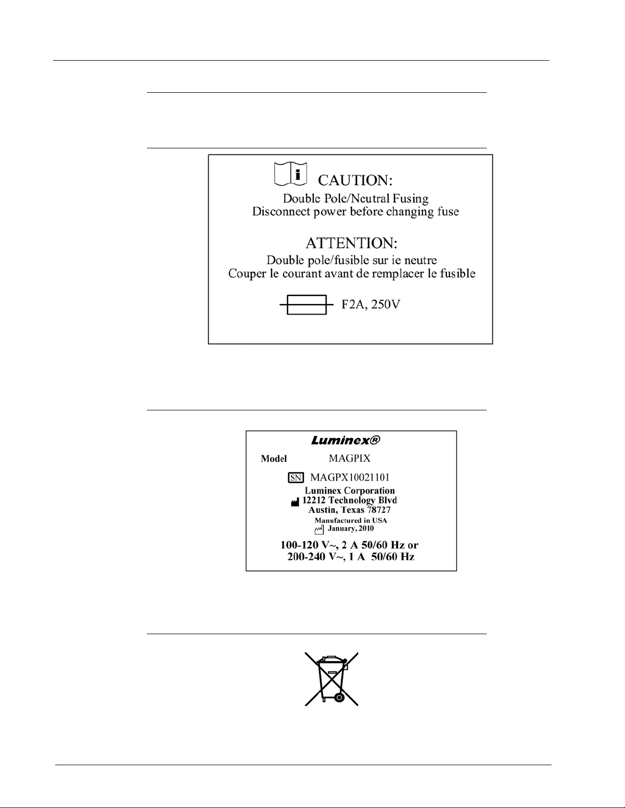
Regulatory Labels and Warnings
The following fuse caution label appears on MAGPIX.
FIGURE 1. Fuse Caution Label
A voltage label appears on the back of MAGPIX. It displays the MAGPIX serial number,
model number, power requirements, and manufacturer’s information.
FIGURE 2. Serial Number and Voltage Label
The WEEE (Waste Electrical and Electronic Equipment) label appears.
FIGURE 3. WEEE Symbol
4
Page 17
Safety and Regulatory Considerations
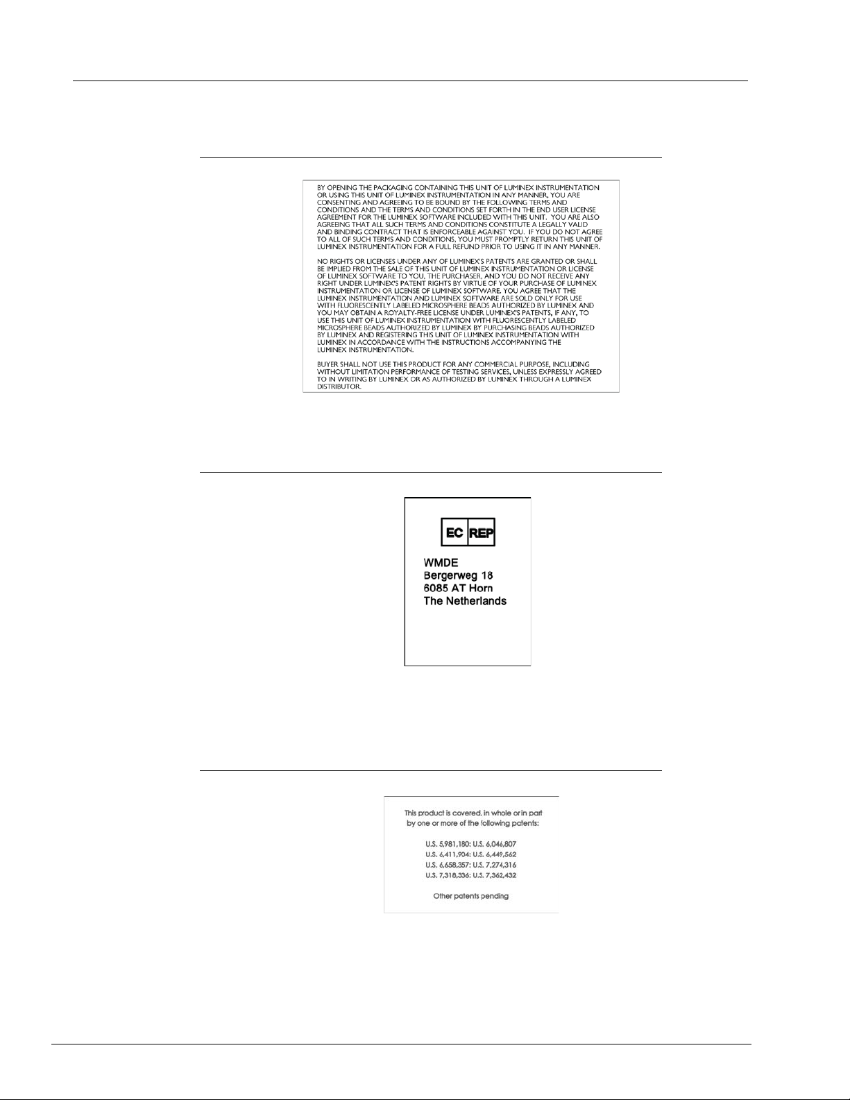
A label with legal information appears on MAGPIX.
FIGURE 4. Legal Information
Because MAGPIX complies with European Union safety requirements, it displays an EC
representative label.
FIGURE 5. EC Representative
Patient information appears on MAGPIX.
FIGURE 6. Patent
5
Page 18

Luminex IVD MAGPIX Hardware Installation and User Manual
E112918
Testing and Certifications
MAGPIX has been tested by MET and complies with safety requirements for the United
States and Canada.
FIGURE 7.
In addition, MAGPIX complies with European Union (EU) safety requirements and
therefore may be marketed in the Europe Single Market. The following European Union
compliance label appears on the back of the MAGPIX instrument.
FIGURE 8. European Union Compliance Label
MET Mark
6
Page 19
Safety and Regulatory Considerations
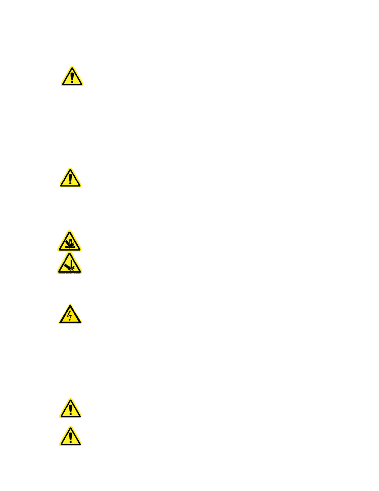
Safety Practices
In any situation in which you encounter this symbol, consult this manual or other Luminex
documentation to determine the nature of th e potentia l ha za rd and an y necessar y actio ns
you must take.
CAUTION: The protection provided by the equipment can be impaired or the
warranty voided if the Luminex MAGPIX system is used in a
manner not specified by the instructions or by Luminex
Corporation.
General
Keep the side access door closed and latched during normal operations.
DANGER: Do not, under any circumstances, remove the housing of the
instrument. Use of controls or adjustments or performance of
procedures other than those specified in Luminex MAGPIX
documentation can result in exposure to hazards.
Always observe standard laboratory
safety practices.
Mechanical
MAGPIX has parts that move during operation. Risk of personal injury is present. The
moving parts present puncture and pinching hazards. Keep your hands and fingers away
from the plate carrier slot, syringe pump, and sample probe during operation. The plate
carrier ejects without warning, especially during multiplate batches. Observe all warnings
and cautions. Keep the access door closed and latched during normal operations.
Electrical
Do not perform any maintenance or cleaning of the electrical components in the system,
with the exception of replacing fuses.
Observe the fuse caution stated on the fus e ca ut ion labe l. See “Fuse Caution Label” on
page 4. Be aware of the voltage of the instrument. See “Serial Number and Voltage Label”
on page 4.
Electromagnetic Compatibility
MAGPIX complies with the emission and immunity requirements described in IEC 613261 and IEC 61326-2-6. The electromagnetic environment should be evaluated prior to
operation.
WARNING: Do not use this instrument in close proximity to sources of strong
electromagnetic radiation, for example, unshielded intentio nal RF
sources, as these may interfere with the proper operation.
WARNING: Always handle MAGPIX according to Luminex instructions to
avoid any possible interference from its electromagnetic fields.
7
Page 20
Luminex IVD MAGPIX Hardware Installation and User Manual
Bar Code Reader Laser
The accessory bar code reader is classified under FDA 21 CFR 1040 .10 and 1040.11 as a
Class II laser product. In accordance with IEC 60825-1, the accessory bar code reader is
classified as Class 2.
The bar code reader laser presents a potential hazard to eyesight.
WARNING: Do not stare into the barcode reader beam or shine it into other
people’s eyes.
Heat
The heater plate, used to warm the plate carrier of the Y platfor m, can be heated between
35°C and 60°C.
CAUTION: Do not use the heater plate as an incubator. Its purpose is to
maintain the temperature of the microtiter pl ate while the plate is
in the MAGPIX instrument. Monitor the heater plate temperature
while it is in use. If it overheats, discontinue use and contact
Luminex Technical Support.
WARNING: The heater plate of the MAGPIX plate car rier may be ho t and can
cause personal injury if touched. Do not touch the heater plate.
Fluids
This instrument contains fluids. In the event of a fluid leak, turn off all power to the system
and disconnect all power cords. The on/off switch is not a method of disconnection; the
power cord must be removed from the outlet. Contact Luminex Technical Support for
further information.
DANGER: Do not operate the instrument in the presence of leaking fluid.
Monitor waste fluid levels periodically as a pre
container to overflow. Empty the waste fluid container each time you replace the Drive
Fluid container.
caution. Do not allow the waste fluid
Biohazard
Human and animal samples may contain biohazardous infectious agents. To avoid
pressurization problems, the waste fluid container is vented, so beware of biohazardous
aerosol material.
WARNING: Where exposure to potentially biohazardous material, including
aerosol, exists, follow appropriat e biosafety procedures and use
personal protective equipment (PPE). PPE includes gloves,
gowns, laboratory coats, face shields or mask and eye protection ,
respirators, and ventilation devices. Observe all local, state,
federal and country-specific biohazard handling regulations when
disposing of biohazardous waste material.
8
Page 21
Safety and Regulatory Considerations
Indicator Light
The lights inside the front panel of MAGPIX indicate the status of the system and are
harmless. The blue light-emitting diodes (LEDs) do not emit light in the UV spectrum.
Decontamination Procedure
Occasions may arise when it becomes necessary to decontaminate the entire MAGPIX
instrument. If you must decontaminate the instrument, sanitize the accessible surfaces
and the internal fluidics system. This is particularly import ant when bioh azardous samples
have been run.
WARNING: Wear appropriate personal protective equipment when handling
parts that come into contact with potentially biohazardous
samples.
To decontaminate MAGPIX:
1. Remov
household bleach solution diluted to 10% to 20% in water in the off-plate rea gent block
of the system.
2. Use
bleach solution followed by two wash commands with distilled water.
3. Emp
to 20% bleach solution followed by a distilled water rinse.
4. T
5. Clea
diluted to 10% to 20%.
6. Op
7. Clea
(10% to 20%).
e all specimens and all Luminex MAGPIX reagents. Leave distilled water and
the software to run a sanitize command with the diluted (10% to 20%) household
ty the off-plate reagent block and the waste container and clean each with a 10%
urn off MAGPIX and unplug the power cord.
n all exterior surfaces with mild detergent followed by a ho usehold ble ach solution
en the side access door of the instrument.
n all accessible surfaces with detergent followed by the household bleach solution
Disposal of Instrument
Within the European Union, the W aste Electrical and Electronic Equipm ent Directive 2002/
96/EC requires that you properly dispose of electrical and electronic equipment when it
reaches its end of life.
If you are disposing of a Luminex MAGPIX instr ume nt, decontaminate the system. See
“Decontamination Procedure” on page 9. Next, contact Luminex Technical Support for a
Return Material Authorization (RMA) num be r at +1-5 1 2-38 1- 4 39 7 (o ut sid e of th e U.S. ).
n the equipment to the following Luminex location:
Retur
Luminex Corporation
12201 Technology Blvd., Suite 130
Austin, Texas 78727, USA
For information about disposal of MAGPIX outside of the European Union, contact
uminex Technical Support at 1-877-785-2323 within the US and at +1-512-381-4397
L
outside of the US. For information about disposal of th e barcod e scann er , PC, or mon ito r,
refer to the manufacturer documentation.
9
Page 22

Luminex IVD MAGPIX Hardware Installation and User Manual
10
Page 23

CHAPTER 3 Installation Procedure
Before handling or unpacking MAGPIX, make certain th at the selected site is approp riate.
See “Installation Diagrams” on page 28 for handling and site installation requirements and
detailed dimensions of MAGPIX.
Check for these requirements:
• Indoors
• Operating temperature of 15-35°C (59-95°F)
• Operating relative humidity of 20-80%, noncondensing
• Operating altitude up to 2400m (7874 ft) above mean sea level
• Available electrical power outlet with protective earthing and easy accessibility
• Available area of approximately 3‘ X 3’ (91.44cm), including a 2” (5.08cm) clearance
between the back of MAGPIX and any wall or vertical surface.
• Stable, level surface
MAGPIX arrives in a large, corrug
FIGURE 9. The MAGPIX Overpack
ated cardboard overpack on skids.
CAUTION: This overpack is too heavy to be lifted by one person
(approximately 119lbs (53.97kg), a three-person lift) and should
be moved mechanically. Be careful the overpack is not punctur ed
during any necessary moving.
11
Page 24
Luminex IVD MAGPIX Hardware Installation and User Manual
1
2
3
4
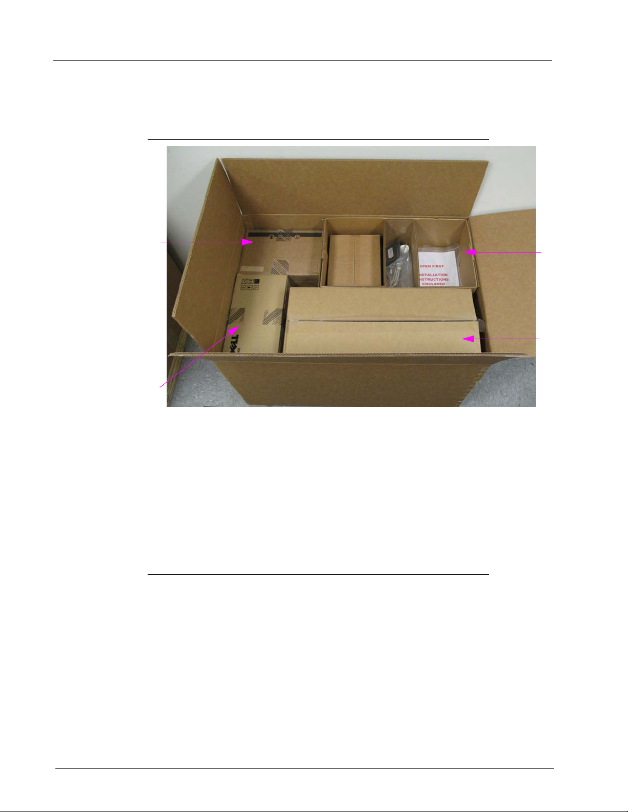
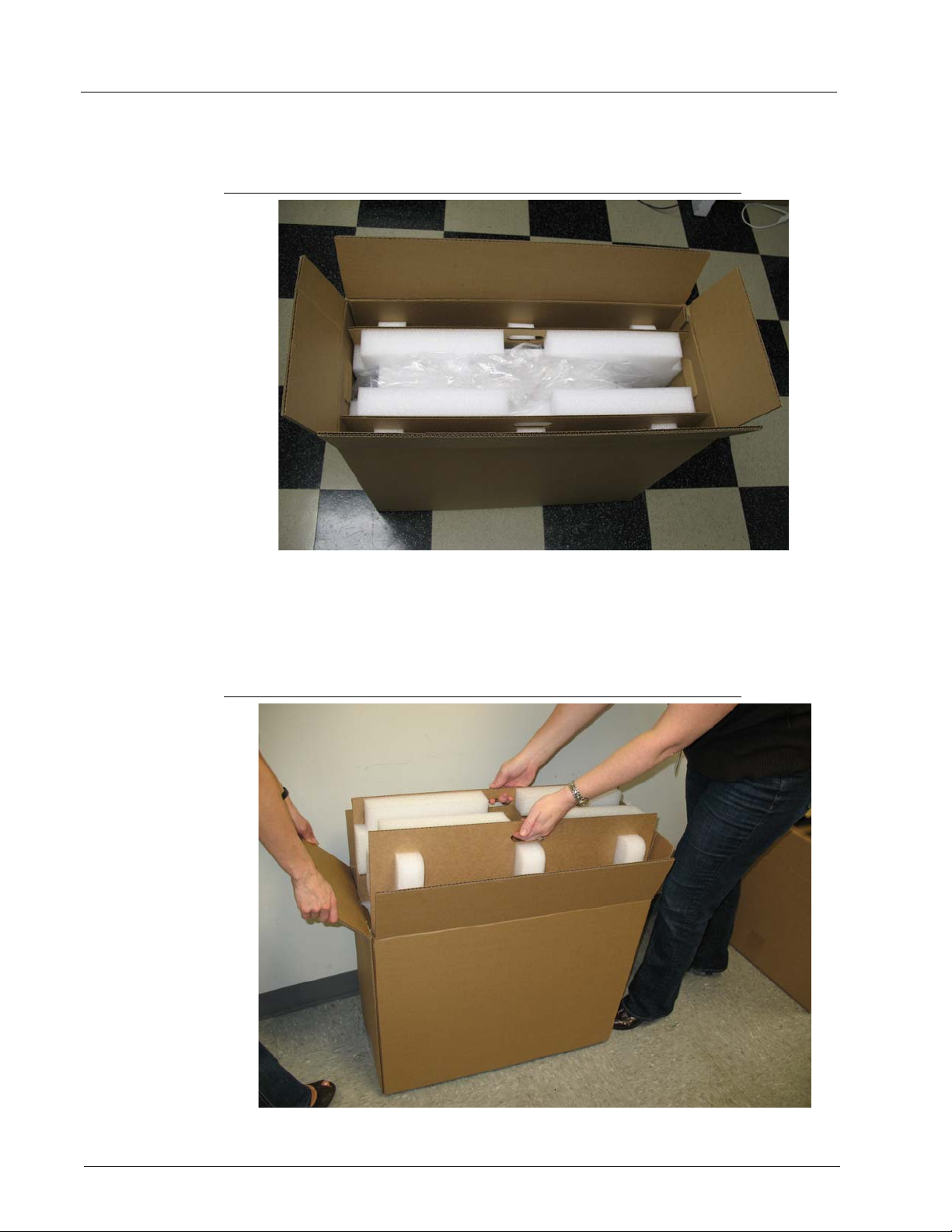
Within the overpack are separate cartons for the PC, the monitor, the 2-pack of Drive
Fluid, and the MAGPIX instrument. In addition, a divided tray contains the cables, CDs,
and printed material.
FIGURE 10. Inside the Overpack
1PC carton
2 Monitor carton
3 Accessory tray (monitor stand and Drive Fluid cartons are
underneath)
4 MAGPIX carton
Each individual carton can be handled by one person. The MAGPIX carton and the PC
carton each weigh less than 40 pounds (18.14 kg).
Unpacking and Assembling the PC
Begin the installation process with the PC. The computer and monitor are in the boxes at
the end of the overpack (See Figure 10.); the monitor stand is in a box underneath the
accessory tray.
The computer and monitor boxes include all the necessary cords and peripheral devices
well as complete installation instructions. Follow those instructions to set up the PC.
as
To set up the PC:
1. Remo
2. Asse
ve the three boxes containing PC components from the overpack.
mble the components using PC Installation Instructions or the instructions
provided by the PC vendor. Both are in the PC boxes.
12
Page 25
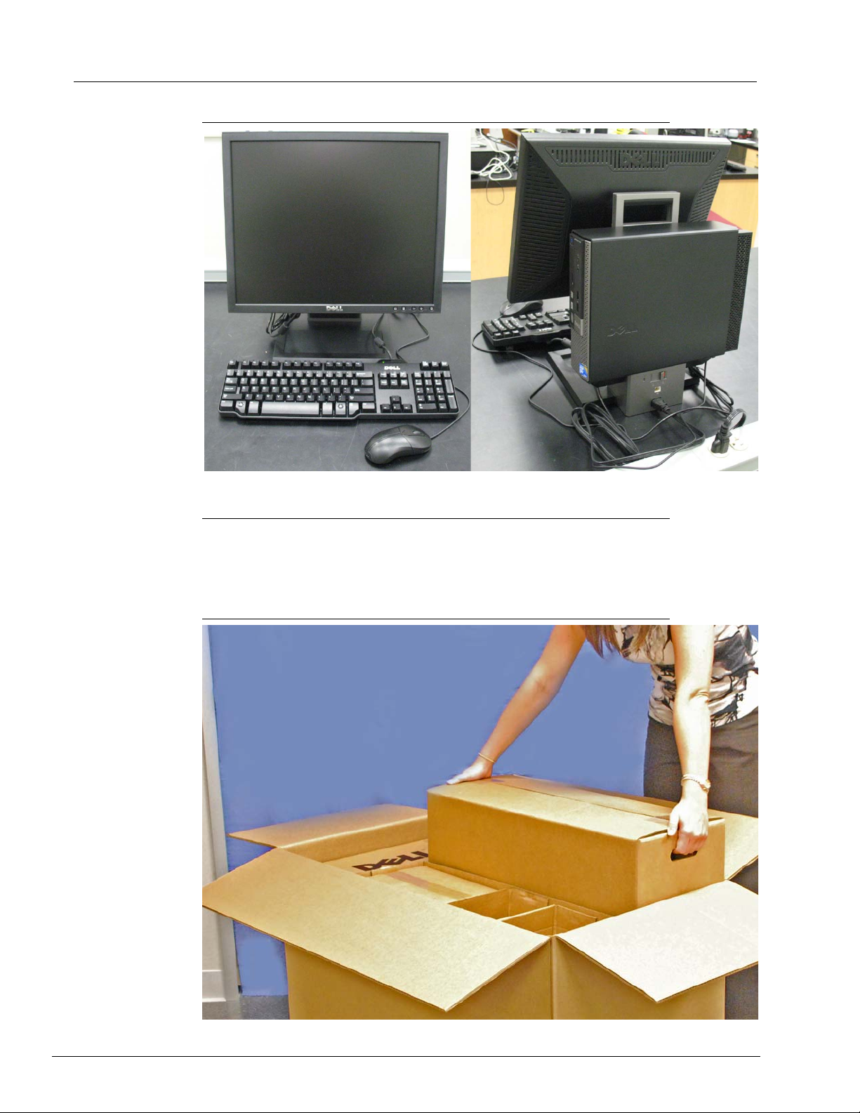
FIGURE 11. The Assembled PC
Installation Procedure
Unpacking and Assembling MAGPIX
To install the MAGPIX instrument:
1. Remo
ve the MAGPIX carton from the overpack.
FIGURE 12. Removing the MAGPIX Carton
13
Page 26
Luminex IVD MAGPIX Hardware Installation and User Manual
The MAGPIX instrument is inside a plastic bag and surrounded by foam inserts attached
to a corrugated cardboard insert.
FIGURE 13. The MAGPIX Carton, Opened
2. Remove MAGPIX from its carton by pulling on the handles that extend from the
cardboard insert.
NOTE: It
is helpful to have another person hold down the carton wh ile you
pull out MAGPIX.
FIGURE 14. Pulling MAGPIX from its Carton
14
3. Put the instrument on a stable, flat surface. This may require two people.
Page 27
4. Fold down the cardboard panels from each side of the instrument.
FIGURE 15. Removing the Packing Materials
Installation Procedure
5. Pull the plastic bag down from the top.
6. Place MAGPIX on
people.
Before proceeding with the installation, che
checklist on page 29 and make certain you can locate all listed items. Check contents to
make certain no damage h as occurred du ring shipp
contact Luminex Technical Support (in the U.S. and Canada, 1-877-785-BEAD
(-2323); outside of the U.S. and Canada, +1 512-381-4397; in Europe, +31 162 408 333).
to a lab bench or other flat, stable surface. This may require two
ck the contents of the overpack with the
ing. If anything is missing or damaged,
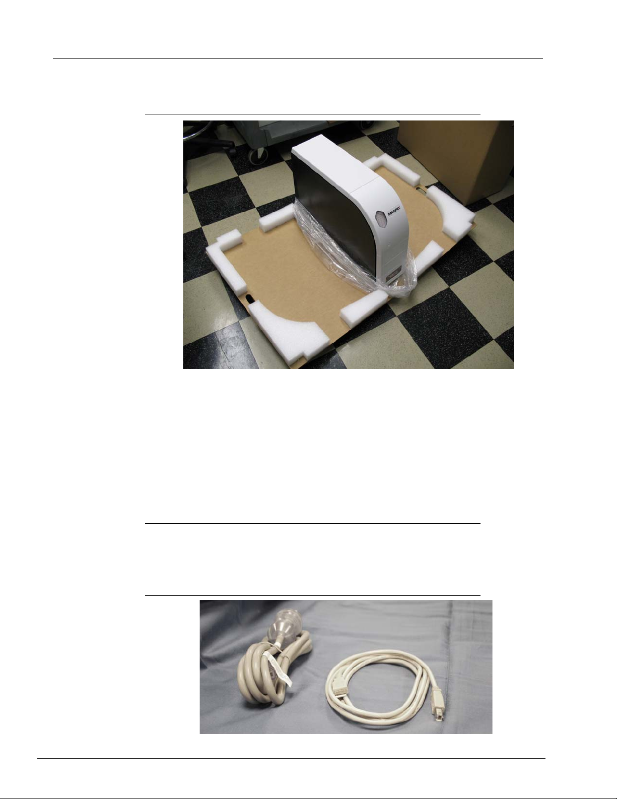
Connecting the Components
To connect the components:
ocate the cords in the accessory tray of the overpack.
1. L
FIGURE 16. Power Cord and USB Cable
15
Page 28

Luminex IVD MAGPIX Hardware Installation and User Manual
2. Plug the power cord into the back of the instrument.
3. Connect
the USB cable to the PC and to the connector labeled P1 on the back of
MAGPIX. Use the top right USB port on the PC.
FIGURE 17. Power Cord and USB Cable Connected
4. Connect the barcode scanner (if ordered) to the computer.
FIGURE 18. All Components Connected
16
Page 29

Installation Procedure
Preparing MAGPIX
Preparing MAGPIX includes removing the shipping plug, installing the Drive Fluid, and
installing the sample probe.
Removing the Shipping Plug
Inside the side access door of MAGPIX, a shipping plug holds the sample probe assembly
in place. Use the door access tool included in the accessory tray to open the side access
door and remove the plug.
CAUTION: MAGPIX should not be plugged into a power source when you
open this compartment.
To open the side access door and remove the shipping plug:
cate the door access tool in a small plastic bag in the accessory tray of the overp ack.
1. Lo
FIGURE 19. Door Access Tool
2. Insert the tool in the side access door latch and turn it one quarter turn clockwise.
FIGURE 20. Door Access Toll Inserted and Turned
3. Slide the door to the right.
17
Page 30

Luminex IVD MAGPIX Hardware Installation and User Manual
FIGURE 21. Sliding Open the Door
4. Raise the probe assembly and locate the shipping plug.
FIGURE 22. The Shipping Plug in Position
18
5. Pull the probe holder up, then, holding MAGPIX on the top with one hand to stabilize it,
firmly push the probe assembly away from you with your other hand. Be prepared to
use some strength.
Page 31

FIGURE 23. Pushing the Probe Assembly
6. With the probe assembly out of the way, lift out the shipping plug.
FIGURE 24. Lifting Out the Shipping Plug
Installation Procedure
19
Page 32

Luminex IVD MAGPIX Hardware Installation and User Manual
Installing the Sample Probe
MAGPIX comes with two sample probes, but the probe is not pre-installed.
To install the sample probe:
cate the sample probe, which is shipped in a tube in the accessory tray.
1. Lo
FIGURE 25. The Sample Probe and Its Container
2. Pull the probe assembly toward you and push it down.
3. Comp
letely unscrew the probe fitting on top of the probe holder by turning it
counterclockwise.
FIGURE 26. Unscrewing the Probe Fitting
20
4. Put the probe into the opening left by the probe fitting. It should slip down and catch at
the bottom of the opening.
Page 33

FIGURE 27. Inserting the Sample Probe
Installation Procedure
5. Reinstall the probe fitting, tightening it until it clicks into place.
FIGURE 28. The Sample Probe in Position
6. Close and latch the side access door.
21
Page 34

Luminex IVD MAGPIX Hardware Installation and User Manual
Installing the Drive Fluid
The overpack includes a carton contain ing two containers of Drive Fluid. Open the carton
and remove one container to install in the instr ument.
To install the Drive Fluid container:
cate the carton of Drive Fluid containers.
1. Lo
FIGURE 29. Drive Fluid Carton and Container
22
2. Open the carton and remove a container of Drive Fluid.
Page 35

3. Open the door of the fluid compartment on the front of MAGPIX.
FIGURE 30. The Fluid Compartment
Installation Procedure
4. Pull the Drive Fluid tube and plug in the left side of the fluid compartment forward until
it extends outside the compartment. Pu ll it to the left to allow room to insert the Drive
Fluid container.
FIGURE 31. Pulling out the Drive Fluid Tube and Plug
23
Page 36

Luminex IVD MAGPIX Hardware Installation and User Manual
5. Insert the Drive Fluid container part of the way into the fluid compartment opening and
remove the seal.
FIGURE 32. Removing the Seal
6. Connect the Drive Fluid tube and plug to the opening on the top of the Drive Fluid
container.
FIGURE 33. Connecting the Tube and Plug to the Container Opening
24
Page 37

Installation Procedure
7. Slide the container into the tray o n the lef t sid e of the fluid compartment. The container
tray is constructed to hold the container in place.
FIGURE 34. Sliding in the Drive Fluid Container
8. After the container is fully inserted, check the valve on the front of the waste fluid
container to make certain it is securely attached and close the door of the fluid
compartment.
Powering Up MAGPIX
MAGPIX has two on/off switches: a hard power switch and a soft power switch.
To power on MAGPIX:
1. Plug
2. T
the power cord from the back of the instrument into a power outlet.
NOTE: Lu
urn on the hard power switch. This is th e to ggle switch at the lower right corner of the
back of MAGPIX.
NOTE: T
minex recommends the use of a surge protector or UPS device
with MAGPIX. For more information, see “Uninterruptible Power
Supply (UPS) or Surge Protector” on page 44.
he hard power switch controls flow of power to the instrument.
25
Page 38

Luminex IVD MAGPIX Hardware Installation and User Manual
FIGURE 35. The Hard Power Switch
3. When you are ready to begin testing, turn on the soft power switch on the front of
MAGPIX. The blue LED in the hexagonal window lights up as confirmation that the
power is on. MAGPIX requires approximately 45 seconds to start up.
NOTE: The
soft power switch activates and deactivates the unit.
FIGURE 36. The Soft Power Switch
26
4. After MAGPIX is powered on, use the software to eject the tray carrier to put the off
plate reagent block in place.
Page 39

Installation Procedure
Performing an Initial Startup
Before using MAGPIX to analyze samples, perform an initial startup routine. All the
necessary procedures are described in the Luminex IVD xPONENT for MAGPI X Sof tware
User Manual and the Luminex xPONENT for MAGPIX Software Quick Guide.
To perform an initial startup:
1. From the Home page, select Probe and Heater, then perform a probe height
adjustment using a standard 96-well microtiter plate. If you use a plate with conical
wells, use one calibration sphere in the selected well. If you use a magwash or filter
plate, use two 5.08 mm discs stacked together in the selected well. Locate the sphere
and discs in the Probe Height Calibration Kit provided with the instrument.
2. After the probe has been calibrated, select the Cmds & Routines tab, then select
Revive After Storage from the routine drop down menu. Run Revive After Storage.
3. After the Revive Afte r S tor age routine is complete, select the Au to Maint tab and run
the Calibration/Verification procedure.
NOTE: Before running the calibration and verification procedure, be sure
to load the lot information on the CDs that are part of the
separately shipped Calibration and Verification Kits.
27
Page 40

Luminex IVD MAGPIX Hardware Installation and User Manual
Installation Diagrams
28
Page 41

Shipping Checklist
The MAGPIX overpack contains the following items:
Item Qty Part Number
MAGPIX Instrument 1 55-00022-00-002
PC 1 64-00087-00-001
Monitor 1 64-10049-00-001
All-in-One Monitor Stand 1 64-10050-00-001
Drive Fluid 2-pack 1 40-50014
Waste Bottle 1 CN-0261-01
Sample Probe 2 CN-0221-01
Power Cord 1 CN-P0XX-01
Installation Procedure
USB Cable 1 CN-0271-01
Side Access Door Tool 1 CN-0264-01
Sample Probe Height Adjustment Kit 1 CN-0263-01
Off-plate Reagent Block 1 CN-0260-01
xPONENT 4.1 Software for MAGPIX (DVD) 1 CN-SW20-01
Installing MAGPIX
xPONENT for MAGPIX IVD Quick Guide
IVD MAGPIX Installation and Hardware User Manual (CD) 1 CN-M082-01
IVD xPONENT for MAGPIX Software User Manual (CD) 1 CN-M084-01
PC Installation Instructions
96-wellplate Heater Block (optional) 1 CN-0224-01
Barcode reader (optional) 1 CN-PC03-01
1 89-30000-00-236
1 CN-M083-01
1 89-30000-00-263
NOTE: A MAGPIX Calibration Kit and a MAGPIX Performance
Verification Kit are shipped separately.
29
Page 42

Luminex IVD MAGPIX Hardware Installation and User Manual
30
Page 43

CHAPTER 4 Technical Overview
This chapter describes the operation, components, subsystems, and technical
specifications of MAGPIX.
How MAGPIX Operates
MAGPIX combines a fluidics system, a mechanical system, an electronic system and an
optical system with magnetic microspheres and complex computer analysis to perform
multiplex assays.
The mechanical system begins the process. An operator places a 96-well microtiter plate
on the plate carrier, which transports the plate into the instrument. The carrier moves
along the y axis, to allow the sample probe access to each column of the microtiter plate.
The sample probe assembly moves along the x and z axes, allowing it to access each row
of the microtiter plate. Between the y-axis movement of the carrier and the x-axis
movement of the sample probe, all wells of the microtiter plate are accessible.
The fluidics system handles the acquisition and transportation of the sample. The sample
probe descends into each well, drawing a sample for testing and drawing Drive Fluid from
the Drive Fluid container. The sample moves through the fluid tubing to the optics module,
transported by the Drive Fluid.
In the optics module, a magnet holds the magnetic microspheres in place while first a red
(classification) LED and then a green (reporter) LED illuminate them. They are imaged
during each illumination. After the images are recorded , the magnet withdraws, releasing
the microspheres for transport to the waste fluid container an d to clear the way for the next
sample.
xPONENT software analyzes the images, the red-illuminated images to classify the
microspheres and the green-illuminated images to determine what elements of the sample
have bonded to their surfaces. It reports the results to the operator.
31
Page 44

Luminex IVD MAGPIX Hardware Installation and User Manual
1
3
5
4
2
6
FIGURE 37.
MAGPIX Front & Right Side
1 Status indicator light
32
2 Soft on/off switch
3 Access door for plate carrier.
4 Access door for fluid compartment. For a more detailed illustration, see
Figure 46 on page 41.
5 Side access door
6 Side access door latch
Page 45

Technical Overview
1
2
3
FIGURE 38.
MAGPIX Back & Left Side
1 Communications port (P1)
2 Power input module
3 Rear air filter
33
Page 46

Luminex IVD MAGPIX Hardware Installation and User Manual
System Components
The following topics describe details of the three components of the Luminex MAGPIX
system: software, reagents, and hardware.
Software
Luminex xPONENT for MAGPIX software provides complete control of the MAGPIX
instrument and performs the analysis. The softwar e requires a dedicate d PC. For updated
information about the PC or operating system, see Luminex IVD xPONENT for MAGPIX
Software User Manual or access http://www.luminexcorp.com. Click the Support link to
open the FAQ list.
Under most circumstances, the PC that comes with the MAGPIX system is preloaded with
xPONENT for MAGPIX software. Luminex provides a software DVD to use if you need to
reinstall the software or need to inst all it on anothe r computer. If you install the software on
another PC, be sure that the PC meets the minimum specifications, including 4.0 GB of
RAM and a 2.66 GHz processor. The number of installations you can perform is limited by
your license.
The software DVD automatically installs the basic software only. To install the various
upgrades, contact Luminex Technical Support (1-877-785-2323 within the US and +1-512381-4397 outside of the US). A Technical Support representative can supply you with the
correct license number to install upgrades.
CAUTION: If you need to uninstall the software, follow carefully the procedure
provided by Luminex Technical Support.
The software is documented in two ways: in online help, which can be accessed from
within the application itself, and in PDF form, which is available on the Luminex website
and on a CD included with the shipped system.
CAUTION: Luminex recommends that you do not install additional software
on the PC that runs xPONENT for MAGPIX, with the exception of
Adobe Acrobat. Acrobat is required to view the PDFs and is
included on the installation CD. The operation of xPONENT for
MAGPIX has been validated only when it is the only program
running on the dedicated PC.
Hardware
The Luminex MAGPIX system includes the following hardware:
• The MAGPIX instrument
• Personal computer (PC) and necessary peripherals, including a monitor , keyboard and
mouse
• Power cable to connect MAGPIX to power outlet
• USB communication cable to connect MAGPIX to PC
• Two sample probes
• Sample probe height adjustment kit
• Off-plate reagent block
• Additional empty waste fluid container
34
Page 47

Technical Overview
• Side door access tool
• Barcode reader (optional)
• Heater block (optional)
The hardware is shipped with a quick insta llation guide , a quick so f tware user guide , a CD
co
ntaining both the software user manual and the hardware installation and user manual,
and a DVD containing the software.
Reagents
xMAP technology requires two kinds of reagents: common laboratory reagents and
reagents created especially for Luminex instruments.
CAUTION: Adhere to standard laboratory safety practices when handling
hazardous, toxic, or flammable reagents and chemicals. Contact
Luminex Technical Support when in doubt about compatibility of
cleaning and decontamination agents or materials.
Required Laboratory Reagents
• 10 - 20% household bleach solution
• 70% isopropanol or 70% ethanol solution
• 0.1N NaOH
• Sporicidin® Disinfectant
• Mild detergent
• Distilled water
WARNING: Isopropanol and ethanol are flammable liquids. Keep them away
from heat, open flames, and sparks in a well-ventilated area.
Remove them from the instrument when they are not in use.
xMAP Technology Reagents
• Drive Fluid (unit volume sufficient to run eight 96-well plates)
• MAGPIX Calibration Kit (to normalize the CL1 and CL2 classification channels and the
RP1 reporter channel parameters)
• MAGPIX Performance Verification Kit (to verify system integrity associated with the
CL1 and CL2 classification channels, the RP1 reporter channel, and the system
fluidics)
CAUTION: Protect MAGPIX calibration and verification reagents from light at
all times to avoid photobleaching of the microspheres.
WARNING: Luminex Drive Fluid contains ProClin
cause allergic reactions in some people. Additional information is
available in the Drive Fluid MSDS.
MAGPIX is shipped with a 2-pack of Drive Fluid. A MAGPIX Calibration Kit and a MAGPIX
Performance V erification Kit are shipped separately.
®
as a preservative. This can
35
Page 48

Luminex IVD MAGPIX Hardware Installation and User Manual
1
2
Subsystems
MAGPIX includes four subsystems: electronic, fluidic, mechanical and optical.
Electronic Subsystem
The electronics subsystem provides the power for operation and control of the MAGPIX
system and communication between its parts.
Power Input Module
The power input module contains the input power plug, hard power toggle switch, and
fuses. This is the protective earthing point for the MAGPIX system. The mating power cord
connector type is IEC-320-C13. The mating power cord provides electrical power to the
instrument when it is connected to an electrical outlet and is the means of disconnection.
The power input auto-senses the voltage range.
FIGURE 39. Power Input Module
1 Hard power toggle switch 2 Input power plug
WARNING: Do not obstruct this means of disconnection. Connect only to
outlets that contain protective earthing. Before changing a fuse,
turn off the instrument and unplug the power cord to avoid any
danger of electrical shock.
36
Page 49

Technical Overview
Communications Port
The communications port connects MAGPIX to the computer. It is a USB port, labeled P1.
FIGURE 40. Communications Port
Printed Circuit Board Assemblies
MAGPIX requires a series of printed circuit board assemblies (PCBAs), including four
major boards: optics control, XY controller, imaging, and processor. These PCBAs are all
contained within the same area as the optical system, are not accessible to the user, and
require no user maintenance.
Fluidics Subsystem
The fluidics subsystem handles the flow of liquid through MAGPIX. MAGPIX has two
doors that access its fluidics system: a side access door and a front door to the fluid
compartment.
Side Compartment and its Components
The side access door, at the upper front of the right side, provides access to the side
compartment, which contains the sample probe assembly, the sample valve, the tube
between the probe and the sample valve, the filter for the Drive Fluid, and the syringe
pump.
The side access door is secured with a latch th
CAUTION: Keep the side access door closed and latched during normal
operation. Unlatch it only to perform maintenance on the usermaintainable parts of the fluidics system.
at requires a door access tool to open.
37
Page 50

Luminex IVD MAGPIX Hardware Installation and User Manual
FIGURE 41. Side Access Door
FIGURE 42. Interior of Side Access Door
38
Page 51

Technical Overview
1
2
3
4
5
6
7
8
Syringe Pump and Drive Fluid Filter
The syringe pump draws fluid from the Drive Fluid cont ainer, in the bottom compartment of
the instrument. The fluid first passes through the Drive Fluid filter , which removes particles
greater than 35 microns in diameter.
The pumping action results from the up-and-down movement of the plunger guide in its
unting bracket, which moves the plunger up and down in the glass cylinder, drawing
mo
Drive Fluid in through the filter and into the valve and forcing it out into the sample loop.
FIGURE 43.
Syringe Pump and Drive Fluid Filter
1 Drive Fluid filter 5 Mounting bracket
2 Plunger 6 Plunger guide
3 Tube from Drive Fluid container 7 Syringe pump valve
4 Glass cylinder 8 Sample loop
WARNING: Avoid contact with moving parts.
39
Page 52

Luminex IVD MAGPIX Hardware Installation and User Manual
1
2
3
5
6
4
7
8
9
Sample Probe Assembly
The stainless steel sample probe fits inside a holder. A probe fitting screws into the top of
the holder, keeping the pro be in pla ce. Fro m the probe, thr ough the fitting, exten ds a tube
that passes through a strain relief and a ttaches to th e sample valve. The samp le loop from
the syringe pump also enters the sa mple value, an d a tu be extend s fr om it into the op tical
chamber, carrying the sample mixed with Drive Fluid.
A wheel pulley, covered by a protective shield, moves the probe assembly along the x
is.
ax
FIGURE 44. Sample Probe
Assembly
1 Sample loop 4 Valve-to-optical chamber
tube (coded red)
2 Strain relief 5 Sample probe 8 Probe holder
3 Probe-to-valve tube
(coded black)
6 Sample valve 9 Probe fitting
WARNING: Avoid contact with moving parts.
WARNING: Wear appropriate personal protective equipment when handling
7 Protective cover on
wheel pulley
parts that come into contact with potentially biohazardous
samples.
40
Page 53

Technical Overview
1
2
3
The Fluid Compartment
At the bottom of the front panel of MAGPIX, a door folds down to provide access to the
fluid compartment. Within that compartment, two trays hold the Drive Fluid and waste fluid
containers. Internal sensors monitor the fullness of the waste fluid container and the
emptiness of the Drive Fluid container. When either container reaches an unacceptable
level, MAGPIX stops. Luminex IVD xPONENT for MAGPIX Software User Manual
provides instructions for setting up an alert to warn you about unacceptable fluid levels.
FIGURE 45. Door to Fluid Compartment
The Drive Fluid container comes pre-filled and is disposable. The reusable waste fluid
container receives waste from the system . The waste and Drive F luid tubes connect to the
waste fluid and Drive Fluid containers using clear tubing.
WARNING: Wear appropriate personal protective equipment when handling
parts that come into contact with potentially biohazardous
samples. Make certain the waste fluid container is properly
vented.
FIGURE 46. Fluid Compartment, Interior
41
Page 54

Luminex IVD MAGPIX Hardware Installation and User Manual
1
2
1 Drive Fluid container in place
2
3 Valve attaching waste tubing to waste fluid container
Waste fluid container in place
Mechanical Subsystem
x-Axis and y-Axis Movement
The MAGPIX mechanical subsystem includes the plate carrier and the assembly that
moves the sample probe. The carrier moves along the y axis, to allow the sample probe
access to each row of the microtiter plate. The sample probe assembly mo ves along the x
and z axes, allowing it to access each column of the microtiter plate. Between the y-axis
movement of the carrier and the x-axis and z-axis movement of the sample probe, all wells
of the microtiter plate are accessible.
FIGURE 47. MAGPIX Plate Carrier Assembly
42
1 Microtiter plate area
2 Off plate reagent block area
Page 55

FIGURE 48. MAGPIX Sample Probe Assembly
1
2
Technical Overview
1 Pulley wheel that moves sample probe assembly along x-axis (cover removed)
2 Sample probe
Air Filters
MAGPIX has two air filters, one on the bottom of the instrument and one on the back of
the instrument. These filters require periodic cleaning to perform optimally.
The filter on the bottom of MAGPIX
instrument. This requires lifting up or tilting the instrument. The filter on the back of
MAGPIX can be slid up out of its holder.
CAUTION: Before lifting the instrument, remove all liquid from the off plate
reagent block and remove the fluid containers.
FIGURE 49. Bottom of MAGPIX showing filter in place in holder
can be slid out of its holder toward the front of the
43
Page 56

Luminex IVD MAGPIX Hardware Installation and User Manual
FIGURE 50. Back of MAGPIX showing filter in place in holder
Optical Subsystem
The MAGPIX optical subsystem consists of red and green LED illumination, a CCD-based
imager, an ima ging chamber, and a magnet to hold the magnetic microspheres in place
during the imaging process. The optical subsystem is contained in the same area as the
PCBAs. It is not accessible by the user and requires no user maintenance.
Recommended Additional Equipment
Successful operation of the Luminex MAGPIX system may require additional equipment.
Uninterruptible Power Supply (UPS) or Surge Protector
Luminex recommends using either an uninterruptible power supply (UPS) or a surge
protector to protect your system from power outages. Use a UPS that provides 585 Watts/
960 VA for at least 60 minutes. Select a surge protector that fits your requirements with
regard to electrical environment, endurance, suppressed voltage rating, and method of
protection. The surge protector requires three outlets and a minimum rating of 585 Watts.
Either piece of equipment should bear an appropriate safety certification mark for your
region, for example, Underwriters Laboratory (UL), Canadian Standards Association
(CSA), or Conformité Europeénne (CE).
44
Page 57

Technical Overview
Printer
Use a printer compatible with Microsoft® Windows XP Pro sp3.
Barcode Labels
Use Code 128 barcode label type when scanning barcode labels into the system.
Vortex
Use VWR product number 58816-12, with a speed range of 0 to 3200 rpm, or equivalent.
Bath Sonicator
Use Cole-Parmer® product number 08849-00, with an operating frequency of 55 kHz, or
equivalent.
System Specifications
General Specifications
• Start-up time: Under 15 minutes, including flushing system lines, system calibration,
and system verification
• System verification: 5 minutes
• Shutdown time: Under 15 minutes
• Time to complete one 96-well microtiter plate: Under 1 hour with 50 regions, 2000
microspheres per region per well, counting 50 microspheres in each region, aspirating
30 L out of a 75 L sample
• Physical Dimensions: 20.3 cm (8”) width, 66 cm (26”) depth, 43.2 cm (17”) height
• Weight: 40 lbs. (18.0 kg)
• Installation Category II
• Pollution degree 2
• Temperature control: maintains samples using the heater block at a constant
temperature from 35° C to 60° C (95° F to 131° F) +/- 1° C of setpoint.
• Automatic transfer of assay protocols and new reagent information into the system
using a large capacity read/write DVD
• Automatic sampling from a 96-well microtiter plate, beginning from any well position
• Automatic real-time analysis
• Analysis of multiple assay protocols per microtiter plate
• Barcode reader entry of sample IDs
• Produces sound pressure levels below 85 dBA
Environmental Conditions
• Indoor use only
• Operating temperature: 15-35°C (59-95°F)
• Operating relative humidity: 20-80%, noncondensing
45
Page 58

Luminex IVD MAGPIX Hardware Installation and User Manual
• Operating altitude: up to 2400m (7874 ft) above mean sea level
• Shipping temperature: 0-50°C (32-122°F)
• Storage temperature: 10-40°C (50-104°F)
Electronics
• USB 2.0-compatible communications link for fast data transfer
• Input voltage range: either 100-120 V~, 2.0 A 50/60 Hz or 200-240 V~, 1.0 A 50/60 Hz
Optics
• Reporter channel detection: A/D resolution 16 bits
• Reporter detector: CCD, detection bandwidth of 566 to 614 nm
• Classification detector: CCD
• Limit of Detection (LOD): For the reporter channel, using a blank microsphere from
region 078, 700 molecules of phycoerythrin (PE) per microsphere
• Dynamic Range: For the reporter channel, using a microsphere from region 078, 3.0
decades
• Efficiency: Classification Channels: 80%
Fluidics
• Sample load rate: 20 L to 500 L per second
• Sample uptake volume: 20 to 200 L
• Well-to-well carryover: < 4%
• Sample uptake accuracy: +/- 5%
Microtiter Plates
• Microtiter plate must be 96-well, not to exceed 1” (2.54cm) in height, including heater
block.
• Microtiter plate must be compatible with the microtiter heater block temperature when
the heater block is in use.
• All microtiter plates have standard width (85.5mm) and length (127.9 mm). Depth
varies depending on the type of well. Maximum allowable depth is 1” (2.54cm). Plates
must have minimum 0.06” (1.5mm) lip height, st andard distance from well center to
well center (9mm) and standard distance from A1 center to plate center in both length
and width. To be compatible in size with the microtiter heater block, the plate must fit
into the heater block so that the top is flush with the heater block.
Microspheres
• Distinguishes 1 to 50 unique MagPlex microspheres in a single sample
• Misclassification Rate 2%
• Classification Rate 80%
• Detects and distinguishes surface reporter fluorescence emissions at 590 nm +/- 24
nm on the surface of 1 to 50 unique MagPlex microsphere in a single sample
• Soluble background fluoresc en ce emis sio n at 590 nm +/- 24 nm au tom a tica lly
subtracted from fluorescence intensity values
46
Page 59

CHAPTER 5 Operational and
Maintenance Procedures
To ensure accurate test results, prope rly clean and maintain MAGPIX. Read and follow all
instructions in this chapter. To facilitate your maintenance process, print out and use the
maintenance logs on page 58.
General Maintenance Precautions
Observe the following general maintenanc e pr ecautions, which were explained in more
detail in the previous chapters:
• Personnel who use, maintain, or clean MAGPIX should be trained in standard
laboratory safety practices and should follow those practices when handling the
instrument.
• Samples and waste fluid can contain biohazardous material. Where exposure to
biohazardous material, including in a n aerosol form, exists, follow a ppropriate biosafety
procedures, use personal protec tive equi p men t, an d us e ven tila tio n devic es.
• Avoid contact with moving parts. Disconnect the instrument from the power source
when the procedure instructs you to do so.
• Do not remove the cover of MAGPIX. All maintenance can be performed from the
outside of the instrument, within the fluid compartment, or within the compartment that
is accessible by opening the side access door.
47
Page 60

Luminex IVD MAGPIX Hardware Installation and User Manual
Accessing the Side Compartment
The side compartment of MAGPIX contains the majority of user-maintainable
components. The access door to this compartment must remain latched during operation
of the instrument. Opening the access door requires a special tool provided with the
MAGPIX system.
FIGURE 51. Side Access Door Latch
To open the latch:
urn off and unplug MAGPIX.
1. T
2. Insert
3. Slide
the latch tool into the slot of the latch and turn it clockwise.
the door to the right.
Daily Procedures
Most of the daily maintenance tasks for MAGPIX can be performed using available
software commands. For details about performing these commands, refer to the IVD
xPONENT for MAGPIX Software User Manual or online help.
Initializing MAGPIX
Initialize MAGPIX at the start of each day using the xPONENT for MAGPIX software.
Refer to the IVD xPONENT for MAGPIX Software User Manual or online help. Initialization
requires less than five minutes and includes a quick system self-check.
Verifying MAGPIX
Perform verification using the xPONENT for MAGPIX software. Refer to the IVD
xPONENT for MAGPIX Software User Manual or online help.
48
Page 61

Operational and Maintenance Procedures
Maintaining Fluids
MAGPIX has a built-in compartment to hold a single-use disposable Drive Fluid container
and a reusable waste fluid container. It comes with two waste fluid containers and a twopack of Drive Fluid containers. All fluid tubing is contained within the instrument.
Monitor fluid levels daily. Replace the empty Dr
operates with an empty Drive Fluid container, the lack of Drive Fluid may interrupt a
sample and prevent further samples from being collected.
ive Fluid container as needed. If MAGPIX
CAUTION: Use only xMAP Drive Fluid. Use of any other Drive Fluid
constitutes improper use and can void the warranty provided by
Luminex, its authorized partner, or both.
Empty the waste fluid container whenever it
is full. Use the following guidelines:
• Replace the newly emptied waste fluid container with the second, dry waste fluid
container so the moisture remaining in the first waste fluid container does not trigger a
“waste bottle full” message.
• Before removing the waste fluid container, make certain all other fittings and tubes are
firmly attached to avoid any contamination from dripping waste fluid.
To empty the waste fluid container:
en the fluid compartment at the bottom front of MAGPIX.
1. Op
2. Disco
3. Car
4. Unscrew the cap
nnect the orange waste fluid line from the waste fluid container.
efully remove the waste fluid container from its tray.
on top of the waste fluid container to drain out the fluid.
NOTE: Disc
ard the waste fluid in accord with all local, state, federal, and
country-specific biohazard handling regulations.
5. Inser
t the second, dry waste fluid container in the fluid compartment.
WARNING: Waste fluid can contain biohazardous infectious agents. Where
exposure to potentially biohazardous materials (including aerosol)
exists, follow appropriate biosafety procedures and use personal
protective equipment such as gloves, gowns, laboratory coats,
face shields (or mask and eye protection), respirators, and
ventilation devices.
Shutting Down MAGPIX
Like initialization, shutdown is a standardized procedure in xPONENT for MAGPIX
software. It includes sanitize, wash, and soak routines. Refer to the IVD xPONENT for
MAGPIX Software User Manual or online help for instructions to perform shutdown.
49
Page 62

Luminex IVD MAGPIX Hardware Installation and User Manual
1
3
2
Weekly Procedures
Cleaning MAGPIX
Clean MAGPIX weekly using a 0.1N sodium hydroxide (NaOH) solution. Refer to the
software manual for instructions for running the Clean command.
Cleaning the Sample Probe
WARNING: Avoid contact with moving parts. If a plate is running, use the
software to execute Stop to avoid the possibility of exposure to
moving parts. MAGPIX must not be performing any operations
while you carry out this maintenance procedure.
To clean the sample probe:
1. Execute ST
2. Turn off MAGPIX and unplug the power cord.
emove the sample probe.
3. R
OP if a plate is running. Refer to the software manual for instructions.
• Open the side access door of MAGPIX.
• Unscrew the probe fitting on top of the probe completely.
• Grasp the probe gently and push up.
• Lift the probe out of the top of the probe holder.
FIGURE 52.
Probe Assembly
50
1 Probe fitting (Unscrew and remove in step 3.)
2 Probe holder
3 Probe - Push up gently and lift out of holder.
Page 63

Operational and Maintenance Procedures
4. Clean the sample probe using either a bath sonicator or a 10 mL syringe. If you are
using a bath sonicator , place the tip of the sample probe in the bath sonicator for 2 to 5
minutes. If you are using a syringe, force distilled water through the tip of the sample
probe to its large end. This dislodges any debris clogging the tip.
5. Rep
6. Use
lace the sample probe and tightly screw in the probe fitting.
the software to perform an automatic probe heig ht adjustment.
NOTE: Perform an automatic probe height adjustment an y time the probe
is reinstalled after removal.
Performing a Visual Inspection
Inspect MAGPIX weekly. Make sure the instrument is idle, so there are no moving parts.
Open the MAGPIX side access door and fluid compartment door and visually inspect for
leaks, corrosion, and other signs of improper function. Check all visible tubing
connections.
Calibrating and Verifying MAGPIX
Calibration, with a follow-up verification, is another weekly procedure that can be
performed using the xPONENT for MAGPIX software. Refer to the Luminex IVD
xPONENT for MAGPIX Software User Manual or online help for instructions.
Removing Clogs
If you frequently use MAGPIX to test concentrated serum or other debris-ridden samples,
Luminex recommends that you perform a clog removal routine weekly. Otherwise, you can
perform this procedure as needed. See Luminex IVD xPONENT for MAGPIX Software
User Manual for instructions. Run the alcohol flush command, substituting sodium
hydroxide (NaOH) for alcohol.
To remove clogs:
1. Rep
2. Ru
lace the alcohol in the alcohol well of the off-plate reagent block with a 0.1N
sodium hydroxide solution.
n the alcohol flush command.
WARNING: Sodium hydroxide is extremely caustic. If it comes into contact
with skin, it can burn and cause tissue damage without causing
pain. Always wear gloves and goggles when working with sodium
hydroxide.
51
Page 64

Luminex IVD MAGPIX Hardware Installation and User Manual
Monthly Procedures
Clean the exterior surfaces monthly.
To clean exterior surfaces:
urn off MAGPIX and unplug the power cord.
1. T
2. Clea
3. Op
4. Clea
n all exterior surfaces with mild detergent, followed by a household bleach solution
diluted to 10% to 20%, followed by distilled water.
en the side access door of the instrument.
n all accessible surfaces with detergent, followed by the household bleach solution
(10% to 20%), followed by distilled water .
WARNING: Avoid contact with the tubing and electronic parts of the
instrument.
5. Dry any unpainted metal surfaces to prevent corrosion.
6. Plug
in the power cord and turn on MAGPIX.
Semi-Annual Procedures
Maintaining Air Filters
MAGPIX has two air filters, one on the bottom of the instrument and one on the back of
the instrument. Every six months, remove these air filters, clean them, and reinstall them.
To clean MAGPIX air filters:
1. T
urn off MAGPIX and unplug the power cord.
2. Slide
3. Lif
4. Clean the filters
5.
the back filter up out of its holder.
t MAGPIX and slide the bottom filter out of its holder toward the front of the
instrument.
CAUTION: Before removing the bottom air filter, remove both the waste fluid
and Drive Fluid containers, the off-plate reagent block, and any
microtiter plates in the instrument.
with a vacuum or with distilled water. Stand the filters upright to air dry.
CAUTION: Filters must be completely dry prior to reinstallation.
Locate the small incised arrow on the frame of the filter. This indicates air flow. The
filter must be installed with th
FIGURE 53. Arrow on Air Filter Frame
e arrow pointing inward.
52
6. Reinstall filters.
7. Plug
in the power cord and turn on MAGPIX.
Page 65

Operational and Maintenance Procedures
After
Before
FIGURE 54. Bottom of MAGPIX, Filter holder
FIGURE 55.
Back of MAGPIX, before and after removal of filter
53
Page 66

Luminex IVD MAGPIX Hardware Installation and User Manual
1
2
3
4
5
Replacing the Syringe Seal
When you replace a syringe seal, also replace the black O-ring that fits inside it. One
package contains four of each.
urn off MAGPIX and unplug the power cord.
1. T
WARNING: The plunger guide does NOT deactivate while the seal is being
changed; unplugging is necessary to avoid injury.
2. Open the side access door of MAGPIX.
cate the syringe (glass cylinder with a metal rod plunger).
3. Lo
4. Push the
plunger guide down. The syringe may fill with clean Drive Fluid.
NOTE: T
he plunger guide is tight. Be prepared to use some force to push
it down.
5. Unscrew the syr
6. Pull
7. Usi
the plunger out of the syringe and dispose of any Drive Fluid.
ng a pair of pliers, remove the white plunger seal (at the top of the plunger) and
inge from the top of its housing and carefully remove it.
discard it.
8. Place the
black O-ring inside the new white plunger seal and press the seal down on
the top of the plunger.
9. Retur
10.Scr
n the plunger to the syringe.
ew the syringe back into its housing.
FIGURE 56.
The Syringe
54
1 Syringe housing 3 Syringe seal, containing
2 Metal rod plunger 5 Plunger guide
black O-ring
4 Glass cylinder
11.Return the plunger guide to its original position. The bottom of the plunger fits into the
indentation in the plunger guide.
ug in the power cord and turn on MAGPIX.
12.Pl
13.Use the
software to run the prime command twice, watching for any leaks in the
syringe area.
se the side access door.
14.Clo
Page 67

Operational and Maintenance Procedures
1
2
3
4
5
1
2
3
Annual Procedures
Replacing the Sample Probe Tube
The tube that connects the sample probe to the valve is subject to wear because of the
constant motion of the sample probe. Conseq uently, maintenance requir es repl acing it o n
a yearly basis.
FIGURE 57. Sample Probe Tube
1 Sample probe tube (color-coded black at valve end)
2 Valve
FIGURE 58. Sample Probe Tube Assembly
1 1/4-28 Flat-bottom fitting 2 Tube between probe and valve 3 Probe fitting
3 1/4-28 flat-bottom fittings
4 Strain relief
5 Probe fitting
55
Page 68

Luminex IVD MAGPIX Hardware Installation and User Manual
1
2
3
4
To replace the sample probe tube:
urn off MAGPIX and unplug the power cord.
1. T
en the side access door on MAGPIX and locate the probe assembly.
2. Op
3. Unscrew the pr
4. Unscrew the 1/4
obe fitting completely. The sample probe tube is connected to it.
-28 flat-bottom fitting at the valve end of the sample probe tube. The
sample probe tube is connected to it. Use pliers to disconnect the 1/4-28 flat-bottom
fitting if necessary .
5. Pull the
6. Th
7. Scr
loose tube through the strain relief to remove it.
read the new piece of tube through the strain relief.
ew the 1/4-28 flat-bottom fitting on the end of the new sample probe assembly into
the valve where you removed the fitting during step 4.
8. Scre
w the probe fitting on the end of the new sample probe asse mbly into the top of the
probe assembly where you removed the probe fitting during step 3.
Replacing the Drive Fluid Filter
To replace the Drive Fluid filter on MAGPIX:
urn off MAGPIX and unplug the power cord.
1. T
en the side access door on MAGPIX and locate the Drive Fluid filter at the lef t of the
2. Op
syringe pump.
ntly pull the filter from the mounting bracket.
3. Ge
4. Unscrew the tub
attach the tubing to the ends of the new filter.
5. Re
ss the new filter into the mounting bracket. Be sure the filter is or iented the way it is
6. Pre
in the following picture.
ing from the top and bottom of the filter.
FIGURE 59.
7. Close the side access door.
8. Plug
9. Use
in the power cord and turn on MAGPIX.
the software to run the prime command twice.
Drive Fluid Filter
1 & 3 Tube attachments (Unscrew in step 3)
2Filter
4 Mounting bracket
56
Page 69

Operational and Maintenance Procedures
1
As Needed Maintenance
Replacing Fuses
Periodically, you may need to replace a fuse on MAGPIX. Use fuses with the following
specifications:
• F2A, 250 V
The fuse cartridge will accept either 5 mm x 20 mm or 0.25” x
available from Luminex Corporation. Re pla cin g a fus e re qu ire s ac ces s to the ba ck of
MAGPIX.
1.25” fuses. Fuses are
DANGER: To avoid serious injury or death by electric shock, turn off
MAGPIX and unplug it from the wall before replacing a fuse.
To replace a fuse:
1. Unp
2. Use
3. Use
lug the power cable from the instrument.
a small, flat blade screwdriver to open the power module door on the lower right
corner of the back of the instrument. The door opens downward. Inside is a red
cartridge.
the screwdriver to remove the cartridge.
FIGURE 60. Power Module
1 Insertion point for screwdriver blade
4. Check both of the fuses in the cartridge for damage. A fuse can display physical
evidence of damage, for example, broken wire or blackened glass; if it displays no
physical evidence, test it for continuity with a voltmeter.
5. Rep
6. Rep
7. Shu
8. Plug
lace any damaged fuse with the correct type of fuse.
lace the cartridge.
t the module door.
in the power cord and turn on MAGPIX.
57
Page 70

Luminex IVD MAGPIX Hardware Installation and User Manual
Maintenance Logs
Reproduce the following forms as necessary and use them to record maintenance
information. Fill in the dates in the first line of the table. The first table includes a sufficient
number of columns for one week (7 days). The second table includes a sufficient number
of columns for monthly maintenance (one task monthly), semi-annual maintenance (two
tasks twice yearly), and annual maintenance (two t asks yearly). For each item listed at the
left, enter your initials under each date on which you perform the task.
Short Term Maintenance - One Week
Date
Daily Maintenance
Initialize with alcohol flush
Verify
Check fluid levels
Shut down with sanitize
Weekly Maintenance
Clean MAGPIX
Clean probe
Calibrate and Verify
Perform visual inspection
Remove clogs (if necessary)
58
Page 71

Operational and Maintenance Procedures
Long Term Maintenance - One Year
Date
Monthly
Maintenance
Clean exterior
surfaces
Semiannual
Maintenance
Clean air filter
Replace syringe
seal
Annual
Maintenance
Replace Drive
Fluid filter
Replace sample
probe tube
59
Page 72

Luminex IVD MAGPIX Hardware Installation and User Manual
60
Page 73

CHAPTER 6 Troubleshooting Procedures
Troubleshooting procedur es help users iden tify and remedy p roblems with the instr ument.
Overview
To troubleshoot a problem, locate the problem in one of the sections in this chapter,
explore the possible causes, and take the described corrective action.
This chapter supplies information about the following topics:
• Power Supply Problems
• Communication Problems
• Clogs
• Fluid Leaks
• Sample Probe Problems
• Calibration Slowness and Failure
• Verification Slowness and Failure
• Acquisition Slowness and Failure
• Carryover Problems
• Bead Detail Irregularities
Contact Luminex Technical Support in the U.S. and Canada by calling 1-877-785-BEAD
(-2323). Outside of the U.S. and Canada, call +1 512-381-4397. Contact Luminex
Technical Support in Europe by calling +31 162 408 333. Email inquiries to
support@luminexcorp.com.
Additional information is available on the Luminex website. Search the desired topic or
navigate through menus. Also, review the website’s FAQ section. Enter http://
www.luminexcorp.com in your browser’s address field. Click Support>Support Login to
log into the Support FAQ site.
This chapter does not troubleshoot problems with the PC. For help with PC problems,
please contact the technical support department for the manufacturer of your PC.
61
Page 74

Luminex IVD MAGPIX Hardware Installation and User Manual
Power Supply Problems
Power supply problems often involve a blown fuse, faulty electronic component, or
disconnected cable.
CAUTION: Whenever you deal with a potential electrical problem, be careful
to avoid electrical shocks.
TABLE 2.
Problem Possible Cause Corrective Action
MAGPIX will not turn
on.
Fuses continue to open
(blow).
The power cord is
disconnected.
The hard power switch
on the back of the
instrument is not turned
on.
No voltage is coming
from the electrical
outlet.
The power supply is
faulty.
A fuse has burned out. See “Replacing Fuses” on
A component has a
short circuit.
Plug in the power cord.
Turn on the switch.
Change to a different outlet. If
MAGPIX is plugged into a surge
protector, make certain the surge
protector is turned on.
Contact Technical Support.
page 57.
Contact Technical Support.
Communication Problems
Communication problems described in this section involve the links between the data
system (PC and software) and MAGPIX. “Communication” refers to the transfer of data
between the PC and MAGPIX, including the current status of the instrument, instrument
control, sample acquisition, session uploading, and start, stop, and pause features.
TABLE 3.
Problem Possible Cause Corrective Action
The PC cannot
establish
communication with
MAGPIX.
The communication
cable is unplugged or
plugged into the wrong
port.
MAGPIX is not turned
on.
Plug in or move the
communications cable.
Turn off the PC. Turn on
MAGPIX and then turn on the
PC.
62
Page 75

Troubleshooting Procedures
Clogs
Often, a clog somewhere in MAGPIX is the cause of a problem with calibration,
verification, or data acquisition. To determine whether there is a clog, run performance
verification to see if the fluidics functio n is operating properly. In the event you encounter a
problem that is clog-related, use the following procedure.
To troubleshoot a possible clog:
1. Clean and adjust the sample probe. See “Cleaning the Sample Probe” on page 50.
2. Perform the procedure for removing clogs. See “Removing Clogs” on page 51.
3. Run calibration and verification.
If this procedure is unsuccessful, call Luminex Technical Support.
Fluid Leaks
There are numerous places in MAGPIX where fluid can leak. Most leaks can be easily
fixed; for the remainder, call Technical Support.
TABLE 4.
Problem Possible Cause Corrective Action
Fluid is pooled around
MAGPIX.
Fluid leaks within the instrument:
A fluid tube leaks. The tube is damaged. If it is the sample probe tube,
The waste bottle leaks. The waste bottle fitting
The Drive Fluid filter
leaks.
The sample probe
leaks.
The sample valve leaks. The sample valve has
Fittings, fluid tubes, or
components are
damaged, loose, or
faulty.
is loose.
Drive Fluid filter fittings
are loose.
The sample probe is
clogged.
The sample probe fitting
is loose.
one or more loose
fittings.
The sample valve is
faulty.
Turn off and disconnect the
instrument to avoid electrical
shock. Check for possible
sources of Ieaking and correct
them. If leaking continues,
contact Technical Support.
replace it. See “Replacing the
Sample Probe Tube” on page 55.
Otherwise, contact Technical
Support.
Reset the waste bottle fitting.
Hand tighten the Drive Fluid filter
fittings.
See “Clogs” on page 63.
Tighten the fitting.
Hand tighten the sample valve
fittings.
Contact Technical Support.
63
Page 76

Luminex IVD MAGPIX Hardware Installation and User Manual
TABLE 4.
Problem Possible Cause Corrective Action
The syringe seal leaks. The seal is worn out or
faulty.
The syringe valve leaks. The valve is loose or
faulty.
Sample Probe Problems
Problems with the sample probe can lead to both fluid leaks and acquisition failure.
TABLE 5.
Problem Possible Cause Corrective Action
The sample probe
leaks.
The sample arm is
stuck in the up or down
position.
The sample arm does
not go down smoothly.
The sample probe
motor connections are
loose.
The sample probe
motor is faulty.
The microtiter plate is
incorrectly seated.
The microtiter plate is
warped.
The sample probe is
bent.
Replace the syringe seal. See
“Replacing the Syringe Seal” on
page 54.
Hand-tighten the syringe
connection (silver knob) on the
syringe valve. Run a Prime
command. If leaking continues,
contact Technical Support.
See “Fluid Leaks” on page 63.
Contact Technical Support.
Contact Technical Support.
Adjust the microtiter plate.
Replace the microtiter plate.
Remove the sample probe from
the instrument and roll it on a flat
surface to straighten. If a sample
probe has been bent and rolled
straight more than once, discard
it and replace it with a new
sample probe. Perform an
automatic sample probe height
adjustment using the software.
64
Page 77

Troubleshooting Procedures
Calibration Slowness and Failure
Calibration problems can result from a variety of causes, many of them easily correctable
human errors.
TABLE 6.
Possible Cause Corrective Action
Possible Calibration Microsphere Causes:
The calibration microspheres are not fully
resuspended.
The wrong lot number or target values
were entered in the software.
The calibration microspheres are in the
wrong well.
There are not enough calibration
microspheres in the well.
You are using the incorrect calibration
microspheres.
The calibration microsphere lot is expired. Substitute an unexpired bottle of calibrator
Possible Sample Probe Causes:
The sample probe height is incorrect. Perform an automatic sample probe
The sample probe is clogged. See “Clogs” on page 63.
The probe fitting is loose. Tighten the probe fitting.
Other Possible Causes:
There is a partial clog in the instrument. See “Clogs” on page 63.
There is air in the instrument. Perform an automatic sample probe
The sample valve is faulty. Contact Technical Support.
There is a problem internal to the
instrument.
No events are being collected during
calibration.
Vortex the calibration vials to resuspend
the microspheres.
Correct the lot number and target values
in the software.
Change the well setting in the software.
Add at least five drops of calibration
microspheres to the well. For accurate
drop volume, hold the vial upside down at
a 90 degree angle to the microtiter plate
while dispensing them.
Use the xMAP MAGPIX Calibration Kit.
microspheres.
height adjustment.
height adjustment. Use the software to run
a prime command three times, an alcohol
flush command twice, then a wash
command three times with distilled water.
Make sure the Drive Fluid coil is not
pinched.
Review the log of calibration reports.
Check for dramatic changes in
temperature or voltage. If any of these are
present, contact Technical Support.
Check the drive and waste fluid levels.
Verify that tubing for both containers is
tightly connected.
Check for sample probe problems.
65
Page 78

Luminex IVD MAGPIX Hardware Installation and User Manual
Verification Slowness and Failure
Like calibration problems, verification problems can have a variety of causes.
TABLE 7. Verification Slowness and Failure
Possible Cause Corrective Action
Possible Verification Microsphere Causes:
The verification microspheres are not fully
suspended.
The wrong lot number or target values
were entered in the software.
The instrument verification microspheres
are in the wrong well.
There are not enough verification
microspheres in the well.
You are using the incorrect verification
microspheres.
The verification lot is expired. Use an unexpired bottle of verification
The verification microspheres have been
diluted.
Possible Sample Probe Causes:
The sample probe height is incorrect. Perform an automatic sample probe
The sample probe is clogged. See “Clogs” on page 63.
The sample valve is faulty. Contact Technical Support.
Other Possible Causes:
There is carryover from the calibrators or
the previous assay.
There is air in the instrument. Verify the sample probe height. Use the
There is a problem internal to the
instrument.
Vortex the verification vials to resuspend
the microspheres.
Correct the lot number and target values
in the software.
Change the well setting in the software.
Add at least five drops of verification
microspheres to the well. For accurate
drop volume, hold the vial upside down at
a 90 degree angle to the microtiter plate
while dispensing them.
Verify that you are using the xMAP
MAGPIX Performance Verification Kit.
microspheres.
Substitute undiluted verification
microspheres.
height adjustment.
See “Carryover Problems” on page 68.
software to run a prime comma nd three
times, an alcohol flush command twice,
then a wash command three times with
distilled water.
Make sure the Drive Fluid coil is not
pinched.
Review the log of calibration reports.
Check for dramatic changes in
temperature or voltage. If any of these are
present, contact Technical Support.
66
Page 79

Troubleshooting Procedures
Acquisition Slowness and Failure
Acquisition failure can result from many of the same causes as calibration and verification
failure, in addition to sample and volume problems.
TABLE 8.
Possible Cause Corrective Action
Possible xMAP Microsphere Causes:
The xMAP microspheres are not fully
suspended.
The wrong lot number or target values are
entered in software.
The wrong wells are selected for the
xMAP microspheres.
There are xMAP microspheres in the well. Ensure that there are 2000 to 5000 beads
The xMAP microspheres have expired. Substitute an unexpired bottle of xMAP
The xMAP microspheres are
photobleached.
Possible Sample Probe Causes:
The sample probe height is incorrect. Perform an automatic sample probe
The sample probe is clogged. See “Clogs” on page 63.
Other Possible Causes:
The Drive Fluid or waste line is not fully
connected.
Air is present in the instrument. Verify the sample probe height. Use the
The acquisition volume is set too high. Set the acquisition volume to at least 25
The sample is too concentrated. Dilute concentrated biological fluids, such
Gently vortex the microtiter plate or
resuspend beads with a multichannel
pipettor to ensure that the microspheres
are present in the solution.
Correct the lot number and target values
in the software.
Change the well setting in the software.
per bead set per well.
microspheres.
Substitute xMAP microspheres that are
not photobleached.
height adjustment.
Disconnect and reconnect the lines.
software to run a prime comma nd three
times, an alcohol flush command twice,
then a wash command three times with
distilled water.
Make sure the Drive Fluid coil is not
pinched.
µL less than the actual volume in your
wells. This enables the probe to acquire
sample more efficiently with less chance
of incorporating air in the sample.
as serum or plasma, at least 1:5.
67
Page 80

Luminex IVD MAGPIX Hardware Installation and User Manual
Carryover Problems
Carryover from calibration can interfere with verification; likewise, carryover from an assay
can interfere with correct reading of the following assay. Take the following steps to
eliminate carryover:
• Begin by performing four rinse cycles.
• If that fails, run the Clean command twice using a 0.1N sodium hydroxide solution.
Bead Detail Irregularities
Use these tools to assist in diagnosing instrument and kit-related problems:
• MAGPIX calibrators
• MAGPIX performance verifiers
• assay standards
• assay controls
• error messages
Review the log of calibration reports routinely to detect trends.
Use MAGPIX performance verifiers to check the success of the instrument calibration and
to troubleshoot. If there is a problem with kit results, MAGPIX performance verifiers can
help determine if the problem is related to the instrument. If calibration and verification are
successful, contact the kit manufacturer.
The following table identifies the three possible types of microsphere dot plots: normal,
irregular due to photobleaching of the microspheres, and irregular due to MAGPIX being
out of calibration.
68
Page 81

Troubleshooting Procedures
TABLE 9. Types of Dot Plots
Appearance Description Possible Problem Solution
Normal Bead Grouping
MagPlex verifiers
form a tight bead
population within
the boundaries of
the white region.
Irregular Bead Grouping: Photobleached Microspheres vs. Out-of-Calibrati on Instrument
MagPlex verifiers
are outside of their
region (above or to
the right).
Instrument is out of
calibration.
Recalibrate
and verify.
MagPlex verifiers
are outside of their
region (below or to
the left).
MagPlex
calibrators are
photobleached.
Recalibrate
with new
MagPlex
calibrators and
verify.
69
Page 82

Luminex IVD MAGPIX Hardware Installation and User Manual
TABLE 9. Types of Dot Plots
Appearance Description Possible Problem Solution
Irregular Bead Grouping due to Out-of-Calibration Instrument
MagPlex verifiers
are anywhere
outside of their
region.
The dot plot is
elongated,
horizontally or
vertically.
MAGPIX is out of
calibration.
Recalibrate
and verify.
MagPlex beads fail
to form a tight
population within
their regions. The
dot plot is wide and
possibly extends
horizontally,
vertically, or
diagonally to the
left.
70
Page 83

APPENDIX A S torage
If you need to put MAGPIX in long-term storage or prepare it for use after removing it from
long-term storage, use the following procedures.
Storing MAGPIX
This procedure explains the steps you should take before placing MAGPIX into long-term
storage.
To prepare MAGPIX for storage:
1. Use
2. Remove the sample probe from the instrument and flush it with distilled water from the
3. Rep
4. Remo
the software to perform a preparation for storage routine.
narrow end out through the larger end.
lace the sample probe in the probe holder and wrap the end of the probe with
Parafilm®.
ve the Drive Fluid container and empty the waste fluid container.
Preparing MAGPIX for Use After Storage
Follow this procedure before you begin using MAGPIX after its removal from long-term
storage.
To prepare MAGPIX for use after storage:
ke sure that the drive fluid container has a sufficient amount of Drive Fluid and that
1. Ma
the waste fluid container is empty.
2. Remo
3. T
4. T
5. Use
ve the Parafilm from the end of the sample probe.
urn on MAGPIX and watch for the following indications of correct response:
• Air blows out of the fans.
• The syringe inside the side access door of MAGPIX initializes.
urn on the PC and start up the software.
the software to run a revival after storage routine.
71
Page 84

Luminex IVD MAGPIX Hardware Installation and User Manual
72
Page 85

APPENDIX B Shipping
If a serious problem arises with MAGPIX, it may be necessary to return it to Luminex
Corporation for repairs. If Luminex Technical Support directs you to return MAGPIX, the
Technical Support representative will provide you with all necessary information as well as
a Return Material Authorization (RMA) number.
CAUTION: Before the instrument is returned, perform two procedures:
Decontaminate the instrument and prepare the instru ment for
shipping. For the decontamination procedure, see
“Decontamination Procedure” on p age 9. For instructions for
preparing the instrument for shipping, see below
Preparing MAGPIX for Shipping
To prepare MAGPIX for shipping:
1. Disconnect and remove the Drive Fluid container.
2. Remove the off plate reagent block and any microtiter plates.
3. Perform two Prime commands. This should remove fluid from the lines.
4. Emply the waste container.
5. Remove the probe.
6. Reinsert the red shipping plug. The Luminex-provided shipping materials include this.
73
Page 86

Luminex IVD MAGPIX Hardware Installation and User Manual
Shipment Checklist
Complete the followingchecklist, sign and date it, and return it with MAGPIX.
1. Remove all specimens from the instrument.
2. Decontaminate the instrument.
3. Prepare the instrument for shipping.
Was there an internal leak in the system?
Yes
No
Printed Name____________________________________________________
Signature_______________________________________________________
Company/Institution_______________________________________________
Date________________ Instrument Serial No.__________________________
74
Page 87

APPENDIX C Part Numbers
Hardware
Product Description Customer Number
Luminex MAGPIX with xPONENT for MAGPIX MAGPIX-XPON4.1
Access Door Tool CN-0264-01
Syringe Seal (Qty 4) CN-0014-01
Fuse 2AMP 250V Fast Acting (Qty 10) CN-0019-01
Sample Probe Needle CN-0221-01
Heater Block, 96 Wellplate CN--224-01
Cable, USB (A to B) CN-0271-01
Air Filter 4.5 x 4.5 CN-0257-01
Drive Fluid Filter CN-0258-01
Sample-to-Valve Tubing Assembly CN-0259-01
Off-Plate Reagent Block CN-0260-01
Waste Bottle Assembly CN-0261-01
Syringe, 500
Sample Probe Height Adjustment Kit CN-0263-01
Barcode Scanner CN-PC03-01
Cable, Power CN-PXXX-01
L Ball End
CN-0262-01
Reagents
Product Description Customer Number
MAGPIX Calibration Kit MPX-CAL-K25
MAGPIX Performance Verification Kit MPX-PVER-K25
MAGPIX Drive Fluid, 4-pack MPXDF-4PK
75
Page 88

Luminex IVD MAGPIX Hardware Installation and User Manual
76
 Loading...