

Page 1
Luminex® ISTM Software Manual For
Version 2.3
For In Vitro Diagnostic Use
Page 2
© LUMINEX CORPORATION, 2001-2011. All rights reserved. No part of this publication may be reproduced,
EC
REP
WMDE
Bergerweg 18
6085 AT Horn
The Netherlands
transmitted, transcribed, or translated into any language or computer language, in any form or by any means
without prior express, written consent of:
LUMINEX CORPORATION
12212 Technology Boulevard
Austin, Texas 78727-6115
U.S.A.
Voice: (512) 219-8020
Fax: (512) 219-5195
IVD Luminex® IS
Luminex Corporation (Luminex) reserves the right to modify its products and services at any time. This guide
is subject to change without notice. Although prepared to ensure accuracy, Luminex assumes no liability for
errors or omissions, or for any damages resulting from the application or use of this information.
The following are trademarks of Luminex: Luminex, Luminex 100, Luminex 100 IS, Luminex 200, LabMAP,
xMAP, LumAvidin, Luminex XYP, Luminex FlexMAP, and Luminex SD.
All other trademarks, including Windows, Cheminert, Pentium, and Dell
companies.
TM
Software Manual for Version 2.3
PN 89-00002-00-254 Rev. B
March 2011
are trademarks of their respective
The Luminex 100 IS software uses the VideoSoft
ActiveX controls, which are copyrighted by VideoSoft, 2001.
The contents of this manual and the associated Luminex software are the property of Luminex and are
copyrighted. Except as specified in the End User License Agreement, any reproduction in whole or in part is
strictly prohibited.
® VsFlexGrid Pro 7.0, VsPrinter 7.0, and VsView 3.0
Page 3

Standard Terms and Conditions For Use of Product
By opening the packaging containing this product ("Product") or by using such Product in any manner,
you are consenting and agreeing to be bound by the following terms and conditions. You are also agreeing that the following terms and conditions constitute a legally valid and binding contract that is enforceable against you. If you do not agree to all of the terms and conditions set forth below, you must promptly
return the Product for a full refund prior to using them in any manner.
1. Acceptance - ALL SALES ARE SUBJECT TO AND EXPRESSLY CONDITIONED UPON THE
TERMS AND CONDITIONS CONTAINED HEREIN, AND UPON BUYER'S ASSENT
THERETO. NO VARIATION OF THESE TERMS AND CONDITIONS SHALL BE BINDING
UPON LUMINEX CORPORATION ("LUMINEX") UNLESS AGREED TO IN WRITING AND
SIGNED BY AN AUTHORIZED REPRESENTATIVE OF LUMINEX. For purposes of this agreement, "Seller" shall mean the Luminex authorized reseller that sells the Product to Buyer. Buyer, by
accepting the Product shall be deemed to have assented to the terms and conditions set forth herein,
notwithstanding any terms contained in any prior or later communications from Buyer and whether or
not Seller shall specifically or expressly object to any such terms.
2. Warranties - Any warranty obligations for the Product shall be exclusively provided in writing to
Buyer directly by Seller. LUMINEX MAKES NO WARRANTY WHATSOEVER REGARDING
THE PRODUCT AND LUMINEX SPEFICALLY DISCLAIMS ALL WARRANTIES, EXPRESS
OR IMPLIED, INCLUDING ANY IMPLIED WARRANTY OF MERCHANTABILITY OR FITNESS FOR A PARTICULAR PURPOSE. NEITHER SELLER NOR LUMINEX SHALL IN ANY
EVENT BE LIABLE FOR INCIDENTAL, CONSEQUENTIAL OR SPECIAL DAMAGES OF ANY
KIND RESULTING FROM ANY USE OR FAILURE OF THE PRODUCT, EVEN IF SELLER OR
LUMINEX HAS BEEN ADVISED OF THE POSSIBILITY OF SUCH DAMAGE INCLUDING,
WITHOUT LIMITATION, LIABILITY FOR LOSS OF WORK IN PROGRESS, DOWN TIME,
LOSS OF REVENUE OR PROFITS, FAILURE TO REALIZE SAVINGS, LOSS OF PRODUCTS
OF BUYER OR OTHER USE OR ANY LIABILITY OF BUYER TO A THIRD PARTY ON
ACCOUNT OF SUCH LOSS, OR FOR ANY LABOR OR ANY OTHER EXPENSE, DAMAGE OR
LOSS OCCASIONED BY SUCH PRODUCT INCLUDING PERSONAL INJURY OR PROPERTY
DAMAGE UNLESS SUCH PERSONAL INJURY OR PROPERTY DAMAGE IS CAUSED BY
SELLER'S GROSS NEGLIGENCE.
3. Buyer's Use of Product -Buyer agrees that no rights or licenses under Luminex's patents shall be
implied from the sale of the Product, except as expressly provided herein, and Buyer does not receive
any right under Luminex's patent rights hereunder. Buyer acknowledges and agrees that the Product
is sold and licensed only for use with Luminex's standard fluorescently dyed microspheres. Buyer
further acknowledges that the Product have not received approval from the United States Food and
Drug Administration or other federal, state or local regulatory agencies and have not been tested by
Seller or Luminex for safety or efficacy in food, drug, medical device, cosmetic, commercial or any
other use, unless otherwise stated in Seller's technical specifications or material data sheets furnished
to Buyer. Buyer expressly represents and warrants to Seller that Buyer will properly test and use any
Product in accordance with the practices of a reasonable person who is an expert in the field and in
strict compliance with the United States Food and Drug Administration and all applicable domestic
and international laws and regulations, now and hereinafter enacted.
Page 4

BUYER HEREBY GRANTS TO LUMINEX A NONEXCLUSIVE, WORLDWIDE, UNRESTRICTED, ROYALTY-FREE, FULLY PAID-UP LICENSE, WITH THE RIGHT TO GRANT AND
AUTHORIZE SUBLICENSES, UNDER ANY AND ALL PATENT RIGHTS IN INVENTIONS
COMPRISING MODIFICATIONS, EXTENSIONS, OR ENHANCEMENTS MADE BY BUYER
TO THE PRODUCT OR TO THE MANUFACTURE OR USE OF THE PRODUCT ("IMPROVEMENT PATENTS"), TO MAKE, HAVE MADE, USE, IMPORT, OFFER FOR SALE OR SELL
ANY AND ALL PRODUCT; EXPLOIT ANY AND ALL METHODS OR PROCESSES; AND
OTHERWISE EXPLOIT IMPROVEMENT PATENTS FOR ALL PURPOSES. NOTWITHSTANDING THE FOREGOING, "IMPROVEMENT PATENTS" SPECIFICALLY EXCLUDES PATENT
CLAIMS CONCEIVED AND REDUCED TO PRACTICE BY BUYER CONSISTING OF METHODS OF SAMPLE PREPARATION, METHODS OF CONJUGATING PRODUCT TO ANALYTES,
THE COMPOSITION OF MATTER OF THE SPECIFIC CHEMISTRIES OF THE ASSAYS
DEVELOPED BY BUYER AND METHODS OF PERFORMING THE ASSAYS (I.E., THE PROTOCOL FOR THE ASSAY).
Buyer has the responsibility and hereby expressly assumes the risk to verify the hazards and to conduct any further research necessary to learn the hazards involved in using the Product. Buyer also has
the duty to warn Buyer's customers, employees, agents, assigns, officers, successors and any auxiliary
or third party personnel (such as freight handlers, etc.) of any and all risks involved in using or handling the Product. Buyer agrees to comply with instructions, if any, furnished by Seller or Luminex
relating to the use of the Product and not misuse the Product in any manner. Buyer shall not reverse
engineer, decompile, disassemble or modify the Product. Buyer acknowledges that Luminex retains
ownership of all patents, trademarks, trade secrets and other proprietary rights relating to or residing
in the Product.
4. Buyer's Representations, Release and Indemnity - Buyer represents and warrants that it shall use
the Product in accordance with Paragraph 2, "Buyer's Use of Product," and that any such use of Product will not violate any law, regulation, judicial order or injunction. Buyer agrees to release, discharge, disclaim and renounce any and all claims, demands, actions, causes of action and/or suits in
law or equity, now existing or hereafter arising, whether known or unknown, against Seller and
Luminex, and their respective officers, directors, employees, agents, successors and assigns (collectively the "Released Parties"), with respect to the use of the Product. Buyer agrees to indemnify and
hold harmless the Released Parties from and against any suits, losses, claims, demands, liabilities,
costs and expenses (including attorney, accounting, expert witness, and consulting fees) that any of
the Released Parties may sustain or incur as a result of any claim against such Released Party based
upon negligence, breach of warranty, strict liability in tort, contract or any other theory of law or
equity arising out of, directly or indirectly, the use of the Product or by reason of Buyer's failure to
perform its obligations contained herein. Buyer shall fully cooperate with the Released Parties in the
investigation and determination of the cause of any accident involving the Product which results in
personal injury or property damage and shall make available to the Released Parties all statements,
reports, recordings and tests made by Buyer or made available to Buyer by others.
5. Patent Disclaimer - Neither Seller nor Luminex warrants that the use or sale of the Product will not
infringe the claims of any United States or other patents covering the product itself or the use thereof
in combination with other products or in the operation of any process.
Page 5

End-User License Agreement (EULA) for Luminex® Software
This Luminex End-User License Agreement (“EULA”) is a legal agreement between you (either an individual
or a single entity, also referred herein as “you”) the end-user and Luminex Corporation (“Luminex”) regarding
the use of the Luminex software product identified above, which includes computer software and online or
electronic documentation and may include associated media and printed materials (if any) (“SOFTWARE
PRODUCT” or “SOFTWARE”).
The SOFTWARE PRODUCT is protected by copyright laws and international copyright treaties, as well as
other intellectual property laws and treaties. The SOFTWARE PRODUCT is licensed, not sold.
1. GRANT OF LICENSE. Subject to the terms and conditions of this EULA, Luminex hereby grants to you a
nonexclusive, nontransferable, nonassignable license (without right to sublicense) under Luminex’s
copyrights and trade secrets to use the SOFTWARE PRODUCT on a hardware platform purchased from
Luminex pursuant to Luminex’s terms and conditions of sale. You may make one (1) copy of the
SOFTWARE PRODUCT for backup or archival purposes only. Although no rights or licenses under any
of Luminex's patents are granted by or shall be implied from the license of the SOFTWARE or the sale of
Luminex instrumentation to you, the purchaser, you may obtain a license under Luminex’s patents, if any,
to use this unit of Luminex instrumentation with fluorescently labeled microsphere beads authorized by
Luminex by purchasing such beads from Luminex or an authorized Luminex reseller.
2. RESTRICTIONS
• You must maintain all proprietary notices on all copies of the SOFTWARE PRODUCT.
• You may not distribute copies of the SOFTWARE PRODUCT to third parties.
• You may not reverse-engineer, decompile, disassemble, or otherwise attempt to derive source
code from the SOFTWARE PRODUCT.
• You may not copy (other than one backup or archival copy), distribute, sublicense, rent, lease,
transfer or grant any rights in or to all or any portion of the SOFTWARE PRODUCT.
• You must comply with all applicable laws regarding the use of the SOFTWARE PRODUCT.
• You may not modify or prepare derivative works of the SOFTWARE PRODUCT.
• You may not use the SOFTWARE PRODUCT in a computer-based service business or publicly
display visual output of the SOFTWARE PRODUCT.
• You may not transmit the SOFTWARE PRODUCT over a network, by telephone, or
electronically by any means.
3. TERM AND TERMINATION. Your rights under this EULA are effective until termination. You may
terminate this EULA at any time by destroying the SOFTWARE PRODUCT, including all computer
programs and documentation, and erasing any copies residing on your computer equipment. Luminex
may terminate this EULA upon thirty (30) days written notice to you. Your rights under this EULA
automatically terminate without further action on the part of Luminex if you do not comply with any of the
terms or conditions of this EULA. Upon any termination of this EULA, you agree to destroy the
SOFTWARE PRODUCT and erase any copies residing on your computer equipment.
4. RIGHTS IN SOFTWARE. All rights and title in and to the SOFTWARE PRODUCT and any copies
thereof are owned by Luminex or its suppliers. This EULA is not a sale and does not transfer to you any
title or ownership interest in or to the SOFTWARE or any patent, copyright, trade secret, trade name,
trademark or other intellectual property right therein. You shall not remove, alter, or obscure any
proprietary notices contained on or within the SOFTWARE and shall reproduce such notices on any
back-up copy of the SOFTWARE. All title and intellectual property rights in and to the content which may
be accessed through use of the SOFTWARE PRODUCT is the property of the respective content owner
and may be protected by applicable copyright or other intellectual property laws and treaties. This EULA
grants you no rights to use such content.
Page 6

5. EXPORT RESTRICTIONS. You agree that you will not export or re-export the SOFTWARE PRODUCT
to any country, person, entity, or end-user subject to U.S.A. export restrictions. You hereby warrant no
state or federal agency has suspended, revoked, or denied your export privileges.
6. NO WARRANTY. THE SOFTWARE PRODUCT IS LICENSED “AS IS.” ANY USE OF THE SOFTWARE
PRODUCT IS AT YOUR OWN RISK. THE SOFTWARE PRODUCT IS PROVIDED FOR USE ONLY
WITH LUMINEX PRODUCTS. TO THE MAXIMUM EXTENT PERMITTED BY APPLICABLE LAW,
LUMINEX AND ITS SUPPLIERS DISCLAIM ALL WARRANTIES, EITHER EXPRESS OR IMPLIED,
INCLUDING, BUT NOT LIMITED TO, IMPLIED WARRANTIES OF MERCHANTABILITY, FITNESS FOR
A PARTICULAR PURPOSE, AND NONINFRINGEMENT.
7. LIMITATION OF LIABILITY. IN NO EVENT SHALL LUMINEX OR ITS SUPPLIERS BE LIABLE FOR
ANY SPECIAL, INCIDENTAL, INDIRECT, OR CONSEQUENTIAL DAMAGES WHATSOEVER
(INCLUDING, WITHOUT LIMITATION, DAMAGES FOR LOSS OF BUSINESS PROFITS, BUSINESS
INTERRUPTION, LOSS OF BUSINESS INFORMATION, OR ANY OTHER PECUNIARY LOSS)
ARISING OUT OF THE USE OF OR INABILITY TO USE THE SOFTWARE PRODUCT, EVEN IF
LUMINEX HAS BEEN ADVISED OF THE POSSIBILITY OF SUCH DAMAGES.
MISCELLANEOUS. This EULA is governed by the laws of the State of Texas, U.S.A., without reference to
conflicts of laws principles. You shall not assign or sublicense or otherwise transfer the rights or license
granted hereunder, by agreement or by operation of law, without the prior written consent of Luminex, and all
assignments in violation of this prohibition shall be null and void. This EULA is the complete and exclusive
agreement of Luminex and you and supersedes all other communications, oral or written, relating to the subject matter hereof. No change to this EULA shall be valid unless in writing and signed by the party against
whom enforcement is sought. The waiver or failure of Luminex or you to exercise in any respect any right or
rights provided for herein shall not be deemed a waiver of any further right hereunder. If any provision of this
EULA is held unenforceable, the remainder of this EULA will continue in full force and effect.
EULA PN: 89-30000-00-070
Page 7

Contents
Luminex 2.3 Software 1
Main Window . . . . . . . . . . . . . . . . . . . . . . . . . . . . . . . . . . . . . . . . . . 1
Menu Bar . . . . . . . . . . . . . . . . . . . . . . . . . . . . . . . . . . . . . . . . . . 3
Toolbar . . . . . . . . . . . . . . . . . . . . . . . . . . . . . . . . . . . . . . . . . . . . 4
Tabs. . . . . . . . . . . . . . . . . . . . . . . . . . . . . . . . . . . . . . . . . . . . . . . 4
Status Bar . . . . . . . . . . . . . . . . . . . . . . . . . . . . . . . . . . . . . . . . . 17
Secondary Windows . . . . . . . . . . . . . . . . . . . . . . . . . . . . . . . . . . . . 20
Analysis Window . . . . . . . . . . . . . . . . . . . . . . . . . . . . . . . . . . . 21
Commands. . . . . . . . . . . . . . . . . . . . . . . . . . . . . . . . . . . . . . . . . . . . 29
Acquire Patient . . . . . . . . . . . . . . . . . . . . . . . . . . . . . . . . . . . . . 29
Add Batch . . . . . . . . . . . . . . . . . . . . . . . . . . . . . . . . . . . . . . . . . 29
Alcohol Flush . . . . . . . . . . . . . . . . . . . . . . . . . . . . . . . . . . . . . . 29
Autoscale . . . . . . . . . . . . . . . . . . . . . . . . . . . . . . . . . . . . . . . . . 29
Autosize . . . . . . . . . . . . . . . . . . . . . . . . . . . . . . . . . . . . . . . . . . 29
Backflush . . . . . . . . . . . . . . . . . . . . . . . . . . . . . . . . . . . . . . . . . 29
CAL1 . . . . . . . . . . . . . . . . . . . . . . . . . . . . . . . . . . . . . . . . . . . . 29
CAL2 . . . . . . . . . . . . . . . . . . . . . . . . . . . . . . . . . . . . . . . . . . . . 29
Cancel (Command) . . . . . . . . . . . . . . . . . . . . . . . . . . . . . . . . . . 29
Cancel All . . . . . . . . . . . . . . . . . . . . . . . . . . . . . . . . . . . . . . . . . 29
Change Lot . . . . . . . . . . . . . . . . . . . . . . . . . . . . . . . . . . . . . . . . 29
CON1 . . . . . . . . . . . . . . . . . . . . . . . . . . . . . . . . . . . . . . . . . . . . 29
CON2 . . . . . . . . . . . . . . . . . . . . . . . . . . . . . . . . . . . . . . . . . . . . 29
Connect to Instrument. . . . . . . . . . . . . . . . . . . . . . . . . . . . . . . . 29
Create New Multi-Batch. . . . . . . . . . . . . . . . . . . . . . . . . . . . . . 30
Delete Batch . . . . . . . . . . . . . . . . . . . . . . . . . . . . . . . . . . . . . . . 30
Density/Decaying . . . . . . . . . . . . . . . . . . . . . . . . . . . . . . . . . . . 30
Disconnect from
the Instrument . . . . . . . . . . . . . . . . . . . . . . . . . . . . . . . . . . . . . . 30
Display Confirmation Screens . . . . . . . . . . . . . . . . . . . . . . . . . 30
Drain . . . . . . . . . . . . . . . . . . . . . . . . . . . . . . . . . . . . . . . . . . . . . 30
Eject/Retract . . . . . . . . . . . . . . . . . . . . . . . . . . . . . . . . . . . . . . . 30
Enable Raw Data Storage . . . . . . . . . . . . . . . . . . . . . . . . . . . . . 30
Export Batch Data. . . . . . . . . . . . . . . . . . . . . . . . . . . . . . . . . . . 30
Export CAL. . . . . . . . . . . . . . . . . . . . . . . . . . . . . . . . . . . . . . . . 30
Export CON . . . . . . . . . . . . . . . . . . . . . . . . . . . . . . . . . . . . . . . 30
Export Data. . . . . . . . . . . . . . . . . . . . . . . . . . . . . . . . . . . . . . . . 30
PN 89-00002-00-254 Rev. B vii
Page 8

Luminex IS Software Manual For Version 2.3 - For In Vitro Diagnostic Use xMAP Technology
Help . . . . . . . . . . . . . . . . . . . . . . . . . . . . . . . . . . . . . . . . . . . . . . 31
Import Calibration . . . . . . . . . . . . . . . . . . . . . . . . . . . . . . . . . . . 31
Import Control . . . . . . . . . . . . . . . . . . . . . . . . . . . . . . . . . . . . . . 31
Import Template. . . . . . . . . . . . . . . . . . . . . . . . . . . . . . . . . . . . . 31
Insert . . . . . . . . . . . . . . . . . . . . . . . . . . . . . . . . . . . . . . . . . . . . . 31
Invalidate Control . . . . . . . . . . . . . . . . . . . . . . . . . . . . . . . . . . . 31
Invalidate Standard . . . . . . . . . . . . . . . . . . . . . . . . . . . . . . . . . . 31
Load Patient List . . . . . . . . . . . . . . . . . . . . . . . . . . . . . . . . . . . . 31
Log/Linear . . . . . . . . . . . . . . . . . . . . . . . . . . . . . . . . . . . . . . . . . 31
Maximize/Minimize. . . . . . . . . . . . . . . . . . . . . . . . . . . . . . . . . . 31
Next Test . . . . . . . . . . . . . . . . . . . . . . . . . . . . . . . . . . . . . . . . . . 31
New Advanced Batch . . . . . . . . . . . . . . . . . . . . . . . . . . . . . . . . 31
New Batch . . . . . . . . . . . . . . . . . . . . . . . . . . . . . . . . . . . . . . . . . 32
New CAL Targ. . . . . . . . . . . . . . . . . . . . . . . . . . . . . . . . . . . . . . 32
New CON Targ. . . . . . . . . . . . . . . . . . . . . . . . . . . . . . . . . . . . . . 32
New Lot . . . . . . . . . . . . . . . . . . . . . . . . . . . . . . . . . . . . . . . . . . . 32
Open Batch. . . . . . . . . . . . . . . . . . . . . . . . . . . . . . . . . . . . . . . . . 32
Open Help . . . . . . . . . . . . . . . . . . . . . . . . . . . . . . . . . . . . . . . . . 32
Open Incomplete Batch . . . . . . . . . . . . . . . . . . . . . . . . . . . . . . . 32
Open Multi-Batch . . . . . . . . . . . . . . . . . . . . . . . . . . . . . . . . . . . 32
Pause . . . . . . . . . . . . . . . . . . . . . . . . . . . . . . . . . . . . . . . . . . . . . 32
Previous Test . . . . . . . . . . . . . . . . . . . . . . . . . . . . . . . . . . . . . . . 32
Prime . . . . . . . . . . . . . . . . . . . . . . . . . . . . . . . . . . . . . . . . . . . . . 32
Print Batch Worklist . . . . . . . . . . . . . . . . . . . . . . . . . . . . . . . . . 33
Print Report . . . . . . . . . . . . . . . . . . . . . . . . . . . . . . . . . . . . . . . . 33
Replay Batch . . . . . . . . . . . . . . . . . . . . . . . . . . . . . . . . . . . . . . . 33
Report Raw Fluorescence . . . . . . . . . . . . . . . . . . . . . . . . . . . . . 33
Resume. . . . . . . . . . . . . . . . . . . . . . . . . . . . . . . . . . . . . . . . . . . . 33
Sample Probe Down . . . . . . . . . . . . . . . . . . . . . . . . . . . . . . . . . 33
Sanitize. . . . . . . . . . . . . . . . . . . . . . . . . . . . . . . . . . . . . . . . . . . . 33
Save and Load . . . . . . . . . . . . . . . . . . . . . . . . . . . . . . . . . . . . . . 33
Save Only. . . . . . . . . . . . . . . . . . . . . . . . . . . . . . . . . . . . . . . . . . 33
Self Diagnostics . . . . . . . . . . . . . . . . . . . . . . . . . . . . . . . . . . . . . 33
Show Bead . . . . . . . . . . . . . . . . . . . . . . . . . . . . . . . . . . . . . . . . . 34
Single Step . . . . . . . . . . . . . . . . . . . . . . . . . . . . . . . . . . . . . . . . . 34
Skip [wells] . . . . . . . . . . . . . . . . . . . . . . . . . . . . . . . . . . . . . . . . 34
Soak . . . . . . . . . . . . . . . . . . . . . . . . . . . . . . . . . . . . . . . . . . . . . . 34
Start Analysis . . . . . . . . . . . . . . . . . . . . . . . . . . . . . . . . . . . . . . . 34
Start (Plate) . . . . . . . . . . . . . . . . . . . . . . . . . . . . . . . . . . . . . . . . 34
Statistics . . . . . . . . . . . . . . . . . . . . . . . . . . . . . . . . . . . . . . . . . . . 34
Test Sort Orders . . . . . . . . . . . . . . . . . . . . . . . . . . . . . . . . . . . . . 34
Validate Control. . . . . . . . . . . . . . . . . . . . . . . . . . . . . . . . . . . . . 35
Validate Standard. . . . . . . . . . . . . . . . . . . . . . . . . . . . . . . . . . . . 35
viii
Page 9

xMAP Technology Contents
View Batch Data. . . . . . . . . . . . . . . . . . . . . . . . . . . . . . . . . . . . 35
Warmup . . . . . . . . . . . . . . . . . . . . . . . . . . . . . . . . . . . . . . . . . . 35
Wash . . . . . . . . . . . . . . . . . . . . . . . . . . . . . . . . . . . . . . . . . . . . . 35
Zoom. . . . . . . . . . . . . . . . . . . . . . . . . . . . . . . . . . . . . . . . . . . . . 35
Procedures . . . . . . . . . . . . . . . . . . . . . . . . . . . . . . . . . . . . . . . . . . . . 36
Using the Online Help . . . . . . . . . . . . . . . . . . . . . . . . . . . . . . . 36
Setting Software Options . . . . . . . . . . . . . . . . . . . . . . . . . . . . . 37
Setting up the Favorites List . . . . . . . . . . . . . . . . . . . . . . . . . . . 40
Startup Procedures . . . . . . . . . . . . . . . . . . . . . . . . . . . . . . . . . . 41
Calibration Procedures . . . . . . . . . . . . . . . . . . . . . . . . . . . . . . . 43
Batch Setup Procedures . . . . . . . . . . . . . . . . . . . . . . . . . . . . . . 49
Managing Assay Lots . . . . . . . . . . . . . . . . . . . . . . . . . . . . . . . . 62
Analyzing Batches and Multi-Batches . . . . . . . . . . . . . . . . . . . 67
Data Analysis Settings . . . . . . . . . . . . . . . . . . . . . . . . . . . . . . . 68
Running Reports and Analyses. . . . . . . . . . . . . . . . . . . . . . . . . 77
Database Management Procedures . . . . . . . . . . . . . . . . . . . . . . 81
Maintenance Procedures. . . . . . . . . . . . . . . . . . . . . . . . . . . . . . 83
Daily Shutdown Procedures . . . . . . . . . . . . . . . . . . . . . . . . . . . 86
Overview . . . . . . . . . . . . . . . . . . . . . . . . . . . . . . . . . . . . . . . . . . . . . 93
Overall Design. . . . . . . . . . . . . . . . . . . . . . . . . . . . . . . . . . . . . . . . . 93
Blank Lines. . . . . . . . . . . . . . . . . . . . . . . . . . . . . . . . . . . . . . . . 94
Field Definitions . . . . . . . . . . . . . . . . . . . . . . . . . . . . . . . . . . . . 94
Statistics Definitions. . . . . . . . . . . . . . . . . . . . . . . . . . . . . . . . . 96
Statistics Column Definitions . . . . . . . . . . . . . . . . . . . . . . . . . . 97
Luminex 100 IS Output.CSV file with no additional features enabled
99
Luminex 100 IS Output.CSV file with all additional features enabled
100
PN 89-00002-00-254 Rev. B ix
Page 10

Luminex IS Software Manual For Version 2.3 - For In Vitro Diagnostic Use xMAP Technology
x
Page 11
®
Luminex 2.3 Software
This manual describes how to use the Luminex IS 2.3 software. It
includes a glossary and information regarding the CSV file setup.
The software user should have a basic familiarity with computers and
Microsoft® Windows®. Commands are often available through
more than one method, such as from the main menu bar, the toolbar,
or on different windows. However, each procedure in this manual
will describe only one method of accessing commands.
This chapter has the following sections:
• Main Window - This section describes the main window of the
Luminex IS 2.3 software, including tabs and commands. Use this
section to become familiar with the main functions of the
software.
• Secondary Windows - This section describes the secondary
windows in the Luminex IS 2.3 software, including the Analysis
Window and Batch Setup Window.
• Commands - This section describes the functions of the
commands in the Luminex IS 2.3 software.
• Procedures - This section describes how to perform tasks using
the Luminex IS 2.3 software.
When using microtiter plates, use plates with wells that will hold at
least 185 µL (the extra 25 µL from the sample, plus an extra 160 µL
that is dispensed back into the well following acquisition).
Warn in g: If you are running an assay using xMAP Technology as an
in-vitro diagnostic, the assay must be run according to the instructions provided with the assay.
Main Window The Luminex IS 2.3 software starts automatically when you log into
Windows.
When the first software User window opens, the Main window is
open, with the Home tab displayed, as shown in Figure 1
PN 89-00002-00-254 Rev. B 1
Page 12

Luminex IS Software Manual for Version 2.3- For In Vitro Diagnostic Use xMAP Technology
1
3
4
5
2
.
1. Title bar 4. Tabs
2. Menu bar 5. Status bar
3. Tool bar
Figure 1 Luminex IS 2.3 Main Window
There are five major parts in the Main window: Title bar, Menu bar,
Tool bar, Tabs, and Status bar. A brief description of each of these
components is shown below.
The Title Bar displays the name of the software.
The Menu Bar contains three menus, File, Tools, and Help menu. A
more thorough description of the Menu is shown on page 3.
The Too lb ar - has shortcut buttons for frequently-used commands. A
more thorough description of the Toolbar is shown on page 4.
There are five Ta bs , organized by function. The tab that displays
when the software starts up is the Home tab. A more thorough
description of each of these tabs begins on page 4.
The Status bar displays the system status at the bottom of the main
window. A more thorough description of the Status bar is shown on
page 17.
2
Page 13

xMAP Technology Luminex 2.3 Software
Menu Bar The menu bar contains the following menus: File Menu, Tools Menu,
and Help Menu.
File menu - contains the following commands:
• Import Template
•New Batch
• Open Batch
• Delete Batch
• Edit Patient List
• Open Incomplete Batch
• Batch Comment
• New Multi-Batch
• Open Multi-Batch
• Data Analysis
• Export Batch Data
• Print Report
•Exit
Tools menu - contains the following commands:
• Connect
• Disconnect
• Database Backup
• Database Restore
• Erase Database
• Update CAL Targets
• Update CON Targets
• New Assay Lot
• Options
•Cleanup
For information on each of these commands, see the Commands
section, beginning on page 29.
Help menu - this contains menu selections that open the online help
and describe the software and hardware.
• Contents opens the online help
• About the Device opens a dialog box that shows the version
and serial numbers of the Luminex instruments you are using.
• About the Software opens a dialog box that shows the
version of the Luminex Software you are using.
PN 89-00002-00-254 Rev. B 3
Page 14

Luminex IS Software Manual for Version 2.3- For In Vitro Diagnostic Use xMAP Technology
12
11
10
9
8
7
6
5
4
3
2
1
13
1
2
Toolbar The shortcut buttons on the toolbar can be found in other locations in
the software. The Help button opens the online help. The Single Step
option on the toolbar allows you to pause the system in between each
command or sample acquisition within a batch.
1. Import Template 8. Print Report
2. New Batch 9. Connect to the Instrument
3. Open Batch 10. Disconnect from the Instrument
4. Create New Multi-Batch 11. Eject/Retract
5. Open Multi-Batch 12. Open Help File
6. Start Analysis 13. Single Step
7. Export Batch Data
Figure 2 Luminex IS 2.3 Toolbar
Tabs This section describes the tabs in the Main window.
Home tab This is the default tab. It is organized by the order of system use. It
contains a Favorites list and five button groups representing data
acquisition and maintenance categories.
1. Favorites List 2. Button Groups
Figure 3 Home Tab
4
Page 15

xMAP Technology Luminex 2.3 Software
Favorites. You can use the Favorites list to create a list of oftenused commands and templates. Items appear in alphabetical order for
easy locating. For more information on setting up the Favorites list,
see page 40.
Button Groups. Button groups are grouped according to function.
•The Daily Startup group contains the Warmup, Prime,
Alcohol Flush, and Wash Commands. For more information
on daily startup, see page 41. For more information on the
commands, see the Commands section on page 29.
•The Instrument Calibration group contains the CAL1,
CAL2, CON1, and CON2 buttons. For more information on
calibrating the system, see page 43. For more information
about these commands, see the Commands section on page 29.
•The Batch Setup group contains the New Batch, New
Multibatch, and New Lot buttons. For more information on
creating and running batches and multibatches, see page 49.
For more information about these commands, see the
Commands section on page 29.
•The Reports and Analysis group contains the Analysis and
Print buttons. For more information on running reports and
analyses, see page 77. For more information about the
Analyses and Print commands, see the Commands section on
page 29. For IVD assays use the analysis recommended in the
IVD kit package insert instructions for use.
•The Daily Shutdown group contains command buttons that
you can use when shutting down the system. For more
information on performing a daily shutdown, see page 86. For
more information on the Sanitize and Soak commands, see the
Commands section starting on page 29.
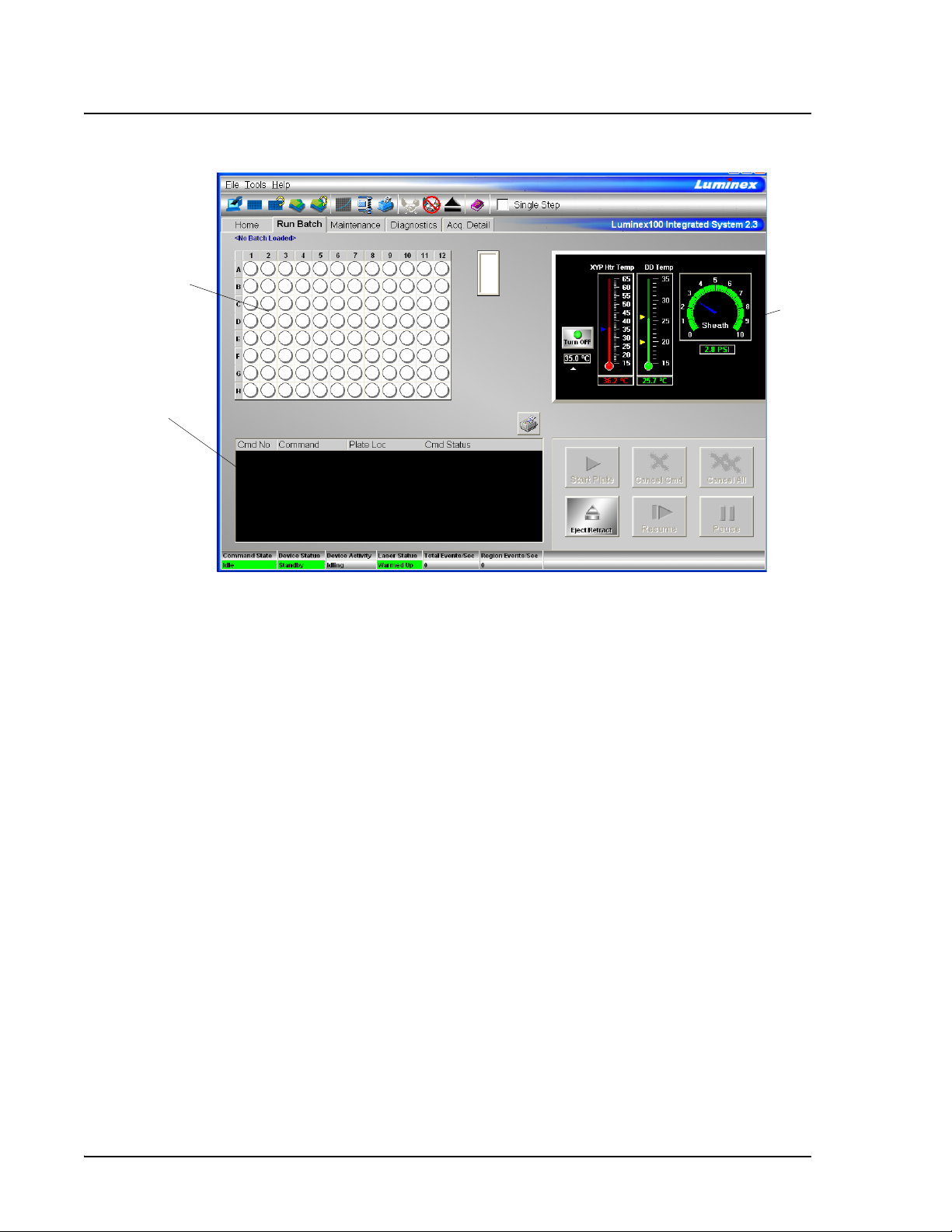
Run Batch Tab The Run Batch tab contains a microtiter plate and reservoir image,
XYP and DD temperature readbacks, a sheath pressure gauge, print
button, command list displaying batch commands and their status,
and plate and XYP command buttons. See Figure 4.
PN 89-00002-00-254 Rev. B 5
Page 16
Luminex IS Software Manual for Version 2.3- For In Vitro Diagnostic Use xMAP Technology
1
3
2
1. Microtiter plate/reservoir image 2. Temperature and Pressure Gauges
3. Command List
Figure 4 Run Batch Tab
The command buttons on the Run Batch tab are:
• Print Worklist • Eject/Retract
•Start Plate •Resume
• Cancel Command • Pause
• Cancel all
For more information on these commands, see the Commands
section, starting on page 29. For more information on setting up
batches, see See “Batch Setup Procedures” on page 49.
The microtiter plate and reservoir image represents where you
place samples or other fluids used in running or maintaining the
system. Samples are analyzed vertically, from top to bottom within
the column, and then from left to right for subsequent columns.
The Temperature and Pressure Gauges show information about the
analyzer and the XYP instrument. The XYP heater temperature
measures the internal Luminex XYP instrument plate temperature.
The DD temperature measures the doublet discriminator temperature.
DD temperature shifting indicates a need for system recalibration. If
you have not calibrated, the arrows showing the temperature range
6
Page 17

xMAP Technology Luminex 2.3 Software
for the DD temperature both appear at the bottom of the
thermometer, and the thermometer appears in red. An out-of-range
temperature logs an error, but does not halt the acquisition.
For information on setting the XYP instrument heater temperature,
see page 43.
The Command List displays commands associated with batches,
new advanced batches or multi-batches loaded for processing on the
system. The Command List shows the status of each command as the
system processes it, and whether the command completes
successfully or fails. Figure 5 shows that the first two commands
were successful, the third command is running, and the rest of the
commands are pending. Figure 6 shows that the third command
failed.
Figure 5 Command List Section of the Run Batch Tab
Figure 6 Command Failure Notation in the Command List
Errors are recorded in the Message Log on the Diagnostics tab. See
page 9 for more information about the Diagnostics tab. Double-click
on failed commands in the Message Log for additional information.
You can right-click a highlighted row to copy data to the clipboard or
clear the batch from the screen.
PN 89-00002-00-254 Rev. B 7
Page 18

Luminex IS Software Manual for Version 2.3- For In Vitro Diagnostic Use xMAP Technology
Maintenance Tab Use the Maintenance tab to perform maintenance, XYP, daily startup,
calibration, and verification commands to maintain your system and
keep it in optimal working order.
Figure 7 Maintenance Tab
See the Commands section starting on page 29 for detailed
information about these commands:
•Warmup
•Prime
•Backflush
• Alcohol Flush
• Sanitize
•Wash
•Drain
•Soak
• Self Diagnostics
• Calibration Commands: CAL 1, CAL2, CON 1, CON2, New
CAL target and New CON target
• Sample Probe Down
• Eject/Retract
8
Page 19
xMAP Technology Luminex 2.3 Software
Instructions for maintenance procedures begin on page 83. Table 8
on page 83 shows a recommended use schedule for maintenance
operations.
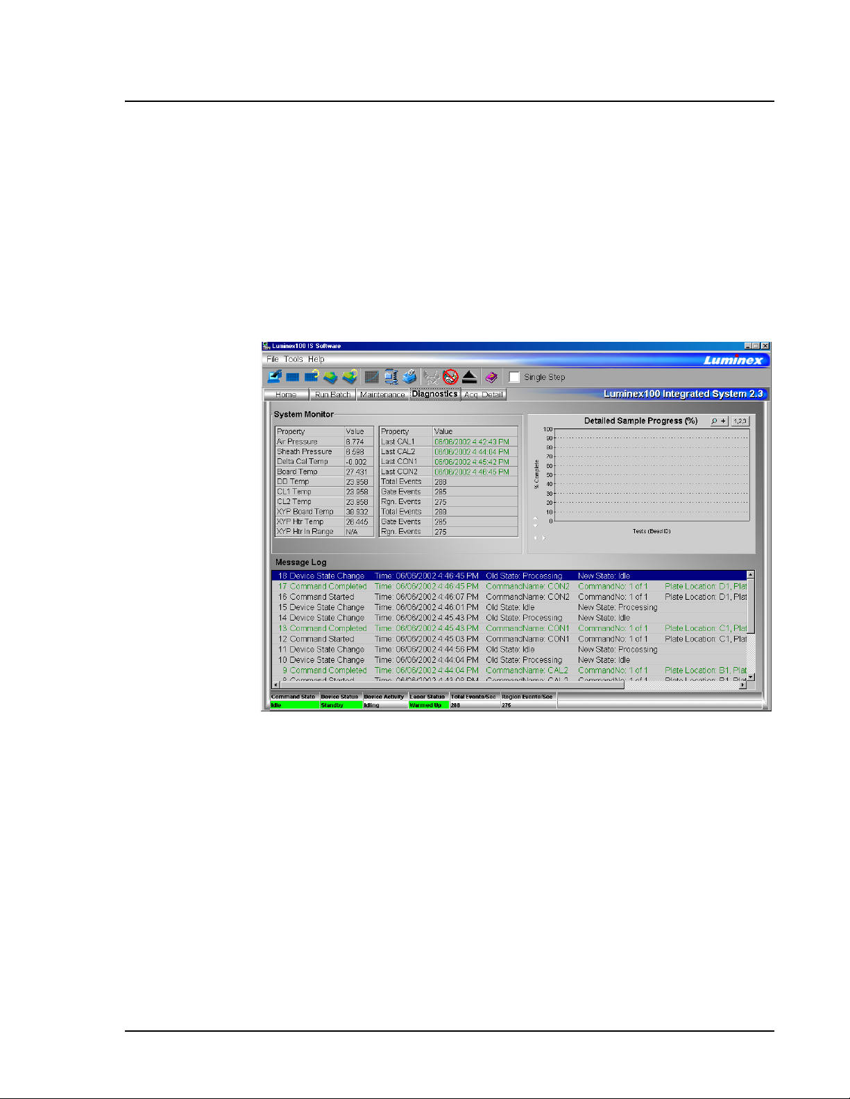
Diagnostics tab Use the Diagnostics tab to monitor the progress of commands you
initiate in the system. Features on this tab monitor the state of system
components. This tab displays the System Monitor, Detailed Sample
Progress chart, and Message Log. The Text on the Diagnostics tab
turns red if the system encounters an error. The Message Log on the
Diagnostics tab indicates where the error occurred.
Figure 8 Diagnostics Tab
Use these tools to find information about the system and what occurs
during sample acquisition and other functions. For example, you may
look on the Message Log to see the last completed command or the
one currently in progress.
The System Monitor provides information about the physical state
of the Luminex analyzer including lasers and system calibration
status. The values displayed are reported directly from the Luminex
analyzer and the Luminex XYP instrument. It shows whether the
calibration or control results completed successfully by displaying
green text for successful events and red text for failed events.
The system diagnoses real-time system problems related to fluidics
and optics. The system also detects and reports if the Luminex XYP
PN 89-00002-00-254 Rev. B 9
Page 20

Luminex IS Software Manual for Version 2.3- For In Vitro Diagnostic Use xMAP Technology
heater block temperature is out of range or experiencing
unacceptable temperature conditions, including these items:
• Luminex XYP heater block temperature time-out
• heat circuit failure
• temperature out-of-range sensing
• temperature change since calibration, or a change in channel
temperature
Table 1 defines the values listed in the System Monitor. These values
are useful for diagnostic purposes when communicating with
Luminex Technical Support.
Table 1. System Monitor Values
Property Value Units of Measure
Air Pressure PSI, air pressure to the sheath
container from the air pump
Sheath Pressure PSI, sheath pressure from the
sheath container through the
system
Delta Cal Temperature °C, temperature deviation from
the last calibration
Board Temperature °C, temperature of the analog
board
DD Temperature °C, DD temperature at the U
block inside the optics platform
CL1 Temperature °C, CL1 temperature at the U
block inside the optics platform
CL2 Temperature °C, CL2 temperature at the U
block inside the optics platform
XYP Board Temperature °C, temperature of the XYP
board inside the Luminex XYP
instrument
XYP Heater Temperature °C, temperature of the XYP
heaters inside the Luminex
XYP instrument
XYP Heater Temperature In
Range
Indicates if the XYP heater is in
the set range
10
Page 21

xMAP Technology Luminex 2.3 Software
1
2
3
The Detailed Sample Progress section displays the percentage of
completion for each bead ID or test. The graph shows real-time
progress, so that as each sample is analyzed, the graph adjusts to
show progress. Use the zoom button to view up to 20 tests at a time.
Use the toggle button to view the bead ID or test name. Use the
Expand Margin (up/down and left/right) arrows to expand the chart
margins and view longer test names. See Figure 9.
.
1. Zoom button
2. Toggle button
3. Expand Margin arrows
Figure 9 Detailed Sample Progress
The Message Log is the lower pane on the Diagnostic tab. It displays
a list of completed commands, errors, and warnings. It also displays
command progress, time and date, and results. See Figure 10.
Figure 10 Message Log
The log displays actions in color-coded text and shading. Items in the
Message Log appear in the following color codes:
PN 89-00002-00-254 Rev. B 11
Page 22

Luminex IS Software Manual for Version 2.3- For In Vitro Diagnostic Use xMAP Technology
Caution: Do not alter kit manufacturer’s predefined templates or
create alternative templates for off-the-shelf IVD kits.
• Green text represents a successful system calibration,
verification command, acquisition, or maintenance functions.
• Red text represents failed commands, errors, or warnings.
• Black text represents normal processes and actions.
• Yellow shading indicates that a detailed description about the
Note: The Message log can be
found at:
processes or actions is available. This color may vary depending
on your tool tip color system settings.
C:\Program Files\Luminex\Luminex
100 IS\MessageLog
Acquisition Detail
Tab
To view details of a message, double-click the shaded row. A
dialog box opens providing details. To clear the Message log,
right-click in the Message Log area, and click Clear on the menu.
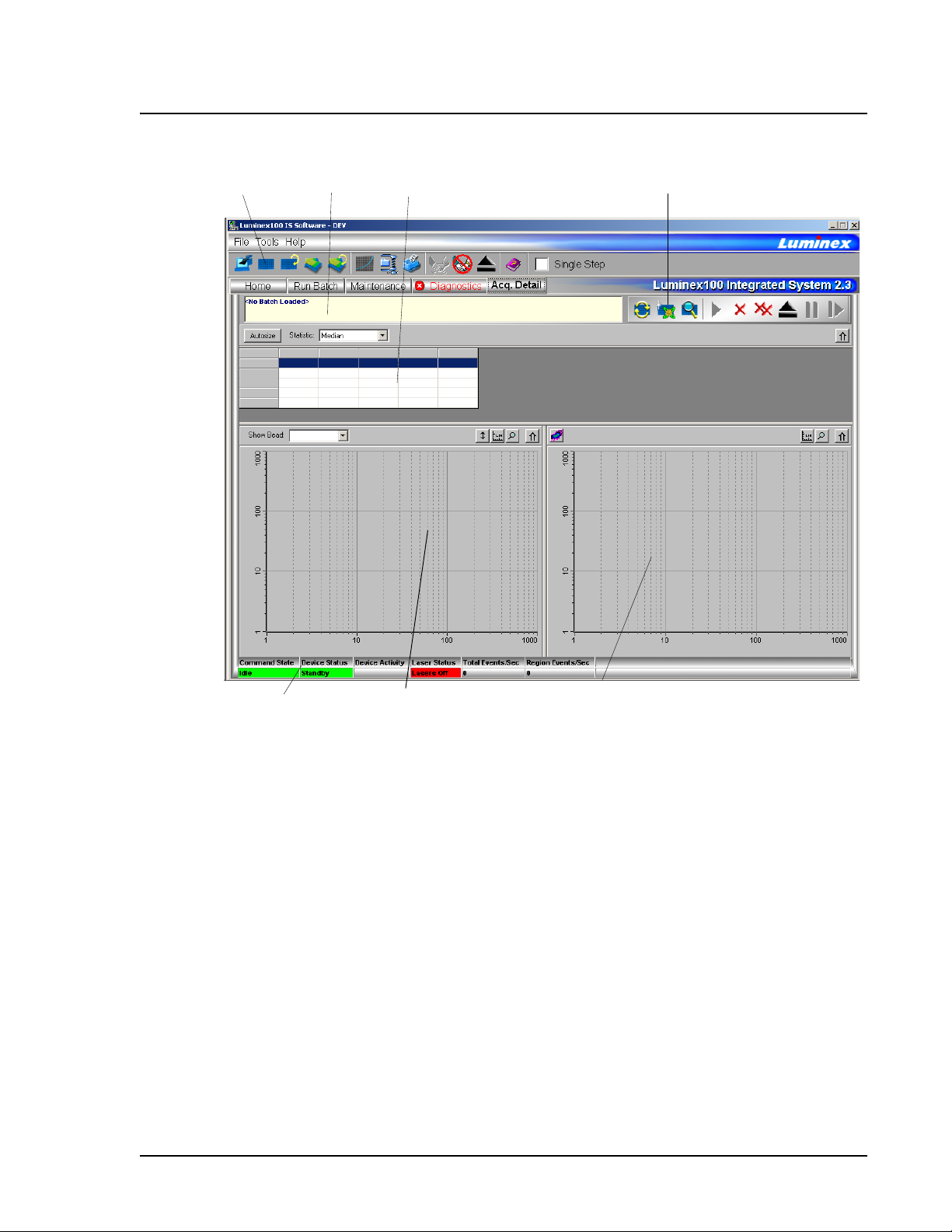
The Acquisition Detail tab offers advanced batch sample monitoring
and “on the fly” data acquisition without templates. The primary
function is real-time monitoring of batch sampling during acquisition
through a display of sample bead statistics, histogram, and dot plot
data.
During batch acquisition, bead statistics can be useful if batch errors
occur. For example, if samples are constantly failing due to
insufficient bead count, you can monitor whether the failure is due to
low bead concentration or if other assay problems are present.
Acquisition Detail tab features:
• Batch Name and Description
• Batch Data Area
• Acquisition Detail Toolbar
• Histogram
• Dot Plot
Acquisition Detail tab features:
• Batch Name and Description
• Batch Data Area
• Acquisition Detail Toolbar
• Dot Plot
Figure 11 identifies the major features of the Acquisition Detail tab.
12
Page 23
xMAP Technology Luminex 2.3 Software
1
2
3
4
5
7
6
1. Luminex IS 2.3 Toolbar 5. Status Bar
2. Batch Name and Description 6 Histogram
3. Batch Data Area 7 Dot Plot
4. Acquisition Detail Toolbar
Figure 11 Acquisition Detail Tab
The Batch Name and Description section displays the name of the
batch as well as its description.
The Batch Data area displays sample results. The left column shows
plate location and Sample ID description. The remaining columns
display selected bead sets for the assay. Each row represents the data
for each bead set from one well.
The Acquisition Detail Toolbar shown in Figure 12 provides
functions to acquire raw data without using templates. For more
information about the commands on the Acquisition Detail Toolbar,
see the Command section, beginning on page 29.
PN 89-00002-00-254 Rev. B 13
Page 24

Luminex IS Software Manual for Version 2.3- For In Vitro Diagnostic Use xMAP Technology
12
3
4
5
67
89
1 Replay Batch 6 Cancel All
2 New Advanced Batch 7 Eject/Retract
3 View Batch Data 8 Pause
4Start Plate 9Resume
5 Cancel Command
Figure 12 Acquisition Detail Toolbar
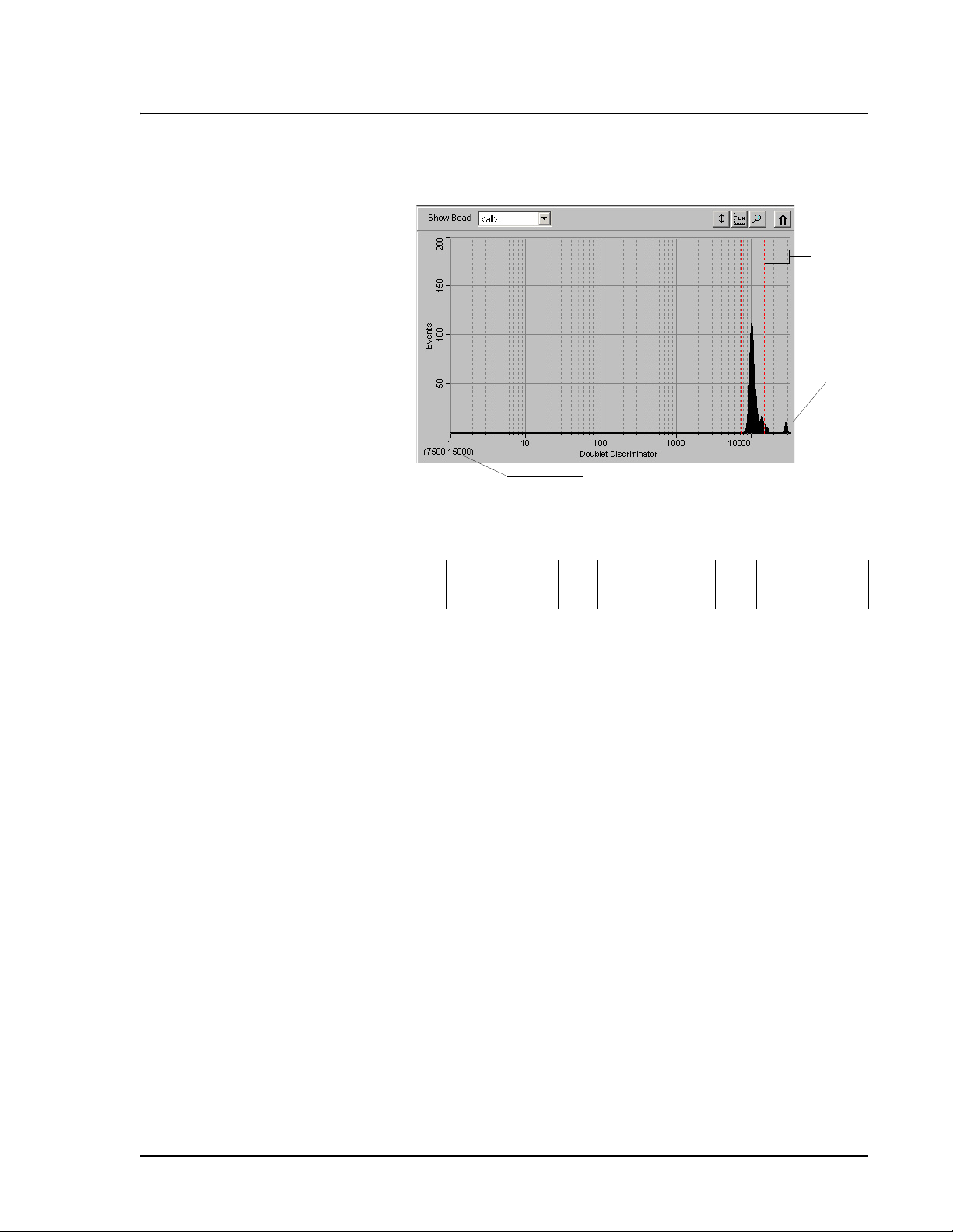
The Histogram, in the lower left section of the Acquisition Detail
tab, defaults to display the Doublet Discriminator (DD) on the X axis
and Events on the Y axis. Doublets appear when two microspheres
stick together, creating undesired results. When you enable the gate,
two vertical red, dashed lines appear to represent gate positions
determined by the template. You cannot change the gate position
during batch acquisition. You can change the gate positions before
data acquisition, after the system finishes acquiring data, or after
pausing the system. The change is visual. The data is still collected
according to the gate positions set in the assay template. The gate in
effect when the system collects data determines which values to use
to obtain the result. Applying a gate or changing a gate for existing
data does not change your calculated values. The gate positions, also
located in the lower corner of the histogram, are used while
collecting data are the numerical values selected in the template.
14
Page 25
xMAP Technology Luminex 2.3 Software
1
2
3
1Gate
Boundaries
2 Aggregate
Beads
Figure 13 Set DD Gate Example
3 Numerical
Gate Position
The Histogram contains the Show Bead menu and four buttons:
• Autoscale
•Zoom
• Log/Linear
• Maximize
For more information on these commands, see the Commands
section beginning on page 29.
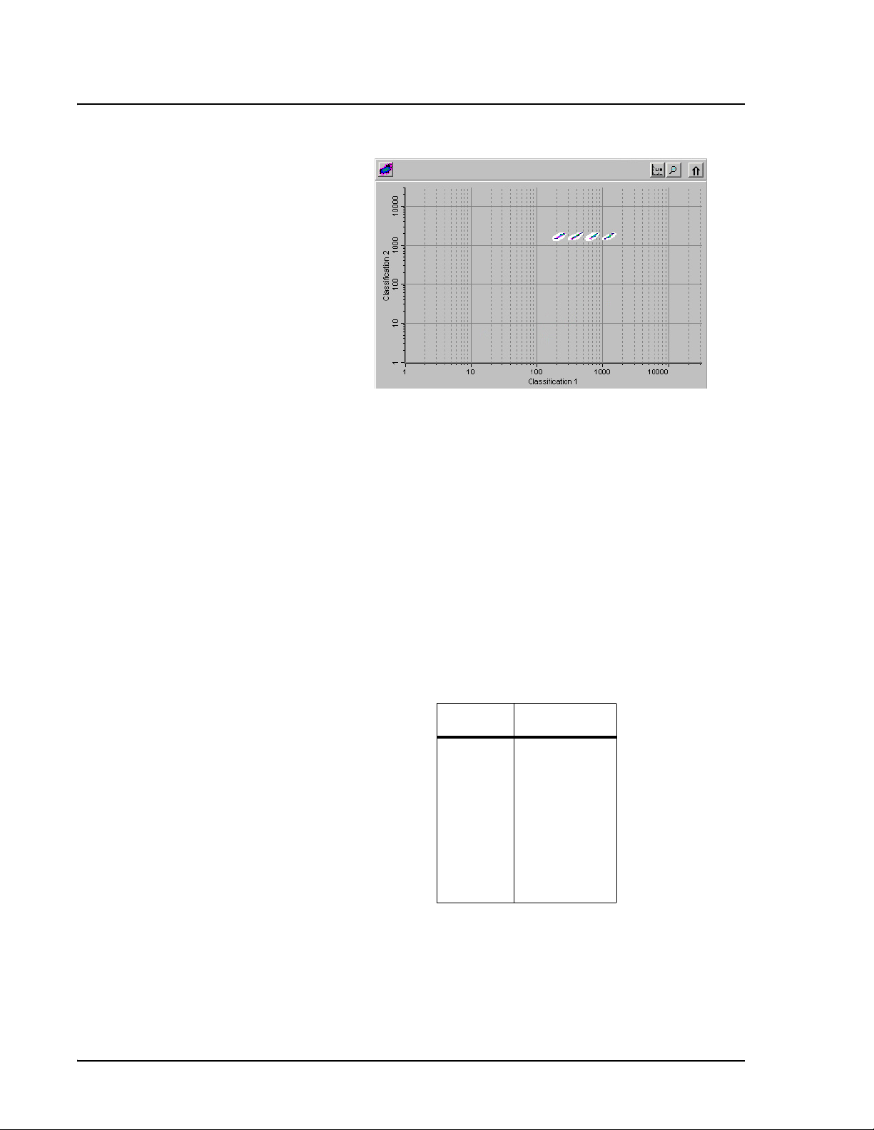
The Dot Plot (or bead map) appears in the lower-right section of the
Acquisition Detail tab. See Figure 14. The dot plot shows a graphical
display of real-time data collection.
Luminex recommends using the default settings to collect data. The
default axes are Classification 1 on the X axis and Classification 2 on
the Y axis. To see the dot plot, you must use the default axis. To
display the bead set information, hover the mouse pointer over the
desired region. You can change the X axis and Y axis of the dot plot
for troubleshooting purposes, although you should use the default
settings in all other scenarios.
PN 89-00002-00-254 Rev. B 15
Page 26
Luminex IS Software Manual for Version 2.3- For In Vitro Diagnostic Use xMAP Technology
Figure 14 Dot Plot Display Example
Four buttons appear at the top of the frame to control the display:
• Density/Decaying
• Log/Linear
•Zoom
• Maximize
You can toggle between two types of dot plots using the Density/
Decaying button. The Decaying Dot Plot plots only the 100 mostrecent acquired events. The Density Dot Plot displays a constant
accumulation of events. Increasing density is indicated by
contrasting colors. See Table 2 for the density dot plot color legend.
Table 2. Dot Plot Color Legend
Layer Color
0
1
2
3
4
5
6
7
8
none
dark blue
pink
dark green
cyan
light blue
light green
orange
dark red
The density dot plot allows visual elimination of data values
determined to be insignificant to the display. Luminex recommends
you collect your data in density dot plot mode to observe all
collected events. Post acquisition does not display decaying dot plot;
it’s only a real-time function.
16
Page 27
xMAP Technology Luminex 2.3 Software
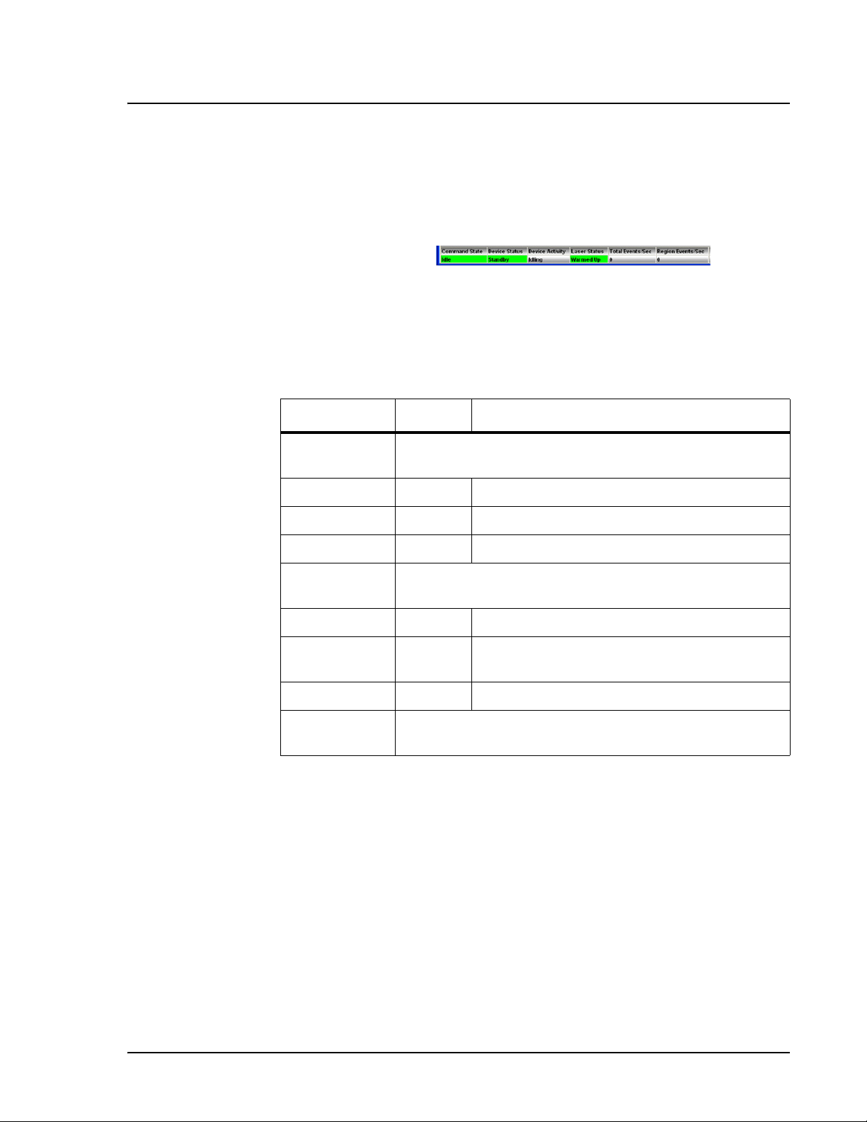
Status Bar The Status Bar displays information about the Command State,
Device Status, Device Activity, Laser Status, Total Events per
Second, and Region Events per Second. Color coding indicates the
urgency of each item’s status. Device Activity uses no color coding.
Figure 15 System Status Bar
Table 3 describes the types of status bar messages in relation to the
message color coding.
Table 3. Status Bar Color Coding
Category Color Indicates
Command
State
Device Status Indicates the current process of or warning about the
Device
Activity
Indicates communication status of the Luminex analyzer or
operations being processed
Green Idle or processing
Yellow Connecting, pausing, or paused
Red Disconnected or locked out
Luminex analyzer
Green Running or standby
Yellow Busy, pressurizing, sheath is empty, or warming
up
Red Not ready or disconnected
Indicates the activity that the Luminex analyzer is
performing. Note: The device activity has no color code.
PN 89-00002-00-254 Rev. B 17
Page 28
Luminex IS Software Manual for Version 2.3- For In Vitro Diagnostic Use xMAP Technology
Table 3. Status Bar Color Coding (Continued)
Category Color Indicates
• Idling: waiting for a command
• Aspirating: drawing in sample
• Collecting Data: collecting data
• Sanitizing: sanitizing the instrument
• Washing: washing the sample line
• Priming: priming the instrument
• Calibrating: calibrating the instrument
• Canceling: canceling a command
• Backflushing: backflushing the instrument
• Draining: draining the instrument
• Warming Up: warming up the instrument
• Verifying: verifying calibration
• Soaking: soaking the probe
• Adjusting sample probe
• Self Diagnosing: performing self-diagnostic
routine
Laser Status Laser temperature and readiness status
Green Lasers warmed up
Yellow Warmup timer countdown in seconds from 1800
Red Lasers off
Total Events/
Second
Region
Events/
Second
Number of total bead events detected per second
Number of bead events detected per second that are
classified in a region
The Status Bar displays status information as the software processes
commands. Table 4 shows the typical messages that appear in the
status bar. Additionally, information displays as text on the
Diagnostics tab.
Table 4. Status Bar
Communication Message Details
Status Bar
Color
Message Indicates
18
Green Idle Waiting to process the next
command.
Page 29

xMAP Technology Luminex 2.3 Software
Table 4. Status Bar
Communication Message Details (Continued)
Status Bar
Message Indicates
Color
Standby The Luminex analyzer is ready
and waiting to perform a
command.
Yellow Connecting The software is attempting to
connect to the instrument.
Processing The instrument is communicating
with the software as it processes
commands.
Pausing The instrument has stopped
processing the list of commands,
but finishing the active command.
Paused The software stopped processing
the list of commands. A “resume”
function becomes available to
change the state back to
“processing.”
Busy The instrument is processing a
maintenance command.
Red
Disconnected
The software has not yet
attempted to connect or fails to
connect to the instrument.
Locked Out Another application currently has
control of the instrument. The
software locks out as long as the
other application runs. To remove
the locked out status, close the
other application or wait until the
application completes.
PN 89-00002-00-254 Rev. B 19
Page 30

Luminex IS Software Manual for Version 2.3- For In Vitro Diagnostic Use xMAP Technology
Secondary Windows
In addition to the main window, there are other windows that are
displayed when you select certain commands. These are the Batch
Setup Window and Analysis Window.
In the Batch Setup window, you define information used to create
batches. All of the commands are on the same page; there are no
tabs. The window opens when you click New Batch and select a
template.
20
The following features are part of the Batch Setup Window:
• Batch Info group box
• Template Info group box
• Insert command
• Command list
• Microtiter Plate image
• Command button group box
• Save group box
• Standard Info group box
Page 31

xMAP Technology Luminex 2.3 Software
• Control Info group box
• New Lot button
The Batch Info group box has text boxes in which you can input the
name, description, and creator name of a new batch.
The Template Info group box shows the name, description, version
number, and developing company for the template that you are using
in a batch.
The Insert command lets you insert a patient into a batch or skip a
well.
The Command list displays the commands that were imported from
the template, plus commands added using the Insert command or
manually entered. The lock in the far left column indicates that the
command was imported from the template and cannot be changed in
the Batch Setup window.
The Microtiter Plate image reflects the command information for
each well, as defined in the template.
The Command button group contains the Finish, Cancel, Load Pa
List, and Help command buttons. For more information on these
commands, see the Commands section, beginning on page 29.
The Save group box contains the Save and Load and Save only
option buttons. For more information on these commands, see the
Commands section, beginning on page 29.
The Standard Info group box is visible only if the template you are
using requires the use of standards. If standards are used in the
template, the Standard Info group box reflects the Standard
information as defined in the template product.
The Control Info group box is visible only if the template you are
using requires the use of controls. If controls are used in the
template, the Control Info group box reflects the Control information
as defined in the template products.
The New Lot button is visible only if the template you are using
requires the use of standards or controls. The button opens the
Update Lot Information dialog box, in which you can manage lot
information.
Analysis Window When the system analyzes batches, it displays the data in a three-tab
format within the Analysis window. The following three tabs present
the batch information in greater detail:
PN 89-00002-00-254 Rev. B 21
Page 32

Luminex IS Software Manual for Version 2.3- For In Vitro Diagnostic Use xMAP Technology
• Errors tab—lists errors that occur during batch acquisition, such
as controls that failed.
• Standards tab—lists all tests in the batch, a regression chart for
each test, and the standards or controls associated with the batch.
• Samples tab—lists background samples and all samples or
unknowns acquired in the batch with either a qualitative or
quantitative result.
Eight function buttons are available on the lower portion of the
Analysis window. These buttons perform tasks or functions that are
relevant to the Standards tab although they appear on all three tabs of
the Analysis window. The buttons are:
• Next Test (F2)
• Previous Test (F3)
• Invalidate Standard (F4)
• Validate Standard (F5)
• Invalidate Control (F6)
• Validate Control (F7)
• Change Lot (Alt + F8)
• Recalc (Standards tab only) - only available on the Standards tab,
and only if the Auto checkbox is not selected.
For a description of these commands, see “Commands” on page 29.
For information on procedures using these commands, see
“Validating or Invalidating Standards and Controls” on page 75 and
“Change Lot” on page 76.
In addition to the function buttons, you can choose to sort data
sequentially by order acquired, or alphabetically by Sample ID.
These options are available in the Sort group box next to the function
buttons. These sorting functions are helpful in viewing batches
containing replicate samples. Replicate samples are defined as
samples with identical sample identifications. Replicate standards,
controls, and unknown samples are not always acquired in sequential
wells and thus make sample viewing difficult. When viewing
samples alphabetically all replicate samples are displayed together
with the replicate sample’s average (AVG), then individual samples.
If you view replicate batches sequentially, each sample displays in
the order it was acquired, followed by a replicate average summary
section.
Errors Tab The Errors tab displays a list of errors that occurred during
acquisition. It organizes the errors in two categories: System and
assay errors (top section of tab), and Sample errors (bottom section
of tab) Table 5 lists the errors in each category
22
Page 33

xMAP Technology Luminex 2.3 Software
Figure 16 Analysis Window - Errors Tab Open
Table 5. Error Categories
System and Assay Errors Sample Errors
• Instrument Not Calibrated
• Failed Verification (system lists
each failed control)
• Failed Control (verifier failed)
• Temperature Divergence from
Calibration Temperature
• Failed Curve Fit
• Analysis Error
• APD Temp Range Exceeded
• XYP Temp Unstable
•Low Voltage
• High Sheath Pressure
• Low Sheath Pressure
• Command Timeout
• Low Laser Power
• Cannot Calculate Inverse
Function
• Failed Std in Batch
• Insufficient Bead Count
• Sample High/Low
• Analyzer Error
• High Sheath Pressure
• Low Sheath Pressure
• Sample Timeout
• Sample Empty
• Cannot Calculate Inverse
Function
• Different Qualitative Results
Standards Tab The Standards tab lists all the batch tests with system comments
specific to each test. The detailed test information that is displayed
PN 89-00002-00-254 Rev. B 23
Page 34

Luminex IS Software Manual for Version 2.3- For In Vitro Diagnostic Use xMAP Technology
on the three tabs of the Analysis window is determined by the test
selected under the Standards tab.
The Standards tab displays the quantitative batch’s standard curve. It
displays qualitative batches as a graph plotting the assay standard.
Above the graphical information, the tab displays the formula that it
used to calculate batch data. Below the graphical information, the tab
displays the Standards and Controls values for the selected test.
24
Figure 17 Analysis Window - Standards Tab Open
When a median fluorescence intensity (MFI) value for an unknown
sample or control lies outside the standard curve MFI range, the
concentration is not calculated. The unknown sample or control
result is reported as less than (<) or greater than (>) next to the
corresponding standard expected concentration. The out-of-range
samples and controls will also have a “Sample High/Low” statement
in the comment column. If a sample lies within the standard curve
MFI range, but the sample’s MFI value does not intersect the curve,
the result will be reported as “Error”. A “cannot calculate inverse
function” statement displays in the comments column. This error
condition usually occurs when a standard curve “flattens out” at the
high or low end. Examples of out-of-range sample labeling for non-
Page 35

xMAP Technology Luminex 2.3 Software
competitive assays are shown in Table 6. Figure 18 shows what a
standard curve for a non-competitive assay should look like.
Table 6. Non-Competitive Out-Of-Range Labeling
Condition Concentration Label MFI of Standard Referenced
Left of Curve < min concentration standard Lowest
Right of Curve > max concentration standard Highest
Figure 18 Non-Competitive Assay
Examples of out-of-range sample labeling for competitive assays are
shown in Table 7. Figure 19 shows what a standard curve for a
competitive assay should look like.
Table 7. Competitive Out-Of-Range Labeling
Condition Concentration Label MFI of Standard Referenced
Left of Curve < min concentration standard Highest
Right of Curve > max concentration standard Lowest
PN 89-00002-00-254 Rev. B 25
Page 36

Luminex IS Software Manual for Version 2.3- For In Vitro Diagnostic Use xMAP Technology
Figure 19 Competitive Assay
The standards tab displays an Expected Concentration column for
standard and control samples. The Standards Expected Concentration
column allows users to edit the standard concentrations. You can edit
controls; however, you must select the control name or Expected
Concentration box for that control, then click Change Lot.
When editing standard and control lot values the system may prompt
you for a new number. If this is the first batch you analyze using this
lot number, the system allows editing without requiring a new lot
name. However, if you have analyzed a previous batch using this lot,
the system will require that you rename the lot if edited or modified.
Samples Tab The Samples tab lists tests from your batch and displays the results
for each sample.
Figure 20 shows a Sample tab example listing three tests. Notice that
the left pane displays Test IL-4, IL-6 and IL-8 with Test IL-4
selected. The right pane shows the IL-4 sample results. Notice that
the well G3 location test result is “<10” and the associated
Comments column for the third sample indicates a sample out of
range error “Sample High/Low” because this sample has an MFI less
than the lowest standard in the standard curve for this noncompetitive batch.
The first sample is within the standard curve range and thus displays
an unflagged test result.
26
Page 37

xMAP Technology Luminex 2.3 Software
The system does not flag results as normal or abnormal according to
a defined range. Error flags only note samples that fall below or
above the standard curve.
The Comments column cells are editable and the information is
displayed in reports.
Figure 20 Analysis Window - Samples Tab Open
Replicate
Averaging
Standard and control replicates are predefined in the template. You
define unknown sample replicates in batch setup indicated by
replicate Sample ID.
The data analysis function supports replicate sampling. It calculates
each sample as an individual sample, which is then averaged to
obtain a replicate average.
• Standards tab—displays standard and control average values.
• Samples tab—displays sample average values.
Replicate averages are displayed with AVG in the Loc (location)
column.
PN 89-00002-00-254 Rev. B 27
Page 38

Luminex IS Software Manual for Version 2.3- For In Vitro Diagnostic Use xMAP Technology
The AVG entry appears immediately after the wells being averaged
or at the end of the list depending on what you select under Sort
(Sequentially or Alphabetically). Follow the IVD kit package insert
instructions for use regarding number of replicates to run for a
particular assay.
If the system fails to determine the results for a replicate due to an
excessive skew of one of the samples, you can invalidate the out of
tolerance value. Use the Invalidate Standard (F4) or Invalidate
Control (F6) buttons at the bottom of the Analysis window. Be
aware that this fixes standards and controls, not patient sample. If
any of the replicate standards and/or controls are invalidated, the
“Avg” results reflects the average of the remaining standard and/or
control replicates.
The system flags the failed sample so you may calculate the replicate
set’s average without including the failed result in the equation.
You can sort the batch samples Sequentially (by the order in which
they are acquired), or Alphabetically (by sample ID). Select the
sorting method in the Sort group box. Follow the IVD kit package
insert instructions for use regarding number of replicates to run for a
particular assay.
28
Page 39

xMAP Technology Luminex 2.3 Software
Commands This section describes the different commands used in the Luminex
IS 2.3 software. They are grouped Alphabetically.
Acquire Patient This command, which is part of the Insert command/menu, adds
patients to the command list. After adding the patients you define the
Sample ID and Dilution Factor for each new patient. The Dilution
Factor defaults to 1.
Add Batch When creating a multibatch, adds an existing batch to a multi-batch.
Alcohol Flush Removes air bubbles from the sample tubing and the cuvette using
70% isopropanol or 70% ethanol. The alcohol flush takes about five
minutes. Uses the Luminex XYP reservoir due to volume
requirement.
Autoscale Automatically adjusts the maximum number of events shown on the
Y axis on the histogram. Click during acquisition to readjust the Y
axis scale.
Autosize Automatically adjusts column widths to fit the data and header sizes.
Backflush Removes obstructions from the fluidics pathways by drawing sheath
fluid from the sheath fluid container. You do not need to supply
solution in a plate. A backflush command takes about seven seconds.
CAL1 Runs the Classification portion of the Luminex System calibration.
CAL2 Runs the Reporter portion of the Luminex System calibration.
Cancel (Command) Cancels the process for the last command initiated.
Cancel All Cancels all the commands in progress.
Change Lot Opens the Change Lot dialog box from which you select a lot to
apply to a batch.
CON1 Runs the verification for the Classification calibration.
CON2 Runs the verification for the Reporter calibration.
Connect to Instrument Establishes a connection between the PC and the analyzer.
PN 89-00002-00-254 Rev. B 29
Page 40

Luminex IS Software Manual for Version 2.3- For In Vitro Diagnostic Use xMAP Technology
Create New Multi-Batch This command opens the Luminex Multi-Batch dialog box, in which
you add or create new batches to add to a multi-batch.
Delete Batch Opens the Delete Batch dialog box, which shows a listing of the
unprocessed batches in the database. When you highlight a batch and
click Select in this dialog box, the system deletes the selected batch.
Density/Decaying Toggles between the default density dot plot and the decaying dot
plot views.
Disconnect from
Disconnects communication between the PC and the analyzer
the Instrument
Display Confirmation Screens
Enables confirmation dialog boxes to display when you initiate many
of the maintenance commands.
Drain Used during troubleshooting to help remove debris from the bottom
of the cuvette. When draining, you do not need to supply solution.
Draining takes approximately two minutes and should be followed
by an alcohol flush with 70% isopropanol or 70% ethanol. Any fluid
that drains from the system drains to the Luminex XYP reservoir as
the default. However, you can set the system to drain to any unused
well on the microtiter plate. The drain function normally expels 125
µL of fluid.
Eject/Retract If the XYP plate is retracted, this command ejects the microtiter
plate. If the XYP plate is already ejected, this command retracts the
plate.
Enable Raw Data Storage Saves bead event data to the database.
Export Batch Data Opens the Open Batch dialog box, from which you choose a batch to
export to an output.csv file.
Export CAL Opens a dialog box in which you choose the calibration file to export
to an output file.
Export CON Opens a dialog box in which you choose a control (validation) file to
export to an output file.
Export Data Exports data to a .csv file in the batch folder. There is no dialog box
to confirm that the data was exported.
30
Page 41

xMAP Technology Luminex 2.3 Software
Help Opens the help file. Use this command if you need instructions on
using a feature in the Luminex IS 2.3 software.
Import Calibration Opens a dialog box in which you select a calibration file that
contains calibration lot information to import to use for calibrating
the analyzer.
Import Control Opens a dialog box in which you select a control file that contains
control lot information to import for use when verifying calibration.
Import Template Opens up the Import Template dialog box, from which you select a
template to import for use in a batch.
Insert This combination menu/command on the Batch Setup window
allows you to add a user-defined number of patients to the command
list, or skip a defined number of wells on the microtiter plate. The
two options on the menu are Acquire Patient and Skip.
Invalidate Control Invalidates or removes a control from the data analysis. Luminex
does not recommend invalidating controls.
Invalidate Standard Removes a standard from the data curve. Use this command if doing
so improves the curve fit. Use caution when doing so because
invalidating a standard will greatly affect the curve fit and
subsequently the sample results.
Load Patient List Opens the Open Patient List File dialog box, from which you select a
patient list text file to append to a batch.
Log/Linear Toggles the x axis scale on the histogram or dot plot between
logarithmic and linear modes.
Maximize/Minimize Toggles between maximum and minimum histogram and dot plot
views.
Next Test This command is found in the Analysis window. Use this command
to view the next test in the batch.
New Advanced Batch Use New Advanced Batch to acquire data without having to build
templates. This provides a faster and more convenient tool. It does
not store the results in the Luminex IS 2.3 database. It writes raw
data to the output.csv file if Auto Export is selected, and writes run
files if Enable Raw Storage is selected. This feature is the primary
use of the Acquisition Detail tab. When you click on the New
PN 89-00002-00-254 Rev. B 31
Page 42

Luminex IS Software Manual for Version 2.3- For In Vitro Diagnostic Use xMAP Technology
Advanced Batch button, the Options dialog box opens, where you
enter information about the batch, define bead events for the session,
and define commands for plate layout.
New Batch Opens a dialog box in which you select a template to create a new
batch in the Luminex Batch Setup window.
New CAL Targ. Opens the Update CAL Targets dialog box, in which you enter
information about the calibration microspheres you are using to
calibrate the system.
New CON Targ. Opens the Update CON Targets dialog box, in which you enter
information about the control microspheres you are using to verify
system calibration.
New Lot Opens the Open Template dialog box, from which you select a
template to which you want to add a lot or edit lot information.
Open Batch 1. The Open Batch command selected from the file menu or toolbar
opens the Open Batch Dialog box, from which you choose an
existing batch to use for acquisition.
2. The Open Batch command on the Analysis window allows you
to view data from a different batch.
Open Help Opens the online help file.
Open Incomplete Batch Opens the Open Run dialog box, in which you select a batch to
recover.
Open Multi-Batch Opens the Open Multi-Batch dialog box, in which you select a multi-
batch to use for acquisition.
Pause Pauses the command that the system is currently processing.
Previous Test This command is found in the Analysis window. Use this command
to view the previously run test in the batch.
Prime Removes air from the system’s fluidic pathways by drawing
Luminex xMAP Sheath Fluid from the sheath fluid container. You do
not need to supply solution in a plate. Priming takes approximately
one minute. This command should also be used as part of the daily
startup routine.
32
Page 43

xMAP Technology Luminex 2.3 Software
Print Batch Worklist Prints the status of each of the commands in the command list, as
well as the microtiter plate graphic.
Print Report Prints the data interpretation report including the standards, controls,
graph of standards, and Samples data.
Replay Batch Replays batch sample acquisition. All batch commands are replayed
allowing for batch acquisition viewing exactly as in real-time. You
cannot replay New Advanced Batches. When running a Replay
Batch command, the original acquisition data is not altered. A new
file is created. The most common use is for system demonstration
and training.
Report Raw Fluorescence Enables the median fluorescence intensity (MFI) to appear on the
Analyte Report.
Resume Resumes the process that was paused.
Sample Probe Down Raises and lowers the sample probe to adjust the probe height. This
adjustment is recommended when using different microtiter plates or
when changing sample probes. Refer to the Luminex 200 System
Manual or the Luminex 100 IS User Manual for Version 2.3 for the
adjusting procedure.
Sanitize Uses the Luminex XYP reservoir due to volume requirement. The
sanitize command performs a similar function as the alcohol flush
command. However, the sanitize command uses 10% to 20%
household bleach to decontaminate sample lines and the cuvette after
biohazard contact.
Save and Load If selected, displays the run batch tab immediately after you set up
batch information and click Finish.
Save Only Allows you to save the batch information. User can open the batch
later to acquire data.
Self Diagnostics Performs a self-diagnostics to see if the Luminex 200 analyzer and
all system operations are functioning correctly. Self-Diagnostics tests
these functions:
• Flash memory test
• Microcontroller RAM test
• Nonvolatile memory test
• DSP program CRC test
PN 89-00002-00-254 Rev. B 33
Page 44

Luminex IS Software Manual for Version 2.3- For In Vitro Diagnostic Use xMAP Technology
• DSP capture test
• High voltage module
• Channel backgrounds test
• Pressurization test
• Actuator test
• Syringe pump test
• Backflush valve test
• Debubbler valve test
Show Bead After selecting an entry from the drop-down list, sets the histogram
to show events for only one beadset [bead set number], <all gated>
events within the gate, or <all> events inside and outside the gate.
Select <all> (default) before setting the gate.
Single Step Selecting this option on the toolbar pauses the system in between
each command or sample acquisition within a batch.
Skip [wells] Enables you to deliberately bypass specific wells during batch
acquisition.
Soak Prevents salt crystals from forming in the probe due to air exposure.
Soaking the probe replaces sheath fluid in the probe with water. You
should perform the soak function at the end of each day. The system
uses at least 250
µL of distilled water.
Start Analysis Opens the Open Batch dialog box, from which you select a batch to
analyze. Once you select the batch, the Analysis window opens.
Start (Plate) This command initiates data acquisition on New Advanced Batches
and New Batches using system templates. During acquisition, the
system draws sample from the microtiter plate for processing.
Statistics This command enables you to display selected statistics for sample
data. There are eleven different statistics: %CV, Trimmed %CV,
Count, Trimmed Count, Mean, Trimmed Mean, Median, Trimmed
Peak, Peak, Trimmed Std Dev, and StdDev.
Test Sort Orders This command is in the Data Export Tab of the Options tab. You can
select Alphabetical by test name, Sequential by Region ID, or by
Template Setup Order
34
• Alphabetical by Test Name - the tests are sorted by
alphabetical order
Page 45

xMAP Technology Luminex 2.3 Software
• Sequential by Region ID - the tests are sorted numerically by
bead ID#.
• Template Setup Order - the tests are sorted n the order set up
in template, regardless of name or ID.
Validate Control Opens the Validate Control dialog box. In this box, you choose to
validate all control tests (click Yes), or only a single test (click No).
Validate Standard Opens the Validate Standard dialog box. In this box, you choose to
validate all control tests (click Yes), or only a single test (click No).
View Batch Data Click to open a previously acquired batch that is stored in the
database. You cannot view New Advanced Batches.
Warmup Warms up the system to prepare the optics prior to sample
acquisition. The system automatically begins warming up when you
turn power on; however, you will need to use the Warmup command
if the system is idle for four hours or longer.
Wash Washes fluidics line. Sends fluid (distilled water) through the fluidic
lines in the system. Pulls the fluid from a well or the reservoir and
runs it completely through the system to the waste receptacle.
Zoom Zooms or enlarges a specific area on the histogram or dot plot
display. Click and drag right to left to adjust the graph’s range.
PN 89-00002-00-254 Rev. B 35
Page 46

Luminex IS Software Manual for Version 2.3- For In Vitro Diagnostic Use xMAP Technology
Procedures This section explains how to perform functions in the software.
Using the Online Help Help files describe Luminex System features and capabilities. You
may find these topics by searching the contents of books and topics
or by searching an alphabetic listing of the topics and books.
Top ic s provide information and details regarding software features,
system capabilities, and any number of related material.
Books usually contain a group of topics. These topics are grouped
together because they discuss similar or related topics.
Hyperlinks provide instant access to another topic or subtopic with
related information to the linked subject or term.
To open the system’s online help:
1. On the Help menu, click Contents.
2. In the Help dialog box, scroll through the contents and select the
desired topic. Also, consider the index to locate information.
3. Double-click the help topic that you want to view. A topical
dialog box opens with information on that topic.
To display device information about the Luminex analyzer,
Luminex XYP instrument, and the Luminex LXR SDK:
On the Help menu, click About the Device. The resulting dialog
box shows information that may be helpful when contacting
Luminex Technical Support. Click OK to close the dialog box.
To display information about the system software:
On the Help menu, click About the Software. The resulting
dialog box shows information about the system software. This
includes software version, build number, and the system
copyright information. Click OK to close the dialog box.
To display system information:
1. On the Help menu, click About the Software. The resulting
dialog box opens that displays software information.
36
2. Click System Info. The System Information dialog box opens.
Click X in the top-right corner to close the dialog box.
3. Click OK to close the dialog box.
Page 47

xMAP Technology Luminex 2.3 Software
Setting Software Options Set up and select the system software and enter your company
information in the Options dialog box. The Software Options dialog
box has three tabs: the General tab, the Company Information tab,
and the Data Export tab.
To configure software options:
1. On the To ol s menu, click Options.
2. Click on the tab in which you want to set options. A full
description of each tab and its options is listed below.
3. After you have entered and selected all of your preferences, click
OK.
Define General
Tab Information
You define the following options on the General tab.
Default Batch Directory. Names the default directory to store
batch information. Click the browse button and navigate to the
desired folder (directory).
Current User. Enter the name of the current user or operator. The
name appears on reports.
Analysis Display Digits. Use this feature to customize the
number of digits shown on the Data Analysis dialog box and printed
reports. The data is stored with its full precision (that is, including all
digits), but the data appears as requested. The default analysis digit
display is for two digits to show in the analysis.
Display Confirmation Screens. Enables confirmation dialog
boxes to display when you initiate many maintenance commands. If
you disable the confirmation screen display option, the confirmation
screens remain for commands initiated from the Home tab.
Enable Raw Data Storage. Select this feature to save bead event
data that is acquired while processing batches in the database. The
system defaults to Enable Raw Data Storage. Raw data storage is
necessary particularly when you use file mode (Replay Batch).
Report Raw Fluorescence. Select this feature to enable the
median fluorescence intensity (MFI) display to appear on the
Analyte Report. This feature was previously used to display MFI
values on all reports. In the Luminex IS 2.3 software, the only report
affected by this selection is the Analyte Report. All others are hard
coded by the system.
Auto-Start Analysis. Select this feature to enable the software to
begin analyzing data immediately after processing batches. The
automatic analysis feature takes place after the system finishes
acquiring data while processing batches.
PN 89-00002-00-254 Rev. B 37
Page 48

Luminex IS Software Manual for Version 2.3- For In Vitro Diagnostic Use xMAP Technology
Figure 21 Options Dialog Box—General Tab
Define Company
Information Tab
You can enter information about your company and a company logo
into the Company Information tab. This information is stored in the
Registry for reference. The logo will not alter any Luminex IS 2.3
report or screen.
Company Information (name, address, phone and fax numbers, and
location of company logo).
Use the browse button to navigate to the location where the
logo is stored.
38
Figure 22 Options Dialog Box—Company Information Tab
Page 49

xMAP Technology Luminex 2.3 Software
Define Data Export
Tab Information
Use the Data Export tab to configure your export data. See Figure 23.
The following options are available:
Auto Export Batches. Select this feature to automatically export
the .csv file formats when the system finishes analyzing the batch.
This allows you to run your own programs on exported data without
having to manually start the export. This feature also takes place
after acquisition completes. If this is not selected while running a
New Advanced Batch, you must right-click on the data grid to get
your output.csv file.
Copy Output.csv file to Common Output Dir. Select to send a
copy of the Output.csv file to the My Batches/Output folder.
Prompt for Batch Comment. Check this button to initiate a
prompt for batch commenting when a batch is finished.
Write Sample Comments. Select to add sample comments to the
Notes column in the output.csv file.
Additional Export Stats. Select to define which sample statistics
to export outside the Luminex IS 2.3 software to the Output.csv file.
Test Sort Order. Choose an option to define the sorting order. For
more information on the options, see the Command section,
beginning on page 29.
Additional Batch Information. Select one or more options to add
additional information to the exported batch file (output.csv).
Export Location Label Style. Choose one of these options to
define the label data style exported to the Output.csv file. You can
select sequential numbering, by plate location, or both (default).
Figure 23 Options Dialog Box—Data Export Tab
PN 89-00002-00-254 Rev. B 39
Page 50

Luminex IS Software Manual for Version 2.3- For In Vitro Diagnostic Use xMAP Technology
Setting up the Favorites List
To add templates to the Favorites list:
1. On the Favorites list, click Add Template.
2. In the Open Template dialog box, double-click the template to
add to your Favorites list.
To add commands to the Favorites list:
1. Click Add Commands from the Favorites list. The Command
List dialog box opens.
Figure 24 Command List Dialog Box
2. Select the command that you want to add to your Favorites list.
For certain commands, you will need to select the location where
you want to draw or expel fluid. Use the Location drop-down
menu to open the microtiter plate image. Click on the microtiter
plate location on the image. Ensure that the location you select is
compatible with the volume intended for that location.
3. Click OK to add the command. The command displays in the
Favorites list.
To remove items from the Favorites list:
Select the item you want to remove from the Favorites list, then
click Remove. The item disappears from the list.
40
Page 51

xMAP Technology Luminex 2.3 Software
Startup Procedures
Warm Up the
System
Warm up the system to prepare the optics prior to sample acquisition.
The system automatically begins warming up when you turn power
on. This procedure takes approximately thirty minutes.
Caution: Failure to properly warm up the system will effect assay
results and system performance.
After four hours of inactivity, the status bar appears red and indicates
that the lasers are off. You need to warm up the system again by
manually initiating warmup.
To warm up the system:
Click Warmup, then click OK. The command list on the Run
Batch tab indicates that the system lasers are running. The
Device Activity box on the Status Bar indicates that the system is
warming. The Laser Status section on the Status Bar is yellow as
it counts down from 1800 seconds. Upon completion, the Laser
Status bar turns green and displays Warmed Up.
Prime the System Prime your system as part of the daily startup routine and as
necessary to remove air from the system’s fluidic pathways after:
• refilling the sheath container
• removing and replacing the sheath container
• observing air in the tubing
• changing the sheath fluid filter
• changing the syringe seal
When priming, the system draws Luminex xMAP sheath fluid from
the sheath fluid container and sends it directly out to waste, and takes
approximately one minute. You do not supply solution in a plate.
To prime the system:
Click Prime, then click OK to confirm that you want to prime
the system. The status bar indicates that the prime command is
processing.
Backflush the
System
PN 89-00002-00-254 Rev. B 41
Backflush the system:
• to remove obstructions from the cuvette
• if fluid does not flow through the waste tubing during prime
cycles or during sample acquisition
• if fluid drips from the sample probe during priming and forms
puddles of fluid on the plate
Page 52

Luminex IS Software Manual for Version 2.3- For In Vitro Diagnostic Use xMAP Technology
During a backflush, the system draws sheath fluid from the sheath
fluid container and sends it directly to waste. You do not need to
supply solution in a plate. A backflush takes between 10 and 30
seconds.
To clear obstructions from the cuvette:
Click Backflush, then click OK to verify that you want to
backflush the system.
The status bar shows that the backflush command is processing.
Run an Alcohol
Flush
Alcohol flush the system to remove air bubbles from the sample
tubing and the cuvette using 70% isopropanol or 70% ethanol. The
cuvette is the principal fluid pathway within the optics component of
the system where the system reads the sample.
To remove air bubbles from the sample tubing and cuvette:
1. On the Maintenance tab, click Eject/Retract
2. A confirmation dialog box opens telling you to place solution in
the reservoir.
3. Put 70% isopropanol or 70% ethanol in the reservoir.
4. Click OK. The plate holder retracts, and the system performs the
Wash command.
Run a Wash Cycle Use the wash cycle after an alcohol flush or as needed. For example,
wash four times with distilled water after calibration and twice with
distilled water after Sanitize. Place at least 200
well or fill the Luminex XYP reservoir with distilled water. Washing
takes about 30 seconds.
You should wash after calibration and verification, between batches
and multi-batches, after sanitize, and before daily shutdown.
µL in a microtiter
42
To perform a Wash command:
1. On the Maintenance tab, click Eject/Retract.
2. Select Reservoir from the dropdown menu next to the Wash
button, then click Wash. A confirmation dialog box opens telling
you to place solution in the reservoir.
3. Put distilled water in the reservoir.
4. Click OK. The plate holder retracts, and the system performs the
Wash command.
Page 53

xMAP Technology Luminex 2.3 Software
Warning: The heater plate of the Luminex XYP instrument is hot
when in use and may cause burns. Do not touch the heater plate.
Set Luminex XYP
Instrument Heater
Temperature
Refer to your assay kit instructions to see if the assay needs to be
analyzed at a particular temperature. If the instructions indicate that
the Luminex XYP instrument heater is needed, set the heater to the
specified heat setting.The heater range is 35°C to 60°C. Use the
heater only with the heater block in place.
Luminex recommends using a Costar® Thermowell® thin-wall
polycarbonate 96-well plate (nonskirted), model P over the heater
block sent with the Luminex System. Do not use standard 96-well
microtiter plates if you are using the heater block.
Any temperature that you set remains in effect until you set another
temperature or turn off the Luminex XYP instrument plate heater or
exit the software.
The system displays the target temperature in the box below the Turn
ON button. Before the heater block temperature reaches the new
temperature setting, the XYP Heater Temperature thermometer is
red. Upon reaching the target temperature, the thermometer turns
green. See page 9 for more information about the system monitor.
To set the Luminex XYP instrument heater temperature:
1. Click Eject/Retract to eject the plate holder.
2. Set the Luminex XYP heater block on the plate holder.
3. Click Eject/Retract to retract the plate holder.
4. In the Temperature and Gauges area of the Run Batch tab,
click Tur n ON. The light on the button turns green and the
thermometer fluid turns red as it raises to reach the target
temperature.
5. Use the up and down arrows beneath the target temperature box
to set the temperature you want the Luminex XYP instrument
heater block to maintain. The user definable heater range is 35°C
to 60°C.
6. Wait for the heater to reach your selected temperature and
stabilize before processing samples. The thermometer turns
green when the temperature is stabilized.
Calibration Procedures Calibrator xMAP microspheres are used to normalize the settings for
the reporter channel, both classification channels, and the doublet
PN 89-00002-00-254 Rev. B 43
Page 54

Luminex IS Software Manual for Version 2.3- For In Vitro Diagnostic Use xMAP Technology
Note: When dispensing
calibration and control
microspheres, hold the bottle
upside down at a 90-degree angle
to the microtiter plate to ensure
that you are getting accurate drop
volume.
discriminator channel. Control xMAP microspheres are used to
verify calibration and optical integrity for the system.
Calibrate the system at least once a month and:
• Following installation
• if the system is moved.
• if a part is replaced.
• if the delta calibration temperature shown on the system
monitor (on the Diagnostics tab) is more than ±3 degrees.
Note: Schedule calibration and control
frequency based on kit and laboratory
recommendations.
• if sample acquisition is problematic.
Each step in the calibration procedure usually takes less than one
minute. You must run xMAP controls after each calibration. Once
calibrated, the calibration values remain until you calibrate again.
You can track system calibration and verification results through the
Calibration Trend Report and the System Control Trend report. If
you need target value information for Calibration or Control
microspheres, you can find the information on the Luminex website
at http://www.luminexcorp.com/Support/index.htm
Run System xMAP
Calibrators
Ensure that the Luminex analyzer lasers are warmed up and the
probe height is set correctly before calibrating the system. Do not
move the system waste line while calibrating.
You can run calibration and verification commands from the
Maintenance tab. You can import and export calibration and control
lots and reuse existing lot information for calibration and controls.
To calibrate your system with xMAP calibrators:
1. Vortex the xMAP calibrator and control containers to ensure
homogeneity. Do not dilute xMAP calibrator or control reagents.
2. Load a microtiter plate with at least five drops of each: CAL1 in
well A1, CAL2 in well B1, CON1 in well C1, CON2 in well D1
and distilled water in well E1 through H1 to wash a total of four
times. Use different wells as necessary. To select different well
locations in the software, click on the drop-down arrow next to
the entry cell for the calibrator or control, then click in the well
location on the microtiter plate image.
3. Click Eject/Retract, then place the plate on the plate holder.
4. Fill the Luminex XYP reservoir with a solution of 70%
isopropanol or 70% ethanol.
44
5. Click Eject/Retract.
Page 55

xMAP Technology Luminex 2.3 Software
6. On the Maintenance tab, click Prime. Click OK and wait for
the Prime to finish (about 1½ minutes).
7. Click Alcohol Flush. Click OK and wait until the alcohol flush
completes. The Device Status section in the status bar changes
from yellow to green and displays “Standby”.
8. Click New CAL Targ. to enter or confirm calibration lot
numbers in the Update CAL Targets dialog box. See Figure 25.
9. Enter the CAL1 lot number and expiration date as printed on the
bottle. Enter the values listed on the Certificates of Quality
(COQ) included with your calibrators into the CAL1 boxes. If
you are using a previously entered lot, select it from the dropdown menu in the Current CAL1 group box or click Import to
import the information. See page 48 for more details on
importing a Calibration lot.
Figure 25 Update CAL Targets Dialog Box
10. Repeat step 9 for the CAL2 lot.
11. In the Maintenance tab, click CAL1, then click OK. The device
status section in the status bar changes from “Running” to
“Standby”.
PN 89-00002-00-254 Rev. B 45
Page 56

Luminex IS Software Manual for Version 2.3- For In Vitro Diagnostic Use xMAP Technology
12. Click CAL2, then click OK. Wait until CAL2 completes.
The Device Status section in the status bar changes from “Running”
to “Standby” and the Diagnostics tab turns red. The System Monitor
on the Diagnostics tab displays the date and time in green if CAL1
and CAL2 are successful.
The Diagnostics tab turns red if all substances (CAL or CON) have
not been run and under the following conditions:
• the first time the software is opened
• the first time a system is calibrated
• a new database is installed
• an old database is restored
• a CAL or CON fails.
You must run system controls following calibration. Continue with
the following “Run System xMAP Controls” section.
Run System xMAP
Controls
Run System xMAP controls to verify calibration. Dispense the
Control microspheres into the microtiter plate at the same time that
you dispense the Calibration microspheres. See “Run System xMAP
Calibrators” on page 44.
To verify system calibration with controls:
1. In the Maintenance tab, click New CON Targ. The Update
CON Target Information dialog box opens. See Figure 26.
2. Enter the CON1 lot number, expiration date, and the values listed
from the COQ included with your system controls into the
CON1 entry boxes. If you are using a previously entered lot,
select it from the drop-down menu in the Current CON 1 group
box or click Import to import the information. See page 48 for
more details on importing a lot.
3. Repeat step 2 for the CON2 lot information.
46
Page 57

xMAP Technology Luminex 2.3 Software
Figure 26 Update CON Targets Dialog Box
4. Ensure that the analyzer is set to draw CON1 and CON2 beads
from the wells you loaded in step 2 of “Run System xMAP
Calibrators” on page 44.
5. In the Maintenance tab, click CON1 then click OK. Wait until
CON1 completes. The Device Status section in the status bar
changes from “Running” to “Standby”.
6. Click CON2, then click OK. Wait until CON2 completes. The
Device Status section in the status bar changes from “Running”
to “Standby”. The System Monitor on the Diagnostics tab
displays date and time in green if both CON1 and CON2 are
successful.
7. Ensure the analyzer is set to the draw distilled water from the
well you loaded it in step 2 of “Run System xMAP Calibrators”
on page 44.
8. Click Wash to wash the system after running the system
calibrators. Wash a total of four times. You will need to change
the well location. Click on the dropdown menu located to the
right of the Wash button.
PN 89-00002-00-254 Rev. B 47
Page 58

Luminex IS Software Manual for Version 2.3- For In Vitro Diagnostic Use xMAP Technology
9. Click OK and wait until the wash completes. The device status
section in the status bar changes from “Running” to “Standby”.
If an error occurs during system calibration or verification, an X
appears in front of the Diagnostics tab title, and the title text turns
red.
Selecting Existing
CAL or CON Lots
Importing CAL or
CON Lots
To select an existing lot:
1. On the Maintenance tab, click New CAL Targ or New CON
Tar g.
2. Select a lot using the arrows located to the right of the Import
and Export buttons in the Update CAL Targets and Update CON
Targets dialog boxes.
Review the lot information and press OK to select the calibration lot.
To import system CAL or CON lots:
1. On the Maintenance tab, click New CAL Targets or New CON
Targets as appropriate. An Update CAL Targets or Update
CON Targets dialog box opens.
2. Click Import CAL or Import CON as appropriate. The Open
dialog box opens.
3. To select the calibration lot or control lot to import, click the
drop-down arrow for the Look in box. Browse for the
appropriate folder, diskette, or CD location. The file type is a .lif
file.
48
Exporting CAL or
CON lots
After you select the location, the available lots display in the
selection list. Click the name of the lot to import and click Open.
The lot name appears in the product information box. The lot and
target information is displayed on the Update dialog box.
4. Click OK to complete the operation.
To export system CAL or CON lots:
1. On the Maintenance tab, click New CAL Targets or New CON
Targets. An Update CAL Targets or Update CON Targets
dialog box opens. Ensure you have the desired lot to export
displayed or selected.
2. Click Export CAL or Export CON as appropriate.
3. In the Save As dialog box, select the folder (directory) where
you want to export the lot as the Save-in location. The default is
Page 59

xMAP Technology Luminex 2.3 Software
the Backup folder (directory) found in C:\Program
Files\Luminex\Luminex 100 IS\Backup
.
4. Enter the lot name for the exported lot into the File Name box.
5. Click Save, then click OK. The dialog box closes. After you
click OK, you can use the lot target values with the next
calibration or verification.
The system saves the lot to the existing software as a lot accessible
for the next calibration and/or verification. Once you export the
desired calibration or control lot you can save it to disk to import to
another computer.
Batch Setup Procedures A batch consists of a group of samples processed under control of a
template. Batches are set up using templates defined by assay kit
manufacturers. Batches consist of templates and samples for
acquisition, and can span more than one plate. Templates contain
predefined commands that must be included in every batch
acquisition.
You can group batches together as a multi-batch. Multi-batches can
consist of any number of batches that have been setup from different
assay templates and are processed consecutively.
The assay kit manufacturer may provide templates in the kits, which
they distribute on diskette or CD. Templates typically include assay
standards, controls, and maintenance commands (such as washes or
primes to acquire along with samples). Manufacturers may provide
templates pre-installed with your system.
The kit manufacturer includes assay reagents in the assay kit. You
must provide information about these reagents, such as lot numbers
and concentration values for the standards and assay controls.
A batch can include samples across more than one plate. When
setting up a batch, if the number of samples exceeds the wells in one
microtiter plate, another plate appears for additional samples. The
new plate appears to the immediate right of the existing plate image
on the screen with a dark line between the adjacent columns of the
two plates.
During acquisition, the Run Batch tab displays the wells containing
the samples in the microtiter plate. Colors indicate the progress in
analyzing the samples. The following well colors indicate wellacquisition states:
PN 89-00002-00-254 Rev. B 49
Page 60

Luminex IS Software Manual for Version 2.3- For In Vitro Diagnostic Use xMAP Technology
• Green well: with command number—sample not
acquired.
• Yellow well: sample currently in acquisition
• Red well: sample failed. Check the system monitor for
more information
• Green background: with check mark—successfully completed
Common sample errors are due to lower number of events acquired
than established in the template.
Importing
Templates
Create a New
Batch
You need to import new templates to the system only once. You must
enter lot information for the standard and control reagents as
specified in the template. This lot information is used for every batch
setup using the template until it is changed.
Templates include standards, controls, both standards and controls,
maintenance commands, and acquisition commands.
To import a template from a diskette or CD:
1. Insert the kit’s diskette or CD into the appropriate drive.
2. On the File menu, click Import Template. The Import
Te mp lat e dialog box opens.
3. Click the Look in drop-down arrow and navigate to the diskette
or CD drive containing the template. The diskette drive is
typically drive A and the CD drive is typically drive D.
4. The kit manufacturer’s template appears on the selection list.
Click the name of the template.
5. Click Open to load the template.
To create a new batch:
1. Read the instructions provided with the assay kit you are using.
Follow the kit instructions for any preparations.
50
2. Click New Batch. The Open Template dialog box opens.
3. Double-click the template you want to apply to the new batch.
The template loads, and the Luminex Batch Setup window
opens. See Figure 27.
Page 61

xMAP Technology Luminex 2.3 Software
Figure 27 Luminex Batch Setup Window
4. Enter the batch name (if different from the default name), a
description (optional), and the creator’s name (optional).
5. If you want to insert an Acquire Patient or Skip command, select
the command from the Insert menu. In the multiplier box, enter
the number of patients that you want to add to the list or the
number of wells that you want to skip and click Apply. Skipped
wells and patient wells added to the batch are shown as green
wells on the microtiter plate image.
6. If you are running a maintenance template, add any samples (for
processing). Then click Save and Load (default) or Save Only.
Otherwise, continue with step 7.
7. If you want to change the well location where you begin
acquiring samples, drag the highlighted starting well (default is
A1) to the desired location on the microtiter plate.
8. Click the field in the Sample ID row that represents the last
empty well on the microtiter plate.
9. Enter the sample ID for the sample to add. Repeat this step to
add all of the additional samples to the batch. You can enter the
sample manually, through a patient list, or using the system
barcode reader. Batches may span more than one plate. When the
first plate is full, a blue line separates the columns of the first
plate with those of a second plate. To add a sample ID to the end
of the list, press the Enter key or double-click in the last line.
PN 89-00002-00-254 Rev. B 51
Page 62

Luminex IS Software Manual for Version 2.3- For In Vitro Diagnostic Use xMAP Technology
Note: If any of the acquire sample
commands within the template of the
batch has an unassigned Sample ID,
the system applies the first patient
ID in the list to the unassigned
sample acquisition command. The
system appends any remaining
patient IDs to the end of the
command list in the order as they
appear in the patient list.
10. To add a patient file to the batch, click Load Pa List. An Open
Patient List File dialog box opens. See Figure 28. If you do not
want to add a patient list to the batch, skip to step 11.
Figure 28 Open Patient List File Dialog Box
11. Select a patient file to append to the batch and click Open. The
system appends the patients to the batch.
Open a Batch Use this procedure to open an existing batch. The batch name and
If all patient IDs in the batch are identified, the system appends
the patient list items to the first empty location following the
batch’s last command list activity. See “Add a Patient List” on
page 58 for information regarding the patient file format.
12. Verify the dilution factor settings, and adjust as necessary. See
page 61 for more information.
13. Select Save and Load (default) or Save Only.
14. Click Finish. If you selected Save and Load, the Run Batch tab
opens displaying the batch, including the samples you added. If
you selected Save Only, the system becomes idle as it waits for
you to initiate a command.
15. If you selected Save and Load, load the plate using the Eject/
Retract button, then click Start Plate.
description appear on the Run Batch tab when you load the batch.
You can open “Saved Only” batches with this procedure.
To open a saved batch for an acquisition:
1. Click Open Batch. The Open Batch dialog box opens.
2. Click Start Plate to initiate batch acquisition.
52
Page 63

xMAP Technology Luminex 2.3 Software
Exporting Batch
Data
Clear a Batch from
the System
To export Batch Data:
Right-click in the Batch Data area of the Acquisition Detail tab.
In the right-click menu, click Copy to copy the currently
displayed data to the clipboard. Click Export to manually export
the currently loaded batch to the appropriate Output.csv file.
The Clear Batch command clears the entire batch from the Run
Batch tab or the Message Log on the Diagnostic tab. Once you
choose to clear the batch and verify that you want to continue with
the command, you can recover the cleared batch if it has not been run
by clicking Open Batch.
To clear a batch from the system:
1. Right-click on the area to clear.
2. Click Clear in the dialog box.
3. Click Ye s to confirm that you want to clear the batch.
Replay a Batch You can reprocess batches through the system multiple times using
Replay Batch. Replay Batch uses the data stored in the run files from
the initial acquisition to reprocess a batch, creating a new batch
output file.
Each time you reprocess a batch using Replay Batch, the system
handles it as if it is a new batch; thus, creating a separate processed
batch entry and output file. The initial batch data and output file
always remain intact and unchanged.
You reprocess a batch using Replay Batch to:
• Run as demonstrations to see how the system processes samples
and analyzes the results.
If you reprocess a batch with the same template parameters in a
different template, the system obtains results identical to the original
batch. When you replay a batch it labels unknown samples as Pa1,
Pa2, Pa3, and so on. If you replay a batch containing replicates,
replicate averaging will not be calculated in data analysis.
To reprocess samples using Replay Batch.
Click Replay Batch on the Acq. Detail tab. The Browse for Folder
dialog box opens displaying the My Batches folder.
1. Select the desired batch under the My Batches folder and click
OK.
PN 89-00002-00-254 Rev. B 53
Page 64

Luminex IS Software Manual for Version 2.3- For In Vitro Diagnostic Use xMAP Technology
Note: The Open Batch
dialog box does not list or
show the templates
associated to the batches.
2. The Open Template dialog box opens. Click on the desired
template and click Select.
3. The Run Batch tab becomes the active tab. You can monitor the
commands as they process. Click on the Acq. Detail tab and
monitor the data, histogram, and dot plot.
After replaying a batch, you can analyze the data.
To analyze Replay Batch data:
1. Click Start Analysis.
2. In the Open Batch dialog box, select the batch you want to
analyze, then click Select. The most recent Replay Batch is the
last or has the highest ID number. See Figure 29.
.
54
Figure 29 Analyze Open Batch
The Analysis window opens, showing the Batch info in the
Standards tab. To close the Analysis window click Close. See
“Analyzing Batches and Multi-Batches” on page 67.
Delete a Batch You can only delete unprocessed batches. Batches are deleted from
the Open Batch list and moved to the Open Incomplete Batch list.
To delete an unprocessed batch:
1. On the File menu, click Delete Batch. A dialog box opens listing
the unprocessed batches in the database.
2. Select the unprocessed batch that you want to delete.
3. Click Select to delete the batch.
Page 65

xMAP Technology Luminex 2.3 Software
If you need to recover a deleted batch, select Open Incomplete
Batch from the File menu.
Create a Multi-
Batch
A multi-batch is a set of batches that you want to process
consecutively. You can add batches to the multi-batch from existing
batches in your database, or you can create new batches to add to the
multi-batch. You can include as many batches as you need. The
software does not limit you to a certain number of batches per multibatch. Different batches within the multibatch are separated by thick
red lines above the first well and below the last well of each batch.
Multi-batches may span more than one plate. A blue line separates
the graphical representation of the plates. A scroll bar appears along
the bottom of the microtiter plate image so you can view additional
plates.
To create a multi-batch with new batches:
1. Click New Multi-Batch. The Luminex Multi-Batch Setup dialog
box opens, shown in Figure 30.
Figure 30 Luminex Multi-Batch Setup Dialog Box
2. In the Luminex Multi-Batch dialog box, click New Batch.
3. Create a New Batch. The procedure is shown on page 50. Click
Save and Load instead of Save Only when you are finished
setting up the New Batch.
PN 89-00002-00-254 Rev. B 55
Page 66

Luminex IS Software Manual for Version 2.3- For In Vitro Diagnostic Use xMAP Technology
4. To reassign the positions of the batches within the multi-batch,
use the mouse to drag the highlighted well to the location on the
microtiter plate where you want to begin acquiring data. Make
sure that each additional batch is in its desired location.
5. Enter the Multi-Batch name and Created By, then click Finish.
The Run Batch tab opens, representing the batches you selected
or created on the microtiter plate.
6. Click Eject and load the first plate of the multi-batch.
7. Click Start Plate to being acquiring data from the multiple
batches in the sequence that you set up.
To create a multi-batch with existing batches:
1. Click New Multi-Batch.
2. In the Luminex Multi-Batch dialog box, click Add Batch to
add an existing batch to the multi-batch. See Figure 30.
Open a Multi-
Batch
3. Select the first batch to add and click Select. The batch appears
beginning in well A1 of the microtiter plate on the Luminex
Multi-Batch Setup dialog box. Red lines separate this batch
from subsequent batches.
4. Repeat steps 2 and 3 to add additional batches.
5. Enter the Multi-Batch name and Created By, then click Finish.
The Run Batch tab opens, representing the batches you selected
or created on the microtiter plate.
6. Click Eject and load the first plate of the multi-batch.
7. Click Start Plate to being acquiring data from the multiple
batches in the sequence that you set up.
Use this procedure to open an existing multi-batch. Each batch in a
multi-batch appears on the list of available multi-batches. The
software differentiates them according to batch ID, name, and
description. The software gives all batches comprising a multi-batch
the same multi-batch ID number and name.
To open a multi-batch:
1. Click Open Multi-Batch. The Open Multi-Batch dialog box
opens, listing the available multi-batches.
56
2. Double-click on the multi-batch you want to open.
3. Click Eject/Retract to eject the plate holder.
Page 67

xMAP Technology Luminex 2.3 Software
4. Load the first microtiter plate onto the plate holder.
5. Click Start Plate to retract the plate holder and begin acquiring
the multi-batch data.
Process Multiple
Plates
You can process multiple plates per batch or multi-batch. After
loading a batch or multi-batch that spans more than one plate, a new
plate appears to the immediate right of the existing plate image on
the screen. A dark blue line separates the adjacent columns of the
two plates. You can use the scroll bar to see additional plates. See
Figure 31.
Figure 31 Processing Multiple Plates
After the first microtiter plate in a multiple plate batch has been
acquired, the system pauses and prompts you to insert the next plate.
To process multiple plates during a batch or multi-batch:
1. Create the batch or multi-batch. See “Create a New Batch” on
page 50 or “Create a Multi-Batch” on page 55.
2. Insert the first plate.
3. On the Run Batch tab, click Start Plate to begin processing the
batch. When the initial plate is through, the system pauses and
displays the Insert Next Plate message in red underneath the
sheath pressure gauge.
4. Click Eject, then remove the acquired plate and load the next
plate for processing.
PN 89-00002-00-254 Rev. B 57
Page 68

Luminex IS Software Manual for Version 2.3- For In Vitro Diagnostic Use xMAP Technology
Warning: Laser light. Do not stare into the beam. Class II laser
product.
5. Click Resume. The system resumes the acquisition process.
Re-Run or
Recover
Incomplete Batch
Scan in Samples
With a Barcode
Reader
An incomplete batch can be caused by situations such as a power
failure, software failure, marking a batch for deletion, or clicking
Cancel All. Use this procedure to re-run or recover an incomplete
batch.
To open an incomplete batch:
1. On the File Menu, click Open Incomplete Batch. The Open
Run dialog box opens. Select the batch you wish to recover from
the list.
2. Click Start to continue where the batch left off. Note that a
comment is added to the batch to indicate that the batch is being
rerun.
The barcode reader lets you quickly enter sample identification
numbers or accession numbers. Use the Code 128 barcode label type
when scanning barcode labels into the system as patient identities.
To scan samples into the system using the barcode reader:
1. Aim the barcode reader’s beam to read the middle of the barcode
series, horizontally. The beam must encompass the entire set of
bars. See the shaded area in Figure 32.
Figure 32 Barcode Reader Beam Aimed Across Code
2. Squeeze the barcode reader’s trigger. The beam activates and
reads the barcode. The barcode information appears in the
appropriate row.
3. Visually verify that the barcode data scanned correctly. It is
critical that you scan (or enter) the correct identification number.
Add a Patient List You can apply a Patient List to any batch or multi-batch only during
batch setup in the Luminex Batch Setup dialog box.
You can create a Patient List text file using Windows Notepad or a
text editor. The text file must meet the following requirements:
58
Page 69

xMAP Technology Luminex 2.3 Software
• The first line of text in the file must be “LX100IS Patient List”.
• The second line of text in the file must be “[Accession#, Dilution
Factor]”.
• Any following lines of text should be only in the format, “x, y”.
Where x = accession ID number for the patient (patient identifier
string) and y = dilution factor.
• The dilution factor is optional, but if entered, must be a numeric
value.
• If the dilution factor is omitted, the system defaults to one.
• Patient list entries are case sensitive. This applies to entries made
through the graphical user interface or in a file.
The format must be like the following example or it will not load
properly. Double-check all Sample IDs before you save the newly
created batch.
An example of a typical patient list file:
LX100IS Patient List
[Accession#, Dilution Factor]
a001,1
a002,2
a003,1
b001,4
b002,0.6
c917,4
cee4gf,1
To add a Patient List file while creating a batch or multi-batch:
1. On the toolbar, click Create New Batch or Create New Multi-
Batch. The Open Template dialog box opens.
2. Select a template to create a new batch and click Select. The
Luminex Batch Setup dialog box opens showing the template
commands and the microtiter plate representation. For multibatches the Luminex Multi-Batch Setup dialog box opens.
3. Click Load Patient List. The Open Patient List File dialog box
opens.
4. Double-click on a patient list text file to append to the batch. The
patients from that list append to the first unassigned available
well. If all patient IDs in the batch or multi-batch are identified,
the system appends the patient list to the first empty location
after the batch’s or multi-batch’s last command list activity. If
any of the acquire sample commands within the template of the
PN 89-00002-00-254 Rev. B 59
Page 70

Luminex IS Software Manual for Version 2.3- For In Vitro Diagnostic Use xMAP Technology
batch has an unassigned value, the system applies the first patient
ID in the list to the unassigned sample acquisition command. The
system appends any remaining patient IDs to the end of the
command list in order as they appear in the patient list.
5. Choose whether to save the batch or multi-batch for later use.
Click Save only to save the batch or multi-batch. To run it after
you finish creating it click Save and Load.
6. Click Finish. The system saves the batch or multi-batch for later
use or it loads it for immediate use according to the decision you
made when creating it.
Edit a Patient List Use this procedure to open a previously processed batch and correct
the batch’s sample names and dilution factors. You can delete a
sample from a batch. If you change the patient information in a batch
including those imported from a patient list, the system automatically
notes the change in the comments box of the sample table within the
database.
While editing the database, the system marks the changes you make
in red text. This distinguishes the change from the patient
information entered into the original batch. Patient list entries are
case-sensitive. Figure 33 shows an edited patient list.
To edit a patient list:
1. On the File menu, select Edit Patient List. The Open Batch
dialog box opens.
2. Select the desired batch containing the patient list that you want
to edit and click Select. The Edit Patient List dialog box opens
similar to Figure 33.
3. Edit the desired patient and associated dilution factor
information. Click Finish to accept your edits and close the
dialog box.
60
Page 71

xMAP Technology Luminex 2.3 Software
Figure 33 Edit Patient List Dialog Box
Assign Sample
Dilution Factors
Indicate the sample dilution factor so the sample analysis in
quantitative tests is accurate. The system multiplies the result by the
dilution factor for reporting.
Do not use dilution factors for qualitative testing. Only use dilution
factors if instructed to do so in the IVD assay kit manufacturer
instructions for use.
You define the dilution factors on a sample-by-sample, or patient-bypatient basis. The list displays each sample’s accession number and
dilution factor in relation to its well position.
To assign sample dilution factors:
1. On the File menu, click New Batch. The Open Template dialog
box opens.
2. Select the desired template and click Select. The Luminex
Batch Setup dialog box opens. See Figure 34.
3. Select the item that uses the dilution factor that you are setting.
You cannot change any item that is grayed out or locked into the
command list.
PN 89-00002-00-254 Rev. B 61
Page 72

Luminex IS Software Manual for Version 2.3- For In Vitro Diagnostic Use xMAP Technology
Figure 34 Luminex Batch Setup for Dilution
4. To change the dilution factor, click the Dil. Factor field. The
white background indicates that you can enter text. Enter each
dilution factor as a decimal, not as a ratio.
5. Click Finish. The system saves the information you entered.
Managing Assay Lots You can edit standard and control lot information. Once a lot is used,
changing or modifying it will prompt you for a new lot name. This
includes batches that have been set up, but not yet acquired.
You can modify known lot concentration values. If you change the
known concentration for a used lot, the system prompts you to enter
a new lot name. If you change the concentration values in an unused
lot, the system updates the lot with the new concentration values.
For assay reagents specified in templates, you can create new lots,
edit lot information, select pre-existing lots for reuse, import lots,
and export lots.
When editing lot numbers, follow these lot handling rules:
• If you have entered lot information for a template, but you
have not used the template to set up a batch, you can edit the
lot value.
62
Page 73

xMAP Technology Luminex 2.3 Software
Note: Depending on the
types of products associated
with the template that you
select, the screen may vary
from the example in Figure 37.
That is, if you are creating only
standard lots, then only the
upper part of the screen
displays.
• If you have entered lot information and have used the template
to set up a batch (even if it has not been acquired), you must
rename the lot.
Create a New Lot To create a new lot:
1. On the Home tab, click New Lot. The Open Template dialog
box opens. See Figure 35.
Figure 35 Open Template Dialog Box
2. Highlight the template that will use the new lot information and
click Select. Then, continue with substep “a” or” b”.
a.) If this is a new template with no associated lot information, a
New Standard Lot or New Control Lot dialog box opens as
appropriate. Enter the standard and control numbers to
continue. Once you enter the numbers, the Update Lot
Information dialog box opens. See Figure 36 and Figure 37.
b.) If the template has associated lot information, the Update
Lot Information dialog box opens. To create a new lot when
there is an existing lot, click New Lot on the Standard or
Control section of the dialog box. A New Standard Lot or
New Control Lot dialog box opens. Enter the standard or
control lot number. See Figure 36 and Figure 37.
3. Click OK.
PN 89-00002-00-254 Rev. B 63
Figure 36 Add Lot Standard and Control Dialog Boxes
Page 74

Luminex IS Software Manual for Version 2.3- For In Vitro Diagnostic Use xMAP Technology
Edit Lot
Information on an
Unused Template
Figure 37 Update Lot Information Dialog Box
4. Enter the expiration date in the Exp. Date field.
5. Enter the standard concentration values provided in the kit
manufacturer’s instructions. See Figure 37.
6. Enter the control reagent values. The controls are divided into 3
separate tabs: Low Limit, Expected Value, or High Limit. All
information must be defined to enable the Save button.
7. Click Save. The system applies the lot you just created to the
template.
To edit information for an existing lot:
1. On the Home tab, click New Lot. The Open Template dialog
box opens.
2. Highlight the template that you want to edit and click Select. The
Update Lot Information dialog box opens. See Figure 38.
64
Page 75

xMAP Technology Luminex 2.3 Software
Edit Lot
Information on a
Used Template
Figure 38 Update Lot Information Dialog Box
3. Change or edit the expiration date and the lot concentration
values.
4. Click Save. The system updates the lot changes and applies them
to the template.
To edit lots on a used template (may have new lot number of
reagents, but are using same template):
1. On the Home tab, click New Lot. The Open Template dialog
box opens.
2. Double-click the template that you want to edit. An Update Lot
Information dialog box opens. See Figure 38.
3. Change or edit the lot concentration values.
4. Click Save. A dialog box opens alerting you that this lot has
been used to set up a batch and that you must create a new lot to
continue.
5. Respond to the Create New Standard Lot or Create New Control
Lot with Ye s. Rename it in the New Lot Number dialog box.
PN 89-00002-00-254 Rev. B 65
Page 76

Luminex IS Software Manual for Version 2.3- For In Vitro Diagnostic Use xMAP Technology
Import Lot to an
Existing Template
Use this procedure to import a lot to an existing template from
another computer, from a diskette, or from a CD ROM.
To import a lot to an existing template:
1. On the Home tab, click New Lot. The Open Template dialog
box opens.
2. Select the template to receive the imported lot and click Select.
The Update Lot Information dialog box opens. See Figure 39.
3. Click Import Lot. The Open dialog box opens.
4. Navigate to the desired drive’s folder and select the lot that you
want to import and click Open. The lot imports into your
template.
66
Export a Lot from
an Existing
Template
Figure 39 Update Lot Information Dialog Box
Use this procedure to export a lot for use on another instrument.
Depending on the template and its associated products, you may
have standards, controls, or both. Standards and controls can be
grouped into the same lot number.
Page 77

xMAP Technology Luminex 2.3 Software
To export a lot from an existing template:
1. On the Home tab, click New Lot. The Open Template dialog
box opens.
2. Double-click the template containing the lot to export. The
Update Lot Information dialog box opens. See Figure 39.
3. Click Export Lot. A standard or control confirmation dialog box
opens verifying that you want to export the current lot for the
standard or control.
If you want to export the lot information for the standards, click
Ye s. If you only want to export the lot controls, click No. A
second dialog box opens to verify if you want to export the
current control lot, or current lot for a control.
After responding to the confirmation dialog boxes, regarding
standards or controls, a Save As dialog box opens.
4. Click the drop-down arrow to select the Save in: location where
you want to save the lot information.
Analyzing Batches and Multi-Batches
5. Enter the lot file name into the File Name: box.
6. Click Save. The system saves the lot.
You can analyze an acquired batch using the analysis features of
Qualitative and Quantitative algorithms. The algorithm is determined
by the kit manufacturer during template creation.
A Qualitative analysis determines results as either positive or
negative, reactive or non-reactive, and so on. Result ranges can be
negative, low positive, high positive, and so on. Refer to the IVD kit
manufacturer instructions for use.
A Quantitative analysis determines the sample concentrations from
standard curves using regression methods, such as 4P or 5P logistic
curve fitting. Refer to the IVD kit manufacturer instructions for use.
There are two main assay types: non-competitive (such as a “capture
sandwich”) and competitive. In a non-competitive assay, the slope of
a concentration versus Mean Fluorescent Intensity (MFI) standard
curve is a positive number. That is, low concentrations result in low
MFIs and high concentrations result in high MFIs. Conversely,
competitive assays generate a standard curve with a negative slope,
the endpoints of which are high MFI/low concentration on the left,
and low MFI/high concentrations on the right.
PN 89-00002-00-254 Rev. B 67
Page 78

Luminex IS Software Manual for Version 2.3- For In Vitro Diagnostic Use xMAP Technology
Note: Luminex does not
recommend performing Data
Analysis while the Luminex
System is performing data
acquisition on another batch.
You may direct the system to acquire samples in replicate regardless
of batch type. For qualitative batches, replicate values are averaged
and the reported interpretation is determined from this replicate
average.
Replicates in quantitative batches are based on a standard curve that
is generated by either the “Fit of all standards” or “Mean of
replicates”. The chosen curve fit is defined when defining an assay
template. The default is “Fit of all standards”. Unknown samples are
calculated from the standard curve. Replicate samples are averaged
to determine the reported quantitative result denoted as “AVG”.
The system can analyze only batches that it acquires using qualitative
or quantitative templates. It does not analyze acquisitions using Data
Collection Only or Maintenance templates.
For an overview of the Analysis window, see page 21.
Data Analysis Settings You can select how the sample data results are displayed in the
analysis graph on the Standards tab.Use the Customization dialog
box and the Graph Menu (right-click menu) to define the general
features of the graph, axis settings and increments, fonts, colors, and
styles presented in the graph representing the sample data results.
You also can export the analysis to a graphic, file, clipboard, and so
on.
68
To modify the general features of the Standards tab graph:
1. Click Data Analysis.
2. Double-click the desired batch. The Analysis window opens
displaying the Standards tab.
3. Double-click anywhere within the graph to display the
Customization dialog box. See Figure 40. Notice across the
dialog box are five tabs: General, Axis, Font, Color, and Style.
Also notice that there are six buttons along the bottom of the
dialog box. They are the OK, Cancel, Apply, Original, Export,
and Maximize buttons.
Page 79

xMAP Technology Luminex 2.3 Software
Figure 40 Customization Dialog Box—General Tab
Customization Dialog Box Buttons:
OK: click to update the graph’s parameters with the new
information and exit the Customization dialog box.
Cancel: click to abort selections and exit.
Apply: Apply is similar to the OK button, but does not close the
Customization dialog box. It updates graph parameter with new
information.
Original: click this button to restore the edited information to
the previous or original values.
Export: click this button to export data from a Metafile or BMP
graphic to a .csv output file in the batch folder file, or to the
clipboard. You can also export to a printer and specify the object
size. Select the desired features and click Export. See Figure 41.
Figure 41 Exporting Dialog Box
Maximize: Click to maximize the graph to full screen. Restore
to original size by pressing Escape on the keyboard or by
clicking in the title bar.
PN 89-00002-00-254 Rev. B 69
Page 80

Luminex IS Software Manual for Version 2.3- For In Vitro Diagnostic Use xMAP Technology
Customization dialog box tabs:
• General Tab—Use this tab to define general parameters. See
Figure 40.
Main and Sub Titles: These edit-boxes allow you to add, edit,
or delete these titles. If no title is present, you can enter one.
Delete all characters from a title to remove it.
Viewing Style: The Graph supports three viewing styles:
Color
Monochrome
Monochrome with Symbols
This allows you to quickly adjust the image to best suit printing
on a monochrome printer. If you include fewer than four
subsets in a graph, then the Monochrome setting will probably
be the best choice. If four or more subsets are included in the
graph, then Monochrome with Symbols will help distinguish
the different subsets.
Font Size: The Graph supports three font sizes, Large,
Medium, and Small. When printing the graph, a font size of
Medium or Small is suggested. On occasion the graph may
automatically reduce the size of the font to produce a higher
quality image.
Show Annotations: Currently, this feature is not used. This
check box allows you to remove or add the annotations from
the image.
Numeric Precision: When exporting text and data from the
Export Dialog, you can define the number of decimal positions
at 0, 1, 2, or 3.
Grid Lines: The Graph can contain vertical grid lines,
horizontal grid lines, both vertical and horizontal grid lines, or
no grid lines. Select the appropriate radio button.
Grid in front of data: Check this option to place the grid in
front of the data graphics. Otherwise, the data graphics are
drawn on top of the grid.
• Axis Tab—Use the Axis tab to change your X axis and Y axis
values and specify whether to display them as linear or log. If
you select Log, use “Auto” or ensure that the “Min” value is
greater than zero. See Figure 42.
70
Page 81

xMAP Technology Luminex 2.3 Software
Figure 42 Customization Dialog Box—Axis Tab
• Font Tab—Use the Font tab to change the appearance of the
fonts that appear in the Main Title, Sub Title, and Subset/ Point/
Axis Label boxes. The bottom of the dialog box displays a
sample of the font as you select it. See Figure 43.
Figure 43 Customization Dialog Box—Font Tab
• Color Tab—Use the Color tab to define the various color
parameters on the analysis graph. See Figure 44.
Desk Foreground: this is the color that is used when placing
text onto the Desk Background. It includes the main title, sub
title, subset/point labels, grid numbers.
Desk Background: this is the color that surrounds the
bounding rectangle of the graph's grid. That is, the color of the
border that appears behind the text labeling.
Shadow Color: the rectangles that make up the graph's grid
and table are bounded at the bottom/right edges with shadows.
To remove the shadows, choose the same color as the Desk
Background.
PN 89-00002-00-254 Rev. B 71
Page 82

Luminex IS Software Manual for Version 2.3- For In Vitro Diagnostic Use xMAP Technology
Graph Foreground: this is the color used for the bounding
rectangles of the grid, the grid-lines of the graph, and lines that
are used to bound some of the plotting methods (like the
bounding line around bars of the Bar Plotting Method).
Graph Background: this is the color that is used as the
background color of the graph's grid.
Table Background: This is the color used in filling the table's
rectangle. Currently, this feature is not used.
Table Foreground: This is the color used in bounding the
table's rectangle, and for the text inside the table. Currently,
this feature is not used.
Figure 44 Customization Dialog Box—Color Tab
• Style Tab—use the Style tab for control of subset color, subset
line type, and subset point type. Subset 1 = line type, and Subset
2 = data point. See Figure 45.
Figure 45 Customization Dialog Box—Style Tab
72
Page 83

xMAP Technology Luminex 2.3 Software
To modify features using the Graph Menu:
Most of these menu items provide a shortcut for many of the features
provided in the Customization dialog box. Refer to page 68 for
details.
1. Right-click anywhere in the graph on the Standards tab. The
graph menu opens. See Figure 46.
2. Select the desired menu item from the list and it is immediately
applied.
Enable Automatic
Analysis
Figure 46 Graph Menu Items
You can configure the system to automatically start analysis (data
reduction) immediately following batch acquisition. If you disable
the Auto-start Analysis feature, you must select Analysis from the
Home tab or toolbar to analyze a batch. Note that the Auto-start
Analysis feature is disabled when processing a multi-batch.
To ensure that calculated data is exported to the output.csv file, you
should not select both Auto-Start Analysis and the Auto Export
Batches checkbox on the Data Export tab of the Options dialog box.
Also note that Analysis and data reduction are synonymous terms.
To enable automatic analysis:
1. On the To ol s menu, click Options, then click on the General
tab. See Figure 47.
PN 89-00002-00-254 Rev. B 73
Page 84

Luminex IS Software Manual for Version 2.3- For In Vitro Diagnostic Use xMAP Technology
Figure 47 Options Dialog Box—Select Auto-start Analysis
2. Click the Auto-Start Analysis checkbox, then click OK. When
the system completes the batch acquisition, it will automatically
begin analyzing data.
Analyze
Processed Batch
Data
View Detailed Test
Analysis
You can analyze only processed batches. If you acquire or process
batches as a multi-batch, the system lists them separately and they
must be analyzed separately.
All batches within a multi-batch have the multi-batch name listed
under the multi-batch ID name column. This allows you to see the
batches that have been processed as a multi-batch.
To analyze data from processed batches and multi-batches:
1. On the Home tab, click Analysis. The Open Batch dialog box
opens showing only processed batches.
2. Select a batch to analyze and click Select. The system loads the
batch and the Analysis window displays the Standards tab.
To view detailed test analysis:
1. On the Home tab, click Analysis. The Open Batch dialog box
opens.
2. Click on the desired batch to analyze and click Select. The
Analysis window opens showing the progress as the system
opens the batch and analyzes the data. Each test displays
“Analyzing” as the system calculates.
74
3. On the Standards tab, select the test or analyte you want to
view. The system displays this analyte in detail. Switch between
Page 85

xMAP Technology Luminex 2.3 Software
1
2
tabs to observe the tests errors under the Errors tab and unknown
results under the Samples tab.
To view the next test in the batch click Next Test (F2). To view
the previous test, click Previous Test (F3). You may also click
on the test name in the left grid control.
Validating or
Invalidating
Standards and
Controls
You can invalidate or validate a standard or control in either of two
ways. In the Analysis window, use the associated buttons on the
bottom of the window, or right-click in the row containing the
standard or control you want to validate or invalidate.
Invalidating standards—You can invalidate or remove a standard if
doing so improves the curve fit. Observe caution when doing so.
Invalidating standards greatly affects the curve fit and subsequently
the sample results. For further instruction on assay standard curves
and the appropriateness of invalidating or removing standards,
contact the assay kit manufacturer.
Invalidating controls—You can invalidate or remove a control in
data analysis. However, Luminex does not recommend invalidating
controls. For further instruction on assay controls and guidelines
regarding accepting or rejecting control values, contact the assay kit
manufacturer.
To validate or invalidate a standard or control entry using the
right mouse-click procedure:
1. Right-click in the row containing the standard or control you
want to validate or invalidate. See Figure 48. Select the desired
menu item to apply. When invalidating, the Name box turns red
with an asterisk proceeding it. When validating, the Name box
reverts to black text.
1. Menu for multiple tests 2. Menu for single test
Figure 48 Invalidate and Validate Shortcut Menus
2. Click Recalc to recalculate the results if the Auto option was not
PN 89-00002-00-254 Rev. B 75
selected.
Page 86

Luminex IS Software Manual for Version 2.3- For In Vitro Diagnostic Use xMAP Technology
To validate or invalidate a standard or control entry using the
Invalidate and Validate Buttons:
1. Select the desired standard or control name in the Standards or
Controls grid.
2. Click the appropriate buttons at the bottom of the Analysis
window: Invalidate Standard (F4), Validate Standard (F5),
Invalidate Control (F6), or Validate Control (F7).
3. The appropriate Standard or Control dialog box opens. To
invalidate or validate all tests click Ye s. For only the single test
click No. When invalidating, the Name box turns red with an
asterisk proceeding it. When validating, the Name box reverts to
black text.
4. Click Recalc to recalculate the results if the Auto option was not
selected.
Change Lot Use the Change Lot command to edit the lot that is applied to the
batch currently opened in data analysis.
To change the lot to another available lot:
1. Click Change Lot (Alt + F8), located at the bottom of Analysis
window, to display the Choose Lot dialog box. See Figure 49.
2. The dialog box displays a list of available standard and control
lots that you can apply to a batch. Highlight the desired lot and
click OK to apply the selected lot to the batch opened in data
analysis. Figure 49 shows standard and control. Figure 50 shows
standard only.
76
Figure 49 Choose Lot Dialog Box—Standard and Control
Page 87

xMAP Technology Luminex 2.3 Software
Figure 50 Choose Lot Dialog Box—Standard Only
3. To create a new lot from this dialog box as an alternate method,
click New Lot and follow the steps in the Create New Lot
procedure on “Create a New Lot” on page 63.
Running Reports and Analyses
Report Types The Luminex IS 2.3 software can format your batch or multibatch
To create a new lot for use within a batch:
1. Click New Lot.
2. In the Update Lot Info dialog box, select Standard lot or
Control lot, then click Save to display the Choose Lot dialog
box. An asterisk identifies the selected lot. See Figure 49.
You can output data by printing reports and exporting batch data.
results in a variety of export formats and provide different types of
information in different types of reports.
Analyte Report - prints some or all of the samples grouped by the
test in a batch.
Clinical Patient Report - provides a breakdown of samples
according to the test analysis with that sample.
Patient Summary Report - prints all of the test results for a patient;
may include all tests or selected tests on the report.
Quality Control Report - used to track the trends of assay standards
and assay controls over a period of time.
Maintenance Report - provides a history of all maintenance
operations performed during the date range entered by the operator.
PN 89-00002-00-254 Rev. B 77
Page 88

Luminex IS Software Manual for Version 2.3- For In Vitro Diagnostic Use xMAP Technology
Batch Summary Report - prints batch information in a sample
versus test grid format; useful to quickly reference a test result for a
particular sample.
Calibration Trend Report - provides information about all
instrument calibration operations that occurred during the date range
entered by the operator.
System Control Trend Report - provides information about all
verification operations that were performed during the date range
entered by the operator.
Data Analysis Report - displays all the information available in the
Data Analysis window. You access this report through the Analysis
Window. For more information on printing this report, see page 80.
To print a report from a batch or a specific time frame:
Install the printer before initiating the print command.
1. Click Print Report. The Report Selection dialog box opens.
Figure 51 Report Selection Dialog Box
2. Select the type of report that you want to print and click Next.
For the Analyte, Clinical Patient, and Batch Summary Reports,
the Batch Selection dialog box opens. Select the batch to print.
See Figure 52. For the Quality Control, Maintenance, Calibration
Trend, and System Control Trend Reports, a dialog box related to
the specific report opens. The system information may vary
depending on the type of report you select.
78
Page 89

xMAP Technology Luminex 2.3 Software
Figure 52 Batch Selection Dialog Box
3. Enter the information (in this example, a patient report) and click
Next. Another information dialog box opens. Enter specific
information for the type of report the system is compiling.
Figure 53 shows a Patient Selection example.
Figure 53 Patient Selection Dialog Box
4. Select the desired entry or click the double arrow (>>) to select
all the entries.
5. Click Finish. A report print preview appears using the
information you entered. You may have more than one dialog
box in which to enter information.
6. Click Print Report to print the report.
7. The Print dialog box opens. Select the desired parameters and
click Print.
Export Batch Data To export batch data:
1. On the File menu, click Export Batch Data. The Open Batch
dialog box opens. See Figure 54.
PN 89-00002-00-254 Rev. B 79
Page 90

Luminex IS Software Manual for Version 2.3- For In Vitro Diagnostic Use xMAP Technology
Figure 54 Open Batch Dialog Box—Select Batch
2. Select the desired batch to export.
3. Click Select. The system exports the information. The Export
Batch dialog box opens showing the name and location of the
exported data file. Click OK.
Print Data
Analysis Report
A printed batch report includes the following criteria that is applied
to the batch during analysis:
• batch name and test name
•formula used
•curve fit
•standards
• controls
• samples
• graph (this is the only way to print a graph of standards)
To print data analysis reports:
1. On the Home tab, click Analysis.
2. In the Open Batch dialog box, select the desired batch to
analyze.
3. In the Analysis window, click Print Report. The Data
Interpretation Report displays a print preview. See Figure 55.
4. Select any print options along the title bar and then click the
print button (printer icon).
80
5. At the Microsoft Windows Print window, select your printer,
options, and click Print.
Page 91

xMAP Technology Luminex 2.3 Software
Database Management Procedures
Back Up the
Database
Figure 55 Data Interpretation Report (Print Preview)
To manage the system database, back up and delete saved data and
files. The system stores data results for instrument calibrators,
instrument controls, assay calibrators, and assay controls. It records
acquisition and maintenance data in real-time to minimize data loss
in case of system failure. Each batch file records the date and time,
command cancellation (if applicable), and voltages used for the
commands performed during the batch.
Back up the system database following the schedule set by your
laboratory. Your laboratory may require you to back the system up
weekly, daily, or after you complete each batch.
If your laboratory has no schedule for database backups, the system
does inform you when your database approaches its size limit. You
should back up the database according to a periodic schedule.
To back up the database:
1. On the To ol s menu, click Database Backup. The Backup
Database To dialog box opens.
PN 89-00002-00-254 Rev. B 81
Page 92

Luminex IS Software Manual for Version 2.3- For In Vitro Diagnostic Use xMAP Technology
2. Choose the file name and location of the database that you want
to back up. The default name is LX100IS(month-date-year).
3. Click Save. The LX100 IS Database Backup dialog box opens
informing you the backup is in progress to the specified location.
Delete Database
Entries
You can erase sample information from the database at any time. You
will see a warning when the database is 80% full (approximately 200
MB free of a two GB hard drive limit). This provides advanced
warning to erase database information.
When the database is 98% full, sample acquisition is prevented.
System calibration and control information is not affected when you
erase sample information. The system also does not affect standard
and control information while erasing data from the database.
To erase information from the database:
1. On the To ol s menu, click Erase Database. The Choose Date
calendar opens.
2. Choose the day after the last day of the database entries that you
want to erase. For example, all data prior to January 16 are
erased. January 16 is kept.
3. Click OK. The Delete Database Entries dialog box opens and
warns that you are about to delete database records.
4. If you are sure you want to delete this data, click Ye s . The
system deletes all events stored before the day you select.
82
Restore Database
Data
Restore the database from a previously saved database.
To restore information to the database:
1. On the To ol s menu, click Database Restore. The Restore
Database dialog box warns you that the Luminex IS 2.3
software will shut down after restoring the database.
2. Click Ye s to continue to restore a database.
3. From the Restore Database From dialog box, select a database
backup file to restore and click Open. The system restores the
previously saved database. Notice that the files are organized by
date (month-day-year).
4. A Database Restored dialog box opens the next time you start
up the system. The dialog box prompts you to verify that the lot
Page 93

xMAP Technology Luminex 2.3 Software
information for CAL 1, CAL2, CON1, and CON2 reagents are
correct.
5. Click OK to verify that the lot information is accurate.
Maintenance Procedures Table 8 shows a recommended schedule for maintenance operations.
Table 8. Maintenance Operations:
Recommended Use Schedule
Operation Recommended Use Schedule
Warmup • Daily
• After four hours of system inactivity
Prime • Daily
• To remove air from sheath fluid tubing
• After performing these actions:
– refilling the sheath container
– removing and replacing sheath container
– changing the sheath fluid filter
– changing the syringe seal
Backflush • Troubleshooting and preventative
maintenance purposes only:
– to remove obstructions from the cuvette
– if fluid does not flow through the waste
tubing during prime cycles or during
sample acquisition
– if fluid drips from the sample probe during
priming and forms puddles of fluid on the
plate
Alcohol Flush • Daily
• Before system calibration
• After changing the sample probe
• To remove air bubbles from the cuvette using
70% isopropanol or 70% ethanol
Sanitize • To decontaminate sample lines and cuvette
after biohazard contact using 10% to 20%
household bleach
– daily if working with biohazards
– monthly if not working with biohazards
Wash • As needed using distilled water
• Four times after system calibration
• Twice after sanitize
PN 89-00002-00-254 Rev. B 83
Page 94

Luminex IS Software Manual for Version 2.3- For In Vitro Diagnostic Use xMAP Technology
Table 8. Maintenance Operations:
Recommended Use Schedule (Continued)
Operation Recommended Use Schedule
Drain • For troubleshooting and preventative
maintenance purposes only:
– drain the cuvette and refill in preparation for
running. Draining the system removes
debris from the bottom of the cuvette.
– when draining, you do not supply solution.
Draining takes approximately two minutes
and should be followed by an alcohol flush
using 70% isopropanol or 70% ethanol.
Soak • Daily, at the end of the day for shutdown
• To prevent salt crystals from forming in the
probe due to exposure to air. Soaking the
probe replaces sheath fluid in the probe with
water. The system uses at least 250 µL of
distilled water.
Self
Diagnostics
• To verify system operation.
Drain the Analyzer When draining, you do not need to supply solution. Draining takes
approximately two minutes and should be followed by an alcohol
flush with 70% isopropanol or 70% ethanol.
Any fluid that drains from the system drains to the Luminex XYP
reservoir as the default. However, you can set the system to drain to
any unused well on the microtiter plate. The drain function normally
expels 125 µL of fluid. Ensure that the location you select to expel
fluid has the reserve capacity to hold the volume expelled.
To drain the system:
1. On the Maintenance tab, click Eject/Retract. Ensure that the
reservoir is empty, or insert a plate onto the plate holder.
2. Make sure that the correct location is selected next to the Drain
button. Click Drain. A confirmation dialog box opens.
3. Click OK. The Device Activity box on the Status Bar indicates
that the system is draining.
84
Run Self-
Diagnostics
To run self diagnostics:
1. On the Maintenance tab, click Self-Diag.
Page 95

xMAP Technology Luminex 2.3 Software
2. Click OK. The system processes the various self- diagnostic
tests. When tests are complete, the Status Bar changes from a
“Processing” command state to an “Idle” command state. The
self-diagnostic tests should take less than one minute to
complete.
If the self diagnosis fails, you can obtain detailed information
regarding the results of the self-diagnostic test. See the following
“View Self-Diagnostic Details” section.
To view details of the self-diagnostics test that passed or failed:
1. Click on the Diagnostics tab and view the Message log. If a
diagnostics test failed, an error message displays with a yellow
background.
2. Double-click the yellow row to see a detailed description. An
Errors dialog box opens showing a list of passed and failed selfdiagnostic tests. Click OK to close this dialog box.
Using the Cleanup
Utility
Use the Cleanup Utility to:
• Perform a disk cleanup
• Delete the Message Log Directory
• Delete the Batch Directory
To display the Cleanup Utility dialog box:
On the To ol s menu, click Cleanup. The Cleanup Utility dialog
box opens. See Figure 56.
Figure 56 Cleanup Utility Dialog Box
To perform a disk cleanup:
1. In the Cleanup Utility dialog box, click Disk Cleanup.
2. In the Select Drive dialog box, select the desired drive and click
OK. The Disk Cleanup dialog box opens showing it is
calculating progress. This can take several minutes.
3. When Windows finishes calculating the cleanup it displays the
Disk Cleanup for dialog box. See Figure 57. Check or uncheck
PN 89-00002-00-254 Rev. B 85
Page 96

Luminex IS Software Manual for Version 2.3- For In Vitro Diagnostic Use xMAP Technology
the desired files to delete and click OK. Windows deletes the
files and closes the dialog box.
Daily Shutdown Procedures
Sanitize the
System
Figure 57 Disk Cleanup for (Selected Drive)
To delete the Message Log directory:
1. In the Cleanup Utility dialog box, click Delete MsgLog
Directory.
2. In the Cleanup Utility confirmation dialog box, click Yes .
To delete the batch folders:
1. In the Cleanup Utility dialog box, click Delete Batch
Directory.
2. In the Cleanup Utility confirmation box click Yes to delete all
the batch folders. All the folders under C:\My Batches are
deleted. The C:\My Batches folder remains.
Sanitize the system with 10% to 20% household bleach to
decontaminate the sample lines and the cuvette after biohazard
contact. You should sanitize as part of your daily shutdown routine
after biohazard contact. Sanitizing uses the Luminex XYP reservoir
location because only the reservoir can accommodate the amount of
fluid necessary to sanitize the instrument.
86
Page 97

xMAP Technology Luminex 2.3 Software
To sanitize the fluidics in the analyzer:
1. On the Maintenance tab, click Eject/Retract.
2. Put the bleach solution in the reservoir.
3. Click OK. The plate holder retracts, and the system performs the
Sanitize command.
4. Run two Wash commands.
Run a Wash
Command
Perform a Soak
Command
Use the wash command as part of shutdown procedure, and as
needed, especially after calibration and after sanitizing. Place at least
200 mL in a microtiter well or fill the Luminex XYP reservoir with
distilled water.
To perform a Wash command:
1. On the Maintenance tab, click Eject/Retract.
2. Click Wash. A confirmation dialog box opens telling you to
place solution in the reservoir.
3. Put distilled water in the reservoir.
4. Click OK. The plate holder retracts, and the system performs the
Wash command.
Soak the sample probe to prevent the sheath fluid crystals from
forming in the sample probe.
To perform a soak command:
1. On the Maintenance tab, click Eject/Retract.
2. Select Reservoir from the dropdown menu next to the Soak
button, then click Soak. A confirmation dialog box opens telling
you to place solution in the reservoir.
3. Put distilled water in the reservoir.
4. Click OK. The plate holder retracts, and the system performs the
Soak command.
Exit Luminex IS
2.3 Software
When you exit the system a confirmation dialog box prompts you to
verify that you really want to exit the system.
To exit the system:
On the File menu, click Exit, then click Ye s .
PN 89-00002-00-254 Rev. B 87
Page 98

Luminex IS Software Manual for Version 2.3- For In Vitro Diagnostic Use xMAP Technology
88
Page 99

Glossary
agglutination The coalescing of small particles that are suspended in solution;
these larger masses are then (usually) precipitated.
ambient temperature The temperature of the surrounding environment.
analyte A substance that is detected through assay analysis. Each test or bead
set will test for a specific analyte.
analyzer This term is used to refer to the Luminex 200 analyzer.
APD Avalanche Photo Diode; Measures the excitation emission intensity
of the color coding classification dye mixtures inside the
microsphere and the amount of light scattered as particles pass by the
lasers.
background (noise) That portion of a bead set result that can be attributed to excess
reporter molecules in the solution, nonspecific binding, or
fluorescent spillover from another fluorochrome.
batch A group of samples that are processed using a selected template.
bead Shorthand terminology for an xMAP microsphere.
bead set A set of xMAP microspheres that have a uniquely identifiable ratio
of two classification dyes. The unique ratio is identified by a unique
spectral address.
calibration A process used to normalize the settings for the reporter channel,
both classification channels, and the doublet discriminator channel
for the Luminex System. Calibration ensures optimal and consistent
microsphere classifications and reporter readings.
calibrators xMAP microspheres used to normalize the settings for the reporter
channel, both classification channels, and the doublet discriminator
channel for the Luminex System.
PN 89-00002-00-254 Rev. B 89
Page 100

Luminex IS Software Manual For Version 2.3 - For In Vitro Diagnostic Use xMAP Technology
CL1 Refers to dyes embedded in the microsphere. Also see classification
channel.
CL2 Refers to dyes embedded in the microsphere. Also see classification
channel.
classification channel A specific range of wavelengths in which light intensity is measured.
Includes the emission of a given classification dye. Classification
channels are abbreviated as CL1 and CL2.
control microspheres, assay Used to verify standards within the kit. Tells you that the curve or
thresholds are correct.
control microspheres, system xMAP microspheres used to verify the calibration and optical
integrity for the Luminex 200 analyzer.
cuvette Principal fluid pathway within the optics component of the system
through which the sample is read.
data reduction The analysis of acquired batch data.
DD temperature The current temperature of the doublet discriminator avalanche photo
diode.
delta cal temperature The difference between the current temperature of the Doublet
Discriminator APD and its temperature at your last calibration. The
system displays this value on the Diagnostics tab within the software.
emission spectrum Wavelength range that an excited fluorochrome emits when its
electrons fall from a higher to a lower energy state. Expressed in
nanometers (nm).
event Occurs when the signal processor determines that a particle is being
observed. Referred to as one bead as it passes through the laser.
excitation spectrum Wavelength range that excites a molecule’s electrons to a higher
energy state. Expressed in nanometers (nm).
fluorescence Light emission that occurs when the electrons of a fluorochrome
drop to a lower energy state.
fluorochrome A fluorescent molecule.
fluorophore See fluorochrome.
immunofluorescence A technique which uses a covalently linked fluorochrome-antibody
complex to detect or quantify a particular antigen.
90
 Loading...