

Page 1
GigaCore 14R
Gigabit Ethernet Switch for the entertainment industry
Quick Start Guide
V2 .1.0
Rev5
English
Page 2

Table of Content
■ Safety Instructions 3
■ Compliance information 4
■ Warranty information 5
■ Registration 5
■ In the box 5
■ Description 6
■ Installing Mini GBIC (SFP) transceivers 9
■ Connecting the backup power supply 10
■ Starting 10
■ Connection to the web interface 11
■ Additional documentation 11
GigaCore 14R Quick Start Guide
Document lu_01_00038_qsg_rev5
Copyright © 2002-2016 .
All rights reserved.
No part of this documentation may be reproduced or transmitted in any form or by any means, electronic or
mechanical, including photocopying and recording, without the prior written permission of Luminex.
The information in this documentation is supplied without warranty of any kind, either directly or indirectly, and is
subject to change without prior written notice. Luminex, its employees or appointed representatives will not be held
responsible for any damages to software, hardware, or data, howsoever arising as a direct or indirect result of the
product(s) mentioned herein.
Issued by:
Publications Department,
Luminex LCE, Berkenlaan 8A, Hechtel Eksel, B-3940, Belgium.
Documentation last reviewed 11 January 2016 by Luminex LCE.
Printed in the EU.
Page 3
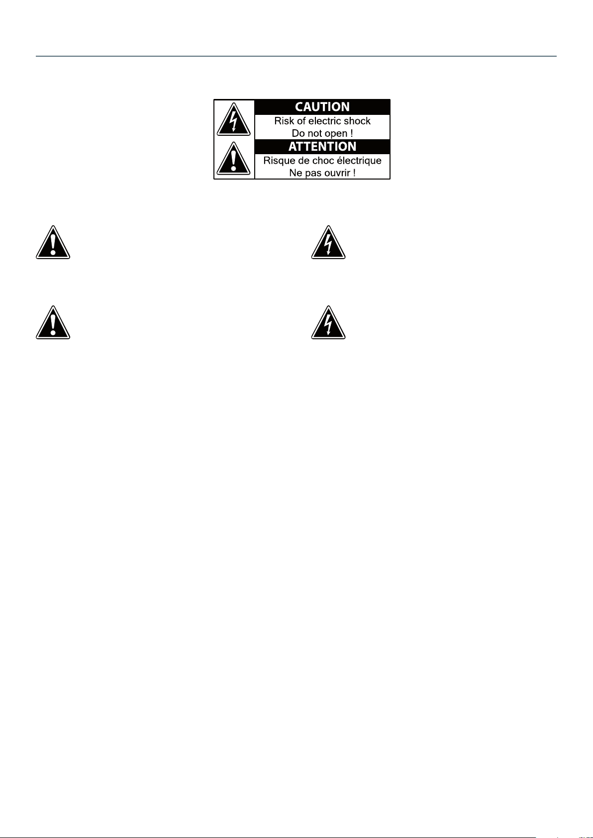
Safety Instructions
CAUTION: TO REDUCE THE RISK OF
ELECTRIC SHOCK, DO NOT REMOVE THE
COVER. NO USER SERVICEABLE PARTS
INSIDE. REFER SERVICING TO QUALIFIED
SERVICE PERSONNEL.
The exclamation point within an
equilateral triangle is intended to alert
the user to the presence of important
operating and maintenance (servicing)
instructions in the literature
accompanying the appliance.
■ Read Instructions - All the safety and operating
instructions should be read before the appliance is
operated.
■ Retain Instructions - The safety and operating
instructions should be retained for future reference.
■ Heed Warnings - All warnings on the appliance in the
operating instructions should be adhered to.
■ Follow Instructions - All operating and user instructions
should be followed.
■ Water and Moisture - The appliance should not be used
near water; for example, near a fountain, or submitted to
direct water exposure.
■ The apparatus shall not be exposed to dripping or
splashing liquids and no objects lled with liquids, such
as bottles, shall be placed on the apparatus. Do not
touch the appliance with wet hands. Do not handle the
appliance or power cord with wet or damp hands. If water
or any other liquid enters the appliance cabinet, take it to
qualied service personnel for inspection.
■ Cleaning - The appliance should be cleaned only as
recommended by the manufacturer. From time to time
you should wipe o the front and side panels and the
enclosure with a soft cloth. Do not use rough material,
thinners, alcohol or other chemical solvents or cloths since
this may damage the nish or remove the panel lettering.
■ Ventilation - The appliance should be situated so that
its location or position does not interfere with its proper
ventilation. Place the unit in a well-ventilated location,
leaving at least 5 cm (2 inches) of clearance on front, side
and rear of unit for air ow. If ventilation is blocked, the
unit may overheat and malfunction.
WARNING: TO REDUCE THE RISK OF FIRE
OR ELECTRIC SHOCK, DO NOT EXPOSE THIS
APPLIANCE TO RAIN OR MOISTURE.
The lightning ash with arrowhead symbol,
within an equilateral triangle, is intended to
alert the user to the presence of uninsulated
“dangerous
voltage” within the product’s enclosure
that may be of sucient magnitude to
constitute a risk of electric shock to persons.
■ Heat - The appliance should be situated away from
heat sources such as radiators or heating systems.
■ Power Cord Protection - Power supply cords should
be routed so that they are not likely to be walked on or
pinched by items placed upon or against them, paying
particular attention to cords at plugs, receptacles, and the
point where they exit from the appliance.
■ Power Sources - The appliance should be connected
to a power supply only of the type described in the
operating instructions or as marked on the appliance.
■ Attachments / Options - Only use attachments/options
specied by the manufacturer.
■ Object and Liquid Entry - Care should be taken so that
objects do not fall and liquids are not spilled into the
enclosure through the openings.
■ Servicing - The user should not attempt to service
the appliance beyond that described in the operating
instructions. All other servicing should be referred to
qualied service personnel.
■ Damage Requiring Service - The appliance should
be serviced by qualied service personnel when: A.
The power supply cord or the inlet has been damaged;
B. Objects have fallen, liquid has been spilled into the
appliance; C. The appliance has been exposed to rain; or
D. The appliance does not appear to operate normally;
or E. The appliance has been dropped or the enclosure is
damaged.
■ The equipment shall be used at a maximum ambient
temperature of 50° C / 140° F.
3
Page 4

Compliance information
Disposal of Waste Equipment by users in the European Union
This symbol on the product or its packaging indicates that this product must not be disposed of
with other waste. Instead, it is your responsibility to dispose of your waste equipment by handing it
over to a designated collection point for the recycling of waste electrical and electronic equipment.
The separate collection
and recycling of your waste equipment at the time of disposal will help conserve natural resources
and ensure that it is recycled in a manner that protects human health and the environment. For
more information about where you can drop o your waste equipment for recycling, please
contact your local city recycling oce or the dealer from whom you purchased the product.
EMC (Electromagnetic Compliance)
This model GigaCore 14R complies with the following standards regulating interference and EMC:
• EN 55103-1, environment E2
• EN 55103-2, environment E2
CE Compliance (EMC and Safety)
Luminex is authorized to apply the CE mark on this compliant equipment thereby declaring
conformity to EMC Directive 2004/108/EC and Low Voltage Directive 2006/95/EC.
4
Page 5

Warranty information
Limited warranty
Unless otherwise stated, your product is covered by a two (2) years parts and labor limited warranty. It is the owner’s
responsibility to furnish receipts or invoices for verication of purchase, date, and dealer or distributor. If purchase date
cannot be provided, date of manufacture will be used to determine warranty period.
Returning under warranty
Any Product unit or parts returned to Luminex LCE must be packaged in a suitable manner to ensure the protection
of such product unit or parts, and such package shall be clearly and prominently marked to indicate that the package
contains returned product units or parts. Accompany all returned product units or parts with a written explanation of
the alleged problem or malfunction.
Freight
All shipping will be paid by the purchaser. Items under warranty shall have return shipping paid by the manufacturer
only in the European Union.
Under no circumstances will freight collect shipments be accepted. Prepaid shipping does not include rush expediting
such as air freight. Air freight can be sent customer collect in the European Union.
Warranty is void if the product is misused, damaged, modied in any way, or for unauthorized repairs or parts.
Registration
Use your favorite web browser, and visit http://www.luminex.be/support.php?show=registration
to register your product online.
By registering, you become eligible to receive the following:
■ Technical support information
■ Software update and upgrade notices
■ Hardware warranty information
In the box
1 x Gi gaCore 14R
1 x Quick Start Guide ( including warranty information and safety instructions).
5
Page 6

Description
Front panel
LED indication of switch status :
- OK
- PoE sourcing
- RlinkX*
- Power
10/100/1000Mbps
shielded Neutrik
Ethercon port
Front port status :
- PoE
- RlinkX
- Link speed
Rear port status :
- RlinkX
- Link speed
■ 10 x 10/100/1000Mbps shielded Neutrik Ethercon connector
■ 4 x LED for switch status
■ 3 x LED per port for Ethercon front port status
■ 2 x LED per port for Ethercon and ber rear port status
6
* : Available in a future rmware release
Page 7

Rear panel
SFP cages for
Mini-GBIC (SFP)
compliant transceiver
- IEC inlet
- Fuse holder
Redundant fans: In the unlikely
of a fan failure, the other fan
will switch to 100%, so one fan
can manage the cooling of the
unit. Fans run at a minimum of
30%
10/100/1000Mbps
shielded Neutrik
Ethercon port with
RLinkX and Link/Speed
LED.
Console port (serial)
Reset button
(Clip hole)
Backup power inputs :
- Main Power
- PoE Supply
■ 2 x 10/100/1000Mbps shielded Neutrik Ethercon connector
■ 2 x LED per port for Ethercon port status
■ 2 x SFP cage for Mini-Gbic compliant transceiver
■ 1 x Serial console port on RJ45
■ 1 x Mollex Micro-t 6 pin connector for backup power supply input
■ 1 x Mollex Micro-t 6 pin connector for backup PoE supply input
■ 2 x Redundant fan
■ 1 x IEC inlet + Fuse holder
■ 1 x Reset button (clip hole)
7
Page 8

Led indicators
The LED indicators of the GigaCore 14R include status, Poe, RlinkX, power, link/speed.
The following shows the LED indicators for the GigaCo re 14R along with an explanation of each indicator.
Switch LED Status Meaning
OK (General status LED) Green All OK
Unit is booting / Unit is ashing rmware / Unit is writing
Red blink
PoE LED O No PoE
Green Internal and external PoE supply OK
Orange Internal supply OK (no external supply available)
Red blink Error
RlinkX LED Available in a future release
Power LED O No Power
Green Internal and external power supply OK
Orange Internal power supply OK (no external supply available)
Red blink Error
Port LED Status Meaning
PoE LED On Sourcing
O Not sourcing
Blink Error
RlinkX LED SFP On Redundant port / link
Link SFP O No link
Green Gigabit connection
Orange 10/100 Mbps connection
Blink Activity
the ash memory.
8
Page 9

Installing Mini GBIC (SFP) transceivers
The GigaCore 14R comes with four SFP cages at the rear of the unit. These cages accept mini GBIC transceivers. Check
our web site for more information about available transceivers.
Insert the transceiver into the SFP cage.
1
Once properly engaged,
the transceiver can’t be removed
Bail wire delatch
Device shown with
dust cap and bail
wire delatch
Dust cap
Be aware of the insertion direction:
2
- Port 13 & 15 must have the bail wire
delatch on the top
- Port 14 & 16 must have the mini-GBIC
transceiver upside-down
Bail wire delatch
Bail wire delatch
Bail wire delatch
Open the bail wire delatch to disengage
3
and remove the mini-GBIC transceiver.
For any other model of mini-GBIC transceiver, please refer to the transceiver manual.
9
Page 10

Connecting the backup power supply
The GigaCore 14R comes with two backup power inlets at the rear. This inputs are meant to connect external power
supply units for both mains and Power Over Ethernet. This providing redundancy on power level.
Each power supply requires specic output voltage and pinout. It is not recommended to use dual output power supply
to feed the two backup power input, as both input requires a separate isolation.
Please respect the following pinout to connect external power supplies to the GigaCore 14R. Use the Luminex cable to
connect the GigaCore 14R to external power supplies.
6 6 55 4 4
Starting
3 2 23
Pin 15VDC / 2A 48VDC / 2.1A
1 Ground Ground
2 N.C +48VDC
3 +15V D C N.C
4 Ground Ground
5 N.C +48VDC
6 +15V D C N.C
1 1
The device operates with an AC voltage between 100V and 240VAC within a frequency range of 50Hz to 60Hz.
An IEC socket is located at the rear of the unit. Please use an IEC plug compliant cable to feed power to the unit.
Luminex recommends the use of a power cable, tted with a locking mechanism to ensure a reliable connection to the
device. Luminex also recommends to use power cable in accordance with the standards and the relevant authorities of
your country.
!!! WARNING: TO ENSURE A TOTAL PROTECTION, THIS EQUIPMENT MUST BE EARTHED !!!
Connect the power cable to the device, and connect the other side of the cable to the mains. It will take around 20
seconds for the switch to boot up. You’ll then be able to use it.
10
Page 11

Specications
Power Input Physical
100-240VAC - 50/60Hz
Power Input
Backup Power Input
Backup PoE Input
Power Consumption
Fuse 3.15A 250V Slow Blow Approvals
Environmental CE
Operating Temperature 0 to + 50°C EN 55103-1
Storage temperature -10 to +70°C EN 55103-2
Humidity 5 to 95 % RH
0.3A - 0.125A
1.8A - 0.75A with PoE Option
15VDC / 2A on Molex MicroFit 6 pin connector
48VDC / 2.1A on Molex
Micro-Fit 6 pin connector
Maximum 30W
Maximum 180W with PoE
option
Enclosure Metal Housing
Dimensions (W x D x H)
Packaging
Weight 2.5Kg
EN 60950-1
RoHS Compliance
482 x 204,3 x 44 mm
19” x 8.04” x 1.73”
520 x 235 x 50 mm
20.47” x 9.25” x 1.96”
P
P
P
P
P
Luminex LCE operates a policy of continuous development. Luminex LCE reserves the right to make changes and
improvements to any of the products described in this document above without prior notice. Specications are subject
to change without notice.
Connection to the web interface
■ Connect a computer to the switch
■ Set an IP address in the same range as the switch IP address.
■ Default GigaCore IP address is displayed at the rear of the unit. Set your computer with a compliant IP address (do not
use the same IP address ! )
■ Launch your favorite web browser
■ Type the IP address of the switch in the address eld.
■ Enter admin in the login eld. Leave the password eld blank.
Additional documentation
All additional documenttion can be downloaded from our web pages in the support section :
http://www.luminex.be
--> Support
11
Page 12

12
Berkennlaan 8A
3940 Hechtel Eksel
Belgium
tel: +32 11 812 189
info@luminex.Be
www..luminex.be
 Loading...