

Page 1
PART NUMBER:
LU 01 00058 YZA - GigaCore 10
LU 01 00058-POE YZA - GigaCore 10 with PoE
Gigabit Ethernet Switch
QUICK START GUIDE
The basic features for an easy set-up
Page 2

Page intentionally left blank
Page 3
WELCOME TO YOUR GIGACORE 10!
Congratulations, you managed to buy some of the latest high-end technologies in the entertainment industry.
Now let’s rock and roll! Read this quick start guide carefully to get familiar with the basic features of the GigaCore 10.
1. MOUNTING THE DEVICE
GigaCore 10 is a device that can be mounted in a truss as well as in a rack. Please read the following instructions to make sure the device is
mounted and secured correctly.
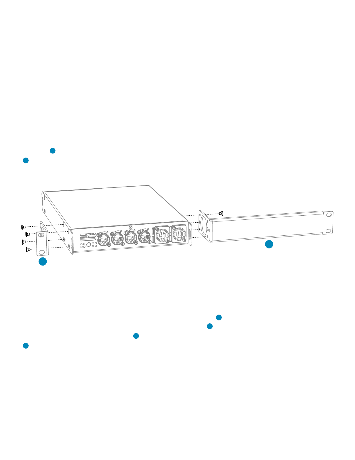
1.1 RACK MOUNT
In case you want to mount your GigaCore 10 in a standard 19 inch rack, you first have to attach the included mounting ears. Connect the
longest ear (A) to the right hand side of the device with 4 out of the 8 screws located on the sides of the product. Attach the shorter ear
(B) to the left hand side with the 4 screws that are left. If needed, you can obviously reverse the mounting ears.
A
B
(Illustration 1: rack mounting)
1.2 RACK MOUNT TWO DEVICES
In case you want to mount two GigaCore 10 devices in a standard 19 inch rack, you have the ability to mount the two devices together.
In space saving way that the two devices will only consume a single row in your 19 inch rack.
You first have to attach the included shortest mounting ears. Connect the shortest ear ( ) to the left hand side of the first device with 4 out
of the 8 screws located on the side of the product. Attach the other shortest ear (D), delivered with the second device, to the right hand
side with 4 of the 8 screws. Use a pair of couplers (E) to connect the two devices in the middle on the frontside. Again use a pair of couplers
(E), delivered with the second device, to connect the devices at the rear. Each pair of couplers must be mounted with 2 screws.
C
Page 4

E
D
E
C
1.3 TRUSS MOUNT
To mount the GigaCore 10 in a truss, you have to attach a M10 clamp ( F ) to one of the two inserts ( i1 or i2 ). After that, you can mount
the clamp to the truss bars. Please also secure the device by attaching a safety line directly to the truss bars as well ( G ).
This side down when using i
(Illustration 2: truss mounting)
1
i1
F
G
Page 5

2. POWER UP THE DEVICE
Power-up the device with a power cable with Neutrik powerCON TRUE1 connection ( 1 ) (please contact your local dealer if you don’t have
a suitable power cable on hand). The device will automatically switch on. To shut it down after use, just un-plug the power cable again.
(Illustration 3: power connection)
1
1 - Power In: Power input on Neutrik powerCON TRUE1
After connecting a power cable correctly, by default the power LED indicator on the front panel will light up in green.
3. LED INDICATORS
(Table 1: LED colors)
Find below the signification for every switch’s LED.
Switch LED Colour Description
Power (General status LED) Green All OK
Green blink Unit is writing to the ash. Do not disconnect power
Orange Temperature warning
Red blink Temperature or Fan error
Red/Green blink The unit is ashing new rmware. Do not disconnect power
PoE LED (GigaCore 10 with PoE only) Green Internal PoE supply OK. PoE functionality OK
Red blink PoE supply or PoE functionality error
RLinkX LED Green RLinkX is active
Port LED Status Description
Link O No link
Green Gigabit connection
Orange 10/100 Mbps connection
Blink Activity
Page 6

By pressing the mode button, you can select what info to display on the ports’ LEDs.
State Mode LED Port Mode LED Description
Groups White Group colour The LED colour indicates the group assignation of the port
RLinkX Blue Blue Indicates a redundant port
MultiLinkX Magenta Magenta MultiLinkX is enabled
White MultiLinkX is active
PoE Yellow Yellow PoE is activated on this port
Orange Port is sourcing a device
Red Error on PoE
Dark Mode O O All port’s LEDs are switched o. Switch’s status LEDs remain
available. Ideal to reduce light emitted by the switch
3. CONNECT TO THE WEB INTERFACE
- Connect a computer to the switch with a network cable
- Default GigaCore ‘s IP address is displayed at the rear of the unit. Set your computer with an IP address within the same
subnet (do not use the same IP address!)
- Launch your favorite web browser
- Type the following IP address of the switch in the address field
- Enter admin in the login field. Leave the password field blank.
4. RESET
Sometimes it can come in handy to reset the device. To do that, press and hold the mode button for 10 seconds. Once the four
LED indicator blinks red, release the button. This will reset all settings to default. User profiles will be preserved though.
Page 7

Page intentionally left blank
Page 8

Package contents
(Please contact your local dealer in case of missing parts)
1x
GigaCore 10
(part no. LU 01 00058)
Luminex Network Intelligence - Slamstraat 13 - B-3600 Genk, Belgium - +32 11 812 189 - support@luminex.be
PowerCON TRUE1 connector
1x
(Neutrik NAC3FX-W)
2x
Rack mounting
brackets + 2 couplers
Mounting screws
2x
for couplers
1x
Quick start guide
 Loading...