

Page 1

Luminex® FLEXMAP 3D
Hardware User Manual
For research use only. Not for use in
diagnostic procedures.
®
Page 2

©
Luminex Corporation, 2012. All rights reserved. No part of this publication may be
reproduced, transmitted, transcribed, or translated into any language or computer language,
in any form or by any means without prior express, written consent of Luminex Corporation.
LUMINEX CORPORATION
12212 Technology Boulevard
Austin, Texas 78727-6115
U.S.A.
Voice: (512) 219-8020
Fax: (512) 219-5195
Luminex® FLEXMAP 3D® Hardware User Manual (RUO)
PN 89-00002-00-410 Rev A
August 2012
European Union (EU)
Authorized
Representative:
Luminex B.V.
Kombraak 15
4906 CR Oosterhout
The Netherlands
Luminex Corporation (Luminex) reserves the right to modify its products and services at any
time. This guide is subject to change without notice. Although prepared to ensure accuracy,
Luminex assumes no liability for errors or omissions, or for any damages resulting from the
application or use of this information.
The following are trademarks of Luminex Corporation: Luminex®,
xMAP®, xPONENT®,
FLEXMAP 3D®.
All other trademarks, including ProClin®, Cheminert®, Windows® Pentium® and Dell® are
trademarks of their respective companies.
Luminex® FLEXMAP 3D® Hardware User Manual
ii
For research use only. Not for use
in diagnostic procedures.
Page 3

Standard Terms and Conditions for Use of Instrument
Product
By opening the packaging containing this instrument product ("Product") or by using
such Product in any manner, you are consenting and agreeing to be bound by the
following terms and conditions. You are also agreeing that the following terms and
conditions constitute a legally valid and binding contract that is enforceable against
you. If you do not agree to all of the terms and conditions set forth below, you must
promptly return the Product for a full refund prior to using them in any manner.
1. Acceptance
ALL SALES ARE SUBJECT TO AND EXPRESSLY CONDITIONED UPON THE TERMS
AND CONDITIONS CONTAINED HEREIN, AND UPON BUYER'S ASSENT THERETO. NO
VARIATION OF THESE TERMS AND CONDITIONS SHALL BE BINDING UPON LUMINEX
CORPORATION ("LUMINEX") UNLESS AGREED TO IN WRITING AND SIGNED BY AN
AUTHORIZED REPRESENTATIVE OF LUMINEX.
For purposes of this agreement, "Seller" shall mean either Luminex, if the Product is
purchased directly from Luminex, or a Luminex authorized reseller. Buyer, by accepting the
Product, shall be deemed to have assented to the terms and conditions set forth herein,
notwithstanding any terms contained in any prior or later communications from Buyer and
whether or not Seller shall specifically or expressly object to any such terms.
2. Warranties
THIS WARRANTY IS APPLICABLE FOR PARTS AND SERVICE FOR LUMINEX
INSTRUMENTS PURCHASED DIRECTLY FROM LUMINEX TO BUYER AND ONLY TO
THE EXTENT SUCH INSTRUMENTS ARE LOCATED IN NORTH AMERICA AND THE
COUNTRIES THAT COMPRISE THE EUROPEAN UNION. LUMINEX MAKES NO
WARRANTY, EITHER EXPRESS OR IMPLIED, WITH RESPECT TO PRODUCTS SOLD,
DISTRIBUTED, LOCATED OR USED OUTSIDE OF NORTH AMERICA OR THE
COUNTRIES COMPRISING THE EUROPEAN UNION. PRODUCTS SOLD OUTSIDE OF
NORTH AMERICA OR THE COUNTRIES COMPRISING THE EUROPEAN UNION ARE
SOLD ONLY ON AN "AS IS, WHERE IS" BASIS. NOTWITHSTANDING THE FOREGOING,
LUMINEX SHALL PROVIDE BUYER A WARRANTY ON FIELD SERVICE PARTS
PROCURED FROM LUMINEX FOR MAINTENANCE OF LUMINEX INSTRUMENTS IN ALL
COUNTRIES IN THE WORLD AND PER THE TERMS AND CONDITIONS HEREIN. TO
THE EXTENT THAT THE FOREGOING DISCLAIMERS ARE INVALID OR
UNENFORCEABLE UNDER THE LAWS OF ANY JURISDICTION, THE WARRANTY,
DISCLAIMER, LIMITATION OF LIABILITY AND OTHER PROVISIONS SET FORTH BELOW
SHALL THEREUPON BE EFFECTIVE TO THE FULLEST EXTENT PERMITTED BY
APPLICABLE LAW.
Notwithstanding Buyer's acceptance thereof, if Product is purchased directly from Luminex,
Luminex warrants that for a period of twelve (12) months from date of delivery that the
Product shall conform in all material respects with the Product Specifications provided by
Luminex with the Product. The warranty provided herein specifically excludes any software or
iii
Page 4

hardware not provided by Luminex. If Product is purchased from a Luminex authorized
reseller, any warranty obligations shall be provided in writing directly by such Luminex
authorized reseller to Buyer. THIS WARRANTY IS EXCLUSIVE AND LUMINEX MAKES NO
OTHER WARRANTY, EXPRESS OR IMPLIED, INCLUDING, WITHOUT LIMITATION, ANY
IMPLIED WARRANTY OF MERCHANTABILITY, FITNESS FOR A PARTICULAR
PURPOSE, OR NON-INFRINGEMENT. Seller's warranties made in connection with this sale
shall not be effective if Seller has determined, in its sole discretion, that Buyer has misused
the Product in any manner, has failed to use the Product in accordance with industry
standards or practices, or has failed to use the Product in accordance with instructions, if any,
furnished by Seller.
BUYER'S EXCLUSIVE REMEDY WITH RESPECT TO PRODUCT PROVED TO SELLER'S
SATISFACTION TO BE DEFECTIVE OR NONCONFORMING, SHALL BE, REPAIR OR
REPLACEMENT OF SUCH PRODUCTS WITHOUT CHARGE OR REFUND OF THE
PURCHASE PRICE, IN SELLER'S SOLE DISCRETION, UPON THE RETURN OF SUCH
PRODUCTS IN ACCORDANCE WITH SELLER'S INSTRUCTIONS BELOW. NEITHER
SELLER NOR LUMINEX NOR ANY OF ITS AFFILIATES SHALL IN ANY EVENT BE LIABLE
FOR INCIDENTAL, CONSEQUENTIAL OR SPECIAL DAMAGES OF ANY KIND
RESULTING FROM ANY USE OR FAILURE OF THE PRODUCT, EVEN IF SELLER OR
LUMINEX OR ITS AFFILIATE HAS BEEN ADVISED OF THE POSSIBILITY OF SUCH
DAMAGES, INCLUDING, WITHOUT LIMITATION, LIABILITY FOR LOSS OF WORK IN
PROGRESS, DOWN TIME, LOSS OF REVENUE OR PROFITS, FAILURE TO REALIZE
SAVINGS, LOSS OF PRODUCTS OF BUYER OR OTHER USE OR ANY LIABILITY OF
BUYER TO A THIRD PARTY ON ACCOUNT OF SUCH LOSS, OR FOR ANY LABOR OR
ANY OTHER EXPENSE, DAMAGE OR LOSS OCCASIONED BY SUCH PRODUCT,
INCLUDING PERSONAL INJURY OR PROPERTY DAMAGE UNLESS SUCH PERSONAL
INJURY OR PROPERTY DAMAGE IS CAUSED BY SELLER'S GROSS NEGLIGENCE.
In the event that Product is located outside of North America or the European Union and fails
to conform to the warranty set forth herein, during the warranty period: (i) Buyer shall notify
Luminex in a timely manner in writing that such Product failed to conform and shall furnish a
detailed explanation of any alleged nonconformity; (ii) Buyer, at its expense, will contact
either Luminex or a Luminex trained service engineer to assess the issue and identify the
defective FS-PART; and (iii) at Luminex's option and election, Buyer shall either return such
nonconforming Product to Luminex's manufacturing facility or destroy such Product and
provide Luminex with written certification of destruction. In the event that an FS-PART is
returned to Luminex's manufacturing facility, Luminex may analyze such FS-PART for
defects. In the event that Luminex determines that such FS-PART is not defective, the FSPART shall be shipped to Buyer and Buyer shall be responsible for the payment for such FSPART and related shipping charges. In the event that Luminex determines that such FSPART is defective, Luminex shall be responsible for the payment for such FS-PART and
related shipping charges. Except as expressly provided herein, Buyer shall not have the right
to return a Product to Luminex without Luminex's prior written consent.
3. Buyer's Use of Product
Buyer shall not use this Product for any commercial purpose, including without
limitation, performance of testing services, unless expressly agreed to in writing by
Luminex or as specifically authorized by Luminex through a Luminex distributor.
Buyer agrees that no rights or licenses under Luminex's patents shall be implied from the
sale of the Product, except as expressly provided herein or as specifically agreed to in writing
by Luminex, and Buyer does not receive any right under Luminex's patent rights hereunder.
Buyer acknowledges and agrees that the Product is sold and licensed only for use with
Luminex® FLEXMAP 3D® Hardware User Manual
iv
For research use only. Not for use
in diagnostic procedures.
Page 5

Luminex's laser based fluorescent analytical test instrumentation. Buyer further
acknowledges that the Product has not received approval from the United States Food and
Drug Administration or other federal, state or local regulatory agencies and has not been
tested by Seller or Luminex for safety or efficacy in food, drug, medical device, cosmetic,
commercial or any other use, unless otherwise stated on the Product label or in Seller's
technical specifications or material data sheets furnished to Buyer. Buyer expressly
represents and warrants to Seller that Buyer will use the Product in accordance with the
Product label, if applicable, and will properly test and use any Product in accordance with the
practices of a reasonable person who is an expert in the field and in strict compliance with the
United States Food and Drug Administration and all applicable domestic and international
laws and regulations, now and hereinafter enacted.
BUYER HEREBY GRANTS TO LUMINEX A NONEXCLUSIVE, WORLDWIDE,
UNRESTRICTED, ROYALTY-FREE, FULLY PAID-UP LICENSE, WITH THE RIGHT TO
GRANT AND AUTHORIZE SUBLICENSES, UNDER ANY AND ALL PATENT RIGHTS IN
INVENTIONS COMPRISING MODIFICATIONS, EXTENSIONS, OR ENHANCEMENTS
MADE BY BUYER TO THE PRODUCT OR TO THE MANUFACTURE OR USE OF THE
PRODUCT ("IMPROVEMENT PATENTS"), TO MAKE, HAVE MADE, USE, IMPORT,
OFFER FOR SALE OR SELL ANY AND ALL OF THE PRODUCT; EXPLOIT ANY AND ALL
METHODS OR PROCESSES; AND OTHERWISE EXPLOIT IMPROVEMENT PATENTS
FOR ALL PURPOSES. NOTWITHSTANDING THE FOREGOING, "IMPROVEMENT
PATENTS" SPECIFICALLY EXCLUDES PATENT CLAIMS CONCEIVED AND REDUCED
TO PRACTICE BY BUYER CONSISTING OF METHODS OF SAMPLE PREPARATION,
METHODS OF CONJUGATING PRODUCT TO ANALYTES, THE COMPOSITION OF
MATTER OF THE SPECIFIC CHEMISTRIES OF THE ASSAYS DEVELOPED BY BUYER
AND METHODS OF PERFORMING THE ASSAYS (I.E., THE PROTOCOL FOR THE
ASSAY).
Buyer has the responsibility and hereby expressly assumes the risk to verify the hazards and
to conduct any further research necessary to learn the hazards involved in using the Product.
Buyer also has the duty to warn Buyer's customers, employees, agents, assigns, officers,
successors and any auxiliary or third party personnel (such as freight handlers, etc.) of any
and all risks involved in using or handling the Product. Buyer agrees to comply with
instructions, if any, furnished by Seller or Luminex relating to the use of the Product and to
not misuse the Product in any manner. Buyer shall not reverse engineer, decompile,
disassemble or modify the Product. Buyer acknowledges that Luminex retains ownership of
all patents, trademarks, trade secrets and other proprietary rights relating to or residing in the
Product and Buyer receives no rights to such intellectual property rights by virtue of its
purchase of Product other than as expressly set forth herein. Buyer shall have no right to use
any trademarks owned or licensed to Luminex without the express written permission of
Luminex.
4. Buyer's Representations, Release and Indemnity
Buyer represents and warrants that it shall use the Product in accordance with Paragraph 3,
"Buyer's Use of Product," and that any such use of the Product will not violate any law,
regulation, judicial order or injunction. Buyer agrees to release, discharge, disclaim and
renounce any and all claims, demands, actions, causes of action and/or suits in law or equity,
now existing or hereafter arising, whether known or unknown, against Seller and Luminex,
and their respective officers, directors, employees, agents, successors and assigns
(collectively the "Released Parties"), with respect to the use of the Product. Buyer agrees to
indemnify and hold harmless the Released Parties from and against any suits, losses, claims,
demands, liabilities, costs and expenses (including attorney, accounting, expert witness, and
For research use only. Not for use in diagnostic procedures.
v
Page 6

consulting fees) that any of the Released Parties may sustain or incur as a result of any claim
against such Released Party based upon negligence, breach of warranty, strict liability in tort,
contract or any other theory of law or equity arising out of, directly or indirectly, the use of the
Product or by reason of Buyer's failure to perform its obligations contained herein. Buyer shall
fully cooperate with the Released Parties in the investigation and determination of the cause
of any accident involving the Product which results in personal injury or property damage and
shall make available to the Released Parties all statements, reports, recordings, and tests
made by Buyer or made available to Buyer by others.
5. Patent Disclaimer
Neither Seller nor Luminex warrants that the use or sale of the Product will not infringe the
claims of any United States or other patents covering the Product itself or the use thereof in
combination with other products or in the operation of any process.
89-30000-00-186 (Rev C.)
Luminex® FLEXMAP 3D®
vi
Hardware User Manual
For research use only. Not for use
in diagnostic procedures.
Page 7

Table of Contents
Chapter 1 Safety ..................................................................................................................1
Description ...................................................................................................................................................1
Warnings and Notes ....................................................................................................................................1
Symbols .......................................................................................................................................................2
Testing and Certification ..............................................................................................................................2
Safety Precautions .......................................................................................................................................3
General
Electromagnetic Compatibility ...............................................................................................................3
Lasers ....................................................................................................................................................4
Fluidics ..................................................................................................................................................5
Biological Samples ................................................................................................................................5
Mechanical Components .......................................................................................................................6
Swivel Base ...........................................................................................................................................6
Indicator Lights ......................................................................................................................................6
Electrical Components ..........................................................................................................................6
Heat .......................................................................................................................................................7
Decontamination Procedure ........................................................................................................................7
Installation of Instrument ..............................................................................................................................8
Disposal of Instrument .................................................................................................................................9
..................................................................................................................................................3
Chapter 2 Technical Overview .........................................................................................11
How the FLEXMAP 3D System Operates .................................................................................................11
Subsystems ...............................................................................................................................................12
Electronics ...........................................................................................................................................12
Fluidics ................................................................................................................................................13
Mechanics ...........................................................................................................................................17
Optics ..................................................................................................................................................19
System Components .................................................................................................................................19
Luminex® xPONENT® Software .........................................................................................................19
Reagents .............................................................................................................................................19
Luminex® FLEXMAP 3D® Hardware ..................................................................................................21
Recommended Additional Equipment .......................................................................................................21
Uninterruptible Power Supply (UPS) or Surge Protector .....................................................................21
Printer ..................................................................................................................................................22
Barcode Labels ...................................................................................................................................22
Vortex ..................................................................................................................................................22
Bath Sonicator .....................................................................................................................................22
Specifications and Limitations ...................................................................................................................22
General ................................................................................................................................................22
Electronics ...........................................................................................................................................24
Optics ..................................................................................................................................................24
Fluidics ................................................................................................................................................24
Microspheres .......................................................................................................................................24
Microtiter Plates ...................................................................................................................................25
vii
Page 8

Chapter 3 Maintenance and Cleaning .............................................................................27
General Maintenance Precautions ............................................................................................................27
Daily Maintenance .....................................................................................................................................27
Initializing the Luminex® FLEXMAP 3D® Instrument ..........................................................................28
Warming Up the Luminex® FLEXMAP 3D® Instrument ......................................................................28
Maintaining Fluids ...............................................................................................................................28
Shutting Down the Luminex® FLEXMAP 3D® Instrument ...................................................................29
Weekly Maintenance .................................................................................................................................29
Running Weekly Maintenance .............................................................................................................29
Removing Clogs ..................................................................................................................................30
Cleaning the Sample Probe ................................................................................................................30
Calibrating the Luminex® FLEXMAP 3D® System ..............................................................................31
Visually Inspect the Luminex® FLEXMAP 3D® Instrument .................................................................31
Monthly Maintenance .................................................................................................................................32
Semi-Annual Maintenance .........................................................................................................................32
Replacing the Syringe Teflon Seals ....................................................................................................32
Replacing the HEPA Air Filter .............................................................................................................34
Cleaning the Ventilation Filters ............................................................................................................35
Annual Maintenance ..................................................................................................................................37
Storing the Luminex® FLEXMAP 3D® Instrument .....................................................................................38
Storing the Luminex® FLEXMAP 3D® Instrument ...............................................................................38
Preparing the Luminex® FLEXMAP 3D® Instrument for Use After Storage ........................................39
Replacing Fuses ........................................................................................................................................39
Maintenance Logs .....................................................................................................................................40
Chapter 4 Troubleshooting ..............................................................................................43
Overview ....................................................................................................................................................43
Power Supply Problems ............................................................................................................................44
Communication Problems ..........................................................................................................................44
Clogs ..........................................................................................................................................................45
Pressurization Problems ............................................................................................................................45
Fluid Leaks ................................................................................................................................................46
Sample Probe Problems ............................................................................................................................46
Calibration Problems .................................................................................................................................47
Verification Problems .................................................................................................................................48
Acquisition Problems .................................................................................................................................49
Bead Detail Irregularities ...........................................................................................................................50
Appendix A Shipping ........................................................................................................53
Shipping .....................................................................................................................................................53
Draining the Reservoir ...............................................................................................................................53
Shipment Checklist ....................................................................................................................................54
Appendix B Installation ....................................................................................................57
Installation of the Luminex® FLEXMAP 3D®.............................................................................................57
Appendix C Part Numbers ................................................................................................65
Luminex® FLEXMAP 3D® Hardware User Manual
viii
For research use only. Not for use
in diagnostic procedures.
Page 9

Appendix D FLEXMAP 3D® Probe Height Adjustment Tool .........................................67
Appendix E Maintenance Schedule .................................................................................71
Short Term Maintenance Schedule ...........................................................................................................71
Long Term Maintenance Schedule ............................................................................................................73
For research use only. Not for use in diagnostic procedures.
Table of Contents
ix
Page 10

Luminex® FLEXMAP 3D® Hardware User Manual
x
For research use only. Not for use
in diagnostic procedures.
Page 11

Chapter 1: Safety
Become familiar with the information in this chapter before using the equipment. Do not
perform procedures on your system that are not specifically contained in this manual, unless
you are directed to do so by Luminex Technical Support.
Description
The Luminex® FLEXMAP 3D® system is a life science research multiplex test system
intended to measure and sort multiple signals generated in an assay from a biological
sample. The FLEXMAP 3D system is for research use only and is not for use in diagnostic
procedures. The FLEXMAP 3D system is for laboratory and professional use only.
Warnings and Notes
The following informational notes and warnings appear as necessary in this manual.
NOTE: This message is used to provide general helpful information. No
safety or performance issues are involved.
CAUTION: This message is used in cases where the hazard is minor or only
a potential hazard is present. Failure to comply with the caution
may result in hazardous conditions.
WARNING: This message is used in cases where danger to the operator or
to the performance of the instrument is present. Failure to
comply with the warning may result in incorrect performance,
instrument failure, invalid results, or hazard to the operator.
DANGER: This message is used in cases where significant risk of serious
injury or death is present.
1
Page 12
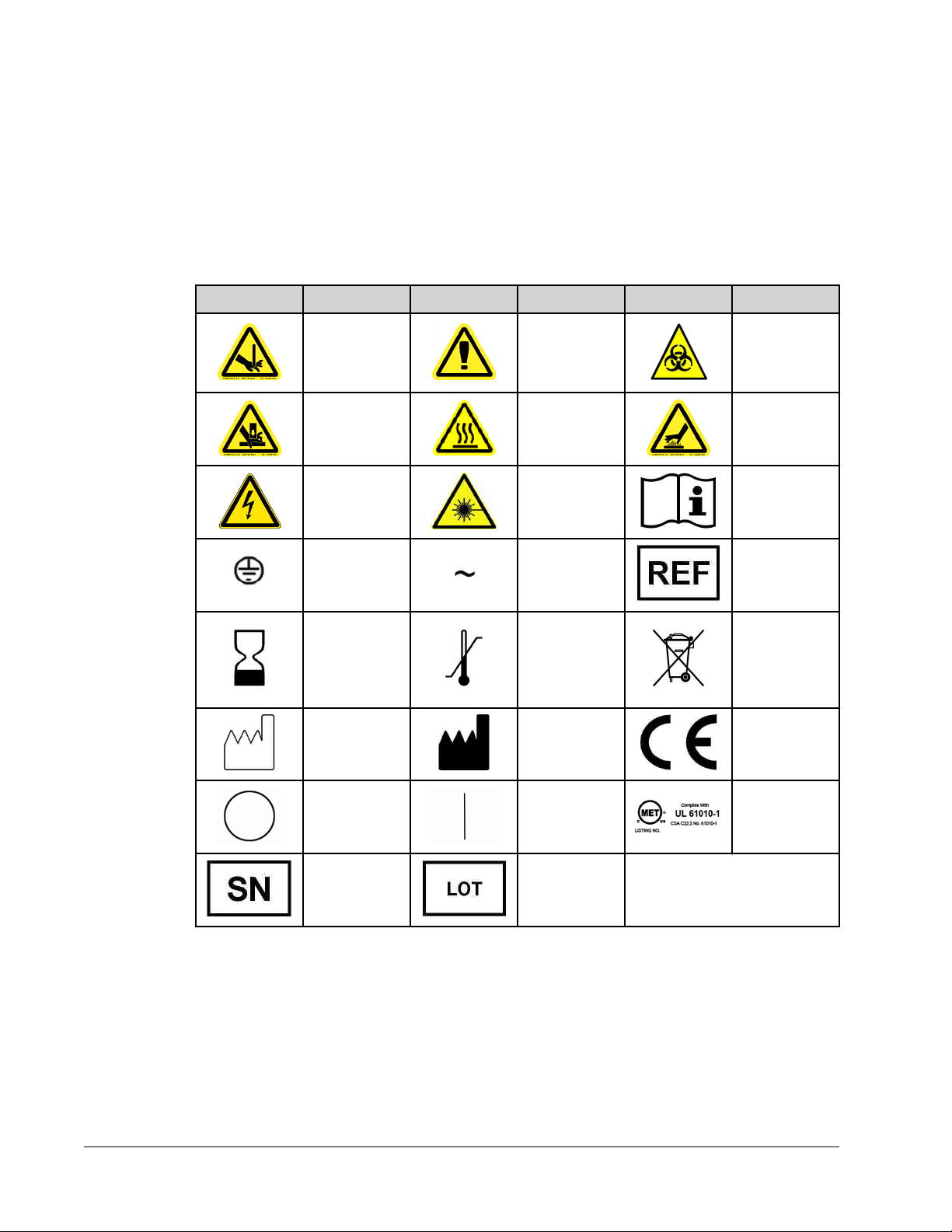
Symbols
You may encounter these symbols during the use and operation of the
Luminex® FLEXMAP
3D® system. They represent warnings, conditions, identifications, instructions, and regulatory
agencies. Warning symbols are further explained in the Safety Precautions section.
Symbol Description Symbol Description Symbol Description
Puncture/Pinch
Point Warning
Hand Crush/
Cut/Force
From Above
Caution, Risk
of Electric
Shock
Protective
ground
Use By
Expiration Date
General
Warning,
Caution, Risk
of Danger
Heat/Hot
Surface
Warning
Warning, Laser
Beam
Alternating
current (AC)
Temperature
Limitation
Warning,
Biological
Hazard
Burn Hazard/
Hot Surface
Consult
Instructions for
Use
Catalog
Number
Waste
Electrical and
Electronic
Equipment
(WEEE)
Date of
Manufacture
Off (Power) On (Power) MET Mark
Serial Number Batch Code
Testing and Certification
The Luminex® FLEXMAP 3D®
Luminex® FLEXMAP 3D® Hardware User Manual
2
system has been tested by MET.
Manufacturer European
Union
Conformity
For research use only. Not for use
in diagnostic procedures.
Page 13
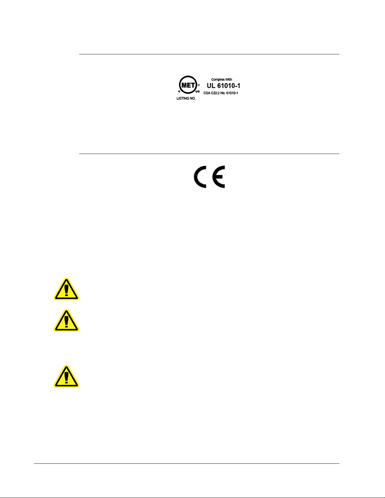
FIGURE 1.
In addition, Luminex FLEXMAP 3D complies with European Union (EU) safety requirements
and therefore may be marketed in the Europe Single Market. The following European Union
compliance label appears on the back of the FLEXMAP 3D instrument.
MET Mark
FIGURE 2.
European Union Compliance Label
Safety Precautions
Read the following safety information before using the
This instrument contains electrical, mechanical, and laser components that, if handled
improperly, are potentially harmful. In addition, biological hazards may be present during
system operation. Therefore, Luminex recommends that all system users become familiar
with the specific safety advisories below in addition to adhering to standard laboratory safety
practices.
NOTE: In any situation in which you encounter this symbol, consult this
manual or other Luminex documentation to determine the nature of
the potential hazard and any necessary actions you must take.
CAUTION: The protection provided by the equipment can be impaired or the
Luminex® FLEXMAP 3D® instrument.
warranty voided if the
manner not specified by the instructions or by Luminex
Corporation.
FLEXMAP 3D® system is used in a
General
CAUTION: Keep access doors closed during normal operation.
Always observe standard laboratory safety practices.
Electromagnetic Compatibility
The Luminex®
described in IEC/EN 61326-1. The electromagnetic environment should be evaluated prior to
operation.
For research use only. Not for use in diagnostic procedures.
FLEXMAP 3D® system complies with the emission and immunity requirements
Safety
3
Page 14
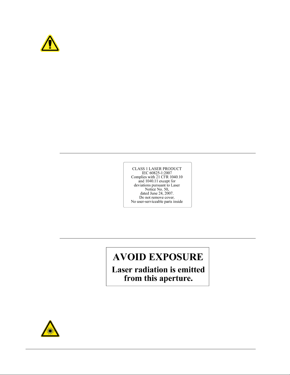
Lasers
The Luminex® FLEXMAP 3D® instrument is classified under FDA 21 CFR 1040.10 and
1040.11 as a Class I laser product consisting of two Class IIIb lasers within the instrument.
The optional bar code reader is a Class II stand-alone component. In accordance with IEC
60825-1, the instrument is classified as Class 1, containing two Class 3b lasers. The optional
bar code reader is a Class II stand-alone component. The
60825-1 and 21 CFR 1040.10 and 1040.11 except for deviations pursuant to Laser Notice
No. 50, dated June 24, 2007.
The following label appears on the back of the FLEXMAP 3D® instrument.
WARNING: Do not use this device in close proximity to sources of strong
electromagnetic radiation, for example, unshielded intentional
RF sources, as these may interfere with proper operation
WARNING: Always handle the FLEXMAP 3D® system according to Luminex
instructions to avoid any possible interference from its
electromagnetic fields.
FLEXMAP 3D® complies with IEC
FIGURE 3.
The following label appears above the laser apertures located inside the optics enclosure
inside the
FIGURE 4.
Laser Warning Label
FLEXMAP 3D® instrument.
Avoid Exposure Label
All Class 3b laser apertures are located within the FLEXMAP 3D® instrument and are
contained within a protective housing, accessible only to trained field service technicians.
When performing routine maintenance, turn power to the system off and disconnect the
power cord.
Luminex® FLEXMAP 3D®
4
DANGER: Do not, under any circumstances, remove the FLEXMAP 3D
instrument cover. Use of controls or adjustments or performance
Hardware User Manual
For research use only. Not for use
in diagnostic procedures.
®
Page 15

The bar code reader laser presents a potential hazard to eyesight.
Fluidics
This instrument contains fluids. In the event of a fluid leak, turn off all power to the system
and disconnect all power cords. The on/off switch is not a method of disconnection; the
power cord must be removed from the outlet. Contact Luminex Technical Support for further
information.
Optimally, the waste line should be routed to a laboratory drain. If you use a waste container,
monitor waste fluid levels periodically. The volume of the waste container should be at least
as large as the volume of the sheath container. Do not allow the waste fluid container to
overflow. Empty the waste fluid container each time you replace or fill the sheath fluid
container. Place the waste fluid container at least three feet below the surface on which the
Luminex® FLEXMAP 3D® instrument rests. Do not place the waste fluid container on top of
the instrument. Do not move the waste line vertically while the
running, and make certain the waste container is properly vented. Contact Luminex Technical
Support before relocating the waste fluid container or rerouting the waste line.
of procedures other than those specified in this manual can result
in hazardous radiation exposure.
DANGER: Do not stare into the barcode reader beam or shine it into other
people’s eyes.
DANGER: Do not operate the instrument in the presence of leaking fluid.
FLEXMAP 3D® instrument is
CAUTION: Reagents may contain sodium azide as a preservative. Sodium
azide is toxic and may also react with lead and copper plumbing
to form highly explosive metal azides. On disposal, flush drains
with a generous amount of cold water to prevent azide build-up.
Consult the manual guideline “Safety Management No. CDC-22,
Decontamination of Laboratory Sink Drains to remove Azide
salts” (Centers for Disease Control, Atlanta, Georgia, April 30,
1976).
Biological Samples
Human and animal samples may contain biohazardous infectious agents.
Where exposure to potentially biohazardous material exists, follow
appropriate biosafety procedures and use personal protective equipment
(PPE). PPE includes gloves, gowns, laboratory coats, face shields or mask
and eye protection, respirators, and ventilation devices. Observe all local,
state, federal and country specific biohazard handling regulations when
disposing of biohazardous waste material.
For research use only. Not for use in diagnostic procedures.
Safety
5
Page 16
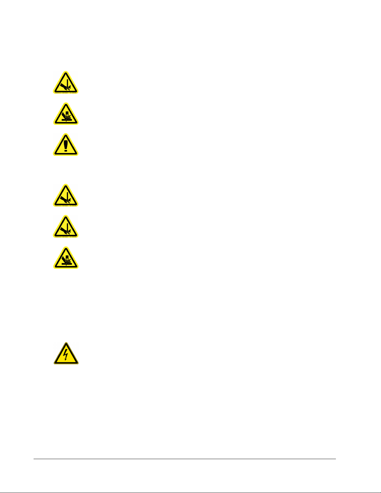
Mechanical Components
WARNING: The Luminex® FLEXMAP 3D® instrument has parts that move
during operation.
Risk of personal injury is present. The moving parts present puncture,
pinching, and hand-crushing hazards. Keep your hands and fingers away
from the XY slot, syringe pumps, and sample probe during operation.
Observe all warnings and cautions. Keep the access doors closed during
normal operations.
Swivel Base
WARNING: The optional swivel base available with the Luminex® FLEXMAP
3D® system includes moving parts and possible pinch points.
Those factors present the possibility of injury.
WARNING: Use care when handling the swivel base to avoid pinch point
injuries.
WARNING: Make certain the swivel base rests securely on a stable surface,
to avoid any possibility of toppling.
Indicator Lights
The lights inside the front door of the
status of the system and are harmless. The blue light-emitting diodes (LEDs) do not emit light
in the UV spectrum.
Electrical Components
WARNING: Do not perform any maintenance or cleaning of the electrical
components in the system, with the exception of replacing
fuses.
The following fuse caution label appears on the back of the Luminex®
Luminex® FLEXMAP 3D® instrument indicate the on/off
FLEXMAP 3D®.
Luminex® FLEXMAP 3D® Hardware User Manual
6
For research use only. Not for use
in diagnostic procedures.
Page 17
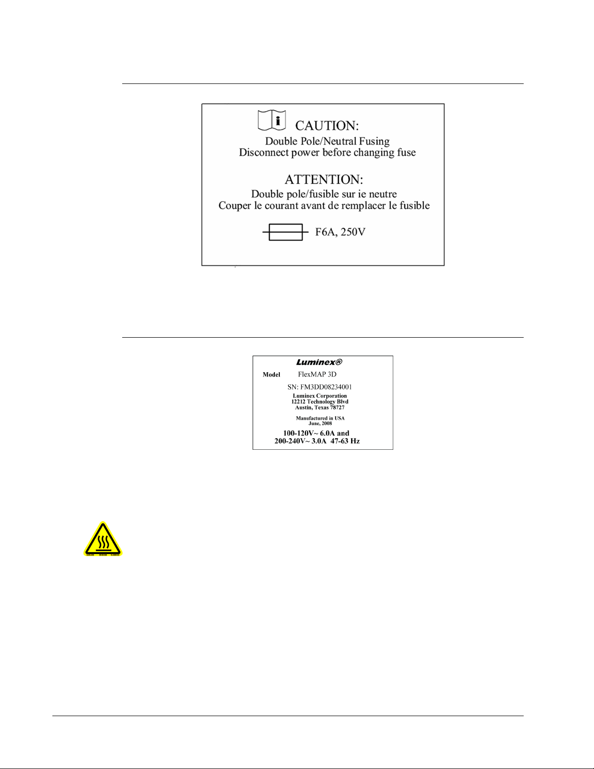
FIGURE 5.
Fuse Caution Label
Heat
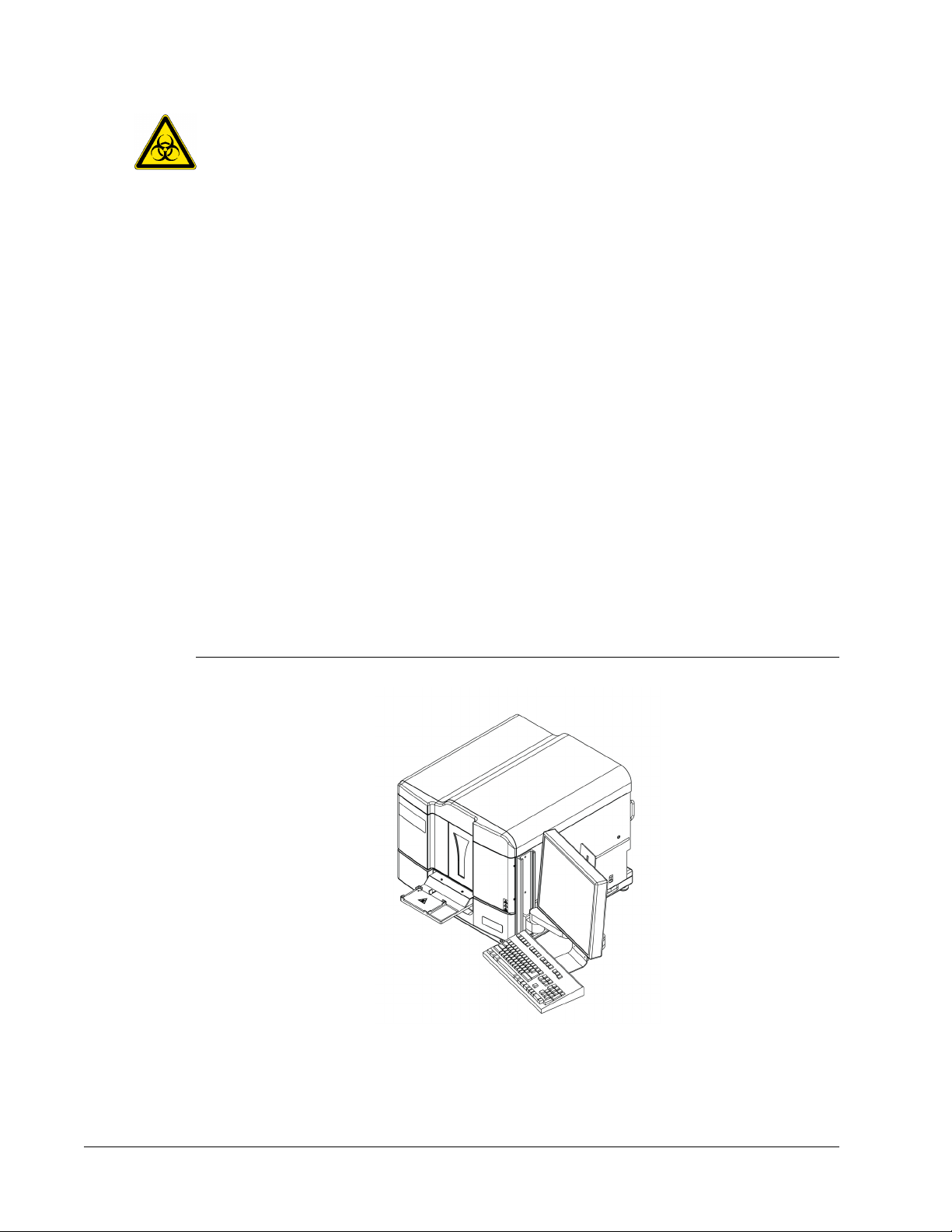
The following voltage label appears on the back of the FLEXMAP 3D®
the FLEXMAP 3D® serial number, model number, power requirements, and manufacturer’s
information.
FIGURE 6.
The heater plate, used to warm the heater block of the XY platform, can be heated between
35°C and 60°C.
Serial Number and Voltage Label
WARNING: The heater plate of the Luminex® FLEXMAP 3D®
may be hot and can cause personal injury if touched. Do not
touch the heater plate.
instrument. It displays
XY platform
Decontamination Procedure
Occasions may arise when it becomes necessary to decontaminate the entire
FLEXMAP 3D® instrument, for example, prior to shipping. If you must decontaminate the
instrument, sanitize the accessible surfaces and the internal fluidics system. This is
particularly important when biohazardous samples have been run.
For research use only. Not for use in diagnostic procedures.
Luminex
®
Safety
7
Page 18
WARNING: Wear appropriate personal protective equipment when handling
parts that come into contact with potentially biohazardous
samples.
To decontaminate the FLEXMAP 3D® instrument:
1. Remove all specimens and all FLEXMAP 3D® reagents.
2. Use the software to run a sanitize command with the diluted (10% to 20%) household
bleach solution. Leave deionized water and household bleach solution diluted to 10% to
20% in water in the system.
3. Use the software to run two wash commands with deionized water.
4. Turn off the power switch and unplug the cord from the outlet.
5. Wash all exterior surfaces with a mild detergent followed by the diluted (10% to 20%)
household bleach solution.
6. Open the front doors of the system. Clean all accessible surfaces with mild detergent
followed by the diluted (10% to 20%) household bleach solution.
Installation of Instrument
Luminex handles the packing, shipping, unpacking, and installation of the Luminex
FLEXMAP 3D® system. Luminex recommends that users and laboratory personnel do not
uninstall, move, or install the system.
For site preparation and facilities requirements, see the section titled Installation.
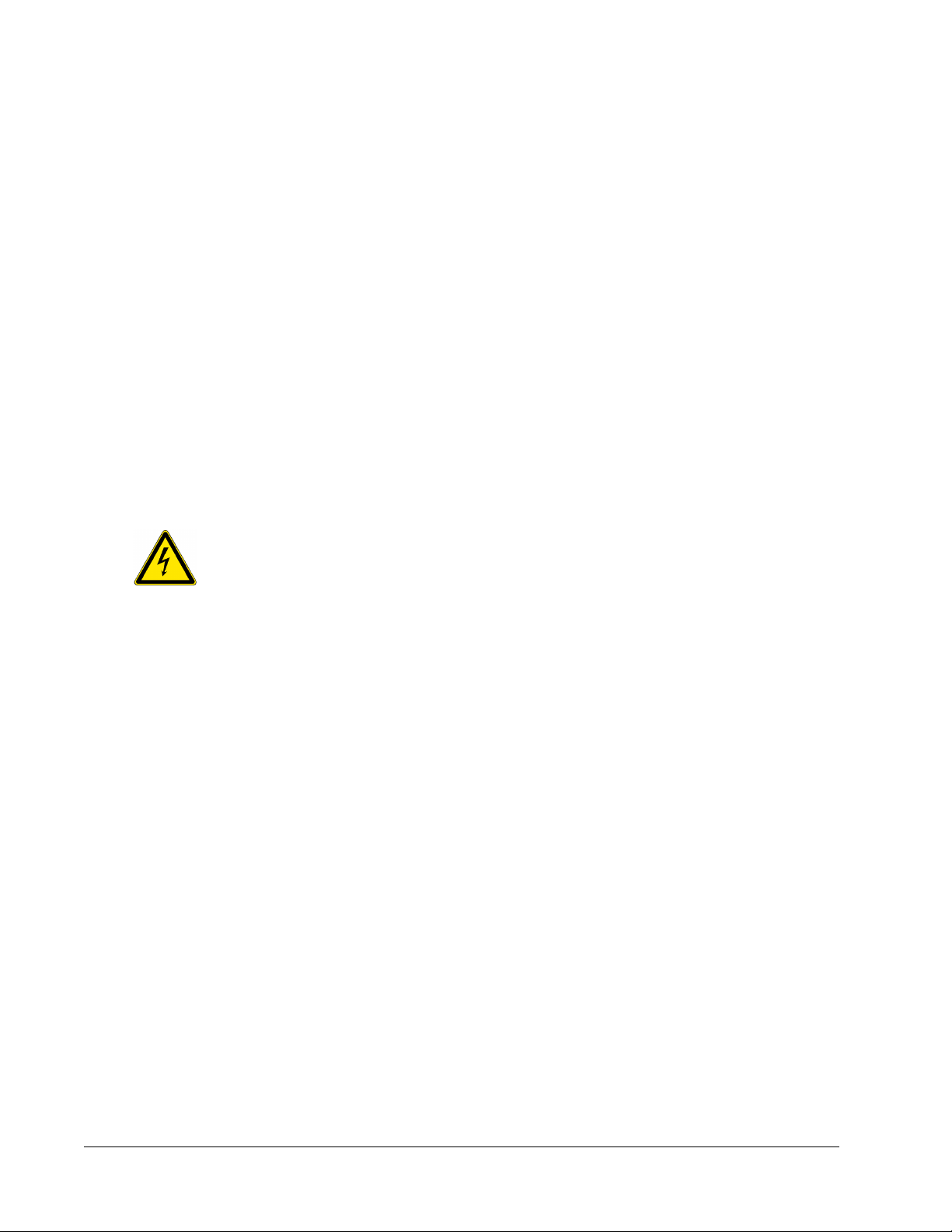
FIGURE 7.
Installed FLEXMAP 3D® System
®
Luminex® FLEXMAP 3D® Hardware User Manual
8
For research use only. Not for use
in diagnostic procedures.
Page 19

Disposal of Instrument
NOTE: Within the European Union and other jurisdictions, in accordance
with Directive 2002/96/EC of the European Parliament and of the
Council regarding Waste Electrical and Electronic Equipment
(WEEE), you must properly dispose of electrical and electronic
equipment when it reaches its end of life.
If you are disposing of a Luminex® FLEXMAP 3D® instrument, decontaminate the system.
See the section titled “Decontamination Procedure”. Next, contact Luminex Technical
Support for a Return Material Authorization (RMA) number at +1-512-381-4397 (outside of
the U.S.). Return the equipment to the following Luminex location:
Luminex Corporation
12201 Technology Blvd., Suite 130
Austin, Texas 78727
USA
For information about disposal of
jurisdictions, contact Luminex Technical Support at 1-877-785-2323 within the US and at
+1-512-381-4397 outside of the US.
For information about disposal of the barcode scanner, PC, or monitor, refer to the
manufacturer documentation.
FLEXMAP 3D® outside of the European Union and other
For research use only. Not for use in diagnostic procedures.
Safety
9
Page 20

Luminex® FLEXMAP 3D® Hardware User Manual
10
For research use only. Not for use
in diagnostic procedures.
Page 21

Chapter 2: Technical Overview
This chapter reviews the technical aspects of the Luminex®
operation, system components, subsystems, recommended additional equipment, and
specifications.
How the FLEXMAP 3D System Operates
The Luminex® FLEXMAP 3D® system, in combination with xMAP® (Multi-Analyte Profiling)
technology, will simultaneously measure up to 500 analytes from a single sample. xMAP
technology incorporates microspheres, proprietary dyeing processes, flow cytometry based
fluidics, lasers, the latest in high-speed digital signal and advanced computer algorithms,
enabling a multi-analyte detection system that demonstrates excellent sensitivity and
specificity.
An established proprietary process created by Luminex to internally dye same-size
polystyrene microspheres with multiple fluorophores facilitates the creation of five hundred
distinguishable microspheres when these fluorophores are combined in varying
concentrations. The microspheres, discriminated by color, are excited by two lasers in the
FLEXMAP 3D® instrument. The resulting emission is detected by avalanche photo diodes
(APDs) in three classification channels (CL1, CL2, and CL3) that is then further analyzed
using a separate APD in a doublet discriminator (DD) channel, which measures bead size
through side-scatter.
Analytes are bound to xMAP microspheres using the same surface chemistry used with
earlier Luminex instruments (LX100/200). Reporters, tagged with fluorescent labels excited at
a different wavelength than the internal dyes, bind to the analyte of interest and are detected
by a photomultiplier tube (PMT) in a reporter channel (RP1), allowing for quantitative
analysis. As the microspheres in a fluid stream pass rapidly through the laser beams, highspeed digital signal and computer algorithms discriminate which analyte is being carried on
each microsphere and quantifies the reaction based on fluorescent reporter signal. The
results are analyzed by the system software and presented in a readable format for analysis.
FLEXMAP 3D® system:
11
Page 22
Subsystems
The Luminex®
mechanical, and optical. The following topics describe the user-accessible components of
each subsystem.
Electronics
The electronics system provides the power for operation and control of the FLEXMAP 3D
system and communication between its parts.
Power Input Module
The power input module contains the input power plug and fuses. This is the protective
earthing point for the Luminex® FLEXMAP 3D® system. The mating power cord connector
type is IEC-320-C13. The mating power cord provides electrical power to the instrument
when it is connected to an electrical outlet and is the means of disconnection. The power
input auto-senses the voltage range. See the "Back of the FLEXMAP 3D® Instrument" image
below.
WARNING: Do not obstruct this means of disconnection. Connect only to
Communications Ports (USB Type B Connector)
FLEXMAP 3D® instrument includes four subsystems: electronic, fluidic,
®
outlets that contain protective earthing. Before changing a fuse,
turn off the instrument and unplug the power cord to avoid any
danger of electrical shock.
The communications port connects the
See the "Back of the FLEXMAP 3D® Instrument" image below.
Luminex® FLEXMAP 3D® instrument to the computer.
Luminex® FLEXMAP 3D®
12
Hardware User Manual
For research use only. Not for use
in diagnostic procedures.
Page 23
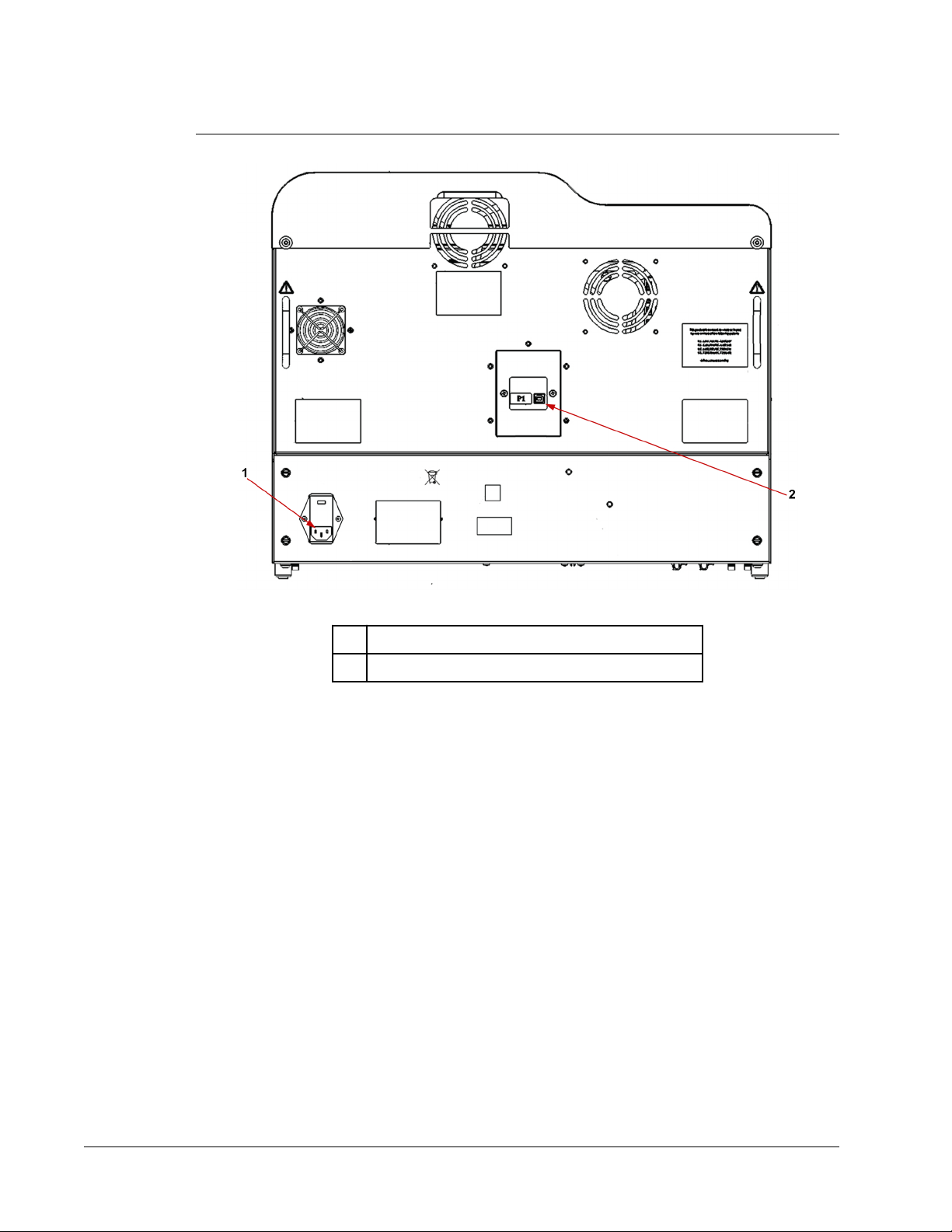
FIGURE 8.
Back of the FLEXMAP 3D® Instrument
Fluidics
The fluidics system handles the flow of liquid through the
instrument.
Access Doors
The Luminex® FLEXMAP 3D® system has two front access doors. The left door supplies
access to a door ventilation filter and the sheath filter. The right door supplies access to a
door ventilation filter, the sample probe, and the syringe pumps. See the "Front of the
FLEXMAP 3D® Instrument" image below.
1 Power Input Module
2 Communications Port P1 (USB type B)
Luminex® FLEXMAP 3D
®
For research use only. Not for use in diagnostic procedures.
Technical Overview
13
Page 24
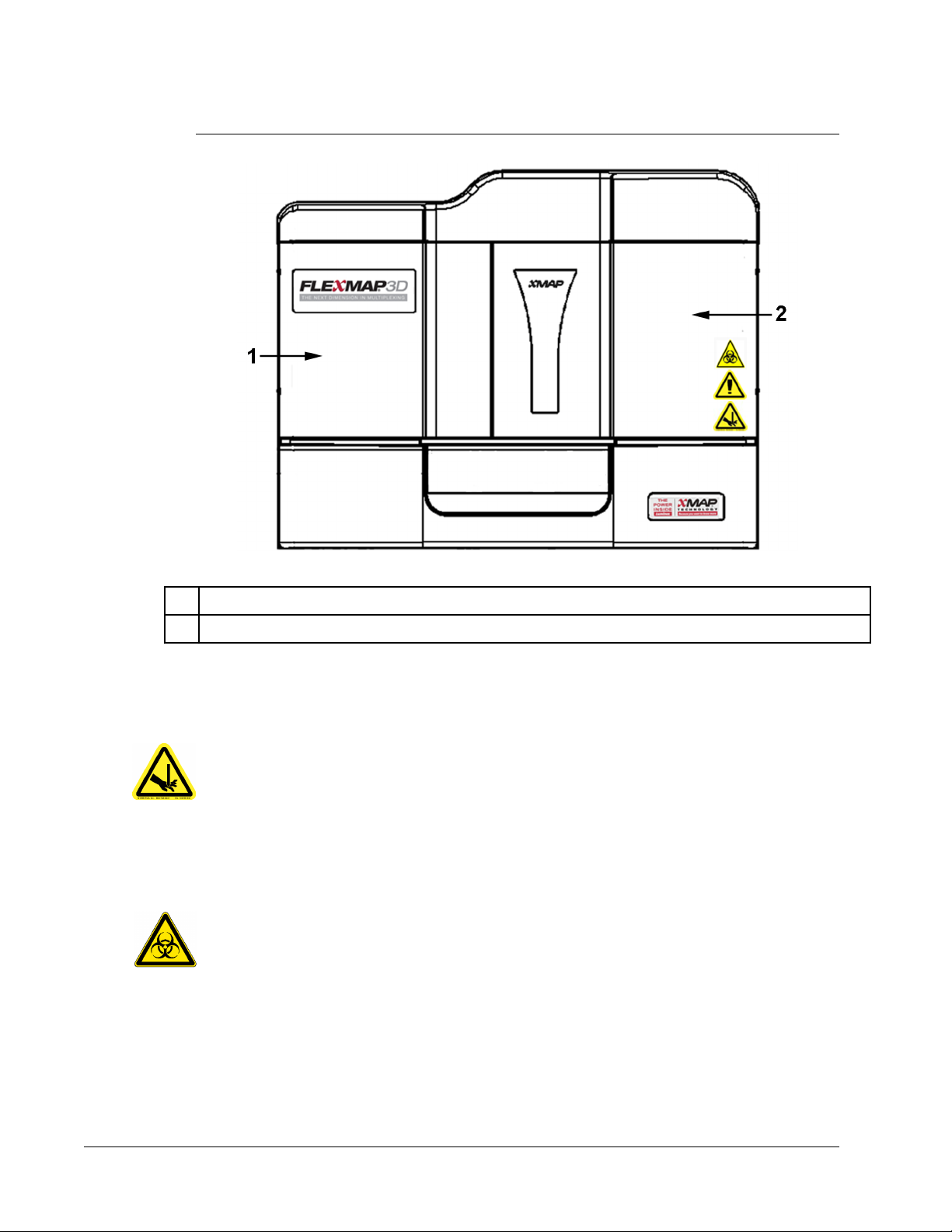
FIGURE 9.
Front of the FLEXMAP 3D® Instrument
1 Left door, with access to sheath filter and door ventilation filter
2 Right door, with access to syringe pumps, door ventilation filter, and sample probe
Sample Probe
A stainless steel sample probe acquires the sample. See the "Sample Probe" image below.
WARNING: Avoid contact with moving parts.
Cheminert® Fitting
This fitting attaches the sample probe to the sample tubing. Disconnect this fitting when you
remove the sample probe. See the "Sample Probe" figure below.
WARNING: Wear appropriate personal protective equipment when handling
parts that come into contact with potentially biohazardous
samples.
Luminex® FLEXMAP 3D® Hardware User Manual
14
For research use only. Not for use
in diagnostic procedures.
Page 25
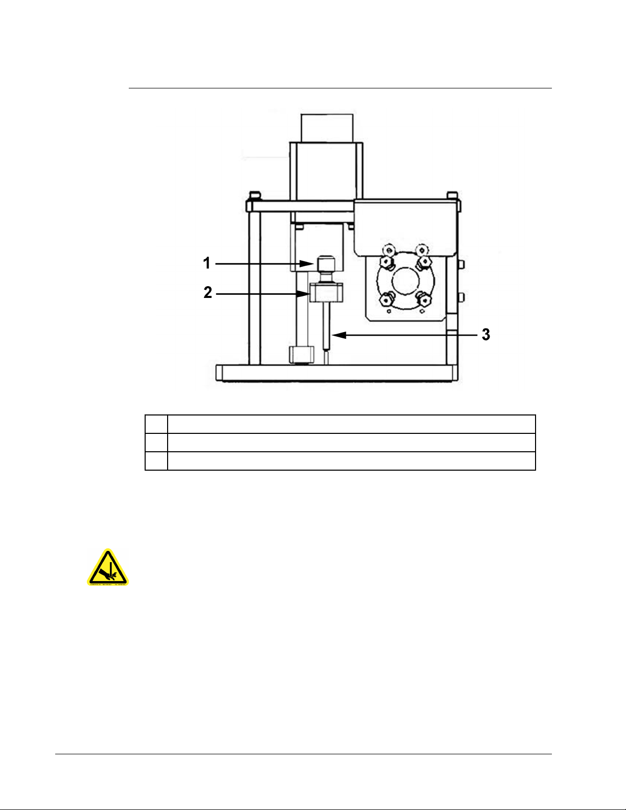
FIGURE 10.
Sample Probe
1 Cheminert fitting
2 Attachment point on Cheminert fitting for sample tubing
3 Sample probe, in up position
Syringe Pump
The syringe delivers a sample from the microtiter plate to the cuvette. See the "Syringe
Pump" image below.
WARNING: Avoid contact with moving parts.
For research use only. Not for use in diagnostic procedures.
Technical Overview
15
Page 26
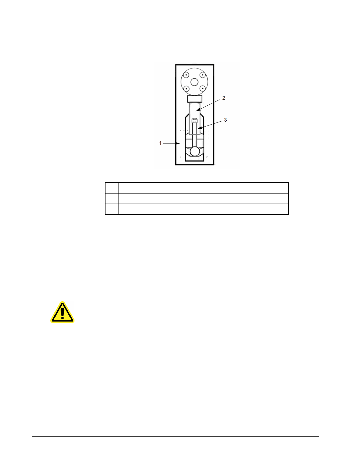
FIGURE 11.
Syringe Pump
1 Syringe arm (within dotted lines)
2 Glass syringe barrel
3 Syringe plunger
Sheath Filter
The sheath filter removes particles greater than ten microns in diameter from the sheath fluid.
See the "Fluidics Bay" image below.
Fluidics Bay
The waste and sheath connectors, located on the front of the fluidics bay, connect to the
sheath fluid and waste fluid containers using clear tubing. The sheath fluid connector is blue
and the waste connector is orange. See the "Fluidics Bay" image below.
CAUTION: Wear appropriate personal protective equipment when handling
parts that come into contact with potentially biohazardous
samples.
Luminex® FLEXMAP 3D® Hardware User Manual
16
For research use only. Not for use
in diagnostic procedures.
Page 27

FIGURE 12.
Fluidics Bay
Waste Fluid Container
The waste fluid container receives waste from the system. To maintain a stable flow rate, do
not move the waste line or container during system operation and make certain the waste
fluid container is properly vented. Place the container at least three feet below the surface on
which the instrument rests. You can place it as far away from the instrument as the tubing
allows. Never place it on top of the instrument. Refer to safety instructions for the waste fluid
container within the Fluidics section of the manual.
WARNING: Wear appropriate personal protective equipment when handling
Mechanics
The mechanical subsystem of the
system.
Replaceable ventilation filters clean the air used to cool the instrument and pressurize sheath
fluid. The four filters must be checked and cleaned as prescribed in the Maintenance chapter
1 Sheath filter
2 Blue tubing attached to sheath fluid container
3 Orange tubing attached to waste fluid container
parts that come into contact with potentially biohazardous
samples.
Luminex® FLEXMAP 3D® instrument includes a filter
For research use only. Not for use in diagnostic procedures.
Technical Overview
17
Page 28
of this manual. The "Fluidics Bay" image above and "Front Door Ventilation Filters" image
below show the location of these filters.
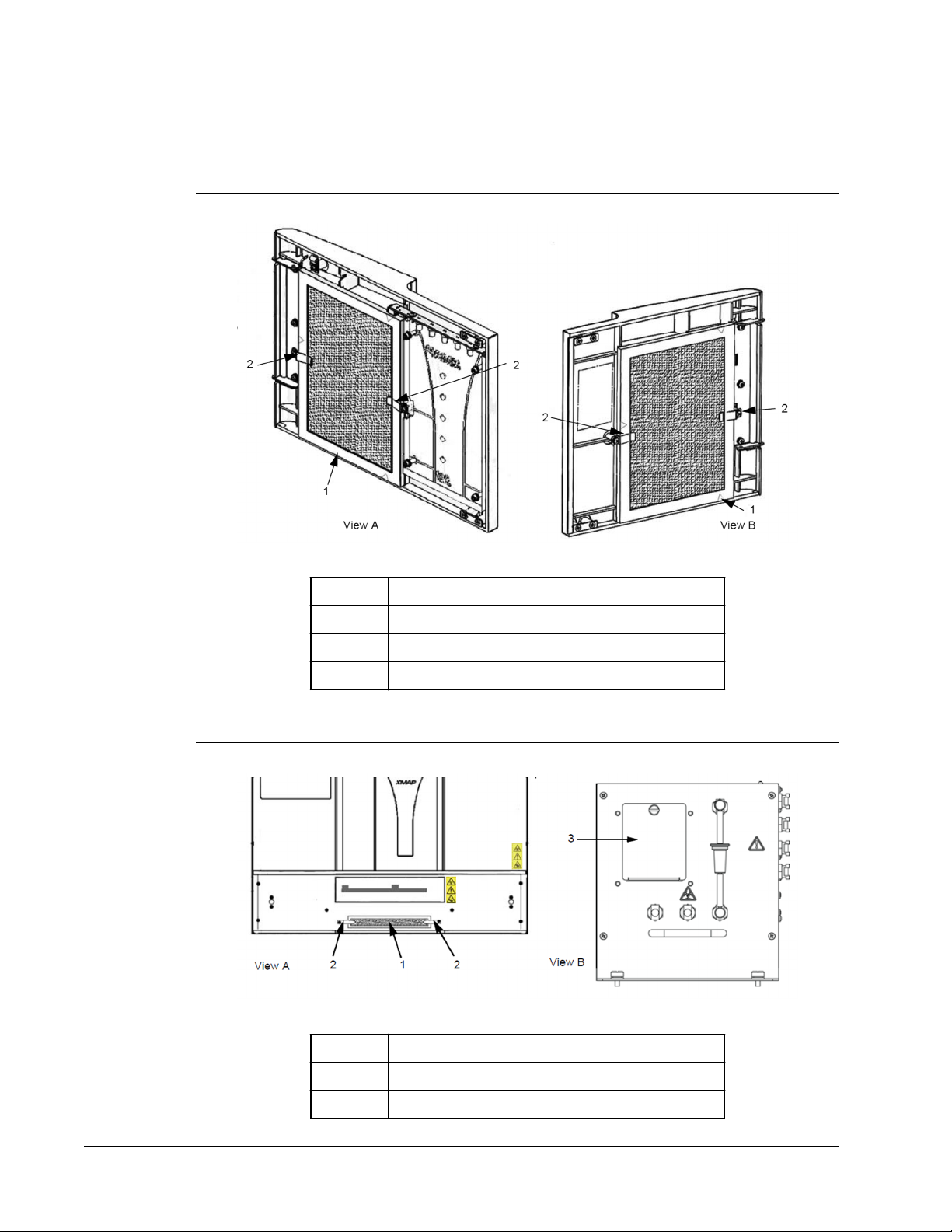
FIGURE 13.
Front Door Ventilation Filters
View A Right front door, viewed from inside
View B Left front door, viewed from inside
FIGURE 14.
1 Filter
2 Holding clamp
XY and HEPA Filters
View A Front of XY, with XY cover removed
View B Front of fluidics bay, behind left front door
1 XY filter
Luminex® FLEXMAP 3D® Hardware User Manual
18
For research use only. Not for use
in diagnostic procedures.
Page 29

TABLE .
Continued
2 Holding clamp
3 Cover over HEPA air filter
Optics
The optical system consists of the optical assembly and the excitation lasers. The optical
components do not require manual adjustment by the user.
System Components
The following topics describe details of the three components of the
system: software, reagents, and hardware.
Luminex® xPONENT® Software
Luminex® xPONENT® software provides complete control of the Luminex® FLEXMAP 3D
instrument and performs the analysis. The software requires a dedicated PC. For updated
information about the PC or operating system, access http://www.luminexcorp.com. Click the
Support link to open the FAQ list.
Under most circumstances, the PC that comes with the FLEXMAP 3D® system is preloaded
with xPONENT software. Luminex provides a software CD to use if you need to reinstall the
software or need to install it on another computer. If you install the software on another PC,
be sure that the PC meets the minimum specifications, including 4.0 GB of RAM and a 2.66
GHz processor. The number of installations you can perform is limited by your license.
The software CD automatically installs the basic software only. To install the various
upgrades, contact Luminex Technical Support. A Technical Support representative can
supply you with the correct license number to install upgrades.
CAUTION: If you need to uninstall the software, follow carefully the
procedure provided by Luminex Technical Support.
The software is documented in two ways: online help, which can be accessed from within the
application itself, and in PDF form, which is available on the Luminex website and on CDs
included with the system.
Luminex® FLEXMAP 3D
®
®
Reagents
Luminex® xMAP® technology requires two kinds of reagents:
•
Common laboratory reagents
• Reagents created especially for Luminex instruments
For research use only. Not for use in diagnostic procedures.
CAUTION: Luminex recommends that you do not install additional software
on the PC that runs xPONENT. The operation of xPONENT has
been validated only when it is the only program running on the
dedicated PC.
Technical Overview
19
Page 30

CAUTION: Adhere to standard laboratory safety practices when handling
hazardous, toxic, or flammable reagents and chemicals. Contact
Luminex Technical Support when in doubt about compatibility of
cleaning and decontamination agents or materials.
Required Laboratory Reagents
•
10 - 20% household bleach
• 70% isopropanol or 70% ethanol
• 0.1N NaOH
• Sporicidin® Disinfectant
• Mild detergent
• Deionized water
WARNING: Isopropanol and ethanol are flammable liquids. Keep them away
from heat, open flames, and sparks in a well-ventilated area.
Remove them from the instrument when they are not in use.
Luminex® xMAP® Technology Reagents
•
F3DCAL1 - Classification Calibrator (calibrates DD, CL1, CL2, CL3 - for all xMAP
microsphere applications other than MagPlex microspheres)
• F3DeCAL1 - Classification Calibrator (calibrates DD, CL1, CL2, CL3 - for MagPlex
microsphere-based applications only)
• F3DCAL2 - Reporter Calibrator (calibrates RP1 standard and enhanced range - for all
xMAP microspheres)
• F3DCAL3 - EDR Calibrator (calibrates RP1 extended range - for all xMAP microspheres)
• F3DVER1 - Classification Verifier (verifies DD, CL1, CL2, CL3 - for all xMAP microsphere-
based applications other than MagPlex microspheres)
• F3DeVER1 - Classification Verifier (verifies DD, CL1, CL2, CL3 - for MagPlex microsphere-
based applications only)
• F3DVER2 - Reporter Verifier (verifies RP1 standard and enhanced PMT and extended
range - for all xMAP microspheres)
• Fluidics1 - xMAP Fluidics 1 (verifies fluidic integrity and well-to-well microsphere carryover)
• Fluidics2 - xMAP Fluidics 2 (verifies fluidic integrity and well-to-well microsphere carryover)
• Luminex xMAP Sheath Fluid
®
CAUTION: Protect xMAP reagents from light at all times to avoid
photobleaching of the microspheres.
CAUTION: Luminex reagents contain ProClin® as a preservative. This can
cause allergic reactions in some people.
Luminex® FLEXMAP 3D® Hardware User Manual
20
For research use only. Not for use
in diagnostic procedures.
Page 31

CAUTION: Luminex calibrators and verifiers contain sodium azide. Sodium
azide is toxic and may also react with lead and copper plumbing
to form highly explosive metal azides. On disposal, flush drains
with a generous amount of cold water to prevent azide build-up.
Consult the manual guideline Safety Management No. CDC-22,
Decontamination of Laboratory Sink Drains to remove Azide
Salts (Centers for Disease Control, Atlanta, Georgia, April 30,
1976).
Luminex® FLEXMAP 3D® Hardware
The Luminex® FLEXMAP 3D®
• The FLEXMAP 3D® instrument
• Personal computer (PC) and accessories
• Stereo speakers
• Power cables
• Three sample probes
• Off-plate reagent area
• 96 and 384 heater blocks
• Empty cubitainer for waste
• Sheath fluid intake line
• Waste fluid outtake line
• USB communication cable
• Barcode reader (optional)
• Sample probe height alignment kit and 384-well plate Probe Height Adjustment tool
• Monitor arm
NOTE: For information on calibrating the probe correctly, refer to the
FLEXMAP 3D 384-Well Plate Probe Height Adjustment Tool section.
system includes the following hardware:
Recommended Additional Equipment
Successful operation of the
equipment.
Uninterruptible Power Supply (UPS) or Surge Protector
Luminex recommends using either an uninterruptible power supply (UPS) or a surge
protector to protect your system from power outages. Use a UPS that provides 1300 watts for
at least 45 minutes. Select a surge protector that fits your requirements with regard to
electrical environment, endurance, suppressed voltage rating, and method of protection. The
surge protector requires three outlets and a minimum rating of 1500 watts. Either piece of
equipment should be listed by Underwriters Laboratory (UL) or a similar listing body, certified
by Canadian Standards Association (CSA), and marked Conformité Europeénne (CE) for
nondomestic use.
For research use only. Not for use in diagnostic procedures.
Luminex® FLEXMAP 3D® system may require additional
Technical Overview
21
Page 32

Printer
Use a printer compatible with
Microsoft® Windows XP SP3.
Barcode Labels
Use Code 128 barcode label type when scanning barcode labels into the system.
Vortex
Use VWR product number 58816-12, with a speed range of 0 to 3200 rpm, or equivalent.
Bath Sonicator
Use Cole-Parmer® product number 08849-00, with an operating frequency of 55 kHz, or
equivalent.
Specifications and Limitations
The Luminex® FLEXMAP 3D® system is designed to fit a series of standards for speed,
accuracy, sensitivity, and capacity. The following topics provide the specifications and
limitations for the Luminex FLEXMAP 3D® system.
CAUTION: Read and observe specifications and limitations carefully.
General
Indoor laboratory and professional use only
Physical dimensions: 58.4 cm (23 inches) W x 65.3 cm (25.7 inches deep, including the required 1.25 inches for
proper cooling) D x 54.7 cm (18.0 inches) H. Additional space required for the arm, monitor,
keyboard, mouse and optional barcode scanner does not exceed 64.8 cm (25.5 inches) W
by 61 cm (24.0 inches) D.
Weight: up to 91 kg (200 lbs), including the instrument, monitor arm, monitor and accessories such
as the keyboard, mouse, and barcode scanner.
Installation Category: II
Pollution degree: 2
Operating temperature: 15°C to 30°C (59°F to 86°F)
Operating humidity: 20% to 80%, noncondensing
Shipping and storage
temperature:
Shipping and storage
humidity:
0 to 50°C (32° F to 122° F)
20% to 80%, noncondensing
Luminex® FLEXMAP 3D® Hardware User Manual
22
For research use only. Not for use
in diagnostic procedures.
Page 33

TABLE .
Temperature control: Maintains samples using the heater block at a constant temperature from 35°C to 60°C
Altitude: Operation up to 2400 m (7874 ft.) above mean sea level
Automatic transfer of assay protocols and new reagent information into the system using a large capacity read/write DVD
Automatic sampling from a 96- or 384-well microtiter plate, beginning from any well position
Automatic real-time analysis
Analyzes multiple assay protocols per microtiter plate
Barcode reader entry of sample IDs
System initialization: < 45 minutes (including laser warmup, required software procedures, and weekly
System verification: 5 minutes
FLEXMAP 3D® warmup: 30 minutes. A system that remains inactive for at least four hours requires a warm-up to
Produces sound pressure levels below 85 dBA
Operating Shock: The instrument will be able to operate while experiencing limited shock.
Continued
(95°F to 131°F), +/- 1°C of setpoint.
calibration)
restart the lasers. The system resets the four-hour internal clock after acquiring the sample,
running system calibrators, running system controls, or warming up the instrument.
Pulse amplitude: 1 m/s2 maximum
•
• Pulse direction: along any axis defined by a rear corner of the instrument, in either
direction
• Reference IEC 60068-2-27 Basic Environmental Testing Procedures Part 2: Tests -Test
Ea and Guidance: Shock
Note: This specification is not meant to comprehensively describe all forms of shock the
instrument may be exposed to in use; it is only intended to serve as a measure of the
system's robustness.
Although the system shall be able to withstand a shock pulse as described above without
compromising reliable operation, extended exposure to shock whether or not it exceeds the
pulse defined above is not recommended and may result in instrument failure.
Operating Vibration: The instrument will be able to operate while experiencing limited vibration.
• Direction shall be along any axis defined by a rear corner of the instrument.
• Sinusoidal, limited to frequency ranges in table below
Frequency Range Limit Type of Limit
0 to 10 Hz 0.35 mm ± 10% (0.7 mm peak-to-peak) Displacement
10 Hz to 100 Hz 1 m/s2 ± 10% peak Acceleration
Reference IEC 60068-2-6 Environmental Testing Procedures Part 2: Tests - Test Fc:
Vibration (Sinusoidal).
Note: Although the instrument shall be able to operate while experiencing vibration as
described above, extended exposure to vibration whether or not it exceeds these limits is
not recommended and may result in instrument failure.
For research use only. Not for use in diagnostic procedures.
Technical Overview
23
Page 34

Electronics
USB 2.0-compatible communications link for fast data transfer
Input voltage range: 100-120 V~, 6.0 A, 50/60 Hz or, 200-240 V~, 3.0 A, 50-60 Hz
Optics
Reporter channel detection: A/D resolution 16 bits
Reporter channel dynamic
range:
Reporter laser: 532 nm, nominal output 15.0+5%/-0% mW, diode-pumped; mode of
Classification laser: 638 nm, nominal output 12.0 to 12.5 mW, diode; mode of operation,
Reporter detector: Photomultiplier tube, detection bandwidth of 565 to 585 nm
Classification detector: Avalanche photo diodes with temperature compensation
Doublet discrimination
detector:
Fluidics
Cuvette: 200 micron square flow channel
Sample injection rate: 2μL/second
Sample uptake volume: 20 to 200μL
Sheath flow rate: 7.9 (+/- 0.9) mL/min
Sheath pressure: 8 to 13 psi for normal operations; 15 psi maximum
≥ 4.5 decades of detection (verified with beads dyed with high levels
of organic dyes)
operation, continuous wave (CW); maximum output power 50 mW
continuous wave (CW); maximum output power 15 mW
Avalanche photo diodes with temperature compensation
Microspheres
Distinguishes 1 to 500 unique xMAP microspheres in a single sample
Classification of xMAP
microspheres:
Total system
misclassification of xMap
microspheres:
Internal sample carryover: < 1.5%
Detects a minimum of 500 fluorochromes of phycoerythrin (PE) per xMAP microsphere
Luminex® FLEXMAP 3D® Hardware User Manual
24
≥ 80%
≤ 4%
For research use only. Not for use
in diagnostic procedures.
Page 35

TABLE .
Detects and distinguishes surface reporter fluorescence emissions at 575 nm on the surface of 1 to
500 unique xMAP microspheres in a single sample
Soluble background fluorescence emission at 575 nm automatically subtracted from fluorescence
intensity values.
Continued
Microtiter Plates
The Luminex® FLEXMAP 3D® system processes a 96-well microtiter plate in less than 20
minutes and a 384-well microtiter plate within 1 hour and 15 minutes, with 2500 microspheres
per region per well, counting 100 microspheres in each region.
Microtiter plates with 96 and 384 wells must be compatible with the microtiter heater block
temperature (from 35 to 60°C or 95° to 131°F) when the heater block is in use.
All microtiter plates (96 or 384 wells) have standard width (85.6 mm) and length (127.9 mm).
Depth varies depending on the type of well. To be compatible with the
instrument, the maximum allowable depth is 1”. Plates must have minimum 0.06” lip height,
standard distance from well center to well center (9 mm on 96-well plate), and standard
distance from A1 center to plate center in both length and width. To be compatible in size
with the microtiter heater block, the plate must fit into the heater block so that the top is flush
with the heater block.
FLEXMAP 3D
®
For research use only. Not for use in diagnostic procedures.
Technical Overview
25
Page 36

Luminex® FLEXMAP 3D® Hardware User Manual
26
For research use only. Not for use
in diagnostic procedures.
Page 37

Chapter 3: Maintenance and Cleaning
To ensure accurate test results, properly clean and maintain the Luminex® FLEXMAP 3D
system. Read and follow all instructions in this section. Perform adequate maintenance and
cleaning to avoid inaccurate results and potential hazards. To facilitate your maintenance
process, print out and use the maintenance logs found
General Maintenance Precautions
Observe the following general maintenance precautions, which were explained in more detail
in the previous chapters:
Personnel who use, maintain, or clean the Luminex®
should be trained in standard laboratory safety practices and should follow
those practices when handling the instrument.
Samples and waste fluid can contain biohazardous material. Where exposure
to biohazardous material, including in an aerosol form, exists, follow
appropriate biosafety procedures, use personal protective equipment, and use
ventilation devices.
Do not remove the cover of the FLEXMAP 3D® instrument under any
circumstances.
®
in the Maintenance Log section.
FLEXMAP 3D® instrument
Avoid contact with moving parts. Disconnect the instrument from the power
source when the procedure instructs you to do so.
Daily Maintenance
NOTE: Most of the daily maintenance tasks for the Luminex®
system, including system initialization, warmup, and shutdown, can
be performed using available software commands. For details about
FLEXMAP 3D
®
27
Page 38

the performance of these activities, see the appropriate Luminex
software manual or Luminex online help.
Initializing the Luminex® FLEXMAP 3D® Instrument
NOTE: Use the software to perform system initialization.
The software provides three options for system initialization:
• Warmup, fluidics
• Warmup, fluidics, verification
• Warmup, fluidics, verification, and calibration
Select the option you want. Warmup, fluidics, and verification should be part of the daily
maintenance of the instrument; calibration can be limited to weekly maintenance unless
otherwise specified by assay instructions.
NOTE: If the instrument temperature falls out of the delta cal range,
recalibrate it. For information about the delta cal range, see the
appropriate Luminex software manual or Luminex online help.
Warming Up the Luminex® FLEXMAP 3D® Instrument
NOTE: If the Luminex® FLEXMAP 3D® instrument is powered on but idle for
more than four hours, both lasers turn off. Consequently, the
instrument should be warmed up again. Use the software to perform
a warmup.
Maintaining Fluids
Periodically monitor fluid levels. Replace the empty sheath fluid container as needed. If the
Luminex® FLEXMAP 3D® instrument operates with an empty sheath fluid container, the lack
of sheath fluid may interrupt a sample and prevent further samples from being collected.
CAUTION: Use only xMAP Sheath Fluid or another Luminex-approved
sheath fluid. Use of any other sheath fluid constitutes improper
use and can void the warranty provided by Luminex and/or its
authorized partner.
Optimally, the waste line should be routed to a laboratory drain. If you use a waste container,
monitor waste fluid levels periodically. The volume of the waste container should be at least
as large as the volume of the sheath container. Do not allow the waste fluid container to
overflow. Empty the waste fluid container each time you replace or fill the sheath fluid
container.
Place the waste fluid container at least three feet below the surface on which the
3D® instrument rests.
FLEXMAP
WARNING: Do not place the waste fluid container on top of the instrument.
Luminex® FLEXMAP 3D® Hardware User Manual
28
For research use only. Not for use
in diagnostic procedures.
Page 39

WARNING: Do not move the waste line vertically while the FLEXMAP 3D
instrument is running.
Contact Luminex Technical Support before relocating the waste fluid container or rerouting
the waste line. You can move the line temporarily for cleaning and maintenance.
To empty the waste fluid container:
1. Disconnect the waste fluid container from the FLEXMAP 3D® instrument.
2. Discard the waste from the waste fluid container in accord with all local, state, federal,
and country specific biohazard handling regulations.
WARNING: Waste fluid can contain biohazardous infectious agents. Where
exposure to potentially biohazardous materials (including
aerosol) exists, follow appropriate biosafety procedures and use
personal protective equipment such as gloves, gowns,
laboratory coats, face shields (or mask and eye protection),
respirators, and ventilation devices.
®
Shutting Down the Luminex® FLEXMAP 3D® Instrument
NOTE: Use the software to perform system shutdown. The shutdown
procedure is intended to shut down the Luminex® FLEXMAP 3D
instrument for short periods, for example, overnight, for a weekend,
or up to a week.
To shut down the FLEXMAP 3D instrument for a long period, see the section titled Storing
the FLEXMAP 3D Instrument.
Weekly Maintenance
NOTE: Some of the weekly maintenance tasks for the Luminex® FLEXMAP
3D® system can be performed using available software commands.
For details about the performance of these activities, see the
Luminex® xPONENT® Software User Manual or Luminex online help.
Weekly maintenance includes using the software to perform a
weekly maintenance routine, removing clogs, cleaning the sample
probe, calibrating the system, and visually inspecting the instrument.
Running Weekly Maintenance
NOTE: Use the software to perform a weekly maintenance routine.
®
For research use only. Not for use in diagnostic procedures.
Maintenance and Cleaning
29
Page 40

Removing Clogs
NOTE: If you frequently use the Luminex®
concentrated serum or other debris ridden samples, Luminex
recommends that you use the software to perform a clog removal
routine weekly. Luminex recommends using sodium hydroxide
(NaOH) to remove clogs.
To remove clogs:
1. Add 0.1N sodium hydroxide solution to reservoir RB1 on the off-plate reagent block.
2. Use the software to perform a clog removal routine.
WARNING: Sodium hydroxide is extremely caustic. If it comes into contact
with skin, it can burn and cause tissue damage without causing
pain. Always wear gloves and goggles when working with
sodium hydroxide.
Cleaning the Sample Probe
WARNING: Avoid contact with moving parts. If a plate is running, use the
software to execute Stop to prohibit exposure to moving parts.
Refer to the software manual for instructions. The
FLEXMAP 3D® system must not be performing any operations
while you carry out this maintenance procedure.
To clean the sample probe:
FLEXMAP 3D® system to test
Luminex
®
1. Use the software to execute STOP if a plate is running. Refer to the software manual for
instructions. The FLEXMAP 3D® system must not be performing any operations while
you carry out this maintenance procedure.
2. Remove the sample probe.
a. Open the right front door of the FLEXMAP 3D® instrument.
b. Unscrew the Cheminert fitting on top of the probe completely.
c. Grasp the probe gently and push up.
d. Lift the probe out of the top of the probe holder.
3. Clean the sample probe using either a bath sonicator or a 10 mL syringe. If you are using
a bath sonicator, place the tip of the sample probe in the bath sonicator for 2 to 5
minutes. If you are using a syringe, force deionized water through the tip of the sample
probe to its large end. This dislodges any debris clogging the tip.
Luminex® FLEXMAP 3D® Hardware User Manual
30
For research use only. Not for use
in diagnostic procedures.
Page 41

4. Replace the sample probe and tightly screw in the Cheminert fitting.
Use the software to perform an automatic probe height adjustment.
5.
NOTE: Perform an automatic probe height adjustment any time the probe is
removed.
NOTE: For information on calibrating the probe correctly, refer to the
xPONENT Software User Manual.
FIGURE 15.
The Sample Probe
1 Cheminert Fitting - Unscrew as shown in Step 2.
2 Probe Holder
3 Sample Probe - Push up and out of probe holder in Step 2.
Calibrating the Luminex® FLEXMAP 3D® System
NOTE: Calibrate the Luminex® FLEXMAP 3D®
regularly scheduled maintenance. There are several different ways
to calibrate the system using the software.
system weekly as part of
Visually Inspect the Luminex® FLEXMAP 3D® Instrument
Make sure the instrument is idle, so there are no moving parts. Open all of the
FLEXMAP 3D® instrument doors and visually inspect for leaks, corrosion, and other signs of
improper function. Check all visible tubing connections.
For research use only. Not for use in diagnostic procedures.
Maintenance and Cleaning
Luminex
®
31
Page 42

Monthly Maintenance
Clean the exterior surfaces monthly.
To clean exterior surfaces:
Turn off the Luminex® FLEXMAP 3D® instrument and unplug the power cord.
1.
2. Wipe all exterior surfaces with mild detergent, followed by a household bleach solution
diluted to 10% to 20%, followed by deionized water.
3. Open both doors of the instrument.
4. Clean all accessible surfaces with detergent, followed by the household bleach solution
(10% to 20%), followed by deionized water.
WARNING: Avoid contact with the tubing and electronic parts of the
instrument.
5. Dry any unpainted metal surfaces to prevent corrosion.
6. Plug in the power cord and turn on the FLEXMAP 3D® instrument.
Semi-Annual Maintenance
Semi-annual maintenance tasks include replacing and cleaning air filters and replacing the
syringe seal.
Replacing the Syringe Teflon Seals
To replace each syringe seal:
1. Turn off the Luminex® FLEXMAP 3D® instrument and unplug the power cord.
WARNING: A syringe arm does NOT deactivate while the seal is being
changed; unplugging is necessary to avoid injury.
2. Open the right front door of the FLEXMAP 3D instrument.
3.
Locate the syringe (glass cylinder with a metal rod plunger).
4. Loosen the set screw on the syringe arm (at the bottom of the syringe) and push the
syringe arm down.
NOTE: The syringe arm is tight. Be prepared to use some force to push it
down.
5. Unscrew the syringe from the top of its housing.
6.
Pull the plunger out of the syringe.
7. Remove and replace the white plunger seal (at the top of the plunger) and the black Oring inside the seal.
8. Return the plunger to the syringe.
Luminex® FLEXMAP 3D® Hardware User Manual
32
For research use only. Not for use
in diagnostic procedures.
Page 43
9. Screw the syringe back into its housing.
Return the syringe arm to its original position. The bottom of the plunger fits into the
10.
indentation in the syringe arm.
11. Hand-tighten the set screw on the syringe arm.
12. Plug in the power cord and turn on the FLEXMAP 3D instrument.
13. Use the software to run the prime command twice, watching for any leaks in the syringe
area.
14. Close the right front door.
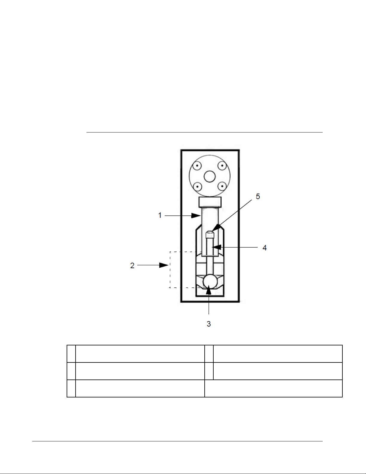
FIGURE 16.
Syringe Assembly (Inside Right Door)
1 Glass Syringe Barrel 4 Syringe Plunger - Pull out as indicated in Step 6 and
replace as referenced in Step 9.
2 Syringe Arm (between dotted lines) - Press down as
indicated in Step 4 and up as referenced in Step 10.
3 Set Screw - Loosen as indicated in Step 4 and
tighten as referenced in Step 11
For research use only. Not for use in diagnostic procedures.
5 Plunger Seal (contains O ring) - Replace as
indicated in Step 7.
Maintenance and Cleaning
33
Page 44
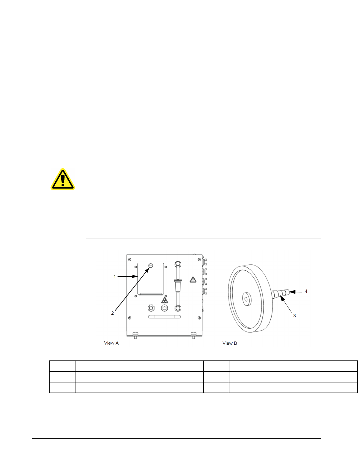
Replacing the HEPA Air Filter
The HEPA air filter is the round filter behind the panel on the left side of the front of the
fluidics bay. Tubing from the interior of the fluidics bay is attached to the stem in the center
back of the filter.
To replace the HEPA air filter:
1.
Turn off the Luminex® FLEXMAP 3D® instrument and unplug the power cord.
2. Open the left door and locate the HEPA air filter panel on the front of the fluidics bay as
shown in the HEPA Air Filter image below.
3. Remove the screw at the top of the panel and open the panel door as shown in the
HEPA Air Filter image below.
4. Grasp the tubing and pull the filter 3 to 4 inches from the unit.
5. Remove the filter with one hand and hold the tubing with the other hand.
CAUTION: Do not allow the tubing to fall inside the instrument.
6. Connect a new filter to the tubing and position the filter inside the panel.
7. Reattach the panel door to the unit and close the access door.
8. Plug in the power cord and turn on the FLEXMAP 3D® instrument.
FIGURE 17.
View A Front of fluidics bay View B HEPA Filter
1 Filter panel 3 Filter Stem
2 Screw - Remove as indicated in Step 3. 4 Attachment point for tubing
HEPA Air Filter
Luminex® FLEXMAP 3D® Hardware User Manual
34
For research use only. Not for use
in diagnostic procedures.
Page 45

Cleaning the Ventilation Filters
Each filter has at least one imprinted arrow on its metal frame. This arrow indicates the
direction of the air flow. Filters should be installed so that the arrows are at the correct
locations and point in the correct direction.
To clean the Luminex® FLEXMAP 3D® ventilation filters:
1.
Turn off the FLEXMAP 3D® instrument and unplug the power cord.
2. Remove the XY cover by gently grasping its ventilation holes and pulling it straight out.
3. Slide clamps off the silver filter inside the cover and remove the filter.
NOTE: For filter location, reference the "Ventilation Filter on XY Platform"
image below.
4. Open the front doors. Slide clamps off the left and right silver door filters and remove the
filters.
NOTE: For clamp location, reference the "Ventilation Filters inside Doors"
image below.
5. Clean the filters with a vacuum or with deionized water.
6.
Stand the filters upright to air dry.
CAUTION: Filters must be completely dry prior to reinstallation.
7. Reinstall filters. The arrows on the door filters should point to the inside of the door. The
arrow on the XY filter should point up.
For research use only. Not for use in diagnostic procedures.
Maintenance and Cleaning
35
Page 46

8. Reinstall the XY cover and close the access doors.
Plug in the power cord and turn on the FLEXMAP 3D® instrument.
9.
FIGURE 18.
View A Front of the FLEXMAP 3D® instrument with XY
cover in place
1 XY Cover (inside dotted lines) 3 Filter
2 Location of ventilation holes on top of XY cover
(visible only when doors are open)
Ventilation Filter on XY Platform
View B Front of the FLEXMAP 3D® instrument with XY
cover removed
4 Filter Clamp
FIGURE 19.
5 Incised Arrow
Ventilation Filters inside Doors
Luminex® FLEXMAP 3D® Hardware User Manual
36
For research use only. Not for use
in diagnostic procedures.
Page 47

View A Right front door, viewed from inside 2 Filter Clamp
View B Left front door, viewed from inside 3 Incised Arrow
1 Filter
Annual Maintenance
Annual maintenance requires replacing the sheath filter.
To replace the Luminex®
1. Turn off the FLEXMAP 3D® instrument and unplug the power cord.
2. Open the left door on the FLEXMAP 3D® instrument and locate the sheath filter on the
front of the fluidics bay.
3. Disconnect the filter by pushing down on the metal clamps at each quick-disconnect
point.
NOTE: For information on the location of the disconnection clamps,
reference the "Front of Fluidics Bay (Inside Left Door)" image below.
4. Connect the new sheath filter, matching up the color-coded fittings. The arrow on the
sheath filter should be pointing up.
5.
Close the left door.
FLEXMAP 3D® instrument sheath filter:
For research use only. Not for use in diagnostic procedures.
Maintenance and Cleaning
37
Page 48

6. Plug in the power cord and turn on the FLEXMAP 3D® instrument.
Use the software to run the prime command twice.
7.
FIGURE 20.
Front of Fluidics Bay (Inside Left Door)
1 Top quick-disconnect point
2 Sheath Filter
3 Bottom quick-disconnect point
Storing the Luminex® FLEXMAP 3D®
If you need to put the Luminex® FLEXMAP 3D® instrument in long-term storage or prepare it
for use after removing it from long-term storage, use the following procedures.
Storing the Luminex® FLEXMAP 3D® Instrument
This procedure explains the steps you should take before placing the Luminex® FLEXMAP
3D® instrument into long-term storage.
To prepare the FLEXMAP 3D® instrument for storage:
1. Use the software to perform a Preparation for storage routine.
Luminex® FLEXMAP 3D® Hardware User Manual
38
For research use only. Not for use
in diagnostic procedures.
Instrument
Page 49

2. Remove the sample probe from the instrument and flush it with deionized water from the
narrow end out through the larger end.
Replace the sample probe in the sample arm and wrap the end of the probe with
3.
Parafilm®.
Preparing the Luminex® FLEXMAP 3D® Instrument for Use After Storage
Follow this procedure before you begin using the Luminex® FLEXMAP 3D® instrument after
its removal from long-term storage.
To prepare the FLEXMAP 3D® instrument for use after storage:
1. Make sure that the sheath container has a sufficient amount of sheath fluid and that the
waste fluid container is empty.
2. Remove the Parafilm from the end of the sample probe.
3. Turn on the FLEXMAP 3D® instrument and watch for the following indications of correct
response:
• The compressor starts. It has a low rumbling sound.
• Air blows out of the rear fans. Place your hand behind the FLEXMAP 3D® instrument,
on the upper part of the back, to feel it.
NOTE: For the fan location, see the "Back of the FLEXMAP 3D®
• The syringes inside the right door of the FLEXMAP 3D® instrument initialize.
4. Turn on the PC and start up the software. Use the software to run a revival after storage
routine.
Replacing Fuses
Periodically, you may need to replace a fuse on the Luminex® FLEXMAP 3D® instrument. The
instrument requires fuses with the following specifications:
F6A, 250 V
The fuse cartridge will accept either 5 mm x 20 mm or 0.25” x 1.25” fuses. Fuses are
available from Luminex Corporation. Replacing a fuse requires access to the back of the
FLEXMAP 3D® instrument. Be aware before attempting any necessary lifting or movement of
the instrument that it weighs approximately 91 kg (200 lbs). Lifting it requires five people.
DANGER: To avoid serious injury or death by electric shock, you must turn
To replace a fuse:
image below.
off the FLEXMAP 3D®
before replacing a fuse.
Instrument"
instrument and unplug it from the wall
1.
Unplug the power cable from the instrument.
2. Use a small, flat-blade screwdriver to open the module door on the lower left corner of
the back of the instrument. The door opens downward. Inside are two cartridges, a red
one on top and a black one on the bottom.
3. Use the screwdriver to remove the red cartridge.
For research use only. Not for use in diagnostic procedures.
Maintenance and Cleaning
39
Page 50

4. Check both of the fuses in the cartridge for damage. A fuse can display physical
evidence of damage, for example, broken wire or blackened glass; if it displays no
physical evidence, test it for continuity with a voltmeter.
Replace damaged fuses with the type specified on the sticker to the right of the power
5.
input module.
6. Replace the red cartridge.
7. Shut the module door.
8. Plug in the power cord and turn on the FLEXMAP 3D® instrument.
NOTE: If your FLEXMAP 3D® instrument is not on a swivel base and it
requires moving in order for you to access the back of the
instrument, use the software to re-calibrate and re-verify the
instrument after it is restored to its original location.
FIGURE 21.
Back of the FLEXMAP 3D® Instrument
1 Power Module
2 Location to insert screwdriver to open module door, as referenced in Step 2
3 Fuse Information
Maintenance Logs
Use the Maintenance Logs (located in Appendix E) to record maintenance information. Fill in
the dates in the first line of the table. The first table includes a sufficient number of columns
for one week (7 days). The second table includes a sufficient number of columns for monthly
Luminex® FLEXMAP 3D® Hardware User Manual
40
For research use only. Not for use
in diagnostic procedures.
Page 51

maintenance (one task monthly), semi-annual maintenance (two tasks twice yearly), and
annual maintenance (two tasks yearly). For each item listed at the left, enter your initials
under each date on which you perform the task.
Use the Maintenance Logs (located in Appendix E) to record maintenance information. In the
Short Term Maintenance Schedule, the first table includes a sufficient number of columns
for daily maintenance recordings for one week (7 days). The second table provides space for
a weekly maintenance recording (one column).
In the Long Term Maintenance Schedule, the first table includes a sufficient amount of
space to record monthly maintenance tasks. The second table, provides space to record
semi-annual maintenance (two tasks twice yearly), and the third table includes a sufficient
amount of space to record annual maintenance tasks. For each item listed, enter your initials
under each date on which you perform the task.
For research use only. Not for use in diagnostic procedures.
Maintenance and Cleaning
41
Page 52

Luminex® FLEXMAP 3D® Hardware User Manual
42
For research use only. Not for use
in diagnostic procedures.
Page 53

Chapter 4: Troubleshooting
Troubleshooting procedures help users identify and remedy problems with the instrument.
Overview
To troubleshoot a problem, locate the symptom in one of the tables in this chapter, determine
the cause from the listed possibilities, and remedy it with the provided solution.
This chapter supplies information about the following topics:
Power Supply Problems
•
• Communication Problems
• Clogs
• Pressurization Problems
• Fluid Leaks
• Sample Probe Problems
• Calibration Problems
• Verification Problems
• Acquisition Problems
• Bead Detail Irregularities
Contact Luminex Technical Support in the U.S. and Canada by calling 1-877-785-BEAD
(-2323). Outside of the U.S. and Canada, call +1 512-381-4397. Contact Luminex Technical
Support in Europe by calling +31 162 408 333. Email inquiries to support@luminexcorp.com.
Additional information is available on the Luminex website. Search the desired topic or
navigate through menus. Also, review the website’s FAQ section. Enter http://
www.luminexcorp.com in your browser’s address field. Click Support> Support Login to log
into the Support FAQ site.
This chapter does not troubleshoot problems with the PC. For help with PC problems, please
contact the technical support department for the manufacturer of your PC.
43
Page 54

Power Supply Problems
Power supply problems often involve a blown fuse, faulty electronic component, or
disconnected cable.
CAUTION: Whenever you deal with a potential electrical problem, be careful
to avoid electrical shocks.
TABLE 1.
Symptom Possible cause Solution
The Luminex® FLEXMAP 3D
instrument will not turn on.
Fuses continue to open (blow). A component has a short circuit. Contact Technical Support.
Power Supply Problems
®
The power cord is disconnected. Plug in the power cord.
No voltage is coming from the electrical
outlet.
The power supply is faulty. Contact Technical Support.
A fuse has burned out See the section titled Replacing Fuses.
Communication Problems
Communication problems described in this section involve the links between the data system
(PC and software) and the
address communication issues with other peripheral devices.
“Communication” refers to the transfer of data between the PC and the FLEXMAP 3D
instrument, including the current status of the instrument, instrument control, sample
acquisition, session uploading, and start, stop, and pause features.
Luminex® FLEXMAP 3D® instrument. This section does not
Verify that the electrical outlet is
operational.
Use extreme care when replacing a fuse.
®
TABLE 2.
Symptom Possible cause Solution
The PC cannot establish
communication with the
FLEXMAP 3D® instrument.
Communication Problems
The communication cable is unplugged or
plugged into the wrong port.
The FLEXMAP 3D® instrument is not
turned on.
Luminex® FLEXMAP 3D® Hardware User Manual
44
Plug in or move the communications cable.
Turn off the PC. Turn on the FLEXMAP
3D® instrument and then turn on the PC.
For research use only. Not for use
in diagnostic procedures.
Page 55

Clogs
Often, a clog somewhere in the Luminex® FLEXMAP 3D® instrument is the cause of a fluid
leak, a pressurization or sample probe problem, or a problem with calibration, verification, or
data acquisition.
To determine whether there is a clog, check the bead count during calibration. During
calibration you should see 300 bead events per second or more. If there are fewer than that,
there is probably a clog in the instrument.
In the event you encounter a problem that is clog-related, use the following procedure.
To troubleshoot a possible clog:
Clean and adjust the sample probe. See the section titled “Cleaning the Sample Probe”.
1.
2. Perform the procedure for removing clogs. See the section titled “Removing Clogs”.
3. Replace all fluids.
4. Use the software to run the weekly maintenance routine.
5. Run calibration and verification.
If this procedure is unsuccessful, call Luminex Technical Support.
Pressurization Problems
Normal air and sheath pressure readings vary between 8 and 13 psi while the compressor
runs. If the instrument pressure is out of range, sample acquisition either can fail or can
return inadequate results.
TABLE 3.
Symptom Possible cause Solution
Pressurization fails or pressure is
too low.
Pressurization Problems
The sheath and waste lines are not fully
connected.
The sheath or waste fittings are cracked. Inspect the fittings to be sure they form a
There is a leak in the instrument. Check for leaks. A leak is obvious if there
The compressor does not engage. Use the software to run a prime command.
Check the lines between the sheath and
waste bottles and the
3D® instrument.
tight seal. If not, call Technical Support.
is fluid on the surface where the FLEXMAP
3D instrument sits. See the section titled
“Fluid Leaks”.
If you do not hear the compressor turn on,
contact Technical Support.
Luminex® FLEXMAP
For research use only. Not for use in diagnostic procedures.
Troubleshooting
45
Page 56

Fluid Leaks
Fluid leaks can result in poor pressurization and failed sample acquisition.
TABLE 4.
Symptom Possible cause Solution
Fluid is pooled around the
Luminex® FLEXMAP 3D
instrument.
Fluid drips from the sample probe. The sample probe is clogged. See the section titled “Clogs”.
Fluid leaks from the front of the
instrument.
Fluid Leaks
®
Fittings or fluid lines are damaged. Turn off and disconnect the instrument to
The sample valve is faulty. Contact Technical Support.
The syringe seal leaks. Replace the syringe seal. See the section
The syringe valve leaks. Hand-tighten the syringe connection (silver
Sample Probe Problems
Problems with the sample probe can lead to fluid leaks and pressurization problems, and
they can inhibit sample acquisition.
avoid electrical shock and contact
Technical Support.
titled “Replacing the Syringe Teflon Seals”.
knob) on the syringe valve. Use the
software to run a prime command. If leaks
continue, contact Technical Support.
TABLE 5.
Symptom Possible cause Solution
The sample probe leaks. The sample probe is clogged. See the section titled “Clogs”.
The sample arm is stuck in the up
or down position.
The sample arm does not go
down smoothly.
Sample Probe Problems
The sample probe motor connections are
loose.
The sample probe motor is faulty. Contact Technical Support.
Probe calibration not done. Perform Automatic Probe Height
The microtiter plate is incorrectly seated. Adjust the microtiter plate.
Luminex® FLEXMAP 3D® Hardware User Manual
46
Contact Technical Support.
Adjustment using the software.
For research use only. Not for use
in diagnostic procedures.
Page 57

TABLE 5.
Symptom Possible cause Solution
Sample Probe Problems Continued
Calibration Problems
The microtiter plate is warped. Inspect the microtiter plate. Replace it if it
is warped.
The sample probe is bent. Remove the sample probe from the
instrument. Roll it on a flat surface. If a
sample probe has been bent and rolled
straight more than once, discard it and
replace it with a new sample probe.
Perform an automatic sample probe height
adjustment using the software.
TABLE 6.
Symptom Possible cause Solution
Calibration is slow or fails. The calibration microspheres are not fully
Calibration Problems
suspended.
The wrong lot number or target values are
entered in the appropriate software user
interface.
The instrument calibrators are in the wrong
well.
There are not enough calibrator
microspheres in the well.
The calibrator lot is expired. Use an unexpired bottle of calibrator
The sample probe height is incorrect. Perform an automatic sample probe height
The sample probe is clogged. See the section titled "Clogs".
There is a partial clog in the instrument. See the section titled "Clogs".
Vortex the calibration vials to resuspend
the microspheres.
Check the lot number and target values to
make sure they are correct.
Verify that calibration microspheres are in
the correct well.
Add at least five drops of calibrator
microspheres to the well. For accurate
drop volume, hold the vial upside down at
a 90 degree angle to the microtiter plate
while dispensing them.
microspheres.
adjustment.
There is air in the instrument. The waste
line was moved during instrument
operation, resulting in an unstable flow
rate.
The waste line was moved during
instrument operation, resulting in an
unstable flow rate.
For research use only. Not for use in diagnostic procedures.
Perform an automatic sample probe height
adjustment. Use the software to run a
prime command three times, an alcohol
flush command twice, then a wash
command three time with deionized water.
Stabilize the waste line during instrument
operation. See the section titled
“Maintaining Fluids”.
Troubleshooting
47
Page 58

TABLE 6.
Symptom Possible cause Solution
Calibration Problems Continued
There is a problem internal to the
instrument.
No events are collected during
calibration.
There is a problem with fluid levels. Check the sheath and waste fluid levels.
The sample probe is clogged. See the section titled "Clogs".
The Cheminert fitting is loose. Tighten the Cheminert fitting.
Verification Problems
TABLE 7.
Symptom Possible cause Solution
The instrument fails verification. The verification microspheres are not fully
Verification Problems
suspended.
Review the log of calibration reports.
Check for dramatic changes in
temperature, sheath pressure, or voltage. If
any of these are present, contact Technical
Support.
Verify that tubing for both bottles is tightly
connected to the instrument. Check that
the waste fluid container cap is vented.
Vortex the verification vials to resuspend
the microspheres.
The wrong lot number or target values are
entered in the appropriate page of the
software UI.
The instrument verification microspheres
are in the wrong well.
There are not enough verification
microspheres in the well.
The verification lot is expired. Use an unexpired bottle of verification
The verification microspheres have been
diluted.
The sample probe height is incorrect. Perform an automatic sample probe height
The sample probe is clogged. See the section titled “Clogs”.
There is air in the instrument. Verify the sample probe height. Use the
Check the lot number and target values to
make sure they are correct.
Verify that verification microspheres are in
the correct well.
Add at least five drops of verification
microspheres to the well. For accurate
drop volume, hold the vial upside down at
a 90 degree angle to the microtiter plate
while dispensing them.
microspheres.
Do not dilute the verification microspheres.
adjustment.
software to run a prime command three
times, an alcohol flush command twice,
then a wash command three times with
deionized water.
Luminex® FLEXMAP 3D® Hardware User Manual
48
For research use only. Not for use
in diagnostic procedures.
Page 59

TABLE 7.
Symptom Possible cause Solution
Verification Problems Continued
The waste line was moved during
instrument operation, resulting in an
unstable flow rate.
There is a problem internal to the
instrument.
Acquisition Problems
TABLE 8.
Symptom Possible cause Solution
Acquisition fails or is slow. The air pressure is out of range. See the section titled “Pressurization
Verification Problems
The sample probe height is incorrect. Perform an automatic sample probe height
The sample probe is clogged. See the section titled “Clogs”.
Stabilize the waste line during instrument
operation. See the section titled
“Maintaining Fluids”.
Review the log of calibration reports.
Check for dramatic changes in
temperature, sheath pressure, or voltage. If
any of these are present, contact Technical
Support.
Problems”.
adjustment.
The sheath or waste lines are not fully
connected.
The calibration microspheres have expired. Replace old microspheres with an
The wrong wells are selected for the
calibration microspheres.
The wrong lot number or target values are
entered in the appropriate page of the
software UI.
Air is present in the instrument. Verify the sample probe height. Use the
The acquisition volume is set too high. Set the acquisition volume to at least 25μL
The Luminex® xMAP® microspheres are
not fully suspended.
Disconnect and reconnect the lines; you
should hear them click.
unexpired lot.
Ensure that the correct wells are selected
in the software.
Check the lot number and target values to
make sure they are correct.
software to run a prime command three
times, an alcohol flush command twice,
then a wash command three times with
deionized water.
less than the actual volume in your wells.
This enables the probe to acquire sample
more efficiently with less chance of
incorporating air in the sample.
Gently vortex the microtiter plate or
resuspend beads with a multichannel
pipettor to ensure that the microspheres
are present in the solution.
For research use only. Not for use in diagnostic procedures.
Troubleshooting
49
Page 60

TABLE 8.
Symptom Possible cause Solution
Verification Problems Continued
The microspheres are photobleached. Replace the microspheres with
unphotobleached microspheres.
There are an insufficient number of beads
in the sample.
The sample is too concentrated. Dilute concentrated biological fluids, such
Bead Detail Irregularities
Use these tools to assist in diagnosing system and kit-related problems:
instrument calibrators
•
• instrument verifiers
• assay standards
• assay controls
• error messages
Review calibration/control trend reports routinely to detect trends.
Use instrument Luminex® xMAP® verification microspheres to check the success of the
instrument calibration and to troubleshoot. If there is a problem with kit results, xMAP verifiers
can help determine if the problem is related to the instrument. If calibration and verification
are successful, contact the kit manufacturer.
The Bead Detail Irregularities table displays irregular groupings of beads. Compare the
displays to the following bead detail of a normal bead grouping - a tight bead population
within a white region.
Ensure that there are 2000 to 5000 beads
per bead set per well.
as serum or plasma, at least 1:5.
FIGURE 22.
Luminex® FLEXMAP 3D® Hardware User Manual
50
Normal Bead Detail
For research use only. Not for use
in diagnostic procedures.
Page 61

TABLE 9.
Symptom Description Possible Problem Solution
xMAP and calibrator microspheres form a group in the wrong location.
Bead Detail Irregularities
Calibrator microspheres group
together at the top of the
region.
xMAP microspheres group
together at the lower right of
the region.
xMAP microspheres form an unusual shape.
xMAP microspheres form a
long diagonal line.
xMAP microspheres form a
group with extending tails.
The calibrator microspheres
are photobleached.
The xMAP microspheres are
photobleached.
The xMAP microspheres have
agglutinated.
The solvent is incompatible. The Luminex Technical Support website
Replace the calibrator microspheres with
unphotobleached calibrator microspheres.
To avoid photobleaching, protect
microspheres from light.
Replace the xMAP microspheres with
unphotobleached xMAP microspheres. To
avoid photobleaching, protect microspheres
from light.
Contact Technical Support.
(http://www.luminexcorp.com/Support) lists
incompatible solvents. If the solvent you are
using is listed, switch solvents.
xMAP microspheres fail to form a group.
xMAP microspheres do not
form a cohestive group.
For research use only. Not for use in diagnostic procedures.
The sheath fluid is
incompatible.
Use only Luminex xMAP sheath fluid in the
Luminex® FLEXMAP 3D®
fluids can damage the instrument and void
your warranty.
instrument. Other
Troubleshooting
51
Page 62
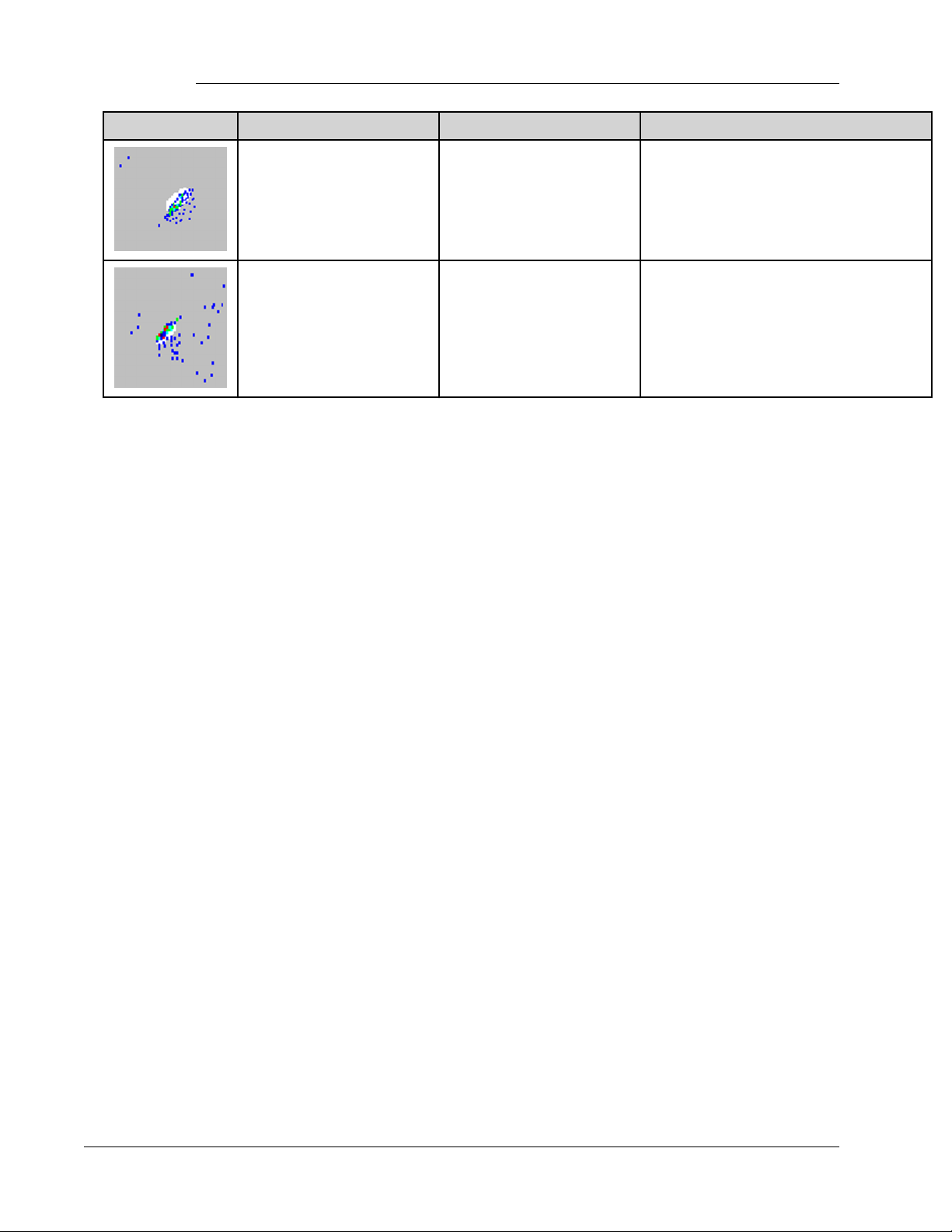
TABLE 9.
Symptom Description Possible Problem Solution
Bead Detail Irregularities Continued
xMAP microspheres do not
form a cohesive group and are
somewhat scattered.
xMAP microspheres are
widely scattered.
There is air in the instrument. Verify the sample probe height. Use the
software to run a prime command three
times, an alcohol flush command twice, then
a wash command three times with deionized
water.
The sheath fluid is empty. Make sure there is sheath fluid in the sheath
container. Use the software to run a prime
command until all air is pushed out of the
instrument.
Luminex® FLEXMAP 3D® Hardware User Manual
52
For research use only. Not for use
in diagnostic procedures.
Page 63

Appendix A: Shipping
Shipping
If a serious problem arises with the
return it to Luminex Corporation for repairs. If Luminex Technical Support directs you to
return the FLEXMAP 3D® system, the Technical Support representative will provide you with
all necessary information as well as give you a Return Material Authorization (RMA) number.
NOTE: Before the instrument is returned, two procedures must be
performed: The instrument must be decontaminated and its reservoir
must be drained. For the decontamination procedure, see the section
titled “Decontamination Procedure”. For instructions on draining the
reservoir, see the section titled “Draining the Reservoir”.
Draining the Reservoir
To drain the reservoir:
1. Make sure the waste fluid container can hold at least one additional liter of fluid.
2. Disconnect the sheath fluid tubing from the sheath fluid container.
3. Disconnect the sheath filter tubing (white connector) from its bottom quick disconnect
point (white connection) on the fluidics bay.
4. Disconnect the waste fluid tubing (orange connector) from the orange connection on the
fluidics bay.
5. Disconnect the sheath fluid tubing (blue connector) from the blue connection on the
fluidics bay.
Luminex® FLEXMAP 3D® system, it may be necessary to
53
Page 64

6. Connect the waste fluid tubing (orange connector) to the bottom quick disconnect point
(white connection) of the sheath filter tubing.
Use the software to run a warmup command. This starts the compressor, which drains
7.
the sheath fluid from the reservoir into the waste fluid container.
NOTE: To refill the reservoir, reconnect each connector to its color-matched
connection and use the software to run a prime command.
FIGURE 23.
1 White connection for sheath fluid tubing - Disconnect as referenced in Step 3
2 Orange connection for waste fluid tubing - Disconnect as referenced in Step 4
Front of Fluidics Bay
3 Blue connection for sheath filter tubing - Disconnect as referenced in Step 5
Shipment Checklist
Complete the following checklist, sign and date it, and return it with the
3D® system.
1. Remove all specimens from the instrument.
2. Decontaminate the instrument. See the section titled “Decontamination Procedure”.
3. Drain the reservoir. See the section titled “Draining the Reservoir”.
Was there an internal leak in the system?
Luminex® FLEXMAP 3D® Hardware User Manual
54
Luminex® FLEXMAP
For research use only. Not for use
in diagnostic procedures.
Page 65

Yes
No
Printed Name _____________________________________________________
Signature ________________________________________________________
Company/Institution ________________________________________________
Date________________ Instrument Serial No.___________________________
For research use only. Not for use in diagnostic procedures.
Shipping
55
Page 66

Luminex® FLEXMAP 3D® Hardware User Manual
56
For research use only. Not for use
in diagnostic procedures.
Page 67

Appendix B: Installation
Installation of the Luminex® FLEXMAP 3D
The following installation instructions for
prep, assessing facilities requirement and in the event cabling or tubing must be reconnected.
NOTE: If you do not intend to keep the packing material for future use,
return the packaging of the product, spare parts, and options to the
manufacturer with the Field Service Engineer. Within the European
Union and other jurisdictions, in accordance with the European
Parliament and Council Directive 94/62/EC
packaging waste, the manufacturer is responsible for the disposal of
packing material.
To install FLEXMAP 3D®:
1. Place the PC and monitor on the right side of the instrument.
Luminex® FLEXMAP 3D® are to be used for site
regarding packaging and
®
57
Page 68

2. Connect the FLEXMAP 3D® instrument and all necessary peripheral devices to the PC.
FIGURE 24.
1. Monitor Plug 5. Monitor Plug (Touchscreen monitors only)
2. FLEXMAP 3D Communications Plug (USB
type A )
3. Mouse Plug 7. Stereo Speaker Audio Connection
4. Barcode Scanner Plug 8. Power Inlet
Back of PC
6. Stereo Speaker Power (USB connection)
FIGURE 25.
Back of FlexMAP 3D Instrument
Luminex® FLEXMAP 3D® Hardware User Manual
58
For research use only. Not for use
in diagnostic procedures.
Page 69

1. Power Inlet 2. PC Communications plug (USB
type B)
3. Connect the USB communications cable between the FLEXMAP 3D® instrument (P1)
and the PC, and connect the power cables for the PC, monitor, and
FLEXMAP 3D
®
instrument to outlets but do not turn on any of the devices.
4. Place the sheath container below the instrument with the container opening facing up.
5. Remove the existing container cap and install the cap from the blue tubing accessory in
its place.
6. Connect the blue sheath line to both the disconnect on the sheath container and the blue
connector on the outside of the instrument.
FIGURE 26.
Sheath and Waste Container Connections
7. Place the empty waste container below the instrument with the container opening facing
up.
Remove the existing container cap and install the cap from the orange tubing accessory
8.
in its place.
9. Connect the orange waste line to both the disconnect on the waste container and the
orange connector on the outside of the instrument.
10. Open the two front access doors.
11. Turn on the FLEXMAP 3D® instrument using the power switch on the right side of the
instrument, toward the back.
12. Observe the indicators associated with powering up a FLEXMAP 3D® instrument.
13. Visually inspects for leaks.
14. Turn on the PC and monitor.
15. Close the access doors.
16. If the system includes a touch screen monitor, test it by touching the screen. The mouse
cursor should move to the location you touched. If monitor does not respond, use the
supplied CD to install the drivers. If the mouse cursor responds correctly, calibrate the
monitor using the software preloaded onto the PC.
17. Access the Luminex® xPONENT® software on the PC and confirm that the instrument is
communicating with the software.
For research use only. Not for use in diagnostic procedures.
Installation
59
Page 70

18. Calibrate the probe height using the instructions in the software user manual.
NOTE: For information on calibrating the probe height when using soft-
bottom 384-well plates, refer to the FLEXMAP 3D 384-Well Plate
Probe Height Adjustment Tool section.
19. Calibrate the instrument using the instructions in the software user manual.
Luminex® FLEXMAP 3D® Hardware User Manual
60
For research use only. Not for use
in diagnostic procedures.
Page 71

For research use only. Not for use in diagnostic procedures.
Installation
61
Page 72

Luminex® FLEXMAP 3D® Hardware User Manual
62
For research use only. Not for use
in diagnostic procedures.
Page 73

For research use only. Not for use in diagnostic procedures.
Installation
63
Page 74

Luminex® FLEXMAP 3D® Hardware User Manual
64
For research use only. Not for use
in diagnostic procedures.
Page 75

Appendix C: Part Numbers
Hardware
Product Description Customer Number
Luminex® FLEXMAP 3D®
Heater Block for 96-well microtiter plates CN-0224-01
Heater Block for 384-well microtiter plates CN-0223-01
Bar Code Scanner CN-PC03-01
Air Filter: Access Door CN-0222-01
Air Filter: XY Platform CN-0229-01
Air Filter: HEPA CN-0228-01
Syringe Cylinder with seal CN-0013-01
Syringe Seal (Quantity 4) CN-0014-01
Sheath Filter with quick disconnect CN-0010-01
Sample Probe Height Adjustment Kit CN-0015-01
Cable, USB (A to B) CN-0227-01
Cable, Power CN-PXXX-01
Fuse (6 amp) CN-0226-01
Sample Probe Needle CN-0221-01
Off-plate Reservoir CN-0225-01
Automated Maintenance Plate CN-0206-01
with xPONENT FLEXMAP-3D-RUO
PM (Preventive Maintenance) Kit CN-0215-01
65
Page 76

Software
Product Description Customer Number
Luminex xPONENT Software for FLEXMAP 3D
Reagents
Product Description Customer Number
xMAP Sheath Fluid, LX100 40-50000
FLEXMAP 3D® Calibration Kit F3D-CAL-K25
Microspheres, F3DCAL1 - Classification Calibrator F3DCAL1-05
Microspheres, F3DeCAL1 - Classification Calibrator F3DeCAL1-05
Microspheres, F3DCAL2 - Reporter Calibrator F3DCAL2-05
Microspheres, F3DCAL3 - EDR Calibrator F3DCAL31-05
FLEXCAP 3D Performance Verification Kit F3D-PVER-K25
®
CN-SW16-01
Microspheres, F3DVER1 - Classification Verifier F3DVER1-05
Microspheres, F3DeVER1 - Classification Verifier F3DeVER2-05
Microspheres, F3DVER2 - Reporter Verifier F3DVER3-05
Microspheres, Fluidics1 - xMAP Fluidics 1 FLUID1-05
Microspheres, Fluidics2 - xMAP Fluidics 2 FLUID2-05
Luminex® FLEXMAP 3D® Hardware User Manual
66
For research use only. Not for use
in diagnostic procedures.
Page 77

Appendix D: FLEXMAP 3D®
Adjustment Tool
NOTE: The Luminex® FLEXMAP 3D® Probe Height Adjustment Tool is to be
used for 384 well mylar bottom and 384 well filter bottom plates only.
To calibrate the probe correctly, perform the following steps:
Using data sheet for the plate you intend to calibrate the probe to, subtract the "well
1.
depth" from the "plate height" as shown in the example below:
Probe Height
Plate Height: 14.2mm - Well Depth: 11.43mm = 2.77mm (2.8mm)
Example 1: 2.8mm or well C7 on the probe height adjustment tool for this example.
67
Page 78

2. Click Eject from the System Status bar to eject the XY platform.
Place the probe height adjustment tool on the XY platform.
3.
4. From the Home page click Probe and Heater.
5. On the Probe and Heater page, select the plate type (384 well) and enter a plate name.
6. Select the appropriate well to calibrate probe height (C7 for the example shown above).
7. Click Auto Adjust Height.
8. Click Save to save the plate settings.
Example 2: "C" Plate Height 14.4mm - "F" Well Depth 11.5mm = 2.9mm
2.9mm or well D7 on the probe height adjustment tool for this example.
Luminex® FLEXMAP 3D® Hardware User Manual
68
For research use only. Not for use
in diagnostic procedures.
Page 79

For research use only. Not for use in
diagnostic procedures.
FLEXMAP 3D® Probe Height Adjustment Tool
69
Page 80

Luminex® FLEXMAP 3D® Hardware User Manual
70
For research use only. Not for use
in diagnostic procedures.
Page 81

Appendix E: Maintenance Schedule
Short Term Maintenance Schedule
71
Page 82

Luminex® FLEXMAP 3D® Hardware User Manual
72
For research use only. Not for use in diagnostic procedures.
Page 83

Appendix E: Maintenance Schedule
Long Term Maintenance Schedule
73
Page 84

Luminex® FLEXMAP 3D® Hardware User Manual
74
For research use only. Not for use in diagnostic procedures.
Page 85

Appendix E: Maintenance Schedule
75
Page 86

Luminex® FLEXMAP 3D® Hardware User Manual
76
For research use only. Not for use
in diagnostic procedures.
 Loading...